EP3676592B1 - Sample collection system and parts thereof - Google Patents
Sample collection system and parts thereof Download PDFInfo
- Publication number
- EP3676592B1 EP3676592B1 EP18850114.2A EP18850114A EP3676592B1 EP 3676592 B1 EP3676592 B1 EP 3676592B1 EP 18850114 A EP18850114 A EP 18850114A EP 3676592 B1 EP3676592 B1 EP 3676592B1
- Authority
- EP
- European Patent Office
- Prior art keywords
- material stream
- cone
- sample
- collection system
- sample collection
- Prior art date
- Legal status (The legal status is an assumption and is not a legal conclusion. Google has not performed a legal analysis and makes no representation as to the accuracy of the status listed.)
- Active
Links
- 239000000463 material Substances 0.000 claims description 119
- 230000003068 static effect Effects 0.000 claims description 33
- 239000002699 waste material Substances 0.000 claims description 22
- 230000005484 gravity Effects 0.000 claims description 7
- 239000002245 particle Substances 0.000 claims description 4
- 238000005070 sampling Methods 0.000 description 11
- 239000007788 liquid Substances 0.000 description 7
- 239000011236 particulate material Substances 0.000 description 6
- 239000012530 fluid Substances 0.000 description 5
- 238000005553 drilling Methods 0.000 description 4
- 238000000034 method Methods 0.000 description 2
- 238000012216 screening Methods 0.000 description 2
- 238000004140 cleaning Methods 0.000 description 1
- 238000005520 cutting process Methods 0.000 description 1
- 230000001419 dependent effect Effects 0.000 description 1
- 238000009826 distribution Methods 0.000 description 1
- 230000007717 exclusion Effects 0.000 description 1
- 239000011344 liquid material Substances 0.000 description 1
- 230000003278 mimic effect Effects 0.000 description 1
- 238000012986 modification Methods 0.000 description 1
- 230000004048 modification Effects 0.000 description 1
- 230000003534 oscillatory effect Effects 0.000 description 1
- 230000000704 physical effect Effects 0.000 description 1
- 238000000926 separation method Methods 0.000 description 1
- 230000001360 synchronised effect Effects 0.000 description 1
- 238000009827 uniform distribution Methods 0.000 description 1
- 238000011144 upstream manufacturing Methods 0.000 description 1
Images
Classifications
-
- G—PHYSICS
- G01—MEASURING; TESTING
- G01N—INVESTIGATING OR ANALYSING MATERIALS BY DETERMINING THEIR CHEMICAL OR PHYSICAL PROPERTIES
- G01N1/00—Sampling; Preparing specimens for investigation
- G01N1/02—Devices for withdrawing samples
- G01N1/10—Devices for withdrawing samples in the liquid or fluent state
- G01N1/18—Devices for withdrawing samples in the liquid or fluent state with provision for splitting samples into portions
-
- G—PHYSICS
- G01—MEASURING; TESTING
- G01N—INVESTIGATING OR ANALYSING MATERIALS BY DETERMINING THEIR CHEMICAL OR PHYSICAL PROPERTIES
- G01N1/00—Sampling; Preparing specimens for investigation
- G01N1/02—Devices for withdrawing samples
- G01N1/10—Devices for withdrawing samples in the liquid or fluent state
- G01N1/20—Devices for withdrawing samples in the liquid or fluent state for flowing or falling materials
- G01N1/2035—Devices for withdrawing samples in the liquid or fluent state for flowing or falling materials by deviating part of a fluid stream, e.g. by drawing-off or tapping
-
- G—PHYSICS
- G01—MEASURING; TESTING
- G01N—INVESTIGATING OR ANALYSING MATERIALS BY DETERMINING THEIR CHEMICAL OR PHYSICAL PROPERTIES
- G01N1/00—Sampling; Preparing specimens for investigation
- G01N1/02—Devices for withdrawing samples
- G01N1/10—Devices for withdrawing samples in the liquid or fluent state
- G01N2001/1006—Dispersed solids
- G01N2001/1012—Suspensions
- G01N2001/1025—Liquid suspensions; Slurries; Mud; Sludge
-
- G—PHYSICS
- G01—MEASURING; TESTING
- G01N—INVESTIGATING OR ANALYSING MATERIALS BY DETERMINING THEIR CHEMICAL OR PHYSICAL PROPERTIES
- G01N1/00—Sampling; Preparing specimens for investigation
- G01N1/02—Devices for withdrawing samples
- G01N1/10—Devices for withdrawing samples in the liquid or fluent state
- G01N1/20—Devices for withdrawing samples in the liquid or fluent state for flowing or falling materials
- G01N1/2035—Devices for withdrawing samples in the liquid or fluent state for flowing or falling materials by deviating part of a fluid stream, e.g. by drawing-off or tapping
- G01N2001/205—Devices for withdrawing samples in the liquid or fluent state for flowing or falling materials by deviating part of a fluid stream, e.g. by drawing-off or tapping using a valve
Definitions
- the present invention generally relates to a sample collection system for collecting samples from a material stream.
- the invention has particular, but not exclusive, application in collecting samples of geological materials.
- Obtaining a representative sample of a material stream can be difficult for a variety of reasons. For example, variations in particle size and/or density, can impact sample collection. Furthermore, upstream material flow dynamics can impact on the sample actually collected by the sampler at the point of collection.
- sample collectors have been developed to date. Such collectors fall into two broad categories: mechanical and static.
- Mechanical samplers include a powered mechanism that periodically moves one or more sampling orifices through the material stream. That movement may adopt a linear motion such as that used in a cross-stream sampler, a rotary motion as used in a rotary-port splitter, rotary cone splitter or Vezin splitter, or an oscillatory motion.
- a static sampler (sometimes referred to as a stationary sampler) has a static orifice that continuously intersects the material stream. Examples of static samplers include a riffle splitter, a cone splitter, and a launder box or shark-fin splitter.
- Static splitters typically collect a proportion of the material stream constantly. However, they can be affected by preferential sampling or exclusion of material with certain physical properties due to material flow characteristics or poor mixing. For this reason, static splitters are not generally preferred over mechanical splitters which can collect a full cross-section of the material stream over a specific time interval. However, sampling of a material stream of particulate materials suspended in a flowing liquid via a mechanical splitter is not recommended as the sampling mechanism disturbs the flow and thus biases the sample.
- Static cone splitters are a type of static splitter which were commonly used for taking a sub-sample of dry particulate material or particulate material with a low concentration of liquid (i.e. ⁇ 10% liquid). However, in more recent times, rotary cone splitters and other variants are more commonly used when sampling such materials.
- static cone splitters are not recommended for sampling of liquid or particulate materials suspended in a flowing liquid (e.g. a material stream of the type produced through coiled tubing drilling). This is due to the potential for disturbed or preferential flow paths therewithin, siphoning, air entrainment, and their inability to function accurately over varying flow velocities. All of these factors impart biasing of the sample collected.
- the present invention seeks to provide an improved sample collection system for collecting a continuous sub-sample of a material stream, and an improved static cone splitter.
- Document US 5 241 867 A shows a method and apparatus for apportioning a primary volume of fluid into a plurality of secondary volumes having a predefined mutual relationship, by means of a chamber for receiving the primary volume of fluid having a bottom including fluid evacuation orifices disposed in a common horizontal plane and connected to evacuation ducts provided with cocks, enabling the beginning of fluid flow in the ducts to be synchronized, with the end of said flow being determined by the free surface of the fluid being fractioned by the evacuation orifices.
- Document WO 2011/035377 A1 shows an apparatus for collecting samples of drilled material.
- the apparatus comprises a drilled material / gas separation means such as a cyclone and a sampling assembly preferably comprising upper and lower chambers and a spreader for splitting samples.
- the cyclone may comprise a filter arrangement to prevent smaller diameter drilled materials entrained in the gas stream exiting the cyclone via gas vent.
- the spreader may comprise a rotating nozzle outlet from which drilled material exiting the cyclone is delivered onto a conical surface. Rotation of the nozzle outlet ensures even distribution of drilled material around the conical surface which in turn ensures that samples are delivered to the sample receptacles with maximum homogeneity.
- a sample collection system for collecting sub-samples from a material stream, said system including a valve arrangement and a static cone splitter, and wherein the valve arrangement is arranged to enable operation of the static cone splitter to collect a non-biased sample of the material stream fed to the static cone splitter under first and second operational conditions, the first operational condition requiring the material stream to be at substantially atmospheric pressure and flowing at a minimum functional flow rate, and the second operational condition requiring the material stream to be pressurised above atmospheric pressure and at a flow rate higher than the minimum functional flow rate, wherein the valve arrangement includes an air valve which, at the minimum functional flow rate of the material stream, remains open allowing air to enter the valve arrangement to allow the material stream to flow without restriction at substantially atmospheric pressure, wherein at flow rates higher than the minimum functional flow rate the air valve is arranged to allow the evacuation of air from the system until the system is full of material stream at which point the air valve closes.
- material stream is used to reference a stream of liquid in which particulate material is transported.
- minimum functional flow rate is the lowest flow rate expected during system operation for which a representative sub-sample is required and under which a representative sub-sample cannot be guaranteed.
- maximum functional flow rate is the maximum expected flow rate of the system for which a representative sub-sample is required and over which a representative sub-sample cannot be guaranteed.
- the valve arrangement is a passive component that operates automatically dependant on the flow rate of the material stream.
- the valve arrangement preferably includes an air valve which, at the minimum functional flow rate of the material stream, remains open allowing air to enter the valve arrangement to allow the material stream to flow without restriction at substantially atmospheric pressure.
- no vacuum is generated in the system and thus a reverse flow of air into the system via a sample outlet tube or a waste outlet tube of the static cone splitter is prevented. If such a vacuum was to occur, reverse flow of the material stream through the system would cause imbalance between the sample outlet tube and the waste outlet tube causing uneven flow of the material stream through the static cone splitter and hence the collection of a biased sample.
- the air valve is arranged to allow the evacuation of air from the system until the system is full of material stream at which point the air valve closes. Once closed, the system operates as a pressurized system at higher flow rates without the entrainment of air. Whilst operating as a pressurized system, the material stream is pushed through the static cone splitter and remains pressurized up to the point of passing a cone member of the cone splitter.
- the cone member includes openings that divide the material stream into sub-streams. After that point, the material stream is broken into sub-streams including at least one waste stream and at least one sample stream which each flow at atmospheric pressure.
- waste streams and sample streams flow through the respective waste and sample outlet tubes freely under the action of gravity. This allows the system to maintain a balance of pressure between outlets of the waste and sample outlet tubes and hence the openings of the cone member. This results in a balanced and unbiased split of the material stream into the various sub-streams.
- the material stream is arranged to flow into a chamber prior to entry into the static cone splitter.
- the valve arrangement is connected to the chamber distal from the cone splitter.
- the cone splitter is located substantially vertically below the chamber and is connected thereto by a substantially vertical chamber exit pipe.
- the vertical chamber exit pipe connects to an inlet tube of the static cone splitter.
- the inlet tube has a cross-sectional flow area that is defined by the minimum functional flow rate of the system and is sized such that the unrestricted flow by gravity of the material stream through the inlet tube is substantially equal to or less than the minimum functional flow rate of the system without overly restricting the system flow. In this way, the inlet tube will remain charged with material stream during use of the sample collection system for flow rates equal to or greater than the minimum functional flow rate.
- the sample collection system of an embodiment of the invention is preferably configured to receive the material stream at a flow rate of greater than about 60 litres per minute and less than about 150 litres per minute.
- a flow rate of greater than about 60 litres per minute and less than about 150 litres per minute.
- the scale of the collection system and the various components thereof can be varied to accommodate material streams at other flow rates.
- the static cone splitter including an upper housing, a cone member and a lower housing, the cone member including a slant surface and at least two blades, said at least two blades defining at least in part a first and a second opening of equal flow area, the first opening being a sub-sample opening and the second opening being a waste opening, wherein the cone splitter is configured so that in use the material stream entering the upper housing is directed into contact with the slant surface and then a portion of the material stream after contacting the slant surface is directed through the sub-sample opening and is arranged to exit from the cone splitter via a sample outlet tube, the remaining material stream forming a waste stream which is directed through said waste opening, and the flow resistance of the portions of the material stream about the slant surface at entry into the openings is substantially equal.
- the slant surface is established by or formed on a cone shaped component.
- the cone shaped component is preferably located centrally of the cone member.
- the upper housing includes an inlet tube through which the material stream is arranged to pass.
- the longitudinal central axis of the inlet tube is preferably centrally aligned with the longitudinal central axis of the cone member so that the entire material stream entering the upper housing is directed into contact with the slant surface.
- the inlet tube has a circular cross-sectional configuration of a diameter less than a base diameter of the slant surface. Accordingly, when the slant surface is established by the cone shaped component, the cone shaped component will have a base diameter greater than the cross-sectional diameter of the inlet tube. Accordingly, the complete material stream entering the cone splitter via the inlet tube will make contact with a portion of the slant surface of the cone member.
- the inlet tube has a cross-sectional area sized such that the unrestricted flow by gravity of the material stream through the inlet tube is substantially equal to or less than a minimum functional flow rate of an infeed system.
- the inlet tube will remain charged with material stream during use ensuring the material stream contacts the slant surface of the cone member with a substantially circular cross-sectional profile.
- the cone shaped component of the cone member and the interior wall of the upper housing establish a chamber located above the blades of the cone member.
- the chamber thus adopts an annular shape.
- the interior wall of the upper housing that bounds the chamber extends at any point substantially parallel to the plane of the opposed point of the slant surface.
- the width of the chamber that is the width between the inner wall of the upper housing and the immediately opposed slant surface of the cone member, is constant in the direction of flow through the cone splitter (i.e. the planar cross-sectional configuration of the chamber as viewed in the direction of flow). This configuration ensures that any portion of the material stream is not inadvertently entrained within the chamber.
- the waste stream is arranged to exit from the cone splitter via an outlet in the lower housing.
- the outlet is preferably connected to a single outlet tube.
- the blades of the cone member extend radially outwardly of the longitudinal central axis of the cone shaped component.
- Each blade is preferably configured so as to intersect the flow of the material stream substantially perpendicularly.
- the blades are spaced about the cone shaped component so that the openings therebetween are of equal flow area.
- the openings have substantially the same planar cross-sectional configuration (i.e. are of the same shape and size) in the direction of flow. This ensures that the flow resistance of the material stream about the slant surface at entry into the openings established at least in part by the blades is substantially equal. This facilitates unbiased sampling of the material stream entering the cone splitter.
- each blade is preferably identical in size and shape.
- the openings are dimensioned such that the minimum opening dimension is at least three times the maximum dimension of the largest particle size expected in the material stream. Such an arrangement is provided to prevent blockage of the openings.
- Embodiments of the invention may include two or more blades, with the number of blades varying the percentage of the material stream passing through each opening of the cone member.
- eight blades are provided so as to divide the material stream into eight equally sized parts or sub-streams and thus 12.5% of the material stream will pass through each opening.
- the sub-sample collected via the sample outlet tube represents 12.5% of the material stream.
- the cone splitter would include two sample outlets so that two sub-samples could be separately collected from the material stream. The two sub-samples are preferably collected from diametrically opposed openings.
- the two sample outlets preferably each have a cross-sectional area such that the unrestricted flow due to gravity is greater than 12.5% of the maximum functional flow rate of the infeed system.
- Such a configuration is advantageous as it will prevent siphoning due to unequal pressures between the sample outlets and the outlet tube through which the waste stream passes.
- the waste outlet preferably has a cross-sectional area such that the unrestricted flow due to gravity is greater than 75% of the maximum functional flow rate of the sample stream to prevent siphoning due to unequal pressures between the sample outlets and the outlet tube through which the waste stream passes.
- a static cone splitter 10 in accordance with an embodiment of the invention includes an upper housing 20, a cone member 30 and a lower housing 40.
- the upper housing 20, cone member 30 and lower housing 40 are assembled so that in use of the cone splitter 10 a material stream enters the cone splitter 10 via an inlet 22 of the upper housing 20.
- inlet 22 has a circular cross-sectional configuration, although other configurations are envisaged.
- the cone member 30 includes a slant surface established on a central cone shaped component 32 (hereafter referred to as cone 32), eight blades 34 and a flange 36.
- the eight blades 34 define, at least in part, eight different openings 38.
- the material stream enters the cone splitter 10 and is then divided into six waste streams and two sub-sample streams.
- the six waste streams join together below the cone member 30 after passing through their respective opening and exit the cone splitter via outlet tube 42.
- Each sub-sample stream exits via a respective sample outlet tube 44, 46.
- sample outlet tube 44 is located to the left of the outlet tube 42 and sample outlet tube 46 is located to the right of the outlet tube 42.
- the sample outlet tubes 44, 46 are located symmetrically about the outlet tube 42 so as to establish a symmetrical configuration.
- Sample outlet tube 44 has an upper opening 44a and a lower opening 44b.
- Sample outlet tube 46 has an upper opening 46a and a lower opening 46b.
- the shape of the upper opening 44a, 46a of each of the sample outlet tubes 44, 46 is best shown in Figure 5 .
- outlet tube 42 of the lower housing 40 may be connected to appropriate pipework to enable the waste stream to be appropriately dealt with.
- outlet tube 42 may dispense the waste stream to the ground, a container or other reservoir.
- the first and second sample outlet tubes 44, 46 of the lower housing 40 may be connected to appropriate pipework to enable collection of the respective sub-sample stream.
- each sample outlet tube 44, 46 may dispense the sub-sample stream to a container or other sample collection arrangement.
- the flange 36 of the cone member 30 is located between a flange 24 of the upper housing 20 and a flange 48 of the lower housing 40.
- Bolts (not shown) pass through respective aligned apertures 50 in the respective flanges 24, 36, 48 and are used to secure the assembled parts together.
- the cone member 30 is orientated so that an apex or tip 32a of the cone 32 is located upwardly in the direction of the inlet tube 22.
- the apex or tip 32a may be pointed or rounded with a small radius (e.g. 1.5mm radius).
- the longitudinal central axis of the cone 32 is also coincident with the longitudinal central axis of the inlet tube 22 of the upper housing 20.
- the cone 32 of the cone member 30 and the interior wall 20a of the upper housing 20 establish a chamber C above the blades 34.
- This chamber C is best illustrated in Figures 3 and 4 and has an annular shape.
- the interior wall 20a bounding the chamber C extends substantially parallel to the plane of the slant surface of the cone 32 at any point thereabout. This configuration ensures that any portion of the material stream is not inadvertently entrained within the chamber C.
- the cone 32 has a base diameter larger than the diameter of the inlet 22 of the upper housing 20 so that all of the material stream flowing into the interior of the cone splitter 10 via the inlet 22 will be directed onto and will come into contact with some portion of the slant surface of the cone 32.
- the eight blades 34 extend radially of the longitudinal central axis of the cone 32.
- the blades 34 are equally spaced around the cone 32 and are angled so as to intersect the flow of the material stream substantially perpendicularly. This perpendicular intersection is shown in Figure 3 .
- the flow of the material stream is redirected and then passes through the openings 38 located between the adjacent blades 34 of the cone member 30. Accordingly, the blades 34 divide the material stream into eight equally sized parts or sub-streams and thus 12.5% of the material stream will pass through each of the openings 38.
- each opening 38 is bounded by the associated adjacent blades 34, a part 32b of the base of the cone 32, and a part 36a of the flange 36.
- the planar shape of the openings 38 as viewed from above is best illustrated in Figure 7 . As clearly shown, the shape and size of each opening is identical.
- the upper opening 44a, 46a of each of the first and second sample outlet tubes 44, 46 mimic the planar shape of the openings 38. Further, when the flange 36 of the cone member 30 is located on the flange 48 of the lower housing 40, the upper openings 44a, 46a of the sample outlet tubes 44, 46 are located so as to align with respective ones of the openings 38 of the cone member 30. These particular openings 38 are thus referred to hereafter as the sub-sample openings. Accordingly, during use of the illustrated cone splitter 10, any portion of the sample stream that passes through the sub-sample openings is diverted to the respective aligned sample outlet tubes 44, 46 for collection.
- the arrangement disclosed ensures that the flow resistance of the portions of the material stream about the slant surface of the cone member 30 at entry to the openings 38 is arranged to be substantially equal. Accordingly, the flow characteristic of the material stream at entry through the openings 38 is substantially identical and thus an unbiased sample of the total material stream will flow for collection via the sub-sample openings into the sample outlet tubes 44, 46.
- two sub-samples each representative of 12.5% of the total material stream can be simultaneously collected with the remaining 75% ultimately divested to the outlet tube 42.
- the outlet tube 42 can be provided and/or the number of blades of the cone member can be varied to correspondingly vary the percentage of the sub-sample flow actually collected by the or each of the sample outlet tubes of the cone splitter.
- FIG 8 illustrates a sample collection system 100 in accordance with an embodiment of the invention.
- the sample collection system 100 includes pipework 105 through which a material stream is arranged to flow, a chamber 110 fitted with a course screen 115, a valve arrangement 120, a chamber exit pipe 125, and a static cone splitter 10.
- the static cone splitter 10 of this embodiment adopts the form described previously in connection with Figures 1 to 7 .
- the chamber 110 is connected via the chamber exit pipe 125 to the inlet tube 22 of the static cone splitter 10.
- the chamber 110 is located substantially vertically above the static cone splitter 10 and is of a larger diameter than the diameter of the exit pipe 125. Chamber 110 is arranged to collect the material stream prior to it flowing into the cone splitter 10.
- the chamber 110 includes the course screen 115 which is capable of screening out oversize material contained in the material stream that would otherwise block flow through the cone splitter 10.
- the screen 115 would be removable for cleaning.
- the use of other arrangements to screen out oversize material from the material stream is envisaged. Further, it is envisaged that such screening arrangements may be excluded.
- the chamber 110 has a base 102 which adopts a conical shape to prevent build-up of particulate material thereon.
- a base 102 which adopts a conical shape to prevent build-up of particulate material thereon.
- Other base configurations are envisaged.
- Valve arrangement 120 is located at the top 104 of the chamber 100 and distal from the cone splitter 10.
- the valve arrangement 120 is configured to enable the break of any vacuum established within the system 100 and to provide a discharge point for excess material stream in the event that the flow rate through the system 100 is too high to be handled by the chamber 110.
- the valve arrangement 120 includes an air valve.
- the sample collection system 100 is preferably arranged to receive the material stream at an operating flow rate greater than about 60 litres per minute and up to about 150 litres per minutes.
- the upper flow rate limit of the system according to the described embodiment of the invention is generally limited to a rate at which back pressure on the bore hole and the equipment is less than about 1 Bar.
- the relative diameters of the chamber 110 and exit pipe 125 and the location of the valve arrangement 120 at the top of the chamber 100 allows material stream to flow through the chamber 110 and into the cone splitter 10, with any vacuum broken and without excess air being drawn into the chamber 110. This is because the air flowing via the valve arrangement 120 is not in direct contact with the material stream.
- the length direction of the exit pipe 125 from the chamber 110 extends substantially vertically and directs the material stream into the inlet tube 22 of the static cone splitter 10.
- the exit pipe 125 is a short vertical pipe with a length of approximately 300mm. This compares with a chamber 110 having a diameter of about 200mm and a height of about 300mm.
- the material stream from a drilling operation is fed via pipework 105 into the chamber 110.
- the chamber 110 is located generally vertically above and centrally of the inlet 22 of the upper housing 20 of the cone splitter 10.
- the material stream is supplied at a flow rate of greater than about 60 litres per minute. This ensures that there is always a substantially constant and uniform distribution of liquid and cuttings in the material stream when it enters the inlet 22 of the cone splitter 20.
- Embodiments of the invention are advantageous because they enable collection of a non-biased sample of a material stream. Further, the system does not include any moving parts and thus the system is less likely to break down. Further, the system requires no external power supply to operate. If the cone 32 of the static cone splitter 10 becomes damaged, the cone member 30 can be easily and quickly replaced and thus down time for the system is only minor.
- Embodiments of the invention are capable of collecting smaller sample sizes (i.e. a smaller percentage of the total material stream) and are not flow rate dependent. Further, embodiments of the invention enable reliable sampling of a material stream with greater than 90% liquid, such as that generated in coiled tubing drilling.
Description
- The present invention generally relates to a sample collection system for collecting samples from a material stream. The invention has particular, but not exclusive, application in collecting samples of geological materials.
- When collecting a geological sample from a material stream over a sample interval, it is important that the sample is truly representative of the sample interval and is not biased in any way (i.e. density, particle size etc.). In this way, characteristics of the sample determined by later testing can be reliably related to the whole of the interval and hence back to the actual source material.
- Obtaining a representative sample of a material stream can be difficult for a variety of reasons. For example, variations in particle size and/or density, can impact sample collection. Furthermore, upstream material flow dynamics can impact on the sample actually collected by the sampler at the point of collection.
- A variety of different sample collectors have been developed to date. Such collectors fall into two broad categories: mechanical and static. Mechanical samplers include a powered mechanism that periodically moves one or more sampling orifices through the material stream. That movement may adopt a linear motion such as that used in a cross-stream sampler, a rotary motion as used in a rotary-port splitter, rotary cone splitter or Vezin splitter, or an oscillatory motion. In contrast, a static sampler (sometimes referred to as a stationary sampler) has a static orifice that continuously intersects the material stream. Examples of static samplers include a riffle splitter, a cone splitter, and a launder box or shark-fin splitter.
- Static splitters typically collect a proportion of the material stream constantly. However, they can be affected by preferential sampling or exclusion of material with certain physical properties due to material flow characteristics or poor mixing. For this reason, static splitters are not generally preferred over mechanical splitters which can collect a full cross-section of the material stream over a specific time interval. However, sampling of a material stream of particulate materials suspended in a flowing liquid via a mechanical splitter is not recommended as the sampling mechanism disturbs the flow and thus biases the sample.
- In some instances, it may be preferable to take a continuous subsample of the material stream. This may be the case when changes in the material over very short time scales is the feature of interest (e.g. as is the case when sampling material produced from coiled tubing drilling). However, again, this sample must not be biased by the sampling method.
- Static cone splitters are a type of static splitter which were commonly used for taking a sub-sample of dry particulate material or particulate material with a low concentration of liquid (i.e. <10% liquid). However, in more recent times, rotary cone splitters and other variants are more commonly used when sampling such materials.
- In their general implementation, static cone splitters are not recommended for sampling of liquid or particulate materials suspended in a flowing liquid (e.g. a material stream of the type produced through coiled tubing drilling). This is due to the potential for disturbed or preferential flow paths therewithin, siphoning, air entrainment, and their inability to function accurately over varying flow velocities. All of these factors impart biasing of the sample collected.
- The present invention seeks to provide an improved sample collection system for collecting a continuous sub-sample of a material stream, and an improved static cone splitter.
- Document
US 5 241 867 A , according to its abstract, shows a method and apparatus for apportioning a primary volume of fluid into a plurality of secondary volumes having a predefined mutual relationship, by means of a chamber for receiving the primary volume of fluid having a bottom including fluid evacuation orifices disposed in a common horizontal plane and connected to evacuation ducts provided with cocks, enabling the beginning of fluid flow in the ducts to be synchronized, with the end of said flow being determined by the free surface of the fluid being fractioned by the evacuation orifices. - Document
WO 2011/035377 A1 , according to its abstract, shows an apparatus for collecting samples of drilled material. The apparatus comprises a drilled material / gas separation means such as a cyclone and a sampling assembly preferably comprising upper and lower chambers and a spreader for splitting samples. The cyclone may comprise a filter arrangement to prevent smaller diameter drilled materials entrained in the gas stream exiting the cyclone via gas vent. The spreader may comprise a rotating nozzle outlet from which drilled material exiting the cyclone is delivered onto a conical surface. Rotation of the nozzle outlet ensures even distribution of drilled material around the conical surface which in turn ensures that samples are delivered to the sample receptacles with maximum homogeneity. - The discussion of the background to the invention herein is included to explain the context of the invention. This is not to be taken as an admission that any of the material referred to was published, known or part of the common general knowledge as at the priority date of this application.
- According to a first aspect of the present invention there is provided a sample collection system for collecting sub-samples from a material stream, said system including a valve arrangement and a static cone splitter, and wherein the valve arrangement is arranged to enable operation of the static cone splitter to collect a non-biased sample of the material stream fed to the static cone splitter under first and second operational conditions, the first operational condition requiring the material stream to be at substantially atmospheric pressure and flowing at a minimum functional flow rate, and the second operational condition requiring the material stream to be pressurised above atmospheric pressure and at a flow rate higher than the minimum functional flow rate, wherein the valve arrangement includes an air valve which, at the minimum functional flow rate of the material stream, remains open allowing air to enter the valve arrangement to allow the material stream to flow without restriction at substantially atmospheric pressure, wherein at flow rates higher than the minimum functional flow rate the air valve is arranged to allow the evacuation of air from the system until the system is full of material stream at which point the air valve closes.
- In relation to terminology, reference throughout this specification will be made to a "material stream". The phrase "material stream" is used to reference a stream of liquid in which particulate material is transported. Further, the term "minimum functional flow rate" is the lowest flow rate expected during system operation for which a representative sub-sample is required and under which a representative sub-sample cannot be guaranteed. The term "maximal functional flow rate" is the maximum expected flow rate of the system for which a representative sub-sample is required and over which a representative sub-sample cannot be guaranteed.
- In accordance with an embodiment of this aspect of the invention, the valve arrangement is a passive component that operates automatically dependant on the flow rate of the material stream. The valve arrangement preferably includes an air valve which, at the minimum functional flow rate of the material stream, remains open allowing air to enter the valve arrangement to allow the material stream to flow without restriction at substantially atmospheric pressure. In this first operational condition, no vacuum is generated in the system and thus a reverse flow of air into the system via a sample outlet tube or a waste outlet tube of the static cone splitter is prevented. If such a vacuum was to occur, reverse flow of the material stream through the system would cause imbalance between the sample outlet tube and the waste outlet tube causing uneven flow of the material stream through the static cone splitter and hence the collection of a biased sample.
- At higher flow rates (i.e. at flow rates higher than the minimum functional flow rate), the air valve is arranged to allow the evacuation of air from the system until the system is full of material stream at which point the air valve closes. Once closed, the system operates as a pressurized system at higher flow rates without the entrainment of air. Whilst operating as a pressurized system, the material stream is pushed through the static cone splitter and remains pressurized up to the point of passing a cone member of the cone splitter. The cone member includes openings that divide the material stream into sub-streams. After that point, the material stream is broken into sub-streams including at least one waste stream and at least one sample stream which each flow at atmospheric pressure. The waste streams and sample streams flow through the respective waste and sample outlet tubes freely under the action of gravity. This allows the system to maintain a balance of pressure between outlets of the waste and sample outlet tubes and hence the openings of the cone member. This results in a balanced and unbiased split of the material stream into the various sub-streams.
- In accordance with an embodiment of the invention, the material stream is arranged to flow into a chamber prior to entry into the static cone splitter. The valve arrangement is connected to the chamber distal from the cone splitter. The cone splitter is located substantially vertically below the chamber and is connected thereto by a substantially vertical chamber exit pipe.
- The vertical chamber exit pipe connects to an inlet tube of the static cone splitter. The inlet tube has a cross-sectional flow area that is defined by the minimum functional flow rate of the system and is sized such that the unrestricted flow by gravity of the material stream through the inlet tube is substantially equal to or less than the minimum functional flow rate of the system without overly restricting the system flow. In this way, the inlet tube will remain charged with material stream during use of the sample collection system for flow rates equal to or greater than the minimum functional flow rate.
- The sample collection system of an embodiment of the invention is preferably configured to receive the material stream at a flow rate of greater than about 60 litres per minute and less than about 150 litres per minute. However, it should be understood that the scale of the collection system and the various components thereof can be varied to accommodate material streams at other flow rates.
- In an embodiment of the inevntion, there is provided the static cone splitter including an upper housing, a cone member and a lower housing, the cone member including a slant surface and at least two blades, said at least two blades defining at least in part a first and a second opening of equal flow area, the first opening being a sub-sample opening and the second opening being a waste opening, wherein the cone splitter is configured so that in use the material stream entering the upper housing is directed into contact with the slant surface and then a portion of the material stream after contacting the slant surface is directed through the sub-sample opening and is arranged to exit from the cone splitter via a sample outlet tube, the remaining material stream forming a waste stream which is directed through said waste opening, and the flow resistance of the portions of the material stream about the slant surface at entry into the openings is substantially equal.
- In accordance with an embodiment of the invention, the slant surface is established by or formed on a cone shaped component. The cone shaped component is preferably located centrally of the cone member.
- Preferably, the upper housing includes an inlet tube through which the material stream is arranged to pass. The longitudinal central axis of the inlet tube is preferably centrally aligned with the longitudinal central axis of the cone member so that the entire material stream entering the upper housing is directed into contact with the slant surface.
- Preferably, the inlet tube has a circular cross-sectional configuration of a diameter less than a base diameter of the slant surface. Accordingly, when the slant surface is established by the cone shaped component, the cone shaped component will have a base diameter greater than the cross-sectional diameter of the inlet tube. Accordingly, the complete material stream entering the cone splitter via the inlet tube will make contact with a portion of the slant surface of the cone member.
- Preferably, the inlet tube has a cross-sectional area sized such that the unrestricted flow by gravity of the material stream through the inlet tube is substantially equal to or less than a minimum functional flow rate of an infeed system. In this way, the inlet tube will remain charged with material stream during use ensuring the material stream contacts the slant surface of the cone member with a substantially circular cross-sectional profile.
- The cone shaped component of the cone member and the interior wall of the upper housing establish a chamber located above the blades of the cone member. The chamber thus adopts an annular shape.
- Preferably, the interior wall of the upper housing that bounds the chamber extends at any point substantially parallel to the plane of the opposed point of the slant surface. In this way, the width of the chamber, that is the width between the inner wall of the upper housing and the immediately opposed slant surface of the cone member, is constant in the direction of flow through the cone splitter (i.e. the planar cross-sectional configuration of the chamber as viewed in the direction of flow). This configuration ensures that any portion of the material stream is not inadvertently entrained within the chamber.
- Preferably, the waste stream is arranged to exit from the cone splitter via an outlet in the lower housing. The outlet is preferably connected to a single outlet tube.
- Preferably, the blades of the cone member extend radially outwardly of the longitudinal central axis of the cone shaped component. Each blade is preferably configured so as to intersect the flow of the material stream substantially perpendicularly. The blades are spaced about the cone shaped component so that the openings therebetween are of equal flow area. Most preferably, the openings have substantially the same planar cross-sectional configuration (i.e. are of the same shape and size) in the direction of flow. This ensures that the flow resistance of the material stream about the slant surface at entry into the openings established at least in part by the blades is substantially equal. This facilitates unbiased sampling of the material stream entering the cone splitter. To this end, each blade is preferably identical in size and shape.
- Preferably the openings are dimensioned such that the minimum opening dimension is at least three times the maximum dimension of the largest particle size expected in the material stream. Such an arrangement is provided to prevent blockage of the openings.
- Embodiments of the invention may include two or more blades, with the number of blades varying the percentage of the material stream passing through each opening of the cone member. In one embodiment, eight blades are provided so as to divide the material stream into eight equally sized parts or sub-streams and thus 12.5% of the material stream will pass through each opening. In accordance with such an arrangement, the sub-sample collected via the sample outlet tube represents 12.5% of the material stream. Preferably, the cone splitter would include two sample outlets so that two sub-samples could be separately collected from the material stream. The two sub-samples are preferably collected from diametrically opposed openings. In accordance with such a preferred embodiment, the two sample outlets preferably each have a cross-sectional area such that the unrestricted flow due to gravity is greater than 12.5% of the maximum functional flow rate of the infeed system. Such a configuration is advantageous as it will prevent siphoning due to unequal pressures between the sample outlets and the outlet tube through which the waste stream passes.
- The waste outlet preferably has a cross-sectional area such that the unrestricted flow due to gravity is greater than 75% of the maximum functional flow rate of the sample stream to prevent siphoning due to unequal pressures between the sample outlets and the outlet tube through which the waste stream passes.
- Embodiments of the invention will now be described, by way of example only, with reference to the accompanying drawings in which:
-
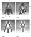
Figure 1 is a front view of a static cone splitter according to an embodiment of one aspect of the invention; -
Figure 2 is an oblique cut-away view of the cone splitter shown inFigure 1 ; -
Figure 3 is a front cut-away view of the cone splitter shown inFigure 1 ; -
Figure 4 is a side cut-away view of the cone splitter shown inFigure 1 ; -
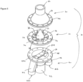
Figure 5 is an assembly view of the cone splitter shown inFigure 1 ; -
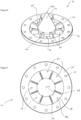
Figure 6 is an enlarged isometric view of the cone member of the cone splitter shown inFigure 5 ; -
Figure 7 is an enlarged plan view of the cone member shown inFigure 6 ; and -
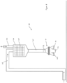
Figure 8 illustrates a sample collection system according to an embodiment of another aspect of the invention. - As shown in the Figures, a
static cone splitter 10 in accordance with an embodiment of the invention includes anupper housing 20, acone member 30 and alower housing 40. Theupper housing 20,cone member 30 andlower housing 40 are assembled so that in use of the cone splitter 10 a material stream enters thecone splitter 10 via aninlet 22 of theupper housing 20. As illustrated,inlet 22 has a circular cross-sectional configuration, although other configurations are envisaged. - The
cone member 30 includes a slant surface established on a central cone shaped component 32 (hereafter referred to as cone 32), eightblades 34 and aflange 36. The eightblades 34 define, at least in part, eightdifferent openings 38. - In accordance with the illustrated embodiment of the invention, the material stream enters the
cone splitter 10 and is then divided into six waste streams and two sub-sample streams. The six waste streams join together below thecone member 30 after passing through their respective opening and exit the cone splitter viaoutlet tube 42. Each sub-sample stream exits via a respectivesample outlet tube Figure 1 ,sample outlet tube 44 is located to the left of theoutlet tube 42 andsample outlet tube 46 is located to the right of theoutlet tube 42. Thesample outlet tubes outlet tube 42 so as to establish a symmetrical configuration. -
Sample outlet tube 44 has an upper opening 44a and alower opening 44b.Sample outlet tube 46 has an upper opening 46a and alower opening 46b. The shape of the upper opening 44a, 46a of each of thesample outlet tubes Figure 5 . - In use of the
cone splitter 10,outlet tube 42 of thelower housing 40 may be connected to appropriate pipework to enable the waste stream to be appropriately dealt with. Alternatively,outlet tube 42 may dispense the waste stream to the ground, a container or other reservoir. Similarly, the first and secondsample outlet tubes lower housing 40 may be connected to appropriate pipework to enable collection of the respective sub-sample stream. Alternatively, eachsample outlet tube - When the
upper housing 20,cone member 30 andlower housing 40 are assembled together, theflange 36 of thecone member 30 is located between a flange 24 of theupper housing 20 and aflange 48 of thelower housing 40. Bolts (not shown) pass through respective alignedapertures 50 in therespective flanges - In use, the
cone member 30 is orientated so that an apex ortip 32a of thecone 32 is located upwardly in the direction of theinlet tube 22. The apex ortip 32a may be pointed or rounded with a small radius (e.g. 1.5mm radius). The longitudinal central axis of thecone 32 is also coincident with the longitudinal central axis of theinlet tube 22 of theupper housing 20. - The
cone 32 of thecone member 30 and the interior wall 20a of theupper housing 20 establish a chamber C above theblades 34. This chamber C is best illustrated inFigures 3 and 4 and has an annular shape. As illustrated, the interior wall 20a bounding the chamber C extends substantially parallel to the plane of the slant surface of thecone 32 at any point thereabout. This configuration ensures that any portion of the material stream is not inadvertently entrained within the chamber C. - The
cone 32 has a base diameter larger than the diameter of theinlet 22 of theupper housing 20 so that all of the material stream flowing into the interior of thecone splitter 10 via theinlet 22 will be directed onto and will come into contact with some portion of the slant surface of thecone 32. - It is preferable to establish the cone angle of the
cone 32 as high as possible to reduce back pressure within the chamber C of thecone splitter 10. - As best shown in
Figure 7 , the eightblades 34 extend radially of the longitudinal central axis of thecone 32. Theblades 34 are equally spaced around thecone 32 and are angled so as to intersect the flow of the material stream substantially perpendicularly. This perpendicular intersection is shown inFigure 3 . - After contacting a portion of the slant surface of the
cone 32, the flow of the material stream is redirected and then passes through theopenings 38 located between theadjacent blades 34 of thecone member 30. Accordingly, theblades 34 divide the material stream into eight equally sized parts or sub-streams and thus 12.5% of the material stream will pass through each of theopenings 38. - As shown, each opening 38 is bounded by the associated
adjacent blades 34, apart 32b of the base of thecone 32, and a part 36a of theflange 36. The planar shape of theopenings 38 as viewed from above is best illustrated inFigure 7 . As clearly shown, the shape and size of each opening is identical. - It should be noted from
Figure 5 , that the upper opening 44a, 46a of each of the first and secondsample outlet tubes openings 38. Further, when theflange 36 of thecone member 30 is located on theflange 48 of thelower housing 40, the upper openings 44a, 46a of thesample outlet tubes openings 38 of thecone member 30. Theseparticular openings 38 are thus referred to hereafter as the sub-sample openings. Accordingly, during use of the illustratedcone splitter 10, any portion of the sample stream that passes through the sub-sample openings is diverted to the respective alignedsample outlet tubes - It will be appreciated by a person skilled in that art that the arrangement disclosed ensures that the flow resistance of the portions of the material stream about the slant surface of the
cone member 30 at entry to theopenings 38 is arranged to be substantially equal. Accordingly, the flow characteristic of the material stream at entry through theopenings 38 is substantially identical and thus an unbiased sample of the total material stream will flow for collection via the sub-sample openings into thesample outlet tubes - In accordance with the illustrated embodiment, two sub-samples each representative of 12.5% of the total material stream can be simultaneously collected with the remaining 75% ultimately divested to the
outlet tube 42. However, it will be appreciated that different configurations are possible. For example, only a single sample outlet tube may be provided and/or the number of blades of the cone member can be varied to correspondingly vary the percentage of the sub-sample flow actually collected by the or each of the sample outlet tubes of the cone splitter. -
Figure 8 illustrates asample collection system 100 in accordance with an embodiment of the invention. Thesample collection system 100 includes pipework 105 through which a material stream is arranged to flow, a chamber 110 fitted with a course screen 115, a valve arrangement 120, a chamber exit pipe 125, and astatic cone splitter 10. Thestatic cone splitter 10 of this embodiment adopts the form described previously in connection withFigures 1 to 7 . - As illustrated in
Figure 8 , the chamber 110 is connected via the chamber exit pipe 125 to theinlet tube 22 of thestatic cone splitter 10. The chamber 110 is located substantially vertically above thestatic cone splitter 10 and is of a larger diameter than the diameter of the exit pipe 125. Chamber 110 is arranged to collect the material stream prior to it flowing into thecone splitter 10. - The chamber 110 includes the course screen 115 which is capable of screening out oversize material contained in the material stream that would otherwise block flow through the
cone splitter 10. The screen 115 would be removable for cleaning. The use of other arrangements to screen out oversize material from the material stream is envisaged. Further, it is envisaged that such screening arrangements may be excluded. - The chamber 110 has a base 102 which adopts a conical shape to prevent build-up of particulate material thereon. Other base configurations are envisaged.
- Valve arrangement 120 is located at the top 104 of the
chamber 100 and distal from thecone splitter 10. The valve arrangement 120 is configured to enable the break of any vacuum established within thesystem 100 and to provide a discharge point for excess material stream in the event that the flow rate through thesystem 100 is too high to be handled by the chamber 110. In accordance with an embodiment of the invention the valve arrangement 120 includes an air valve. - The
sample collection system 100 is preferably arranged to receive the material stream at an operating flow rate greater than about 60 litres per minute and up to about 150 litres per minutes. The upper flow rate limit of the system according to the described embodiment of the invention is generally limited to a rate at which back pressure on the bore hole and the equipment is less than about 1 Bar. - The relative diameters of the chamber 110 and exit pipe 125 and the location of the valve arrangement 120 at the top of the
chamber 100 allows material stream to flow through the chamber 110 and into thecone splitter 10, with any vacuum broken and without excess air being drawn into the chamber 110. This is because the air flowing via the valve arrangement 120 is not in direct contact with the material stream. - The length direction of the exit pipe 125 from the chamber 110 extends substantially vertically and directs the material stream into the
inlet tube 22 of thestatic cone splitter 10. The exit pipe 125 is a short vertical pipe with a length of approximately 300mm. This compares with a chamber 110 having a diameter of about 200mm and a height of about 300mm. - During operation of the
system 100, the material stream from a drilling operation is fed via pipework 105 into the chamber 110. The chamber 110 is located generally vertically above and centrally of theinlet 22 of theupper housing 20 of thecone splitter 10. Preferably, the material stream is supplied at a flow rate of greater than about 60 litres per minute. This ensures that there is always a substantially constant and uniform distribution of liquid and cuttings in the material stream when it enters theinlet 22 of thecone splitter 20. - Embodiments of the invention are advantageous because they enable collection of a non-biased sample of a material stream. Further, the system does not include any moving parts and thus the system is less likely to break down. Further, the system requires no external power supply to operate. If the
cone 32 of thestatic cone splitter 10 becomes damaged, thecone member 30 can be easily and quickly replaced and thus down time for the system is only minor. - Embodiments of the invention are capable of collecting smaller sample sizes (i.e. a smaller percentage of the total material stream) and are not flow rate dependent. Further, embodiments of the invention enable reliable sampling of a material stream with greater than 90% liquid, such as that generated in coiled tubing drilling.
- The embodiments have been described by way of example only and modifications within the scope of the appended claims are envisaged.
Claims (15)
- A sample collection system (100) for collecting sub-samples from a material stream, said system including a valve arrangement (120) and a static cone splitter (10), and wherein the valve arrangement (120) is arranged to enable operation of the static cone splitter (10) to collect a non-biased sample of the material stream fed to the static cone splitter (10) under first and second operational conditions, the first operational condition requiring the material stream to be at substantially atmospheric pressure and flowing at a minimum functional flow rate, and the second operational condition requiring the material stream to be pressurised above atmospheric pressure and at a flow rate higher than the minimum functional flow rate, characterized in that the valve arrangement (120) includes an air valve which, at the minimum functional flow rate of the material stream, remains open allowing air to enter the valve arrangement to allow the material stream to flow without restriction at substantially atmospheric pressure, wherein at flow rates higher than the minimum functional flow rate the air valve is arranged to allow the evacuation of air from the system until the system is full of material stream at which point the air valve closes.
- The sample collection system according to claim 1, wherein the valve arrangement (120) is a passive component that operates automatically dependant on the flow rate of the material stream.
- The sample collection system according to claim 1 or 2, further including a chamber (110), and wherein the material stream is arranged to flow into the chamber (110) before entry into the static cone splitter (10), and further wherein the valve arrangement (120) is preferably connected to the chamber distal from the cone splitter (10).
- The sample collection system according to claim 3, wherein the cone splitter (10) is located substantially vertically below the chamber (110) and is connected thereto by a substantially vertical chamber exit pipe, wherein the vertical chamber exit pipe preferably connects to an inlet tube of the static cone splitter (10), and further wherein the inlet tube preferably has a cross-sectional flow area sized such that the unrestricted flow by gravity of the material stream through the inlet tube is substantially equal to or less than the minimum functional flow rate of the system (100).
- The sample collection system according to any one of claims 1 to 4, configured to receive the material stream at a flow rate of greater than about 60 litres per minute.
- The sample collection system according to any one of claims 1 to 5, wherein the static cone splitter (10) includes an upper housing (20), a cone member (30) and a lower housing (40), the cone member (30) including a slant surface and at least two blades, said at least two blades (34) defining at least in part a first and a second opening (38) of equal flow area, the first opening being a sub-sample opening and the second opening being a waste opening, wherein the cone splitter is configured so that in use the material stream entering the upper housing (20) is directed into contact with the slant surface and then a portion of the material stream after contacting the slant surface is directed through the sub-sample opening and is arranged to exit from the cone splitter (10) via a sample outlet tube (44, 46), the remaining material stream forming a waste stream which is directed through said waste opening, and the flow resistance of the portions of the material stream about the slant surface at entry into the openings is substantially equal.
- The sample collection system according to claim 6, wherein the slant surface is established by or formed on a cone shaped component.
- The sample collection system according to claim 7, including a cone shaped component located centrally of the cone member (30).
- The sample collection system according to any of claims 6 to 8, wherein the upper housing (20) includes an inlet tube through which the material stream is arranged to pass and the longitudinal central axis of the inlet tube is centrally aligned with the longitudinal central axis of the cone member (30) so that the entire material stream entering the upper housing is directed into contact with the slant surface.
- The sample collection system according to claim 9, the inlet tube having a circular cross-sectional configuration of a diameter less than a base diameter of the slant surface.
- The sample collection system according to claim 9 or 10, wherein the blades of the cone member (30) extend radially outwardly of the longitudinal central axis of the cone shaped component and each blade is configured so as to intersect the flow of the material stream substantially perpendicularly.
- The sample collection system according to claim 11, wherein the blades are spaced about the cone shaped component so that the openings (38) therebetween are of equal flow area, and preferably wherein the openings (38) have substantially the same planar cross-sectional configuration in the direction of flow.
- The sample collection system according to any one of claims 6 to 12, wherein each blade (34) is identical in size and shape, and/or wherein the openings (38) are dimensioned such that the minimum opening dimension is at least three times the maximum dimension of the largest particle size expected in the material stream, and/or wherein eight blades (34) are provided so as to divide the material stream into eight equally sized sub-streams each containing 12.5% of the material stream.
- The sample collection system according to any one of claims 6 to 13, including two sample outlets (44, 46) each for collecting a single sub-sample.
- The sample collection system according to any one of claims 6 to 14, including a waste outlet with a cross-sectional area such that the unrestricted flow due to gravity through the waste outlet is greater than 75% of the minimum functional flow rate of the sample stream.
Applications Claiming Priority (2)
| Application Number | Priority Date | Filing Date | Title |
|---|---|---|---|
| AU2017903541A AU2017903541A0 (en) | 2017-09-01 | Sample collection system and parts thereof | |
| PCT/AU2018/050938 WO2019040990A1 (en) | 2017-09-01 | 2018-08-31 | Sample collection system and parts thereof |
Publications (3)
| Publication Number | Publication Date |
|---|---|
| EP3676592A1 EP3676592A1 (en) | 2020-07-08 |
| EP3676592A4 EP3676592A4 (en) | 2021-08-11 |
| EP3676592B1 true EP3676592B1 (en) | 2023-09-27 |
Family
ID=65524596
Family Applications (1)
| Application Number | Title | Priority Date | Filing Date |
|---|---|---|---|
| EP18850114.2A Active EP3676592B1 (en) | 2017-09-01 | 2018-08-31 | Sample collection system and parts thereof |
Country Status (8)
| Country | Link |
|---|---|
| US (1) | US11614383B2 (en) |
| EP (1) | EP3676592B1 (en) |
| CN (1) | CN111065905B (en) |
| AU (1) | AU2018326394B2 (en) |
| CA (1) | CA3072962C (en) |
| CL (1) | CL2020000496A1 (en) |
| WO (1) | WO2019040990A1 (en) |
| ZA (1) | ZA202000787B (en) |
Families Citing this family (1)
| Publication number | Priority date | Publication date | Assignee | Title |
|---|---|---|---|---|
| WO2023193051A1 (en) * | 2022-04-04 | 2023-10-12 | Tribe Technology Pty Ltd | A sampling apparatus and a splitter assembly |
Family Cites Families (13)
| Publication number | Priority date | Publication date | Assignee | Title |
|---|---|---|---|---|
| US3754715A (en) * | 1971-08-16 | 1973-08-28 | D Udy | Method and means for size reduction and collection of solid materials |
| US4672856A (en) | 1986-06-20 | 1987-06-16 | Weyerhaeuser Company | Sample splitter |
| DE3637757A1 (en) | 1986-11-05 | 1988-05-11 | Krupp Polysius Ag | SAMPLE DIVIDER |
| FR2617963B1 (en) * | 1987-07-10 | 1991-12-06 | Cohen Daniel | METHOD AND DEVICE FOR DISTRIBUTING A PRIMARY VOLUME OF A FLUID ADVANTAGEOUSLY A LIQUID, INTO A DETERMINED NUMBER OF SECONDARY VOLUMES HAVING A PREDEFINED RELATIONSHIP BETWEEN THEM, BY USING SYMMETRICALLY DISTRIBUTED DRAINAGE VENTS -MEME SYMETRIC |
| US5426987A (en) | 1994-02-01 | 1995-06-27 | B3 Systems, Inc. | Apparatus for collecting small samples from flowable solids |
| AU2499095A (en) | 1994-07-18 | 1996-02-01 | Quinncorp Pty Ltd | Slurry sampler |
| DE69629824T2 (en) * | 1996-11-29 | 2004-07-15 | S.E.G. Mekanik Ab | Mass flow measuring device |
| CN1871503A (en) * | 2003-10-21 | 2006-11-29 | Sds金属工艺有限公司 | An improved rotary sample collector |
| US8020459B2 (en) | 2006-11-08 | 2011-09-20 | Sandivk Mining and Construction Australia (Production/Suppy) Pty Ltd | Sampling apparatus |
| US20110023633A1 (en) | 2008-04-16 | 2011-02-03 | Foss Analytical Ab | Sample divider |
| AU2010300084B2 (en) * | 2009-09-22 | 2016-11-10 | Toby Adam Lennox Day | Sample collection apparatus |
| US9366602B2 (en) | 2013-06-18 | 2016-06-14 | Jason K. Diehl | Particulate material sample divider |
| CN105181396B (en) * | 2015-09-11 | 2018-05-15 | 北京市化工职业病防治院 | A kind of personal breathing dust sampling device |
-
2018
- 2018-08-31 WO PCT/AU2018/050938 patent/WO2019040990A1/en unknown
- 2018-08-31 CA CA3072962A patent/CA3072962C/en active Active
- 2018-08-31 US US15/733,016 patent/US11614383B2/en active Active
- 2018-08-31 EP EP18850114.2A patent/EP3676592B1/en active Active
- 2018-08-31 CN CN201880056920.1A patent/CN111065905B/en active Active
- 2018-08-31 AU AU2018326394A patent/AU2018326394B2/en active Active
-
2020
- 2020-02-06 ZA ZA2020/00787A patent/ZA202000787B/en unknown
- 2020-02-28 CL CL2020000496A patent/CL2020000496A1/en unknown
Also Published As
| Publication number | Publication date |
|---|---|
| ZA202000787B (en) | 2021-10-27 |
| CN111065905A (en) | 2020-04-24 |
| US20200182749A1 (en) | 2020-06-11 |
| CL2020000496A1 (en) | 2020-06-19 |
| US11614383B2 (en) | 2023-03-28 |
| EP3676592A4 (en) | 2021-08-11 |
| CA3072962A1 (en) | 2019-03-07 |
| CN111065905B (en) | 2023-05-09 |
| EP3676592A1 (en) | 2020-07-08 |
| AU2018326394A1 (en) | 2020-02-20 |
| CA3072962C (en) | 2024-04-30 |
| AU2018326394B2 (en) | 2023-08-31 |
| WO2019040990A1 (en) | 2019-03-07 |
Similar Documents
| Publication | Publication Date | Title |
|---|---|---|
| US4689052A (en) | Virtual impactor | |
| US4860591A (en) | Gas-liquid separation and flow measurement apparatus | |
| CA1324595C (en) | Centrifugal separator | |
| CN107694217A (en) | Gas-liquid separator | |
| US7439075B2 (en) | Method and device for withdrawing suspended microparticles from a fluidic microsystem | |
| EP3676592B1 (en) | Sample collection system and parts thereof | |
| US4274846A (en) | Particle sizing sampler | |
| CN103068456A (en) | Particulate matter monitor | |
| NL8000564A (en) | METHOD AND APPARATUS FOR SAMPLING A FLUID FLOWING FROM A WELL | |
| JP2017053859A (en) | Exhaust gas sampling system including mixer to mix exhaust gas and dilution gas | |
| US5426987A (en) | Apparatus for collecting small samples from flowable solids | |
| KR101793982B1 (en) | Gas dilution device | |
| US6286376B1 (en) | Sampling of a mixture to be analyzed for particle size/particle size distribution | |
| US4524628A (en) | In line dry material sampler | |
| US10124353B1 (en) | Apparatus for deagglomerating and disseminating powders and particulate matter | |
| US6444001B1 (en) | Separator and separator system | |
| CA2472749C (en) | Method and apparatus for taking slurry samples | |
| GB2357710A (en) | Mixing oil in a transfer line prior to sampling | |
| EP2425890B1 (en) | Flow Conditioning Apparatus | |
| AT503587B1 (en) | SUCTION DEVICE FOR FINE DISTRIBUTED SUBSTANCES | |
| US6544312B2 (en) | Device for separating the particle-size spectrum of a polydisperse aerosol | |
| US10145764B2 (en) | Continuous flow sampling apparatus having an opening and first and second slide doors for closing the opening | |
| EA036167B1 (en) | Extraction cell for a centrifugal partition chromatograph, centrifugal partition chromatograph containing such a cell, and method for producing such an extraction cell | |
| US20220331756A1 (en) | Smart entrainment atomisation mixing system | |
| US4722746A (en) | Variable volume sampler for aerosols and gases |
Legal Events
| Date | Code | Title | Description |
|---|---|---|---|
| STAA | Information on the status of an ep patent application or granted ep patent |
Free format text: STATUS: THE INTERNATIONAL PUBLICATION HAS BEEN MADE |
|
| PUAI | Public reference made under article 153(3) epc to a published international application that has entered the european phase |
Free format text: ORIGINAL CODE: 0009012 |
|
| STAA | Information on the status of an ep patent application or granted ep patent |
Free format text: STATUS: REQUEST FOR EXAMINATION WAS MADE |
|
| 17P | Request for examination filed |
Effective date: 20200325 |
|
| AK | Designated contracting states |
Kind code of ref document: A1 Designated state(s): AL AT BE BG CH CY CZ DE DK EE ES FI FR GB GR HR HU IE IS IT LI LT LU LV MC MK MT NL NO PL PT RO RS SE SI SK SM TR |
|
| AX | Request for extension of the european patent |
Extension state: BA ME |
|
| DAV | Request for validation of the european patent (deleted) | ||
| DAX | Request for extension of the european patent (deleted) | ||
| RIC1 | Information provided on ipc code assigned before grant |
Ipc: G01N 1/20 20060101AFI20210331BHEP Ipc: G01N 1/18 20060101ALI20210331BHEP |
|
| A4 | Supplementary search report drawn up and despatched |
Effective date: 20210709 |
|
| RIC1 | Information provided on ipc code assigned before grant |
Ipc: G01N 1/20 20060101AFI20210705BHEP Ipc: G01N 1/18 20060101ALI20210705BHEP |
|
| GRAP | Despatch of communication of intention to grant a patent |
Free format text: ORIGINAL CODE: EPIDOSNIGR1 |
|
| STAA | Information on the status of an ep patent application or granted ep patent |
Free format text: STATUS: GRANT OF PATENT IS INTENDED |
|
| INTG | Intention to grant announced |
Effective date: 20230414 |
|
| P01 | Opt-out of the competence of the unified patent court (upc) registered |
Effective date: 20230424 |
|
| GRAS | Grant fee paid |
Free format text: ORIGINAL CODE: EPIDOSNIGR3 |
|
| GRAA | (expected) grant |
Free format text: ORIGINAL CODE: 0009210 |
|
| STAA | Information on the status of an ep patent application or granted ep patent |
Free format text: STATUS: THE PATENT HAS BEEN GRANTED |
|
| AK | Designated contracting states |
Kind code of ref document: B1 Designated state(s): AL AT BE BG CH CY CZ DE DK EE ES FI FR GB GR HR HU IE IS IT LI LT LU LV MC MK MT NL NO PL PT RO RS SE SI SK SM TR |
|
| REG | Reference to a national code |
Ref country code: GB Ref legal event code: FG4D |
|
| REG | Reference to a national code |
Ref country code: CH Ref legal event code: EP |
|
| REG | Reference to a national code |
Ref country code: DE Ref legal event code: R096 Ref document number: 602018058416 Country of ref document: DE |
|
| REG | Reference to a national code |
Ref country code: IE Ref legal event code: FG4D |
|
| REG | Reference to a national code |
Ref country code: LT Ref legal event code: MG9D |
|
| PG25 | Lapsed in a contracting state [announced via postgrant information from national office to epo] |
Ref country code: GR Free format text: LAPSE BECAUSE OF FAILURE TO SUBMIT A TRANSLATION OF THE DESCRIPTION OR TO PAY THE FEE WITHIN THE PRESCRIBED TIME-LIMIT Effective date: 20231228 |
|
| PG25 | Lapsed in a contracting state [announced via postgrant information from national office to epo] |
Ref country code: SE Free format text: LAPSE BECAUSE OF FAILURE TO SUBMIT A TRANSLATION OF THE DESCRIPTION OR TO PAY THE FEE WITHIN THE PRESCRIBED TIME-LIMIT Effective date: 20230927 Ref country code: RS Free format text: LAPSE BECAUSE OF FAILURE TO SUBMIT A TRANSLATION OF THE DESCRIPTION OR TO PAY THE FEE WITHIN THE PRESCRIBED TIME-LIMIT Effective date: 20230927 Ref country code: NO Free format text: LAPSE BECAUSE OF FAILURE TO SUBMIT A TRANSLATION OF THE DESCRIPTION OR TO PAY THE FEE WITHIN THE PRESCRIBED TIME-LIMIT Effective date: 20231227 Ref country code: LV Free format text: LAPSE BECAUSE OF FAILURE TO SUBMIT A TRANSLATION OF THE DESCRIPTION OR TO PAY THE FEE WITHIN THE PRESCRIBED TIME-LIMIT Effective date: 20230927 Ref country code: LT Free format text: LAPSE BECAUSE OF FAILURE TO SUBMIT A TRANSLATION OF THE DESCRIPTION OR TO PAY THE FEE WITHIN THE PRESCRIBED TIME-LIMIT Effective date: 20230927 Ref country code: HR Free format text: LAPSE BECAUSE OF FAILURE TO SUBMIT A TRANSLATION OF THE DESCRIPTION OR TO PAY THE FEE WITHIN THE PRESCRIBED TIME-LIMIT Effective date: 20230927 Ref country code: GR Free format text: LAPSE BECAUSE OF FAILURE TO SUBMIT A TRANSLATION OF THE DESCRIPTION OR TO PAY THE FEE WITHIN THE PRESCRIBED TIME-LIMIT Effective date: 20231228 Ref country code: FI Free format text: LAPSE BECAUSE OF FAILURE TO SUBMIT A TRANSLATION OF THE DESCRIPTION OR TO PAY THE FEE WITHIN THE PRESCRIBED TIME-LIMIT Effective date: 20230927 |
|
| REG | Reference to a national code |
Ref country code: NL Ref legal event code: MP Effective date: 20230927 |
|
| REG | Reference to a national code |
Ref country code: AT Ref legal event code: MK05 Ref document number: 1615844 Country of ref document: AT Kind code of ref document: T Effective date: 20230927 |
|
| PG25 | Lapsed in a contracting state [announced via postgrant information from national office to epo] |
Ref country code: NL Free format text: LAPSE BECAUSE OF FAILURE TO SUBMIT A TRANSLATION OF THE DESCRIPTION OR TO PAY THE FEE WITHIN THE PRESCRIBED TIME-LIMIT Effective date: 20230927 |
|
| PG25 | Lapsed in a contracting state [announced via postgrant information from national office to epo] |
Ref country code: IS Free format text: LAPSE BECAUSE OF FAILURE TO SUBMIT A TRANSLATION OF THE DESCRIPTION OR TO PAY THE FEE WITHIN THE PRESCRIBED TIME-LIMIT Effective date: 20240127 |
|
| PG25 | Lapsed in a contracting state [announced via postgrant information from national office to epo] |
Ref country code: AT Free format text: LAPSE BECAUSE OF FAILURE TO SUBMIT A TRANSLATION OF THE DESCRIPTION OR TO PAY THE FEE WITHIN THE PRESCRIBED TIME-LIMIT Effective date: 20230927 |
|
| PG25 | Lapsed in a contracting state [announced via postgrant information from national office to epo] |
Ref country code: ES Free format text: LAPSE BECAUSE OF FAILURE TO SUBMIT A TRANSLATION OF THE DESCRIPTION OR TO PAY THE FEE WITHIN THE PRESCRIBED TIME-LIMIT Effective date: 20230927 |
|
| PG25 | Lapsed in a contracting state [announced via postgrant information from national office to epo] |
Ref country code: SM Free format text: LAPSE BECAUSE OF FAILURE TO SUBMIT A TRANSLATION OF THE DESCRIPTION OR TO PAY THE FEE WITHIN THE PRESCRIBED TIME-LIMIT Effective date: 20230927 Ref country code: RO Free format text: LAPSE BECAUSE OF FAILURE TO SUBMIT A TRANSLATION OF THE DESCRIPTION OR TO PAY THE FEE WITHIN THE PRESCRIBED TIME-LIMIT Effective date: 20230927 Ref country code: IS Free format text: LAPSE BECAUSE OF FAILURE TO SUBMIT A TRANSLATION OF THE DESCRIPTION OR TO PAY THE FEE WITHIN THE PRESCRIBED TIME-LIMIT Effective date: 20240127 Ref country code: ES Free format text: LAPSE BECAUSE OF FAILURE TO SUBMIT A TRANSLATION OF THE DESCRIPTION OR TO PAY THE FEE WITHIN THE PRESCRIBED TIME-LIMIT Effective date: 20230927 Ref country code: EE Free format text: LAPSE BECAUSE OF FAILURE TO SUBMIT A TRANSLATION OF THE DESCRIPTION OR TO PAY THE FEE WITHIN THE PRESCRIBED TIME-LIMIT Effective date: 20230927 Ref country code: CZ Free format text: LAPSE BECAUSE OF FAILURE TO SUBMIT A TRANSLATION OF THE DESCRIPTION OR TO PAY THE FEE WITHIN THE PRESCRIBED TIME-LIMIT Effective date: 20230927 Ref country code: AT Free format text: LAPSE BECAUSE OF FAILURE TO SUBMIT A TRANSLATION OF THE DESCRIPTION OR TO PAY THE FEE WITHIN THE PRESCRIBED TIME-LIMIT Effective date: 20230927 Ref country code: PT Free format text: LAPSE BECAUSE OF FAILURE TO SUBMIT A TRANSLATION OF THE DESCRIPTION OR TO PAY THE FEE WITHIN THE PRESCRIBED TIME-LIMIT Effective date: 20240129 Ref country code: SK Free format text: LAPSE BECAUSE OF FAILURE TO SUBMIT A TRANSLATION OF THE DESCRIPTION OR TO PAY THE FEE WITHIN THE PRESCRIBED TIME-LIMIT Effective date: 20230927 |