EP3676552B1 - Automatic quick response temperature measurement for rotary kilns - Google Patents
Automatic quick response temperature measurement for rotary kilns Download PDFInfo
- Publication number
- EP3676552B1 EP3676552B1 EP18746911.9A EP18746911A EP3676552B1 EP 3676552 B1 EP3676552 B1 EP 3676552B1 EP 18746911 A EP18746911 A EP 18746911A EP 3676552 B1 EP3676552 B1 EP 3676552B1
- Authority
- EP
- European Patent Office
- Prior art keywords
- thermocouple
- hollow body
- elongated hollow
- rotary kiln
- drive
- Prior art date
- Legal status (The legal status is an assumption and is not a legal conclusion. Google has not performed a legal analysis and makes no representation as to the accuracy of the status listed.)
- Active
Links
Images


Classifications
-
- G—PHYSICS
- G01—MEASURING; TESTING
- G01K—MEASURING TEMPERATURE; MEASURING QUANTITY OF HEAT; THERMALLY-SENSITIVE ELEMENTS NOT OTHERWISE PROVIDED FOR
- G01K1/00—Details of thermometers not specially adapted for particular types of thermometer
- G01K1/14—Supports; Fastening devices; Arrangements for mounting thermometers in particular locations
- G01K1/146—Supports; Fastening devices; Arrangements for mounting thermometers in particular locations arrangements for moving thermometers to or from a measuring position
-
- F—MECHANICAL ENGINEERING; LIGHTING; HEATING; WEAPONS; BLASTING
- F27—FURNACES; KILNS; OVENS; RETORTS
- F27B—FURNACES, KILNS, OVENS OR RETORTS IN GENERAL; OPEN SINTERING OR LIKE APPARATUS
- F27B7/00—Rotary-drum furnaces, i.e. horizontal or slightly inclined
- F27B7/20—Details, accessories or equipment specially adapted for rotary-drum furnaces
- F27B7/42—Arrangement of controlling, monitoring, alarm or like devices
-
- F—MECHANICAL ENGINEERING; LIGHTING; HEATING; WEAPONS; BLASTING
- F27—FURNACES; KILNS; OVENS; RETORTS
- F27D—DETAILS OR ACCESSORIES OF FURNACES, KILNS, OVENS OR RETORTS, IN SO FAR AS THEY ARE OF KINDS OCCURRING IN MORE THAN ONE KIND OF FURNACE
- F27D19/00—Arrangements of controlling devices
-
- F—MECHANICAL ENGINEERING; LIGHTING; HEATING; WEAPONS; BLASTING
- F27—FURNACES; KILNS; OVENS; RETORTS
- F27D—DETAILS OR ACCESSORIES OF FURNACES, KILNS, OVENS OR RETORTS, IN SO FAR AS THEY ARE OF KINDS OCCURRING IN MORE THAN ONE KIND OF FURNACE
- F27D21/00—Arrangement of monitoring devices; Arrangement of safety devices
- F27D21/0014—Devices for monitoring temperature
-
- G—PHYSICS
- G01—MEASURING; TESTING
- G01K—MEASURING TEMPERATURE; MEASURING QUANTITY OF HEAT; THERMALLY-SENSITIVE ELEMENTS NOT OTHERWISE PROVIDED FOR
- G01K13/00—Thermometers specially adapted for specific purposes
- G01K13/04—Thermometers specially adapted for specific purposes for measuring temperature of moving solid bodies
- G01K13/08—Thermometers specially adapted for specific purposes for measuring temperature of moving solid bodies in rotary movement
-
- G—PHYSICS
- G01—MEASURING; TESTING
- G01K—MEASURING TEMPERATURE; MEASURING QUANTITY OF HEAT; THERMALLY-SENSITIVE ELEMENTS NOT OTHERWISE PROVIDED FOR
- G01K7/00—Measuring temperature based on the use of electric or magnetic elements directly sensitive to heat ; Power supply therefor, e.g. using thermoelectric elements
- G01K7/02—Measuring temperature based on the use of electric or magnetic elements directly sensitive to heat ; Power supply therefor, e.g. using thermoelectric elements using thermoelectric elements, e.g. thermocouples
-
- F—MECHANICAL ENGINEERING; LIGHTING; HEATING; WEAPONS; BLASTING
- F27—FURNACES; KILNS; OVENS; RETORTS
- F27D—DETAILS OR ACCESSORIES OF FURNACES, KILNS, OVENS OR RETORTS, IN SO FAR AS THEY ARE OF KINDS OCCURRING IN MORE THAN ONE KIND OF FURNACE
- F27D19/00—Arrangements of controlling devices
- F27D2019/0006—Monitoring the characteristics (composition, quantities, temperature, pressure) of at least one of the gases of the kiln atmosphere and using it as a controlling value
- F27D2019/0018—Monitoring the temperature of the atmosphere of the kiln
-
- F—MECHANICAL ENGINEERING; LIGHTING; HEATING; WEAPONS; BLASTING
- F27—FURNACES; KILNS; OVENS; RETORTS
- F27D—DETAILS OR ACCESSORIES OF FURNACES, KILNS, OVENS OR RETORTS, IN SO FAR AS THEY ARE OF KINDS OCCURRING IN MORE THAN ONE KIND OF FURNACE
- F27D19/00—Arrangements of controlling devices
- F27D2019/0028—Regulation
- F27D2019/0059—Regulation involving the control of the conveyor movement, e.g. speed or sequences
Definitions
- the invention is directed to a device for measuring the temperature in a rotary kiln through which material passes being heated to elevated temperatures.
- This invention also covers a rotary kiln equipped with said device and a process for measuring the inside temperature of the rotary kiln in situ.
- Temperature measurements are of particular importance for each process control. Especially for continuous processes, these measurements have to be local and time resolved. For a rotary kiln, a pyroprocessing device used to thermally treat solid materials at high to extremely high temperatures (calcination or direct reduction) in a continuous process, such measurement is particularly challenging.
- thermocouples mostly thermoelectric pyrometers
- radiation pyrometers are fixed on the kiln's shell.
- the thermocouples are moved in and out of the rotary kiln's interior manually during operation of the rotary kiln.
- thermocouple for quick response temperature measurement is manually executed during operation at the rotating kiln. That causes many risks of injuries for the operating personnel due to the rotary movement of the kiln and is therefore no longer acceptable according to current occupational health and safety regulations.
- the most critical step is the breakthrough of the accretions inside the kiln. They can be very hard and thick, depending on process parameters and the position in the kiln.
- a drive unit (21) drives an elongated hollow body (4) together with a thermocouple (3) in and out of the kiln.
- a slotting skewer (3) is inserted into the kiln and goes in and out of the kiln for removing accretions in front of the opening, the rotation of shaft (9) enables a thermocouple (5) to come in front of the opening and the thermocouple (5) is inserted into the kiln for temperature measurement.
- a slotting skewer (3) is inserted into the kiln and goes in and out of the kiln for removing accretions in front of the opening, a lateral/horizontal translation of the backplate (1) enables a thermocouple (5) to come in front of the opening and the thermocouple (5) is inserted into the kiln for temperature measurement.
- the invention provides a device for measuring the temperature in a rotary kiln through which material passes being heated to elevated temperatures.
- the device features a drive as well as an elongated hollow body with means to fix a thermocouple.
- the drive and the elongated hollow body are mounted such that they rotate jointly with the rotary kiln. Further, the drive can move the elongated hollow body together with thermocouple through an opening in and out of the rotary kiln's interior for measuring the temperature inside the rotary kiln during operation.
- the invention offers the advantage that no manual work has to be done at the kiln during operation, i.e. with the kiln rotating. That increases the work safety since an easy execution of the measurement procedure from the control room is possible.
- the whole device can be manually removed from the kiln shell and replaced by another device during short periods of interrupted kiln rotation. This makes the maintenance and repair works very easy and comfortable without long stops of the kiln.
- the elongated hollow body is tubular and/or the thermocouple can be mounted such that its measuring tip protrudes out of the elongated hollow body.
- the extension of the thermocouple measuring tip out of the elongated hollow body is of particular importance for a quick response temperature measurement in the rotary kiln since it was found that the solid material in the lower part of the rotary kiln and the gas in the upper part of the rotary kiln, the so-called free board above the solid material have different temperatures. Only with a high reaction speed of the temperature measurement the exact solid material and gas temperatures can be detected within one revolution.
- the position of the material can be determined by a sudden change in the temperature profile during one revolution (see figure 5 ). Such a sudden change cannot be detected if the measuring tip is covered with a protective layer like the protection pipe and/or the elongated hollow body, which is why the measuring tip has to be unshielded or only very weak protected during the measurement.
- thermocouple is designed according to the present invention such that it can be moved separately from the elongated hollow body in and out of the elongated hollow body.
- the elongated hollow body can be used completely separately, shielding the thermocouple measurement tip inside, to break a hole through the accretions on the inside diameter of the rotary kiln before the measurement itself is done by shifting the measuring tip of the thermocouple through the elongated hollow body by means of a mechanical actuator. In this way the measurement tip is protected from damages.
- the elongated hollow body is tapered at the side directed towards the rotary kiln.
- the elongated hollow body is made of heat resistant steel to ensure thermal and mechanical stability in equal measure.
- thermocouple an additional protection pipe between the elongated hollow body and the thermocouple is foreseen for additional protection and stabilization of the thermocouple.
- the elongated hollow body is mounted such that in the stand-by position it protects the thermocouple against wear caused by the solid material inside the rotary kiln and high temperatures/ temperature changes.
- the drive for the elongated hollow body and the actuator for the thermocouple are designed as electric motors, which can be operated very easily.
- electrical power is supplied to the cylindrical shell of the rotary kiln by means of slip rings.
- slip rings In many rotary kiln applications those slip rings already exist for other purposes and can, therefore, also be used for the drive of the elongated hollow body and for the actuator of the thermocouple.
- the movement of the drive is transmitted to the elongated hollow body and/or the thermocouple by means of at least one, preferably two worm wheels, driven by a worm, and moving up and down on threaded spindles.
- the use of two parallel spindles has the advantages of a guided movement.
- Using a worm and worm wheels has the advantage of an additional self-locking effect.
- thermocouples without any protection against wear and thermal shocks are used. That causes a very low durability and limited life-time of these thermocouples. Therefore, the thermocouples have to be exchanged frequently during operation.
- thermocouple exchange Two different ways of thermocouple exchange are described:
- thermocouple In both cases the accretions inside the rotary kiln in front of the thermocouple will be automatically broken by an elongated hollow body without any manual interaction and the thermocouple will be automatically moved between a measuring position and a stand-by position. In both cases, the rotary kiln has to be stopped to manually exchange the elongated hollow body in case of wear or damage. However, as per this invention, the elongated hollow body is fixed with a bayonet fitting for quick manual exchange.
- a magazine is foreseen to provide at least two, preferably at least six thermocouples.
- one thermocouple When one thermocouple is damaged, it will be automatically retracted inside the elongated hollow body, the magazine will be rotated by one position and a new thermocouple from the magazine will be inserted into the measurement position. So it is possible to avoid any direct manual interaction of operating personnel with the rotary kiln during operation.
- the magazine is manually exchangeable during short stoppages of the rotation of the rotary kiln. So the magazine can be replaced very fast and easy as a whole.
- the magazine is a drum magazine for a failure-free operation. Also a turret magazine is possible.
- the magazine is moved by a separate drive to achieve full automation, e.g. a Geneva drive.
- a separate drive e.g. a Geneva drive.
- an electric motor is preferred as a drive motor for the Geneva drive.
- the invention covers a rotary kiln, characterized in that at least one device for temperature measurement according to any of claims 1 to 10 is mounted on the shell of the rotary kiln.
- the device can be retrofitted to already existing rotary kilns very easily:
- the semi-automatic solution can be installed at the nozzle for the manual QRT measurements and only a few modifications like the installation of the flange at the kiln shell have to be done.
- the fully-automatic solution is designed for the nozzles of the sampling ports. For a complete modification of an existing plant more ports are needed at the kiln shell. The initialization of the measuring procedure and other control functions can be done in the control room.
- the shell temperatures are critical for this device. Additional to an insulation layer e.g. made of air chambers between base flange of the device and flange at the shell, a heat shield made of aluminum should be installed between kiln shell and flange, to protect it against thermal radiation. Furthermore a part of the air from the existing air injection fans can be taken to provide cooling air for the device. If no air injection fans exist, a new air fan can be installed to supply ambient cooling air. The fan can be driven by an electric motor also installed on the shell of the rotary kiln. The electric power for the drive can be provided by means of the slip rings also supplying electric power to the device described above.
- an insulation layer e.g. made of air chambers between base flange of the device and flange at the shell
- a heat shield made of aluminum should be installed between kiln shell and flange, to protect it against thermal radiation.
- a part of the air from the existing air injection fans can be taken to provide cooling air for the device. If no air injection fans exist,
- the invention covers also a method for temperature measurement in a rotary kiln with the features of claim 10.
- thermocouple protected by an elongated hollow body is moved into the interior of the rotary kiln.
- the thermocouple can be positioned for measurement through the elongated hollow body by means of an actuator in such a way, that the temperature sensitive tip of the thermocouple protrudes out of the interior (hot) end of the elongated hollow body.
- the same actuator can also retract the thermocouple back into the elongated hollow body to provide mechanical protection of the temperature sensitive tip of the thermocouple which is also very sensitive to wear and mechanical damage.
- the latter position of the thermocouple inside the elongated hollow body is called the stand-by position.
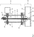
- Fig. 1 shows a semi-automatic solution which is not part of the present invention.
- a device 10 is installed on the rotary kiln shell 33 and executes the work steps for the temperature measurement.
- thermocouple 12 is located in an elongated hollow body 11.
- its measuring tip 13 is either permanently outside of the elongated hollow body 11 or the thermocouple 12 can be moved separately such that its tip 13 is moved in and out of the elongated hollow body 11.
- the thermocouple 12 is preferably protected by a protection pipe 14, leaving the measuring tip 13 exposed to allow for the quick response to temperature changes.
- the tip 13 can be positioned outside of the elongated hollow body 11 by an actuator 25 on top of the elongated hollow body 11.
- the actuator 25 shifts the thermocouple 12 together with the protection pipe 14.
- the elongated hollow body 11 is located in an opening 31 in the refractory lining 37 of the rotary kiln to protect it against wear of the material and high temperatures/ temperature changes.
- the opening 31 is protected by a sleeve 36 so that a possible displacement of the refractory lining 37 does not damage the elongated hollow body 11.
- the sleeve 36 is made from heat resistant steel.
- the installation and de-installation of the elongated hollow body 11 at the rotary kiln shell 33 can be done quickly, e.g. by means of a bayonet fitting. But in normal operation only the thermocouple 12 with the protection pipe 14 has to be changed occasionally.
- spindles 21 are shown which are fixed, parallel to each other, at the ground flange 26 of the device 10 which in turn is mounted on a flanged nozzle on the shell of the rotary kiln 30.
- the spindles are supported by a frame 28, which is not shown in the figure.
- the worm wheels 22 with the spindle nuts are attached at the plate 24 in such a way that they are able to rotate without changing their position relative to the plate 24; they are rotated by the worm 23 which in turn is driven by the drive 20.
- the drive 20 is an electric motor.
- the plate 24, the worm wheels 22, the worm 23 and the drive 20 move up and down the spindles 21, together with the elongated hollow body 11, the thermocouple 12 and the protection pipe 14, when the drive 20 is operated.
- the elongated hollow body 11 preferably made of heat resistant steel, is fixed with a bayonet fitting to the plate 24. This design allows a linear movement of the elongated hollow body 11 with a high force and a self-locking effect.
- the drive 20 moves the plate 24 and the elongated hollow body 11 through the opening 31 into the rotary kiln 30. To prevent thick accretions in front of the opening 31, this will be done in defined temporal intervals.
- the thermocouple 12 with the protection pipe 14 can be shifted forward into the measurement position in the interior 32 of the rotary kiln by means of the actuator 25. In this measurement position the measuring tip 13 of the thermocouple 12 is not surrounded by the elongated hollow body 11 for a quick response temperature measurement
- the quick response temperature measurement is working in an automated way.
- the automatic working procedure can be initialized in the control room. No operating personnel are needed on-site during the measurement.
- Fig. 2 shows a device 10 identical to the one of fig. 1 in a second view.
- Fig. 3 shows a detail of fig. 1 and 2 wherein an additional protection pipe 14 in the elongated hollow body 11 supports the thermocouple 12.
- the protection pipe 14 can be pulled back into the tip of the elongated hollow body 11 together with the thermocouple 12. During the measurement only the measurement tip 13 of the thermocouple 12 is unprotected.
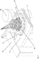
- Fig. 4 discloses a fully-automatic solution for changing the thermocouples 12 together with the protection pipes 14 automatically.
- the principal design of this device 10 is similar to the semi-automatic solution, but the elongated hollow body 11 has a larger diameter and contains a magazine 40, e.g. a drum magazine, loaded with thermocouples 12 and protection pipes 14.
- a magazine 40 e.g. a drum magazine
- the mechanism for the automatic change of thermocouples is arranged on top of the elongated hollow body 11 and consists of a drive motor 43, a magazine drive 42, e.g. a Geneva drive, for the stepwise rotation of the magazine 40, and a mechanism 41, e.g. a cylindrical cam mechanism to convert the rotational movement of the drive motor 43 into an axial movement of the thermocouples 12.
- thermocouples 12 positioned eccentrically in the elongated hollow body, but in the bottom of the elongated hollow body there is only one eccentric hole, through which the selected thermocouple can be shifted into the measuring position.
- the opening 31 in the shell of the rotary kiln 30 and its refractory lining 37 is concentric to the centerline of the elongated hollow body 11.
- thermocouple changing mechanism 41 and 42 positions a thermocouple 12 through the eccentric opening in the bottom of the elongated hollow body 11 into its measuring position in the interior of the rotary kiln.
- the mechanism stops at the next position of the magazine 40. If all thermocouples 12 are defect, the magazine 40 can be changed manually.
- thermocouple In a preferred embodiment of the invention the change of a thermocouple is only affected when the opening 31 is not filled with solid material, i.e. the device 10 is in a high position, e.g. as shown in Fig. 4 .
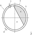
- Fig. 5 depicts a section of a rotary kiln 30 with a thermocouple 12 protruding inside.
- the rotary kiln features a gas phase 35 and is partially filled with solid particles 34.
- the solid particles 34 do not rotate together with the rotary kiln 30, but always remain in the shown position. So during one revolution of the rotary kiln 30 in the direction of rotation 38 the thermocouple 12 is first measuring the temperature of the gas phase and then the temperature of the solid particles.
- Fig. 6 shows schematically a temperature profile during one revolution of the rotary kiln during operation. As it can be seen, sudden temperature changes are measured when the thermocouple is immersed into the solid particles and when it emerges from the solid particles.
- the elongated hollow body can be positioned accordingly by means of the drive 20, and the measurement can start.
- the temperature gradient between temperature from the kiln inside and from the shell temperature can be used for a determination of the accretion thickness.
Landscapes
- Engineering & Computer Science (AREA)
- Mechanical Engineering (AREA)
- General Engineering & Computer Science (AREA)
- Physics & Mathematics (AREA)
- General Physics & Mathematics (AREA)
- Muffle Furnaces And Rotary Kilns (AREA)
- Waste-Gas Treatment And Other Accessory Devices For Furnaces (AREA)
- Drying Of Solid Materials (AREA)
Description
- The invention is directed to a device for measuring the temperature in a rotary kiln through which material passes being heated to elevated temperatures. This invention also covers a rotary kiln equipped with said device and a process for measuring the inside temperature of the rotary kiln in situ.
- Temperature measurements are of particular importance for each process control. Especially for continuous processes, these measurements have to be local and time resolved. For a rotary kiln, a pyroprocessing device used to thermally treat solid materials at high to extremely high temperatures (calcination or direct reduction) in a continuous process, such measurement is particularly challenging.
- Commonly, thermocouples (mostly thermoelectric pyrometers) have been used which were fastened to the kiln shell and which rotate with the kiln. As e.g. disclosed in
DE 1473305 A1 , radiation pyrometers are fixed on the kiln's shell. Further, it is possible that the thermocouples are moved in and out of the rotary kiln's interior manually during operation of the rotary kiln. For a quick response temperature measurement (required for the determination of exact gas and solid material temperatures, dynamic angle of repose and filling degree) a hardly protected thermocouple with a very low live time has to be inserted. - According to
DE1473305 A1 , the procedure of installation and removal of a thermocouple for quick response temperature measurement is manually executed during operation at the rotating kiln. That causes many risks of injuries for the operating personnel due to the rotary movement of the kiln and is therefore no longer acceptable according to current occupational health and safety regulations. - The following work steps have to be done by the operating staff for one measurement while the kiln continues rotating:
- 1. Open the socket (closed with a blind cover)
- 2. Breakthrough of accretions (very critical step)
- 3. Measurement of the accretion thickness (for correct measurement depth)
- 4. Fixing of the bayonet fitting at the protection pipe (including thermocouple) with the clamping flange
- 5. Installation of the protection pipe at the kiln and fixing with the bayonet fitting
- 6. Connection of thermocouple to measuring cable
- 7. Measurement of the temperature
- 8. Separation of thermocouple from measuring cable at the kiln shell
- 9. Removal of protection pipe
- 10. Closing the socket with the blind cover
- The most critical step is the breakthrough of the accretions inside the kiln. They can be very hard and thick, depending on process parameters and the position in the kiln.
- Summing up, the problem during this procedure is to ensure the work safety. The operating personnel have to work at the rotating and hot kiln shell. Hot material and hot gases with high carbon monoxide content can escape from the open socket. These conditions cause a high risk of injuries and health issues Other examples of systems for measuring the temperature in a rotary kiln are known e.g. from
CN105333968 A ,CN105067138 A andCN105115612 A . InCN105333968 A , a drive unit (21) drives an elongated hollow body (4) together with a thermocouple (3) in and out of the kiln. InCN105067138 A , a slotting skewer (3) is inserted into the kiln and goes in and out of the kiln for removing accretions in front of the opening, the rotation of shaft (9) enables a thermocouple (5) to come in front of the opening and the thermocouple (5) is inserted into the kiln for temperature measurement. InCN105115612 A , a slotting skewer (3) is inserted into the kiln and goes in and out of the kiln for removing accretions in front of the opening, a lateral/horizontal translation of the backplate (1) enables a thermocouple (5) to come in front of the opening and the thermocouple (5) is inserted into the kiln for temperature measurement. - Therefore, it is the object underlying the invention to provide a device for an in situ temperature measurement in a rotary kiln with increased safety for the operating personnel.
- This task is solved with a device with the features of
claim 1. - The invention provides a device for measuring the temperature in a rotary kiln through which material passes being heated to elevated temperatures. As the essential part of the invention the device features a drive as well as an elongated hollow body with means to fix a thermocouple. The drive and the elongated hollow body are mounted such that they rotate jointly with the rotary kiln. Further, the drive can move the elongated hollow body together with thermocouple through an opening in and out of the rotary kiln's interior for measuring the temperature inside the rotary kiln during operation.
- As a result, the invention offers the advantage that no manual work has to be done at the kiln during operation, i.e. with the kiln rotating. That increases the work safety since an easy execution of the measurement procedure from the control room is possible.
- Moreover, due to the less preparation work and the simpler measurement execution more measurements per time unit are possible, which leads to a better process control in the rotary kiln. Finally, the automation reduces personnel costs.
- With an automated and driven device regular cleaning intervals of the measuring point can be applied. To achieve this cleaning, the elongated hollow body is moved in and out of the kiln just for breaking the accretion layer before it can lead to problems or blockages.
- In addition, the whole device can be manually removed from the kiln shell and replaced by another device during short periods of interrupted kiln rotation. This makes the maintenance and repair works very easy and comfortable without long stops of the kiln.
- According to the present invention, the elongated hollow body is tubular and/or the thermocouple can be mounted such that its measuring tip protrudes out of the elongated hollow body. The extension of the thermocouple measuring tip out of the elongated hollow body is of particular importance for a quick response temperature measurement in the rotary kiln since it was found that the solid material in the lower part of the rotary kiln and the gas in the upper part of the rotary kiln, the so-called free board above the solid material have different temperatures. Only with a high reaction speed of the temperature measurement the exact solid material and gas temperatures can be detected within one revolution. Additionally the position of the material (dynamic angle of repose and filling degree) can be determined by a sudden change in the temperature profile during one revolution (see
figure 5 ). Such a sudden change cannot be detected if the measuring tip is covered with a protective layer like the protection pipe and/or the elongated hollow body, which is why the measuring tip has to be unshielded or only very weak protected during the measurement. - In this context, the thermocouple is designed according to the present invention such that it can be moved separately from the elongated hollow body in and out of the elongated hollow body. Thereby, the elongated hollow body can be used completely separately, shielding the thermocouple measurement tip inside, to break a hole through the accretions on the inside diameter of the rotary kiln before the measurement itself is done by shifting the measuring tip of the thermocouple through the elongated hollow body by means of a mechanical actuator. In this way the measurement tip is protected from damages.
- For a better breakthrough of the accretions a favorable embodiment of the invention foresees that the elongated hollow body is tapered at the side directed towards the rotary kiln.
- It is also preferred that the elongated hollow body is made of heat resistant steel to ensure thermal and mechanical stability in equal measure.
- Moreover, an additional protection pipe between the elongated hollow body and the thermocouple is foreseen for additional protection and stabilization of the thermocouple.
- Furthermore, it is preferred that the elongated hollow body is mounted such that in the stand-by position it protects the thermocouple against wear caused by the solid material inside the rotary kiln and high temperatures/ temperature changes.
- In another preferred embodiment the drive for the elongated hollow body and the actuator for the thermocouple are designed as electric motors, which can be operated very easily. In a particularly preferred embodiment electrical power is supplied to the cylindrical shell of the rotary kiln by means of slip rings. In many rotary kiln applications those slip rings already exist for other purposes and can, therefore, also be used for the drive of the elongated hollow body and for the actuator of the thermocouple.
- In a particularly practical design the movement of the drive is transmitted to the elongated hollow body and/or the thermocouple by means of at least one, preferably two worm wheels, driven by a worm, and moving up and down on threaded spindles. The use of two parallel spindles has the advantages of a guided movement. Using a worm and worm wheels has the advantage of an additional self-locking effect.
- However, one spindle with an additional guide is also possible. The usage of another gear type, for example a rack with pinion, a coupler mechanism or hydraulic systems is feasible, too.
- As discussed above, it is essential for the required short response time, that thermocouples without any protection against wear and thermal shocks are used. That causes a very low durability and limited life-time of these thermocouples. Therefore, the thermocouples have to be exchanged frequently during operation.
- Two different ways of thermocouple exchange are described:
- a) a semi-automatic solution which is not part of the present invention according to which the rotary kiln has to be stopped for a very short time only and the thermocouple together with its protection pipe is exchanged manually;
- b) a fully-automatic solution as per the present invention according to which the exchange of the thermocouple together with its protection pipe is done by a mechanical drive installed on the kiln shell; the procedure of removal of a damaged thermocouple and installation of a new thermocouple is executed automatically during operation of the rotating kiln.
- In both cases the accretions inside the rotary kiln in front of the thermocouple will be automatically broken by an elongated hollow body without any manual interaction and the thermocouple will be automatically moved between a measuring position and a stand-by position. In both cases, the rotary kiln has to be stopped to manually exchange the elongated hollow body in case of wear or damage. However, as per this invention, the elongated hollow body is fixed with a bayonet fitting for quick manual exchange.
- According to of the fully-automatic solution as per the present invention, a magazine is foreseen to provide at least two, preferably at least six thermocouples. When one thermocouple is damaged, it will be automatically retracted inside the elongated hollow body, the magazine will be rotated by one position and a new thermocouple from the magazine will be inserted into the measurement position. So it is possible to avoid any direct manual interaction of operating personnel with the rotary kiln during operation.
- Preferably, the magazine is manually exchangeable during short stoppages of the rotation of the rotary kiln. So the magazine can be replaced very fast and easy as a whole.
- In a preferred embodiment the magazine is a drum magazine for a failure-free operation. Also a turret magazine is possible.
- Moreover, it is preferred that the magazine is moved by a separate drive to achieve full automation, e.g. a Geneva drive. Out of the reasons discussed above, an electric motor is preferred as a drive motor for the Geneva drive.
- Moreover, the invention covers a rotary kiln, characterized in that at least one device for temperature measurement according to any of
claims 1 to 10 is mounted on the shell of the rotary kiln. - Thereby, the device can be retrofitted to already existing rotary kilns very easily: The semi-automatic solution can be installed at the nozzle for the manual QRT measurements and only a few modifications like the installation of the flange at the kiln shell have to be done. The fully-automatic solution is designed for the nozzles of the sampling ports. For a complete modification of an existing plant more ports are needed at the kiln shell. The initialization of the measuring procedure and other control functions can be done in the control room.
- The shell temperatures are critical for this device. Additional to an insulation layer e.g. made of air chambers between base flange of the device and flange at the shell, a heat shield made of aluminum should be installed between kiln shell and flange, to protect it against thermal radiation. Furthermore a part of the air from the existing air injection fans can be taken to provide cooling air for the device. If no air injection fans exist, a new air fan can be installed to supply ambient cooling air. The fan can be driven by an electric motor also installed on the shell of the rotary kiln. The electric power for the drive can be provided by means of the slip rings also supplying electric power to the device described above.
- The invention covers also a method for temperature measurement in a rotary kiln with the features of
claim 10. - Thereby, a thermocouple protected by an elongated hollow body is moved into the interior of the rotary kiln. The thermocouple can be positioned for measurement through the elongated hollow body by means of an actuator in such a way, that the temperature sensitive tip of the thermocouple protrudes out of the interior (hot) end of the elongated hollow body. The same actuator can also retract the thermocouple back into the elongated hollow body to provide mechanical protection of the temperature sensitive tip of the thermocouple which is also very sensitive to wear and mechanical damage. The latter position of the thermocouple inside the elongated hollow body is called the stand-by position.
- It is of particular importance that the measurement covers one complete revolution of the rotary kiln as a minimum.
- The drawings show schematically:
- Fig. 1
- shows schematically the semi-automatic solution with two spindles and two worm wheels,
- Fig. 2
- shows schematically a second view of the semi-automatic solution with two spindles and two worm wheels,
- Fig. 3
- shows schematically a close up of the thermocouple in the elongated hollow body in the semi-automatic solution,
- Fig. 4
- shows schematically the fully-automatic solution as per the present invention using a drum magazine,
- Fig. 5
- shows schematically a section of a rotary kiln with a thermocouple inside and
- Fig. 6
- shows schematically a temperature profile during one revolution of a rotary kiln during operation.
-
Fig. 1 shows a semi-automatic solution which is not part of the present invention. Therein, adevice 10 is installed on therotary kiln shell 33 and executes the work steps for the temperature measurement. - In detail, a
thermocouple 12 is located in an elongatedhollow body 11. For a high speed of response its measuringtip 13 is either permanently outside of the elongatedhollow body 11 or thethermocouple 12 can be moved separately such that itstip 13 is moved in and out of the elongatedhollow body 11. Thethermocouple 12 is preferably protected by aprotection pipe 14, leaving the measuringtip 13 exposed to allow for the quick response to temperature changes. - For the latter case, it is preferred that the
tip 13 can be positioned outside of the elongatedhollow body 11 by anactuator 25 on top of the elongatedhollow body 11. Theactuator 25 shifts thethermocouple 12 together with theprotection pipe 14. In the stand-by position the elongatedhollow body 11 is located in anopening 31 in therefractory lining 37 of the rotary kiln to protect it against wear of the material and high temperatures/ temperature changes. Theopening 31 is protected by asleeve 36 so that a possible displacement of therefractory lining 37 does not damage the elongatedhollow body 11. Typically, thesleeve 36 is made from heat resistant steel. - Preferably, the installation and de-installation of the elongated
hollow body 11 at therotary kiln shell 33 can be done quickly, e.g. by means of a bayonet fitting. But in normal operation only thethermocouple 12 with theprotection pipe 14 has to be changed occasionally. - Further, two
spindles 21 are shown which are fixed, parallel to each other, at theground flange 26 of thedevice 10 which in turn is mounted on a flanged nozzle on the shell of therotary kiln 30. The spindles are supported by aframe 28, which is not shown in the figure. Theworm wheels 22 with the spindle nuts are attached at theplate 24 in such a way that they are able to rotate without changing their position relative to theplate 24; they are rotated by theworm 23 which in turn is driven by thedrive 20. Preferably, thedrive 20 is an electric motor. Theplate 24, theworm wheels 22, theworm 23 and thedrive 20 move up and down thespindles 21, together with the elongatedhollow body 11, thethermocouple 12 and theprotection pipe 14, when thedrive 20 is operated. - The elongated
hollow body 11, preferably made of heat resistant steel, is fixed with a bayonet fitting to theplate 24. This design allows a linear movement of the elongatedhollow body 11 with a high force and a self-locking effect. - For the breakthrough of accretions the
drive 20 moves theplate 24 and the elongatedhollow body 11 through theopening 31 into therotary kiln 30. To prevent thick accretions in front of theopening 31, this will be done in defined temporal intervals. Once theopening 31 is free of accretions, thethermocouple 12 with theprotection pipe 14 can be shifted forward into the measurement position in theinterior 32 of the rotary kiln by means of theactuator 25. In this measurement position the measuringtip 13 of thethermocouple 12 is not surrounded by the elongatedhollow body 11 for a quick response temperature measurement - According to both the semi-automatic and the fully-automatic solutions the quick response temperature measurement is working in an automated way. When a temperature measurement is required, the automatic working procedure can be initialized in the control room. No operating personnel are needed on-site during the measurement.
-
Fig. 2 shows adevice 10 identical to the one offig. 1 in a second view. -
Fig. 3 shows a detail offig. 1 and2 wherein anadditional protection pipe 14 in the elongatedhollow body 11 supports thethermocouple 12. To achieve the stand-by position of thethermocouple 12, theprotection pipe 14 can be pulled back into the tip of the elongatedhollow body 11 together with thethermocouple 12. During the measurement only themeasurement tip 13 of thethermocouple 12 is unprotected. -
Fig. 4 discloses a fully-automatic solution for changing thethermocouples 12 together with theprotection pipes 14 automatically. The principal design of thisdevice 10 is similar to the semi-automatic solution, but the elongatedhollow body 11 has a larger diameter and contains amagazine 40, e.g. a drum magazine, loaded withthermocouples 12 andprotection pipes 14. - The mechanism for the automatic change of thermocouples is arranged on top of the elongated
hollow body 11 and consists of adrive motor 43, amagazine drive 42, e.g. a Geneva drive, for the stepwise rotation of themagazine 40, and amechanism 41, e.g. a cylindrical cam mechanism to convert the rotational movement of thedrive motor 43 into an axial movement of thethermocouples 12. - In the fully-automatic solution a number of
thermocouples 12 positioned eccentrically in the elongated hollow body, but in the bottom of the elongated hollow body there is only one eccentric hole, through which the selected thermocouple can be shifted into the measuring position. However, theopening 31 in the shell of therotary kiln 30 and itsrefractory lining 37 is concentric to the centerline of the elongatedhollow body 11. - In the stand-by position of the elongated hollow body 11 a round steel bar seals the eccentric opening in the bottom of the elongated
hollow body 11. To start a measurement, the elongatedhollow body 11 is first moved by means of thedrive 20 into the interior 32 of therotary kiln 30 to break any accretions and then thethermocouple changing mechanism thermocouple 12 through the eccentric opening in the bottom of the elongatedhollow body 11 into its measuring position in the interior of the rotary kiln. In case of adefect thermocouple 12, the mechanism stops at the next position of themagazine 40. If allthermocouples 12 are defect, themagazine 40 can be changed manually. - In a preferred embodiment of the invention the change of a thermocouple is only affected when the
opening 31 is not filled with solid material, i.e. thedevice 10 is in a high position, e.g. as shown inFig. 4 . -
Fig. 5 depicts a section of arotary kiln 30 with athermocouple 12 protruding inside. The rotary kiln features agas phase 35 and is partially filled withsolid particles 34. Thesolid particles 34 do not rotate together with therotary kiln 30, but always remain in the shown position. So during one revolution of therotary kiln 30 in the direction ofrotation 38 thethermocouple 12 is first measuring the temperature of the gas phase and then the temperature of the solid particles. -
Fig. 6 shows schematically a temperature profile during one revolution of the rotary kiln during operation. As it can be seen, sudden temperature changes are measured when the thermocouple is immersed into the solid particles and when it emerges from the solid particles. - To determine the thickness of the accretion layer in the kiln, a change in the temperature profile during movement of the elongated
hollow body 11 into the kiln will be used. Therefore, the accretions in front of theopening 31 are broken and theactuator 25 has positioned the thermocouple in measurement position. The temperature change during moving in of the elongated hollow body with the measuringtip 13 in measuring position is caused by a higher heat transfer outside the accretion layer because of the gas velocity and the thermal radiation in the kiln. With the information of the accretion thickness, the elongated hollow body can be positioned accordingly by means of thedrive 20, and the measurement can start. - Alternatively the temperature gradient between temperature from the kiln inside and from the shell temperature can be used for a determination of the accretion thickness.
-
- 10
- device
- 11
- elongated hollow body
- 12
- thermocouple
- 13
- thermocouple measurement tip
- 14
- protection pipe
- 20
- drive
- 21
- spindle
- 22
- worm wheel
- 23
- worm
- 24
- plate
- 25
- actuator
- 26
- ground flange
- 27
- bayonet fitting
- 28
- frame
- 30
- rotary kiln
- 31
- opening
- 32
- rotary kiln interior
- 33
- rotary kiln shell
- 34
- solid particles
- 35
- gas phase
- 36
- sleeve
- 37
- refractory lining
- 38
- direction of rotation
- 40
- magazine
- 41
- cylindrical cam mechanism
- 42
- Geneva drive
- 43
- drive motor
Claims (11)
- A device (10) for measuring the temperature in a rotary kiln (30) through which solid material passes being heated to elevated temperatures, comprising a drive (20) as well as an elongated hollow body (11) with means to fix a thermocouple (12), whereby the drive (20) and the elongated hollow body (11) are mounted such that they rotate jointly with the rotary kiln (30) and that the drive (20) can move the elongated hollow body (11) together with thermocouple (12) through an opening (31) in and out of the rotary kiln interior (32) for measuring the temperature inside the rotary kiln (30) during operation, wherein
the elongated hollow body (11) is tubular and the thermocouple (12) can be shifted by an actuator (25) such that its temperature sensitive tip (13) protrudes out of the elongated hollow body (11) characterized in that the thermocouple (12) is designed such that it can be moved separately from the elongated hollow body (11) in and out for better protection of the thermocouple (12);
a magazine (40) is foreseen to provide at least two thermocouples (12) and/or elongated hollow bodies (11). - The device (10) according to claim 1, characterized in that the elongated hollow body (11) is tapered at the side directed to the rotary kiln (30).
- The device (10) according to one any of the preceding claims, characterized in that the drive (20) is an electric motor.
- The device (10) according to one any of the preceding claims, characterized in that a protection pipe (14) is foreseen between the elongated hollow body (11) and the thermocouple (12).
- The device (10) according to any of the preceding claims, characterized in that the movement of the drive (20) is transmitted to the elongated hollow body (11) and/or the thermocouple (12) by means of at least one worm wheel (22).
- The device (10) according to claim 1, characterized in that the magazine (40) is exchangeable.
- The device (10) according to claim 1 or 6, characterized in that the magazine (40) is a drum magazine.
- The device (10) according to any of claims 1, 6 or 7, characterized in that the magazine (40) is rotated by a Geneva drive (42).
- A rotary kiln, characterized in that at least one device (10) for temperature measurement according to any of claims 1 to 8 is mounted of the rotary kiln (30).
- A method for temperature measurement in a rotary kiln, characterized in that temperature measured with a device according to any of claims 1 to 8.
- A method according to claim 10, characterized in that the actuator (25) is controlled such that a temperature measure has a duration of minimal one revolution of the rotary kiln (30).
Priority Applications (1)
| Application Number | Priority Date | Filing Date | Title |
|---|---|---|---|
| RS20210744A RS62001B1 (en) | 2017-08-31 | 2018-07-26 | Automatic quick response temperature measurement for rotary kilns |
Applications Claiming Priority (2)
| Application Number | Priority Date | Filing Date | Title |
|---|---|---|---|
| DE102017119989 | 2017-08-31 | ||
| PCT/EP2018/070286 WO2019042668A1 (en) | 2017-08-31 | 2018-07-26 | Automatic quick response temperature measurement for rotary kilns |
Publications (3)
| Publication Number | Publication Date |
|---|---|
| EP3676552A1 EP3676552A1 (en) | 2020-07-08 |
| EP3676552B1 true EP3676552B1 (en) | 2021-03-17 |
| EP3676552B8 EP3676552B8 (en) | 2021-04-21 |
Family
ID=63047363
Family Applications (1)
| Application Number | Title | Priority Date | Filing Date |
|---|---|---|---|
| EP18746911.9A Active EP3676552B8 (en) | 2017-08-31 | 2018-07-26 | Automatic quick response temperature measurement for rotary kilns |
Country Status (10)
| Country | Link |
|---|---|
| US (1) | US10890379B2 (en) |
| EP (1) | EP3676552B8 (en) |
| CN (1) | CN111133268A (en) |
| AU (1) | AU2018326133B2 (en) |
| ES (1) | ES2880223T3 (en) |
| HU (1) | HUE054591T2 (en) |
| PT (1) | PT3676552T (en) |
| RS (1) | RS62001B1 (en) |
| WO (1) | WO2019042668A1 (en) |
| ZA (1) | ZA202001509B (en) |
Families Citing this family (3)
| Publication number | Priority date | Publication date | Assignee | Title |
|---|---|---|---|---|
| WO2021260252A1 (en) | 2020-06-24 | 2021-12-30 | Metso Outotec Finland Oy | Device for measuring temperature in a rotary kiln and thermocouple unit |
| CN116499274B (en) * | 2023-06-27 | 2023-08-25 | 四川领先微晶玻璃有限公司 | Temperature measurement system used in industrial sintering furnace |
| CN118706278B (en) * | 2024-08-30 | 2024-11-05 | 山东京阳科技股份有限公司 | A coking tower temperature measuring device |
Family Cites Families (7)
| Publication number | Priority date | Publication date | Assignee | Title |
|---|---|---|---|---|
| DE1473305A1 (en) | 1964-06-05 | 1969-04-10 | Polysius Gmbh | Device for temperature measurement in a rotary kiln |
| CN2903945Y (en) * | 2006-03-10 | 2007-05-23 | 首钢总公司 | Thermocouple cleaner |
| DE102007061477A1 (en) * | 2007-12-20 | 2009-07-02 | Man Dwe Gmbh | Tube reactor |
| CN104931147B (en) * | 2015-05-08 | 2018-02-02 | 中冶长天国际工程有限责任公司 | A kind of motor-driven rotary kiln direct temperature measurement device |
| CN105115612B (en) * | 2015-09-24 | 2017-09-12 | 中冶长天国际工程有限责任公司 | A kind of kiln temperature detection means |
| CN105333968B (en) * | 2015-09-24 | 2018-11-30 | 中冶长天国际工程有限责任公司 | A kind of kiln temperature detection device |
| CN105067138B (en) * | 2015-09-24 | 2017-09-12 | 中冶长天国际工程有限责任公司 | A kind of kiln temperature detection means |
-
2018
- 2018-07-26 HU HUE18746911A patent/HUE054591T2/en unknown
- 2018-07-26 PT PT187469119T patent/PT3676552T/en unknown
- 2018-07-26 CN CN201880055656.XA patent/CN111133268A/en active Pending
- 2018-07-26 WO PCT/EP2018/070286 patent/WO2019042668A1/en not_active Ceased
- 2018-07-26 EP EP18746911.9A patent/EP3676552B8/en active Active
- 2018-07-26 RS RS20210744A patent/RS62001B1/en unknown
- 2018-07-26 AU AU2018326133A patent/AU2018326133B2/en not_active Ceased
- 2018-07-26 ES ES18746911T patent/ES2880223T3/en active Active
-
2020
- 2020-02-24 US US16/798,579 patent/US10890379B2/en not_active Expired - Fee Related
- 2020-03-10 ZA ZA2020/01509A patent/ZA202001509B/en unknown
Non-Patent Citations (1)
| Title |
|---|
| None * |
Also Published As
| Publication number | Publication date |
|---|---|
| AU2018326133B2 (en) | 2021-03-25 |
| ZA202001509B (en) | 2021-04-28 |
| US20200191483A1 (en) | 2020-06-18 |
| RS62001B1 (en) | 2021-07-30 |
| PT3676552T (en) | 2021-06-22 |
| WO2019042668A1 (en) | 2019-03-07 |
| EP3676552A1 (en) | 2020-07-08 |
| HUE054591T2 (en) | 2021-09-28 |
| ES2880223T3 (en) | 2021-11-24 |
| CN111133268A (en) | 2020-05-08 |
| US10890379B2 (en) | 2021-01-12 |
| AU2018326133A1 (en) | 2020-04-02 |
| EP3676552B8 (en) | 2021-04-21 |
Similar Documents
| Publication | Publication Date | Title |
|---|---|---|
| US10890379B2 (en) | Automatic quick response temperature measurement for rotary kilns | |
| EP0039212B1 (en) | Apparatus for repair of refractory linings | |
| US3983756A (en) | Probe apparatus for a high pressure chamber | |
| JP2008180451A (en) | External heating type rotary kiln and its operating method | |
| JP4700730B2 (en) | Apparatus for continuous temperature measurement of molten steel in tundish using optical fiber and infrared pyrometer | |
| US20210318069A1 (en) | Device for maintaining a tap hole of an electric arc furnace | |
| CA3002498C (en) | Slide closure on the spout of a metallurgical vessel | |
| CN105067138B (en) | A kind of kiln temperature detection means | |
| CN105333968B (en) | A kind of kiln temperature detection device | |
| CN102334003A (en) | Oxygen lance cooled by protective gas | |
| JP2023015287A (en) | METHOD AND APPARATUS FOR DETECTING DIMENSIONS IN A METALLOGURICAL VESSEL OUTLET | |
| US4075035A (en) | Temperature detecting device for a furnace | |
| US20160282048A1 (en) | Metallurgical furnace probe with ejecting cartridge sensor | |
| KR20200019885A (en) | Kalandria tube insert removal and removal tools and methods | |
| CN108168708A (en) | A kind of steel-making tundish temperature tube, temperature-measuring gun and thermometric robot and its temp measuring method | |
| BR112020010102A2 (en) | mobile hanging machine in translation | |
| CA2973136A1 (en) | Method and device for repairing a refractory shell of a metallurgical vessel | |
| CN211904445U (en) | Temperature measuring device in heat treatment heating furnace | |
| US6034345A (en) | Apparatus for repairing high temperature process vessels | |
| EP0280349B1 (en) | Sub-lance installation for carrying out measurements and/or taking samples in a metallurgical furnace | |
| CN113421679B (en) | Radioactive Waste Treatment System | |
| CN207294821U (en) | Deashing imaging device in State of Blast Furnace | |
| CN206916170U (en) | Iron notch drill | |
| KR101786254B1 (en) | Apparatus for monitoring molten metal in tundish | |
| CN204740075U (en) | A plug-in temperature measuring element removal device |
Legal Events
| Date | Code | Title | Description |
|---|---|---|---|
| STAA | Information on the status of an ep patent application or granted ep patent |
Free format text: STATUS: UNKNOWN |
|
| STAA | Information on the status of an ep patent application or granted ep patent |
Free format text: STATUS: THE INTERNATIONAL PUBLICATION HAS BEEN MADE |
|
| PUAI | Public reference made under article 153(3) epc to a published international application that has entered the european phase |
Free format text: ORIGINAL CODE: 0009012 |
|
| STAA | Information on the status of an ep patent application or granted ep patent |
Free format text: STATUS: REQUEST FOR EXAMINATION WAS MADE |
|
| 17P | Request for examination filed |
Effective date: 20200225 |
|
| AK | Designated contracting states |
Kind code of ref document: A1 Designated state(s): AL AT BE BG CH CY CZ DE DK EE ES FI FR GB GR HR HU IE IS IT LI LT LU LV MC MK MT NL NO PL PT RO RS SE SI SK SM TR |
|
| AX | Request for extension of the european patent |
Extension state: BA ME |
|
| RIC1 | Information provided on ipc code assigned before grant |
Ipc: F27D 19/00 20060101ALI20200831BHEP Ipc: G01K 13/08 20060101ALI20200831BHEP Ipc: F27D 21/00 20060101ALI20200831BHEP Ipc: G01K 1/14 20060101ALI20200831BHEP Ipc: F27B 7/42 20060101AFI20200831BHEP |
|
| GRAP | Despatch of communication of intention to grant a patent |
Free format text: ORIGINAL CODE: EPIDOSNIGR1 |
|
| STAA | Information on the status of an ep patent application or granted ep patent |
Free format text: STATUS: GRANT OF PATENT IS INTENDED |
|
| INTG | Intention to grant announced |
Effective date: 20201014 |
|
| DAV | Request for validation of the european patent (deleted) | ||
| DAX | Request for extension of the european patent (deleted) | ||
| GRAS | Grant fee paid |
Free format text: ORIGINAL CODE: EPIDOSNIGR3 |
|
| GRAA | (expected) grant |
Free format text: ORIGINAL CODE: 0009210 |
|
| STAA | Information on the status of an ep patent application or granted ep patent |
Free format text: STATUS: THE PATENT HAS BEEN GRANTED |
|
| REG | Reference to a national code |
Ref country code: DE Ref legal event code: R081 Ref document number: 602018014137 Country of ref document: DE Owner name: METSO OUTOTEC FINLAND OY, FI Free format text: FORMER OWNER: OUTOTEC (FINLAND) OY, ESPOO, FI |
|
| AK | Designated contracting states |
Kind code of ref document: B1 Designated state(s): AL AT BE BG CH CY CZ DE DK EE ES FI FR GB GR HR HU IE IS IT LI LT LU LV MC MK MT NL NO PL PT RO RS SE SI SK SM TR |
|
| REG | Reference to a national code |
Ref country code: GB Ref legal event code: FG4D |
|
| REG | Reference to a national code |
Ref country code: CH Ref legal event code: PK Free format text: BERICHTIGUNG B8 Ref country code: CH Ref legal event code: EP |
|
| RAP2 | Party data changed (patent owner data changed or rights of a patent transferred) |
Owner name: METSO OUTOTEC FINLAND OY |
|
| REG | Reference to a national code |
Ref country code: DE Ref legal event code: R096 Ref document number: 602018014137 Country of ref document: DE |
|
| REG | Reference to a national code |
Ref country code: IE Ref legal event code: FG4D |
|
| REG | Reference to a national code |
Ref country code: AT Ref legal event code: REF Ref document number: 1372627 Country of ref document: AT Kind code of ref document: T Effective date: 20210415 |
|
| REG | Reference to a national code |
Ref country code: FI Ref legal event code: FGE |
|
| REG | Reference to a national code |
Ref country code: PT Ref legal event code: SC4A Ref document number: 3676552 Country of ref document: PT Date of ref document: 20210622 Kind code of ref document: T Free format text: AVAILABILITY OF NATIONAL TRANSLATION Effective date: 20210616 |
|
| REG | Reference to a national code |
Ref country code: SE Ref legal event code: TRGR |
|
| REG | Reference to a national code |
Ref country code: LT Ref legal event code: MG9D |
|
| PG25 | Lapsed in a contracting state [announced via postgrant information from national office to epo] |
Ref country code: BG Free format text: LAPSE BECAUSE OF FAILURE TO SUBMIT A TRANSLATION OF THE DESCRIPTION OR TO PAY THE FEE WITHIN THE PRESCRIBED TIME-LIMIT Effective date: 20210617 Ref country code: HR Free format text: LAPSE BECAUSE OF FAILURE TO SUBMIT A TRANSLATION OF THE DESCRIPTION OR TO PAY THE FEE WITHIN THE PRESCRIBED TIME-LIMIT Effective date: 20210317 Ref country code: GR Free format text: LAPSE BECAUSE OF FAILURE TO SUBMIT A TRANSLATION OF THE DESCRIPTION OR TO PAY THE FEE WITHIN THE PRESCRIBED TIME-LIMIT Effective date: 20210618 Ref country code: NO Free format text: LAPSE BECAUSE OF FAILURE TO SUBMIT A TRANSLATION OF THE DESCRIPTION OR TO PAY THE FEE WITHIN THE PRESCRIBED TIME-LIMIT Effective date: 20210617 |
|
| REG | Reference to a national code |
Ref country code: AT Ref legal event code: MK05 Ref document number: 1372627 Country of ref document: AT Kind code of ref document: T Effective date: 20210317 |
|
| REG | Reference to a national code |
Ref country code: NL Ref legal event code: MP Effective date: 20210317 |
|
| PG25 | Lapsed in a contracting state [announced via postgrant information from national office to epo] |
Ref country code: LV Free format text: LAPSE BECAUSE OF FAILURE TO SUBMIT A TRANSLATION OF THE DESCRIPTION OR TO PAY THE FEE WITHIN THE PRESCRIBED TIME-LIMIT Effective date: 20210317 |
|
| REG | Reference to a national code |
Ref country code: HU Ref legal event code: AG4A Ref document number: E054591 Country of ref document: HU |
|
| PG25 | Lapsed in a contracting state [announced via postgrant information from national office to epo] |
Ref country code: NL Free format text: LAPSE BECAUSE OF FAILURE TO SUBMIT A TRANSLATION OF THE DESCRIPTION OR TO PAY THE FEE WITHIN THE PRESCRIBED TIME-LIMIT Effective date: 20210317 |
|
| PG25 | Lapsed in a contracting state [announced via postgrant information from national office to epo] |
Ref country code: SM Free format text: LAPSE BECAUSE OF FAILURE TO SUBMIT A TRANSLATION OF THE DESCRIPTION OR TO PAY THE FEE WITHIN THE PRESCRIBED TIME-LIMIT Effective date: 20210317 Ref country code: EE Free format text: LAPSE BECAUSE OF FAILURE TO SUBMIT A TRANSLATION OF THE DESCRIPTION OR TO PAY THE FEE WITHIN THE PRESCRIBED TIME-LIMIT Effective date: 20210317 Ref country code: LT Free format text: LAPSE BECAUSE OF FAILURE TO SUBMIT A TRANSLATION OF THE DESCRIPTION OR TO PAY THE FEE WITHIN THE PRESCRIBED TIME-LIMIT Effective date: 20210317 Ref country code: AT Free format text: LAPSE BECAUSE OF FAILURE TO SUBMIT A TRANSLATION OF THE DESCRIPTION OR TO PAY THE FEE WITHIN THE PRESCRIBED TIME-LIMIT Effective date: 20210317 |
|
| PGFP | Annual fee paid to national office [announced via postgrant information from national office to epo] |
Ref country code: FI Payment date: 20210722 Year of fee payment: 4 Ref country code: CZ Payment date: 20210726 Year of fee payment: 4 |
|
| REG | Reference to a national code |
Ref country code: ES Ref legal event code: FG2A Ref document number: 2880223 Country of ref document: ES Kind code of ref document: T3 Effective date: 20211124 |
|
| PG25 | Lapsed in a contracting state [announced via postgrant information from national office to epo] |
Ref country code: PL Free format text: LAPSE BECAUSE OF FAILURE TO SUBMIT A TRANSLATION OF THE DESCRIPTION OR TO PAY THE FEE WITHIN THE PRESCRIBED TIME-LIMIT Effective date: 20210317 Ref country code: SK Free format text: LAPSE BECAUSE OF FAILURE TO SUBMIT A TRANSLATION OF THE DESCRIPTION OR TO PAY THE FEE WITHIN THE PRESCRIBED TIME-LIMIT Effective date: 20210317 Ref country code: RO Free format text: LAPSE BECAUSE OF FAILURE TO SUBMIT A TRANSLATION OF THE DESCRIPTION OR TO PAY THE FEE WITHIN THE PRESCRIBED TIME-LIMIT Effective date: 20210317 Ref country code: IS Free format text: LAPSE BECAUSE OF FAILURE TO SUBMIT A TRANSLATION OF THE DESCRIPTION OR TO PAY THE FEE WITHIN THE PRESCRIBED TIME-LIMIT Effective date: 20210717 |
|
| PGFP | Annual fee paid to national office [announced via postgrant information from national office to epo] |
Ref country code: RS Payment date: 20210722 Year of fee payment: 4 Ref country code: TR Payment date: 20210716 Year of fee payment: 4 Ref country code: SE Payment date: 20210721 Year of fee payment: 4 Ref country code: ES Payment date: 20210928 Year of fee payment: 4 Ref country code: DE Payment date: 20210721 Year of fee payment: 4 Ref country code: HU Payment date: 20210802 Year of fee payment: 4 |
|
| REG | Reference to a national code |
Ref country code: DE Ref legal event code: R097 Ref document number: 602018014137 Country of ref document: DE |
|
| PGFP | Annual fee paid to national office [announced via postgrant information from national office to epo] |
Ref country code: PT Payment date: 20210715 Year of fee payment: 4 |
|
| PLBE | No opposition filed within time limit |
Free format text: ORIGINAL CODE: 0009261 |
|
| STAA | Information on the status of an ep patent application or granted ep patent |
Free format text: STATUS: NO OPPOSITION FILED WITHIN TIME LIMIT |
|
| PG25 | Lapsed in a contracting state [announced via postgrant information from national office to epo] |
Ref country code: DK Free format text: LAPSE BECAUSE OF FAILURE TO SUBMIT A TRANSLATION OF THE DESCRIPTION OR TO PAY THE FEE WITHIN THE PRESCRIBED TIME-LIMIT Effective date: 20210317 Ref country code: AL Free format text: LAPSE BECAUSE OF FAILURE TO SUBMIT A TRANSLATION OF THE DESCRIPTION OR TO PAY THE FEE WITHIN THE PRESCRIBED TIME-LIMIT Effective date: 20210317 |
|
| 26N | No opposition filed |
Effective date: 20211220 |
|
| REG | Reference to a national code |
Ref country code: CH Ref legal event code: PL |
|
| PG25 | Lapsed in a contracting state [announced via postgrant information from national office to epo] |
Ref country code: MC Free format text: LAPSE BECAUSE OF FAILURE TO SUBMIT A TRANSLATION OF THE DESCRIPTION OR TO PAY THE FEE WITHIN THE PRESCRIBED TIME-LIMIT Effective date: 20210317 |
|
| REG | Reference to a national code |
Ref country code: BE Ref legal event code: MM Effective date: 20210731 |
|
| PG25 | Lapsed in a contracting state [announced via postgrant information from national office to epo] |
Ref country code: LI Free format text: LAPSE BECAUSE OF NON-PAYMENT OF DUE FEES Effective date: 20210731 Ref country code: IT Free format text: LAPSE BECAUSE OF FAILURE TO SUBMIT A TRANSLATION OF THE DESCRIPTION OR TO PAY THE FEE WITHIN THE PRESCRIBED TIME-LIMIT Effective date: 20210317 Ref country code: CH Free format text: LAPSE BECAUSE OF NON-PAYMENT OF DUE FEES Effective date: 20210731 |
|
| PG25 | Lapsed in a contracting state [announced via postgrant information from national office to epo] |
Ref country code: IS Free format text: LAPSE BECAUSE OF FAILURE TO SUBMIT A TRANSLATION OF THE DESCRIPTION OR TO PAY THE FEE WITHIN THE PRESCRIBED TIME-LIMIT Effective date: 20210717 Ref country code: LU Free format text: LAPSE BECAUSE OF NON-PAYMENT OF DUE FEES Effective date: 20210726 Ref country code: FR Free format text: LAPSE BECAUSE OF NON-PAYMENT OF DUE FEES Effective date: 20210731 |
|
| PG25 | Lapsed in a contracting state [announced via postgrant information from national office to epo] |
Ref country code: IE Free format text: LAPSE BECAUSE OF NON-PAYMENT OF DUE FEES Effective date: 20210726 Ref country code: BE Free format text: LAPSE BECAUSE OF NON-PAYMENT OF DUE FEES Effective date: 20210731 |
|
| REG | Reference to a national code |
Ref country code: DE Ref legal event code: R119 Ref document number: 602018014137 Country of ref document: DE |
|
| REG | Reference to a national code |
Ref country code: SE Ref legal event code: EUG |
|
| GBPC | Gb: european patent ceased through non-payment of renewal fee |
Effective date: 20220726 |
|
| PG25 | Lapsed in a contracting state [announced via postgrant information from national office to epo] |
Ref country code: SE Free format text: LAPSE BECAUSE OF NON-PAYMENT OF DUE FEES Effective date: 20220727 Ref country code: PT Free format text: LAPSE BECAUSE OF NON-PAYMENT OF DUE FEES Effective date: 20230126 Ref country code: FI Free format text: LAPSE BECAUSE OF NON-PAYMENT OF DUE FEES Effective date: 20220726 Ref country code: CZ Free format text: LAPSE BECAUSE OF NON-PAYMENT OF DUE FEES Effective date: 20220726 |
|
| PG25 | Lapsed in a contracting state [announced via postgrant information from national office to epo] |
Ref country code: RS Free format text: LAPSE BECAUSE OF NON-PAYMENT OF DUE FEES Effective date: 20220726 Ref country code: HU Free format text: LAPSE BECAUSE OF NON-PAYMENT OF DUE FEES Effective date: 20220727 Ref country code: GB Free format text: LAPSE BECAUSE OF NON-PAYMENT OF DUE FEES Effective date: 20220726 Ref country code: DE Free format text: LAPSE BECAUSE OF NON-PAYMENT OF DUE FEES Effective date: 20230201 |
|
| PG25 | Lapsed in a contracting state [announced via postgrant information from national office to epo] |
Ref country code: CY Free format text: LAPSE BECAUSE OF FAILURE TO SUBMIT A TRANSLATION OF THE DESCRIPTION OR TO PAY THE FEE WITHIN THE PRESCRIBED TIME-LIMIT Effective date: 20210317 |
|
| REG | Reference to a national code |
Ref country code: ES Ref legal event code: FD2A Effective date: 20230825 |
|
| PG25 | Lapsed in a contracting state [announced via postgrant information from national office to epo] |
Ref country code: SI Free format text: LAPSE BECAUSE OF FAILURE TO SUBMIT A TRANSLATION OF THE DESCRIPTION OR TO PAY THE FEE WITHIN THE PRESCRIBED TIME-LIMIT Effective date: 20210317 |
|
| PG25 | Lapsed in a contracting state [announced via postgrant information from national office to epo] |
Ref country code: ES Free format text: LAPSE BECAUSE OF NON-PAYMENT OF DUE FEES Effective date: 20220727 |
|
| PG25 | Lapsed in a contracting state [announced via postgrant information from national office to epo] |
Ref country code: MK Free format text: LAPSE BECAUSE OF FAILURE TO SUBMIT A TRANSLATION OF THE DESCRIPTION OR TO PAY THE FEE WITHIN THE PRESCRIBED TIME-LIMIT Effective date: 20210317 |
|
| PG25 | Lapsed in a contracting state [announced via postgrant information from national office to epo] |
Ref country code: MT Free format text: LAPSE BECAUSE OF FAILURE TO SUBMIT A TRANSLATION OF THE DESCRIPTION OR TO PAY THE FEE WITHIN THE PRESCRIBED TIME-LIMIT Effective date: 20210317 |