EP3676223B1 - Efficient procedure to process solid organic waste - Google Patents
Efficient procedure to process solid organic waste Download PDFInfo
- Publication number
- EP3676223B1 EP3676223B1 EP18854431.6A EP18854431A EP3676223B1 EP 3676223 B1 EP3676223 B1 EP 3676223B1 EP 18854431 A EP18854431 A EP 18854431A EP 3676223 B1 EP3676223 B1 EP 3676223B1
- Authority
- EP
- European Patent Office
- Prior art keywords
- container
- organic waste
- solid organic
- humidity
- inert material
- Prior art date
- Legal status (The legal status is an assumption and is not a legal conclusion. Google has not performed a legal analysis and makes no representation as to the accuracy of the status listed.)
- Active
Links
Images


Classifications
-
- B—PERFORMING OPERATIONS; TRANSPORTING
- B01—PHYSICAL OR CHEMICAL PROCESSES OR APPARATUS IN GENERAL
- B01D—SEPARATION
- B01D53/00—Separation of gases or vapours; Recovering vapours of volatile solvents from gases; Chemical or biological purification of waste gases, e.g. engine exhaust gases, smoke, fumes, flue gases, aerosols
- B01D53/34—Chemical or biological purification of waste gases
- B01D53/74—General processes for purification of waste gases; Apparatus or devices specially adapted therefor
- B01D53/84—Biological processes
-
- B—PERFORMING OPERATIONS; TRANSPORTING
- B09—DISPOSAL OF SOLID WASTE; RECLAMATION OF CONTAMINATED SOIL
- B09B—DISPOSAL OF SOLID WASTE NOT OTHERWISE PROVIDED FOR
- B09B3/00—Destroying solid waste or transforming solid waste into something useful or harmless
- B09B3/40—Destroying solid waste or transforming solid waste into something useful or harmless involving thermal treatment, e.g. evaporation
-
- C—CHEMISTRY; METALLURGY
- C10—PETROLEUM, GAS OR COKE INDUSTRIES; TECHNICAL GASES CONTAINING CARBON MONOXIDE; FUELS; LUBRICANTS; PEAT
- C10B—DESTRUCTIVE DISTILLATION OF CARBONACEOUS MATERIALS FOR PRODUCTION OF GAS, COKE, TAR, OR SIMILAR MATERIALS
- C10B27/00—Arrangements for withdrawal of the distillation gases
- C10B27/06—Conduit details, e.g. valves
-
- C—CHEMISTRY; METALLURGY
- C10—PETROLEUM, GAS OR COKE INDUSTRIES; TECHNICAL GASES CONTAINING CARBON MONOXIDE; FUELS; LUBRICANTS; PEAT
- C10B—DESTRUCTIVE DISTILLATION OF CARBONACEOUS MATERIALS FOR PRODUCTION OF GAS, COKE, TAR, OR SIMILAR MATERIALS
- C10B41/00—Safety devices, e.g. signalling or controlling devices for use in the discharge of coke
-
- C—CHEMISTRY; METALLURGY
- C10—PETROLEUM, GAS OR COKE INDUSTRIES; TECHNICAL GASES CONTAINING CARBON MONOXIDE; FUELS; LUBRICANTS; PEAT
- C10B—DESTRUCTIVE DISTILLATION OF CARBONACEOUS MATERIALS FOR PRODUCTION OF GAS, COKE, TAR, OR SIMILAR MATERIALS
- C10B53/00—Destructive distillation, specially adapted for particular solid raw materials or solid raw materials in special form
-
- C—CHEMISTRY; METALLURGY
- C10—PETROLEUM, GAS OR COKE INDUSTRIES; TECHNICAL GASES CONTAINING CARBON MONOXIDE; FUELS; LUBRICANTS; PEAT
- C10B—DESTRUCTIVE DISTILLATION OF CARBONACEOUS MATERIALS FOR PRODUCTION OF GAS, COKE, TAR, OR SIMILAR MATERIALS
- C10B53/00—Destructive distillation, specially adapted for particular solid raw materials or solid raw materials in special form
- C10B53/02—Destructive distillation, specially adapted for particular solid raw materials or solid raw materials in special form of cellulose-containing material
-
- C—CHEMISTRY; METALLURGY
- C10—PETROLEUM, GAS OR COKE INDUSTRIES; TECHNICAL GASES CONTAINING CARBON MONOXIDE; FUELS; LUBRICANTS; PEAT
- C10B—DESTRUCTIVE DISTILLATION OF CARBONACEOUS MATERIALS FOR PRODUCTION OF GAS, COKE, TAR, OR SIMILAR MATERIALS
- C10B57/00—Other carbonising or coking processes; Features of destructive distillation processes in general
- C10B57/08—Non-mechanical pretreatment of the charge, e.g. desulfurization
- C10B57/10—Drying
-
- Y—GENERAL TAGGING OF NEW TECHNOLOGICAL DEVELOPMENTS; GENERAL TAGGING OF CROSS-SECTIONAL TECHNOLOGIES SPANNING OVER SEVERAL SECTIONS OF THE IPC; TECHNICAL SUBJECTS COVERED BY FORMER USPC CROSS-REFERENCE ART COLLECTIONS [XRACs] AND DIGESTS
- Y02—TECHNOLOGIES OR APPLICATIONS FOR MITIGATION OR ADAPTATION AGAINST CLIMATE CHANGE
- Y02E—REDUCTION OF GREENHOUSE GAS [GHG] EMISSIONS, RELATED TO ENERGY GENERATION, TRANSMISSION OR DISTRIBUTION
- Y02E50/00—Technologies for the production of fuel of non-fossil origin
- Y02E50/10—Biofuels, e.g. bio-diesel
Definitions
- Various embodiments of the present invention generally relate to the efficient processing of solid organic waste.
- Embodiments of the disclosure include a method to automatically and efficiently process solid organic waste exploiting the natural characteristics of the waste. Such method has the features according to claim 1 . The method also involves conveying a resulting dried solid organic waste in a separate chamber where it is processed through pyrolysis while sending exhausts resulting from the above described processing to a filter. Charcoal is obtained at the end of the process.
- Embodiments of the disclosure further include the monitoring of internal temperature and humidity through sensors placed in a rotable and remotely controlled container.
- there is no need to pre-mix the solid organic waste with inert material because inert material is already present in the container and, in some embodiments, such inert material is constituted by the resulting organic waste of a previous cycle of processing itself.
- Embodiments not claimed herein include a system to efficiently process solid organic waste in which a container may further be equipped with sensors to monitor its humidity and temperature, which are regulated remotely thanks to a processing machine programmed with set parameters.
- the claimed method comprises a heat exchanger that cools the exhausts coming from the container with the cold air that is introduced from outside and may also comprise a rotable container that can be remotely controlled and which is pre-filled with resulting solid organic waste that acts as inert material.
- US3823487 Cherry discloses a method for drying spent coffee grounds to remove moisture therefrom, drying the spent coffee grounds through a gas stream at 500°-600°C. US3823487 Cherry does not teach to dry the spent coffee grounds so as to obtain charcoal.
- EP2450421 DFD GREEN TECHNOLOGY discloses a method for treating urban solid waste (USW), without indicating particular humidity percentages of the preheated biomass waste in the drier 6.
- WO2009/072913 Costa discloses a process for producing renewable energy through aerobic digestion of organic waste. This process is carried out exploiting oxygenation through forced ventilation in aerobic digestion chambers 7, which are steady and completely open at the top. WO2009/072913 does not teach particular humidity ranges within which its digestion process needs to be carried out.
- CN 105 907 406 A discloses a method in which a waste mud is dried with moisture control at 15-20% by rotatable drying oven, then is processed by carbonization producing charcoal.
- the present disclosure aims at solving the aforementioned inefficiency problem.
- the present disclosure includes a method to automatically and efficiently process solid organic waste by exploiting the natural characteristics of the waste, and in particular its changeable temperature and humidity.
- Such method is performed through the injection of solid organic waste in a thermically isolable container 101 while keeping the temperature in the container between 30 and 85 °C and the level of humidity between 10% and 85%.
- the method involves conveying a resulting dried solid organic waste in a separate chamber where it is processed through pyrolysis while sending exhausts resulting from the above described processing to a filter 301 and charcoal is obtained at the end of the process.
- the method further includes the monitoring of internal temperature and humidity through sensors placed in a rotable and remotely controlled container.
- a set of parameters based on which humidity and temperature is adjusted is set in advance, so that when temperature and humidity exceed or drop below the standards that have been set of 35 and 85 °C and the level of humidity between 10 % and 85 % respectively, temperature and humidity are immediately brought back to the optimal set condition.
- the temperature of the solid organic waste is regulated also through the help of a heat exchanger 104 connected to the container 101 , which heat exchanger 104 is also used to cool the exhausts resulting from the drying process inside the container 101 before they are sent to the filter 301, so that their temperature is not too high for the filter 301.
- the heat exchanger is used both to cool the temperature of the exhausts and in parallel to adjust the temperature of the inside of the container 101, either increasing it or decreasing it.
- sensors to monitor the right quantity of resulting solid organic waste are installed within the rotable container 101 so that the right amount of resulting dried solid organic waste, which may range between 0 and 50 % of the resulting dried solid organic waste, is automatically left into the container 101 after the originally inserted solid organic waste is dry enough that it can be sent to the pyrolysis chamber 402.
- the level of dryness of the solid organic waste which is inserted in the container 101 is monitored through sensors placed in the container 101 so that the inside of the container 101 does not have to be constantly checked from the outside, wasting energy and unbalancing the inside temperature.
- Charcoal is obtained after the dried solid organic waste is sent to the pyrolysis chamber 402.
- the filter 301 is a biofilter and the resulting dried solid organic waste, after it is sent to the pyrolysis chamber 402, is transformed in biochar
- the container 101 is rotated throughout the process in order to keep the levels of humidity and temperature between the optimal ranges indicated above and thanks to the sensors installed in the container 101 the rotation happens not only at pre-fixed times but also automatically when there is a need to rotate.
- a system to efficiently process solid organic waste involves the use of solid organic waste and of a thermically isolable container to dry the solid organic waste and to obtain a resulting dried solid organic waste, which is then sent to through a pipe 105 and processed thanks to a pyrolysis chamber 402.
- the exhausts of the resulting dried solid organic waste is sent, through a dedicated pipe 103, to a filter 301 .
- the container 101 may further be equipped with sensors to monitor its humidity and temperature, which are regulated remotely thanks to a processing machine programmed with set parameters 503 .
- the method uses a heat exchanger 104 that cools the exhausts coming from the container 101 with the cold air that is introduced from outside through a ventilator 106 and also comprises a rotable container 101 that can be remotely controlled and which is pre-filled with resulting solid organic waste that acts as inert material.
- the container has multiple openings 102 to allow the injection of solid organic waste from three different positions, so that the solid organic waste is better distributed inside the container 101.
- the heat exchanger 104 through which an external air used to lower the internal temperature of the container and the exhaust resulting from the treatment of the solid organic waste are respectively, and automatically, heated and cooled, is protected by a metallic net where the air enters in the container.
- the metallic net allows the pipes that work together with the heat exchanger to remain cleaner and it reduces the need to manually or automatically clean the pipes itself, making the process and system even more efficient.
- an emergency heater 401 is envisaged, so that if the temperature inside the container 101 drops below the indicated optimal range, the inside temperature can be brought back inside the range.
- air from outside pulled by a ventilator 106 goes through the heat exchanger 104 and is injected into the container 101 if the temperature is higher than it should be or extra hear from the emergency heater 401 is conveyed to the containers if temperature is below the optimal range.
- the method is completely automated from the injection of the solid organic waste into the containers 101 through the openings 102 to obtaining charcoal, even in the form of biochar.
- the automation takes place through sensors positioned inside and outside the container 101 that monitor internal and external temperature, humidity, quantity of solid organic waste, quantity of resulting dried solid organic waste, and that are connected to I/O modules 501 connected to one or more rotating containers 101.
- such I/O modules 501 collect data from external and internal sensors and send the data to a server 503 every 200 m/s for complex elaborations, and based on such elaborations the rotation of the container 101, the intake of air through the ventilator 106, and in case through the heat exchanger 104, the passage through the heat exchanger of the exhausts, the conveyance of resulting dried solid organic waste to the pyrolysis chamber 402, the quantity of resulting dried solid organic waste that has to remain the container 101 as inert material, the delivery of extra heat from the emergency heater 401 into the container 101, and in any case each operation which involves any sort of measurement, are regulated.
- the server 503 and the I/O modules 501 are connected to an external cloud 502 for predictive maintenance, long-term data recording and alarm messages.
- the server 503 operates through PHP algorithms to control the I/O modules 501.
- the server 503 manages all the components through the sensors and connects every container 101 and every other component of the system and method together.
- every second a script elaborates data and changes the system parameters in order to optimize the process efficiency, material flow and energy use.
- a software module is implemented with a computer program product comprising a computer-readable medium containing computer program code, which can be executed by a computer processor for performing any or all of the steps, operations, or processes described.
- An apparatus for performing the operations of the claimed method may be specially constructed for the required purposes, and/or it may comprise a general-purpose computing device selectively activated or reconfigured by a computer program stored in the computer.
- a computer program may be stored in a tangible computer readable storage medium or any type of media suitable for storing electronic instructions, and coupled to a computer system bus.
- any computing systems referred to in the specification may include a single processor or may be architectures employing multiple processor designs for increased computing capability.
- a non-claimed computer data signal is a product that is presented in a tangible medium or carrier wave and modulated or otherwise encoded in the carrier wave, which is tangible, and transmitted according to any suitable transmission method.
- the words “comprise,” “comprising,” and the like are to be construed in an inclusive sense (i.e., to say, in the sense of “including, but not limited to”), as opposed to an exclusive or exhaustive sense.
- the terms “connected,” “coupled,” or any variant thereof means any connection or coupling, either direct or indirect, between two or more elements. Such a coupling or connection between the elements can be physical, logical, or a combination thereof.
- the words “herein,” “above,” “below,” and words of similar import when used in this application, refer to this application as a whole and not to any particular portions of this application.
Landscapes
- Chemical & Material Sciences (AREA)
- Engineering & Computer Science (AREA)
- Oil, Petroleum & Natural Gas (AREA)
- Materials Engineering (AREA)
- Organic Chemistry (AREA)
- Environmental & Geological Engineering (AREA)
- Chemical Kinetics & Catalysis (AREA)
- General Chemical & Material Sciences (AREA)
- Health & Medical Sciences (AREA)
- Biomedical Technology (AREA)
- Thermal Sciences (AREA)
- Physics & Mathematics (AREA)
- Life Sciences & Earth Sciences (AREA)
- Molecular Biology (AREA)
- Analytical Chemistry (AREA)
- Processing Of Solid Wastes (AREA)
Description
- Various embodiments of the present invention generally relate to the efficient processing of solid organic waste.
- In the past, various attempts have been made to find a way to process solid organic waste in an efficient manner. In fact, it had been discovered that solid organic waste could be disposed of and re-utilized by exploiting the heat that solid organic waste itself generates given certain conditions.
- The main problem of the solutions discovered in the past was that no system or method was really economically viable. In fact, the containers where the solid organic waste was put could not achieve and/or maintain the right temperature or the right level of humidity. Moreover, keeping trace of all the parameters to be controlled within the container was burdensome and not always feasible, so that the heat generated by the solid organic waste was either too much or insufficient.
- Moreover, such processes, in order to exploit the heat generated by the waste, were actually wasting more energy than they could save just to keep the temperature and the humidity at the right level within the container, due to an inefficient insulation and to mechanisms that were not apt to completely exploit and enhance the natural properties of the solid organic waste.
- Embodiments of the disclosure include a method to automatically and efficiently process solid organic waste exploiting the natural characteristics of the waste. Such method has the features according to
claim 1. The method also involves conveying a resulting dried solid organic waste in a separate chamber where it is processed through pyrolysis while sending exhausts resulting from the above described processing to a filter. Charcoal is obtained at the end of the process. - Embodiments of the disclosure further include the monitoring of internal temperature and humidity through sensors placed in a rotable and remotely controlled container. In some of the embodiments, there is no need to pre-mix the solid organic waste with inert material because inert material is already present in the container and, in some embodiments, such inert material is constituted by the resulting organic waste of a previous cycle of processing itself.
- Embodiments not claimed herein include a system to efficiently process solid organic waste in which a container may further be equipped with sensors to monitor its humidity and temperature, which are regulated remotely thanks to a processing machine programmed with set parameters. The claimed method comprises a heat exchanger that cools the exhausts coming from the container with the cold air that is introduced from outside and may also comprise a rotable container that can be remotely controlled and which is pre-filled with resulting solid organic waste that acts as inert material.
US3823487 Cherry discloses a method for drying spent coffee grounds to remove moisture therefrom, drying the spent coffee grounds through a gas stream at 500°-600°C.US3823487 Cherry does not teach to dry the spent coffee grounds so as to obtain charcoal.
EP2450421 DFD GREEN TECHNOLOGY discloses a method for treating urban solid waste (USW), without indicating particular humidity percentages of the preheated biomass waste in thedrier 6.
WO2009/072913 Costa discloses a process for producing renewable energy through aerobic digestion of organic waste. This process is carried out exploiting oxygenation through forced ventilation in aerobic digestion chambers 7, which are steady and completely open at the top.WO2009/072913 does not teach particular humidity ranges within which its digestion process needs to be carried out.CN 105 907 406 A - This Summary is provided to introduce a selection of concepts in a simplified form that are further described in the Detailed Description and drawings. This Summary is not intended to identify essential features of the claimed subject matter or to limit the scope of the claimed subject matter.
- The techniques introduced here may be better understood by referring to the following Detailed Description in conjunction with the accompanying drawings, in which like reference numerals indicate identical or functionally similar elements:
-
FIGURE 1 provides an illustrative representation of a container that can be used for processing solid organic waste; -
FIGURE 2 shows the container from a different angle, in which it can be appreciated its rotative capability; -
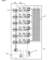
FIGURE 3 illustrates of the combination of a container to process solid organic waste, filter and pyrolysis chamber, exchanger and other components connected to the above; -
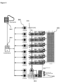
FIGURE 4 provides an illustrative representation of a container to process solid organic waste, filter and pyrolysis chamber, exchanger and other components connected to the above, with a complete overview over the sold organic waste process and system; -
FIGURE 5 illustrates a possible embodiment of the disclosure in which the processing of solid organic waste is automated and remotely controlled; - As already mentioned in the Background, systems and methods for processing solid organic waste have been introduced since a long time ago, but they were often extremely inefficient. The inefficiency was due to several factors, amongst which the impossibility to adequately control the level of temperature and humidity inside the container of solid organic waste and the waste of energy and resources to re-introduce inert material in the container of solid organic waste. Such and other inefficiencies led to the consumption, by the systems and methods of processing solid organic waste, of significantly more energy than the one which is produced.
- The present disclosure aims at solving the aforementioned inefficiency problem.
- The present disclosure includes a method to automatically and efficiently process solid organic waste by exploiting the natural characteristics of the waste, and in particular its changeable temperature and humidity. Such method is performed through the injection of solid organic waste in a thermically
isolable container 101 while keeping the temperature in the container between 30 and 85 °C and the level of humidity between 10% and 85%. The method involves conveying a resulting dried solid organic waste in a separate chamber where it is processed through pyrolysis while sending exhausts resulting from the above described processing to afilter 301 and charcoal is obtained at the end of the process. - The method further includes the monitoring of internal temperature and humidity through sensors placed in a rotable and remotely controlled container. In such embodiments of the disclosure, a set of parameters based on which humidity and temperature is adjusted is set in advance, so that when temperature and humidity exceed or drop below the standards that have been set of 35 and 85 °C and the level of humidity between 10 % and 85 % respectively, temperature and humidity are immediately brought back to the optimal set condition. The temperature of the solid organic waste is regulated also through the help of a
heat exchanger 104 connected to thecontainer 101, whichheat exchanger 104 is also used to cool the exhausts resulting from the drying process inside thecontainer 101 before they are sent to thefilter 301, so that their temperature is not too high for thefilter 301. The heat exchanger is used both to cool the temperature of the exhausts and in parallel to adjust the temperature of the inside of thecontainer 101, either increasing it or decreasing it. - In some of the embodiments, there is no need to pre-mix the solid organic waste with inert material because inert material is already present in the
container 101 and, in some embodiments, such inert material is constituted by the resulting dried solid organic waste of a previous cycle of processing itself. This method allows to save both time and energy by making the process extremely efficient. In some embodiments of the disclosure, sensors to monitor the right quantity of resulting solid organic waste are installed within therotable container 101 so that the right amount of resulting dried solid organic waste, which may range between 0 and 50 % of the resulting dried solid organic waste, is automatically left into thecontainer 101 after the originally inserted solid organic waste is dry enough that it can be sent to thepyrolysis chamber 402. In such embodiments, the level of dryness of the solid organic waste which is inserted in thecontainer 101 is monitored through sensors placed in thecontainer 101 so that the inside of thecontainer 101 does not have to be constantly checked from the outside, wasting energy and unbalancing the inside temperature. - Charcoal is obtained after the dried solid organic waste is sent to the
pyrolysis chamber 402. In one of the embodiments of the disclosure thefilter 301 is a biofilter and the resulting dried solid organic waste, after it is sent to thepyrolysis chamber 402, is transformed in biochar - In some of the embodiments of the disclosure, the
container 101 is rotated throughout the process in order to keep the levels of humidity and temperature between the optimal ranges indicated above and thanks to the sensors installed in thecontainer 101 the rotation happens not only at pre-fixed times but also automatically when there is a need to rotate. - A system to efficiently process solid organic waste involves the use of solid organic waste and of a thermically isolable container to dry the solid organic waste and to obtain a resulting dried solid organic waste, which is then sent to through a
pipe 105 and processed thanks to apyrolysis chamber 402. In such embodiment, the exhausts of the resulting dried solid organic waste is sent, through adedicated pipe 103, to afilter 301. Thecontainer 101 may further be equipped with sensors to monitor its humidity and temperature, which are regulated remotely thanks to a processing machine programmed withset parameters 503. The method uses aheat exchanger 104 that cools the exhausts coming from thecontainer 101 with the cold air that is introduced from outside through aventilator 106 and also comprises arotable container 101 that can be remotely controlled and which is pre-filled with resulting solid organic waste that acts as inert material. - The container has
multiple openings 102 to allow the injection of solid organic waste from three different positions, so that the solid organic waste is better distributed inside thecontainer 101. In one of the embodiments of the disclosure, there aremultiple containers 101 to process solid organic waste, all connected to thesame pyrolysis chamber 402 and to thesame filter 301 - The
heat exchanger 104, through which an external air used to lower the internal temperature of the container and the exhaust resulting from the treatment of the solid organic waste are respectively, and automatically, heated and cooled, is protected by a metallic net where the air enters in the container. The metallic net allows the pipes that work together with the heat exchanger to remain cleaner and it reduces the need to manually or automatically clean the pipes itself, making the process and system even more efficient. - In one of the embodiments of the disclosure, an
emergency heater 401 is envisaged, so that if the temperature inside thecontainer 101 drops below the indicated optimal range, the inside temperature can be brought back inside the range. In some embodiments of the disclosure, thanks to sensors installed inside the container, as soon as the temperature is detected to be outside the optimal range, air from outside pulled by aventilator 106 goes through theheat exchanger 104 and is injected into thecontainer 101 if the temperature is higher than it should be or extra hear from theemergency heater 401 is conveyed to the containers if temperature is below the optimal range. - In one of the embodiments of the disclosure, the method is completely automated from the injection of the solid organic waste into the
containers 101 through theopenings 102 to obtaining charcoal, even in the form of biochar. The automation takes place through sensors positioned inside and outside thecontainer 101 that monitor internal and external temperature, humidity, quantity of solid organic waste, quantity of resulting dried solid organic waste, and that are connected to I/O modules 501 connected to one or morerotating containers 101. In some embodiments, such I/O modules 501 collect data from external and internal sensors and send the data to aserver 503 every 200 m/s for complex elaborations, and based on such elaborations the rotation of thecontainer 101, the intake of air through theventilator 106, and in case through theheat exchanger 104, the passage through the heat exchanger of the exhausts, the conveyance of resulting dried solid organic waste to thepyrolysis chamber 402, the quantity of resulting dried solid organic waste that has to remain thecontainer 101 as inert material, the delivery of extra heat from theemergency heater 401 into thecontainer 101, and in any case each operation which involves any sort of measurement, are regulated. In some embodiments of the disclosure, theserver 503 and the I/O modules 501 are connected to anexternal cloud 502 for predictive maintenance, long-term data recording and alarm messages. - In one of the embodiments of the disclosure the
server 503 operates through PHP algorithms to control the I/O modules 501. In such embodiment theserver 503 manages all the components through the sensors and connects everycontainer 101 and every other component of the system and method together. In some embodiments, every second a script elaborates data and changes the system parameters in order to optimize the process efficiency, material flow and energy use. - The foregoing description of the embodiments of the invention has been presented for the purpose of illustration; it is not intended to be exhaustive or to limit the invention to the precise forms disclosed. Persons skilled in the relevant art can appreciate that many modifications and variations are possible in light of the above disclosure, within the scope of appended claims.
- Some portions of this description describe the embodiments of the invention in terms of algorithms and symbolic representations of operations on information. These algorithmic descriptions and representations are commonly used by those skilled in the data processing arts to convey the substance of their work effectively to others skilled in the art. These operations, while described functionally, computationally, or logically, are understood to be implemented by computer programs or equivalent electrical circuits, microcode, or the like. Furthermore, it has also proven convenient at times, to refer to these arrangements of operations as modules, without loss of generality. The described operations and their associated modules may be embodied in software, firmware, hardware, or any combinations thereof.
- Any of the steps, operations, or processes described herein may be performed or implemented with one or more hardware or software modules, alone or in combination with other devices. In one embodiment, a software module is implemented with a computer program product comprising a computer-readable medium containing computer program code, which can be executed by a computer processor for performing any or all of the steps, operations, or processes described.
- An apparatus for performing the operations of the claimed method may be specially constructed for the required purposes, and/or it may comprise a general-purpose computing device selectively activated or reconfigured by a computer program stored in the computer. Such a computer program may be stored in a tangible computer readable storage medium or any type of media suitable for storing electronic instructions, and coupled to a computer system bus. Furthermore, any computing systems referred to in the specification may include a single processor or may be architectures employing multiple processor designs for increased computing capability.
- A non-claimed computer data signal is a product that is presented in a tangible medium or carrier wave and modulated or otherwise encoded in the carrier wave, which is tangible, and transmitted according to any suitable transmission method.
- Finally, the language used in the specification has been principally selected for readability and instructional purposes, and it may not have been selected to delineate or circumscribe the inventive subject matter. It is therefore intended that the scope of the invention be limited not by this detailed description, but rather by any claims that issue on an application based hereon. Accordingly, the disclosure of the embodiments of the invention is intended to be illustrative, but not limiting, of the scope of the invention, which is set forth in the following claims.
- Unless the context clearly requires otherwise, throughout the description and the claims, the words "comprise," "comprising," and the like are to be construed in an inclusive sense (i.e., to say, in the sense of "including, but not limited to"), as opposed to an exclusive or exhaustive sense. As used herein, the terms "connected," "coupled," or any variant thereof means any connection or coupling, either direct or indirect, between two or more elements. Such a coupling or connection between the elements can be physical, logical, or a combination thereof. Additionally, the words "herein," "above," "below," and words of similar import, when used in this application, refer to this application as a whole and not to any particular portions of this application. Where the context permits, words in the above Detailed Description using the singular or plural number may also include the plural or singular number respectively. The word "or," in reference to a list of two or more items, covers all of the following interpretations of the word: any of the items in the list, all of the items in the list, and any combination of the items in the list.
- The above Detailed Description of examples of the invention is not intended to be exhaustive or to limit the invention to the precise form disclosed above. While specific examples for the invention are described above for illustrative purposes, various equivalent modifications are possible within the scope of the invention, as those skilled in the relevant art will recognize. While processes or blocks are presented in a given order in this application, alternative implementations may perform routines having steps performed in a different order, or employ systems having blocks in a different order. Some processes or blocks may be deleted, moved, added, subdivided, combined, and/or modified to provide alternative or sub-combinations. Also, while processes or blocks are at times shown as being performed in series, these processes or blocks may instead be performed or implemented in parallel, or may be performed at different times. Further any specific numbers noted herein are only examples. It is understood that alternative implementations may employ differing values or ranges.
- These and other changes can be made to the invention in light of the above Detailed Description. While the above description describes certain examples of the invention, and describes the best mode contemplated, no matter how detailed the above appears in text, the invention can be practiced in many ways. Accordingly, the actual scope of the invention encompasses not only the disclosed examples, but also all equivalent ways of practicing or implementing the invention under the claims.
Claims (9)
- A method to automatically and efficiently process solid organic waste comprising the steps of:injecting solid organic waste in a thermically isolable container (101);isolating the container (101);keeping the internal temperature of the container (101) between 35 and 85 °C and the humidity of the container (101) between 10% and 85%;monitoring the internal temperature and humidity of the container (101) through one or multiple sensors installed in the container (101);based on such monitoring, automatically adjusting humidity and temperature of the container (101) based on a given set of parameters;automatically rotating the container (101) based on a set of predetermined parameters;sending an exhaust resulting from the processing of the solid organic waste in the container (101) to a filter (301);conveying a resulting dried solid organic waste in a separate pyrolysis chamber where it is processed through pyrolysis;and characterised by further comprising the following steps:obtaining charcoal;providing the container (101) with multiple openings;- automatically heating an external air used to lower the internal temperature of the container (101) through a heat exchanger (104), and automatically cooling the exhaust resulting from the treatment of the solid organic waste through said heat exchanger (104);and further comprising the step of premixing an inert material to the solid organic waste before the solid organic waste is injected in the container (101);or comprising the step of leaving a predetermined part of the resulting dried solid organic waste in the container (101) instead of processing it through pyrolysis to act as inert material for a subsequent processing of solid organic waste.
- A method as in Claim 1 wherein an inert material is present in the container (101).
- A method as in Claim 2 wherein the inert material is the resulting dried solid organic waste.
- A method as in Claim 3 wherein the container (101) is completely insulated.
- A method as in Claim 3 wherein biochar is obtained.
- A method as in claim 1, comprising the step of providing the container (101) completely insulated.
- A method as in claim 1, comprising the step of providing the container (101) with multiple openings, to allow improved injection of solid organic waste.
- A method as in Claim 1 comprising the step of using metallic net when injecting air in the container (101).
- A method as in Claim 1 comprising the step of heating the solid organic waste inside the container (101) through an emergency heater (401).
Applications Claiming Priority (2)
| Application Number | Priority Date | Filing Date | Title |
|---|---|---|---|
| US201762554601P | 2017-09-06 | 2017-09-06 | |
| PCT/US2018/048377 WO2019050716A1 (en) | 2017-09-06 | 2018-08-28 | Efficient procedure and system to process solid organic waste |
Publications (4)
| Publication Number | Publication Date |
|---|---|
| EP3676223A1 EP3676223A1 (en) | 2020-07-08 |
| EP3676223A4 EP3676223A4 (en) | 2021-05-26 |
| EP3676223B1 true EP3676223B1 (en) | 2024-10-30 |
| EP3676223C0 EP3676223C0 (en) | 2024-10-30 |
Family
ID=65634482
Family Applications (1)
| Application Number | Title | Priority Date | Filing Date |
|---|---|---|---|
| EP18854431.6A Active EP3676223B1 (en) | 2017-09-06 | 2018-08-28 | Efficient procedure to process solid organic waste |
Country Status (3)
| Country | Link |
|---|---|
| US (1) | US11299678B2 (en) |
| EP (1) | EP3676223B1 (en) |
| WO (1) | WO2019050716A1 (en) |
Families Citing this family (6)
| Publication number | Priority date | Publication date | Assignee | Title |
|---|---|---|---|---|
| US11434160B1 (en) | 2020-09-01 | 2022-09-06 | Wm Intellectual Property Holdings, L.L.C. | System and method for processing of sewage sludge using pyrolysis to eliminate PFAS and other undesirable materials |
| CN113399432B (en) * | 2021-06-23 | 2022-04-29 | 华中科技大学 | A system and method for treating medical waste |
| EP4733275A1 (en) | 2024-10-22 | 2026-04-29 | BioForceTech Corporation | Plant and related process for treating organic material |
| EP4733276A1 (en) | 2024-10-22 | 2026-04-29 | BioForceTech Corporation | Plant and related process for treating organic material |
| EP4733274A1 (en) | 2024-10-22 | 2026-04-29 | BioForceTech Corporation | Plant and related process for treating organic material |
| EP4732967A1 (en) | 2024-10-22 | 2026-04-29 | BioForceTech Corporation | Plant and related process for treating organic material |
Family Cites Families (15)
| Publication number | Priority date | Publication date | Assignee | Title |
|---|---|---|---|---|
| GB1372466A (en) * | 1972-02-22 | 1974-10-30 | Cherwell Valley Silos | Processing spent coffee grounds |
| US4078973A (en) * | 1976-07-12 | 1978-03-14 | Occidental Petroleum Corporation | Loop pyrolysis process for organic solid wastes |
| US4465556A (en) | 1981-07-16 | 1984-08-14 | American Carbons, Inc. | Pyrolysis system with hot gas recirculation |
| FR2683543B1 (en) | 1991-11-08 | 1994-02-11 | Inst Francais Du Petrole | PROCESS FOR THERMAL PYROLYSIS OF HYDROCARBONS USING AN ELECTRIC OVEN. |
| US5409834A (en) * | 1993-04-06 | 1995-04-25 | Birdwell; Robert S. | Method and apparatus for removing pollutants from a source of polluted air |
| IT1276116B1 (en) | 1995-11-10 | 1997-10-24 | O E T Calusco S R L | PROCEDURE AND PLANT FOR THE PRODUCTION OF VEGETABLE COAL BY PYROLYSIS OF WOOD PRODUCTS OR VEGETABLE BIOMASS IN GENERAL |
| IL125137A (en) | 1998-06-29 | 2001-07-24 | Maavar Kb Recycling And Prodouction Of Carbon Ltd | Process for preparing activated carbon from urban waste |
| US6861169B2 (en) | 2001-05-09 | 2005-03-01 | Nuvera Fuel Cells, Inc. | Cogeneration of power and heat by an integrated fuel cell power system |
| PT10270U (en) * | 2007-12-04 | 2008-11-28 | Jorge Alberto Costa De Carvalho | PRODUCTION OF NEW THERMAL ENERGY, BY COLLECTION AND TRANSFER OF HEAT GENERATED IN AEROPIA DIGESTION PROCESS OF ORGANIC SOLID WASTE. |
| US8551294B2 (en) * | 2009-10-15 | 2013-10-08 | Feather N Time Corporation | Pyrolysis system for producing one or a combination of a solid, liquid and gaseous fuel |
| EP2450421B1 (en) * | 2010-11-03 | 2014-04-16 | BI ENERGY s.r.l. | Method for the production of a fuel from waste |
| WO2012097448A1 (en) * | 2011-01-19 | 2012-07-26 | Services Kengtek Inc. | Catalyst for distributed batch microwave pyrolysis, system and process thereof |
| US9388046B2 (en) * | 2011-04-15 | 2016-07-12 | Biogenic Reagents Ventures, Llc | Systems and apparatus for production of high-carbon biogenic reagents |
| CN105199757B (en) * | 2015-10-27 | 2017-11-03 | 神雾科技集团股份有限公司 | Pyrolysis system and method based on high-moisture organic waste |
| CN105907406A (en) * | 2016-05-11 | 2016-08-31 | 江苏润通生物科技有限公司 | Method for carbonizing organic solid waste by high-temperature coal gas to realize gas and charcoal co-production |
-
2018
- 2018-08-28 US US16/645,160 patent/US11299678B2/en active Active
- 2018-08-28 EP EP18854431.6A patent/EP3676223B1/en active Active
- 2018-08-28 WO PCT/US2018/048377 patent/WO2019050716A1/en not_active Ceased
Also Published As
| Publication number | Publication date |
|---|---|
| US11299678B2 (en) | 2022-04-12 |
| US20210032542A1 (en) | 2021-02-04 |
| EP3676223C0 (en) | 2024-10-30 |
| EP3676223A4 (en) | 2021-05-26 |
| WO2019050716A1 (en) | 2019-03-14 |
| EP3676223A1 (en) | 2020-07-08 |
Similar Documents
| Publication | Publication Date | Title |
|---|---|---|
| US11299678B2 (en) | Efficient procedure and system to process solid organic waste | |
| CN105132028A (en) | Crop straw continuous segmented pyrolysis circulation system | |
| KR102461887B1 (en) | A korean type connected silkworm nursery system | |
| CN206319897U (en) | Mine air intake well head humidity control system | |
| CN105009787B (en) | A kind of device of utilization united reaper waste heat drying grain during results | |
| CN103512326A (en) | Forest cone dryer | |
| CN101975683A (en) | Back blowing warming device in high-temperature smoke sampling system | |
| Ziegler et al. | Increasing the Energy Efficiency of Batch‐Type Drying with Partial Air Recirculation | |
| CN204902517U (en) | A drying -machine for chemical fertilizer production line | |
| CN103604291A (en) | Material drying control equipment and control method thereof | |
| KR101991652B1 (en) | Conveyor drying system for renewable energy | |
| CN104171056B (en) | Dark brownish green automation preliminary treatment method | |
| CN204707923U (en) | A kind of rice protein powder dries removal of impurities and cooling transportation integration apparatus | |
| CN208998422U (en) | A kind of freezer gas monitor and cleaning systems | |
| US20130125413A1 (en) | Method and control system for controlling supply of heat energy from a furnace to mulitple dryers | |
| CN220135991U (en) | A grain drying device that mixes fresh air heating and return air | |
| CN106288758A (en) | A kind of on-line checking grain moisture adjusts the drying machine of hot blast | |
| CN204811845U (en) | Dried fish boiling device | |
| CN104457192A (en) | Potassium-containing shale intermediate microwave processing device | |
| CN204408887U (en) | A kind of corn seed processing automatic control system | |
| CN104824785A (en) | Powder particle superheated steam continuous sterilization apparatus and control method thereof | |
| CN203768292U (en) | Rotation heat exchange dry distillation equipment | |
| CN204180805U (en) | A kind of donkey-hide gelatin jujube date drying machine | |
| CN105318676A (en) | a vacuum oven | |
| CN205611669U (en) | Automatic green grass or young crops machine of cooking over a slow fire of tealeaves |
Legal Events
| Date | Code | Title | Description |
|---|---|---|---|
| STAA | Information on the status of an ep patent application or granted ep patent |
Free format text: STATUS: THE INTERNATIONAL PUBLICATION HAS BEEN MADE |
|
| PUAI | Public reference made under article 153(3) epc to a published international application that has entered the european phase |
Free format text: ORIGINAL CODE: 0009012 |
|
| STAA | Information on the status of an ep patent application or granted ep patent |
Free format text: STATUS: REQUEST FOR EXAMINATION WAS MADE |
|
| 17P | Request for examination filed |
Effective date: 20200331 |
|
| AK | Designated contracting states |
Kind code of ref document: A1 Designated state(s): AL AT BE BG CH CY CZ DE DK EE ES FI FR GB GR HR HU IE IS IT LI LT LU LV MC MK MT NL NO PL PT RO RS SE SI SK SM TR |
|
| AX | Request for extension of the european patent |
Extension state: BA ME |
|
| RIN1 | Information on inventor provided before grant (corrected) |
Inventor name: VILLA, VALENTINO Inventor name: MOSCIARELLO, MARCO Inventor name: PESSINA, STEFANO Inventor name: BONFANTI, MATTIA Inventor name: PRESEZZI, DARIO |
|
| RIN1 | Information on inventor provided before grant (corrected) |
Inventor name: PESSINA, STEFANO Inventor name: PRESEZZI, DARIO Inventor name: VILLA, VALENTINO Inventor name: BONFANTI, MATTIA Inventor name: MOSCIARELLO, MARCO |
|
| DAV | Request for validation of the european patent (deleted) | ||
| DAX | Request for extension of the european patent (deleted) | ||
| RAP1 | Party data changed (applicant data changed or rights of an application transferred) |
Owner name: BIOFORCETECH CORPORATION |
|
| A4 | Supplementary search report drawn up and despatched |
Effective date: 20210429 |
|
| RIC1 | Information provided on ipc code assigned before grant |
Ipc: C01B 32/30 20170101AFI20210422BHEP Ipc: C10B 47/00 20060101ALI20210422BHEP Ipc: C10B 53/00 20060101ALI20210422BHEP Ipc: C10B 57/02 20060101ALI20210422BHEP |
|
| STAA | Information on the status of an ep patent application or granted ep patent |
Free format text: STATUS: EXAMINATION IS IN PROGRESS |
|
| 17Q | First examination report despatched |
Effective date: 20220426 |
|
| GRAP | Despatch of communication of intention to grant a patent |
Free format text: ORIGINAL CODE: EPIDOSNIGR1 |
|
| STAA | Information on the status of an ep patent application or granted ep patent |
Free format text: STATUS: GRANT OF PATENT IS INTENDED |
|
| INTG | Intention to grant announced |
Effective date: 20240610 |
|
| GRAS | Grant fee paid |
Free format text: ORIGINAL CODE: EPIDOSNIGR3 |
|
| GRAA | (expected) grant |
Free format text: ORIGINAL CODE: 0009210 |
|
| STAA | Information on the status of an ep patent application or granted ep patent |
Free format text: STATUS: THE PATENT HAS BEEN GRANTED |
|
| AK | Designated contracting states |
Kind code of ref document: B1 Designated state(s): AL AT BE BG CH CY CZ DE DK EE ES FI FR GB GR HR HU IE IS IT LI LT LU LV MC MK MT NL NO PL PT RO RS SE SI SK SM TR |
|
| REG | Reference to a national code |
Ref country code: GB Ref legal event code: FG4D |
|
| RIN1 | Information on inventor provided before grant (corrected) |
Inventor name: BONFANTI, MATTIA Inventor name: PESSINA, STEFANO Inventor name: MOSCIARELLO, MARCO Inventor name: VILLA, VALENTINO Inventor name: PRESEZZI, DARIO |
|
| REG | Reference to a national code |
Ref country code: CH Ref legal event code: EP |
|
| REG | Reference to a national code |
Ref country code: IE Ref legal event code: FG4D |
|
| REG | Reference to a national code |
Ref country code: DE Ref legal event code: R096 Ref document number: 602018076080 Country of ref document: DE |
|
| U01 | Request for unitary effect filed |
Effective date: 20241125 |
|
| U07 | Unitary effect registered |
Designated state(s): AT BE BG DE DK EE FI FR IT LT LU LV MT NL PT RO SE SI Effective date: 20241202 |
|
| PG25 | Lapsed in a contracting state [announced via postgrant information from national office to epo] |
Ref country code: HR Free format text: LAPSE BECAUSE OF FAILURE TO SUBMIT A TRANSLATION OF THE DESCRIPTION OR TO PAY THE FEE WITHIN THE PRESCRIBED TIME-LIMIT Effective date: 20241030 Ref country code: IS Free format text: LAPSE BECAUSE OF FAILURE TO SUBMIT A TRANSLATION OF THE DESCRIPTION OR TO PAY THE FEE WITHIN THE PRESCRIBED TIME-LIMIT Effective date: 20250228 |
|
| PG25 | Lapsed in a contracting state [announced via postgrant information from national office to epo] |
Ref country code: ES Free format text: LAPSE BECAUSE OF FAILURE TO SUBMIT A TRANSLATION OF THE DESCRIPTION OR TO PAY THE FEE WITHIN THE PRESCRIBED TIME-LIMIT Effective date: 20241030 |
|
| PG25 | Lapsed in a contracting state [announced via postgrant information from national office to epo] |
Ref country code: NO Free format text: LAPSE BECAUSE OF FAILURE TO SUBMIT A TRANSLATION OF THE DESCRIPTION OR TO PAY THE FEE WITHIN THE PRESCRIBED TIME-LIMIT Effective date: 20250130 |
|
| PG25 | Lapsed in a contracting state [announced via postgrant information from national office to epo] |
Ref country code: GR Free format text: LAPSE BECAUSE OF FAILURE TO SUBMIT A TRANSLATION OF THE DESCRIPTION OR TO PAY THE FEE WITHIN THE PRESCRIBED TIME-LIMIT Effective date: 20250131 |
|
| PG25 | Lapsed in a contracting state [announced via postgrant information from national office to epo] |
Ref country code: PL Free format text: LAPSE BECAUSE OF FAILURE TO SUBMIT A TRANSLATION OF THE DESCRIPTION OR TO PAY THE FEE WITHIN THE PRESCRIBED TIME-LIMIT Effective date: 20241030 |
|
| PG25 | Lapsed in a contracting state [announced via postgrant information from national office to epo] |
Ref country code: RS Free format text: LAPSE BECAUSE OF FAILURE TO SUBMIT A TRANSLATION OF THE DESCRIPTION OR TO PAY THE FEE WITHIN THE PRESCRIBED TIME-LIMIT Effective date: 20250130 |
|
| PG25 | Lapsed in a contracting state [announced via postgrant information from national office to epo] |
Ref country code: SM Free format text: LAPSE BECAUSE OF FAILURE TO SUBMIT A TRANSLATION OF THE DESCRIPTION OR TO PAY THE FEE WITHIN THE PRESCRIBED TIME-LIMIT Effective date: 20241030 |
|
| PG25 | Lapsed in a contracting state [announced via postgrant information from national office to epo] |
Ref country code: SK Free format text: LAPSE BECAUSE OF FAILURE TO SUBMIT A TRANSLATION OF THE DESCRIPTION OR TO PAY THE FEE WITHIN THE PRESCRIBED TIME-LIMIT Effective date: 20241030 |
|
| PG25 | Lapsed in a contracting state [announced via postgrant information from national office to epo] |
Ref country code: CZ Free format text: LAPSE BECAUSE OF FAILURE TO SUBMIT A TRANSLATION OF THE DESCRIPTION OR TO PAY THE FEE WITHIN THE PRESCRIBED TIME-LIMIT Effective date: 20241030 |
|
| PLBE | No opposition filed within time limit |
Free format text: ORIGINAL CODE: 0009261 |
|
| STAA | Information on the status of an ep patent application or granted ep patent |
Free format text: STATUS: NO OPPOSITION FILED WITHIN TIME LIMIT |
|
| U20 | Renewal fee for the european patent with unitary effect paid |
Year of fee payment: 8 Effective date: 20250820 |
|
| 26N | No opposition filed |
Effective date: 20250731 |
|
| PGFP | Annual fee paid to national office [announced via postgrant information from national office to epo] |
Ref country code: GB Payment date: 20250703 Year of fee payment: 8 |
|
| REG | Reference to a national code |
Ref country code: CH Ref legal event code: H13 Free format text: ST27 STATUS EVENT CODE: U-0-0-H10-H13 (AS PROVIDED BY THE NATIONAL OFFICE) Effective date: 20260324 |
|
| PG25 | Lapsed in a contracting state [announced via postgrant information from national office to epo] |
Ref country code: MC Free format text: LAPSE BECAUSE OF FAILURE TO SUBMIT A TRANSLATION OF THE DESCRIPTION OR TO PAY THE FEE WITHIN THE PRESCRIBED TIME-LIMIT Effective date: 20241030 |
|
| PG25 | Lapsed in a contracting state [announced via postgrant information from national office to epo] |
Ref country code: CH Free format text: LAPSE BECAUSE OF NON-PAYMENT OF DUE FEES Effective date: 20250831 |