EP3676133B1 - Occupant restraint adjustment and fastening apparatus - Google Patents
Occupant restraint adjustment and fastening apparatus Download PDFInfo
- Publication number
- EP3676133B1 EP3676133B1 EP18765987.5A EP18765987A EP3676133B1 EP 3676133 B1 EP3676133 B1 EP 3676133B1 EP 18765987 A EP18765987 A EP 18765987A EP 3676133 B1 EP3676133 B1 EP 3676133B1
- Authority
- EP
- European Patent Office
- Prior art keywords
- strap
- occupant restraint
- adjustment apparatus
- occupant
- clip
- Prior art date
- Legal status (The legal status is an assumption and is not a legal conclusion. Google has not performed a legal analysis and makes no representation as to the accuracy of the status listed.)
- Active
Links
Images












Classifications
-
- B—PERFORMING OPERATIONS; TRANSPORTING
- B60—VEHICLES IN GENERAL
- B60N—SEATS SPECIALLY ADAPTED FOR VEHICLES; VEHICLE PASSENGER ACCOMMODATION NOT OTHERWISE PROVIDED FOR
- B60N2/00—Seats specially adapted for vehicles; Arrangement or mounting of seats in vehicles
- B60N2/24—Seats specially adapted for vehicles; Arrangement or mounting of seats in vehicles for particular purposes or particular vehicles
- B60N2/26—Seats specially adapted for vehicles; Arrangement or mounting of seats in vehicles for particular purposes or particular vehicles for children
- B60N2/265—Adaptations for seat belts
-
- B—PERFORMING OPERATIONS; TRANSPORTING
- B60—VEHICLES IN GENERAL
- B60R—VEHICLES, VEHICLE FITTINGS, OR VEHICLE PARTS, NOT OTHERWISE PROVIDED FOR
- B60R22/00—Safety belts or body harnesses in vehicles
- B60R22/10—Safety belts or body harnesses in vehicles specially adapted for children or animals
- B60R22/105—Safety belts or body harnesses in vehicles specially adapted for children or animals for children
-
- A—HUMAN NECESSITIES
- A44—HABERDASHERY; JEWELLERY
- A44B—BUTTONS, PINS, BUCKLES, SLIDE FASTENERS, OR THE LIKE
- A44B11/00—Buckles; Similar fasteners for interconnecting straps or the like, e.g. for safety belts
- A44B11/25—Buckles; Similar fasteners for interconnecting straps or the like, e.g. for safety belts with two or more separable parts
- A44B11/2503—Safety buckles
- A44B11/2542—Safety buckles actuated by a rotatable element, e.g. combined with other actuating means
-
- A—HUMAN NECESSITIES
- A44—HABERDASHERY; JEWELLERY
- A44B—BUTTONS, PINS, BUCKLES, SLIDE FASTENERS, OR THE LIKE
- A44B11/00—Buckles; Similar fasteners for interconnecting straps or the like, e.g. for safety belts
- A44B11/25—Buckles; Similar fasteners for interconnecting straps or the like, e.g. for safety belts with two or more separable parts
- A44B11/2503—Safety buckles
- A44B11/2546—Details
- A44B11/2553—Attachment of buckle to strap
- A44B11/2557—Attachment of buckle to strap with strap length adjustment
-
- B—PERFORMING OPERATIONS; TRANSPORTING
- B60—VEHICLES IN GENERAL
- B60N—SEATS SPECIALLY ADAPTED FOR VEHICLES; VEHICLE PASSENGER ACCOMMODATION NOT OTHERWISE PROVIDED FOR
- B60N2/00—Seats specially adapted for vehicles; Arrangement or mounting of seats in vehicles
- B60N2/24—Seats specially adapted for vehicles; Arrangement or mounting of seats in vehicles for particular purposes or particular vehicles
- B60N2/26—Seats specially adapted for vehicles; Arrangement or mounting of seats in vehicles for particular purposes or particular vehicles for children
- B60N2/28—Seats readily mountable on, and dismountable from, existing seats or other parts of the vehicle
- B60N2/2803—Adaptations for seat belts
-
- B—PERFORMING OPERATIONS; TRANSPORTING
- B60—VEHICLES IN GENERAL
- B60N—SEATS SPECIALLY ADAPTED FOR VEHICLES; VEHICLE PASSENGER ACCOMMODATION NOT OTHERWISE PROVIDED FOR
- B60N2/00—Seats specially adapted for vehicles; Arrangement or mounting of seats in vehicles
- B60N2/24—Seats specially adapted for vehicles; Arrangement or mounting of seats in vehicles for particular purposes or particular vehicles
- B60N2/26—Seats specially adapted for vehicles; Arrangement or mounting of seats in vehicles for particular purposes or particular vehicles for children
- B60N2/28—Seats readily mountable on, and dismountable from, existing seats or other parts of the vehicle
- B60N2/2803—Adaptations for seat belts
- B60N2/2812—Adaptations for seat belts for securing the child to the child seat
-
- B—PERFORMING OPERATIONS; TRANSPORTING
- B60—VEHICLES IN GENERAL
- B60R—VEHICLES, VEHICLE FITTINGS, OR VEHICLE PARTS, NOT OTHERWISE PROVIDED FOR
- B60R22/00—Safety belts or body harnesses in vehicles
- B60R22/30—Coupling devices other than buckles, including length-adjusting fittings or anti-slip devices
-
- B—PERFORMING OPERATIONS; TRANSPORTING
- B62—LAND VEHICLES FOR TRAVELLING OTHERWISE THAN ON RAILS
- B62B—HAND-PROPELLED VEHICLES, e.g. HAND CARTS OR PERAMBULATORS; SLEDGES
- B62B9/00—Accessories or details specially adapted for children's carriages or perambulators
- B62B9/24—Safety guards for children, e.g. harness
Definitions
- the present invention is concerned with a restraint or strap adjustment and fastening apparatus for restraining an occupant and other items. More specifically, the present invention is concerned with an occupant restraint adjustment and fastening apparatus for a push chair, stroller, wheelchair or like transportation device or seat.
- restraining an occupant in a seat in an e.g. stroller or push chair is desirable.
- restraining a child prevents them from climbing out of the seat and thereby injuring themselves, particularly if the seat is on a push chair or stroller in transit.
- Five-point restraints are the most common, in which five strap portions are provided constructed from a flexible, but inextensible webbing material.
- Two shoulder portions pass from the seat, over the occupant's shoulders.
- Two waist portions pass around the occupant's waist, and a fifth groin portion extends from the seat base between the legs. All five strap portions meet at a central buckle.
- the buckle is permanently attached to the groin strap portion, and the shoulder and waist strap portions are releasably attached to the buckle.
- a common problem faced by the operators of such devices is the adjustment of the restraint.
- the need for adjustment stems from the requirement to have a well-fitting restraint. Loose restraints will not properly secure the occupant, and in the case of children they may wriggle free. In the event of an impact, or other sudden change in velocity or direction, the occupant may be ejected from the seat if the restraint is not tight enough. Therefore, there is a need to properly adjust the restrain to suit the size of the occupant. Adjustment is necessary in a number of scenarios.
- the seat may be used by a number of different sized occupants of different sizes, and / or ages at different times.
- an occupant's clothing may cause them to be larger or smaller.
- the operator may need to put a coat on the occupant.
- the bulkiness of the coat may result in the restraint being uncomfortably tight.
- the restraint may be too loose on the occupant.
- Existing restraints typically have some kind of adjustment mechanism. Such mechanisms are typically strap sliders provided on each strap portion (or at least some of them). Therefore individual adjustment of each strap portion is required to adjust the restraint. Further, strap sliders are difficult to use under tension, and, for example, adjustment of the strap portion with an occupant in-situ is difficult. It is more usual to unfasten the restraint, and possible remove the occupant before attempting adjustment, which is undesirable.
- a known seat and restraint assembly according to the preamble of claim 1 is disclosed in AU 200072375 A1 .
- an occupant restraint adjustment apparatus according to claim 1.
- the use of a "turn to tighten" control provides simple and easy adjustment for the operator.
- the use of rotation movement is also advantageous because it allows the strap adjustment to be geared, such that a high degree of adjustment can be achieved with a small rotation.
- a seat 10 comprising a seat back 12 and a seat pan 14. It will be understood that by “seat”, the present invention is not limited to any particular type of structure.
- the seat 10 may be part of a chair, vehicle, pushchair, stroller, wheelchair or any other type of structure, static or moveable, that an occupant can sit in or on.
- the terms front, rear, upper, lower and left and right will be referred to from the point of view of an occupant in the seat 100.
- the +Y direction is forward, or to the front, the +Z direction is up and the +X direction is towards the left.
- the apparatus 100 comprises an occupant restraint having a left strap 102, right strap 104 and a groin strap 106.
- Each strap 102, 104, 106 is constructed from standard seat belt webbing material such as woven nylon, polypropylene or polyester. Such materials in this form are flexible yet substantially inextensible and are well known in the art.
- the left strap 102 extends from an upper anchor point 108 on the upper left-hand side of the seat back to a lower anchor point 110 on the seat back, lower than the upper anchor point 108.
- the right strap 104 extends from an upper anchor point 112 on the upper righthand side of the seat back to a lower anchor point 114 on the seat back, lower than the upper anchor point 112.
- the groin strap 106 extends from a groin anchor point 116 on the seat pan 12.
- the apparatus 100 comprises two adjusters in the form of a left strap clip assembly 118 and a right strap clip assembly 120.
- the apparatus also comprises an actuation assembly in the form of a buckle 122.
- Each strap 102, 104 is fed through its respective strap clip assembly 118, 120. As such, each strap is divided into two portions.
- the left strap 102 comprises a left strap shoulder portion 124 extending from the upper anchor point 108 to the left strap clip assembly 118, and a left strap waist portion 126 extending from the left strap clip assembly 118 to the lower anchor point 110.
- the right strap 104 comprises a right strap shoulder portion 128 extending from the upper anchor point 112 to the right strap clip assembly 120 and a right strap waist portion 130 extending from the right strap clip assembly 120 to the lower anchor point 114.
- Each of the left and right straps 102, 104 has an effective strap length ESL as shown in Figure 2 with respect to the left strap 102.
- the effective strap length is variable depending on the operational state of the respective strap clip assembly (as will be described in detail below).
- the effective strap length is independent of the total length of webbing utilised in the strap between the upper and lower anchor point. This is known as the total strap webbing length TSWL. In all states of the apparatus 100, ESL ⁇ TSWL.
- the strap clip assemblies 118, 120 are identical with the exception that they are mirror images of each other. As such, the left strap clip assembly 118 will be described in detail, and the differences between it and the strap clip assembly 120 also described.
- FIG. 4 a detail view of the strap clip assembly 118 is provided.
- Figures 5 and 6 show exploded perspective views.
- Figure 7 shows a view with some parts removed.
- the left strap clip assembly 118 comprises an engagement member 132, a gear 134, a housing 136, a slide track 138, a first shaft 140, a second shaft 142 and a pulley 144.
- the engagement member 132 is shown in more detail in Figures 8a to 8c .
- the engagement member 132 is a unitary, hollow component constructed from e.g. an injection moulded plastics material. It has a projecting portion 146, a shoulder portion 148 and two projecting arms 150, 152.
- the engagement member 132 defines a first engagement direction 133.
- the projecting portion 146 is generally cuboidal in shape, having a front wall 154, a rear wall 156 and first and second sidewalls 158, 160.
- the four walls 154, 156, 158, 160 form a rectangle in cross section.
- the projecting portion defines a first opening 162 at a first, free, end and a second opening 164 at a second end where it meets the shoulder portion 148.
- the rear wall 156 projects past the first opening 162 to form a lip 166.
- the projecting portion has an inwardly tapered portion 168 towards the first opening when viewed from the front.
- the front wall 154 and rear wall 156 each define a shaft aperture 170, 172 respectively.
- the bearing apertures are therefore spaced apart, and are coaxial, lying on a gear axis 174, perpendicular to the first engagement direction 133.
- the rear wall 156 defines two opposed inwardly projecting notches 176, 178 each defining a respective abutment surface 180, 182.
- Two ridges 184, 186 are provided on each respective sidewall 158, 160 proximate the rear wall 156 and extend from the notches 176, 178 to meet the shoulder portion 148.
- the shoulder portion 148 is annular and generally rectangular in shape, being both wider and taller than the projecting portion 146.
- the shoulder portion defines a first shoulder surface 184 adjacent and facing in the same direction the projecting portion 146.
- the shoulder portion 148 defines a first region 186 proximate the projecting portion, and a second region 188 on the opposite side of the first region 186 to the projecting portion 146.
- the second region 186 is smaller than the first region 186 creating a second shoulder surface 190, opposite the first shoulder surface 184.
- the first and second arms 150, 152 project from the second region of the shoulder portion 148 in the opposite direction to the projecting portion 146, and opposite to the first engagement direction 133.
- Each 150, 152 arm has a respective free end 192, 194.
- An outwardly projecting stub shaft 196, 198 is defined at each respective free end.
- the stub shafts 196, 198 are coaxial, lying on a joint axis 200 which is perpendicular to both the first insertion direction 133 and the gear axis 174.
- Gear 134 is shown in detail in Figure 9 .
- Gear 134 is a unitary component, and constructed from metal.
- the gear 134 has an open bore 202 therethrough on the gear axis 174.
- the gear 134 defines a spur gear formation 204 defining a plurality of teeth 206.
- the housing 136 is shown in detail in Figure 10 .
- the housing 136 is a hollow, elongate component constructed from plastics material.
- the housing 136 defines a front wall 212, rear wall 214, and first and second sidewalls 216, 218.
- the walls 212, 214, 216, 218 define a rectangular cross-section such that the housing is generally cuboidal in shape.
- the rear wall joins a tapered end wall 220 which extends at an angle towards the front wall 212 forming a tapered end to the housing 136.
- a first strap opening 222 is disposed between the tapered end wall 212 and the front wall 212. The first strap opening 222 is narrow and elongate.
- a second strap opening 224 is defined in the rear wall.
- the second strap opening has a first leg 228 at an angle of 45 degrees to the first engagement direction, and a second leg 130 at an angle of 45 degrees to the first engagement direction.
- the legs 228, 230 are at 90 degrees to each other and thus form the second strap opening 224 in the shape of an "X".
- An engagement opening 226 is provided at the end of the housing 136 opposite the end defining the first strap opening 222.
- the second strap opening 224 is nearer to the engagement opening 226 than to the first strap opening 222.
- the slide track 138 is shown in detail in Figures 11a to 11c .
- the slide track 138 is constructed from a plastics material and is generally shaped as a "C" section component.
- the slide track defines a front wall 232 and first and second sidewalls 234, 236.
- the walls 232, 234, 236 define a C-shaped cross-section such that the slide track 138 forms an open channel.
- a wire guide 238 extends from the front wall 232 defining a closed loop.
- each sidewall 234, 238 meets the front wall 232 there is provided an elongate slide channel 240, 242 having a respective closed end 244, 246 and an open end 248, 250.
- each sidewall 234, 236 defines a respective bearing opening 252, 254 therethrough.
- the bearing openings 252, 254 are coaxial and lie on the joint axis 200.
- Each of the sidewalls further defines a respective first 256, 258, second 260, 262 and third 264, 266 shaft notch on the interior side thereof.
- the shaft notches are spaced apart along the first engagement direction 133.
- the shafts 140, 142 are cylindrical members constructed from metal material.
- the pulley 144 is shown in more detail in Figure 12 .
- the pulley 144 comprises a wire 268 (shown in Figures 5 to 7 ), a frame 270 and a pulley shaft 272.
- the wire 268 is a flexible yet inextensible component constructed from a metal material (e.g. steel wire).
- the frame 270 is generally "U" shaped and constructed from a plastics material.
- the frame 270 comprises a cross-member 274 with two parallel legs 276, 268 extending therefrom at either end.
- the cross-member 274 defines an aperture 280 therethough. Spanning the aperture 276 in the engagement direction 133 there is provided a cylindrical wire channel 282 being open at either end.
- Each leg 276, 278 defines a free end 284, 286.
- the pulley shaft 272 extends between the free ends 284, 286 of the legs 276, 278, perpendicular to the engagement direction 133.
- the strap clip assembly 118 is assembled as follows.
- the gear 134 is mounted in the projecting portion 146 of the engagement member 132 by means of a shaft (not shown) which lies on the gear axis 174.
- the shaft is a push fit with the shaft apertures 170, 172, and engages the open bore 202 of the gear 134 such that it is rotatable thereon.
- One end of the wire 268 is attached to the reel portion 208 of the gear 134 by means of the bore 210.
- the other end of the wire 268 feeds through the wire guide 238 in the housing, through the wire channel 282 in the frame 270 of the pulley 144 and attached thereto. Therefore the wire 268 forms a tension load path between the gear 134 and the pulley 144.
- the first shaft 140 is mounted into the slide track 138 by engagement with the first shaft notch 256 on the first sidewall 234, and the second shaft notch 262 on the second sidewall 236 such that the shaft 140 is at a 45 degree angle to the engagement direction 133 ( Figure 7 ).
- the second shaft engaged the respective third shaft notches 264, 266 of the first and second sidewalls 234, 236 such that it is normal to the engagement direction 133.
- the pulley 144 is assembled in sliding engagement with the slide track 138 by engaging the edges of the frame 270, and the two legs 276, 278 in the slide channels 240, 242. The pulley 144 is thus in free sliding engagement with the slide track 138 in the engagement direction 133.
- the slide track 138 is assembled with the engagement member 132 by elastically deforming the arms 150, 152 inwards and releasing them such that the stub shafts 196, 198 engage the bearing openings 252, 254. In this manner, the slide track 138 is pivotably relative to the engagement member 132 about the joint axis 200.
- the housing 134 engages the engagement member 132 by mating with the second region 188 of the shoulder portion 148.
- the second region 188 enters the engagement opening 226 such that the end of the housing 134 bears against the shoulder surface 190.
- the housing covers the slide track 138 and the components therein. Because the housing 134 is flexible, it permits pivoting of the slide track 138 relative to the engagement member 132.
- the left strap 102 engages the left strap clip assembly 118 as follows.
- the left strap 102 from the strap waist portion 126 passes through the second leg 230 of the second strap opening 224 in the housing 136. It wraps around the first shaft 144 ( Figure 7 ), turning though 90 degrees parallel to the engagement direction 133. The left strap 102 then passes on the rear side of the second shaft 142, looping through 180 degrees to face in the insertion direction 133. The left strap then loops around the pulley shaft 272, through 180 degrees to exit the housing 136 at the strap shoulder portion 124.
- the strap clip assembly 118 operates as follows.
- Rotation of the gear 134 about the gear axis 174 causes the wire 268 to wind around the reel portion 208. This tensions the wire 268 which pulls the pulley 144 in the engagement direction 133. The pulley 144 slides in the slide track 138 (the tension being reacted through the stub shafts 150, 152) towards the engagement member 132. This increases the distance between the pulley shaft 272 and the second shaft 142.
- the right strap clip assembly 120 is identical to the left strap clip assembly, with the exception that the first shaft 140 is mounted into the slide track 138 by engagement with the second shaft notch 158 on the first sidewall 234, and the first shaft notch 260 on the second sidewall 236.
- the right strap clip assembly 120 is therefore a mirror image of the left strap clip assembly 118.
- the buckle 122 comprises:
- the button 288 comprises a circular base 322 having a contact surface 324 and an underside 325 opposite the contact surface 324.
- a central shaft 326 extends from the geometric centre of the base 322 and defines an actuation axis 342.
- the central shaft 326 is generally in the shape of a stepped cylinder. It has a first portion 328 and a second portion 330 extending from the first portion 328.
- the second portion 330 has a diameter less than that of the first portion forming a shoulder 331.
- legs 334, 336, 338, 340 extend from the underside 325 of the base 322.
- the legs are proximate the outer edge of the base 322 and each describe a circle segment having approximately the same diameter as the base 322.
- Each leg spans a leg angle 344.
- the button spring 298 is a compression spring sized to receive the second portion 330 of the central shaft 326, but not the first portion 328.
- the button spring circlip 300 is sized to fit into the groove 332 and extend therefrom when installed.
- the dial is shown in detail in Figures 16a and 16b .
- the dial 305 is generally circular about the actuation axis 344.
- the dial 305 is constructed from a moulded plastics material.
- the dial 305 comprises a contact section 346 defining an annular front face 348 and a tapered face.
- the annular front face 348 contains a recessed base 368 thus defining a button receiving opening 369.
- the base defines a central bore 370 and four equally spaced leg openings 372, 374, 376, 378 which each describe a circle segment.
- the tapered face 350 is at the outer periphery of the annular front face 348.
- the tapered face 350 defines a series of shallow grooves 352 which extend simultaneously circumferentially and axially.
- a dial locking section 354 defining a plurality of axially and radially outwardly facing teeth 356.
- a drive section 358 having a plurality of radially outwardly facing gear teeth 360 forming a spur gear.
- the outer collar 362 is open ended.
- the inner collar 364 defines a core 366 in an endwall, being in communication with the bore 370.
- An annular region 380 is defined between the inner collar 364 and the outer collar 362.
- the dial spring 304 is a compression spring and is or larger diameter than the button spring 298.
- the first housing part 306 is shown in Figures 17a and 17b .
- the first housing part 306 is ring-shaped having an axially extending cylindrical sidewall 382 and a tapered annular wall 384 surrounding a central aperture 386.
- a plurality of locking teeth 388 are disposed on the underside of the tapered annular wall 384.
- a groin strap attachment protrusion 390 Extending radially outwardly from a first side of the sidewall 382 there is provided a groin strap attachment protrusion 390, and a left / right strap clip entry protrusion 392.
- the left / right strap clip entry protrusion 392 wraps around the outer surface of the sidewall 382, and defines a circle segment front surface 398, two endwalls 400, 402 and an upper wall 404.
- the upper wall 404 defines a left strap clip opening 406 and a right strap clip opening 408, with an axial groove 410 therebetween.
- the second housing part 308 is shown in Figures 18a and 18b .
- the second housing part 308 is generally flat having a base portion 412.
- the base portion 412 has a front surface 416 and a rear surface 414.
- a groin strap attachment protrusion 418 Extending radially outwardly from a first side of the base portion 412 there is provided a groin strap attachment protrusion 418, and a left / right strap clip entry protrusion 420.
- the groin strap attachment protrusion 418 comprises a strap bar 422 defining a slot 423.
- the left / right strap clip entry protrusion 420 comprises a flat left clip support surface 424 and a flat right clip support surface 426.
- a central collar 428 protrudes from the front surface 416 of the base 412 coaxial with the actuation axis 342.
- Two clip arm shaft apertures 430, 432 are provided in respective bosses in the second housing part 308 and define a clip arm pivot axis 442 therebetween.
- a first and second clip arm spring boss 434, 436 are also provided, projecting from the front surface 416 of the base portion 412.
- the spring bosses 434, 436 are provided between the clip arm shaft apertures, and the central collar 428.
- Each washer support 438, 440 defines a respective bore 444, 446.
- the first clip arm 310 is shown in Figures 19a and 19b .
- the first clip arm defines a front surface 474 and a rear surface 476. It comprises a generally semi-circular first body portion 448, and a radially extending second body portion 450.
- the first body portion 448 defines 180 degrees of an annulus.
- the second body portion 450 is straight and terminates in a boss 452 having an open bore 454 therethrough.
- a blind spring recess 472 where the first and second body portions 448, 450 meet.
- a washer notch 456 which is semi-circular in shape.
- an actuation member 458 extending axially from the front surface 474.
- the actuation member 458 is circle segment with an angle 478. The actuation member 458 extends to the free end of the first body portion 448.
- the clip 460 comprises a pair of spaced-apart arms 464, 466 with forwardly extending tabs 468, 470 extending normal thereto.
- the tabs 468, 470 define a clip recess 462 between them and the first body portion 448.
- the second clip arm 312 is a mirror image of the first clip arm 310.
- the first and second clip arm springs are compression springs.
- the first and second clip arm springs are metal washers.
- the buckle 122 is assembled as follows.
- the groin strap 106 can be looped through the strap bar 422, through the slot 423 and sewn to itself to attach the buckle 122 to the groin strap 106.
- the clip arm springs 314, 316 are mounted onto the clip arm spring bosses 434, 436.
- the clip arms 310, 312 are pivotably mounted to the second housing part 308 by passing a clip arm shaft between the clip arm shaft apertures 430, 432 through the open bores 454 on each clip arm 310, 312. In this way, the clip arms 310, 312 can pivot about the clip arm pivot axis 442.
- the clip arms 310, 312 are biased into a forward position (upward in Figure 20 ) by the springs 314, 316 (only the clip arm 312 is shown).
- the clip arm washers 318, 320 are installed on the clip arm washer supports 438, 440 such that they lie in the washer notches 456 of the clip arms 310, 312.
- the dial spring 304 is inserted into the central collar 428.
- the button 288 is assembled by threading the button spring 298 over the central shaft 326 so that it bears against the shoulder 331.
- the central shaft 326 and the spring 298 are then inserted into the bore 370 of the dial 302 and the button spring circlip 300 secured in the groove as the shaft 326 projects from the bore 366 of the dial 302.
- the legs 334, 336, 338, 340 of the button pass through the leg openings 372, 374, 376, 378 in the dial 302.
- the button can be depressed into the button receiving opening in the dial 302 but will resile under the action of the button spring 298.
- the dial 302 has been assembled with the second housing part 308 by inserting the central collar 428 of the second housing part 308 into the annular region 380 of the dial 302.
- the end face of the inner collar 364 bears against the dial spring 304 urging the dial into a forward position.
- the first housing part 306 is then assembled with the second housing part 308 to contain the mechanism within.
- the dial spring 304 urges the dial teeth 356 into engagement with the locking teeth 388 on the rear surface of the first housing part 306. This inhibits rotation of the dial 302.
- the groin strap 106 and buckle 122 are passed upwards, between the legs to the lap area.
- the occupant's arms are passed between each of the strap shoulder portions and strap waist portions respectively. It is assumed that the straps 102, 104 are at maximum effective length ESL max , i.e. per Figure 13a .
- the left strap clip assembly 118 is inserted into the left strap clip opening 406 in the first engagement direction 133.
- the projecting portion 146 of the engagement member 132 pushes the first clip arm 310 rearwards against the first clip arm spring 314 about the clip arm pivot axis 442. This is because the rear wall 156 of the projecting portion 146 bears against the tabs 468, 470.
- the tabs 468, 470 encounter the notches 176, 178 and resile into them under the action of the clip arm spring 314. In this engaged position, the tabs 468, 470 bear against the bearing surfaces 180, 182 and inhibit removal of the left strap clip assembly 118.
- the teeth 206 of the gear 134 engage the teeth 360 of the dial 302.
- the dial 302 In order to shorten the effective strap length ESL of each strap 102, 104 to properly fit the apparatus 100 to the occupant, the dial 302 is pressed rearwardly long the actuation axis 342 towards the second housing part 308. This compresses the dial spring 304 and disengages the locking teeth 356, 388 allowing rotation of the dial 302. Rotation of the dial 302 causes rotation of the gears 134 in each strap clip assembly because they are in mesh (as described above). This rotation simultaneously actuates the strap clip assemblies 118, 120 as described above, thus selective shortening the effective strap length (ESL) to tighten the straps 102, 104. It will be noted that the operator can also length the effective strap lengths by rotating the dial 302 in the opposite direction. Releasing the dial will re-engage the teeth 356, 388 under action of the dial spring 304, thus locking the apparatus 100 in the desired condition.
- the button 288 can be depressed. This causes the legs 334, 336, 338, 340 to move downwards.
- the legs 334, 336, 338, 340 are initially spaced from the actuation members 458 to avoid actuation when the dial is depressed. After this space is traversed, the legs will eventually contact the actuation members 458 of the clip arms 310, 312 to push the clip arms 310, 312 downwards against the bias of the clip arm springs 314, 316. This disengages the tabs 472, 474 from the notches 176, 178 and allows the strap clip assemblies 118, 120 to be removed.
- angle 344 of the legs 334, 336, 338, 340, and the angle 478 of the actuation members 458 is selected such that in all rotation positions of the dial, both the clip arms 310, 312 are depressed simultaneously.
- the button 288 is released, and resiles under the button spring 298.
- button spring 298 is selected to have a significantly lower spring constant than the dial spring such that depression of the button 288 does not cause depression of the dial 302.
- the system may be provided as a built-in / factory fitted option for products such as strollers, push chairs, strollers etc.
- the present invention may be provided as a retrofit or aftermarket sub-assembly for installation on a suitable seat by a user.
- the pulley 144 may be resiliently biased to return to the position in which the ESL is maximum (i.e. the position of Figure 13a ). This may be achieved by installing an elastic member between the upper end of the slide track and the pulley 144.
- the dial may be configured to rotate in one direction only.
- a ratchet may be provided between the dial 302 and the housing 306, 308. This would allow the apparatus to be tightened but not loosened. Loosening may be achieved by unclipping the strap clip assemblies and manually pulling the straps to slide the pulley 144 to the end of the slide track.
- An indicator may be provided on the strap clip assemblies to indicate the position of the pulley (and therefore what level of strap extension is present). This may be in the form of a slot or window in the housing 136 and slide track 138 so that the pulley 144 can be observed. Alternatively, small windows or apertures may be provided at the extremes of pulley travel. The pulley may be coloured e.g. red to indicate its position.
- the apparatus may be configured to avoid over-tightening.
- the dial teeth and gear teeth may be configured to ride over each other at a predetermined torque. This would provide an audible "clicking" to indicate that the torque, and therefore strap tension, was sufficient.
- a rotatable dial to adjust the length of the straps is adaptable to other locations.
- a dial may be provided behind the seat back and configured to shorten each shoulder strap.
- the dial may be provided to shorten both shoulder and / or waist and / or groin straps behind the seat back.
- the above embodiment may be modified to adjust the groin strap as well as the shoulder / waist straps.
- the waist straps may be directly attached to the buckle housing (like the groin strap).
- the free end of the shoulder strap would be attached to the first shafts of the strap clip assemblies such that adjustment of the apparatus adjusted the length of the shoulder straps only.
- the waist straps may also have strap clip assemblies.
- the shoulder / waist / groin strap clip assemblies may be geared differently to each other to provide variable adjustment.
- Actuation of the embodiment described above is manual.
- adjustment is performed by powered actuators, for example electrically powered actuators such as electric motors.
- Adjustment may be effected by means of an electronic controller.
- the occupant restraint apparatus is defined by the appended claims.
Landscapes
- Engineering & Computer Science (AREA)
- Mechanical Engineering (AREA)
- Health & Medical Sciences (AREA)
- Transportation (AREA)
- Child & Adolescent Psychology (AREA)
- General Health & Medical Sciences (AREA)
- Aviation & Aerospace Engineering (AREA)
- Public Health (AREA)
- Chemical & Material Sciences (AREA)
- Combustion & Propulsion (AREA)
- Seats For Vehicles (AREA)
Description
- The present invention is concerned with a restraint or strap adjustment and fastening apparatus for restraining an occupant and other items. More specifically, the present invention is concerned with an occupant restraint adjustment and fastening apparatus for a push chair, stroller, wheelchair or like transportation device or seat.
- It is well understood that restraining an occupant in a seat in an e.g. stroller or push chair is desirable. In particular, restraining a child prevents them from climbing out of the seat and thereby injuring themselves, particularly if the seat is on a push chair or stroller in transit. Five-point restraints are the most common, in which five strap portions are provided constructed from a flexible, but inextensible webbing material. Two shoulder portions pass from the seat, over the occupant's shoulders. Two waist portions pass around the occupant's waist, and a fifth groin portion extends from the seat base between the legs. All five strap portions meet at a central buckle. Typically, the buckle is permanently attached to the groin strap portion, and the shoulder and waist strap portions are releasably attached to the buckle.
- A common problem faced by the operators of such devices (which in the case of a push chair or stroller is typically not the occupant, but rather a parent or other carer) is the adjustment of the restraint. The need for adjustment stems from the requirement to have a well-fitting restraint. Loose restraints will not properly secure the occupant, and in the case of children they may wriggle free. In the event of an impact, or other sudden change in velocity or direction, the occupant may be ejected from the seat if the restraint is not tight enough. Therefore, there is a need to properly adjust the restrain to suit the size of the occupant. Adjustment is necessary in a number of scenarios.
- In a first scenario, as the child occupant grows, the restraint needs to be adjusted to accommodate. A two-year old child is usually significantly larger than a 6-month old child.
- In a second scenario, the seat may be used by a number of different sized occupants of different sizes, and / or ages at different times.
- In a third scenario, an occupant's clothing may cause them to be larger or smaller. For example, during unexpected rainfall, the operator may need to put a coat on the occupant. The bulkiness of the coat may result in the restraint being uncomfortably tight. Conversely, when a coat needs to be removed, the restraint may be too loose on the occupant.
- Existing restraints typically have some kind of adjustment mechanism. Such mechanisms are typically strap sliders provided on each strap portion (or at least some of them). Therefore individual adjustment of each strap portion is required to adjust the restraint. Further, strap sliders are difficult to use under tension, and, for example, adjustment of the strap portion with an occupant in-situ is difficult. It is more usual to unfasten the restraint, and possible remove the occupant before attempting adjustment, which is undesirable.
- A known seat and restraint assembly according to the preamble of claim 1 is disclosed in
AU 200072375 A1 - It is an aim of the present invention to overcome, or at least mitigate, the aforementioned problems.
- In accordance with the invention there is provided an occupant restraint adjustment apparatus according to claim 1.
- Advantageously, the use of a "turn to tighten" control provides simple and easy adjustment for the operator. The use of rotation movement is also advantageous because it allows the strap adjustment to be geared, such that a high degree of adjustment can be achieved with a small rotation.
- An example strap adjustment and fastening apparatus in accordance with the present invention will now be described with reference to the drawings in which:
-
Figure 1 is a perspective, schematic view of a seat having an occupant restraint adjustment and fastening apparatus in accordance with the present invention installed thereon; -
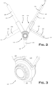
Figure 2 is a front view of the apparatus ofFigure 1 ; -
Figure 3 is a detail perspective view of a part of the apparatus ofFigure 1 ; -
Figure 4 is a perspective view of a first subassembly of the apparatus ofFigure 1 ; -
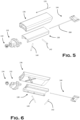
Figure 5 is a first perspective exploded view of the subassembly ofFigure 4 ; -
Figure 6 is a second perspective exploded view of the subassembly ofFigure 4 ; -
Figure 7 is a perspective view of a subset of components of the subassembly ofFigure 4 ; -
Figures 8a to 8c are various perspective views of a first component of the subassembly ofFigure 4 ; -
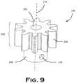
Figure 9 is a perspective view of a second component of the subassembly ofFigure 4 ; -
Figures 10a and 10b are various perspective views of a third component of the subassembly ofFigure 4 ; -
Figures 11a to 11c are various perspective views of a fourth component of the subassembly ofFigure 4 ; -
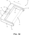
Figure 12 is a perspective view of a fifth component of the subassembly ofFigure 4 ; -
Figures 13a and 13b are similar toFigure 7 , and show the subset of components in two different conditions; -
Figure 14 is an exploded view of a second subassembly of the apparatus ofFigure 1 ; -
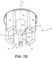
Figure 15 is a perspective view of a first component of the subassembly ofFigure 14 ; -
Figure 16a and 16b are perspective views of a second component of the subassembly ofFigure 14 ; -
Figure 17a and 17b are perspective views of a third component of the subassembly ofFigure 14 ; -
Figure 18a and 18b are perspective views of a fourth component of the subassembly ofFigure 14 ; -
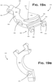
Figure 19a and 19b are perspective views of a fifth component of the subassembly ofFigure 14 ; -
Figure 20 is a front perspective view of the subassembly ofFigure 14 with some components removed; -
Figure 21 is a further front perspective view of the subassembly ofFigure 14 with some components removed; -
Figure 22 is a rear perspective view of the subassembly ofFigure 14 with some components removed; -
Figure 23 is a front perspective view of the subassembly ofFigure 14 in a first condition with some parts removed; and, -
Figure 24 is a front perspective view of the subassembly ofFigure 14 in a second condition with some parts removed. - Referring to
Figure 1 , there is shown schematically aseat 10 comprising aseat back 12 and aseat pan 14. It will be understood that by "seat", the present invention is not limited to any particular type of structure. Theseat 10 may be part of a chair, vehicle, pushchair, stroller, wheelchair or any other type of structure, static or moveable, that an occupant can sit in or on. - In the following description, the terms front, rear, upper, lower and left and right will be referred to from the point of view of an occupant in the
seat 100. As shown inFigure 1 , the +Y direction is forward, or to the front, the +Z direction is up and the +X direction is towards the left. - Attached to the
seat 10 there is provided an occupant restraint adjustment and fastening apparatus 100 (hereafter referred to as the "apparatus" 100). With reference toFigures 1 and2 , theapparatus 100 comprises an occupant restraint having aleft strap 102,right strap 104 and agroin strap 106. Eachstrap left strap 102 extends from anupper anchor point 108 on the upper left-hand side of the seat back to alower anchor point 110 on the seat back, lower than theupper anchor point 108. Theright strap 104 extends from anupper anchor point 112 on the upper righthand side of the seat back to alower anchor point 114 on the seat back, lower than theupper anchor point 112. Thegroin strap 106 extends from agroin anchor point 116 on theseat pan 12. - Referring to
Figures 2 and 3 , theapparatus 100 comprises two adjusters in the form of a leftstrap clip assembly 118 and a rightstrap clip assembly 120. The apparatus also comprises an actuation assembly in the form of abuckle 122. - Each
strap strap clip assembly left strap 102 comprises a leftstrap shoulder portion 124 extending from theupper anchor point 108 to the leftstrap clip assembly 118, and a leftstrap waist portion 126 extending from the leftstrap clip assembly 118 to thelower anchor point 110. Theright strap 104 comprises a rightstrap shoulder portion 128 extending from theupper anchor point 112 to the rightstrap clip assembly 120 and a rightstrap waist portion 130 extending from the rightstrap clip assembly 120 to thelower anchor point 114. - Each of the left and
right straps Figure 2 with respect to theleft strap 102. The effective strap length is variable depending on the operational state of the respective strap clip assembly (as will be described in detail below). The effective strap length is independent of the total length of webbing utilised in the strap between the upper and lower anchor point. This is known as the total strap webbing length TSWL. In all states of theapparatus 100, ESL < TSWL. - The
strap clip assemblies strap clip assembly 118 will be described in detail, and the differences between it and thestrap clip assembly 120 also described. - Referring to
Figure 4 , a detail view of thestrap clip assembly 118 is provided.Figures 5 and 6 show exploded perspective views.Figure 7 shows a view with some parts removed. - Referring to
Figures 5 and 6 , the leftstrap clip assembly 118 comprises anengagement member 132, agear 134, ahousing 136, aslide track 138, afirst shaft 140, asecond shaft 142 and apulley 144. - The
engagement member 132 is shown in more detail inFigures 8a to 8c . Theengagement member 132 is a unitary, hollow component constructed from e.g. an injection moulded plastics material. It has a projectingportion 146, ashoulder portion 148 and two projectingarms engagement member 132 defines afirst engagement direction 133. - The projecting
portion 146 is generally cuboidal in shape, having afront wall 154, arear wall 156 and first andsecond sidewalls walls first opening 162 at a first, free, end and asecond opening 164 at a second end where it meets theshoulder portion 148. Therear wall 156 projects past thefirst opening 162 to form alip 166. The projecting portion has an inwardly taperedportion 168 towards the first opening when viewed from the front. - The
front wall 154 andrear wall 156 each define ashaft aperture gear axis 174, perpendicular to thefirst engagement direction 133. Therear wall 156 defines two opposed inwardly projectingnotches respective abutment surface - Two
ridges respective sidewall rear wall 156 and extend from thenotches shoulder portion 148. - The
shoulder portion 148 is annular and generally rectangular in shape, being both wider and taller than the projectingportion 146. The shoulder portion defines afirst shoulder surface 184 adjacent and facing in the same direction the projectingportion 146. Theshoulder portion 148 defines afirst region 186 proximate the projecting portion, and asecond region 188 on the opposite side of thefirst region 186 to the projectingportion 146. Thesecond region 186 is smaller than thefirst region 186 creating asecond shoulder surface 190, opposite thefirst shoulder surface 184. - The first and
second arms shoulder portion 148 in the opposite direction to the projectingportion 146, and opposite to thefirst engagement direction 133. Each 150, 152 arm has a respectivefree end stub shaft stub shafts joint axis 200 which is perpendicular to both thefirst insertion direction 133 and thegear axis 174. - The
gear 134 is shown in detail inFigure 9 .Gear 134 is a unitary component, and constructed from metal. Thegear 134 has anopen bore 202 therethrough on thegear axis 174. Thegear 134 defines aspur gear formation 204 defining a plurality ofteeth 206. Adjacent to thespur gear formation 204 there is provided areel portion 208 defining abore 210 in a sidewall thereof, oriented normal to thegear axis 174. - The
housing 136 is shown in detail inFigure 10 . Thehousing 136 is a hollow, elongate component constructed from plastics material. Thehousing 136 defines afront wall 212,rear wall 214, and first andsecond sidewalls walls - At one end, the rear wall joins a
tapered end wall 220 which extends at an angle towards thefront wall 212 forming a tapered end to thehousing 136. Afirst strap opening 222 is disposed between thetapered end wall 212 and thefront wall 212. Thefirst strap opening 222 is narrow and elongate. - A second strap opening 224 is defined in the rear wall. The second strap opening has a
first leg 228 at an angle of 45 degrees to the first engagement direction, and asecond leg 130 at an angle of 45 degrees to the first engagement direction. Thelegs - An
engagement opening 226 is provided at the end of thehousing 136 opposite the end defining thefirst strap opening 222. The second strap opening 224 is nearer to theengagement opening 226 than to thefirst strap opening 222. - The
slide track 138 is shown in detail inFigures 11a to 11c . Theslide track 138 is constructed from a plastics material and is generally shaped as a "C" section component. - The slide track defines a
front wall 232 and first andsecond sidewalls walls slide track 138 forms an open channel. At a first end of theslide track 138, awire guide 238 extends from thefront wall 232 defining a closed loop. - On the inside of the
slide track 138, where eachsidewall front wall 232 there is provided anelongate slide channel closed end open end - Proximate each
closed end sidewall openings joint axis 200. - Each of the sidewalls further defines a respective first 256, 258, second 260, 262 and third 264, 266 shaft notch on the interior side thereof. The shaft notches are spaced apart along the
first engagement direction 133. - The
shafts - The
pulley 144 is shown in more detail inFigure 12 . Thepulley 144 comprises a wire 268 (shown inFigures 5 to 7 ), aframe 270 and apulley shaft 272. Thewire 268 is a flexible yet inextensible component constructed from a metal material (e.g. steel wire). Theframe 270 is generally "U" shaped and constructed from a plastics material. Theframe 270 comprises a cross-member 274 with twoparallel legs aperture 280 therethough. Spanning theaperture 276 in theengagement direction 133 there is provided acylindrical wire channel 282 being open at either end. Eachleg free end - The
pulley shaft 272 extends between the free ends 284, 286 of thelegs engagement direction 133. - The
strap clip assembly 118 is assembled as follows. - The
gear 134 is mounted in the projectingportion 146 of theengagement member 132 by means of a shaft (not shown) which lies on thegear axis 174. The shaft is a push fit with theshaft apertures open bore 202 of thegear 134 such that it is rotatable thereon. One end of thewire 268 is attached to thereel portion 208 of thegear 134 by means of thebore 210. - The other end of the
wire 268 feeds through thewire guide 238 in the housing, through thewire channel 282 in theframe 270 of thepulley 144 and attached thereto. Therefore thewire 268 forms a tension load path between thegear 134 and thepulley 144. - The
first shaft 140 is mounted into theslide track 138 by engagement with thefirst shaft notch 256 on thefirst sidewall 234, and thesecond shaft notch 262 on thesecond sidewall 236 such that theshaft 140 is at a 45 degree angle to the engagement direction 133 (Figure 7 ). - The second shaft engaged the respective
third shaft notches second sidewalls engagement direction 133. - The
pulley 144 is assembled in sliding engagement with theslide track 138 by engaging the edges of theframe 270, and the twolegs slide channels pulley 144 is thus in free sliding engagement with theslide track 138 in theengagement direction 133. - The
slide track 138 is assembled with theengagement member 132 by elastically deforming thearms stub shafts openings slide track 138 is pivotably relative to theengagement member 132 about thejoint axis 200. - The
housing 134 engages theengagement member 132 by mating with thesecond region 188 of theshoulder portion 148. Thesecond region 188 enters theengagement opening 226 such that the end of thehousing 134 bears against theshoulder surface 190. The housing covers theslide track 138 and the components therein. Because thehousing 134 is flexible, it permits pivoting of theslide track 138 relative to theengagement member 132. - The
left strap 102 engages the leftstrap clip assembly 118 as follows. - The
left strap 102, from thestrap waist portion 126 passes through thesecond leg 230 of the second strap opening 224 in thehousing 136. It wraps around the first shaft 144 (Figure 7 ), turning though 90 degrees parallel to theengagement direction 133. Theleft strap 102 then passes on the rear side of thesecond shaft 142, looping through 180 degrees to face in theinsertion direction 133. The left strap then loops around thepulley shaft 272, through 180 degrees to exit thehousing 136 at thestrap shoulder portion 124. - The
strap clip assembly 118 operates as follows. - Rotation of the
gear 134 about thegear axis 174 causes thewire 268 to wind around thereel portion 208. This tensions thewire 268 which pulls thepulley 144 in theengagement direction 133. Thepulley 144 slides in the slide track 138 (the tension being reacted through thestub shafts 150, 152) towards theengagement member 132. This increases the distance between thepulley shaft 272 and thesecond shaft 142. - Because the
left strap 102 needs to travel from thesecond shaft 142, to thepulley shaft 272 and back before it reaches thestrap shoulder portion 124, movement of the pulley by a distance D in the engagement direction ESL will shorten the effective strap length by 2D (although the total strap webbing length TSWL does not change). This is shown inFigures 13a and 13b . In the present embodiment, the range of adjustment is D = 60mm (i.e. total adjustment in ESL is 120mm). - The right
strap clip assembly 120 is identical to the left strap clip assembly, with the exception that thefirst shaft 140 is mounted into theslide track 138 by engagement with thesecond shaft notch 158 on thefirst sidewall 234, and thefirst shaft notch 260 on thesecond sidewall 236. The rightstrap clip assembly 120 is therefore a mirror image of the leftstrap clip assembly 118. - It will be noted that the
right strap 104 will enter the housing through thefirst leg 228 of the second strap opening 224 in thehousing 136. - An exploded view of the
buckle 122 is shown inFigure 14 . Thebuckle 122 comprises: - A
button 288; - A
button spring 298; - A
button spring circlip 300; - A
dial 302 - A
dial spring 304; - A
first housing part 306; - A
second housing part 308; - A
first clip arm 310; - A
second clip arm 312; - A first
clip arm spring 314; - A second
clip arm spring 316; - A first
clip arm washer 318; and, - A second
clip arm washer 320. - An underside view of the
button 288 is shown inFigure 15 . The button comprises a circular base 322 having a contact surface 324 and anunderside 325 opposite the contact surface 324. - A
central shaft 326 extends from the geometric centre of the base 322 and defines anactuation axis 342. Thecentral shaft 326 is generally in the shape of a stepped cylinder. It has afirst portion 328 and asecond portion 330 extending from thefirst portion 328. Thesecond portion 330 has a diameter less than that of the first portion forming ashoulder 331. At a free end of thesecond portion 330 there is provided acircumferential groove 332. - Four identical and equally spaced
legs underside 325 of the base 322. The legs are proximate the outer edge of the base 322 and each describe a circle segment having approximately the same diameter as the base 322. Each leg spans aleg angle 344. - The
button spring 298 is a compression spring sized to receive thesecond portion 330 of thecentral shaft 326, but not thefirst portion 328. - The
button spring circlip 300 is sized to fit into thegroove 332 and extend therefrom when installed. - The dial is shown in detail in
Figures 16a and 16b . The dial 305 is generally circular about theactuation axis 344. The dial 305 is constructed from a moulded plastics material. The dial 305 comprises acontact section 346 defining an annularfront face 348 and a tapered face. The annularfront face 348 contains a recessed base 368 thus defining abutton receiving opening 369. - The base defines a
central bore 370 and four equally spacedleg openings - The
tapered face 350 is at the outer periphery of the annularfront face 348. Thetapered face 350 defines a series ofshallow grooves 352 which extend simultaneously circumferentially and axially. - Rearward and outboard of the
contact section 346 there is provided adial locking section 354 defining a plurality of axially and radially outwardly facingteeth 356. - Rearward and radially inboard of the
dial locking section 354 there is provided adrive section 358 having a plurality of radially outwardly facinggear teeth 360 forming a spur gear. - Radially inboard of the
drive section 358 and extending from the base 368 there is provided anouter collar 362 and aninner collar 364. Theouter collar 362 is open ended. Theinner collar 364 defines a core 366 in an endwall, being in communication with thebore 370. Anannular region 380 is defined between theinner collar 364 and theouter collar 362. - The
dial spring 304 is a compression spring and is or larger diameter than thebutton spring 298. - The
first housing part 306 is shown inFigures 17a and 17b . Thefirst housing part 306 is ring-shaped having an axially extendingcylindrical sidewall 382 and a taperedannular wall 384 surrounding acentral aperture 386. A plurality of lockingteeth 388 are disposed on the underside of the taperedannular wall 384. - Extending radially outwardly from a first side of the
sidewall 382 there is provided a groinstrap attachment protrusion 390, and a left / right strapclip entry protrusion 392. - The left / right strap
clip entry protrusion 392 wraps around the outer surface of thesidewall 382, and defines a circlesegment front surface 398, twoendwalls upper wall 404. Theupper wall 404 defines a leftstrap clip opening 406 and a rightstrap clip opening 408, with an axial groove 410 therebetween. - The
second housing part 308 is shown inFigures 18a and 18b . Thesecond housing part 308 is generally flat having abase portion 412. Thebase portion 412 has afront surface 416 and arear surface 414. - Extending radially outwardly from a first side of the
base portion 412 there is provided a groinstrap attachment protrusion 418, and a left / right strapclip entry protrusion 420. - The groin
strap attachment protrusion 418 comprises astrap bar 422 defining a slot 423. - The left / right strap
clip entry protrusion 420 comprises a flat leftclip support surface 424 and a flat rightclip support surface 426. - A
central collar 428 protrudes from thefront surface 416 of the base 412 coaxial with theactuation axis 342. - Two clip
arm shaft apertures second housing part 308 and define a cliparm pivot axis 442 therebetween. - A first and second clip
arm spring boss front surface 416 of thebase portion 412. Thespring bosses central collar 428. - At diametrically opposed positions either side of the
collar 428 there are provide a first and second cliparm washer support washer support respective bore - The
first clip arm 310 is shown inFigures 19a and 19b . The first clip arm defines afront surface 474 and arear surface 476. It comprises a generally semi-circularfirst body portion 448, and a radially extendingsecond body portion 450. Thefirst body portion 448 defines 180 degrees of an annulus. Thesecond body portion 450 is straight and terminates in aboss 452 having anopen bore 454 therethrough. - On the rear surface there is provided a
blind spring recess 472 where the first andsecond body portions - At approximately halfway round the first body portion 448 (i.e. at about 90 degrees) there is provided a
washer notch 456 which is semi-circular in shape. - At the end of the
first body portion 448 opposite thesecond body portion 450, there is provided anactuation member 458 extending axially from thefront surface 474. Theactuation member 458 is circle segment with anangle 478. Theactuation member 458 extends to the free end of thefirst body portion 448. - Extending radially from the end of the
first body portion 448 there is provided aclip 460. Theclip 460 comprises a pair of spaced-apartarms tabs tabs clip recess 462 between them and thefirst body portion 448. - The
second clip arm 312 is a mirror image of thefirst clip arm 310. - The first and second clip arm springs are compression springs.
- The first and second clip arm springs are metal washers.
- The
buckle 122 is assembled as follows. - With reference to
Figure 20 , thegroin strap 106 can be looped through thestrap bar 422, through the slot 423 and sewn to itself to attach thebuckle 122 to thegroin strap 106. - The clip arm springs 314, 316 are mounted onto the clip
arm spring bosses clip arms second housing part 308 by passing a clip arm shaft between the cliparm shaft apertures open bores 454 on eachclip arm clip arms arm pivot axis 442. - It will be noted in
Figure 20 that thearms clip arms arm support surface tabs - The
clip arms Figure 20 ) by thesprings 314, 316 (only theclip arm 312 is shown). - The
clip arm washers washer notches 456 of theclip arms - The
dial spring 304 is inserted into thecentral collar 428. - As best shown in
Figure 14 , thebutton 288 is assembled by threading thebutton spring 298 over thecentral shaft 326 so that it bears against theshoulder 331. Thecentral shaft 326 and thespring 298 are then inserted into thebore 370 of thedial 302 and thebutton spring circlip 300 secured in the groove as theshaft 326 projects from the bore 366 of thedial 302. It will also be noted that thelegs leg openings dial 302. - In this way, the button can be depressed into the button receiving opening in the
dial 302 but will resile under the action of thebutton spring 298. - Referring to
Figure 21 , thedial 302 has been assembled with thesecond housing part 308 by inserting thecentral collar 428 of thesecond housing part 308 into theannular region 380 of thedial 302. The end face of theinner collar 364 bears against thedial spring 304 urging the dial into a forward position. - The
first housing part 306 is then assembled with thesecond housing part 308 to contain the mechanism within. Thedial spring 304 urges thedial teeth 356 into engagement with the lockingteeth 388 on the rear surface of thefirst housing part 306. This inhibits rotation of thedial 302. - Operation of the
buckle 122 is best understood in the context of the entire apparatus. - When it is desirable to fasten an occupant into the
seat 10, thegroin strap 106 and buckle 122 are passed upwards, between the legs to the lap area. The occupant's arms are passed between each of the strap shoulder portions and strap waist portions respectively. It is assumed that thestraps Figure 13a . - Referring to
Figure 23 , the leftstrap clip assembly 118 is inserted into the left strap clip opening 406 in thefirst engagement direction 133. As theclip assembly 118 enters the strap clip opening 406 the projectingportion 146 of theengagement member 132 pushes thefirst clip arm 310 rearwards against the firstclip arm spring 314 about the cliparm pivot axis 442. This is because therear wall 156 of the projectingportion 146 bears against thetabs - As the left
strap clip assembly 118 continues in thefirst engagement direction 133, thetabs notches clip arm spring 314. In this engaged position, thetabs strap clip assembly 118. When in this clipped condition, theteeth 206 of thegear 134 engage theteeth 360 of thedial 302. - The same action occurs for the right strap clip assembly. It will be noted that the provision of separately
actuable clip arms - In order to shorten the effective strap length ESL of each
strap apparatus 100 to the occupant, thedial 302 is pressed rearwardly long theactuation axis 342 towards thesecond housing part 308. This compresses thedial spring 304 and disengages the lockingteeth dial 302. Rotation of thedial 302 causes rotation of thegears 134 in each strap clip assembly because they are in mesh (as described above). This rotation simultaneously actuates thestrap clip assemblies straps dial 302 in the opposite direction. Releasing the dial will re-engage theteeth dial spring 304, thus locking theapparatus 100 in the desired condition. - When the occupant is ready to exit the seat, the
button 288 can be depressed. This causes thelegs legs actuation members 458 to avoid actuation when the dial is depressed. After this space is traversed, the legs will eventually contact theactuation members 458 of theclip arms clip arms tabs notches strap clip assemblies - It will be noted that the
angle 344 of thelegs angle 478 of theactuation members 458 is selected such that in all rotation positions of the dial, both theclip arms - Once the
clip arms button 288 is released, and resiles under thebutton spring 298. - It will be noted that the
button spring 298 is selected to have a significantly lower spring constant than the dial spring such that depression of thebutton 288 does not cause depression of thedial 302. - It will be noted that depression of the dial will not cause actuation of the
clip arms outer collar 362 of thedial 302 is selected to "bottom out" on the second housing before the legs of the button reach the actuation members. This is why the legs are spaced apart from theclip arms - Variations fall within the scope of the present invention.
- The above embodiment is described in-situ in a seat. It is envisaged that the system may be provided as a built-in / factory fitted option for products such as strollers, push chairs, strollers etc. Similarly, the present invention may be provided as a retrofit or aftermarket sub-assembly for installation on a suitable seat by a user.
- The
pulley 144 may be resiliently biased to return to the position in which the ESL is maximum (i.e. the position ofFigure 13a ). This may be achieved by installing an elastic member between the upper end of the slide track and thepulley 144. - The dial may be configured to rotate in one direction only. In other words, a ratchet may be provided between the
dial 302 and thehousing pulley 144 to the end of the slide track. - An indicator may be provided on the strap clip assemblies to indicate the position of the pulley (and therefore what level of strap extension is present). This may be in the form of a slot or window in the
housing 136 andslide track 138 so that thepulley 144 can be observed. Alternatively, small windows or apertures may be provided at the extremes of pulley travel. The pulley may be coloured e.g. red to indicate its position. - The apparatus may be configured to avoid over-tightening. For example, the dial teeth and gear teeth may be configured to ride over each other at a predetermined torque. This would provide an audible "clicking" to indicate that the torque, and therefore strap tension, was sufficient.
- The use of a rotatable dial to adjust the length of the straps is adaptable to other locations. For example, a dial may be provided behind the seat back and configured to shorten each shoulder strap. The dial may be provided to shorten both shoulder and / or waist and / or groin straps behind the seat back.
- The above embodiment may be modified to adjust the groin strap as well as the shoulder / waist straps.
- The waist straps may be directly attached to the buckle housing (like the groin strap). The free end of the shoulder strap would be attached to the first shafts of the strap clip assemblies such that adjustment of the apparatus adjusted the length of the shoulder straps only. Alternatively, the waist straps may also have strap clip assemblies. The shoulder / waist / groin strap clip assemblies may be geared differently to each other to provide variable adjustment.
- Actuation of the embodiment described above is manual. In a further embodiment, adjustment is performed by powered actuators, for example electrically powered actuators such as electric motors. Adjustment may be effected by means of an electronic controller.
- The occupant restraint apparatus is defined by the appended claims.
Claims (15)
- An occupant restraint apparatus (100) comprising:
an occupant restraint for restraining an occupant in use, the occupant restraint comprising:a first anchor point (108), a second anchor point (110), and a first strap (102) having an effective length extending between the first and second anchor points; and,an adjustment apparatus comprising:an actuation assembly (122) comprising a body (306) and a rotatable control (302);wherein the adjustment apparatus comprises an adjuster (118) comprising a body (136), a movable first member (144) mounted thereto, wherein the adjuster is assembled with the first strap (104), wherein movement of the movable member (144) relative to the body adjusts the effective length of the first strap; and,characterized in that rotation of the rotatable control (302) causes a flexible tension member (268) to be wound around a shaft (208), wherein the flexible tension member is connected to the movable first member (144) such that rotation of the rotatable control relative to the body of the actuation assembly moves the movable member of the adjuster relative to the body to shorten the effective length of the first strap and thereby actuate the adjuster to tighten the occupant restraint. - An occupant restraint adjustment apparatus (100) according to claim 1, in which the occupant restraint comprises a second strap (104), in which rotation of the rotatable control shortens the effective length of the second strap simultaneously with the first strap.
- An occupant restraint adjustment apparatus (100) according to claim 2, in which the first and second straps each comprise shoulder strap portions connectable to a shoulder anchor point.
- An occupant restraint adjustment apparatus (100) according to claim 3, in which the first and second straps (102, 104) each comprise waist strap portions (126, 130) connected to the shoulder strap portions, in which each waist strap portionis connectable to a waist anchor point (110, 114).
- An occupant restraint adjustment apparatus (100) according to any preceding claim, in which the occupant restraint comprises a third strap connected to the actuation assembly, which third strap comprises a groin strap portion.
- An occupant restraint adjustment apparatus (100) according to any preceding claim , in which the moveable first member is linearly moveable relative to the body.
- An occupant restraint adjustment apparatus (100) according to claim 6, in which the adjuster comprises:a second member mounted to the body; and,the first strap entering the body at a first position, looping around the first member, extending to and looping around the second member, and exiting the body at a second position spaced apart from the first, such that the strap forms an "S" shape;such that relative movement of the first member and the second member changes the effective length of the strap.
- An occupant restraint adjustment apparatus (100) according to any preceding claim, in which the adjuster comprises the flexible tension member and shaft.
- An occupant restraint adjustment apparatus (100) according to claim 8, comprising a drive formation between the rotatable member and the shaft.
- An occupant restraint adjustment apparatus (100) according to claim 9, in which the drive formation is a gear train.
- An occupant restraint adjustment apparatus (100) according to claim 10, in which the gear train comprises a first set of gear teeth on the rotatable member, and a second set of gear teeth on the shaft, the first and second set of gear teeth being in mesh.
- An occupant restraint adjustment apparatus (100) according to any preceding claim, in which the adjuster is selectively attachable to the actuation assembly.
- An occupant restraint adjustment apparatus (100) according to any preceding claim, in which the rotatable control (302) is linearly movable between a locked condition and a movable condition.
- An occupant restraint adjustment apparatus (100) according to claim 13, in which the rotatable control (302) is resiliently biased into the locked condition.
- An occupant seat comprising an occupant restraint adjustment apparatus (100) according to any preceding claim.
Applications Claiming Priority (2)
| Application Number | Priority Date | Filing Date | Title |
|---|---|---|---|
| GB1714028.6A GB2566260A (en) | 2017-09-01 | 2017-09-01 | Occupant restraint adjustment and fastening apparatus |
| PCT/GB2018/052433 WO2019043376A1 (en) | 2017-09-01 | 2018-08-29 | Occupant restraint adjustment and fastening apparatus |
Publications (3)
| Publication Number | Publication Date |
|---|---|
| EP3676133A1 EP3676133A1 (en) | 2020-07-08 |
| EP3676133B1 true EP3676133B1 (en) | 2023-06-07 |
| EP3676133C0 EP3676133C0 (en) | 2023-06-07 |
Family
ID=60050592
Family Applications (1)
| Application Number | Title | Priority Date | Filing Date |
|---|---|---|---|
| EP18765987.5A Active EP3676133B1 (en) | 2017-09-01 | 2018-08-29 | Occupant restraint adjustment and fastening apparatus |
Country Status (4)
| Country | Link |
|---|---|
| US (1) | US11324288B2 (en) |
| EP (1) | EP3676133B1 (en) |
| GB (1) | GB2566260A (en) |
| WO (1) | WO2019043376A1 (en) |
Families Citing this family (5)
| Publication number | Priority date | Publication date | Assignee | Title |
|---|---|---|---|---|
| GB2566260A (en) * | 2017-09-01 | 2019-03-13 | Care4Futures Ltd | Occupant restraint adjustment and fastening apparatus |
| CN110254307A (en) * | 2019-06-28 | 2019-09-20 | 救援宝贝有限公司 | Child seat with medical aid |
| CN115667048A (en) * | 2020-05-21 | 2023-01-31 | 格莱科儿童用品有限公司 | Winch systems for child restraints |
| CN114701411B (en) * | 2022-03-17 | 2023-06-20 | 安徽鸿贝智能科技有限公司 | Protective belt connecting hook piece for child seat |
| GB2622077B (en) * | 2022-09-01 | 2024-12-25 | Care4Futures Ltd | Strap tensioner and tension indicator |
Family Cites Families (18)
| Publication number | Priority date | Publication date | Assignee | Title |
|---|---|---|---|---|
| US4656700A (en) * | 1985-12-02 | 1987-04-14 | American Safety Equipment Corporation | Lightweight, multiple-point, quick-release, safety buckle for body harnesses |
| EP0295838A1 (en) * | 1987-06-17 | 1988-12-21 | Britax Child-Care Products Pty Ltd. | Harness adjuster for child's seat |
| DE4105725C1 (en) * | 1991-02-23 | 1992-05-07 | Mercedes-Benz Aktiengesellschaft, 7000 Stuttgart, De | Securing belt tensioning mechanism - uses rollers urged towards each other by turning knob |
| NL9500024A (en) * | 1995-01-05 | 1996-08-01 | Mach En Metaalfab Oedremefaoe | Child's safety seat |
| AU768142B2 (en) | 1999-12-21 | 2003-12-04 | Autoliv Australia Pty Ltd | Seat/restraint assembly |
| US7252342B2 (en) * | 2004-04-13 | 2007-08-07 | Graco Children's Products Inc. | Child restraint assembly for child vehicle seat |
| WO2007030865A1 (en) * | 2005-09-13 | 2007-03-22 | Igc (Australia) Pty Ltd | Harness buckle |
| CN201304957Y (en) * | 2008-08-18 | 2009-09-09 | 明门实业股份有限公司 | Safety belt adjusting device |
| US8371425B2 (en) * | 2008-10-30 | 2013-02-12 | Ford Global Technologies, Llc | Dynamic displacement energy management device |
| WO2012037398A2 (en) * | 2010-09-15 | 2012-03-22 | Amsafe Commerical Products, Inc. | Occupant restraint systems having tensioning devices, and associated methods of use manufacture |
| US9993048B2 (en) | 2015-06-10 | 2018-06-12 | D B Industries, Llc | Safety harness connector assembly |
| US20180271224A1 (en) * | 2017-03-24 | 2018-09-27 | Chin-Sung Huang | Buckle Structure for Seat Belt of Vehicle |
| US10974690B2 (en) * | 2017-08-30 | 2021-04-13 | Evenflo Company, Inc. | Ratchet adjuster for latch connector |
| GB2566260A (en) * | 2017-09-01 | 2019-03-13 | Care4Futures Ltd | Occupant restraint adjustment and fastening apparatus |
| US10513241B2 (en) * | 2017-12-21 | 2019-12-24 | Toyota Motor Engineering & Manufacturing North America, Inc. | Compact force limiter for automotive safety restraints |
| CN107985490B (en) * | 2018-01-03 | 2024-01-26 | 陶月强 | Scooter baby carriage |
| DE102018123026A1 (en) * | 2018-09-19 | 2020-03-19 | Fidlock Gmbh | Locking device with attachable locking parts |
| CN112092767A (en) * | 2020-10-19 | 2020-12-18 | 广西宁达汽车科技有限公司 | Vehicle safety belt buckle |
-
2017
- 2017-09-01 GB GB1714028.6A patent/GB2566260A/en not_active Withdrawn
-
2018
- 2018-08-29 EP EP18765987.5A patent/EP3676133B1/en active Active
- 2018-08-29 WO PCT/GB2018/052433 patent/WO2019043376A1/en not_active Ceased
- 2018-08-29 US US16/643,570 patent/US11324288B2/en active Active
Also Published As
| Publication number | Publication date |
|---|---|
| US11324288B2 (en) | 2022-05-10 |
| WO2019043376A1 (en) | 2019-03-07 |
| EP3676133C0 (en) | 2023-06-07 |
| US20200196712A1 (en) | 2020-06-25 |
| GB2566260A (en) | 2019-03-13 |
| GB201714028D0 (en) | 2017-10-18 |
| EP3676133A1 (en) | 2020-07-08 |
Similar Documents
| Publication | Publication Date | Title |
|---|---|---|
| EP3676133B1 (en) | Occupant restraint adjustment and fastening apparatus | |
| CA2151087C (en) | A child seat for a vehicle and a seat belt system for the child seat | |
| US8944503B2 (en) | Child safety seat harness tensioning device | |
| US8967715B2 (en) | Anchor latch system for child restraint systems and child car safety seats | |
| US9775410B2 (en) | Web adjusters for use with restraint systems and associated methods of use and manufacture | |
| US8141950B2 (en) | Single retractor lower anchor connection system | |
| US8955915B2 (en) | Child safety seat having an adjustable crotch strap | |
| CA2038505C (en) | Low profile web adjuster | |
| CA2526156C (en) | Child restraint system with automatic and manual harness tightening | |
| EP2391524B1 (en) | Child safety seat with height adjust able harness and headrest | |
| CN209955940U (en) | Seat belt connector tongue assembly and seat belt assembly | |
| EP4054902B1 (en) | Safety belt automatic adjustment apparatus and child safety seat therewith | |
| JPH09511719A (en) | Integrated child seat that automatically accepts the size of a child | |
| US6053532A (en) | Multi-point pretensioner system | |
| JP2015202864A (en) | Restraining system for vehicle | |
| US20060261649A1 (en) | Web adjuster and harness for child restraint seat | |
| WO1986002050A1 (en) | Child safety seat | |
| US20030071511A1 (en) | Belt tensioning mechanism | |
| US9033369B2 (en) | Holding covers for seat belt attachment | |
| CN117284236A (en) | Child safety seat and its seat belt adjustment system | |
| JP2005053375A (en) | Infant seat mounting structure and infant seat mounting method |
Legal Events
| Date | Code | Title | Description |
|---|---|---|---|
| STAA | Information on the status of an ep patent application or granted ep patent |
Free format text: STATUS: UNKNOWN |
|
| STAA | Information on the status of an ep patent application or granted ep patent |
Free format text: STATUS: THE INTERNATIONAL PUBLICATION HAS BEEN MADE |
|
| PUAI | Public reference made under article 153(3) epc to a published international application that has entered the european phase |
Free format text: ORIGINAL CODE: 0009012 |
|
| STAA | Information on the status of an ep patent application or granted ep patent |
Free format text: STATUS: REQUEST FOR EXAMINATION WAS MADE |
|
| 17P | Request for examination filed |
Effective date: 20200415 |
|
| AK | Designated contracting states |
Kind code of ref document: A1 Designated state(s): AL AT BE BG CH CY CZ DE DK EE ES FI FR GB GR HR HU IE IS IT LI LT LU LV MC MK MT NL NO PL PT RO RS SE SI SK SM TR |
|
| AX | Request for extension of the european patent |
Extension state: BA ME |
|
| DAV | Request for validation of the european patent (deleted) | ||
| DAX | Request for extension of the european patent (deleted) | ||
| STAA | Information on the status of an ep patent application or granted ep patent |
Free format text: STATUS: EXAMINATION IS IN PROGRESS |
|
| 17Q | First examination report despatched |
Effective date: 20201222 |
|
| GRAP | Despatch of communication of intention to grant a patent |
Free format text: ORIGINAL CODE: EPIDOSNIGR1 |
|
| STAA | Information on the status of an ep patent application or granted ep patent |
Free format text: STATUS: GRANT OF PATENT IS INTENDED |
|
| INTG | Intention to grant announced |
Effective date: 20221013 |
|
| GRAS | Grant fee paid |
Free format text: ORIGINAL CODE: EPIDOSNIGR3 |
|
| GRAA | (expected) grant |
Free format text: ORIGINAL CODE: 0009210 |
|
| STAA | Information on the status of an ep patent application or granted ep patent |
Free format text: STATUS: THE PATENT HAS BEEN GRANTED |
|
| AK | Designated contracting states |
Kind code of ref document: B1 Designated state(s): AL AT BE BG CH CY CZ DE DK EE ES FI FR GB GR HR HU IE IS IT LI LT LU LV MC MK MT NL NO PL PT RO RS SE SI SK SM TR |
|
| REG | Reference to a national code |
Ref country code: GB Ref legal event code: FG4D |
|
| REG | Reference to a national code |
Ref country code: CH Ref legal event code: EP Ref country code: AT Ref legal event code: REF Ref document number: 1574081 Country of ref document: AT Kind code of ref document: T Effective date: 20230615 |
|
| REG | Reference to a national code |
Ref country code: DE Ref legal event code: R096 Ref document number: 602018051165 Country of ref document: DE |
|
| U01 | Request for unitary effect filed |
Effective date: 20230628 |
|
| U07 | Unitary effect registered |
Designated state(s): AT BE BG DE DK EE FI FR IT LT LU LV MT NL PT SE SI Effective date: 20230706 |
|
| REG | Reference to a national code |
Ref country code: LT Ref legal event code: MG9D |
|
| U20 | Renewal fee for the european patent with unitary effect paid |
Year of fee payment: 6 Effective date: 20230831 |
|
| PG25 | Lapsed in a contracting state [announced via postgrant information from national office to epo] |
Ref country code: NO Free format text: LAPSE BECAUSE OF FAILURE TO SUBMIT A TRANSLATION OF THE DESCRIPTION OR TO PAY THE FEE WITHIN THE PRESCRIBED TIME-LIMIT Effective date: 20230907 Ref country code: ES Free format text: LAPSE BECAUSE OF FAILURE TO SUBMIT A TRANSLATION OF THE DESCRIPTION OR TO PAY THE FEE WITHIN THE PRESCRIBED TIME-LIMIT Effective date: 20230607 |
|
| PG25 | Lapsed in a contracting state [announced via postgrant information from national office to epo] |
Ref country code: RS Free format text: LAPSE BECAUSE OF FAILURE TO SUBMIT A TRANSLATION OF THE DESCRIPTION OR TO PAY THE FEE WITHIN THE PRESCRIBED TIME-LIMIT Effective date: 20230607 Ref country code: HR Free format text: LAPSE BECAUSE OF FAILURE TO SUBMIT A TRANSLATION OF THE DESCRIPTION OR TO PAY THE FEE WITHIN THE PRESCRIBED TIME-LIMIT Effective date: 20230607 Ref country code: GR Free format text: LAPSE BECAUSE OF FAILURE TO SUBMIT A TRANSLATION OF THE DESCRIPTION OR TO PAY THE FEE WITHIN THE PRESCRIBED TIME-LIMIT Effective date: 20230908 |
|
| PG25 | Lapsed in a contracting state [announced via postgrant information from national office to epo] |
Ref country code: SK Free format text: LAPSE BECAUSE OF FAILURE TO SUBMIT A TRANSLATION OF THE DESCRIPTION OR TO PAY THE FEE WITHIN THE PRESCRIBED TIME-LIMIT Effective date: 20230607 |
|
| PG25 | Lapsed in a contracting state [announced via postgrant information from national office to epo] |
Ref country code: IS Free format text: LAPSE BECAUSE OF FAILURE TO SUBMIT A TRANSLATION OF THE DESCRIPTION OR TO PAY THE FEE WITHIN THE PRESCRIBED TIME-LIMIT Effective date: 20231007 |
|
| PG25 | Lapsed in a contracting state [announced via postgrant information from national office to epo] |
Ref country code: SM Free format text: LAPSE BECAUSE OF FAILURE TO SUBMIT A TRANSLATION OF THE DESCRIPTION OR TO PAY THE FEE WITHIN THE PRESCRIBED TIME-LIMIT Effective date: 20230607 Ref country code: SK Free format text: LAPSE BECAUSE OF FAILURE TO SUBMIT A TRANSLATION OF THE DESCRIPTION OR TO PAY THE FEE WITHIN THE PRESCRIBED TIME-LIMIT Effective date: 20230607 Ref country code: RO Free format text: LAPSE BECAUSE OF FAILURE TO SUBMIT A TRANSLATION OF THE DESCRIPTION OR TO PAY THE FEE WITHIN THE PRESCRIBED TIME-LIMIT Effective date: 20230607 Ref country code: IS Free format text: LAPSE BECAUSE OF FAILURE TO SUBMIT A TRANSLATION OF THE DESCRIPTION OR TO PAY THE FEE WITHIN THE PRESCRIBED TIME-LIMIT Effective date: 20231007 Ref country code: CZ Free format text: LAPSE BECAUSE OF FAILURE TO SUBMIT A TRANSLATION OF THE DESCRIPTION OR TO PAY THE FEE WITHIN THE PRESCRIBED TIME-LIMIT Effective date: 20230607 |
|
| PG25 | Lapsed in a contracting state [announced via postgrant information from national office to epo] |
Ref country code: PL Free format text: LAPSE BECAUSE OF FAILURE TO SUBMIT A TRANSLATION OF THE DESCRIPTION OR TO PAY THE FEE WITHIN THE PRESCRIBED TIME-LIMIT Effective date: 20230607 |
|
| REG | Reference to a national code |
Ref country code: DE Ref legal event code: R097 Ref document number: 602018051165 Country of ref document: DE |
|
| PG25 | Lapsed in a contracting state [announced via postgrant information from national office to epo] |
Ref country code: MC Free format text: LAPSE BECAUSE OF FAILURE TO SUBMIT A TRANSLATION OF THE DESCRIPTION OR TO PAY THE FEE WITHIN THE PRESCRIBED TIME-LIMIT Effective date: 20230607 |
|
| REG | Reference to a national code |
Ref country code: CH Ref legal event code: PL |
|
| PG25 | Lapsed in a contracting state [announced via postgrant information from national office to epo] |
Ref country code: MC Free format text: LAPSE BECAUSE OF FAILURE TO SUBMIT A TRANSLATION OF THE DESCRIPTION OR TO PAY THE FEE WITHIN THE PRESCRIBED TIME-LIMIT Effective date: 20230607 |
|
| PLBE | No opposition filed within time limit |
Free format text: ORIGINAL CODE: 0009261 |
|
| STAA | Information on the status of an ep patent application or granted ep patent |
Free format text: STATUS: NO OPPOSITION FILED WITHIN TIME LIMIT |
|
| PG25 | Lapsed in a contracting state [announced via postgrant information from national office to epo] |
Ref country code: CH Free format text: LAPSE BECAUSE OF NON-PAYMENT OF DUE FEES Effective date: 20230831 |
|
| 26N | No opposition filed |
Effective date: 20240308 |
|
| REG | Reference to a national code |
Ref country code: IE Ref legal event code: MM4A |
|
| PG25 | Lapsed in a contracting state [announced via postgrant information from national office to epo] |
Ref country code: IE Free format text: LAPSE BECAUSE OF NON-PAYMENT OF DUE FEES Effective date: 20230829 |
|
| U20 | Renewal fee for the european patent with unitary effect paid |
Year of fee payment: 7 Effective date: 20240612 |
|
| PG25 | Lapsed in a contracting state [announced via postgrant information from national office to epo] |
Ref country code: IE Free format text: LAPSE BECAUSE OF NON-PAYMENT OF DUE FEES Effective date: 20230829 |
|
| PG25 | Lapsed in a contracting state [announced via postgrant information from national office to epo] |
Ref country code: CY Free format text: LAPSE BECAUSE OF FAILURE TO SUBMIT A TRANSLATION OF THE DESCRIPTION OR TO PAY THE FEE WITHIN THE PRESCRIBED TIME-LIMIT; INVALID AB INITIO Effective date: 20180829 |
|
| PG25 | Lapsed in a contracting state [announced via postgrant information from national office to epo] |
Ref country code: HU Free format text: LAPSE BECAUSE OF FAILURE TO SUBMIT A TRANSLATION OF THE DESCRIPTION OR TO PAY THE FEE WITHIN THE PRESCRIBED TIME-LIMIT; INVALID AB INITIO Effective date: 20180829 |
|
| U20 | Renewal fee for the european patent with unitary effect paid |
Year of fee payment: 8 Effective date: 20250901 |
|
| PGFP | Annual fee paid to national office [announced via postgrant information from national office to epo] |
Ref country code: GB Payment date: 20250901 Year of fee payment: 8 |
|
| PG25 | Lapsed in a contracting state [announced via postgrant information from national office to epo] |
Ref country code: TR Free format text: LAPSE BECAUSE OF FAILURE TO SUBMIT A TRANSLATION OF THE DESCRIPTION OR TO PAY THE FEE WITHIN THE PRESCRIBED TIME-LIMIT Effective date: 20230607 |