EP3676119B1 - Getriebeeinheit mit schaltgetriebe und e-maschine sowie antriebseinheit - Google Patents
Getriebeeinheit mit schaltgetriebe und e-maschine sowie antriebseinheit Download PDFInfo
- Publication number
- EP3676119B1 EP3676119B1 EP18781962.8A EP18781962A EP3676119B1 EP 3676119 B1 EP3676119 B1 EP 3676119B1 EP 18781962 A EP18781962 A EP 18781962A EP 3676119 B1 EP3676119 B1 EP 3676119B1
- Authority
- EP
- European Patent Office
- Prior art keywords
- gear
- output shaft
- input shaft
- idler gear
- idler
- Prior art date
- Legal status (The legal status is an assumption and is not a legal conclusion. Google has not performed a legal analysis and makes no representation as to the accuracy of the status listed.)
- Active
Links
Images

Classifications
-
- B—PERFORMING OPERATIONS; TRANSPORTING
- B60—VEHICLES IN GENERAL
- B60K—ARRANGEMENT OR MOUNTING OF PROPULSION UNITS OR OF TRANSMISSIONS IN VEHICLES; ARRANGEMENT OR MOUNTING OF PLURAL DIVERSE PRIME-MOVERS IN VEHICLES; AUXILIARY DRIVES FOR VEHICLES; INSTRUMENTATION OR DASHBOARDS FOR VEHICLES; ARRANGEMENTS IN CONNECTION WITH COOLING, AIR INTAKE, GAS EXHAUST OR FUEL SUPPLY OF PROPULSION UNITS IN VEHICLES
- B60K6/00—Arrangement or mounting of plural diverse prime-movers for mutual or common propulsion, e.g. hybrid propulsion systems comprising electric motors and internal combustion engines
- B60K6/20—Arrangement or mounting of plural diverse prime-movers for mutual or common propulsion, e.g. hybrid propulsion systems comprising electric motors and internal combustion engines the prime-movers consisting of electric motors and internal combustion engines, e.g. HEVs
- B60K6/22—Arrangement or mounting of plural diverse prime-movers for mutual or common propulsion, e.g. hybrid propulsion systems comprising electric motors and internal combustion engines the prime-movers consisting of electric motors and internal combustion engines, e.g. HEVs characterised by apparatus, components or means specially adapted for HEVs
- B60K6/36—Arrangement or mounting of plural diverse prime-movers for mutual or common propulsion, e.g. hybrid propulsion systems comprising electric motors and internal combustion engines the prime-movers consisting of electric motors and internal combustion engines, e.g. HEVs characterised by apparatus, components or means specially adapted for HEVs characterised by the transmission gearings
-
- B—PERFORMING OPERATIONS; TRANSPORTING
- B60—VEHICLES IN GENERAL
- B60K—ARRANGEMENT OR MOUNTING OF PROPULSION UNITS OR OF TRANSMISSIONS IN VEHICLES; ARRANGEMENT OR MOUNTING OF PLURAL DIVERSE PRIME-MOVERS IN VEHICLES; AUXILIARY DRIVES FOR VEHICLES; INSTRUMENTATION OR DASHBOARDS FOR VEHICLES; ARRANGEMENTS IN CONNECTION WITH COOLING, AIR INTAKE, GAS EXHAUST OR FUEL SUPPLY OF PROPULSION UNITS IN VEHICLES
- B60K6/00—Arrangement or mounting of plural diverse prime-movers for mutual or common propulsion, e.g. hybrid propulsion systems comprising electric motors and internal combustion engines
- B60K6/20—Arrangement or mounting of plural diverse prime-movers for mutual or common propulsion, e.g. hybrid propulsion systems comprising electric motors and internal combustion engines the prime-movers consisting of electric motors and internal combustion engines, e.g. HEVs
- B60K6/42—Arrangement or mounting of plural diverse prime-movers for mutual or common propulsion, e.g. hybrid propulsion systems comprising electric motors and internal combustion engines the prime-movers consisting of electric motors and internal combustion engines, e.g. HEVs characterised by the architecture of the hybrid electric vehicle
- B60K6/48—Parallel type
-
- B—PERFORMING OPERATIONS; TRANSPORTING
- B60—VEHICLES IN GENERAL
- B60K—ARRANGEMENT OR MOUNTING OF PROPULSION UNITS OR OF TRANSMISSIONS IN VEHICLES; ARRANGEMENT OR MOUNTING OF PLURAL DIVERSE PRIME-MOVERS IN VEHICLES; AUXILIARY DRIVES FOR VEHICLES; INSTRUMENTATION OR DASHBOARDS FOR VEHICLES; ARRANGEMENTS IN CONNECTION WITH COOLING, AIR INTAKE, GAS EXHAUST OR FUEL SUPPLY OF PROPULSION UNITS IN VEHICLES
- B60K6/00—Arrangement or mounting of plural diverse prime-movers for mutual or common propulsion, e.g. hybrid propulsion systems comprising electric motors and internal combustion engines
- B60K6/20—Arrangement or mounting of plural diverse prime-movers for mutual or common propulsion, e.g. hybrid propulsion systems comprising electric motors and internal combustion engines the prime-movers consisting of electric motors and internal combustion engines, e.g. HEVs
- B60K6/50—Architecture of the driveline characterised by arrangement or kind of transmission units
- B60K6/54—Transmission for changing ratio
- B60K6/547—Transmission for changing ratio the transmission being a stepped gearing
-
- F—MECHANICAL ENGINEERING; LIGHTING; HEATING; WEAPONS; BLASTING
- F16—ENGINEERING ELEMENTS AND UNITS; GENERAL MEASURES FOR PRODUCING AND MAINTAINING EFFECTIVE FUNCTIONING OF MACHINES OR INSTALLATIONS; THERMAL INSULATION IN GENERAL
- F16H—GEARING
- F16H3/00—Toothed gearings for conveying rotary motion with variable gear ratio or for reversing rotary motion
- F16H3/02—Toothed gearings for conveying rotary motion with variable gear ratio or for reversing rotary motion without gears having orbital motion
- F16H3/08—Toothed gearings for conveying rotary motion with variable gear ratio or for reversing rotary motion without gears having orbital motion exclusively or essentially with continuously meshing gears, that can be disengaged from their shafts
- F16H3/087—Toothed gearings for conveying rotary motion with variable gear ratio or for reversing rotary motion without gears having orbital motion exclusively or essentially with continuously meshing gears, that can be disengaged from their shafts characterised by the disposition of the gears
- F16H3/093—Toothed gearings for conveying rotary motion with variable gear ratio or for reversing rotary motion without gears having orbital motion exclusively or essentially with continuously meshing gears, that can be disengaged from their shafts characterised by the disposition of the gears with two or more countershafts
-
- B—PERFORMING OPERATIONS; TRANSPORTING
- B60—VEHICLES IN GENERAL
- B60K—ARRANGEMENT OR MOUNTING OF PROPULSION UNITS OR OF TRANSMISSIONS IN VEHICLES; ARRANGEMENT OR MOUNTING OF PLURAL DIVERSE PRIME-MOVERS IN VEHICLES; AUXILIARY DRIVES FOR VEHICLES; INSTRUMENTATION OR DASHBOARDS FOR VEHICLES; ARRANGEMENTS IN CONNECTION WITH COOLING, AIR INTAKE, GAS EXHAUST OR FUEL SUPPLY OF PROPULSION UNITS IN VEHICLES
- B60K6/00—Arrangement or mounting of plural diverse prime-movers for mutual or common propulsion, e.g. hybrid propulsion systems comprising electric motors and internal combustion engines
- B60K6/20—Arrangement or mounting of plural diverse prime-movers for mutual or common propulsion, e.g. hybrid propulsion systems comprising electric motors and internal combustion engines the prime-movers consisting of electric motors and internal combustion engines, e.g. HEVs
- B60K6/42—Arrangement or mounting of plural diverse prime-movers for mutual or common propulsion, e.g. hybrid propulsion systems comprising electric motors and internal combustion engines the prime-movers consisting of electric motors and internal combustion engines, e.g. HEVs characterised by the architecture of the hybrid electric vehicle
- B60K6/48—Parallel type
- B60K2006/4808—Electric machine connected or connectable to gearbox output shaft
-
- B—PERFORMING OPERATIONS; TRANSPORTING
- B60—VEHICLES IN GENERAL
- B60K—ARRANGEMENT OR MOUNTING OF PROPULSION UNITS OR OF TRANSMISSIONS IN VEHICLES; ARRANGEMENT OR MOUNTING OF PLURAL DIVERSE PRIME-MOVERS IN VEHICLES; AUXILIARY DRIVES FOR VEHICLES; INSTRUMENTATION OR DASHBOARDS FOR VEHICLES; ARRANGEMENTS IN CONNECTION WITH COOLING, AIR INTAKE, GAS EXHAUST OR FUEL SUPPLY OF PROPULSION UNITS IN VEHICLES
- B60K6/00—Arrangement or mounting of plural diverse prime-movers for mutual or common propulsion, e.g. hybrid propulsion systems comprising electric motors and internal combustion engines
- B60K6/20—Arrangement or mounting of plural diverse prime-movers for mutual or common propulsion, e.g. hybrid propulsion systems comprising electric motors and internal combustion engines the prime-movers consisting of electric motors and internal combustion engines, e.g. HEVs
- B60K6/42—Arrangement or mounting of plural diverse prime-movers for mutual or common propulsion, e.g. hybrid propulsion systems comprising electric motors and internal combustion engines the prime-movers consisting of electric motors and internal combustion engines, e.g. HEVs characterised by the architecture of the hybrid electric vehicle
- B60K6/48—Parallel type
- B60K2006/4816—Electric machine connected or connectable to gearbox internal shaft
-
- B—PERFORMING OPERATIONS; TRANSPORTING
- B60—VEHICLES IN GENERAL
- B60K—ARRANGEMENT OR MOUNTING OF PROPULSION UNITS OR OF TRANSMISSIONS IN VEHICLES; ARRANGEMENT OR MOUNTING OF PLURAL DIVERSE PRIME-MOVERS IN VEHICLES; AUXILIARY DRIVES FOR VEHICLES; INSTRUMENTATION OR DASHBOARDS FOR VEHICLES; ARRANGEMENTS IN CONNECTION WITH COOLING, AIR INTAKE, GAS EXHAUST OR FUEL SUPPLY OF PROPULSION UNITS IN VEHICLES
- B60K6/00—Arrangement or mounting of plural diverse prime-movers for mutual or common propulsion, e.g. hybrid propulsion systems comprising electric motors and internal combustion engines
- B60K6/20—Arrangement or mounting of plural diverse prime-movers for mutual or common propulsion, e.g. hybrid propulsion systems comprising electric motors and internal combustion engines the prime-movers consisting of electric motors and internal combustion engines, e.g. HEVs
- B60K6/42—Arrangement or mounting of plural diverse prime-movers for mutual or common propulsion, e.g. hybrid propulsion systems comprising electric motors and internal combustion engines the prime-movers consisting of electric motors and internal combustion engines, e.g. HEVs characterised by the architecture of the hybrid electric vehicle
- B60K6/48—Parallel type
- B60K2006/4833—Step up or reduction gearing driving generator, e.g. to operate generator in most efficient speed range
-
- B—PERFORMING OPERATIONS; TRANSPORTING
- B60—VEHICLES IN GENERAL
- B60K—ARRANGEMENT OR MOUNTING OF PROPULSION UNITS OR OF TRANSMISSIONS IN VEHICLES; ARRANGEMENT OR MOUNTING OF PLURAL DIVERSE PRIME-MOVERS IN VEHICLES; AUXILIARY DRIVES FOR VEHICLES; INSTRUMENTATION OR DASHBOARDS FOR VEHICLES; ARRANGEMENTS IN CONNECTION WITH COOLING, AIR INTAKE, GAS EXHAUST OR FUEL SUPPLY OF PROPULSION UNITS IN VEHICLES
- B60K6/00—Arrangement or mounting of plural diverse prime-movers for mutual or common propulsion, e.g. hybrid propulsion systems comprising electric motors and internal combustion engines
- B60K6/20—Arrangement or mounting of plural diverse prime-movers for mutual or common propulsion, e.g. hybrid propulsion systems comprising electric motors and internal combustion engines the prime-movers consisting of electric motors and internal combustion engines, e.g. HEVs
- B60K6/50—Architecture of the driveline characterised by arrangement or kind of transmission units
- B60K6/54—Transmission for changing ratio
- B60K2006/541—Transmission for changing ratio without reverse ratio using instead electric reversing
-
- F—MECHANICAL ENGINEERING; LIGHTING; HEATING; WEAPONS; BLASTING
- F16—ENGINEERING ELEMENTS AND UNITS; GENERAL MEASURES FOR PRODUCING AND MAINTAINING EFFECTIVE FUNCTIONING OF MACHINES OR INSTALLATIONS; THERMAL INSULATION IN GENERAL
- F16H—GEARING
- F16H3/00—Toothed gearings for conveying rotary motion with variable gear ratio or for reversing rotary motion
- F16H3/02—Toothed gearings for conveying rotary motion with variable gear ratio or for reversing rotary motion without gears having orbital motion
- F16H3/08—Toothed gearings for conveying rotary motion with variable gear ratio or for reversing rotary motion without gears having orbital motion exclusively or essentially with continuously meshing gears, that can be disengaged from their shafts
- F16H3/087—Toothed gearings for conveying rotary motion with variable gear ratio or for reversing rotary motion without gears having orbital motion exclusively or essentially with continuously meshing gears, that can be disengaged from their shafts characterised by the disposition of the gears
- F16H3/093—Toothed gearings for conveying rotary motion with variable gear ratio or for reversing rotary motion without gears having orbital motion exclusively or essentially with continuously meshing gears, that can be disengaged from their shafts characterised by the disposition of the gears with two or more countershafts
- F16H2003/0933—Toothed gearings for conveying rotary motion with variable gear ratio or for reversing rotary motion without gears having orbital motion exclusively or essentially with continuously meshing gears, that can be disengaged from their shafts characterised by the disposition of the gears with two or more countershafts with coaxial countershafts
-
- F—MECHANICAL ENGINEERING; LIGHTING; HEATING; WEAPONS; BLASTING
- F16—ENGINEERING ELEMENTS AND UNITS; GENERAL MEASURES FOR PRODUCING AND MAINTAINING EFFECTIVE FUNCTIONING OF MACHINES OR INSTALLATIONS; THERMAL INSULATION IN GENERAL
- F16H—GEARING
- F16H3/00—Toothed gearings for conveying rotary motion with variable gear ratio or for reversing rotary motion
- F16H3/02—Toothed gearings for conveying rotary motion with variable gear ratio or for reversing rotary motion without gears having orbital motion
- F16H3/08—Toothed gearings for conveying rotary motion with variable gear ratio or for reversing rotary motion without gears having orbital motion exclusively or essentially with continuously meshing gears, that can be disengaged from their shafts
- F16H3/087—Toothed gearings for conveying rotary motion with variable gear ratio or for reversing rotary motion without gears having orbital motion exclusively or essentially with continuously meshing gears, that can be disengaged from their shafts characterised by the disposition of the gears
- F16H3/093—Toothed gearings for conveying rotary motion with variable gear ratio or for reversing rotary motion without gears having orbital motion exclusively or essentially with continuously meshing gears, that can be disengaged from their shafts characterised by the disposition of the gears with two or more countershafts
- F16H2003/0936—Toothed gearings for conveying rotary motion with variable gear ratio or for reversing rotary motion without gears having orbital motion exclusively or essentially with continuously meshing gears, that can be disengaged from their shafts characterised by the disposition of the gears with two or more countershafts with multiple countershafts comprising only two idle gears and one gear fixed to the countershaft
-
- F—MECHANICAL ENGINEERING; LIGHTING; HEATING; WEAPONS; BLASTING
- F16—ENGINEERING ELEMENTS AND UNITS; GENERAL MEASURES FOR PRODUCING AND MAINTAINING EFFECTIVE FUNCTIONING OF MACHINES OR INSTALLATIONS; THERMAL INSULATION IN GENERAL
- F16H—GEARING
- F16H61/00—Control functions within control units of change-speed- or reversing-gearings for conveying rotary motion ; Control of exclusively fluid gearing, friction gearing, gearings with endless flexible members or other particular types of gearing
- F16H61/04—Smoothing ratio shift
- F16H2061/0425—Bridging torque interruption
- F16H2061/0433—Bridging torque interruption by torque supply with an electric motor
-
- F—MECHANICAL ENGINEERING; LIGHTING; HEATING; WEAPONS; BLASTING
- F16—ENGINEERING ELEMENTS AND UNITS; GENERAL MEASURES FOR PRODUCING AND MAINTAINING EFFECTIVE FUNCTIONING OF MACHINES OR INSTALLATIONS; THERMAL INSULATION IN GENERAL
- F16H—GEARING
- F16H2200/00—Transmissions for multiple ratios
- F16H2200/003—Transmissions for multiple ratios characterised by the number of forward speeds
- F16H2200/0052—Transmissions for multiple ratios characterised by the number of forward speeds the gear ratios comprising six forward speeds
-
- Y—GENERAL TAGGING OF NEW TECHNOLOGICAL DEVELOPMENTS; GENERAL TAGGING OF CROSS-SECTIONAL TECHNOLOGIES SPANNING OVER SEVERAL SECTIONS OF THE IPC; TECHNICAL SUBJECTS COVERED BY FORMER USPC CROSS-REFERENCE ART COLLECTIONS [XRACs] AND DIGESTS
- Y02—TECHNOLOGIES OR APPLICATIONS FOR MITIGATION OR ADAPTATION AGAINST CLIMATE CHANGE
- Y02T—CLIMATE CHANGE MITIGATION TECHNOLOGIES RELATED TO TRANSPORTATION
- Y02T10/00—Road transport of goods or passengers
- Y02T10/60—Other road transportation technologies with climate change mitigation effect
- Y02T10/62—Hybrid vehicles
Definitions
- the invention relates to a transmission unit for a motor vehicle, the transmission unit comprising a manual transmission and an electric machine (E-machine).
- the transmission has a single input shaft that can be coupled to a main drive of the motor vehicle.
- the gearbox has a single output shaft that can be coupled to an output of the motor vehicle.
- the invention also relates to a drive unit that includes the gear unit and the main drive.
- the main drive is an internal combustion engine of the motor vehicle, which in one exemplary embodiment is connected to the input shaft via a starting and separating clutch.
- the output is formed by a differential whose housing meshes with a fixed wheel on the output shaft.
- the electric motor is connected to the manual transmission via two idler gears of different sizes, which are arranged on the output shaft of the manual transmission and can be connected to the output shaft in a rotationally fixed manner via a double-speed clutch.
- the idler gears each mesh with one of the gears of a stepped drive pinion of the e-machine, so that two electric gears can be implemented.
- the manual transmission has additional idler gears and additional double-speed clutches, all of which are also arranged on the output shaft.
- the DE 10 2011 088 592 A1 discloses a transmission unit with a dual clutch transmission and an electric machine.
- the dual clutch transmission has two coaxial input shafts in the form of a hollow shaft and an inner shaft, two countershafts and an output shaft.
- the electric motor is connected to the double-clutch transmission via an idler gear on the inner shaft with two axially spaced gears that mesh with idler gears on one of the countershafts.
- Only fixed gears are arranged on the output shaft, one of which simultaneously meshes with two fixed gears in a wheel output plane, each of which is assigned to one of the countershafts.
- the EP 1 467 123 A1 discloses a transmission unit with a manual transmission that includes a single input shaft and a single output shaft, on each of which idler gears are arranged, each having three gears fixedly connected by a hollow shaft.
- the invention is therefore based on the object of providing a further transmission unit comprising a manual transmission and an electric machine, which is of compact and simple construction and has a large number of gear stages.
- the electric machine is connected to the manual transmission via an idler wheel package, that a first input shaft idler wheel arranged on the input shaft, a second input shaft idler wheel, which has a first gear wheel and a second gear wheel with different diameters, and a first dual speed shifting clutch includes.
- the first input shaft idler gear can be connected in a rotationally fixed manner to the input shaft and the second input shaft idler gear can be connected to the input shaft in a second active position by the first double-gear clutch.
- the idler wheel package includes a first output shaft idler wheel arranged on the output shaft, a second output shaft idler wheel, which has a first gear wheel and a second gear wheel of different size, and a second double-speed clutch.
- the second double-speed shifting clutch serves to connect the second idler wheel on the output shaft to the output shaft in a first active position and to connect the first idler wheel on the output shaft to the output shaft in a torque-proof manner in a second active position.
- the first input shaft idler wheel meshes directly with the first gear of the second output shaft idler wheel, while the first output shaft idler wheel meshes directly with the first gear of the second input shaft idler wheel.
- the second gear wheel of the second input shaft idler wheel is in direct meshing engagement with the second gear wheel of the second output shaft idler wheel.
- the direct meshing engagement between two gears means that no other gear or component is connected between these two gears. Accordingly, the teeth of the two gears mesh directly.
- the electric machine is connected via the first input shaft idler wheel.
- the electric machine can also be connected via the first gear wheel of the second idler wheel on the output shaft.
- an electromotive drive power of the electric machine is transferred to the relevant loose wheel and thus transferred to the loose package.
- This electromotive drive power can be directed to the input shaft, the output shaft or to both shafts via one of the double-speed clutches of the idler gear package or through the two double-speed clutches of the idler gear package.
- an internal combustion engine can be started by the electric machine, which is coupled to the input shaft, for example via a friction clutch.
- the first double-speed clutch is in one of its active positions, so that the e-machine can start the combustion engine via the input shaft.
- the second double-gear clutch of the idler gear set which is seated on the output shaft, is preferably open, so that the output is decoupled from the starting process.
- the combustion engine can also be used as a generator to generate electricity.
- the electric machine can be used as a motor or for generating electricity or for charging a battery.
- the electric machine can have a drive pinion that is in meshing engagement with one of the idler gears of the idler gear set directly or via an intermediate gear. If the electric machine is connected, for example, via the first Input shaft idler wheel, this first input shaft idler wheel is in direct meshing engagement with both the first gear of the second output shaft idler wheel and with the drive pinion. If an intermediate wheel is provided, the intermediate wheel meshes directly with the second idler wheel on the output shaft.
- the idler wheel package Thanks to the idler wheel package, several gears can be implemented in the manual transmission.
- the electric motor power or also the power of the main drive can be routed via the input shaft and the output shaft to the output via each of these gear steps.
- the second idler wheel on the output shaft can have a third gear wheel, via which the electric machine is connected to the idler gear set.
- the intermediate gear which can be connected between the drive pinion of the electric machine and one of the idler gears of the idler gear set, can be designed as a stepped gear wheel with a smaller gear wheel and a larger gear wheel.
- the larger gear can be in direct meshing engagement with the drive pinion of the e-machine.
- the smaller gear wheel of the intermediate wheel meshes directly with the first input shaft idler wheel or with a gear wheel of the second output shaft idler wheel.
- the first double-speed clutch of the input shaft can be arranged axially between the first gear wheel and the second gear wheel of the second output shaft - loose wheel. Additionally or alternatively, the second double-speed clutch can be arranged axially between the first gear wheel and the second gear wheel of the second input shaft idler gear.
- the first double-speed clutch viewed in the radial direction, ie in the direction of a connecting line between input shafts and output shaft, there is an overlap of the first double-speed clutch with at least one of the gears of the second output shaft idler gear.
- an outer diameter of the first double-speed clutch of the input shafts and an outer diameter of the largest gear of the second idler gear on the output shaft are larger in total than a center distance between the input shaft and the output shaft.
- An outer diameter of the second double-speed clutch on the output shaft and an outer diameter of the largest gear of the second input shaft idler gear can be larger than the center distance between the input shaft and the output shaft.
- the manual transmission includes at least one third double-speed shifting clutch, by means of which two further loose wheels, which are arranged on the output shaft, can be connected to the output shaft in a torque-proof manner.
- two fixed gears are arranged on the input shaft, which mesh with the loose gears on the output shaft.
- the third double-speed clutch ensures that the two other idler gears, which are now arranged on the input shaft, can be connected to the input shaft in a rotationally fixed manner. Accordingly, additional fixed wheels are to be provided on the output shaft in this exemplary embodiment.
- One of the two other loose wheels on the input shaft can be in direct meshing engagement with the third gear of the second output shaft loose wheel. This makes for a compact manual transmission with many possible gear ratios.
- the transmission has no additional input shaft. It is therefore not a dual-clutch transmission that has two input shafts.
- the gearbox has only a single input shaft. It is also not a load-split transmission, in which the power of the main drive is split from the input shaft to two output shafts.
- Manual transmission only has a single input shaft and only a single output shaft.
- a further object of the invention the provision of a drive unit comprising the gear unit and the main drive, is achieved with claim 11.
- An exemplary embodiment of the drive unit is described in claim 12.
- the main drive is coupled to the input shaft of the gearbox of the transmission unit.
- a clutch is provided between the main drive and the input shaft, which can be designed, for example, as a friction clutch or as a simple separating clutch. It is also possible not to provide a clutch between the input shaft of the gearbox and the main drive, which can be an internal combustion engine, for example. In this case, there can be a non-rotatable connection between the input shaft and the main drive.
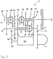
- figure 1 shows a drive train with a transmission unit 1, an internal combustion engine 2 not shown here with a clutch 3 and an output 4, which is shown here in the form of a differential.
- the transmission unit 1 includes a manual transmission 10 and an electric machine 50, which is referred to as E machine in the following.
- E machine electric machine 50
- the drive train with the transmission unit 1, the internal combustion engine 2, the clutch 3 and the differential 4 can be installed in a motor vehicle, for example as a front-transverse installation.
- the gearbox 10 has an input shaft 11 and an output shaft 12 arranged parallel thereto.
- the input shaft 11 When the clutch 3 is closed, the input shaft 11 is connected to the internal combustion engine 2 in a torque-proof manner.
- the input shaft 11 can be separated from the internal combustion engine 2 by opening the clutch 3 .
- the output shaft 12 has an output pinion 13 which is in meshing engagement with the differential 4 or, more precisely, with a housing of the differential 4 .
- the manual transmission 10 has a loose gear set designated 14 .
- the idler wheel package 14 includes a first input shaft idler wheel 15 and a second input shaft idler wheel 16 .
- the second input shaft idler wheel 16 has a first gear wheel 17 and a second gear wheel 18 .
- the diameter of the first gear wheel 17 is smaller than the diameter of the second gear wheel 18.
- a double-speed clutch 19 is provided for the non-rotatable connection of the first input shaft idler wheel 15 and the second input shaft idler wheel 16.
- the first input shaft loose wheel 15 is rotatably connected to the input shaft 11.
- the second input shaft idler wheel 16 can be connected to the input shaft 11 in a torque-proof manner via a second or right active position of the double-speed clutch 19 .
- the idler wheel package 14 also includes a first output shaft idler wheel 20 and a second output shaft idler wheel 21 which has a first gear wheel 22 and a second gear wheel 23 .
- the second gear of the second output shaft idler gear 21 is smaller than the first gear 22.
- a second double-speed clutch 24 of the idler gear set 14 serves to connect the first output shaft idler gear 20 and the second output shaft idler gear 21 to the output shaft 12 in a torque-proof manner. In a first or left active position, the second output shaft idler gear 22 is connected in a torque-proof manner to the output shaft 12, in a second active position the first output shaft idler gear 20 is connected.
- the first input shaft idler gear 15 is in direct meshing engagement with the first gear of the second output shaft idler gear 21. There is also a direct meshing engagement between the first output shaft idler gear 20 and the second gear of the second input shaft idler gear 16 given. There is another direct meshing engagement within the idler gear packet, namely between the second gear 18 of the second input shaft idler gear 16 and the second gear 23 of the second output shaft idler gear 21. Thus, in the idler gear packet 21 exactly three direct meshing engagements are realized.
- the electric machine 15 has a drive pinion 51 which meshes with an intermediate wheel 30 .
- the intermediate gear 30 in turn is in direct meshing engagement with the first input shaft idler gear 15.
- the manual transmission 10 also has two loose wheels 25, 26 which are arranged on the output shaft 12. Between idler gears 25 and 26 there is a further or third double-speed clutch 27. Gear-shift clutch 27 is used to connect idler gear 26 (left active position) or idler gear 25 (right active position) to output shaft 12 in a torque-proof manner. Two fixed wheels 28 , 29 are arranged on the input shaft 10 , the fixed wheel 28 meshing with the idler wheel 26 and the fixed wheel 29 with the idler wheel 25 .
- the first gearshift clutch 19 is moved into the left active position and the second double-speed clutch 24 is moved into the right active position.
- a torque flow takes place via the input shaft 11 and the first input shaft idler wheel 15 to the first gear wheel 22 of the second output shaft idler wheel 21.
- the torque flow is passed on via the second gear wheel 23 to the second gear wheel 18 of the second Input shaft loose wheel 16, which sits loosely on the input shaft 11 due to the left active position of the first double-speed clutch 19 in the direction of rotation.
- the first output shaft idler wheel 20 is driven via the first gear wheel 17 , which is non-rotatably connected to the output shaft 12 and thus to the output 4 due to the active position of the second double-speed clutch 24 on the right.
- the number I on the first double-speed clutch 19 and on the second double-speed clutch 24 is intended to indicate the respective active position mark that is necessary so that the first grade I or the first gear I in the manual transmission 10 is engaged.
- a second gear stage II, a fourth gear stage IV and a sixth gear stage VI can be realized via the idler wheel package 14 .
- the gear stage VI when the gear stage VI is engaged, the first double-speed clutch 19 is in the active position on the right and the second double-speed clutch 24 is in the active position on the left.
- gear III With the third double-speed clutch 27, a third gear III and a fifth gear V can be inserted.
- gear III When gear III is engaged, for example, the torque flows from the internal combustion engine 2 via the closed clutch 3 and via the input shaft 11 to the fixed wheel 28, which is in direct meshing engagement with the idler wheel 26.
- the torque flow is passed on to the abrasion 4 via the loose wheel 26, the double-speed clutch 27, the output shaft 12 with the output pinion 13.
- the electric machine 50 can be used as a booster, that is to say it can support the internal combustion engine 2 . If, for example, the first gear I is engaged and the internal combustion engine 2 and the electric machine are running in parallel, an electromotive drive power and the power of the internal combustion engine 2 are fed into the idler gear set 14 at the same time. A parallel drive of internal combustion engine 2 and electric machine 50 is possible in all gears I to VI.
- the invention makes it possible for the internal combustion engine 2 and the electric machine 50 to be connected to one another and for the output shaft 12 to be decoupled therefrom. Only the first double-speed clutch 19 is in the left or right active position (the second double-speed clutch 24 and the third double-speed clutch 27 are each in the neutral position shown here). This enables the engine 2 to be started by the electric machine 50 while the output 4 and thus the vehicle are stationary. It is also possible that when the vehicle is stationary, the internal combustion engine 2 drives the electric machine 50 in order to Charge the battery of the motor vehicle.
- the electric machine 50 can thus be used as an electric motor or as an electric generator.
- Another advantage of the invention is that when changing gear from one gear to another gear, the electric machine 50 can fill a torque gap.
- the electric machine 50 can deliver drive power, which is conducted to the output shaft 12 via the gear train 51 , 25 , 15 , 23 , 18 , 17 , 20 . It is always possible to fill the torque gap during the shifting process when shifting from one gear to the next higher gear.
- the torque gap can also be filled during further shifting processes (e.g. from I to III).
- figure 2 shows a further embodiment of the invention, wherein components that are similar or identical to the components of the embodiment of FIG figure 1 are provided with the same reference numerals. Accordingly, the explanations figure 1 referred.
- a difference from the embodiment of figure 1 is that the electric machine 50 is not connected to the manual transmission 10 via the first input shaft idler wheel 15 but via the second output shaft idler wheel 21 .
- the output pinion 51 of the E machine 50 meshes with a stepped intermediate gear 30 that has a larger gear 31 and a smaller gear 32 .
- the larger gear 31 is in direct meshing engagement with the output pinion 51, while the smaller gear 32 meshes directly with a third gear 33 of the second idler gear 21 of the output shaft.
- the third gear wheel 33 also meshes with a loose wheel 34, which is mounted on the input shaft 11 is arranged.
- another loose wheel 35 is arranged on the input shaft 11 .
- the idler gear 34 or the idler gear 35 can be connected to the input shaft 11 in a rotationally fixed manner via a third double-gear shifting clutch, now designated 36 here.
- the electric machine 50 can be connected via any idler gear of the idler gear set (for example alternatively via the second input shaft idler gear 16 or the first output shaft idler gear 20).
- Another possibility in the embodiment of figure 2 consists in using the loose wheel 34 to connect the electric machine 50 .
- Six grades I to VI can also be realized with this exemplary embodiment. If, for example, the fourth gear IV is engaged, the first double-speed clutch 19 is in position in figure 2 shown neutral position, the second double-speed clutch 24 in the left active position and the third double-speed clutch 36 in the right active position. The torque flow from the internal combustion engine 2 takes place via the idler wheel 34 to the second output shaft idler wheel 21 , which is connected to the output shaft 12 in a torque-proof manner via the second double-speed clutch 24 .
- a separating device can be provided between the electric machine 50 and the respective idler wheel, via which the electric machine 50 is connected to the manual transmission 10, in order to temporarily decouple the electric machine 50 from the idler gear set 14 .
- the exemplary embodiments figures 1 and 2 do not have a mechanical reverse gear. Reversing of the motor vehicle would basically be possible by the electric machine 50 (for example by reverse running of the electric machine 50 and with the right active position of the second double-speed clutch 24). But it is also possible, the embodiments of figure 1 and 2 equipped with an additional mechanical reverse gear, but this is not shown here.
Landscapes
- Engineering & Computer Science (AREA)
- Mechanical Engineering (AREA)
- Chemical & Material Sciences (AREA)
- Combustion & Propulsion (AREA)
- Transportation (AREA)
- General Engineering & Computer Science (AREA)
- Hybrid Electric Vehicles (AREA)
- Structure Of Transmissions (AREA)
Description
- Die Erfindung betrifft eine Getriebeeinheit für ein Kraftfahrzeug, wobei die Getriebeeinheit ein Schaltgetriebe und eine elektrische Maschine (E-Maschine) umfasst. Das Schaltgetriebe weist eine einzige Eingangswelle auf, die mit einem Hauptantrieb des Kraftfahrzeugs gekoppelt werden kann. Des Weiteren weist das Schaltgetriebe eine einzige Ausgangswelle auf, die mit einem Abtrieb des Kraftfahrzeugs gekoppelt werden kann. Die Erfindung betrifft auch eine Antriebseinheit, die die Getriebeeinheit und den Hauptantrieb umfasst.
- Aus der
DE 10 2012 024 677 A1 ist eine derartige Getriebeeinheit bekannt. Den Hauptantrieb stellt ein Verbrennungsmotor des Kraftfahrtzeugs dar, der in einem Ausführungsbeispiel über eine Anfahr- und Trennkupplung mit der Eingangswelle verbunden ist. Der Abtrieb wird gebildet durch ein Differential, dessen Gehäuse mit einem Festrad auf der Ausgangswelle kämmt. - Die Anbindung der E-Maschine an das Schaltgetriebe erfolgt über zwei unterschiedlich große Losräder, die auf der Ausgangswelle des Schaltgetriebes angeordnet sind und über eine Doppelgangschaltkupplung wahlweise mit der Ausgangswelle drehfest verbunden werden können. Die Losräder kämmen mit jeweils mit einer der Zahnrädern eines gestuften Antriebsritzel der E-Maschine, sodass zwei elektrische Gangstufen realisiert werden können. Zur Realisierung von verbrennungsmotoischen Gangstufen weist das Schaltgetriebe weitere Losräder und weitere Doppelgangschaltkupplungen auf, die ebenfalls alle auf der Ausgangswelle angeordnet sind.
- Bei der Konstruktion und Auslegung der Getriebeeinheit mit Schaltgetriebe und E-Maschine müssen nicht nur Vorgaben wie beispielsweise Leistung, Anzahl der Gänge, minimale und maximale Übersetzung etc., sondern auch Vorgaben hinsichtlich Kosten und des Raumangebots (Packaging) im Motorraum des Kraftfahrzeugs berücksichtigt bzw. eingehalten werden. Dies kann im Einzelfall dazu führen, dass eine eigentlich favorisierte Getriebeeinheit nicht alle Vorgaben erfüllt und daher als mögliche Variante ausfällt.
- Die
DE 10 2011 088 592 A1 offenbart eine Getriebeeinheit mit einem Doppelkupplungsgetriebe und einer E-Maschine. Das Doppelkupplungsgetriebe weist zwei koaxiale Eingangswellen in Form einer Hohlwelle und einer Innenwelle, zwei Vorgelegewellen und eine Ausgangswelle auf. Die Anbindung der E-Maschine an das Doppelkupplungsgetriebe erfolgt über ein auf der Innenwelle angeordnetes Losrad mit zwei axial beabstandeten Zahnrädern, die mit Losrädern kämmen, die auf einer der Vorgelegewellen sitzen. Auf der Ausgangswelle sind lediglich Festräder angeordnet, von denen eins in einer Radabtriebsebene gleichzeitig mit zwei Festrädern kämmt, die jeweils einer der Vorgelegewellen zugeordnet sind. - Die
EP 1 467 123 A1 offenbart eine Getriebeeinheit mit einem Schaltgetriebe, das eine einzelne Eingangswelle und eine einzelne Ausgangswelle umfasst, auf welchen jeweils Losräder angeordnet sind, die jeweils drei durch eine Hohlwelle fest verbundene Zahnräder aufweisen. - Der Erfindung liegt daher die Aufgabe zu Grunde, eine weitere, ein Schaltgetriebe und eine E-Maschine umfassende Getriebeeinheit bereit zu stellen, die kompakt und einfach aufgebaut ist und eine Vielzahl von Gangstufen aufweist.
- Die der Erfindung zu Grunde liegende Aufgabe wird mit der Getriebeeinheit gemäß Anspruch 1 gelöst. Ausführungsbeispiele der Erfindung können den Unteransprüchen zu Anspruch 1 entnommen werden.
- Erfindungsgemäß ist vorgesehen, dass die Anbindung der E-Maschine an das Schaltgetriebe über ein Losradpaket erfolgt, dass ein auf der Eingangswelle angeordnetes erstes Eingangswellen-Losrad, ein zweites Eingangswellen-Losrad, welches ein erstes Zahnrad und ein im Durchmesser unterschiedlich großes zweites Zahnrad aufweist, und eine erste Doppelgangschaltkupplung umfasst. Durch die erste Doppelgangschaltkupplung sind in einer ersten Aktivstellung der Doppelgangschaltkupplung das erste Eingangswellen-Losrad mit der Eingangswelle und in einer zweiten Aktivstellung das zweite Eingangswellen-Losrad mit der Eingangswelle drehfest verbindbar. Des Weiteren umfasst das Losradpaket ein auf der Ausgangswelle angeordnetes erstes Ausgangswellen-Losrad, ein zweites Ausgangswellen-Losrad, welches ein erstes Zahnrad und ein im Durchmesser unterschiedlich großes zweites Zahnrad aufweist, und eine zweite Doppelgangschaltkupplung. Die zweite Doppelgangschaltkupplung dient dazu, in einer ersten Aktivstellung das zweite Ausgangswellen-Losrad mit der Ausgangswelle und in einer zweiten Aktivstellung das erste Ausgangswellen-Losrad mit der Ausgangswelle drehfest zu verbinden. Erfindungsgemäß kämmt das erste Eingangswellen-Losrad unmittelbar mit dem ersten Zahnrad des zweiten Ausgangswellen-Losrades, während das erste Ausgangswellen-Losrad mit dem ersten Zahnrad des zweiten Eingangswellen-Losrades unmittelbar kämmt. Zudem steht das zweite Zahnrad des zweiten Eingangswellen-Losrades mit dem zweiten Zahnrad des zweiten Ausgangswellen-Losrades in unmittelbaren kämmenden Eingriff.
- Der unmittelbare kämmende Eingriff zwischen zwei Zahnrädern bedeutet, dass kein weiteres Zahnrad oder kein weiteres Bauteil zwischen diesen beiden Zahnrädern geschaltet ist. Entsprechend greifen die Verzahnungen der beiden zwei Zahnräder unmittelbar ineinander.
- In einem Ausführungsbeispiel erfolgt die Anbindung der E-Maschine über das erste Eingangswellen-Losrad. Alternativ kann die Anbindung der E-Maschine auch über das erste Zahnrad des zweiten Ausgangswellen-Losrad erfolgen. Durch eine derartige Anbindung der E-Maschine wird eine elektromotorische Antriebsleistung der E-Maschine auf das betreffende Losrad übertragen und somit in das Lospaket übertragen. Über eine der Doppelgangschaltkupplung des Losradpakets oder durch die beiden Doppelgangschaltkupplungen des Losradpakets kann diese elektromotorische Antriebsleistung auf die Eingangswelle, die Ausgangswelle oder auf beide Wellen geleitet werden. Beispielsweise kann durch die E-Maschine ein Verbrennungsmotor gestartet werden, der an der Eingangswelle beispielsweise über eine Reibkupplung angekoppelt ist. Dazu befindet sich die erste Doppelgangschaltkupplung in einer ihrer Aktivstellungen, so dass die E-Maschine den Verbrennungsmotor über die Eingangswelle starten kann. Die zweite, auf der Ausgangswelle sitzende Doppelgangschaltkupplung des Losradpakets ist dabei vorzugsweise geöffnet, so dass der Abtrieb von dem Startvorgang entkoppelt ist. Auch ließe sich bei geöffneter zweiter Doppelgangschaltkupplung der Verbrennungsmotor als Generator zur Stromerzeugung nutzen. Die E-Maschine kann im Sinne der Erfindung motorisch oder zur Stromerzeugung bzw. zum Aufladen einer Batterie genutzt werden.
- Die E-Maschine kann ein Antriebsritzel aufweisen, dass mit einem der Losräder des Losradpakets unmittelbar oder über ein Zwischenrad in kämmenden Eingriff steht. Erfolgt die Anbindung der E-Maschine beispielsweise über das erste Eingangswellen-Losrad, so steht dieses erste Eingangswellen-Losrad sowohl mit dem ersten Zahnrad des zweiten Ausgangswellen-Losrads als auch mit Antriebsritzel in unmittelbaren kämmenden Eingriff. Ist ein Zwischenrad vorgesehen, kämmt das Zwischenrad unmittelbar mit dem zweiten Ausgangswellen-Losrad.
- Durch das Losradpaket lassen sich mehrere Gangstufen im Schaltgetriebe realisieren. Dabei kann über jede dieser Gangstufen die elektromotorische Leistung oder auch die Leistung des Hauptantriebs über die Eingangswelle und die Ausgangswelle zum Abtrieb geleitet werden. Auch ist es möglich, die E-Maschine als Booster zu verwenden. Im letztgenannten Fall werden in das Losradpaket gleichzeitig die elektromotorische Leistung und die Leistung des Hauptantriebs eingespeist.
- Das zweite Ausgangswellen-Losrad kann ein drittes Zahnrad aufweisen, über das die Anbindung der E-Maschine in das Losradpaket erfolgt.
- Das Zwischenrad, das zwischen Antriebsritzel der E-Maschine und einem der Losräder des Losradpakets geschaltet sein kann, kann als gestuftes Zahnrad mit einem kleineren Zahnrad und einem größeren Zahnrad ausgebildet sein. Dabei kann das größere Zahnrad im unmittelbaren kämmenden Eingriff mit dem Antriebsritzel der E-Maschine stehen. Das kleinere Zahnrad des Zwischenrads kämmt in diesem Fall unmittelbar mit dem ersten Eingangswellen-Losrad bzw. mit einem Zahnrad des zweiten Ausgangswellen-Losrads.
- Die erste Doppelgangschaltkupplung der Eingangswelle kann axial zwischen dem ersten Zahnrad und dem zweiten Zahnrad des zweiten Ausgangswellen - Losrads angeordnet sein. Zusätzlich oder alternativ kann die zweite Doppelgangschaltkupplung auf axial zwischen dem ersten Zahnrad und dem zweiten Zahnrad des zweiten Eingangswellen-Losrad angeordnet sein.
- In einem Ausführungsbeispiel kommt es in radialer Richtung gesehen, also in Richtung einer Verbindungslinie zwischen Eingangswellen und Ausgangswelle, zu einer Überschneidung der ersten Doppelgangschaltkupplung mit wenigstens einem der Zahnräder des zweiten Ausgangswellen-Losrads. Dies bedeutet, dass ein äußerer Durchmesser der ersten Doppelgangschaltkupplung der Eingangswellen und ein Außendurchmesser des größten Zahnrads des zweiten Ausgangswellen-Losrads in Summe größer sind als ein Achsabstand zwischen Eingangwelle und Ausgangswelle. Auch ein äußerer Durchmesser der zweiten Doppelgangschaltkupplung auf der Ausgangswelle und ein Außendurchmesser des größten Zahnrads des zweiten Eingangswellen-Losrads kann größer sein als der Achsabstand zwischen Eingangswelle und Ausgangswelle.
- In einem Ausführungsbeispiel umfasst das Schaltgetriebe wenigstens eine dritte Doppelgangschaltkupplung, durch die zwei weitere Losräder, die auf der Ausgangswelle angeordnet sind, drehfest mit der Ausgangswelle verbunden werden können. In diesem Ausführungsbeispiel sind zwei Festräder auf der Eingangswellen angeordnet, die mit den Losrädern auf der Ausgangswelle in Eingriff stehen. Dadurch kann die Anzahl der Gangstufen des Schaltgetriebes erhöht werden.
- In einem alternativen Ausführungsbeispiel sorgt die dritte Doppelgangschaltkupplung dafür, dass die zwei weiteren Losräder, die nun auf der Eingangswelle angeordnet sind, drehfest mit der Eingangswelle verbunden werden können. Entsprechend sind in diesem Ausführungsbeispiel zusätzliche Festräder auf der Ausgangswelle vorzusehen.
- Eines der zwei weiteren Losräder auf der Eingangswellen kann mit dem dritten Zahnrad des zweiten Ausgangswellen Losrad unmittelbar im kämmenden Eingriff stehen. Dies sorgt für ein kompaktes Schaltgetriebe mit vielen möglichen Gangstufen.
- Erfindungsgemäß weist das Schaltgetriebe keine weitere Eingangswelle auf. Es handelt sich somit nicht um ein Doppelkupplungsgetriebe, das zwei Eingangswellen aufweist. Erfindungsgemäß weist das Schaltgetriebe nur eine einzige Eingangswelle auf. Auch handelt es sich nicht um ein lastverzweigendes Getriebe, bei dem die Leistung des Hauptantriebs von der Eingangswelle auf zwei Ausgangswellen verzweigt wird. Erfindungsgemäß weist das Schaltgetriebe nur eine einzige Eingangswelle und nur eine einzige Ausgangswelle auf.
- Eine weitere Aufgabe der Erfindung, die Bereitstellung einer die Getriebeeinheit und den Hauptantrieb umfassenden Antriebseinheit, wird mit Anspruch 11 gelöst. Ein Ausführungsbeispiel für die Antriebseinheit beschreibt Anspruch 12.
- Bei der erfindungsgemäßen Antriebseinheit ist der Hauptantrieb mit der Eingangswelle des Schaltgetriebes der Getriebeeinheit gekoppelt. In einem Ausführungsbeispiel ist zwischen dem Hauptantrieb und der Eingangswelle eine Kupplung vorgesehen, die beispielsweise als Reibkupplung oder als einfache Trennkupplung ausgestaltet sein kann. Es ist auch möglich, keine Kupplung zwischen Eingangswelle des Schaltgetriebes und dem Hauptantrieb, welcher beispielsweise ein Verbrennungsmotor sein kann, vorzusehen. In diesem Fall kann eine drehfeste Verbindung zwischen Eingangswelle und Hauptantrieb bestehen.
- Anhand der in den Figuren dargestellten Ausführungsbeispiele wird die Erfindung näher erläutert. Es zeigen:
- Figur 1
- schematisch ein erstes Ausführungsbeispiel der Erfindung; und
- Figur 2
- schematisch zweites Ausführungsbeispiel der Erfindung.
-
Figur 1 zeigt einen Antriebsstrang mit einer Getriebeeinheit 1, einen hier nicht weiter dargestellten Verbrennungsmotor 2 mit einer Kupplung 3 sowie einen Abtrieb 4, der hier in Form eines Differenzials abgebildet ist. Die Getriebeeinheit 1 umfasst ein Schaltgetriebe 10 und eine elektrische Maschine 50, die im Folgenden als E Maschine bezeichnet wird. Der Antriebsstrang mit der Getriebeeinheit 1, den Verbrennungsmotor 2, der Kupplung 3 und dem Differenzial 4 kann in einem Kraftfahrzeug eingebaut werden, beispielsweise als Front-Quer-Einbau. - Das Schaltgetriebe 10 weist eine Eingangswelle 11 und eine dazu parallel angeordnete Ausgangswelle 12 auf. Bei geschlossener Kupplung 3 ist die Eingangswelle 11 drehfest mit dem Verbrennungsmotor 2 verbunden. Durch Öffnen der Kupplung 3 lässt sich die Eingangswelle 11 von dem Verbrennungsmotor 2 trennen. Die Ausgangswelle 12 weist einen Abtriebsritzel 13 auf, das mit dem Differenzial 4 oder genauer gesagt mit einem Gehäuse des Differenzials 4 im kämmenden Eingriff steht.
- Das Schaltgetriebe 10 weist ein mit 14 bezeichnetes Losradpaket auf. Das Losradpaket 14 umfasst ein erstes Eingangswellen-Losrad 15 und ein zweites Eingangswellen-Losrad 16. Das zweite Eingangswellen-Losrad 16 weist ein erstes Zahnrad 17 und ein zweites Zahnrad 18 auf. Der Durchmesser des ersten Zahnrads 17 ist dabei kleiner als der Durchmesser des zweiten Zahnrads 18. Zur drehfesten Verbindung des ersten Eingangswellen-Losrads 15 und des zweiten Eingangswellen-Losrad 16 ist eine Doppelgangschaltkupplung 19 vorgesehen. In einer ersten oder in der Darstellung der
Figur 1 linken Aktivstellung der Doppelgangschaltkupplung 19 ist das erste Eingangswellen-Losrad 15 drehfest mit der Eingangswelle 11 verbunden. Über eine zweite oder rechte Aktivstellung der Doppelgangschaltkupplung 19 lässt sich das zweite Eingangswellen-Losrad 16 drehfest mit der Eingangswelle 11 verbinden. - Das Losradpaket 14 umfasst des Weiteren ein erstes Ausgangswellen-Losrad 20 und ein zweites Ausgangswellen-Losrad 21, welches ein erstes Zahnrad 22 und ein zweites Zahnrad 23 aufweist. Das zweite Zahnrad des zweiten Ausgangswellen-Losrads 21 ist dabei kleiner als das erste Zahnrad 22. Eine zweite Doppelgangschaltkupplung 24 des Losradpakets 14 dient dazu, das erste Ausgangswellen-Losrad 20 bzw. das zweite Ausgangswellen-Losrad 21 drehfest mit der Ausgangswelle 12 zu verbinden. In einer ersten oder linken Aktivstellung ist das zweite Ausgangswellen-Losrad 22, in einer zweiten Aktivstellung ist das erste Ausgangswellen Losrad 20 drehfest mit der Ausgangswelle 12 verbunden.
- Das erste Eingangswellen-Losrad 15 steht im unmittelbaren kämmenden Eingriff mit dem ersten Zahnrad des zweiten Ausgangswellen-Losrads 21. Ebenso ist ein unmittelbarer kämmenden Eingriff zwischen dem ersten Ausgangswellen-Losrad 20 und dem zweiten Zahnrad des zweiten Eingangswellen-Losrad 16 gegeben. Innerhalb des Losradpakets gibt es noch einen weiteren unmittelbaren kämmenden Eingriff, nämlich zwischen dem zweiten Zahnrad 18 des zweiten Eingangswellen-Losrads 16 und dem zweiten Zahnrad 23 des zweiten Ausgangswellen-Losrads 21. Somit sind in dem Losradpaket 21 genau drei unmittelbare kämmen de Eingriffe realisiert.
- Die E-Maschine 15 weist ein Antriebsritzel 51 auf, das mit einem Zwischenrad 30 kämmt. Das Zwischenrad 30 wiederum steht im unmittelbaren kämmenden Eingriff mit dem ersten Eingangswellen-Losrad 15.
- Das Schaltgetriebe 10 weist des Weiteren zwei Losräder 25, 26 auf, die auf der Ausgangswelle 12 angeordnet sind. Zwischen den Losrädern 25 und 26 befindet sich eine weitere oder dritte Doppelgangschaltkupplung 27. Die Gangschaltkupplung 27 dient dazu, das Losrad 26 (linke Aktivstellung) oder das Losrad 25 (rechte Aktivstellung) drehfest mit der Ausgangswelle 12 zu verbinden. Auf der Eingangswelle 10 sind zwei Festräder 28, 29 angeordnet, wobei das Festrad 28 mit dem Losrad 26 und das Festrad 29 mit dem Losrad 25 kämmen.
- Zum Einlegen einer ersten Gangstufe I werden die erste Gangschaltkupplung 19 in die linke Aktivstellung und die zweite Doppelgangschaltkupplung 24 in die rechte Aktivstellung bewegt. Bei einem Antrieb durch den Verbrennungsmotor 2 erfolgt somit ein Drehmomentfluss über die Eingangswelle 11 und das erste Eingangswellen-Losrad 15 auf das erste Zahnrad 22 des zweiten Ausgangswellen- Losrads 21. Der Drehmomentfluss wird weitergeführt über das zweite Zahnrad 23 auf das zweite Zahnrad 18 des zweiten Eingangswellen-Losrads 16, das aufgrund der linken Aktivstellung der ersten Doppelgangschaltkupplung 19 in Drehrichtung lose auf der Eingangswelle 11 sitzt. Über das erste Zahnrad 17 wird das erste Ausgangswellen-Losrad 20 angetrieben, welches aufgrund der rechten Aktivstellung der zweiten Doppelgangschaltkupplung 24 drehfest mit der Ausgangswelle 12 und somit dem Abtrieb 4 verbunden ist. Die Ziffer I an der ersten Doppelgangschaltkupplung 19 und an der zweiten Doppelgangschaltkupplung 24 soll die jeweilige Aktivstellung kennzeichnen, die notwendig ist, damit die erste Gangstufe I bzw. der erste Gang I im Schaltgetriebe 10 eingelegt ist.
- Über das Losradpaket 14 lassen sich zudem eine zweite Gangstufe II, eine vierte Gangstufe IV und eine sechste Gangstufe VI realisieren. Bei beispielsweise eingelegter Gangstufe VI befinden sich die erste Doppelgangschaltkupplung 19 in der rechten Aktivstellung und die zweite Doppelgangschaltkupplung 24 in der linken Aktivstellung.
- Mit der dritten Doppelgangschaltkupplung 27 lassen sich eine dritte Gangstufe III und eine fünfte Gangstufe V einlegen. Bei eingelegter Gangstufe III beispielsweise erfolgt der Drehmomentfluss von dem Verbrennungsmotor 2 über die geschlossene Kupplung 3 und über die Eingangswelle 11 auf das Festrad 28, das mit dem Losrad 26 im unmittelbaren kämmenden Eingriff steht. Der Drehmomentfluss wird über das Losrad 26, die Doppelgangschaltkupplung 27, die Ausgangswelle 12 mit dem Abtriebsritzel 13 auf den Abrieb 4 weitergeleitet.
- Die E-Maschine 50 kann als Booster eingesetzt werde, also den Verbrennungsmotor 2 unterstützen. Ist beispielsweise die erste Gangstufe I eingelegt und laufen der Verbrennungsmotor 2 und die E-Maschine parallel, so wird gleichzeitig eine elektromotorische Antriebsleistung und die Leistung des Verbrennungsmotors 2 in das Losradpaket 14 eingespeist. In allen Gangstufen I bis VI ist ein Parallelantrieb von Verbrennungsmotor 2 und E-Maschine 50 möglich.
- Zudem ist durch die Erfindung möglich, dass der Verbrennungsmotor 2 und die E-Maschine 50 miteinander verbunden sein können und dass sich die Ausgangswelle 12 davon entkoppelt ist. Dabei befindet sich lediglich die erste Doppelgangschaltkupplung 19 in der linken oder rechten Aktivstellung (die zweite Doppelgangschaltkupplung 24 und die dritte Doppelgangschaltkupplung 27 befinden sich jeweils in der hier dargestellten Neutralstellung). Dadurch ist ein Anlassen des Motors 2 durch die E-Maschine 50 möglich, während der Abtrieb 4 und somit das Fahrzeug stillsteht. Auch ist es so möglich, dass bei stillstehendem Fahrzeug der Verbrennungsmotor 2 die E-Maschine 50 antreibt, um somit eine Batterie des Kraftfahrzeugs aufzuladen. Die E-Maschine 50 kann somit als elektrischer Motor oder als elektrischer Generator zum Einsatz kommen.
- Ein weiterer Vorteil der Erfindung besteht darin, dass bei einem Gangwechsel von einer Gangstufe in eine andere Gangstufe die E-Maschine 50 eine Drehmomentlücke füllen kann. Soll beispielsweise das Schaltgetriebe 10 von der ersten Gangstufe I in die zweite Gangstufe II geschaltet werden, so muss die erste Doppelgangschaltkupplung 19 von der linken Aktivstellung in die rechte Aktivstellung bewegt werden. Während diesem Schaltvorgang kann die E-Maschine 50 eine Antriebsleistung liefern, die über die Zahnradfolge 51, 25, 15, 23, 18, 17, 20 auf die Ausgangswelle 12 geleitet wird. Das füllen der Drehmomentlücke beim Schaltvorgang ist immer möglich, wenn von einer Gangstufe auf die nächst höhere Gangstufe geschaltet wird. Darüber hinaus ist ein Auffüllen der Drehmomentlücke auch bei weiteren Schaltvorgängen (beispielsweise von I auf III) möglich.
- Bei eingelegter dritter Gangstufe III erfolgt ein Gangwechsel für die E-Maschine 50. Bei diesem Gangwechsel wird die zweite Doppelgangschaltkupplung 24 von der rechten Aktivstellung in die linke Aktivstellung verschoben.
-
Figur 2 zeigt ein weiteres Ausführungsbeispiel der Erfindung, wobei Bauteile, die ähnlich oder identisch zu den Bauteilen des Ausführungsbeispiels derFigur 1 sind, mit gleichen Bezugszeichen versehen sind. Entsprechend wird auf die Ausführungen zuFigur 1 verwiesen. - Ein Unterschied zum Ausführungsbeispiel der
Figur 1 besteht darin, dass die E-Maschine 50 nicht über das erste Eingangswellen-Losrad 15, sondern über das zweite Ausgangswellen-Losrad 21 an das Schaltgetriebe 10 angebunden ist. Das Abtriebsritzel 51 der E Maschine 50 kämmt mit einem gestuften Zwischenrad 30, dass ein größeres Zahnrad 31 und ein kleineres Zahnrad 32 aufweist. Das größere Zahnrad 31 steht im unmittelbaren kämmenden Eingriff mit dem Abtriebsritzel 51, während das kleinere Zahnrad 32 unmittelbar mit einem dritten Zahnrad 33 des zweiten Ausgangswellen-Losrads 21 kämmt. Das dritte Zahnrad 33 kämmt des Weiteren mit einem Losrad 34, welches auf der Eingangswelle 11 angeordnet ist. Darüber hinaus ist auf der Eingangswelle 11 ein weiteres Losrad 35 angeordnet. Über eine hier nun mit 36 bezeichnete dritte Doppelgangschaltkupplung lässt sich das Losrad 34 bzw. das Losrad 35 drehfest mit der Eingangswellen 11 verbinden. - Es sei an dieser Stelle betont, dass die Anbindung der E-Maschine 50 über ein beliebiges Losrad des Losradspakets erfolgen kann (beispielsweise alternativ über das zweite Eingangswellen-Losrad 16 oder das erste Ausgangswellen-Losrad 20). Eine andere Möglichkeit im Ausführungsbeispiel der
Figur 2 besteht darin, dass Losrad 34 zur Anbindung der E-Maschine 50 zu verwenden. - Mit diesem Ausführungsbeispiel lassen sich ebenfalls sechs Gangstufen I bis VI realisieren. Ist beispielsweise die vierte Gangstufe IV eingelegt, so befindet sich die erste Doppelgangschaltkupplung 19 in der in
Figur 2 dargestellten Neutralstellung, die zweite Doppelgangschaltkupplung 24 in der linken Aktivstellung und die dritte Doppelgangschaltkupplung 36 in der rechten Aktivstellung. Der Drehmomentfluss von dem Verbrennungsmotor 2 erfolgte dabei über das Losrad 34 auf das zweite Ausgangswellen-Losrad 21, das über die zweite Doppelgangschaltkupplung 24 drehfest mit der Ausgangswelle 12 verbunden ist. - Es sei darauf hingewiesen, dass zwischen der E-Maschine 50 und dem jeweiligen Losrad, über das die E-Maschine 50 an das Schaltgetriebe 10 angebunden ist, eine Trennvorrichtung vorgesehen sein kann, um die E-Maschine 50 von dem Losradpaket 14 zeitweise zu entkoppeln.
- Die Ausführungsbeispiele der
Figuren 1 und2 weisen keinen mechanischen Rückwärtsgang auf. Ein Rückwärtsfahren des Kraftfahrzeugs wäre grundsätzlich durch die E-Maschine 50 möglich (beispielsweise durch einen Rückwärtslauf der E-Maschine 50 und bei rechte Aktivstellung der zweiten Doppelgangschaltkupplung 24). Es ist aber auch möglich, die Ausführungsbeispiele derFigur 1 und2 mit einem zusätzlichen mechanischen Rückwärtsgang auszustatten, was aber hier nicht dargestellt ist. -
- 1
- Getriebeeinheit
- 2
- Verbrennungsmotor
- 3
- Kupplung
- 4
- Differenzial
- 10
- Schaltgetriebe
- 11
- Eingangswelle
- 12
- Ausgangswelle
- 13
- Abtriebsritzel
- 14
- Losradpaket
- 15
- Erstes Eingangswellen-Losrad
- 16
- Zweites Eingangswellen-Losrad
- 17
- Erstes Zahnrad
- 18
- Zweites Zahnrad
- 19
- Erste Doppelgangschaltkupplung
- 20
- Erstes Ausgangswellen-Losrad
- 21
- Zweites Ausgangswellen-Losrad
- 22
- Erstes Zahnrad
- 23
- Zweites Zahnrad
- 24
- Zweite Doppelgangschaltkupplung
- 25
- Losrad
- 26
- Losrad
- 27
- Dritte Doppelgangschaltkupplung
- 28
- Festrad
- 29
- Festrad
- 30
- Zwischenrad
- 31
- Größeres Zahnrad
- 32
- Kleineres Zahnrad
- 33
- Drittes Zahnrad
- 34
- Losrad
- 35
- Losrad
- 36
- Dritte Doppelgangschaltkupplung
Claims (12)
- Getriebeeinheit (1) für ein Kraftfahrzeug, mit einem Schaltgetriebe (10) und einer E-Maschine (50), wobei das Schaltgetriebe (10) eine einzige, mit einem Hauptantrieb des Kraftfahrzeugs koppelbare Eingangswelle (11) und eine einzige, mit einem Abtrieb des Kraftfahrzeugs koppelbare Ausgangswelle (12) umfasst, wobei die Anbindung der E-Maschine (50) an das Schaltgetriebe (10) über ein Losradpaket (14) erfolgt, das umfasst:- ein auf der Eingangswelle (11) angeordnetes erstes Eingangswellen-Losrad (15), ein zweites Eingangswellen-Losrad (16), welches ein erstes Zahnrad (17) und ein im Durchmesser unterschiedlich großes zweites Zahnrad (18) aufweist, und eine erste Doppelgangschaltkupplung (19), durch die in einer ersten Aktivstellung das erste Eingangswellen-Losrad (15) mit der Eingangswelle (11) und in einer zweiter Aktivstellung das zweite Eingangswellen-Losrad (16) mit der Eingangswelle (11) drehfest verbindbar sind,- eine auf der Ausgangswelle (12) angeordnetes erstes Ausgangswellen-Losrad (20), ein zweites Ausgangswellen-Losrad (21), welches ein erstes Zahnrad (22) und ein im Durchmesser unterschiedlich großes zweites Zahnrad (23) aufweist, wobei das erste Eingangswellen-Losrad (15) mit dem ersten Zahnrad (22) des zweiten Ausgangswellen-Losrades (21) unmittelbar kämmt, das erste Ausgangswellen-Losrad (20) mit dem ersten Zahnrad (17) des zweiten Eingangswellen-Losrades (16) unmittelbar kämmt, und wobei das zweite Zahnrad (18) des zweiten Eingangswellen-Losrades (16) mit dem zweiten Zahnrad (23) des zweiten Ausgangswellen-Losrades (21) unmittelbar kämmt,dadurch gekennzeichnet, dass das Losradpaket (14) eine zweite Doppelgangschaltkupplung (24) umfasst, durch die in einer ersten Aktivstellung das zweite Ausgangswellen-Losrad (21) mit der Ausgangswelle (12) und in einer zweiter Aktivstellung das erste Ausgangswellen-Losrad (20) mit der Ausgangswelle (12) drehfest verbindbar sind.
- Getriebeeinheit (1) nach Anspruch 1, dadurch gekennzeichnet, dass die Anbindung der E-Maschine (50) über das erste Eingangswellen-Losrad (15) des Losradpakets (14) erfolgt.
- Getriebeeinheit (1) nach Anspruch 1, dadurch gekennzeichnet, dass die Anbindung der E-Maschine (50) über das erste Zahnrad (22) des zweiten Ausgangswellen-Losrads (21) erfolgt.
- Getriebeeinheit (1) nach Anspruch 1, dadurch gekennzeichnet, dass das zweite Ausgangswellen-Losrad (21) ein drittes Zahnrad (33) aufweist, über das die Anbindung der E-Maschine (50) in das Losradpaket (14) erfolgt.
- Getriebeeinheit (1) nach einem der Ansprüche 2 bis 4, dadurch gekennzeichnet, dass die E-Maschine (50) ein Antriebsritzel (51) aufweist, das mit einem der Losräder des Losradpakets (14) über ein Zwischenrad (30) in kämmenden Eingriff steht.
- Getriebeeinheit (1) nach Anspruch 5, dadurch gekennzeichnet, dass das Zwischenrad (30) ein gestuftes Zahnrad mit einem kleineren Zahnrad (32) und einem größeren Zahnrad (33) ist.
- Getriebeeinheit (1) nach einem der Ansprüche 1 bis 6, dadurch gekennzeichnet, dass die erste Doppelgangschaltkupplung (19) der Eingangswelle (11) axial zwischen den Zahnrädern (22, 23) des zweiten Ausgangswellen-Losrads (21) und die zweite Doppelgangschaltkupplung (24) auf der Ausgangswelle (12) axial zwischen den Zahnrädern (17, 18) des zweiten Eingangswellen-Losrads (16) angeordnet sind.
- Getriebeeinheit (1) nach einem der Ansprüche 1 bis 7, dadurch gekennzeichnet, dass das Schaltgetriebe (10) wenigstens eine dritte Doppelgangschaltkupplung (27) umfasst, durch die zwei weitere Losräder (25, 26), die auf der Ausgangswelle (12) angeordnet sind, drehfest mit der Ausgangswelle (12) verbindbar sind.
- Getriebeeinheit (1) nach einem der Ansprüche 1 bis 7, dadurch gekennzeichnet, dass das Schaltgetriebe (10) wenigstens eine dritte Doppelgangschaltkupplung (30) umfasst, die die zwei weiteren Losräder (34, 35), die auf der Eingangswelle (11) angeordnet sind, drehfest mit der Eingangswelle (11) verbindbar sind.
- Getriebeeinheit (1) nach Anspruch 4 und Anspruch 9, dadurch gekennzeichnet, dass eines der zwei weiteren Losräder (34, 35) mit dem dritten Zahnrad (33) des zweiten Ausgangswellen-Losrad (21) unmittelbar im kämmenden Eingriff steht.
- Antriebseinheit mit einer Getriebeeinheit (1) nach einem der Ansprüche 1 bis 10 und mit einem Hauptantrieb (2), wobei die Eingangswelle (11) des Schaltgetriebes der Getriebeeinheit mit dem Hauptantrieb gekoppelt ist.
- Antriebseinheit nach Anspruch 11, dadurch gekennzeichnet, dass zwischen dem Hauptantrieb (2) und der Eingangswelle (11) eine Kupplung (3) vorgesehen ist.
Applications Claiming Priority (3)
| Application Number | Priority Date | Filing Date | Title |
|---|---|---|---|
| DE102017119915 | 2017-08-30 | ||
| DE102018104334.1A DE102018104334A1 (de) | 2017-08-30 | 2018-02-26 | Getriebeeinheit mit Schaltgetriebe und E-Maschine |
| PCT/EP2018/072066 WO2019042767A1 (de) | 2017-08-30 | 2018-08-14 | Getriebeeinheit mit schaltgetriebe und e-maschine, sowie antriebseinheit |
Publications (2)
| Publication Number | Publication Date |
|---|---|
| EP3676119A1 EP3676119A1 (de) | 2020-07-08 |
| EP3676119B1 true EP3676119B1 (de) | 2022-08-03 |
Family
ID=65321510
Family Applications (1)
| Application Number | Title | Priority Date | Filing Date |
|---|---|---|---|
| EP18781962.8A Active EP3676119B1 (de) | 2017-08-30 | 2018-08-14 | Getriebeeinheit mit schaltgetriebe und e-maschine sowie antriebseinheit |
Country Status (4)
| Country | Link |
|---|---|
| EP (1) | EP3676119B1 (de) |
| CN (1) | CN111417534A (de) |
| DE (1) | DE102018104334A1 (de) |
| WO (1) | WO2019042767A1 (de) |
Families Citing this family (2)
| Publication number | Priority date | Publication date | Assignee | Title |
|---|---|---|---|---|
| CN113320376A (zh) * | 2021-07-15 | 2021-08-31 | 株洲齿轮有限责任公司 | Amt单电机混动变速器及其驱动控制方法 |
| DE102022132459B4 (de) | 2022-12-07 | 2025-03-27 | Schaeffler Technologies AG & Co. KG | Flexible mehrgängige Getriebevorrichtung für ein Kraftfahrzeug mit elektrifiziertem Antriebsstrang; sowie Antriebsstrang |
Family Cites Families (10)
| Publication number | Priority date | Publication date | Assignee | Title |
|---|---|---|---|---|
| DE10136725B4 (de) * | 2000-07-28 | 2016-09-15 | Aisin Seiki K.K. | Leistungsübertragungsvorrichtung für ein Hybridfahrzeug |
| JP2003237393A (ja) * | 2002-02-12 | 2003-08-27 | Aisin Ai Co Ltd | 動力源を備えた変速装置 |
| FR2853705B1 (fr) * | 2003-04-09 | 2006-03-24 | Renault Sa | Boite de vitesses pour vehicule automobile |
| CN102259583B (zh) * | 2010-05-31 | 2014-03-19 | 比亚迪股份有限公司 | 混合动力驱动系统及具有该系统的车辆 |
| DE102010052746B4 (de) * | 2010-11-26 | 2013-02-21 | Getrag Ford Transmissions Gmbh | Kompaktes Schaltgetriebe |
| DE102011080560A1 (de) * | 2011-08-08 | 2013-02-14 | Zf Friedrichshafen Ag | Kraftfahrzeuggetriebe |
| DE102011088592B4 (de) * | 2011-12-14 | 2020-11-05 | Zf Friedrichshafen Ag | Doppelkupplungsgetriebe |
| DE102012024677B4 (de) | 2012-12-18 | 2025-07-17 | Magna Pt B.V. & Co. Kg | Hybrid-Antriebsstrang und Gangstufenwechselverfahren |
| EP2883732B1 (de) * | 2013-12-11 | 2017-11-15 | Volvo Car Corporation | Siebengang-Doppelkupplungsgetriebeanordnung für ein Hybridfahrzeug und Verfahren dafür |
| DE102015224207B3 (de) * | 2015-12-03 | 2017-05-18 | Schaeffler Technologies AG & Co. KG | Hybridgetriebe sowie Fahrzeug mit dem Hybridgetriebe |
-
2018
- 2018-02-26 DE DE102018104334.1A patent/DE102018104334A1/de not_active Ceased
- 2018-08-14 CN CN201880056269.8A patent/CN111417534A/zh active Pending
- 2018-08-14 EP EP18781962.8A patent/EP3676119B1/de active Active
- 2018-08-14 WO PCT/EP2018/072066 patent/WO2019042767A1/de not_active Ceased
Also Published As
| Publication number | Publication date |
|---|---|
| WO2019042767A1 (de) | 2019-03-07 |
| EP3676119A1 (de) | 2020-07-08 |
| DE102018104334A1 (de) | 2019-02-28 |
| CN111417534A (zh) | 2020-07-14 |
Similar Documents
| Publication | Publication Date | Title |
|---|---|---|
| DE102012201365B4 (de) | Hybridantriebsstrang für ein Kraftfahrzeug | |
| EP2914876B1 (de) | Doppelkupplungsgetriebe | |
| DE102016221097A1 (de) | Drehmomentübertragungsvorrichtung für Hybridantriebe | |
| EP1714818B1 (de) | Doppelkupplungsgetriebe | |
| DE102017216309B4 (de) | Getriebe für ein Kraftfahrzeug | |
| EP4155578B1 (de) | Antriebseinrichtung für einen kraftfahrzeugantriebsstrang eines elektrofahrzeugs | |
| WO2017186427A1 (de) | Doppelkupplungsgetriebe in vorgelegebauweise | |
| WO2018197055A1 (de) | Hybridantriebsstrang für ein kraftfahrzeug und verfahren zu dessen ansteuerung | |
| WO2017186425A1 (de) | Doppelkupplungsgetriebe in vorgelegebauweise | |
| DE102013223356A1 (de) | Vorrichtung für einen Antriebsstrang eines Hybridfahrzeuges | |
| EP2469125B1 (de) | Automatisches, insbesondere automatisiertes Schaltgetriebe für ein Kraftfahrzeug | |
| EP3889463B1 (de) | Hybrid-antriebsbaugruppe | |
| EP3676119B1 (de) | Getriebeeinheit mit schaltgetriebe und e-maschine sowie antriebseinheit | |
| DE102017222717B4 (de) | Getriebe für ein Kraftfahrzeug | |
| DE102018215232A1 (de) | Getriebe für ein Kraftfahrzeug | |
| DE102017216294B4 (de) | Getriebe für ein Kraftfahrzeug | |
| DE102017222710B4 (de) | Getriebe für ein Kraftfahrzeug | |
| DE102021202814B4 (de) | Getriebe für ein Kraftfahrzeug | |
| DE102018220444A1 (de) | Getriebeanordnung für einen Hybridantriebsstrang mit Nebenaggregaten | |
| WO2018197127A1 (de) | Getriebe für ein kraftfahrzeug | |
| DE102017223157A1 (de) | Getriebe für ein Kraftfahrzeug | |
| DE102020216297A1 (de) | Getriebe für ein Kraftfahrzeug | |
| DE102017216319B4 (de) | Getriebe für ein Kraftfahrzeug | |
| DE102021205938B4 (de) | Getriebe für einen Kraftfahrzeugantriebsstrang, Kraftfahrzeugantriebsstrang, umfassend ein solches Getriebe, sowie Verfahren zum Betreiben des Getriebes | |
| DE102020008111B4 (de) | Getriebe für ein Kraftfahrzeug |
Legal Events
| Date | Code | Title | Description |
|---|---|---|---|
| STAA | Information on the status of an ep patent application or granted ep patent |
Free format text: STATUS: UNKNOWN |
|
| STAA | Information on the status of an ep patent application or granted ep patent |
Free format text: STATUS: THE INTERNATIONAL PUBLICATION HAS BEEN MADE |
|
| PUAI | Public reference made under article 153(3) epc to a published international application that has entered the european phase |
Free format text: ORIGINAL CODE: 0009012 |
|
| STAA | Information on the status of an ep patent application or granted ep patent |
Free format text: STATUS: REQUEST FOR EXAMINATION WAS MADE |
|
| 17P | Request for examination filed |
Effective date: 20200130 |
|
| AK | Designated contracting states |
Kind code of ref document: A1 Designated state(s): AL AT BE BG CH CY CZ DE DK EE ES FI FR GB GR HR HU IE IS IT LI LT LU LV MC MK MT NL NO PL PT RO RS SE SI SK SM TR |
|
| AX | Request for extension of the european patent |
Extension state: BA ME |
|
| DAV | Request for validation of the european patent (deleted) | ||
| DAX | Request for extension of the european patent (deleted) | ||
| GRAP | Despatch of communication of intention to grant a patent |
Free format text: ORIGINAL CODE: EPIDOSNIGR1 |
|
| STAA | Information on the status of an ep patent application or granted ep patent |
Free format text: STATUS: GRANT OF PATENT IS INTENDED |
|
| INTG | Intention to grant announced |
Effective date: 20220318 |
|
| GRAS | Grant fee paid |
Free format text: ORIGINAL CODE: EPIDOSNIGR3 |
|
| GRAA | (expected) grant |
Free format text: ORIGINAL CODE: 0009210 |
|
| STAA | Information on the status of an ep patent application or granted ep patent |
Free format text: STATUS: THE PATENT HAS BEEN GRANTED |
|
| AK | Designated contracting states |
Kind code of ref document: B1 Designated state(s): AL AT BE BG CH CY CZ DE DK EE ES FI FR GB GR HR HU IE IS IT LI LT LU LV MC MK MT NL NO PL PT RO RS SE SI SK SM TR |
|
| REG | Reference to a national code |
Ref country code: AT Ref legal event code: REF Ref document number: 1508467 Country of ref document: AT Kind code of ref document: T Effective date: 20220815 Ref country code: CH Ref legal event code: EP |
|
| REG | Reference to a national code |
Ref country code: DE Ref legal event code: R096 Ref document number: 502018010312 Country of ref document: DE |
|
| REG | Reference to a national code |
Ref country code: IE Ref legal event code: FG4D Free format text: LANGUAGE OF EP DOCUMENT: GERMAN |
|
| REG | Reference to a national code |
Ref country code: LT Ref legal event code: MG9D |
|
| REG | Reference to a national code |
Ref country code: NL Ref legal event code: MP Effective date: 20220803 |
|
| PG25 | Lapsed in a contracting state [announced via postgrant information from national office to epo] |
Ref country code: SE Free format text: LAPSE BECAUSE OF FAILURE TO SUBMIT A TRANSLATION OF THE DESCRIPTION OR TO PAY THE FEE WITHIN THE PRESCRIBED TIME-LIMIT Effective date: 20220803 Ref country code: RS Free format text: LAPSE BECAUSE OF FAILURE TO SUBMIT A TRANSLATION OF THE DESCRIPTION OR TO PAY THE FEE WITHIN THE PRESCRIBED TIME-LIMIT Effective date: 20220803 Ref country code: PT Free format text: LAPSE BECAUSE OF FAILURE TO SUBMIT A TRANSLATION OF THE DESCRIPTION OR TO PAY THE FEE WITHIN THE PRESCRIBED TIME-LIMIT Effective date: 20221205 Ref country code: NO Free format text: LAPSE BECAUSE OF FAILURE TO SUBMIT A TRANSLATION OF THE DESCRIPTION OR TO PAY THE FEE WITHIN THE PRESCRIBED TIME-LIMIT Effective date: 20221103 Ref country code: NL Free format text: LAPSE BECAUSE OF FAILURE TO SUBMIT A TRANSLATION OF THE DESCRIPTION OR TO PAY THE FEE WITHIN THE PRESCRIBED TIME-LIMIT Effective date: 20220803 Ref country code: LV Free format text: LAPSE BECAUSE OF FAILURE TO SUBMIT A TRANSLATION OF THE DESCRIPTION OR TO PAY THE FEE WITHIN THE PRESCRIBED TIME-LIMIT Effective date: 20220803 Ref country code: LT Free format text: LAPSE BECAUSE OF FAILURE TO SUBMIT A TRANSLATION OF THE DESCRIPTION OR TO PAY THE FEE WITHIN THE PRESCRIBED TIME-LIMIT Effective date: 20220803 Ref country code: FI Free format text: LAPSE BECAUSE OF FAILURE TO SUBMIT A TRANSLATION OF THE DESCRIPTION OR TO PAY THE FEE WITHIN THE PRESCRIBED TIME-LIMIT Effective date: 20220803 Ref country code: ES Free format text: LAPSE BECAUSE OF FAILURE TO SUBMIT A TRANSLATION OF THE DESCRIPTION OR TO PAY THE FEE WITHIN THE PRESCRIBED TIME-LIMIT Effective date: 20220803 |
|
| PG25 | Lapsed in a contracting state [announced via postgrant information from national office to epo] |
Ref country code: PL Free format text: LAPSE BECAUSE OF FAILURE TO SUBMIT A TRANSLATION OF THE DESCRIPTION OR TO PAY THE FEE WITHIN THE PRESCRIBED TIME-LIMIT Effective date: 20220803 Ref country code: IS Free format text: LAPSE BECAUSE OF FAILURE TO SUBMIT A TRANSLATION OF THE DESCRIPTION OR TO PAY THE FEE WITHIN THE PRESCRIBED TIME-LIMIT Effective date: 20221203 Ref country code: HR Free format text: LAPSE BECAUSE OF FAILURE TO SUBMIT A TRANSLATION OF THE DESCRIPTION OR TO PAY THE FEE WITHIN THE PRESCRIBED TIME-LIMIT Effective date: 20220803 Ref country code: GR Free format text: LAPSE BECAUSE OF FAILURE TO SUBMIT A TRANSLATION OF THE DESCRIPTION OR TO PAY THE FEE WITHIN THE PRESCRIBED TIME-LIMIT Effective date: 20221104 |
|
| REG | Reference to a national code |
Ref country code: CH Ref legal event code: PL |
|
| PG25 | Lapsed in a contracting state [announced via postgrant information from national office to epo] |
Ref country code: SM Free format text: LAPSE BECAUSE OF FAILURE TO SUBMIT A TRANSLATION OF THE DESCRIPTION OR TO PAY THE FEE WITHIN THE PRESCRIBED TIME-LIMIT Effective date: 20220803 Ref country code: RO Free format text: LAPSE BECAUSE OF FAILURE TO SUBMIT A TRANSLATION OF THE DESCRIPTION OR TO PAY THE FEE WITHIN THE PRESCRIBED TIME-LIMIT Effective date: 20220803 Ref country code: LU Free format text: LAPSE BECAUSE OF NON-PAYMENT OF DUE FEES Effective date: 20220814 Ref country code: LI Free format text: LAPSE BECAUSE OF NON-PAYMENT OF DUE FEES Effective date: 20220831 Ref country code: DK Free format text: LAPSE BECAUSE OF FAILURE TO SUBMIT A TRANSLATION OF THE DESCRIPTION OR TO PAY THE FEE WITHIN THE PRESCRIBED TIME-LIMIT Effective date: 20220803 Ref country code: CZ Free format text: LAPSE BECAUSE OF FAILURE TO SUBMIT A TRANSLATION OF THE DESCRIPTION OR TO PAY THE FEE WITHIN THE PRESCRIBED TIME-LIMIT Effective date: 20220803 Ref country code: CH Free format text: LAPSE BECAUSE OF NON-PAYMENT OF DUE FEES Effective date: 20220831 |
|
| REG | Reference to a national code |
Ref country code: BE Ref legal event code: MM Effective date: 20220831 |
|
| REG | Reference to a national code |
Ref country code: DE Ref legal event code: R097 Ref document number: 502018010312 Country of ref document: DE |
|
| PG25 | Lapsed in a contracting state [announced via postgrant information from national office to epo] |
Ref country code: SK Free format text: LAPSE BECAUSE OF FAILURE TO SUBMIT A TRANSLATION OF THE DESCRIPTION OR TO PAY THE FEE WITHIN THE PRESCRIBED TIME-LIMIT Effective date: 20220803 Ref country code: MC Free format text: LAPSE BECAUSE OF FAILURE TO SUBMIT A TRANSLATION OF THE DESCRIPTION OR TO PAY THE FEE WITHIN THE PRESCRIBED TIME-LIMIT Effective date: 20220803 Ref country code: EE Free format text: LAPSE BECAUSE OF FAILURE TO SUBMIT A TRANSLATION OF THE DESCRIPTION OR TO PAY THE FEE WITHIN THE PRESCRIBED TIME-LIMIT Effective date: 20220803 |
|
| PLBE | No opposition filed within time limit |
Free format text: ORIGINAL CODE: 0009261 |
|
| STAA | Information on the status of an ep patent application or granted ep patent |
Free format text: STATUS: NO OPPOSITION FILED WITHIN TIME LIMIT |
|
| PG25 | Lapsed in a contracting state [announced via postgrant information from national office to epo] |
Ref country code: AL Free format text: LAPSE BECAUSE OF FAILURE TO SUBMIT A TRANSLATION OF THE DESCRIPTION OR TO PAY THE FEE WITHIN THE PRESCRIBED TIME-LIMIT Effective date: 20220803 |
|
| 26N | No opposition filed |
Effective date: 20230504 |
|
| GBPC | Gb: european patent ceased through non-payment of renewal fee |
Effective date: 20221103 |
|
| PG25 | Lapsed in a contracting state [announced via postgrant information from national office to epo] |
Ref country code: IE Free format text: LAPSE BECAUSE OF NON-PAYMENT OF DUE FEES Effective date: 20220814 Ref country code: FR Free format text: LAPSE BECAUSE OF NON-PAYMENT OF DUE FEES Effective date: 20221003 |
|
| P01 | Opt-out of the competence of the unified patent court (upc) registered |
Effective date: 20230713 |
|
| PG25 | Lapsed in a contracting state [announced via postgrant information from national office to epo] |
Ref country code: SI Free format text: LAPSE BECAUSE OF FAILURE TO SUBMIT A TRANSLATION OF THE DESCRIPTION OR TO PAY THE FEE WITHIN THE PRESCRIBED TIME-LIMIT Effective date: 20220803 |
|
| PG25 | Lapsed in a contracting state [announced via postgrant information from national office to epo] |
Ref country code: BE Free format text: LAPSE BECAUSE OF NON-PAYMENT OF DUE FEES Effective date: 20220831 |
|
| PG25 | Lapsed in a contracting state [announced via postgrant information from national office to epo] |
Ref country code: GB Free format text: LAPSE BECAUSE OF NON-PAYMENT OF DUE FEES Effective date: 20221103 |
|
| PG25 | Lapsed in a contracting state [announced via postgrant information from national office to epo] |
Ref country code: CY Free format text: LAPSE BECAUSE OF FAILURE TO SUBMIT A TRANSLATION OF THE DESCRIPTION OR TO PAY THE FEE WITHIN THE PRESCRIBED TIME-LIMIT Effective date: 20220803 |
|
| PG25 | Lapsed in a contracting state [announced via postgrant information from national office to epo] |
Ref country code: MK Free format text: LAPSE BECAUSE OF FAILURE TO SUBMIT A TRANSLATION OF THE DESCRIPTION OR TO PAY THE FEE WITHIN THE PRESCRIBED TIME-LIMIT Effective date: 20220803 Ref country code: IT Free format text: LAPSE BECAUSE OF FAILURE TO SUBMIT A TRANSLATION OF THE DESCRIPTION OR TO PAY THE FEE WITHIN THE PRESCRIBED TIME-LIMIT Effective date: 20220803 Ref country code: HU Free format text: LAPSE BECAUSE OF FAILURE TO SUBMIT A TRANSLATION OF THE DESCRIPTION OR TO PAY THE FEE WITHIN THE PRESCRIBED TIME-LIMIT; INVALID AB INITIO Effective date: 20180814 |
|
| PG25 | Lapsed in a contracting state [announced via postgrant information from national office to epo] |
Ref country code: BG Free format text: LAPSE BECAUSE OF FAILURE TO SUBMIT A TRANSLATION OF THE DESCRIPTION OR TO PAY THE FEE WITHIN THE PRESCRIBED TIME-LIMIT Effective date: 20220803 |
|
| REG | Reference to a national code |
Ref country code: DE Ref legal event code: R081 Ref document number: 502018010312 Country of ref document: DE Owner name: FORD TRANSMISSIONS GMBH, DE Free format text: FORMER OWNER: GETRAG FORD TRANSMISSIONS GMBH, 50735 KOELN, DE |
|
| PG25 | Lapsed in a contracting state [announced via postgrant information from national office to epo] |
Ref country code: MT Free format text: LAPSE BECAUSE OF FAILURE TO SUBMIT A TRANSLATION OF THE DESCRIPTION OR TO PAY THE FEE WITHIN THE PRESCRIBED TIME-LIMIT Effective date: 20220803 |
|
| REG | Reference to a national code |
Ref country code: AT Ref legal event code: MM01 Ref document number: 1508467 Country of ref document: AT Kind code of ref document: T Effective date: 20230814 |
|
| PG25 | Lapsed in a contracting state [announced via postgrant information from national office to epo] |
Ref country code: AT Free format text: LAPSE BECAUSE OF NON-PAYMENT OF DUE FEES Effective date: 20230814 |
|
| PG25 | Lapsed in a contracting state [announced via postgrant information from national office to epo] |
Ref country code: AT Free format text: LAPSE BECAUSE OF NON-PAYMENT OF DUE FEES Effective date: 20230814 |
|
| REG | Reference to a national code |
Ref country code: DE Ref legal event code: R082 Ref document number: 502018010312 Country of ref document: DE Representative=s name: PATENTANWAELTE BAUER VORBERG KAYSER PARTNERSCH, DE |
|
| PGFP | Annual fee paid to national office [announced via postgrant information from national office to epo] |
Ref country code: DE Payment date: 20250820 Year of fee payment: 8 |
|
| PG25 | Lapsed in a contracting state [announced via postgrant information from national office to epo] |
Ref country code: TR Free format text: LAPSE BECAUSE OF FAILURE TO SUBMIT A TRANSLATION OF THE DESCRIPTION OR TO PAY THE FEE WITHIN THE PRESCRIBED TIME-LIMIT Effective date: 20220803 |
|
| PGFP | Annual fee paid to national office [announced via postgrant information from national office to epo] |
Ref country code: AT Payment date: 20260410 Year of fee payment: 5 |