EP3675952B1 - Skin rejuvenation device and method - Google Patents
Skin rejuvenation device and method Download PDFInfo
- Publication number
- EP3675952B1 EP3675952B1 EP18851091.1A EP18851091A EP3675952B1 EP 3675952 B1 EP3675952 B1 EP 3675952B1 EP 18851091 A EP18851091 A EP 18851091A EP 3675952 B1 EP3675952 B1 EP 3675952B1
- Authority
- EP
- European Patent Office
- Prior art keywords
- nodes
- power supply
- voltage
- output terminals
- skin
- Prior art date
- Legal status (The legal status is an assumption and is not a legal conclusion. Google has not performed a legal analysis and makes no representation as to the accuracy of the status listed.)
- Active
Links
Images



Classifications
-
- A—HUMAN NECESSITIES
- A61—MEDICAL OR VETERINARY SCIENCE; HYGIENE
- A61N—ELECTROTHERAPY; MAGNETOTHERAPY; RADIATION THERAPY; ULTRASOUND THERAPY
- A61N1/00—Electrotherapy; Circuits therefor
- A61N1/02—Details
- A61N1/04—Electrodes
- A61N1/0404—Electrodes for external use
- A61N1/0472—Structure-related aspects
-
- A—HUMAN NECESSITIES
- A61—MEDICAL OR VETERINARY SCIENCE; HYGIENE
- A61N—ELECTROTHERAPY; MAGNETOTHERAPY; RADIATION THERAPY; ULTRASOUND THERAPY
- A61N1/00—Electrotherapy; Circuits therefor
- A61N1/02—Details
- A61N1/04—Electrodes
- A61N1/0404—Electrodes for external use
- A61N1/0472—Structure-related aspects
- A61N1/0476—Array electrodes (including any electrode arrangement with more than one electrode for at least one of the polarities)
-
- A—HUMAN NECESSITIES
- A61—MEDICAL OR VETERINARY SCIENCE; HYGIENE
- A61N—ELECTROTHERAPY; MAGNETOTHERAPY; RADIATION THERAPY; ULTRASOUND THERAPY
- A61N1/00—Electrotherapy; Circuits therefor
- A61N1/02—Details
- A61N1/08—Arrangements or circuits for monitoring, protecting, controlling or indicating
-
- A—HUMAN NECESSITIES
- A61—MEDICAL OR VETERINARY SCIENCE; HYGIENE
- A61N—ELECTROTHERAPY; MAGNETOTHERAPY; RADIATION THERAPY; ULTRASOUND THERAPY
- A61N1/00—Electrotherapy; Circuits therefor
- A61N1/18—Applying electric currents by contact electrodes
- A61N1/32—Applying electric currents by contact electrodes alternating or intermittent currents
- A61N1/328—Applying electric currents by contact electrodes alternating or intermittent currents for improving the appearance of the skin, e.g. facial toning or wrinkle treatment
-
- A—HUMAN NECESSITIES
- A61—MEDICAL OR VETERINARY SCIENCE; HYGIENE
- A61N—ELECTROTHERAPY; MAGNETOTHERAPY; RADIATION THERAPY; ULTRASOUND THERAPY
- A61N1/00—Electrotherapy; Circuits therefor
- A61N1/18—Applying electric currents by contact electrodes
- A61N1/32—Applying electric currents by contact electrodes alternating or intermittent currents
- A61N1/36—Applying electric currents by contact electrodes alternating or intermittent currents for stimulation
- A61N1/36014—External stimulators, e.g. with patch electrodes
- A61N1/3603—Control systems
-
- A—HUMAN NECESSITIES
- A61—MEDICAL OR VETERINARY SCIENCE; HYGIENE
- A61N—ELECTROTHERAPY; MAGNETOTHERAPY; RADIATION THERAPY; ULTRASOUND THERAPY
- A61N1/00—Electrotherapy; Circuits therefor
- A61N1/18—Applying electric currents by contact electrodes
- A61N1/32—Applying electric currents by contact electrodes alternating or intermittent currents
- A61N1/36—Applying electric currents by contact electrodes alternating or intermittent currents for stimulation
- A61N1/36014—External stimulators, e.g. with patch electrodes
- A61N1/3603—Control systems
- A61N1/36034—Control systems specified by the stimulation parameters
-
- H—ELECTRICITY
- H02—GENERATION; CONVERSION OR DISTRIBUTION OF ELECTRIC POWER
- H02J—ELECTRIC POWER NETWORKS; CIRCUIT ARRANGEMENTS OR SYSTEMS FOR SUPPLYING OR DISTRIBUTING ELECTRIC POWER; SYSTEMS FOR STORING ELECTRIC ENERGY
- H02J2207/00—Details of circuit arrangements for charging or discharging batteries or supplying loads from batteries
- H02J2207/20—Charging or discharging characterised by the power electronics converter
-
- H—ELECTRICITY
- H02—GENERATION; CONVERSION OR DISTRIBUTION OF ELECTRIC POWER
- H02J—ELECTRIC POWER NETWORKS; CIRCUIT ARRANGEMENTS OR SYSTEMS FOR SUPPLYING OR DISTRIBUTING ELECTRIC POWER; SYSTEMS FOR STORING ELECTRIC ENERGY
- H02J7/00—Circuit arrangements for charging or discharging batteries or for supplying loads from batteries
- H02J7/90—Regulation of charging or discharging current or voltage
Definitions
- the present invention is set out in the appended claims and generally relates to an apparatus and method for improving the condition of skin.
- the apparatus and method are directed towards applying electrical stimulation to skin to reduce the effects of aging.
- Anti-aging dermatological treatments to improve the appearance of aging of skin are prevalent. Some methods include providing electrical stimulation directly to the affected skin. However, the desires and goals of the user and conditions of the skin can greatly affect the characteristics of the optimal electrical signal to provide to the tissue. The present description provides the benefit of allowing a single skin rejuvenation device to provide a wide variety of electrical stimulation to the skin.
- a skin rejuvenation device in one aspect of the description, includes a power supply adapted to generate a voltage.
- the device also includes an applicator.
- the applicator includes a first node and a second node, wherein the first node is adapted to be configurable between a positive electrode electrically coupled to the power supply or electrically isolated from the power supply.
- the second node is adapted to be configurable between a negative electrode electrically coupled to the power supply or electrically isolated from the power supply.
- the power supply delivers a current through the first node when the first node is configured as the positive electrode and current returns to the power supply through the second node when the second node is configured to be the negative electrode.
- the device may also include a voltage control adapted to modulate a frequency of the voltage.
- the voltage control may modulate the frequency between 1,000 Hz and 350,000 Hz.
- the voltage control may also modulate at least one of amplitude, pulse rate, pulse sweep, and duty cycle of the voltage.
- the applicator may further include a convex surface, wherein the nodes are disposed on the convex surface.
- the power supply may be adapted to deliver a periodic voltage to the nodes.
- the periodic voltage may include a period of positive voltage followed by a period of no voltage.
- the device may include a network interface or a wireless interface.
- a skin rejuvenation device in one aspect of the description, includes a power supply adapted to generate a voltage.
- the device also includes an applicator.
- the applicator includes a plurality of nodes. Each node is adapted to be configurable between a positive electrode electrically coupled to the power supply, a negative electrode electrically coupled to the power supply, or electrically isolated from the power supply.
- the power supply delivers a current through each node configured as a positive electrode and current returns to the power supply through each node configured as a negative electrode.
- the device may also include a voltage control adapted to modulate a frequency of the voltage.
- the voltage control may modulate the frequency between 1,000 Hz and 350,000 Hz.
- the voltage control may also modulate at least one of amplitude, pulse rate, pulse sweep, and duty cycle of the voltage.
- the applicator may further include a convex surface, wherein the nodes are disposed on the convex surface.
- the power supply may be adapted to deliver a periodic voltage to the nodes.
- the periodic voltage may include a period of positive voltage followed by a period of no voltage.
- a skin rejuvenation device in one aspect of the description, includes a power supply adapted to generate a voltage.
- the device also includes an applicator.
- the applicator includes an applicator head.
- the applicator head includes a plurality of nodes. Each node is adapted to be a positive electrode electrically coupled to the power supply or a negative electrode electrically coupled to the power supply.
- the applicator head is adapted to be detachable from the adapter.
- the power supply delivers a current through each positive electrode and current returns to the power supply through each negative electrode.
- the device may also include a voltage control adapted to modulate a frequency of the voltage.
- the voltage control may modulate the frequency between 1,000 Hz and 350,000 Hz.
- the voltage control may also modulate at least one of amplitude, pulse rate, pulse sweep, and duty cycle of the voltage.
- the applicator may further include a convex surface, wherein the nodes are disposed on the convex surface.
- the power supply may be adapted to deliver a periodic voltage to the nodes.
- the periodic voltage may include a period of positive voltage followed by a period of no voltage.
- the control may also apply the output to at least one node to activate that node and not apply the output to at least one node to allow that node to float.
- the control may also allow that node to float and discharge that node.
- the control may also apply the output to at least one node to activate that node and allow that node to float to discharge that node.
- the output terminal may include at least two output terminals.
- the power supply may provide a particular polarity between one of the output terminals and ground and an opposite polarity between other output terminals and ground.
- the control may also be adapted to selectively connect each of the nodes with one of the output terminals and allow the other output terminals to float.
- the plurality of nodes may include a plurality of first nodes, a plurality of second nodes, and a plurality of third nodes. At least some of the third nodes may be between one of the first nodes and one of the second nodes, and the control may be adapted to selectively connect the first nodes with one output terminal, the second nodes with the other output terminals, and the third nodes to float in order to define a first pattern where only the first and second nodes are activated.
- the control may be adapted to connect alternating ones of the electrodes with the one output terminal and the second output terminal to define a second pattern where all of the nodes are activated.
- the device may also include a voltage control adapted to modulate a frequency of the voltage.
- the voltage control may modulate the frequency between 1,000 Hz and 350,000 Hz.
- the voltage control may also modulate at least one of amplitude, pulse rate, pulse sweep, and duty cycle of the voltage.
- the power supply may be adapted to deliver a periodic voltage to the nodes.
- the periodic voltage may include a period of positive voltage followed by a period of no voltage.
- a method for stimulating skin with a device includes stimulating skin with the device.
- the device includes a power supply adapted to generate a voltage.
- the device also includes an applicator.
- the applicator includes a plurality of nodes. Each node is adapted to be configurable between a positive electrode electrically coupled to the power supply, a negative electrode electrically coupled to the power supply, or electrically isolated from the power supply.
- the power supply delivers a current through each node configured as a positive electrode, and current returns to the power supply through each node configured as a negative electrode.
- Document US 2013/073001 discloses a known skin rejuvenation device.
- Document US2014/343625 describes a neuromuscular stimulation device.
- a device 10 to rejuvenate skin is disclosed. Further details of a skin rejuvenation device may be found in commonly assigned U.S. Patent No. 8,954,155 , entitled APPARATUS AND METHOD FOR REJUVENATING SKIN.
- the device 10 includes a power supply 12 that is adapted to generating a voltage.
- the device also includes an applicator 14.
- the applicator 14 is adapted to be pressed against or near the skin or tissue to be rejuvenated.
- the applicator 14 includes at least two nodes 16.
- a first node is adapted to be configurable between a positive electrode electrically coupled to the power supply 12 or electrically isolated from the power supply 12.
- a second node is adapted to be configurable between a negative electrode electrically coupled to the power supply 12 or electrically isolated from the power supply 12.
- the power supply 12 delivers a current through the first node when the first node is configured as the positive electrode, and current returns to the power supply through the second node when the second node is configured to be the negative electrode.
- the power supply 12 is adapted to output a DC voltage.
- the power supply 12 may be adapted to accept a variety of voltage inputs.
- the power supply 12 may be adapted to receive 110V AC voltage.
- the power supply may include a battery that is charged to provide power while the device 10 is not connected to an external voltage source.
- the power supply 12 may include a smart charging circuit to provide protection for the battery from charging and temperature.
- the power supply 12 may provide voltage conversion to provide the rest of the device 10 appropriate voltage.
- the power supply may incorporate AC/DC conversion or DC/DC conversion.
- the device 10 also includes applicator 14 for a user to press to an area to be treated.
- the power supply 12 may be separate from the applicator 14, such that the power supply 12 provides power to the applicator 14 through a cord or wire.
- the power supply 12 may be integrated into the applicator 14, wherein the battery in the power supply 12 provides power to the applicator 14 while in use.
- the applicator may include an applicator head 22.
- the applicator head 22 includes the surface of the applicator that is applied to tissue.
- the surface may be a variety of shapes. For example, the surface may be flat. Alternatively, as shown in the illustrated embodiment of FIG. 5A and FIG. 5B , the surface may be convex.
- a convex surface facilitates contact with the various natural contours of the face, including, but not limited to, the naso-labial, periorbital, and glabellar frown areas.
- the applicator 14 or applicator head 22 includes a plurality of nodes 16 adapted to come in contact with skin or tissue to be treated.
- the nodes may be a variety of shapes.
- the nodes 16 are pin shaped, and blade shaped, respectively.
- Each node is adapted to be configured in one of two states: coupled electrically to the power supply, or alternatively electrically isolated from the power supply. This state is commonly known as "floating." In such a state, no current is conducted through the node due to an external potential difference of a power source.
- At least one node 16 is configured to be either floating or a positive electrode.
- a positive electrode refers to an electrode that may be configured between these two states.
- At least one node 16 is configured to be either floating or a negative electrode.
- a negative electrode refers to an electrode that may be configured between these two states.
- the positive electrodes conduct current provided by the power supply 12 to the skin.
- the negative electrodes conduct current from the skin back to the power supply 12. In this way, current will flow from the power supply 12, through the positive electrode, through the skin to the negative electrode, and back to the power supply.
- the node will not conduct any current to or from the tissue. This ensures that inactive electrodes do not interfere with the character of the signal transmitted to the skin.
- the device may also include a signal generator or voltage control unit 18.
- the voltage control 18 may be adapted to modulate a frequency of the voltage provided by the power supply 12 and to the positive electrodes. Furthermore, the voltage control 18 may also be adapted to provide a wide range of other features, such as modulating the amplitude, pulse rate, pulse sweep, and duty cycle of the voltage provided by the power supply. This provides for fine control of the stimulation of the tissue by providing the means to control the specific pattern and signal characteristics of the signal.
- the voltage control 18 may provide the signal to an amplification and distribution unit 20.
- the amplification and distribution unit may amplify the signal and provide the proper circuitry for selectively configuring the nodes between possible states.
- the circuitry may include solid state switching to control the configuration of the nodes 16.
- the voltage control unit 18 may be separate from the applicator 14 and instead integrated with the power supply 12 into a base unit. Alternatively, the voltage control 18 may be integrated into the applicator 14.
- While at least one positive electrode may be used to conduct current to the skin, a negative electrode does not need to be provided to return current. Instead, if all negative electrodes are configured to be electrically isolated, the current can be dissipated through the skin. During this dissipation period, the positive electrodes may also be electrically isolated, allowing for a period where no energy is delivered to the skin. In such a way, the tissue can be provided with a "rest period" to be allowed to return to its natural electrical condition. Nodes can also be selectively disabled to provide different patterns of contact with the skin. Additionally, the voltage control unit 18 may be used to generate periodic or intermittent positive voltage to be delivered to the tissue and then cease generating during a negative phase of the signal. In such a manner, the voltage control unit 18 can supply the periodic "rest" pattern independent of the node configuration. This allows for flexible methods to provide additional stimulation to the tissue.
- each node instead may be selectively configurable between three states: a positive electrode, a negative electrode, and floating.
- This aspect provides for complex and dynamic patterns of tissue stimulation. For example, patterns such as linear, circular, or spiral "waves" may be applied and this may optimize the treatment of a broad range of skin conditions.
- the device 100 includes power supply 112.
- the device 100 also includes nodes 116 on applicator 114 that may be dynamically and flexibly configured as positive, negative, or floating.
- the configuration of the nodes 116 are controlled by the voltage control unit 118.
- the voltage control unit 118 may control the signal in a manner similar to the control unit 18, but accounts for the three possible states of each node.
- the device 200 includes an applicator 214 that may be adapted to have a detachable applicator head 222.
- Each applicator head 222 may have a distinct pattern of positive and negative electrodes 216 to apply stimulation to tissue.
- the device may provide varying patterns without including the switching and other circuitry in the applicator 214.
- the applicator 214 may couple with the applicator head 222 with a connector 224 that provides the positive and negative path for the stimulation signal.
- the applicator head 222 may also provide a separate identification signal 226 to the voltage control 218. In this way, the voltage control 218 can identify the specific applicator head 222 currently attached to the applicator 214 and adjust the signal accordingly.
- the voltage control unit 218 may provide similar functionality as in the other aspects of the invention.
- the device may include a means to update or change the software or operation of the device.
- operation of the voltage control unit may be updated, including the frequency or voltage of the signal supplied to skin or other tissue.
- the pattern of node activation may also be configured.
- the device may be updated through a physical connection, such as USB, or through a wireless connection, such as WiFi or Bluetooth.
- Each aspect of the invention may be a hand-held device.
- the applicator may be separate from a base containing the power supply and voltage control unit and electrically coupled via a cord or wire.
Landscapes
- Health & Medical Sciences (AREA)
- Life Sciences & Earth Sciences (AREA)
- Animal Behavior & Ethology (AREA)
- General Health & Medical Sciences (AREA)
- Biomedical Technology (AREA)
- Nuclear Medicine, Radiotherapy & Molecular Imaging (AREA)
- Radiology & Medical Imaging (AREA)
- Veterinary Medicine (AREA)
- Public Health (AREA)
- Engineering & Computer Science (AREA)
- Heart & Thoracic Surgery (AREA)
- Biophysics (AREA)
- Oral & Maxillofacial Surgery (AREA)
- Plastic & Reconstructive Surgery (AREA)
- Neurology (AREA)
- Electrotherapy Devices (AREA)
Description
- The present invention is set out in the appended claims and generally relates to an apparatus and method for improving the condition of skin. In particular, the apparatus and method are directed towards applying electrical stimulation to skin to reduce the effects of aging.
- Anti-aging dermatological treatments to improve the appearance of aging of skin are prevalent. Some methods include providing electrical stimulation directly to the affected skin. However, the desires and goals of the user and conditions of the skin can greatly affect the characteristics of the optimal electrical signal to provide to the tissue. The present description provides the benefit of allowing a single skin rejuvenation device to provide a wide variety of electrical stimulation to the skin.
- A skin rejuvenation device, in one aspect of the description, includes a power supply adapted to generate a voltage. The device also includes an applicator. The applicator includes a first node and a second node, wherein the first node is adapted to be configurable between a positive electrode electrically coupled to the power supply or electrically isolated from the power supply. The second node is adapted to be configurable between a negative electrode electrically coupled to the power supply or electrically isolated from the power supply. The power supply delivers a current through the first node when the first node is configured as the positive electrode and current returns to the power supply through the second node when the second node is configured to be the negative electrode.
- The device may also include a voltage control adapted to modulate a frequency of the voltage. The voltage control may modulate the frequency between 1,000 Hz and 350,000 Hz. The voltage control may also modulate at least one of amplitude, pulse rate, pulse sweep, and duty cycle of the voltage. The applicator may further include a convex surface, wherein the nodes are disposed on the convex surface. The power supply may be adapted to deliver a periodic voltage to the nodes. The periodic voltage may include a period of positive voltage followed by a period of no voltage. Additionally, the device may include a network interface or a wireless interface.
- A skin rejuvenation device, in one aspect of the description, includes a power supply adapted to generate a voltage. The device also includes an applicator. The applicator includes a plurality of nodes. Each node is adapted to be configurable between a positive electrode electrically coupled to the power supply, a negative electrode electrically coupled to the power supply, or electrically isolated from the power supply. The power supply delivers a current through each node configured as a positive electrode and current returns to the power supply through each node configured as a negative electrode.
- The device may also include a voltage control adapted to modulate a frequency of the voltage. The voltage control may modulate the frequency between 1,000 Hz and 350,000 Hz. The voltage control may also modulate at least one of amplitude, pulse rate, pulse sweep, and duty cycle of the voltage. The applicator may further include a convex surface, wherein the nodes are disposed on the convex surface. The power supply may be adapted to deliver a periodic voltage to the nodes. The periodic voltage may include a period of positive voltage followed by a period of no voltage.
- A skin rejuvenation device, in one aspect of the description, includes a power supply adapted to generate a voltage. The device also includes an applicator. The applicator includes an applicator head. The applicator head includes a plurality of nodes. Each node is adapted to be a positive electrode electrically coupled to the power supply or a negative electrode electrically coupled to the power supply. The applicator head is adapted to be detachable from the adapter. The power supply delivers a current through each positive electrode and current returns to the power supply through each negative electrode.
- The device may also include a voltage control adapted to modulate a frequency of the voltage. The voltage control may modulate the frequency between 1,000 Hz and 350,000 Hz. The voltage control may also modulate at least one of amplitude, pulse rate, pulse sweep, and duty cycle of the voltage. The applicator may further include a convex surface, wherein the nodes are disposed on the convex surface. The power supply may be adapted to deliver a periodic voltage to the nodes. The periodic voltage may include a period of positive voltage followed by a period of no voltage.
- A skin rejuvenation device, in one aspect of the description, includes a power supply adapted to generate a voltage. The power supply has at least one output terminal and provides a particular polarity between the output terminal and ground. The device also includes an applicator that includes a plurality of spaced apart electrically conductive nodes. The device also includes a control adapted to selectively connect each of the nodes with the output terminal of the power supply and selectively allow each of the nodes to float with respect to the output.
- The control may also apply the output to at least one node to activate that node and not apply the output to at least one node to allow that node to float. The control may also allow that node to float and discharge that node. The control may also apply the output to at least one node to activate that node and allow that node to float to discharge that node. The output terminal may include at least two output terminals. The power supply may provide a particular polarity between one of the output terminals and ground and an opposite polarity between other output terminals and ground. The control may also be adapted to selectively connect each of the nodes with one of the output terminals and allow the other output terminals to float.
- The plurality of nodes may include a plurality of first nodes, a plurality of second nodes, and a plurality of third nodes. At least some of the third nodes may be between one of the first nodes and one of the second nodes, and the control may be adapted to selectively connect the first nodes with one output terminal, the second nodes with the other output terminals, and the third nodes to float in order to define a first pattern where only the first and second nodes are activated. The control may be adapted to connect alternating ones of the electrodes with the one output terminal and the second output terminal to define a second pattern where all of the nodes are activated.
- The device may also include a voltage control adapted to modulate a frequency of the voltage. The voltage control may modulate the frequency between 1,000 Hz and 350,000 Hz. The voltage control may also modulate at least one of amplitude, pulse rate, pulse sweep, and duty cycle of the voltage. The power supply may be adapted to deliver a periodic voltage to the nodes. The periodic voltage may include a period of positive voltage followed by a period of no voltage.
- A method for stimulating skin with a device, in an aspect of the description, includes stimulating skin with the device. The device includes a power supply adapted to generate a voltage. The device also includes an applicator. The applicator includes a plurality of nodes. Each node is adapted to be configurable between a positive electrode electrically coupled to the power supply, a negative electrode electrically coupled to the power supply, or electrically isolated from the power supply. The power supply delivers a current through each node configured as a positive electrode, and current returns to the power supply through each node configured as a negative electrode.
- These and other objects, advantages and features of this invention as set out in the appended claims will become apparent upon review of the following specification in conjunction with the drawings. Document
US 2013/073001 discloses a known skin rejuvenation device. DocumentUS2014/343625 describes a neuromuscular stimulation device. -
-
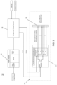
FIG. 1 is a block diagram of a skin rejuvenation device according to an embodiment of the description; -
FIG. 2 is a block diagram of a skin rejuvenation device according to an embodiment of the description; -
FIG. 3 is a block diagram of a skin rejuvenation device according to an embodiment of the description; -
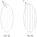
FIGS. 4A and 4B show alternate applicator nodes according to an embodiment of the description; and -
FIGS. 5A and 5B show alternate applicator head shapes according to an embodiment of the description; - Referring now to the drawings and the illustrative embodiment depicted therein, a
device 10 to rejuvenate skin is disclosed. Further details of a skin rejuvenation device may be found in commonly assignedU.S. Patent No. 8,954,155 , entitled APPARATUS AND METHOD FOR REJUVENATING SKIN. - As shown in
FIG. 1 , thedevice 10 includes apower supply 12 that is adapted to generating a voltage. The device also includes anapplicator 14. Theapplicator 14 is adapted to be pressed against or near the skin or tissue to be rejuvenated. Theapplicator 14 includes at least twonodes 16. A first node is adapted to be configurable between a positive electrode electrically coupled to thepower supply 12 or electrically isolated from thepower supply 12. A second node is adapted to be configurable between a negative electrode electrically coupled to thepower supply 12 or electrically isolated from thepower supply 12. Thepower supply 12 delivers a current through the first node when the first node is configured as the positive electrode, and current returns to the power supply through the second node when the second node is configured to be the negative electrode. - The
power supply 12 is adapted to output a DC voltage. Thepower supply 12 may be adapted to accept a variety of voltage inputs. For example, thepower supply 12 may be adapted to receive 110V AC voltage. The power supply may include a battery that is charged to provide power while thedevice 10 is not connected to an external voltage source. Thepower supply 12 may include a smart charging circuit to provide protection for the battery from charging and temperature. Thepower supply 12 may provide voltage conversion to provide the rest of thedevice 10 appropriate voltage. For example, the power supply may incorporate AC/DC conversion or DC/DC conversion. - The
device 10 also includesapplicator 14 for a user to press to an area to be treated. Thepower supply 12 may be separate from theapplicator 14, such that thepower supply 12 provides power to theapplicator 14 through a cord or wire. Alternatively, thepower supply 12 may be integrated into theapplicator 14, wherein the battery in thepower supply 12 provides power to theapplicator 14 while in use. The applicator may include anapplicator head 22. Theapplicator head 22 includes the surface of the applicator that is applied to tissue. The surface may be a variety of shapes. For example, the surface may be flat. Alternatively, as shown in the illustrated embodiment ofFIG. 5A and FIG. 5B , the surface may be convex. A convex surface facilitates contact with the various natural contours of the face, including, but not limited to, the naso-labial, periorbital, and glabellar frown areas. Theapplicator 14 orapplicator head 22 includes a plurality ofnodes 16 adapted to come in contact with skin or tissue to be treated. - The nodes may be a variety of shapes. For example, in the illustrated embodiments of
FIG. 4A and FIG. 4B , thenodes 16 are pin shaped, and blade shaped, respectively. However, other shapes are applicable. Each node is adapted to be configured in one of two states: coupled electrically to the power supply, or alternatively electrically isolated from the power supply. This state is commonly known as "floating." In such a state, no current is conducted through the node due to an external potential difference of a power source. At least onenode 16 is configured to be either floating or a positive electrode. Hereinafter, a positive electrode refers to an electrode that may be configured between these two states. At least onenode 16 is configured to be either floating or a negative electrode. Hereinafter, a negative electrode refers to an electrode that may be configured between these two states. When configured to be coupled electrically to thepower supply 12, the positive electrodes conduct current provided by thepower supply 12 to the skin. When configured to be coupled electrically to the power supply, the negative electrodes conduct current from the skin back to thepower supply 12. In this way, current will flow from thepower supply 12, through the positive electrode, through the skin to the negative electrode, and back to the power supply. When either type ofnode 16 is configured to be floating, the node will not conduct any current to or from the tissue. This ensures that inactive electrodes do not interfere with the character of the signal transmitted to the skin. - The device may also include a signal generator or
voltage control unit 18. Thevoltage control 18 may be adapted to modulate a frequency of the voltage provided by thepower supply 12 and to the positive electrodes. Furthermore, thevoltage control 18 may also be adapted to provide a wide range of other features, such as modulating the amplitude, pulse rate, pulse sweep, and duty cycle of the voltage provided by the power supply. This provides for fine control of the stimulation of the tissue by providing the means to control the specific pattern and signal characteristics of the signal. Thevoltage control 18 may provide the signal to an amplification anddistribution unit 20. The amplification and distribution unit may amplify the signal and provide the proper circuitry for selectively configuring the nodes between possible states. The circuitry may include solid state switching to control the configuration of thenodes 16. Thevoltage control unit 18 may be separate from theapplicator 14 and instead integrated with thepower supply 12 into a base unit. Alternatively, thevoltage control 18 may be integrated into theapplicator 14. - While at least one positive electrode may be used to conduct current to the skin, a negative electrode does not need to be provided to return current. Instead, if all negative electrodes are configured to be electrically isolated, the current can be dissipated through the skin. During this dissipation period, the positive electrodes may also be electrically isolated, allowing for a period where no energy is delivered to the skin. In such a way, the tissue can be provided with a "rest period" to be allowed to return to its natural electrical condition. Nodes can also be selectively disabled to provide different patterns of contact with the skin. Additionally, the
voltage control unit 18 may be used to generate periodic or intermittent positive voltage to be delivered to the tissue and then cease generating during a negative phase of the signal. In such a manner, thevoltage control unit 18 can supply the periodic "rest" pattern independent of the node configuration. This allows for flexible methods to provide additional stimulation to the tissue. - In another aspect of the description, each node instead may be selectively configurable between three states: a positive electrode, a negative electrode, and floating. This aspect provides for complex and dynamic patterns of tissue stimulation. For example, patterns such as linear, circular, or spiral "waves" may be applied and this may optimize the treatment of a broad range of skin conditions. As shown in
FIG. 2 , thedevice 100 includespower supply 112. Thedevice 100 also includesnodes 116 onapplicator 114 that may be dynamically and flexibly configured as positive, negative, or floating. The configuration of thenodes 116 are controlled by thevoltage control unit 118. Thevoltage control unit 118 may control the signal in a manner similar to thecontrol unit 18, but accounts for the three possible states of each node. - Referring now to
FIG. 3 , in another aspect of the description, thedevice 200 includes anapplicator 214 that may be adapted to have adetachable applicator head 222. Eachapplicator head 222 may have a distinct pattern of positive andnegative electrodes 216 to apply stimulation to tissue. By exchanging different applicator heads 222, the device may provide varying patterns without including the switching and other circuitry in theapplicator 214. Theapplicator 214 may couple with theapplicator head 222 with aconnector 224 that provides the positive and negative path for the stimulation signal. Theapplicator head 222 may also provide aseparate identification signal 226 to thevoltage control 218. In this way, thevoltage control 218 can identify thespecific applicator head 222 currently attached to theapplicator 214 and adjust the signal accordingly. Thevoltage control unit 218 may provide similar functionality as in the other aspects of the invention. - In each aspect of the description; the device may include a means to update or change the software or operation of the device. For example, operation of the voltage control unit may be updated, including the frequency or voltage of the signal supplied to skin or other tissue. The pattern of node activation may also be configured. The device may be updated through a physical connection, such as USB, or through a wireless connection, such as WiFi or Bluetooth. Each aspect of the invention may be a hand-held device. Alternatively, the applicator may be separate from a base containing the power supply and voltage control unit and electrically coupled via a cord or wire.
- While the foregoing description describes several embodiments, it will be understood by those skilled in the art that variations and modifications to these embodiments may be made. The invention is set out in the appended claims.
Claims (11)
- A skin rejuvenation device, the device comprising:a power supply adapted to generate a voltage and having at least two output terminals, said power supply providing a positive polarity between one of said at least two output terminals and ground and a negative polarity between another of said at least two terminals and ground;an applicator comprising an applicator head, wherein the applicator head comprises a plurality of spaced apart nodes, comprising a plurality of first nodes and a plurality of second nodes said first and second nodes adapted to come into contact with the skin to be treated, anda control adapted to selectively connect each of said nodes with one of said at least two output terminal of said power supply and to selectively allow each of said nodes to float with respect to said at least two output terminal, wherein said control is adapted to configure the first nodes as positive electrodes electrically coupled to the positive electrode power supply terminal or electrically isolated from the power supply, and wherein said control is adapted to configure the second nodes as negative electrodes electrically coupled to the negative electrode power supply terminal or electrically isolated from the power supply; andwherein the power supply delivers a current through the first nodes when the first nodes are configured as positive electrodes and current returns to the power supply through the second nodes when the second nodes are configured to be the negative electrodes, wherein no current is delivered to or from the skin when said control isolates said two nodes from the power supply to define a dissipation period during which current is dissipated through the skin.
- The device of claim 1, wherein the control is adapted to modulate a frequency of the voltage between 1,000 Hz and 350,000 Hz.
- The device of claim 2, wherein the voltage control is further adapted to modulate at least one of an amplitude, pulse rate, pulse sweep, and duty cycle of the voltage.
- The device of claim 1, wherein the applicator head further comprises a convex surface, wherein the first node and the second node are disposed on the convex surface.
- The device of claim 1, wherein the power supply is adapted to deliver a periodic voltage comprising of a first period of positive voltage through at least one selected from said first nodes and said second nodes followed by a second period of no voltage through any of the nodes.
- The device as claimed in claim 1 wherein said control applies said output terminal to at least one of said nodes to activate that node and allows that node to float to discharge that node.
- The device as claimed in claim 1 wherein said at least one output terminal comprises at least two output terminals, said power supply providing a particular polarity between one of said output terminals and ground and an opposite polarity between other of said output terminals and ground.
- The device as claimed in claim 7 wherein said control is adapted to selectively connect each of said nodes with one of said output terminals, the other of said output terminals or to float.
- The device as claimed in claim 8, wherein said plurality of said nodes comprise a plurality of third nodes, wherein at least some of said third nodes are between one of said first nodes and one of said second nodes, wherein said control is adapted to selectively connect said first nodes with one of said output terminals, said second nodes with said other of said output terminals and said third nodes to float in order to define a first pattern wherein only said first and second nodes are activated.
- The device as claimed in claim 9, wherein said control is adapted to connect alternating ones of said nodes with said one of said output terminals and the other of said output terminals and to float to define a second wave pattern wherein stimulation travels in a linear, circular or spiral wave pattern.
- A method for rejuvenating skin, the method comprising:generating a voltage with a power supply having at least two output terminals and providing a positive polarity between one of said at least two output terminals and ground and a negative polarity between another of said at least two terminals and ground ;having an applicator comprising an applicator head, wherein the applicator head comprises a plurality of spaced apart nodes, comprising a plurality of first nodes and a plurality of second nodes, said first and second nodes adapted to come into contact with the skin to be treated,selectively connecting each of said nodes with one of said at least two output terminals of said power supply and selectively allowing each of said nodes to float with respect to said at least one output terminal, including configuring the first nodes as positive electrodes electrically coupled to the positive polarity power supply output terminal or electrically isolated from the power supply and configuring the second nodes as negative electrodes electrically coupled to the negative polarity power supply terminal or electrically isolated from the power supply; andwherein the power supply delivers a current through the first nodes when the first nodes are configured as positive electrodes and current returns to the power supply through the second nodes when the second nodes are configured to be the negative electrodes and delivering no current to or from the skin when the first and second nodes are isolated from the power supply to define a dissipation period during which current is dissipated through the skin.
Applications Claiming Priority (2)
| Application Number | Priority Date | Filing Date | Title |
|---|---|---|---|
| US201762553372P | 2017-09-01 | 2017-09-01 | |
| PCT/IB2018/056649 WO2019043628A2 (en) | 2017-09-01 | 2018-08-30 | Skin rejuvenation device and method |
Publications (4)
| Publication Number | Publication Date |
|---|---|
| EP3675952A2 EP3675952A2 (en) | 2020-07-08 |
| EP3675952A4 EP3675952A4 (en) | 2021-05-19 |
| EP3675952B1 true EP3675952B1 (en) | 2024-07-17 |
| EP3675952C0 EP3675952C0 (en) | 2024-07-17 |
Family
ID=65526404
Family Applications (1)
| Application Number | Title | Priority Date | Filing Date |
|---|---|---|---|
| EP18851091.1A Active EP3675952B1 (en) | 2017-09-01 | 2018-08-30 | Skin rejuvenation device and method |
Country Status (11)
| Country | Link |
|---|---|
| US (1) | US11420048B2 (en) |
| EP (1) | EP3675952B1 (en) |
| KR (1) | KR102591545B1 (en) |
| CN (2) | CN111315442B (en) |
| AU (1) | AU2018326833B9 (en) |
| CA (1) | CA3074598C (en) |
| ES (1) | ES2992047T3 (en) |
| MX (1) | MX2020002306A (en) |
| PL (1) | PL3675952T3 (en) |
| RU (1) | RU2020111269A (en) |
| WO (1) | WO2019043628A2 (en) |
Families Citing this family (9)
| Publication number | Priority date | Publication date | Assignee | Title |
|---|---|---|---|---|
| US20180001107A1 (en) | 2016-07-01 | 2018-01-04 | Btl Holdings Limited | Aesthetic method of biological structure treatment by magnetic field |
| US10695575B1 (en) | 2016-05-10 | 2020-06-30 | Btl Medical Technologies S.R.O. | Aesthetic method of biological structure treatment by magnetic field |
| US11464993B2 (en) | 2016-05-03 | 2022-10-11 | Btl Healthcare Technologies A.S. | Device including RF source of energy and vacuum system |
| RU2020111269A (en) * | 2017-09-01 | 2021-10-04 | Хэр Текнолоджис, Инк. | METHOD AND DEVICE FOR SKIN REJUVENATION |
| US12558146B2 (en) | 2019-04-11 | 2026-02-24 | Btl Medical Solutions A.S. | Methods and devices for aesthetic treatment of biological structures by radiofrequency and magnetic energy |
| US12611545B2 (en) | 2020-05-04 | 2026-04-28 | Btl Healthcare Technologies A.S. | Device and method for unattended treatment of a patient |
| JP2023515722A (en) | 2020-05-04 | 2023-04-13 | ビーティーエル ヘルスケア テクノロジーズ エー.エス. | Devices and methods for unattended care of patients |
| US11878167B2 (en) | 2020-05-04 | 2024-01-23 | Btl Healthcare Technologies A.S. | Device and method for unattended treatment of a patient |
| US20260097226A1 (en) | 2024-10-08 | 2026-04-09 | Btl Medical Solutions A.S. | Devices and methods for application of a magnetic field to the nervous system |
Citations (1)
| Publication number | Priority date | Publication date | Assignee | Title |
|---|---|---|---|---|
| US20140343625A1 (en) * | 2011-11-11 | 2014-11-20 | University Of Limerick | Muscle stimulation device |
Family Cites Families (18)
| Publication number | Priority date | Publication date | Assignee | Title |
|---|---|---|---|---|
| US6708060B1 (en) * | 1998-11-09 | 2004-03-16 | Transpharma Ltd. | Handheld apparatus and method for transdermal drug delivery and analyte extraction |
| GB2422549A (en) * | 2005-02-01 | 2006-08-02 | Wound Solutions Ltd | Flexible electrodes comprising a honey-comb mesh and integrated wound stimulation treatment devices |
| US7319902B2 (en) * | 2005-05-09 | 2008-01-15 | O'kelly Gregory | Method and device for electrochemical rejuvenation of skin and underlying tissue, and muscle building |
| GB0709834D0 (en) * | 2007-05-22 | 2007-07-04 | Gillbe Ivor S | Array stimulator |
| US20090326602A1 (en) * | 2008-06-27 | 2009-12-31 | Arkady Glukhovsky | Treatment of indications using electrical stimulation |
| KR20120028879A (en) * | 2009-04-16 | 2012-03-23 | 이노비오 파마수티컬즈, 인크. | Contactless electropermeabilization electrode and method |
| US20100274329A1 (en) | 2009-04-24 | 2010-10-28 | Chris Bradley | System and method for skin care using light and microcurrents |
| CN201643407U (en) * | 2010-05-19 | 2010-11-24 | 段雪民 | Wrinkle filler |
| US20160151238A1 (en) * | 2011-09-15 | 2016-06-02 | Sigma Instruments Holdings, Llc | System and Method for Treating Skin and Underlying Tissues for Improved Health, Function and/or Appearance |
| US8954155B2 (en) * | 2011-09-19 | 2015-02-10 | Biotalk Technologies Inc | Apparatus and method for rejuvenating skin |
| WO2013059699A1 (en) * | 2011-10-19 | 2013-04-25 | Neuro Resource Group Inc | Automated electrode array treatment protocol |
| GB2496895A (en) | 2011-11-25 | 2013-05-29 | Cyden Ltd | Skin treatment apparatus |
| US9295850B2 (en) * | 2012-04-24 | 2016-03-29 | Medtronic, Inc. | Charge-balancing during electrical stimulation |
| US20140194949A1 (en) * | 2013-01-04 | 2014-07-10 | Brian D. Wichner | Multiplex Electrodes for Applying Transcutaneous Interferential Current |
| WO2014196195A1 (en) * | 2013-06-04 | 2014-12-11 | ヤーマン株式会社 | High frequency cosmetic treatment device |
| CN205764438U (en) * | 2015-02-09 | 2016-12-07 | 司浦爱激光技术英国有限公司 | Laser welded seam and the article including laser welded seam |
| HK1246713A1 (en) | 2015-05-29 | 2018-09-14 | 赛威医疗公司 | Methods and apparatuses for transdermal electrical stimulation |
| RU2020111269A (en) * | 2017-09-01 | 2021-10-04 | Хэр Текнолоджис, Инк. | METHOD AND DEVICE FOR SKIN REJUVENATION |
-
2018
- 2018-08-30 RU RU2020111269A patent/RU2020111269A/en unknown
- 2018-08-30 WO PCT/IB2018/056649 patent/WO2019043628A2/en not_active Ceased
- 2018-08-30 MX MX2020002306A patent/MX2020002306A/en unknown
- 2018-08-30 US US16/643,382 patent/US11420048B2/en active Active
- 2018-08-30 CN CN201880066075.6A patent/CN111315442B/en active Active
- 2018-08-30 CN CN202311302487.4A patent/CN117258148A/en active Pending
- 2018-08-30 CA CA3074598A patent/CA3074598C/en active Active
- 2018-08-30 KR KR1020207009494A patent/KR102591545B1/en active Active
- 2018-08-30 PL PL18851091.1T patent/PL3675952T3/en unknown
- 2018-08-30 ES ES18851091T patent/ES2992047T3/en active Active
- 2018-08-30 AU AU2018326833A patent/AU2018326833B9/en not_active Ceased
- 2018-08-30 EP EP18851091.1A patent/EP3675952B1/en active Active
Patent Citations (1)
| Publication number | Priority date | Publication date | Assignee | Title |
|---|---|---|---|---|
| US20140343625A1 (en) * | 2011-11-11 | 2014-11-20 | University Of Limerick | Muscle stimulation device |
Also Published As
| Publication number | Publication date |
|---|---|
| PL3675952T3 (en) | 2024-12-02 |
| WO2019043628A3 (en) | 2020-02-06 |
| EP3675952A2 (en) | 2020-07-08 |
| AU2018326833A1 (en) | 2020-03-19 |
| EP3675952A4 (en) | 2021-05-19 |
| RU2020111269A3 (en) | 2022-01-27 |
| AU2018326833B2 (en) | 2024-02-29 |
| CN111315442A (en) | 2020-06-19 |
| CN111315442B (en) | 2023-10-13 |
| CA3074598C (en) | 2024-05-07 |
| RU2020111269A (en) | 2021-10-04 |
| CA3074598A1 (en) | 2019-03-07 |
| WO2019043628A2 (en) | 2019-03-07 |
| US20210069502A1 (en) | 2021-03-11 |
| MX2020002306A (en) | 2020-10-28 |
| US11420048B2 (en) | 2022-08-23 |
| AU2018326833B9 (en) | 2024-03-28 |
| CN117258148A (en) | 2023-12-22 |
| KR102591545B1 (en) | 2023-10-18 |
| EP3675952C0 (en) | 2024-07-17 |
| KR20200073209A (en) | 2020-06-23 |
| ES2992047T3 (en) | 2024-12-05 |
Similar Documents
| Publication | Publication Date | Title |
|---|---|---|
| EP3675952B1 (en) | Skin rejuvenation device and method | |
| EP3197552B1 (en) | Skin treatment appliance with changeable workpiece | |
| EP3446745B1 (en) | Beauty apparatus | |
| KR101649603B1 (en) | Apparatus for beauty care using high radio frequency with cross-linked electrodes | |
| CN110139691B (en) | Electric therapeutic apparatus, electric therapeutic system and storage medium | |
| KR102023654B1 (en) | Portable high frequency scalp massage stimulator automatic regulating of high frequency level | |
| US11826567B2 (en) | Electrical treatment device, control method, and treatment system | |
| CN107800406B (en) | High-frequency pulse stimulation signal generation method, pulse stimulation method and equipment | |
| KR101829015B1 (en) | A Massage Type of a Health Device Having a Structure of Applying a Micro Current | |
| KR101912851B1 (en) | Functional Skin Caring Apparatus having water peeling mode and multi-ion mode with hybrid power supply | |
| CN109908476B (en) | A wearable multimodal wireless neurostimulation system | |
| HK40104462A (en) | Skin rejuvenation device and method | |
| JP2019201990A (en) | Electrotherapy device and therapy system | |
| CN217612505U (en) | Programmable low-frequency functional electrical stimulation signal generating circuit with electric signal monitoring | |
| KR20250063577A (en) | Skin management apparatus with changeable operation mode based on user's skin condition | |
| JP2025185753A (en) | Facial beauty device, facial beauty device control method, and facial beauty device control program | |
| CN120960638A (en) | Wearable transcranial electric stimulation equipment based on electrode combination and control method thereof | |
| KR20230037767A (en) | Self-Managed Energy Therapy Multifunction Device | |
| JP2025073437A (en) | skin beauty device | |
| TWM498024U (en) | Power output switch circuit of electrotherapy machine | |
| JPH02268770A (en) | Apparatus for low frequency medical treatment |
Legal Events
| Date | Code | Title | Description |
|---|---|---|---|
| STAA | Information on the status of an ep patent application or granted ep patent |
Free format text: STATUS: THE INTERNATIONAL PUBLICATION HAS BEEN MADE |
|
| PUAI | Public reference made under article 153(3) epc to a published international application that has entered the european phase |
Free format text: ORIGINAL CODE: 0009012 |
|
| STAA | Information on the status of an ep patent application or granted ep patent |
Free format text: STATUS: REQUEST FOR EXAMINATION WAS MADE |
|
| 17P | Request for examination filed |
Effective date: 20200320 |
|
| AK | Designated contracting states |
Kind code of ref document: A2 Designated state(s): AL AT BE BG CH CY CZ DE DK EE ES FI FR GB GR HR HU IE IS IT LI LT LU LV MC MK MT NL NO PL PT RO RS SE SI SK SM TR |
|
| AX | Request for extension of the european patent |
Extension state: BA ME |
|
| DAV | Request for validation of the european patent (deleted) | ||
| DAX | Request for extension of the european patent (deleted) | ||
| A4 | Supplementary search report drawn up and despatched |
Effective date: 20210414 |
|
| RIC1 | Information provided on ipc code assigned before grant |
Ipc: A61N 1/18 20060101AFI20210409BHEP Ipc: A61N 1/36 20060101ALI20210409BHEP Ipc: A61N 1/04 20060101ALI20210409BHEP |
|
| GRAP | Despatch of communication of intention to grant a patent |
Free format text: ORIGINAL CODE: EPIDOSNIGR1 |
|
| STAA | Information on the status of an ep patent application or granted ep patent |
Free format text: STATUS: GRANT OF PATENT IS INTENDED |
|
| RIC1 | Information provided on ipc code assigned before grant |
Ipc: A61N 1/04 20060101ALI20240129BHEP Ipc: A61N 1/36 20060101ALI20240129BHEP Ipc: A61N 1/18 20060101AFI20240129BHEP |
|
| INTG | Intention to grant announced |
Effective date: 20240214 |
|
| GRAS | Grant fee paid |
Free format text: ORIGINAL CODE: EPIDOSNIGR3 |
|
| GRAA | (expected) grant |
Free format text: ORIGINAL CODE: 0009210 |
|
| STAA | Information on the status of an ep patent application or granted ep patent |
Free format text: STATUS: THE PATENT HAS BEEN GRANTED |
|
| AK | Designated contracting states |
Kind code of ref document: B1 Designated state(s): AL AT BE BG CH CY CZ DE DK EE ES FI FR GB GR HR HU IE IS IT LI LT LU LV MC MK MT NL NO PL PT RO RS SE SI SK SM TR |
|
| REG | Reference to a national code |
Ref country code: CH Ref legal event code: EP |
|
| REG | Reference to a national code |
Ref country code: DE Ref legal event code: R096 Ref document number: 602018071979 Country of ref document: DE |
|
| REG | Reference to a national code |
Ref country code: IE Ref legal event code: FG4D |
|
| U01 | Request for unitary effect filed |
Effective date: 20240815 |
|
| U07 | Unitary effect registered |
Designated state(s): AT BE BG DE DK EE FI FR IT LT LU LV MT NL PT RO SE SI Effective date: 20240903 |
|
| REG | Reference to a national code |
Ref country code: ES Ref legal event code: FG2A Ref document number: 2992047 Country of ref document: ES Kind code of ref document: T3 Effective date: 20241205 |
|
| U20 | Renewal fee for the european patent with unitary effect paid |
Year of fee payment: 7 Effective date: 20241119 |
|
| PG25 | Lapsed in a contracting state [announced via postgrant information from national office to epo] |
Ref country code: NO Free format text: LAPSE BECAUSE OF FAILURE TO SUBMIT A TRANSLATION OF THE DESCRIPTION OR TO PAY THE FEE WITHIN THE PRESCRIBED TIME-LIMIT Effective date: 20241017 |
|
| PG25 | Lapsed in a contracting state [announced via postgrant information from national office to epo] |
Ref country code: GR Free format text: LAPSE BECAUSE OF FAILURE TO SUBMIT A TRANSLATION OF THE DESCRIPTION OR TO PAY THE FEE WITHIN THE PRESCRIBED TIME-LIMIT Effective date: 20241018 |
|
| PG25 | Lapsed in a contracting state [announced via postgrant information from national office to epo] |
Ref country code: IS Free format text: LAPSE BECAUSE OF FAILURE TO SUBMIT A TRANSLATION OF THE DESCRIPTION OR TO PAY THE FEE WITHIN THE PRESCRIBED TIME-LIMIT Effective date: 20241117 |
|
| PG25 | Lapsed in a contracting state [announced via postgrant information from national office to epo] |
Ref country code: HR Free format text: LAPSE BECAUSE OF FAILURE TO SUBMIT A TRANSLATION OF THE DESCRIPTION OR TO PAY THE FEE WITHIN THE PRESCRIBED TIME-LIMIT Effective date: 20240717 |
|
| PG25 | Lapsed in a contracting state [announced via postgrant information from national office to epo] |
Ref country code: RS Free format text: LAPSE BECAUSE OF THE APPLICANT RENOUNCES; INVALID AB INITIO Effective date: 20180830 |
|
| PG25 | Lapsed in a contracting state [announced via postgrant information from national office to epo] |
Ref country code: RS Free format text: LAPSE BECAUSE OF THE APPLICANT RENOUNCES; INVALID AB INITIO Effective date: 20180830 Ref country code: NO Free format text: LAPSE BECAUSE OF FAILURE TO SUBMIT A TRANSLATION OF THE DESCRIPTION OR TO PAY THE FEE WITHIN THE PRESCRIBED TIME-LIMIT Effective date: 20241017 Ref country code: IS Free format text: LAPSE BECAUSE OF FAILURE TO SUBMIT A TRANSLATION OF THE DESCRIPTION OR TO PAY THE FEE WITHIN THE PRESCRIBED TIME-LIMIT Effective date: 20241117 Ref country code: HR Free format text: LAPSE BECAUSE OF FAILURE TO SUBMIT A TRANSLATION OF THE DESCRIPTION OR TO PAY THE FEE WITHIN THE PRESCRIBED TIME-LIMIT Effective date: 20240717 Ref country code: GR Free format text: LAPSE BECAUSE OF FAILURE TO SUBMIT A TRANSLATION OF THE DESCRIPTION OR TO PAY THE FEE WITHIN THE PRESCRIBED TIME-LIMIT Effective date: 20241018 |
|
| REG | Reference to a national code |
Ref country code: CH Ref legal event code: PL |
|
| PG25 | Lapsed in a contracting state [announced via postgrant information from national office to epo] |
Ref country code: SM Free format text: LAPSE BECAUSE OF FAILURE TO SUBMIT A TRANSLATION OF THE DESCRIPTION OR TO PAY THE FEE WITHIN THE PRESCRIBED TIME-LIMIT Effective date: 20240717 |
|
| PG25 | Lapsed in a contracting state [announced via postgrant information from national office to epo] |
Ref country code: MC Free format text: LAPSE BECAUSE OF FAILURE TO SUBMIT A TRANSLATION OF THE DESCRIPTION OR TO PAY THE FEE WITHIN THE PRESCRIBED TIME-LIMIT Effective date: 20240717 Ref country code: CH Free format text: LAPSE BECAUSE OF NON-PAYMENT OF DUE FEES Effective date: 20240831 |
|
| PG25 | Lapsed in a contracting state [announced via postgrant information from national office to epo] |
Ref country code: CZ Free format text: LAPSE BECAUSE OF FAILURE TO SUBMIT A TRANSLATION OF THE DESCRIPTION OR TO PAY THE FEE WITHIN THE PRESCRIBED TIME-LIMIT Effective date: 20240717 |
|
| PG25 | Lapsed in a contracting state [announced via postgrant information from national office to epo] |
Ref country code: SK Free format text: LAPSE BECAUSE OF FAILURE TO SUBMIT A TRANSLATION OF THE DESCRIPTION OR TO PAY THE FEE WITHIN THE PRESCRIBED TIME-LIMIT Effective date: 20240717 |
|
| PLBE | No opposition filed within time limit |
Free format text: ORIGINAL CODE: 0009261 |
|
| STAA | Information on the status of an ep patent application or granted ep patent |
Free format text: STATUS: NO OPPOSITION FILED WITHIN TIME LIMIT |
|
| 26N | No opposition filed |
Effective date: 20250422 |
|
| GBPC | Gb: european patent ceased through non-payment of renewal fee |
Effective date: 20241017 |
|
| PG25 | Lapsed in a contracting state [announced via postgrant information from national office to epo] |
Ref country code: GB Free format text: LAPSE BECAUSE OF NON-PAYMENT OF DUE FEES Effective date: 20241017 |
|
| PG25 | Lapsed in a contracting state [announced via postgrant information from national office to epo] |
Ref country code: IE Free format text: LAPSE BECAUSE OF NON-PAYMENT OF DUE FEES Effective date: 20240830 |
|
| REG | Reference to a national code |
Ref country code: ES Ref legal event code: FD2A Effective date: 20251002 |
|
| PG25 | Lapsed in a contracting state [announced via postgrant information from national office to epo] |
Ref country code: ES Free format text: LAPSE BECAUSE OF NON-PAYMENT OF DUE FEES Effective date: 20240831 |
|
| PG25 | Lapsed in a contracting state [announced via postgrant information from national office to epo] |
Ref country code: PL Free format text: LAPSE BECAUSE OF NON-PAYMENT OF DUE FEES Effective date: 20240830 |
|
| PG25 | Lapsed in a contracting state [announced via postgrant information from national office to epo] |
Ref country code: CY Free format text: LAPSE BECAUSE OF FAILURE TO SUBMIT A TRANSLATION OF THE DESCRIPTION OR TO PAY THE FEE WITHIN THE PRESCRIBED TIME-LIMIT; INVALID AB INITIO Effective date: 20180830 |
|
| PG25 | Lapsed in a contracting state [announced via postgrant information from national office to epo] |
Ref country code: HU Free format text: LAPSE BECAUSE OF FAILURE TO SUBMIT A TRANSLATION OF THE DESCRIPTION OR TO PAY THE FEE WITHIN THE PRESCRIBED TIME-LIMIT; INVALID AB INITIO Effective date: 20180830 |
|
| U90 | Renewal fees not paid: noting of loss of rights |
Free format text: RENEWAL FEE NOT PAID FOR YEAR 08 Effective date: 20260323 |