EP3675915B1 - Systems and methods for instrument disinfection and anti-microbial coating - Google Patents
Systems and methods for instrument disinfection and anti-microbial coating Download PDFInfo
- Publication number
- EP3675915B1 EP3675915B1 EP18852013.4A EP18852013A EP3675915B1 EP 3675915 B1 EP3675915 B1 EP 3675915B1 EP 18852013 A EP18852013 A EP 18852013A EP 3675915 B1 EP3675915 B1 EP 3675915B1
- Authority
- EP
- European Patent Office
- Prior art keywords
- vapor
- instrument
- chamber
- core
- chamber body
- Prior art date
- Legal status (The legal status is an assumption and is not a legal conclusion. Google has not performed a legal analysis and makes no representation as to the accuracy of the status listed.)
- Active
Links
Images




Classifications
-
- A—HUMAN NECESSITIES
- A61—MEDICAL OR VETERINARY SCIENCE; HYGIENE
- A61L—METHODS OR APPARATUS FOR STERILISING MATERIALS OR OBJECTS IN GENERAL; DISINFECTION, STERILISATION OR DEODORISATION OF AIR; CHEMICAL ASPECTS OF BANDAGES, DRESSINGS, ABSORBENT PADS OR SURGICAL ARTICLES; MATERIALS FOR BANDAGES, DRESSINGS, ABSORBENT PADS OR SURGICAL ARTICLES
- A61L2/00—Disinfection or sterilisation of materials or objects, in general; Accessories therefor
- A61L2/16—Disinfection or sterilisation of materials or objects, in general; Accessories therefor using chemical substances
- A61L2/20—Gaseous substances, e.g. vapours
-
- A—HUMAN NECESSITIES
- A61—MEDICAL OR VETERINARY SCIENCE; HYGIENE
- A61L—METHODS OR APPARATUS FOR STERILISING MATERIALS OR OBJECTS IN GENERAL; DISINFECTION, STERILISATION OR DEODORISATION OF AIR; CHEMICAL ASPECTS OF BANDAGES, DRESSINGS, ABSORBENT PADS OR SURGICAL ARTICLES; MATERIALS FOR BANDAGES, DRESSINGS, ABSORBENT PADS OR SURGICAL ARTICLES
- A61L2/00—Disinfection or sterilisation of materials or objects, in general; Accessories therefor
- A61L2/02—Disinfection or sterilisation of materials or objects, in general; Accessories therefor using physical processes
- A61L2/04—Heat
- A61L2/06—Hot gas
- A61L2/07—Steam
-
- A—HUMAN NECESSITIES
- A61—MEDICAL OR VETERINARY SCIENCE; HYGIENE
- A61B—DIAGNOSIS; SURGERY; IDENTIFICATION
- A61B90/00—Instruments, implements or accessories specially adapted for surgery or diagnosis and not covered by any of the groups A61B1/00 - A61B50/00, e.g. for luxation treatment or for protecting wound edges
- A61B90/70—Cleaning devices specially adapted for surgical instruments
-
- A—HUMAN NECESSITIES
- A61—MEDICAL OR VETERINARY SCIENCE; HYGIENE
- A61B—DIAGNOSIS; SURGERY; IDENTIFICATION
- A61B90/00—Instruments, implements or accessories specially adapted for surgery or diagnosis and not covered by any of the groups A61B1/00 - A61B50/00, e.g. for luxation treatment or for protecting wound edges
- A61B90/70—Cleaning devices specially adapted for surgical instruments
- A61B2090/701—Cleaning devices specially adapted for surgical instruments for flexible tubular instruments, e.g. endoscopes
-
- A—HUMAN NECESSITIES
- A61—MEDICAL OR VETERINARY SCIENCE; HYGIENE
- A61L—METHODS OR APPARATUS FOR STERILISING MATERIALS OR OBJECTS IN GENERAL; DISINFECTION, STERILISATION OR DEODORISATION OF AIR; CHEMICAL ASPECTS OF BANDAGES, DRESSINGS, ABSORBENT PADS OR SURGICAL ARTICLES; MATERIALS FOR BANDAGES, DRESSINGS, ABSORBENT PADS OR SURGICAL ARTICLES
- A61L2103/00—Materials or objects being the target of disinfection or sterilisation
- A61L2103/15—Laboratory, medical or dentistry appliances, e.g. catheters or sharps
-
- A—HUMAN NECESSITIES
- A61—MEDICAL OR VETERINARY SCIENCE; HYGIENE
- A61L—METHODS OR APPARATUS FOR STERILISING MATERIALS OR OBJECTS IN GENERAL; DISINFECTION, STERILISATION OR DEODORISATION OF AIR; CHEMICAL ASPECTS OF BANDAGES, DRESSINGS, ABSORBENT PADS OR SURGICAL ARTICLES; MATERIALS FOR BANDAGES, DRESSINGS, ABSORBENT PADS OR SURGICAL ARTICLES
- A61L2202/00—Aspects relating to methods or apparatus for disinfecting or sterilising materials or objects
- A61L2202/10—Apparatus features
- A61L2202/12—Apparatus for isolating biocidal substances from the environment
- A61L2202/122—Chambers for sterilisation
-
- A—HUMAN NECESSITIES
- A61—MEDICAL OR VETERINARY SCIENCE; HYGIENE
- A61L—METHODS OR APPARATUS FOR STERILISING MATERIALS OR OBJECTS IN GENERAL; DISINFECTION, STERILISATION OR DEODORISATION OF AIR; CHEMICAL ASPECTS OF BANDAGES, DRESSINGS, ABSORBENT PADS OR SURGICAL ARTICLES; MATERIALS FOR BANDAGES, DRESSINGS, ABSORBENT PADS OR SURGICAL ARTICLES
- A61L2202/00—Aspects relating to methods or apparatus for disinfecting or sterilising materials or objects
- A61L2202/10—Apparatus features
- A61L2202/14—Means for controlling sterilisation processes, data processing, presentation and storage means, e.g. sensors, controllers, programs
Definitions
- the present invention as set out in the claims relates to a disinfecting chamber and a method of disinfecting a surface of an instrument.
- Various types of medical devices or instruments such as metallic syringes, scalpels, forceps, hemostats, and endoscopes may become contaminated as a result of use or exposure to contaminants from time to time.
- scalpels and forceps may be used for performing medical procedures (e.g ., surgical procedures, etc.) during which the scalpel or forceps may come into contact with or otherwise become exposed to contaminants, such as through physical contact with a patient or other potentially contaminated areas.
- medical procedures e.g ., surgical procedures, etc.
- reusable instruments must be disinfected to remove contaminants before they may be suitable for reuse.
- Techniques known in the art for disinfecting an instrument's surfaces may include exposing the surfaces to disinfecting conditions, such as high temperatures, sonic waves, or applying a disinfecting substance or solution to a surface of the instrument. Such techniques may include physically applying a disinfecting solution to the surface of the instrument. As an example, instruments may be placed into various apparatuses for exposing the instruments to disinfecting conditions. In some implementations, the disinfection process may require application of a combination of techniques in order to achieve the desired disinfection of the instrument.
- CN204684243U discloses a medical instrument high pressure sterilizing instrument.
- US9149036B1 discloses a method for applying a persistent antimicrobial film.
- the instrument may remain disinfected until subsequent exposure to contaminants, at which point it must be disinfected again. Steps may be taken to prevent such re-contamination of previously disinfected instruments, such as by separately applying various solutions to the instrument. However, even when such solutions are applied, contamination of a previously disinfected instrument may occur during the time between disinfection and application of the anti-microbial solution. Such contamination may be undetectable to a user, and a risk of use of a contaminated instrument for such applications is increased. Thus, improved techniques preventing contamination of disinfected instruments are generally desirable.
- the present invention is directed to disinfecting chamber as set out in claim 1.
- the instrument may comprise an endoscope, and in some embodiments, the endoscope may be a rigid endoscope.
- an instrument disinfection system may comprise a vapor source, wherein the vapor source is configured to provide a dry steam vapor, and a disinfecting chamber coupled to receive the vapor from the vapor source, wherein the vapor contacts a surface of an instrument within the chamber, wherein the vapor disinfects the surface of the instrument, and wherein an antimicrobial film is deposited on the surface of the instrument.
- the system also may comprise a vapor core positioned within the disinfecting chamber, wherein the vapor core comprises a channel for channeling the vapor when received by the vapor core, and wherein the vapor core comprises at least one hole for passing the vapor into an interior of the chamber.
- the vapor may comprise a chitosan vapor solution, which may be most 0.003% chitosan vapor.
- the system may further comprise at least one disc coupled to the vapor core, wherein the disc holds the instrument.
- the instrument may comprise an endoscope, and may be a rigid endoscope.
- the vapor may comprise a dry steam vapor, which may comprise a chitosan vapor solution.
- the chitosan solution may be at most 0.003% chitosan.
- the instrument may be an endoscope.
- a disinfection chamber is arranged to receive a disinfecting vapor from a vapor source and channeling it to contact a surface of an instrument within the chamber.
- the vapor source provides the vapor to the disinfecting chamber via an inlet in a chamber cover of the chamber.
- a vapor core within the disinfecting chamber channels the vapor from the inlet through a length of the vapor core.
- a portion of the vapor passes from an interior of the vapor core and contact the surface of the instrument. When the vapor contacts the surface, the vapor disinfects the surface, and deposits an anti-microbial film on the surface.
- FIG. 1 depicts a three-dimensional orthogonal view of an instrument disinfection system 5 in accordance with some embodiments of the present invention.
- the embodiment of system 5 depicted by FIG. 1 has a chamber body 10 and chamber cover 20.
- the chamber body 10 is configured to couple to chamber cover 20 to form a substantially closed disinfecting chamber, as described further below.
- An instrument (not specifically shown in FIG. 1 ) is held adjacent to a vapor core 30, which is contained within the chamber body 10 when the chamber cover 20 is coupled to the chamber body 10.
- a vapor source (not shown in FIG.
- a disinfecting vapor via an inlet 22 of the chamber cover 20, which is channeled by the vapor core 30 and passed into an interior of the chamber body 10 to contact a surface of the instrument for disinfecting instrument surface and depositing an anti-microbial film on the surface.
- Chamber body 10 is configured for coupling to the chamber cover 20 and receiving the vapor core 30.
- chamber body 10 is essentially hollow, and may include a first end 12 configured to couple to the chamber cover 20 and to receive the vapor core 30, and a second end 14 configured to support the chamber body 10.
- the first end 12 of the chamber body 10 is be substantially open for receiving the vapor core 30 and coupling to the chamber cover 20, and may include various components or be configured suitably for coupling to the chamber cover 20 to achieve the functionality described herein.
- the second end 14 of the chamber body 10 may have components for supporting the chamber body 10 (e.g., both when coupled to the chamber cover 20 or otherwise), such as one or more legs 15.
- the chamber body 10 may include at least one leg 15 adjacent to the second end 14 for supporting the chamber body 10 while simultaneously providing clearance for a chamber drain 17 of the chamber body 10, described in further detail below.
- chamber body 10 may have an essentially circular crosssectional area, and may be configured such that a longitudinal axis of the chamber body is essentially perpendicular to a surface supporting the chamber body 10 (e.g., oriented vertically).
- the chamber body 10 may have other cross-sectional shapes and may be oriented otherwise in other embodiments, such as for accommodating instruments having other types, sizes, shapes or features.
- the chamber body 10 of FIG. 1 is fabricated from a metal, such as an aluminum alloy, but in other embodiments, the chamber body 10 may be fabricated from other materials or combinations of materials and may comprise various components and materials for achieving the functionality described herein. In some embodiments, the chamber body 10 may be fabricated using a combination of various materials suitable for exposure to conditions required of a chamber for disinfecting instruments ( e.g ., exposure to various temperature, pressure, chemical, or other conditions).
- Chamber cover 20 is configured for coupling to the chamber body 10 and configured to receive the disinfecting vapor from a vapor source.
- the chamber cover 20 has an inlet 22 on a top side of the chamber cover that is configured to receive the vapor, such as by coupling to the vapor source or otherwise.
- the chamber cover 20 is coupled to a vapor core 30 that is configured to receive vapors from inlet 22 of the chamber cover 20.
- the vapor core 30 may have a length that corresponds to a length of the chamber body 10, and is configured to channel the vapor along a length of the vapor core 30 (e.g., along a longitudinal axis of the vapor core 30).
- FIG. 1 depicts a disc 32 coupled to the vapor core 30 for holding at least one instrument (not specifically shown in FIG. 1 ) adjacent to the vapor core 30.
- various numbers of shelves 32 are coupled to the vapor core 30, and are configured for holding various types and quantities of instruments adjacent to the vapor core 30.
- the disc 32 of FIG. 1 is shown empty, a portion of the at least one instrument is loaded (e.g., inserted) into one or more portions of the disc 32 (e.g., slots, holes, or otherwise) such that the at least one instrument is held substantially adjacent to the vapor core 30.
- FIG. 1 depicts a disc 32 coupled to the vapor core 30 for holding at least one instrument (not specifically shown in FIG. 1 ) adjacent to the vapor core 30.
- various numbers of shelves 32 are coupled to the vapor core 30, and are configured for holding various types and quantities of instruments adjacent to the vapor core 30.
- the disc 32 of FIG. 1 is shown empty, a portion of the at least one instrument is loaded (e.g.,
- FIG. 1 depicts a disc 32 with a plurality of slots 34, but the disc 32 are configured as having various features for holding various types of instruments, and such features correspond to a portion and type of instrument to be held.
- slots 34 have characteristics (e.g ., diameter, width, length, etc.) for accommodating a portion of an endoscope.
- the disc 32 may comprise a mesh having holes through which a portion of an instrument may be inserted. Other configurations are possible in other embodiments.
- a plurality of vapor cores 30 may be coupled to the chamber cover 20, and each may be coupled to various numbers and types of discs 32 for holding various numbers and types of instruments.
- chamber cover 20 is be coupled to the chamber body 10 as depicted in FIGs. 2 and 3.
- FIG. 2 depicts a side view of the instrument disinfection system 5
- FIG. 3 depicts a cross-sectional side view of the system 5.
- chamber cover 20 may be coupled to chamber body 10 by positioning chamber cover 20 over the first end 12 of chamber body 10 and inserting the vapor core 30 within the interior of chamber body 10 until the chamber cover 20 suitably contacts chamber body 10 or is otherwise suitably positioned with respect to the chamber body 10.
- the chamber cover 20 is be coupled ( e.g ., fastened, screwed, latched, etc.) to the chamber body 10 after it has been suitably positioned.
- cross sectional shapes of the chamber body 10 and chamber cover 20 may generally correspond such that when fitted together, a substantially sealed chamber of system 5 is formed.
- the chamber cover 20 and chamber body 10 may form such a substantially sealed chamber when coupled together, which may be suitable for containing a disinfecting vapor and achieving a desired exposure to the vapor for instruments within system 5.
- the inlet 22 is configured for receiving the vapor and channeling it to the vapor core 30.
- a diameter of the inlet 22 corresponds to a diameter of the vapor core 30, but the inlet 22 may have various suitable cross-sections and configurations in other embodiments.
- the inlet 22 is essentially configured as a tube or conduit to which a vapor source may be coupled (e.g., via hose, tube or otherwise) for receiving and channeling the vapor essentially without leakage or pressure loss between the vapor source and inlet 22.
- the inlet 22 may have various components or hardware for coupling to a vapor source, such as a gasket, clamp, collar, or otherwise.
- Vapor received via the inlet 22 is channeled through an interior of the vapor core 30 along a longitudinal axis of the vapor core 30.
- the vapor core 30 has a plurality of holes 305 configured to permit vapor to pass from an interior of the vapor core 30 through each of the holes 305. Although a particular number and arrangement of holes 305 is depicted in FIG. 3 , various numbers, sizes, configurations and arrangements of the holes 305 are possible in other embodiments.
- a portion of the vapor passes from an interior of the vapor core 30 through one or more holes 305 (e.g., to an interior of the chamber body 10) and contacts a surface of the at least one instrument.
- vapor is provided via the inlet 22 and channeled through the vapor core 30 into the interior of the chamber body 20 for a desired amount of time or until a desired volume of vapor has been introduced into the interior of the chamber (e.g ., coupled chamber cover 20 and chamber body 10), such as until substantially all of the interior of the chamber body 10 is filled with vapor or otherwise.
- vapor core 30 may have various dimensions relative to the chamber body 10.
- the vapor core 30 may have a diameter that is sufficiently smaller than a diameter of the chamber body 10 such that a desired quantity of desired instruments are held (e.g., by disc 32 or otherwise) between an outer surface of the vapor core 30 and an inner surface of the interior of the chamber body 10.
- a length (height, when oriented vertically) of vapor core 30 may vary relative to a length (e.g., height when oriented vertically) of chamber body 10.
- vapor core 30 may be configured to fit completely within a chamber formed when the chamber cover 20 and chamber body 10 are coupled together.
- the vapor core 30 may have a length that permits condensed fluid to escape via a condensate drain 17, as described hereafter.
- Other dimensions of the vapor core 30 are possible in other embodiments.
- the second end of the chamber body 10 shown in the embodiment of system 5 depicted in FIGs. 2 and 3 also has a plurality of legs 15 configured to support the chamber body 10 and a condensate drain 17.
- a particular number of legs 15 is depicted by FIGs. 2 and 3 , various numbers of legs 15 may be used in other embodiments as desired to support components of the system 5 as desired and suitably for achieving the functionality described herein.
- the condensate drain 17 of FIGs. 2 and 3 is positioned on the second end 14 of the chamber body 10.
- the system 5 may be configured to direct condensed fluid from an interior of the chamber cover 20 and chamber body 10 out of the chamber via the drain 17.
- a condensate may form on an interior surface of the chamber body 10.
- condensate may run along a length of the chamber body 10 and toward and eventually into the drain 17.
- a cap 19 may be coupled to the drain 17 as desired, and may be configured to prevent escape of substances inside the chamber body 10, to maintain insulation or temperature properties of the system 5, or otherwise.
- the cap 19 also can be removed as desired for removing substances from the chamber body 10, such as by allowing gravity to remove liquid condensed within the chamber body 10 via the drain 17 or otherwise.
- various numbers of drains 17 and respective caps 19 are possible, and may be configured according to various techniques for creating an opening to the interior of the chamber body 10 as may be desired.
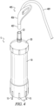
- FIGs. 4 and 5 depict a disinfection system 5 and vapor source 405 in accordance with some embodiments of the present invention.
- FIG. 4 the vapor source 405 is depicted as detached from the inlet 22 of system 5, as the source 405 may be positioned just before or after coupling to the inlet 22 for providing disinfecting vapor to the system 5.
- FIG. 5 depicts the vapor source 405 coupled to the inlet 22, such as when providing the vapor.
- FIGs. 4 and 5 it will be understood that various components and configurations of each of the system 5 and vapor source 405 it is possible to achieve the functionality described herein.
- the vapor source 405 provides a disinfecting vapor, which, in some embodiments, is configured to chemically disinfect instrument surfaces exposed to the vapor.
- a desired amount of the disinfecting vapor may be provided from the vapor source 405 to the system 5 (e.g., to the interior of the chamber body 10 via inlet 22 of chamber cover 20 and vapor core 30). The amount may be based on a volume of the system 5, number of instruments for disinfection, or other information.
- the vapor may be provided to the system 5 so that the instrument surfaces are exposed to the vapor.
- the vapor may be provided at a desired temperature and pressure, and the instruments may be exposed to the vapor for a desired amount of time to achieve the desired disinfecting.
- the vapor provided to the system 5 from the vapor source 405 may be provided as a dry steam vapor.
- the vapor may be introduced to system 5 at a suitable temperature, such as approximately 300° C or otherwise.
- the vapor may cool to a temperature of approximately at least 75° C while inside the system 5 (e.g., chamber body 10), but other temperatures are possible in other embodiments.
- the vapor may be provided from vapor source 405 at a suitable temperature and pressure according to various information, such as regulatory guidelines specifying standards for the respective vapor composition, experimentally determined value ranges or conditions, application specific conditions, user-defined conditions, or otherwise.
- the dry steam vapor may comprise various components (e.g ., substances, compounds, chemicals, or other constituent parts) suitable for achieving a desired disinfection or sterilization of an instrument surface.
- the vapor may comprise an acid, such as a peracetic acid, for achieving disinfection.
- a portion of the vapor may be water, such as may be required when the vapor is a dry steam vapor.
- the vapor may have other components in other embodiments.
- the vapor comprises a long-chain polysaccharide compound, such as chitosan.
- the vapor comprises various amounts of chitosan, but in some embodiments, the chitosan solution comprises approximately 0.003% chitosan.
- the vapor may comprise other amounts of chitosan in other embodiments.
- the vapor comprising chitosan is provided to the chamber body 10 via the vapor source 405 as described above. In this regard, the vapor may contact the surface of the at least one instrument and thereby disinfect the surface.
- the vapor deposits an anti-microbial film onto the surface of the at least one instrument. In other embodiments, deposition of an anti-microbial film onto an instrument's surface may be performed using other compounds having similar features (e.g ., various long-chain polysaccharide compounds).
- the vapor source 405 may be coupled to system 5 to provide the disinfecting vapor addressed above.
- vapor source 405 is depicted as a device with a handheld actuator 406 for controlling flow of vapor from within the vapor source 405 into the system 5 via inlet 22, such as by use of a trigger on the actuator 406 or otherwise.
- the actuator of vapor source 405 may have a nozzle 407 that may be fitted within inlet 22, which may allow vapor to be pumped or otherwise provided to the chamber cover 20 while reducing or essentially eliminating leakage or pressure loss.
- vapor source 405 may be plumbed ( e.g ., permanently coupled) to the inlet 22 to provide a desired amount of vapor to the system 5 without requiring coupling to the vapor source 405 in each instance.
- additional hardware or components may be required, any of which vapor source 405 may comprise.
- Vapor source 405 may use other suitable components that correspond to other techniques for providing vapor to the system 5 in other embodiments.
- the vapor source 405 has a flexible tube 409 configured to carry the vapor to the system 5 (e.g., inlet 22).
- the tube 409 may be coupled to a vapor reservoir of the vapor source 405 (not shown in FIGs. 4 and 5 ), such as may be used to store an amount of the vapor until use by system 5.
- a pump or other power source may be used to propel vapor through the tube 409 and into the system 5.
- the tube 409 may facilitate transportation of the vapor from the vapor reservoir to the system 5, such as by pressurized pumping or otherwise.
- Vapor source 405 may utilize other components for providing vapor from the vapor reservoir in other embodiments.
- the vapor provided from vapor source 405 may be of various types and compositions for disinfecting a surface of an instrument and within the chamber body 10.
- the vapor source 405 is configured for providing a heated, dry steam disinfecting vapor.
- the vapor may be provided at temperature that exceeds a temperature required for performing disinfection of surfaces of instruments within the system 5, such as at least approximately 75 °C or otherwise.
- the vapor may be provided at a desired pressure, such as approximately 1 atmosphere (1 ATM) or otherwise.
- the vapor source 405 may comprise components for ensuring that the vapor is provided at a desired temperature and pressure.
- FIGs in some embodiments not specifically shown in FIGs.
- system 5 may include various components (e.g ., pressure sensors, thermocouples, thermometers, etc.) for sensing temperature of the vapor at various locations within system 5, such as within the vapor core 30, chamber body 10, or otherwise.
- components e.g ., pressure sensors, thermocouples, thermometers, etc.
- Such components may be coupled to various displays (e.g., gauges, monitors, etc.) for providing output indicative of a sensed temperature, pressure, or other characteristic of the vapor in the vicinity of the respective components.
- a user of system 5 may be able to monitor conditions within the system 5 to ensure that desired conditions and a desired performance of the system 5 are achieved.
- FIGs. 6 and 7 depict a vapor core 30 of a disinfection system 5 in accordance with some embodiments of the present invention.
- the vapor core 30 of FIG. 6 is depicted as having a collar 605 configured for coupling to the vapor core 30 and supporting a disc 32 (not specifically shown in FIG. 6 ).
- the collar 605 is configured to surround a portion of vapor core 30 and to couple to the vapor core 30 at a desired location along a length of the vapor core 30.
- the collar 605 may be movable with respect to the vapor core 30, and may be configured for coupling and decoupling to the vapor core 30 as desired.
- system 5 may include a plurality of collars 605 configured for coupling to the vapor core 30, such as for coupling to a corresponding number of discs 32 to achieve holding of a desired number of instruments. It will be appreciated by one skilled in the art upon reading of this invention that discs 32 may be coupled to the vapor core or otherwise within the chamber according to other techniques in other embodiments.
- the collar 605 of FIG. 6 may comprise an upper portion 607 and lower portion 609, which may be separated by a groove 611.
- the upper portion 607 and lower portion 609 may have suitable dimensions for supporting a disc 32 that may be configured for holding a desired number of instruments.
- the groove 611 may essentially comprise a channel having suitable dimensions ( e.g ., thickness, depth, etc.) for coupling to at least one shelf 32.
- the collar 605 may include various components for coupling to the vapor core 30 and for coupling to and supporting disc 32, such as snaps, clips, pins, or otherwise.
- a disc 32 may be coupled to the vapor core 30 via collar 605, and may be movable along the length of the vapor core when the collar 605 is decoupled from the vapor core. Further, in embodiments in which the system 5 comprises a plurality of discs 32, each respective disc 32 may be positioned by positioning its respective collar 605, as desired. Other techniques for coupling a disc 32 to a collar 605 may be possible in other embodiments.
- the vapor core 30 has a plurality of holes 305 that are configured for permitting the disinfecting vapor to pass from an interior of the vapor core 30 to the interior of the chamber body 10 and contacting instruments therein.
- Vapor passes through one or more holes 305 at a rate that corresponds to a pressure applied to the vapor ( e.g ., by vapor source 405 or otherwise).
- the vapor core 30 channels the vapor along a length of the vapor core 30, and a portion of the vapor flows through a hole of the vapor core 30.
- Other portions of the vapor may pass through one or more additional holes 305 until a desired volume of vapor has passed from the vapor core 30 into the interior of the chamber body.
- the holes 305 may have suitable dimensions and quantities to achieve a desired exposure to the vapor of an instrument within the chamber body 10 (e.g., and chamber cover 20).
- the vapor core 30 may have various quantities, positions and configurations of holes 305 in some embodiments, and in some embodiments, holes 305 may have varying characteristics ( e.g ., diameters, positions, etc.) for achieving a desired exposure ( e.g ., vapor flow through the holes 305).
- FIG. 7 depicts a chamber cover 20 and vapor core 30 having a disc 32 positioned to hold a plurality of instruments 705.
- the instruments 705 of embodiment of FIG. 7 are depicted as endoscopes, but, as described herein, various types of instruments 705 are possible.
- the disc 32 of FIG. 7 is configured to hold the endoscopes 705 via a plurality of corresponding slots 34, as depicted in FIG. 1 and described herein.
- Each endoscope 705 is held substantially adjacent to the vapor core 30, such that vapor passing from the holes 305 may contact a surface of the endoscopes 705 for performing disinfection and depositing an anti-microbial coating as described herein.
- one or more instrument types may be held by one or more discs 32 for achieving the functionality described herein.
- a chamber for disinfecting instruments using a disinfecting vapor may be configured by coupling a chamber cover 20 to a chamber body 10. Before coupling the chamber cover 20 to the chamber body 10, one or more instruments 705 are loaded into a disc 32 coupled to a vapor core 30 and configured for holding the instruments 705. After the instruments 705 are loaded into the disc 32, the chamber cover 20 is coupled to the chamber body 10 so that the vapor core 30 and instruments is essentially contained within an interior space of the chamber body 10. In this regard, the instrument 705 held by the disc 32 coupled to the vapor core 30 may be contained within the chamber formed when the chamber cover 20 is coupled to the chamber body 10.
- a vapor source 405 may be coupled to the inlet 22 of chamber cover 20 to provide a disinfecting vapor.
- the vapor may flow (e.g., in response to a pressure applied to the vapor) from vapor source 405 (e.g., via tube 409 in response to operation of the actuator 406) and pass through the inlet 22 and into vapor core 30.
- the vapor may be that may be channeled along a length the vapor core 30 and passed through holes 305 into the interior of the chamber body 10.
- the vapor may be dispersed and essentially fill the space within the interior of the chamber body 10.
- the vapor contacts a surface of an instrument 705 within the chamber body 10 ( e.g ., adjacent to the vapor core 30) to perform desired disinfection of the surface.
- the chamber body 10 may essentially contain the vapor ( e.g ., may be pressurized) so that the surface of the instrument 705 may be exposed to the vapor for a desired period of time.
- the vapor may be a dry steam vapor, and may comprise a long-chain polysaccharide, such as chitosan.
- the instrument 705 may be exposed to the vapor for a desired amount of time such that when the vapor contacts surfaces of the instrument 705, the vapor disinfects the surface of the instrument 705, and deposits an antimicrobial film onto the surface.
- disinfection and deposition of an antimicrobial film on a surface of an instrument 705 may be accomplished in a single step.
Landscapes
- Health & Medical Sciences (AREA)
- Life Sciences & Earth Sciences (AREA)
- Animal Behavior & Ethology (AREA)
- Veterinary Medicine (AREA)
- Public Health (AREA)
- General Health & Medical Sciences (AREA)
- Epidemiology (AREA)
- Surgery (AREA)
- General Chemical & Material Sciences (AREA)
- Chemical Kinetics & Catalysis (AREA)
- Chemical & Material Sciences (AREA)
- Molecular Biology (AREA)
- Engineering & Computer Science (AREA)
- Pathology (AREA)
- Oral & Maxillofacial Surgery (AREA)
- Nuclear Medicine, Radiotherapy & Molecular Imaging (AREA)
- Biomedical Technology (AREA)
- Medical Informatics (AREA)
- Heart & Thoracic Surgery (AREA)
- Apparatus For Disinfection Or Sterilisation (AREA)
Description
- This application claims priority to
U.S. Application No. 15/687,657 filed on August 28, 2017 - The present invention as set out in the claims relates to a disinfecting chamber and a method of disinfecting a surface of an instrument.
- Various types of medical devices or instruments, such as metallic syringes, scalpels, forceps, hemostats, and endoscopes may become contaminated as a result of use or exposure to contaminants from time to time. For example, scalpels and forceps may be used for performing medical procedures (e.g., surgical procedures, etc.) during which the scalpel or forceps may come into contact with or otherwise become exposed to contaminants, such as through physical contact with a patient or other potentially contaminated areas. In many applications, only noncontaminated or sterile instruments may be used. Thus, reusable instruments must be disinfected to remove contaminants before they may be suitable for reuse.
- Techniques known in the art for disinfecting an instrument's surfaces may include exposing the surfaces to disinfecting conditions, such as high temperatures, sonic waves, or applying a disinfecting substance or solution to a surface of the instrument. Such techniques may include physically applying a disinfecting solution to the surface of the instrument. As an example, instruments may be placed into various apparatuses for exposing the instruments to disinfecting conditions. In some implementations, the disinfection process may require application of a combination of techniques in order to achieve the desired disinfection of the instrument.
CN204684243U discloses a medical instrument high pressure sterilizing instrument.US9149036B1 - Generally, after the instrument has been disinfected, it may remain disinfected until subsequent exposure to contaminants, at which point it must be disinfected again. Steps may be taken to prevent such re-contamination of previously disinfected instruments, such as by separately applying various solutions to the instrument. However, even when such solutions are applied, contamination of a previously disinfected instrument may occur during the time between disinfection and application of the anti-microbial solution. Such contamination may be undetectable to a user, and a risk of use of a contaminated instrument for such applications is increased. Thus, improved techniques preventing contamination of disinfected instruments are generally desirable.
- The present invention is directed to disinfecting chamber as set out in claim 1. The instrument may comprise an endoscope, and in some embodiments, the endoscope may be a rigid endoscope.
- According to another aspect not forming part of the invention, an instrument disinfection system may comprise a vapor source, wherein the vapor source is configured to provide a dry steam vapor, and a disinfecting chamber coupled to receive the vapor from the vapor source, wherein the vapor contacts a surface of an instrument within the chamber, wherein the vapor disinfects the surface of the instrument, and wherein an antimicrobial film is deposited on the surface of the instrument. The system also may comprise a vapor core positioned within the disinfecting chamber, wherein the vapor core comprises a channel for channeling the vapor when received by the vapor core, and wherein the vapor core comprises at least one hole for passing the vapor into an interior of the chamber. The vapor may comprise a chitosan vapor solution, which may be most 0.003% chitosan vapor. The system may further comprise at least one disc coupled to the vapor core, wherein the disc holds the instrument. The instrument may comprise an endoscope, and may be a rigid endoscope.
- In yet another aspect of the invention, there is provided, a method as set out in claim 2. The vapor may comprise a dry steam vapor, which may comprise a chitosan vapor solution. The chitosan solution may be at most 0.003% chitosan. In addition, the instrument may be an endoscope.
- The invention can be better understood with reference to the following drawings. The elements of the drawings are not necessarily to scale relative to each other, emphasis instead being placed upon clearly illustrating the principles of the invention.
-
FIG. 1 depicts a three-dimensional perspective view of an instrument disinfection system in accordance with some embodiments of the present invention. -
FIG. 2 depicts a side view of an instrument disinfection system in accordance with some embodiments of the present invention. -
FIG. 3 depicts a cross-sectional side view of an instrument disinfection system in accordance with some embodiments of the present invention. -
FIG. 4 depicts a three-dimensional perspective view of an instrument disinfection system and vapor source in accordance with some embodiments of the present invention. -
FIG. 5 depicts a three-dimensional perspective view of an instrument disinfection system and vapor source in accordance with some embodiments of the present invention. -
FIG. 6 depicts a three-dimensional perspective view of a chamber cover of an instrument disinfection system in accordance with some embodiments of the present invention. -
FIG. 7 depicts a three-dimensional perspective view of a chamber cover of an instrument disinfection system holding a plurality of instruments in accordance with some embodiments of the present invention. - The present invention generally pertains to disinfecting chambers and methods for disinfecting and depositing anti-microbial coating on an instrument surface. In some embodiments, a disinfection chamber is arranged to receive a disinfecting vapor from a vapor source and channeling it to contact a surface of an instrument within the chamber. The vapor source provides the vapor to the disinfecting chamber via an inlet in a chamber cover of the chamber. A vapor core within the disinfecting chamber channels the vapor from the inlet through a length of the vapor core. A portion of the vapor passes from an interior of the vapor core and contact the surface of the instrument. When the vapor contacts the surface, the vapor disinfects the surface, and deposits an anti-microbial film on the surface.
-
FIG. 1 depicts a three-dimensional orthogonal view of an instrument disinfection system 5 in accordance with some embodiments of the present invention. The embodiment of system 5 depicted byFIG. 1 has achamber body 10 andchamber cover 20. Thechamber body 10 is configured to couple tochamber cover 20 to form a substantially closed disinfecting chamber, as described further below. An instrument (not specifically shown inFIG. 1 ) is held adjacent to avapor core 30, which is contained within thechamber body 10 when thechamber cover 20 is coupled to thechamber body 10. A vapor source (not shown inFIG. 1 ) provides a disinfecting vapor via aninlet 22 of thechamber cover 20, which is channeled by thevapor core 30 and passed into an interior of thechamber body 10 to contact a surface of the instrument for disinfecting instrument surface and depositing an anti-microbial film on the surface. -
Chamber body 10 is configured for coupling to thechamber cover 20 and receiving thevapor core 30. As shown inFIG. 1 ,chamber body 10 is essentially hollow, and may include afirst end 12 configured to couple to thechamber cover 20 and to receive thevapor core 30, and asecond end 14 configured to support thechamber body 10. Thefirst end 12 of thechamber body 10 is be substantially open for receiving thevapor core 30 and coupling to thechamber cover 20, and may include various components or be configured suitably for coupling to thechamber cover 20 to achieve the functionality described herein. Thesecond end 14 of thechamber body 10 may have components for supporting the chamber body 10 (e.g., both when coupled to thechamber cover 20 or otherwise), such as one ormore legs 15. In some embodiments, thechamber body 10 may include at least oneleg 15 adjacent to thesecond end 14 for supporting thechamber body 10 while simultaneously providing clearance for achamber drain 17 of thechamber body 10, described in further detail below. In some embodiments,chamber body 10 may have an essentially circular crosssectional area, and may be configured such that a longitudinal axis of the chamber body is essentially perpendicular to a surface supporting the chamber body 10 (e.g., oriented vertically). Thechamber body 10 may have other cross-sectional shapes and may be oriented otherwise in other embodiments, such as for accommodating instruments having other types, sizes, shapes or features. - The
chamber body 10 ofFIG. 1 is fabricated from a metal, such as an aluminum alloy, but in other embodiments, thechamber body 10 may be fabricated from other materials or combinations of materials and may comprise various components and materials for achieving the functionality described herein. In some embodiments, thechamber body 10 may be fabricated using a combination of various materials suitable for exposure to conditions required of a chamber for disinfecting instruments (e.g., exposure to various temperature, pressure, chemical, or other conditions). -
Chamber cover 20 is configured for coupling to thechamber body 10 and configured to receive the disinfecting vapor from a vapor source. Thechamber cover 20 has aninlet 22 on a top side of the chamber cover that is configured to receive the vapor, such as by coupling to the vapor source or otherwise. Thechamber cover 20 is coupled to avapor core 30 that is configured to receive vapors frominlet 22 of thechamber cover 20. Thevapor core 30 may have a length that corresponds to a length of thechamber body 10, and is configured to channel the vapor along a length of the vapor core 30 (e.g., along a longitudinal axis of the vapor core 30). - The embodiment of
FIG. 1 depicts adisc 32 coupled to thevapor core 30 for holding at least one instrument (not specifically shown inFIG. 1 ) adjacent to thevapor core 30. As will be described in further detail below, various numbers ofshelves 32 are coupled to thevapor core 30, and are configured for holding various types and quantities of instruments adjacent to thevapor core 30. Although thedisc 32 ofFIG. 1 is shown empty, a portion of the at least one instrument is loaded (e.g., inserted) into one or more portions of the disc 32 (e.g., slots, holes, or otherwise) such that the at least one instrument is held substantially adjacent to thevapor core 30.FIG. 1 depicts adisc 32 with a plurality ofslots 34, but thedisc 32 are configured as having various features for holding various types of instruments, and such features correspond to a portion and type of instrument to be held. For example,slots 34 have characteristics (e.g., diameter, width, length, etc.) for accommodating a portion of an endoscope. In some embodiments, thedisc 32 may comprise a mesh having holes through which a portion of an instrument may be inserted. Other configurations are possible in other embodiments. In some embodiments, a plurality ofvapor cores 30 may be coupled to thechamber cover 20, and each may be coupled to various numbers and types ofdiscs 32 for holding various numbers and types of instruments. - After a desired quantity of instruments has been inserted into portions of the
disc 32, thechamber cover 20 is be coupled to thechamber body 10 as depicted inFIGs. 2 and 3. FIG. 2 depicts a side view of the instrument disinfection system 5, andFIG. 3 depicts a cross-sectional side view of the system 5. In some embodiments, chamber cover 20 may be coupled tochamber body 10 by positioningchamber cover 20 over thefirst end 12 ofchamber body 10 and inserting thevapor core 30 within the interior ofchamber body 10 until thechamber cover 20 suitablycontacts chamber body 10 or is otherwise suitably positioned with respect to thechamber body 10. In some embodiments, thechamber cover 20 is be coupled (e.g., fastened, screwed, latched, etc.) to thechamber body 10 after it has been suitably positioned. Note that cross sectional shapes of thechamber body 10 and chamber cover 20 may generally correspond such that when fitted together, a substantially sealed chamber of system 5 is formed. In this regard, thechamber cover 20 andchamber body 10 may form such a substantially sealed chamber when coupled together, which may be suitable for containing a disinfecting vapor and achieving a desired exposure to the vapor for instruments within system 5. - After the
chamber cover 20 has been coupled to thechamber body 10, vapor from a vapor source is provided to an interior of thechamber body 10 via theinlet 22 of thechamber cover 20. As depicted inFIG. 3 , theinlet 22 is configured for receiving the vapor and channeling it to thevapor core 30. In some embodiments, a diameter of theinlet 22 corresponds to a diameter of thevapor core 30, but theinlet 22 may have various suitable cross-sections and configurations in other embodiments. In an embodiment, theinlet 22 is essentially configured as a tube or conduit to which a vapor source may be coupled (e.g., via hose, tube or otherwise) for receiving and channeling the vapor essentially without leakage or pressure loss between the vapor source andinlet 22. In other embodiments, theinlet 22 may have various components or hardware for coupling to a vapor source, such as a gasket, clamp, collar, or otherwise. - Vapor received via the
inlet 22 is channeled through an interior of thevapor core 30 along a longitudinal axis of thevapor core 30. Thevapor core 30 has a plurality ofholes 305 configured to permit vapor to pass from an interior of thevapor core 30 through each of theholes 305. Although a particular number and arrangement ofholes 305 is depicted inFIG. 3 , various numbers, sizes, configurations and arrangements of theholes 305 are possible in other embodiments. As an example of operation of thevapor core 30, when the vapor is channeled along the vapor core 30 (e.g., as propelled by a force applied to the vapor, via gravity, or otherwise), a portion of the vapor passes from an interior of thevapor core 30 through one or more holes 305 (e.g., to an interior of the chamber body 10) and contacts a surface of the at least one instrument. In some embodiments, vapor is provided via theinlet 22 and channeled through thevapor core 30 into the interior of thechamber body 20 for a desired amount of time or until a desired volume of vapor has been introduced into the interior of the chamber (e.g., coupledchamber cover 20 and chamber body 10), such as until substantially all of the interior of thechamber body 10 is filled with vapor or otherwise. - Note that
vapor core 30 may have various dimensions relative to thechamber body 10. For example, thevapor core 30 may have a diameter that is sufficiently smaller than a diameter of thechamber body 10 such that a desired quantity of desired instruments are held (e.g., bydisc 32 or otherwise) between an outer surface of thevapor core 30 and an inner surface of the interior of thechamber body 10. In addition, a length (height, when oriented vertically) ofvapor core 30 may vary relative to a length (e.g., height when oriented vertically) ofchamber body 10. In this regard,vapor core 30 may be configured to fit completely within a chamber formed when thechamber cover 20 andchamber body 10 are coupled together. In addition, as shown byFIG. 3 , thevapor core 30 may have a length that permits condensed fluid to escape via acondensate drain 17, as described hereafter. Other dimensions of thevapor core 30 are possible in other embodiments. - The second end of the
chamber body 10 shown in the embodiment of system 5 depicted inFIGs. 2 and 3 also has a plurality oflegs 15 configured to support thechamber body 10 and acondensate drain 17. Although a particular number oflegs 15 is depicted byFIGs. 2 and 3 , various numbers oflegs 15 may be used in other embodiments as desired to support components of the system 5 as desired and suitably for achieving the functionality described herein. In addition, thecondensate drain 17 ofFIGs. 2 and 3 is positioned on thesecond end 14 of thechamber body 10. In some embodiments, the system 5 may be configured to direct condensed fluid from an interior of thechamber cover 20 andchamber body 10 out of the chamber via thedrain 17. For example, when disinfecting vapor is introduced into system 5 (e.g., interior of chamber body 10), a condensate may form on an interior surface of thechamber body 10. When the system 5 is oriented such that the second end of thechamber body 10 is below the condensate (e.g., the chamber body is upright), condensate may run along a length of thechamber body 10 and toward and eventually into thedrain 17. Acap 19 may be coupled to thedrain 17 as desired, and may be configured to prevent escape of substances inside thechamber body 10, to maintain insulation or temperature properties of the system 5, or otherwise. Thecap 19 also can be removed as desired for removing substances from thechamber body 10, such as by allowing gravity to remove liquid condensed within thechamber body 10 via thedrain 17 or otherwise. In some embodiments, various numbers ofdrains 17 andrespective caps 19 are possible, and may be configured according to various techniques for creating an opening to the interior of thechamber body 10 as may be desired. -
FIGs. 4 and5 depict a disinfection system 5 andvapor source 405 in accordance with some embodiments of the present invention.FIG. 4 , thevapor source 405 is depicted as detached from theinlet 22 of system 5, as thesource 405 may be positioned just before or after coupling to theinlet 22 for providing disinfecting vapor to the system 5.FIG. 5 depicts thevapor source 405 coupled to theinlet 22, such as when providing the vapor. Although particular components of thevapor source 405 are depicted inFIGs. 4 and5 , it will be understood that various components and configurations of each of the system 5 andvapor source 405 it is possible to achieve the functionality described herein. - As noted herein, the
vapor source 405 provides a disinfecting vapor, which, in some embodiments, is configured to chemically disinfect instrument surfaces exposed to the vapor. For example, a desired amount of the disinfecting vapor may be provided from thevapor source 405 to the system 5 (e.g., to the interior of thechamber body 10 viainlet 22 ofchamber cover 20 and vapor core 30). The amount may be based on a volume of the system 5, number of instruments for disinfection, or other information. The vapor may be provided to the system 5 so that the instrument surfaces are exposed to the vapor. As described below, the vapor may be provided at a desired temperature and pressure, and the instruments may be exposed to the vapor for a desired amount of time to achieve the desired disinfecting. For example, in some embodiments, where the disinfecting vapor comprises a particular chemical for enhancing disinfection or sterilization of the instruments (e.g., peracetic acid or otherwise), the vapor provided to the system 5 from thevapor source 405 may be provided as a dry steam vapor. The vapor may be introduced to system 5 at a suitable temperature, such as approximately 300° C or otherwise. The vapor may cool to a temperature of approximately at least 75° C while inside the system 5 (e.g., chamber body 10), but other temperatures are possible in other embodiments. In addition, in some embodiments, the vapor may be provided fromvapor source 405 at a suitable temperature and pressure according to various information, such as regulatory guidelines specifying standards for the respective vapor composition, experimentally determined value ranges or conditions, application specific conditions, user-defined conditions, or otherwise. - Note that the dry steam vapor may comprise various components (e.g., substances, compounds, chemicals, or other constituent parts) suitable for achieving a desired disinfection or sterilization of an instrument surface. In some embodiments, the vapor may comprise an acid, such as a peracetic acid, for achieving disinfection. A portion of the vapor may be water, such as may be required when the vapor is a dry steam vapor. The vapor may have other components in other embodiments.
- In some embodiments, the vapor comprises a long-chain polysaccharide compound, such as chitosan. The vapor comprises various amounts of chitosan, but in some embodiments, the chitosan solution comprises approximately 0.003% chitosan. The vapor may comprise other amounts of chitosan in other embodiments. The vapor comprising chitosan is provided to the
chamber body 10 via thevapor source 405 as described above. In this regard, the vapor may contact the surface of the at least one instrument and thereby disinfect the surface. In addition, the vapor deposits an anti-microbial film onto the surface of the at least one instrument. In other embodiments, deposition of an anti-microbial film onto an instrument's surface may be performed using other compounds having similar features (e.g., various long-chain polysaccharide compounds). - In some embodiments not forming part of the present invention, the
vapor source 405 may be coupled to system 5 to provide the disinfecting vapor addressed above. In the embodiments ofFIGs. 4 and5 ,vapor source 405 is depicted as a device with ahandheld actuator 406 for controlling flow of vapor from within thevapor source 405 into the system 5 viainlet 22, such as by use of a trigger on theactuator 406 or otherwise. In some embodiments, the actuator ofvapor source 405 may have anozzle 407 that may be fitted withininlet 22, which may allow vapor to be pumped or otherwise provided to thechamber cover 20 while reducing or essentially eliminating leakage or pressure loss. In some embodiments,vapor source 405 may be plumbed (e.g., permanently coupled) to theinlet 22 to provide a desired amount of vapor to the system 5 without requiring coupling to thevapor source 405 in each instance. In this regard, additional hardware or components may be required, any of whichvapor source 405 may comprise.Vapor source 405 may use other suitable components that correspond to other techniques for providing vapor to the system 5 in other embodiments. - The
vapor source 405 has aflexible tube 409 configured to carry the vapor to the system 5 (e.g., inlet 22). In some embodiments, thetube 409 may be coupled to a vapor reservoir of the vapor source 405 (not shown inFIGs. 4 and5 ), such as may be used to store an amount of the vapor until use by system 5. In addition, a pump or other power source may be used to propel vapor through thetube 409 and into the system 5. In this regard, thetube 409 may facilitate transportation of the vapor from the vapor reservoir to the system 5, such as by pressurized pumping or otherwise.Vapor source 405 may utilize other components for providing vapor from the vapor reservoir in other embodiments. - Note that the vapor provided from
vapor source 405 may be of various types and compositions for disinfecting a surface of an instrument and within thechamber body 10. In an embodiment, thevapor source 405 is configured for providing a heated, dry steam disinfecting vapor. The vapor may be provided at temperature that exceeds a temperature required for performing disinfection of surfaces of instruments within the system 5, such as at least approximately 75 °C or otherwise. In addition, the vapor may be provided at a desired pressure, such as approximately 1 atmosphere (1 ATM) or otherwise. In this regard, thevapor source 405 may comprise components for ensuring that the vapor is provided at a desired temperature and pressure. In addition, in some embodiments not specifically shown inFIGs. 4 and5 , system 5 may include various components (e.g., pressure sensors, thermocouples, thermometers, etc.) for sensing temperature of the vapor at various locations within system 5, such as within thevapor core 30,chamber body 10, or otherwise. Such components may be coupled to various displays (e.g., gauges, monitors, etc.) for providing output indicative of a sensed temperature, pressure, or other characteristic of the vapor in the vicinity of the respective components. In this regard, a user of system 5 may be able to monitor conditions within the system 5 to ensure that desired conditions and a desired performance of the system 5 are achieved. -
FIGs. 6 and7 depict avapor core 30 of a disinfection system 5 in accordance with some embodiments of the present invention. Thevapor core 30 ofFIG. 6 is depicted as having acollar 605 configured for coupling to thevapor core 30 and supporting a disc 32 (not specifically shown inFIG. 6 ). Thecollar 605 is configured to surround a portion ofvapor core 30 and to couple to thevapor core 30 at a desired location along a length of thevapor core 30. In some embodiments, thecollar 605 may be movable with respect to thevapor core 30, and may be configured for coupling and decoupling to thevapor core 30 as desired. In some embodiments, system 5 may include a plurality ofcollars 605 configured for coupling to thevapor core 30, such as for coupling to a corresponding number ofdiscs 32 to achieve holding of a desired number of instruments. It will be appreciated by one skilled in the art upon reading of this invention thatdiscs 32 may be coupled to the vapor core or otherwise within the chamber according to other techniques in other embodiments. - The
collar 605 ofFIG. 6 may comprise anupper portion 607 and lower portion 609, which may be separated by agroove 611. Theupper portion 607 and lower portion 609 may have suitable dimensions for supporting adisc 32 that may be configured for holding a desired number of instruments. Thegroove 611 may essentially comprise a channel having suitable dimensions (e.g., thickness, depth, etc.) for coupling to at least oneshelf 32. In some embodiments, thecollar 605 may include various components for coupling to thevapor core 30 and for coupling to and supportingdisc 32, such as snaps, clips, pins, or otherwise. In this regard, adisc 32 may be coupled to thevapor core 30 viacollar 605, and may be movable along the length of the vapor core when thecollar 605 is decoupled from the vapor core. Further, in embodiments in which the system 5 comprises a plurality ofdiscs 32, eachrespective disc 32 may be positioned by positioning itsrespective collar 605, as desired. Other techniques for coupling adisc 32 to acollar 605 may be possible in other embodiments. - In addition, the
vapor core 30 has a plurality ofholes 305 that are configured for permitting the disinfecting vapor to pass from an interior of thevapor core 30 to the interior of thechamber body 10 and contacting instruments therein. Vapor passes through one ormore holes 305 at a rate that corresponds to a pressure applied to the vapor (e.g., byvapor source 405 or otherwise). In this regard, thevapor core 30 channels the vapor along a length of thevapor core 30, and a portion of the vapor flows through a hole of thevapor core 30. Other portions of the vapor may pass through one or moreadditional holes 305 until a desired volume of vapor has passed from thevapor core 30 into the interior of the chamber body. Note that theholes 305 may have suitable dimensions and quantities to achieve a desired exposure to the vapor of an instrument within the chamber body 10 (e.g., and chamber cover 20). Thevapor core 30 may have various quantities, positions and configurations ofholes 305 in some embodiments, and in some embodiments, holes 305 may have varying characteristics (e.g., diameters, positions, etc.) for achieving a desired exposure (e.g., vapor flow through the holes 305). -
FIG. 7 depicts achamber cover 20 andvapor core 30 having adisc 32 positioned to hold a plurality ofinstruments 705. Theinstruments 705 of embodiment ofFIG. 7 are depicted as endoscopes, but, as described herein, various types ofinstruments 705 are possible. Thedisc 32 ofFIG. 7 is configured to hold theendoscopes 705 via a plurality of correspondingslots 34, as depicted inFIG. 1 and described herein. Eachendoscope 705 is held substantially adjacent to thevapor core 30, such that vapor passing from theholes 305 may contact a surface of theendoscopes 705 for performing disinfection and depositing an anti-microbial coating as described herein. In other embodiments, one or more instrument types may be held by one ormore discs 32 for achieving the functionality described herein. - In an operation of the system 5, and as will be described in further detail below, a chamber for disinfecting instruments using a disinfecting vapor may be configured by coupling a
chamber cover 20 to achamber body 10. Before coupling thechamber cover 20 to thechamber body 10, one ormore instruments 705 are loaded into adisc 32 coupled to avapor core 30 and configured for holding theinstruments 705. After theinstruments 705 are loaded into thedisc 32, thechamber cover 20 is coupled to thechamber body 10 so that thevapor core 30 and instruments is essentially contained within an interior space of thechamber body 10. In this regard, theinstrument 705 held by thedisc 32 coupled to thevapor core 30 may be contained within the chamber formed when thechamber cover 20 is coupled to thechamber body 10. - A
vapor source 405 may be coupled to theinlet 22 of chamber cover 20 to provide a disinfecting vapor. The vapor may flow (e.g., in response to a pressure applied to the vapor) from vapor source 405 (e.g., viatube 409 in response to operation of the actuator 406) and pass through theinlet 22 and intovapor core 30. The vapor may be that may be channeled along a length thevapor core 30 and passed throughholes 305 into the interior of thechamber body 10. The vapor may be dispersed and essentially fill the space within the interior of thechamber body 10. In this regard, the vapor contacts a surface of aninstrument 705 within the chamber body 10 (e.g., adjacent to the vapor core 30) to perform desired disinfection of the surface. Thechamber body 10 may essentially contain the vapor (e.g., may be pressurized) so that the surface of theinstrument 705 may be exposed to the vapor for a desired period of time. - The vapor may be a dry steam vapor, and may comprise a long-chain polysaccharide, such as chitosan. The
instrument 705 may be exposed to the vapor for a desired amount of time such that when the vapor contacts surfaces of theinstrument 705, the vapor disinfects the surface of theinstrument 705, and deposits an antimicrobial film onto the surface. In this regard, disinfection and deposition of an antimicrobial film on a surface of aninstrument 705 may be accomplished in a single step. - The foregoing is merely illustrative of the principles of this invention and various modifications may be made by those skilled in the art without departing from the scope of this invention. The above described embodiments are presented for purposes of illustration and not of limitation. The present invention also can take many forms other than those explicitly described herein. Accordingly, it is emphasized that this invention is not limited to the explicitly disclosed methods, systems, and apparatuses, but is intended to include variations to and modifications thereof, which are within the scope of the following claims.
- As a further example, variations of apparatus or process parameters (e.g., dimensions, configurations, components, process step order, etc.) may be made to further optimize the provided structures, devices and methods, as shown and described herein. In any event, the structures and devices, as well as the associated methods, described herein have many applications. Therefore, the disclosed subject matter should not be limited to any single embodiment described herein, but rather should be construed in breadth and scope in accordance with the appended claims.
Claims (5)
- A disinfecting chamber, comprising:a chamber body (10);a chamber cover (20) coupled to the chamber body (10) and a vapor source (405) containing a vapor, wherein the chamber cover (20) is arranged to receive the vapor from the vapor source (405); anda vapor core (30) coupled to the chamber cover (20) to receive the vapor, wherein the vapor core (30) channels the vapor to an interior of the chamber body (10), wherein the vapor core (30) comprises at least one hole (305) for passing the vapor into an interior of the chamber body (10),wherein, in use the vapor contacts a surface of an instrument (705) within the chamber body (10), and wherein an anti-microbial film is deposited on the surface of the instrument (705) after the contact,wherein the disinfecting chamber comprises at least one disc (32) coupled to the vapor core (30), andcharacterised in that,the disc (32) comprises slots (34) wherein the slots (34) include a first open end disposed on an outside circumference of the disc (32), and a second closed end opposite the first open end; andwherein in use the instrument (705) is loaded into one or more of the slots (34) such that the at least one instrument (705) is held substantially adjacent to the vapor core (30).
- A method comprising:providing, from a vapor source (405), a vapor for disinfecting a surface of an instrument (705)and depositing an anti-microbial film on the surface;receiving, at a vapor core (30) of a disinfecting chamber coupled to receive the vapor from the vapor source (405),the vapor passing, from at least one hole (305) of the vapor core (30),the vapor to the interior of the chamber,the disinfecting chamber comprises at least one disc (32) coupled to the vapor core (30), and characterised in that,the disc (32) comprises slots (34) wherein the slots (34) include a first open end disposed on an outside circumference of the disc (32), and a second closed end opposite the first open end; andwherein the instrument (705) is loaded into one or more of the slots (34) such that the at least one instrument (702) is held substantially adjacent to the vapor core (30), andwherein the vapor comprises a disinfectant chitosan vapor solution that is at most 0.003% chitosan.
- The method of claim 2, wherein the vapor comprises a dry steam vapor.
- The method of claim 2, wherein the instrument comprises an endoscope (705).
- The method of claim 4, wherein the endoscope (705) is a rigid endoscope.
Applications Claiming Priority (2)
| Application Number | Priority Date | Filing Date | Title |
|---|---|---|---|
| US15/687,657 US10576177B2 (en) | 2017-08-28 | 2017-08-28 | Systems and methods for instrument disinfection and anti-microbial coating |
| PCT/US2018/048168 WO2019046202A1 (en) | 2017-08-28 | 2018-08-27 | Systems and methods for instrument disinfection and anti-microbial coating |
Publications (3)
| Publication Number | Publication Date |
|---|---|
| EP3675915A1 EP3675915A1 (en) | 2020-07-08 |
| EP3675915A4 EP3675915A4 (en) | 2021-08-11 |
| EP3675915B1 true EP3675915B1 (en) | 2024-06-12 |
Family
ID=65436742
Family Applications (1)
| Application Number | Title | Priority Date | Filing Date |
|---|---|---|---|
| EP18852013.4A Active EP3675915B1 (en) | 2017-08-28 | 2018-08-27 | Systems and methods for instrument disinfection and anti-microbial coating |
Country Status (3)
| Country | Link |
|---|---|
| US (1) | US10576177B2 (en) |
| EP (1) | EP3675915B1 (en) |
| WO (1) | WO2019046202A1 (en) |
Families Citing this family (5)
| Publication number | Priority date | Publication date | Assignee | Title |
|---|---|---|---|---|
| JP1668331S (en) * | 2019-09-09 | 2020-09-14 | ||
| JP1668366S (en) * | 2020-02-06 | 2020-09-14 | ||
| USD1028330S1 (en) * | 2021-03-26 | 2024-05-21 | American Sterilizer Company | Camera handle for surgical light head |
| USD990702S1 (en) * | 2021-11-12 | 2023-06-27 | Roger William Hickey | Ultraviolet sanitation container |
| USD1114158S1 (en) * | 2023-12-21 | 2026-02-17 | Aerotest Limited | Gas bag for turbine or the like |
Family Cites Families (9)
| Publication number | Priority date | Publication date | Assignee | Title |
|---|---|---|---|---|
| US5302343A (en) * | 1987-02-25 | 1994-04-12 | Adir Jacob | Process for dry sterilization of medical devices and materials |
| US5424046A (en) * | 1992-02-28 | 1995-06-13 | Smith; Benjamin G. | Method and apparatus for steam sterilization |
| DE4323815C2 (en) * | 1993-07-15 | 1997-09-25 | Siemens Ag | Method and device for the hygienic preparation of medical, in particular dental, instruments |
| US20020044898A1 (en) * | 1998-10-22 | 2002-04-18 | Sermed Industries, Inc. | Instrument securing device for a sterilizer |
| US6773685B2 (en) * | 2000-12-04 | 2004-08-10 | Peter Johansen | Apparatus for sterilizing dental handpieces |
| EP1972292A1 (en) * | 2007-03-22 | 2008-09-24 | Chemische Fabrik Dr. Weigert Gmbh & Co.Kg. | Method for machine purification of a reusable medical product |
| US8110156B2 (en) * | 2008-09-25 | 2012-02-07 | Ricciardi Jonathan J | Methods and apparatuses for the treatment of interior and exterior areas of objects |
| US9149036B1 (en) * | 2013-06-06 | 2015-10-06 | Lloyd Starks | Method for applying a persistent antimicrobial film |
| CN204684243U (en) * | 2015-02-26 | 2015-10-07 | 赵子洪 | A kind of medical apparatus and instruments high pressure sterilization device |
-
2017
- 2017-08-28 US US15/687,657 patent/US10576177B2/en active Active
-
2018
- 2018-08-27 WO PCT/US2018/048168 patent/WO2019046202A1/en not_active Ceased
- 2018-08-27 EP EP18852013.4A patent/EP3675915B1/en active Active
Also Published As
| Publication number | Publication date |
|---|---|
| EP3675915A4 (en) | 2021-08-11 |
| US20190060497A1 (en) | 2019-02-28 |
| EP3675915A1 (en) | 2020-07-08 |
| WO2019046202A1 (en) | 2019-03-07 |
| US10576177B2 (en) | 2020-03-03 |
Similar Documents
| Publication | Publication Date | Title |
|---|---|---|
| US10576177B2 (en) | Systems and methods for instrument disinfection and anti-microbial coating | |
| JP4359563B2 (en) | Apparatus and method for vapor reprocessing a flexible endoscope | |
| CA2169542C (en) | Microbial decontamination system with components porous to anti-microbial fluids | |
| US20080131342A1 (en) | Lumen sterilization device and method | |
| EP1192954B1 (en) | Systems and processes for cleaning, sterilising or disinfecting medical devices | |
| US9023277B2 (en) | Apparatus and method for reprocessing lumened instruments | |
| CA2255055A1 (en) | Porous clip for concurrent catheter sterilization and reshaping | |
| Sabnis et al. | Sterilization of endoscopic instruments | |
| KR19980064417A (en) | Liquid / Steam Sterilization Container System | |
| KR100702350B1 (en) | Methods for improving the sterilization of lumens and systems for sterilizing lumens | |
| US10279060B2 (en) | System for decontamination of a lumen device | |
| AU7241900A (en) | Method for sterilizing devices in a container | |
| WO2007103617A2 (en) | Sterilizing apparatus and method | |
| WO2009058840A1 (en) | Delivery of fluid to medical device lumens | |
| JP2005152451A (en) | Test equipment for sterilization confirmation |
Legal Events
| Date | Code | Title | Description |
|---|---|---|---|
| STAA | Information on the status of an ep patent application or granted ep patent |
Free format text: STATUS: THE INTERNATIONAL PUBLICATION HAS BEEN MADE |
|
| PUAI | Public reference made under article 153(3) epc to a published international application that has entered the european phase |
Free format text: ORIGINAL CODE: 0009012 |
|
| STAA | Information on the status of an ep patent application or granted ep patent |
Free format text: STATUS: REQUEST FOR EXAMINATION WAS MADE |
|
| 17P | Request for examination filed |
Effective date: 20200228 |
|
| AK | Designated contracting states |
Kind code of ref document: A1 Designated state(s): AL AT BE BG CH CY CZ DE DK EE ES FI FR GB GR HR HU IE IS IT LI LT LU LV MC MK MT NL NO PL PT RO RS SE SI SK SM TR |
|
| AX | Request for extension of the european patent |
Extension state: BA ME |
|
| DAV | Request for validation of the european patent (deleted) | ||
| DAX | Request for extension of the european patent (deleted) | ||
| A4 | Supplementary search report drawn up and despatched |
Effective date: 20210712 |
|
| RIC1 | Information provided on ipc code assigned before grant |
Ipc: A61L 2/20 20060101AFI20210706BHEP Ipc: A61L 2/07 20060101ALI20210706BHEP Ipc: A61L 2/232 20060101ALI20210706BHEP Ipc: A61B 50/30 20160101ALI20210706BHEP |
|
| STAA | Information on the status of an ep patent application or granted ep patent |
Free format text: STATUS: EXAMINATION IS IN PROGRESS |
|
| 17Q | First examination report despatched |
Effective date: 20230206 |
|
| P01 | Opt-out of the competence of the unified patent court (upc) registered |
Effective date: 20230513 |
|
| REG | Reference to a national code |
Ref country code: DE Ref legal event code: R079 Free format text: PREVIOUS MAIN CLASS: A61L0002200000 Ipc: A61B0090700000 Ref document number: 602018070619 Country of ref document: DE |
|
| GRAP | Despatch of communication of intention to grant a patent |
Free format text: ORIGINAL CODE: EPIDOSNIGR1 |
|
| STAA | Information on the status of an ep patent application or granted ep patent |
Free format text: STATUS: GRANT OF PATENT IS INTENDED |
|
| RIC1 | Information provided on ipc code assigned before grant |
Ipc: A61B 90/70 20160101AFI20240214BHEP |
|
| INTG | Intention to grant announced |
Effective date: 20240301 |
|
| GRAS | Grant fee paid |
Free format text: ORIGINAL CODE: EPIDOSNIGR3 |
|
| GRAA | (expected) grant |
Free format text: ORIGINAL CODE: 0009210 |
|
| STAA | Information on the status of an ep patent application or granted ep patent |
Free format text: STATUS: THE PATENT HAS BEEN GRANTED |
|
| AK | Designated contracting states |
Kind code of ref document: B1 Designated state(s): AL AT BE BG CH CY CZ DE DK EE ES FI FR GB GR HR HU IE IS IT LI LT LU LV MC MK MT NL NO PL PT RO RS SE SI SK SM TR |
|
| REG | Reference to a national code |
Ref country code: GB Ref legal event code: FG4D |
|
| REG | Reference to a national code |
Ref country code: CH Ref legal event code: EP |
|
| REG | Reference to a national code |
Ref country code: IE Ref legal event code: FG4D |
|
| REG | Reference to a national code |
Ref country code: DE Ref legal event code: R096 Ref document number: 602018070619 Country of ref document: DE |
|
| PG25 | Lapsed in a contracting state [announced via postgrant information from national office to epo] |
Ref country code: BG Free format text: LAPSE BECAUSE OF FAILURE TO SUBMIT A TRANSLATION OF THE DESCRIPTION OR TO PAY THE FEE WITHIN THE PRESCRIBED TIME-LIMIT Effective date: 20240612 |
|
| PG25 | Lapsed in a contracting state [announced via postgrant information from national office to epo] |
Ref country code: FI Free format text: LAPSE BECAUSE OF FAILURE TO SUBMIT A TRANSLATION OF THE DESCRIPTION OR TO PAY THE FEE WITHIN THE PRESCRIBED TIME-LIMIT Effective date: 20240612 Ref country code: HR Free format text: LAPSE BECAUSE OF FAILURE TO SUBMIT A TRANSLATION OF THE DESCRIPTION OR TO PAY THE FEE WITHIN THE PRESCRIBED TIME-LIMIT Effective date: 20240612 |
|
| REG | Reference to a national code |
Ref country code: LT Ref legal event code: MG9D |
|
| PG25 | Lapsed in a contracting state [announced via postgrant information from national office to epo] |
Ref country code: GR Free format text: LAPSE BECAUSE OF FAILURE TO SUBMIT A TRANSLATION OF THE DESCRIPTION OR TO PAY THE FEE WITHIN THE PRESCRIBED TIME-LIMIT Effective date: 20240913 |
|
| REG | Reference to a national code |
Ref country code: NL Ref legal event code: MP Effective date: 20240612 |
|
| PG25 | Lapsed in a contracting state [announced via postgrant information from national office to epo] |
Ref country code: ES Free format text: LAPSE BECAUSE OF FAILURE TO SUBMIT A TRANSLATION OF THE DESCRIPTION OR TO PAY THE FEE WITHIN THE PRESCRIBED TIME-LIMIT Effective date: 20240612 |
|
| PG25 | Lapsed in a contracting state [announced via postgrant information from national office to epo] |
Ref country code: LV Free format text: LAPSE BECAUSE OF FAILURE TO SUBMIT A TRANSLATION OF THE DESCRIPTION OR TO PAY THE FEE WITHIN THE PRESCRIBED TIME-LIMIT Effective date: 20240612 |
|
| PG25 | Lapsed in a contracting state [announced via postgrant information from national office to epo] |
Ref country code: NO Free format text: LAPSE BECAUSE OF FAILURE TO SUBMIT A TRANSLATION OF THE DESCRIPTION OR TO PAY THE FEE WITHIN THE PRESCRIBED TIME-LIMIT Effective date: 20240912 Ref country code: LV Free format text: LAPSE BECAUSE OF FAILURE TO SUBMIT A TRANSLATION OF THE DESCRIPTION OR TO PAY THE FEE WITHIN THE PRESCRIBED TIME-LIMIT Effective date: 20240612 Ref country code: HR Free format text: LAPSE BECAUSE OF FAILURE TO SUBMIT A TRANSLATION OF THE DESCRIPTION OR TO PAY THE FEE WITHIN THE PRESCRIBED TIME-LIMIT Effective date: 20240612 Ref country code: GR Free format text: LAPSE BECAUSE OF FAILURE TO SUBMIT A TRANSLATION OF THE DESCRIPTION OR TO PAY THE FEE WITHIN THE PRESCRIBED TIME-LIMIT Effective date: 20240913 Ref country code: FI Free format text: LAPSE BECAUSE OF FAILURE TO SUBMIT A TRANSLATION OF THE DESCRIPTION OR TO PAY THE FEE WITHIN THE PRESCRIBED TIME-LIMIT Effective date: 20240612 Ref country code: ES Free format text: LAPSE BECAUSE OF FAILURE TO SUBMIT A TRANSLATION OF THE DESCRIPTION OR TO PAY THE FEE WITHIN THE PRESCRIBED TIME-LIMIT Effective date: 20240612 Ref country code: BG Free format text: LAPSE BECAUSE OF FAILURE TO SUBMIT A TRANSLATION OF THE DESCRIPTION OR TO PAY THE FEE WITHIN THE PRESCRIBED TIME-LIMIT Effective date: 20240612 Ref country code: RS Free format text: LAPSE BECAUSE OF FAILURE TO SUBMIT A TRANSLATION OF THE DESCRIPTION OR TO PAY THE FEE WITHIN THE PRESCRIBED TIME-LIMIT Effective date: 20240912 |
|
| PG25 | Lapsed in a contracting state [announced via postgrant information from national office to epo] |
Ref country code: NL Free format text: LAPSE BECAUSE OF FAILURE TO SUBMIT A TRANSLATION OF THE DESCRIPTION OR TO PAY THE FEE WITHIN THE PRESCRIBED TIME-LIMIT Effective date: 20240612 |
|
| REG | Reference to a national code |
Ref country code: AT Ref legal event code: MK05 Ref document number: 1693572 Country of ref document: AT Kind code of ref document: T Effective date: 20240612 |
|
| PG25 | Lapsed in a contracting state [announced via postgrant information from national office to epo] |
Ref country code: NL Free format text: LAPSE BECAUSE OF FAILURE TO SUBMIT A TRANSLATION OF THE DESCRIPTION OR TO PAY THE FEE WITHIN THE PRESCRIBED TIME-LIMIT Effective date: 20240612 |
|
| PG25 | Lapsed in a contracting state [announced via postgrant information from national office to epo] |
Ref country code: PT Free format text: LAPSE BECAUSE OF FAILURE TO SUBMIT A TRANSLATION OF THE DESCRIPTION OR TO PAY THE FEE WITHIN THE PRESCRIBED TIME-LIMIT Effective date: 20241014 |
|
| PG25 | Lapsed in a contracting state [announced via postgrant information from national office to epo] |
Ref country code: PT Free format text: LAPSE BECAUSE OF FAILURE TO SUBMIT A TRANSLATION OF THE DESCRIPTION OR TO PAY THE FEE WITHIN THE PRESCRIBED TIME-LIMIT Effective date: 20241014 |
|
| PG25 | Lapsed in a contracting state [announced via postgrant information from national office to epo] |
Ref country code: PL Free format text: LAPSE BECAUSE OF FAILURE TO SUBMIT A TRANSLATION OF THE DESCRIPTION OR TO PAY THE FEE WITHIN THE PRESCRIBED TIME-LIMIT Effective date: 20240612 |
|
| PG25 | Lapsed in a contracting state [announced via postgrant information from national office to epo] |
Ref country code: EE Free format text: LAPSE BECAUSE OF FAILURE TO SUBMIT A TRANSLATION OF THE DESCRIPTION OR TO PAY THE FEE WITHIN THE PRESCRIBED TIME-LIMIT Effective date: 20240612 |
|
| PG25 | Lapsed in a contracting state [announced via postgrant information from national office to epo] |
Ref country code: AT Free format text: LAPSE BECAUSE OF FAILURE TO SUBMIT A TRANSLATION OF THE DESCRIPTION OR TO PAY THE FEE WITHIN THE PRESCRIBED TIME-LIMIT Effective date: 20240612 Ref country code: IS Free format text: LAPSE BECAUSE OF FAILURE TO SUBMIT A TRANSLATION OF THE DESCRIPTION OR TO PAY THE FEE WITHIN THE PRESCRIBED TIME-LIMIT Effective date: 20241012 |
|
| PG25 | Lapsed in a contracting state [announced via postgrant information from national office to epo] |
Ref country code: CZ Free format text: LAPSE BECAUSE OF FAILURE TO SUBMIT A TRANSLATION OF THE DESCRIPTION OR TO PAY THE FEE WITHIN THE PRESCRIBED TIME-LIMIT Effective date: 20240612 |
|
| PG25 | Lapsed in a contracting state [announced via postgrant information from national office to epo] |
Ref country code: SK Free format text: LAPSE BECAUSE OF FAILURE TO SUBMIT A TRANSLATION OF THE DESCRIPTION OR TO PAY THE FEE WITHIN THE PRESCRIBED TIME-LIMIT Effective date: 20240612 Ref country code: RO Free format text: LAPSE BECAUSE OF FAILURE TO SUBMIT A TRANSLATION OF THE DESCRIPTION OR TO PAY THE FEE WITHIN THE PRESCRIBED TIME-LIMIT Effective date: 20240612 |
|
| PG25 | Lapsed in a contracting state [announced via postgrant information from national office to epo] |
Ref country code: SM Free format text: LAPSE BECAUSE OF FAILURE TO SUBMIT A TRANSLATION OF THE DESCRIPTION OR TO PAY THE FEE WITHIN THE PRESCRIBED TIME-LIMIT Effective date: 20240612 |
|
| PG25 | Lapsed in a contracting state [announced via postgrant information from national office to epo] |
Ref country code: SM Free format text: LAPSE BECAUSE OF FAILURE TO SUBMIT A TRANSLATION OF THE DESCRIPTION OR TO PAY THE FEE WITHIN THE PRESCRIBED TIME-LIMIT Effective date: 20240612 Ref country code: SK Free format text: LAPSE BECAUSE OF FAILURE TO SUBMIT A TRANSLATION OF THE DESCRIPTION OR TO PAY THE FEE WITHIN THE PRESCRIBED TIME-LIMIT Effective date: 20240612 Ref country code: RO Free format text: LAPSE BECAUSE OF FAILURE TO SUBMIT A TRANSLATION OF THE DESCRIPTION OR TO PAY THE FEE WITHIN THE PRESCRIBED TIME-LIMIT Effective date: 20240612 Ref country code: PL Free format text: LAPSE BECAUSE OF FAILURE TO SUBMIT A TRANSLATION OF THE DESCRIPTION OR TO PAY THE FEE WITHIN THE PRESCRIBED TIME-LIMIT Effective date: 20240612 Ref country code: IS Free format text: LAPSE BECAUSE OF FAILURE TO SUBMIT A TRANSLATION OF THE DESCRIPTION OR TO PAY THE FEE WITHIN THE PRESCRIBED TIME-LIMIT Effective date: 20241012 Ref country code: EE Free format text: LAPSE BECAUSE OF FAILURE TO SUBMIT A TRANSLATION OF THE DESCRIPTION OR TO PAY THE FEE WITHIN THE PRESCRIBED TIME-LIMIT Effective date: 20240612 Ref country code: CZ Free format text: LAPSE BECAUSE OF FAILURE TO SUBMIT A TRANSLATION OF THE DESCRIPTION OR TO PAY THE FEE WITHIN THE PRESCRIBED TIME-LIMIT Effective date: 20240612 Ref country code: AT Free format text: LAPSE BECAUSE OF FAILURE TO SUBMIT A TRANSLATION OF THE DESCRIPTION OR TO PAY THE FEE WITHIN THE PRESCRIBED TIME-LIMIT Effective date: 20240612 |
|
| REG | Reference to a national code |
Ref country code: DE Ref legal event code: R097 Ref document number: 602018070619 Country of ref document: DE |
|
| REG | Reference to a national code |
Ref country code: CH Ref legal event code: PL |
|
| PG25 | Lapsed in a contracting state [announced via postgrant information from national office to epo] |
Ref country code: DK Free format text: LAPSE BECAUSE OF FAILURE TO SUBMIT A TRANSLATION OF THE DESCRIPTION OR TO PAY THE FEE WITHIN THE PRESCRIBED TIME-LIMIT Effective date: 20240612 |
|
| PG25 | Lapsed in a contracting state [announced via postgrant information from national office to epo] |
Ref country code: LU Free format text: LAPSE BECAUSE OF NON-PAYMENT OF DUE FEES Effective date: 20240827 |
|
| PLBE | No opposition filed within time limit |
Free format text: ORIGINAL CODE: 0009261 |
|
| STAA | Information on the status of an ep patent application or granted ep patent |
Free format text: STATUS: NO OPPOSITION FILED WITHIN TIME LIMIT |
|
| PG25 | Lapsed in a contracting state [announced via postgrant information from national office to epo] |
Ref country code: CH Free format text: LAPSE BECAUSE OF NON-PAYMENT OF DUE FEES Effective date: 20240831 Ref country code: MC Free format text: LAPSE BECAUSE OF FAILURE TO SUBMIT A TRANSLATION OF THE DESCRIPTION OR TO PAY THE FEE WITHIN THE PRESCRIBED TIME-LIMIT Effective date: 20240612 |
|
| 26N | No opposition filed |
Effective date: 20250313 |
|
| REG | Reference to a national code |
Ref country code: BE Ref legal event code: MM Effective date: 20240831 |
|
| PG25 | Lapsed in a contracting state [announced via postgrant information from national office to epo] |
Ref country code: BE Free format text: LAPSE BECAUSE OF NON-PAYMENT OF DUE FEES Effective date: 20240831 |
|
| PG25 | Lapsed in a contracting state [announced via postgrant information from national office to epo] |
Ref country code: IE Free format text: LAPSE BECAUSE OF NON-PAYMENT OF DUE FEES Effective date: 20240827 |
|
| PG25 | Lapsed in a contracting state [announced via postgrant information from national office to epo] |
Ref country code: SE Free format text: LAPSE BECAUSE OF FAILURE TO SUBMIT A TRANSLATION OF THE DESCRIPTION OR TO PAY THE FEE WITHIN THE PRESCRIBED TIME-LIMIT Effective date: 20240612 |
|
| PGFP | Annual fee paid to national office [announced via postgrant information from national office to epo] |
Ref country code: DE Payment date: 20250827 Year of fee payment: 8 |
|
| PGFP | Annual fee paid to national office [announced via postgrant information from national office to epo] |
Ref country code: IT Payment date: 20250820 Year of fee payment: 8 |
|
| PGFP | Annual fee paid to national office [announced via postgrant information from national office to epo] |
Ref country code: GB Payment date: 20250827 Year of fee payment: 8 |
|
| PGFP | Annual fee paid to national office [announced via postgrant information from national office to epo] |
Ref country code: FR Payment date: 20250825 Year of fee payment: 8 |
|
| PG25 | Lapsed in a contracting state [announced via postgrant information from national office to epo] |
Ref country code: CY Free format text: LAPSE BECAUSE OF FAILURE TO SUBMIT A TRANSLATION OF THE DESCRIPTION OR TO PAY THE FEE WITHIN THE PRESCRIBED TIME-LIMIT; INVALID AB INITIO Effective date: 20180827 |
|
| PG25 | Lapsed in a contracting state [announced via postgrant information from national office to epo] |
Ref country code: HU Free format text: LAPSE BECAUSE OF FAILURE TO SUBMIT A TRANSLATION OF THE DESCRIPTION OR TO PAY THE FEE WITHIN THE PRESCRIBED TIME-LIMIT; INVALID AB INITIO Effective date: 20180827 |