EP3675780B1 - Paranasal sinus fluid access implantation tools and assemblies - Google Patents
Paranasal sinus fluid access implantation tools and assemblies Download PDFInfo
- Publication number
- EP3675780B1 EP3675780B1 EP18857661.5A EP18857661A EP3675780B1 EP 3675780 B1 EP3675780 B1 EP 3675780B1 EP 18857661 A EP18857661 A EP 18857661A EP 3675780 B1 EP3675780 B1 EP 3675780B1
- Authority
- EP
- European Patent Office
- Prior art keywords
- implant device
- implantation
- securement
- carrier member
- distal end
- Prior art date
- Legal status (The legal status is an assumption and is not a legal conclusion. Google has not performed a legal analysis and makes no representation as to the accuracy of the status listed.)
- Active
Links
Images









Classifications
-
- A—HUMAN NECESSITIES
- A61—MEDICAL OR VETERINARY SCIENCE; HYGIENE
- A61F—FILTERS IMPLANTABLE INTO BLOOD VESSELS; PROSTHESES; DEVICES PROVIDING PATENCY TO, OR PREVENTING COLLAPSING OF, TUBULAR STRUCTURES OF THE BODY, e.g. STENTS; ORTHOPAEDIC, NURSING OR CONTRACEPTIVE DEVICES; FOMENTATION; TREATMENT OR PROTECTION OF EYES OR EARS; BANDAGES, DRESSINGS OR ABSORBENT PADS; FIRST-AID KITS
- A61F9/00—Methods or devices for treatment of the eyes; Devices for putting in contact-lenses; Devices to correct squinting; Apparatus to guide the blind; Protective devices for the eyes, carried on the body or in the hand
- A61F9/007—Methods or devices for eye surgery
- A61F9/00772—Apparatus for restoration of tear ducts
-
- A—HUMAN NECESSITIES
- A61—MEDICAL OR VETERINARY SCIENCE; HYGIENE
- A61M—DEVICES FOR INTRODUCING MEDIA INTO, OR ONTO, THE BODY; DEVICES FOR TRANSDUCING BODY MEDIA OR FOR TAKING MEDIA FROM THE BODY; DEVICES FOR PRODUCING OR ENDING SLEEP OR STUPOR
- A61M27/00—Drainage appliance for wounds or the like, i.e. wound drains, implanted drains
- A61M27/002—Implant devices for drainage of body fluids from one part of the body to another
-
- A—HUMAN NECESSITIES
- A61—MEDICAL OR VETERINARY SCIENCE; HYGIENE
- A61B—DIAGNOSIS; SURGERY; IDENTIFICATION
- A61B17/00—Surgical instruments, devices or methods
- A61B17/34—Trocars; Puncturing needles
- A61B17/3468—Trocars; Puncturing needles for implanting or removing devices, e.g. prostheses, implants, seeds, wires
-
- A—HUMAN NECESSITIES
- A61—MEDICAL OR VETERINARY SCIENCE; HYGIENE
- A61B—DIAGNOSIS; SURGERY; IDENTIFICATION
- A61B17/00—Surgical instruments, devices or methods
- A61B17/24—Surgical instruments, devices or methods for use in the oral cavity, larynx, bronchial passages or nose; Tongue scrapers
-
- A—HUMAN NECESSITIES
- A61—MEDICAL OR VETERINARY SCIENCE; HYGIENE
- A61B—DIAGNOSIS; SURGERY; IDENTIFICATION
- A61B17/00—Surgical instruments, devices or methods
- A61B2017/00367—Details of actuation of instruments, e.g. relations between pushing buttons, or the like, and activation of the tool, working tip, or the like
-
- A—HUMAN NECESSITIES
- A61—MEDICAL OR VETERINARY SCIENCE; HYGIENE
- A61B—DIAGNOSIS; SURGERY; IDENTIFICATION
- A61B17/00—Surgical instruments, devices or methods
- A61B2017/00477—Coupling
-
- A—HUMAN NECESSITIES
- A61—MEDICAL OR VETERINARY SCIENCE; HYGIENE
- A61M—DEVICES FOR INTRODUCING MEDIA INTO, OR ONTO, THE BODY; DEVICES FOR TRANSDUCING BODY MEDIA OR FOR TAKING MEDIA FROM THE BODY; DEVICES FOR PRODUCING OR ENDING SLEEP OR STUPOR
- A61M2210/00—Anatomical parts of the body
- A61M2210/06—Head
- A61M2210/0612—Eyes
-
- A—HUMAN NECESSITIES
- A61—MEDICAL OR VETERINARY SCIENCE; HYGIENE
- A61M—DEVICES FOR INTRODUCING MEDIA INTO, OR ONTO, THE BODY; DEVICES FOR TRANSDUCING BODY MEDIA OR FOR TAKING MEDIA FROM THE BODY; DEVICES FOR PRODUCING OR ENDING SLEEP OR STUPOR
- A61M2210/00—Anatomical parts of the body
- A61M2210/06—Head
- A61M2210/0681—Sinus (maxillaris)
Definitions
- Another more recent intervention is based on providing an artificial fluid communication path between the lacrimal apparatus and a paranasal sinus through a paranasal sinus access implant device implanted through an artificially formed surgical path between the lacrimal apparatus in the paranasal sinus to provide direct fluid communication access from the lacrimal apparatus to the paranasal sinus through an internal passage of the implanted implant device.
- One surgical approach is through the palpebral fissure to form a surgical path between the lacrimal apparatus in the orbit and a paranasal sinus, often the ethmoid sinus.
- paranasal sinus access implant devices and implantation tools and procedures for implanting such implant devices to provide a fluid communication between the lacrimal apparatus and a paranasal sinus are disclosed for example in International Patent Application Publication Nos. WO 2012/048278 A2 ; WO 2013/154843 A1 ; WO 2014/116980 A1 ; WO 2015/069433 A1 ; WO 2016/014996 A1 ; WO 2016/015002 A1 ; and WO 2017/132573 A1 published by the World Intellectual Property Organization.
- WO 2014/116980 A1 discloses an implantation tool to implant a paranasal sinus fluid access implant device, the implantation tool comprising: a carrier member; a handle portion; and an internal working space housed within the handle portion and the carrier member.
- US 2005/0085891 A1 discloses a biliary stent delivery device comprising a securement mechanism and a release mechanism.
- paranasal sinus access implant devices When implanted, such paranasal sinus access implant devices provide convenient access to the paranasal sinus for administration of drugs or irrigation fluid directly to the paranasal sinus or performance of medical procedures in the paranasal sinus.
- such paranasal sinus access implant devices may be made of relatively soft and flexible material, for example polymeric materials, such as medical grade silicone, having a Shore A hardness often in a range of about 60-80. Advancing such flexible implant devices through a properly sized surgical route, and without additional inflammation of tissue in and adjacent to the surgical path, can be difficult.
- Such implant devices may include anchor protrusions configured to interact with issue exposed in the surgical path to help anchor the implanted implant device.
- the outside diameter of the implant device may be larger than the diameter of the surgical cut made to form the surgical path, especially at locations of the anchor protrusions.
- Resistance to insertion through the surgical path when an implant device is advanced into and through the surgical path during an implantation procedure may result in accordion-like deformation of the flexible implant device that further increases resistance to advancement of the implant device and complicating performance of the implantation procedure and increasing potential for additional inflammation of tissue that can lead to patient discomfort and longer heal times.
- the wall of the sinus bone that is penetrated by the surgical cut to access the paranasal sinus may be very thin and susceptible to fracture and breakage during the implantation procedure. Such fracturing and breakage of the wall of the sinus bone may be detrimental to good securement of the implanted device in the implantation position through the surgical cut, and is also not desired for good surgical practice.
- paranasal sinus access implant devices of the type summarized above implanted with a surgical approach through the palpebral fissure to provide an artificial fluid communication connection between the lacrimal apparatus in the orbit and a paranasal sinus by providing implantation tools and implantation procedures that maintain the paranasal access implant device mostly in tension as the implant device is advanced from the palpebral fissure approach through the surgical path during implantation procedure.
- the implant device when most of the length of the implant device that is advanced through the surgical path is pulled through the surgical path (in tension) rather than being pushed through the surgical path (in compression), the implant device is allowed to stretch out rather than bunch up in an accordion-like fashion during advancement into and through the surgical path, which eases advancement of the implant device through the surgical path and tends to reduce potential for causing fracture or breakage of the sinus wall bone, other tissue inflammation and the difficulty for the medical professional to perform the implantation procedure.
- a result may be both that the implantation procedure is faster and easier for a medical professional to perform and with reduced potential for surgical complications.
- a first aspect of this disclosure provides an implantation tool to implant a paranasal sinus fluid access implant device with an internal fluid communication passage through an artificial, surgical path between a lacrimal apparatus in the orbit and a paranasal sinus in an implantation procedure to provide direct fluid communication access through the internal passage from the lacrimal apparatus in the orbit to the paranasal sinus.
- This implantation tool which is the implantation tool according to the invention, comprises:
- a second aspect of this disclosure provides an implantation assembly for implanting a paranasal sinus fluid access implant device through a surgical path between a lacrimal apparatus in the orbit and a paranasal sinus in an implantation procedure to provide direct fluid communication access from the lacrimal apparatus in the orbit to the paranasal sinus through an internal passage of the implant device.
- the implantation assembly of this second aspect may include:
- a third aspect of this disclosure provides an implantation kit for implanting a paranasal sinus fluid access implant device through a surgical path between a lacrimal apparatus in the orbit and a paranasal sinus in an implantation procedure to provide direct fluid communication access from the lacrimal apparatus in the orbit to the paranasal sinus through an internal passage of the implant device.
- the implantation kit of this third aspect may include:
- a fourth aspect of this disclosure provides a method for implanting a paranasal sinus access implant device to fluidly connect a lacrimal apparatus in the orbit with a paranasal sinus.
- the method of this fourth aspect may include:
- the implantation tool used in the method of this fourth aspect may be according to the first aspect of this disclosure.
- the implantation assembly used in the method of this fourth aspect may be according to the second aspect of this disclosure.
- the implant device and the implantation tool used in the implantation assembly used in the method of this fourth aspect may be provided in an implantation kit according to the third aspect of this disclosure.
- a fifth aspect of this disclosure provides a method for implanting a paranasal sinus fluid access implant device through an artificial, surgical path between a lacrimal apparatus in the orbit and a paranasal sinus to provide direct fluid communication access from the lacrimal apparatus in the orbit to the paranasal sinus through an internal passage of the implant device.
- the method of this fifth aspect may include:
- lacrimal apparatus or “lacrimal system” refers to the collection of physiological components that accomplish the production and secretion of lacrimal fluid to lubricate the eyeball, containment of lacrimal fluid in a reservoir of lacrimal fluid in the orbit and drainage of lacrimal fluid from the orbit to the nasal cavity.
- the lacrimal apparatus includes the lacrimal glands, the tear drainage system and the reservoir of lacrimal fluid located between the lacrimal glands and the tear drainage system.
- the reservoir of lacrimal fluid includes the eyelid margins and the conjunctival sac (and including the pool of tears in the lower conjunctival cul-de-sac that is sometimes referred to as the lacrimal lake).
- the tear drainage system includes the puncta, canaliculi and nasolacrimal duct (including the so-called lacrimal sac located at the top of the nasolacrimal duct) through which excess tears drain to Hasner's valve and into the nasal cavity.
- Figure 1 shows generally the lacrimal apparatus.
- Lacrimal fluid is produced and secreted from lacrimal glands 102 to lubricate the surface of the eyeball 104 disposed within the orbit.
- Lacrimal fluid forms a coating over the eyeball 104 and is generally contained within the conjunctival sac (the space between the lower eyelid 106, upper eyelid 108 and eyeball 104 that is lined by the conjunctiva).
- Excess lacrimal fluid is conducted to the vicinity of the medial canthus (medial corner of the eye) and drains through the lacrimal puncta 110 into the lacrimal canaliculi 112 and into the lacrimal sac 114 of the nasolacrimal duct 116.
- the lacrimal fluid then drains from the nasolacrimal duct 116 through Hasner's valve and into the nasal cavity.
- a surgical path refers to an artificially-created passage prepared by surgical means from an approach through the palpebral fissure between the lacrimal apparatus in the orbit and a paranasal sinus for implantation therethrough of an implant device with an internal passage to provide direct fluid communication access from the lacrimal apparatus in the orbit to the paranasal sinus.
- the palpebral fissure is an anatomical opening between eyelids, also referred to as the rima palpebrarum.
- Such an implant device may, for example, be of a design as described in any of U.S. Patent No. 9,308,358 ; U.S. Patent No. 9,561,350 ; U.S. Patent Application Publication No. 2017/0216094 A1 or International Patent Application Publication No. WO 2017/132573 A1 , each of which is incorporated by reference herein.
- the paranasal sinuses include the frontal sinuses, maxillary sinuses, ethmoid sinuses and sphenoid sinuses, which are cavities contained within frontal, maxilla, ethmoid and sphenoid bones, respectively.
- the paranasal sinuses drain into the nasal cavity.
- Figure 1 also shows the general proximity of the frontal sinus 122, maxillary sinus 124 and ethmoid sinus 126 relative to features of the lacrimal apparatus and some example routes for a surgical path are shown by dashed lines.
- a first example route 130 for a surgical path is from the lacrimal apparatus in the orbit to the frontal sinus.
- a second example surgical path route 132 is from the lacrimal apparatus in the orbit to the ethmoid sinus 126.
- a third example surgical path route 134 is from the lacrimal apparatus in the orbit to the maxillary sinus 124.
- the example surgical path routes shown in Figure 1 are for purposes of general illustration only and not to show precise locations where a surgical path might be formed to connect a part of the lacrimal apparatus with the corresponding paranasal sinus.
- another example route for a surgical path is from the lacrimal apparatus in the orbit to the sphenoid sinus.
- One more specific example of a preferred route for a surgical path to a paranasal sinus is for the surgical path to pass directly through the lacrimal caruncle and through tissue to the targeted paranasal sinus.
- Such a route for a surgical path benefits from relatively easy location of the surgical entry point by a medical professional performing an implantation procedure.
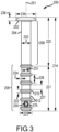
- FIGS 2 and 3 show an example implant device 200 of a design as described in International Patent Application Publication No. WO 2017/132573 A1 .
- the implant device 200 includes a head 202 and a conduit 204.
- the conduit 204 includes a first longitudinal portion 206 and a second longitudinal portion 208 disposed distal of the first longitudinal portion 206.
- the first longitudinal portion 206 includes a smooth exterior surface and second longitudinal portion 208 includes an anchoring surface feature including anchoring protrusions in the form of spaced circumferential ridges 210 and recess areas 212 between the ridges 210.
- one or more of the ridges 210 may be located in the vicinity of the paranasal sinus bone wall that is penetrated by the implant device 200 when implanted, preferably with one or more of the anchor protrusions disposed on each side of the bone, and more preferably with the wall of the sinus cavity bone penetrated by the implant device 200 disposed between two adjacent ones of the ridges 210.
- the implant device 200 includes an internal passage 238 extending between the proximal end 216 and the distal end 218, passing through the head 202 and the full length of the conduit 204.
- the internal passage 238 is open at the proximal end 216 for fluid communication with the lacrimal apparatus in the orbit when implanted and is open at the distal end 218 for fluid communication with a paranasal sinus when implanted, whereby the implant device 200 when implanted provides a fluid communication path between the lacrimal apparatus in the orbit and the paranasal sinus.
- the implant device 200 Disposed between the most distal pair of adjacent ridges 210, the implant device 200 includes two side ports 250 disposed on opposite sides of a longitudinal axis 251 of the implant device 200, and which side ports are designed to be disposed in the paranasal sinus when the implant device 200 is implanted.
- the implant device 200 includes a length 214 measured longitudinally between the proximal end 216 and the distal end.
- the circumferential ridges 210 have a width 222 at the base of the ridges 210 and a height 224 above adjacent recess areas 212.
- the ridges 210 are spaced on a center-to-center spacing 226, with inter-ridge spacing 227 between adjacent bases of adjacent ridges 210.
- the conduit 204 has a maximum exterior width 228 corresponding with the tops of the ridges 210, equal to the diameter of the circle of the cross-section through the conduit 204 at the top of the ridges 210.
- the conduit 204 has a minimum exterior width 231 at locations corresponding with the recess areas 212 on the second longitudinal portion 208 of the conduit 204.
- the head 202 has a circular perimeter having a diameter 234 and a depth 236.
- the beginning, or proximal end, of the second longitudinal portion 208 is located at a distance 220 from the proximal end 216, at the base of the ridge 210 nearest to the proximal end 216 and the second longitudinal portion 208 has a length 221.
- the internal passage 238 has a circular cross-section along the length of the implant device 200, which is of constant diameter except that the diameter of the internal passage flares to a larger diameter in transition portions adjacent the proximal end 216 and the distal end 218, which are further described below.
- Table 1 Dimension of Implant Device 200 Specific Example 214 17.8 mm 220 8mm 221 8.9 mm 222 0.44 mm 224 0.3 mm 226 1.65mm 227 1.21mm 228 2.41 mm 230 2 mm 231 1.8 mm 234 4 mm 236 0.9 mm
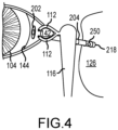
- Figure 4 shows an example of implant placement of the implant device 200 in an implantation position to fluid connect the lacrimal apparatus in the orbit with the ethmoid sinus.
- the head 202 and proximal end 216 are disposed in the lacrimal apparatus in the orbit in the conjunctival sac and the distal end 218 is disposed in the ethmoid sinus 126, with the conduit 204 passing through the surgical path across tissue including conjunctiva and a wall of the ethmoid bone in which the ethmoid sinus 126 is located, with some anchor ridges 210 disposed within the surgical path to engage tissue and help anchor the implant device 200, and with other ones of the anchor ridges 210 and the side ports 250 disposed in the ethmoid sinus.
- the surgical path from the lacrimal apparatus in the orbit may pass directly through the lacrimal caruncle 142, and in the implantation position the head 202 may be disposed over and engage tissue of the lacrimal carun
- the implant device may be used to provide access to the paranasal sinus to perform medical procedures or treatments directed to the paranasal sinus, for example to administer a treatment composition (also referred to as a treatment formulation) the paranasal sinus or to aspirate fluid from the paranasal sinus.
- a treatment composition also referred to as a treatment formulation
- Such a treatment formulation may include one or more drugs for treatment of sinusitis or may be an irrigation fluid to irrigate the paranasal sinus.
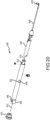
- paranasal sinus fluid access implantation tool 300 and various components of and example implantation procedures involving the implantation tool 300 will be described.
- the implantation tool 300 is shown in an implantation assembly with or being operated in connection with implantation of the example paranasal sinus fluid access implant device 200 shown in Figures 2-4 .
- the implantation tool 300 includes an insertion portion 302 configured to carry the implant device 200 for insertion through a surgical path between the lacrimal apparatus in the orbit and a paranasal sinus during an implantation procedure.
- the implantation tool 300 also includes a handle portion 304 configured to remain outside of the surgical path during the implantation procedure and which is manipulable by a medical practitioner to direct implantation of the implant device 200 during the implantation procedure.
- the insertion portion 302 includes a carrier member 306 on which the implant device 200 may be mounted to be carried to an implantation position through the surgical path from an approach through the palpebral fissure during an implantation procedure.
- the carrier member 306 includes a mounting portion 308.
- the mounting portion 308 is a longitudinal portion of the carrier member 306 on which the implant device 200 is secured to be carried by the carrier member 306 during an implantation procedure. As illustrated in Figures 5 and 7 , the mounting portion 308 of the carrier member 306 corresponds with the length of the carrier member 306 along which the implant device 200 is secured to be carried by the implantation tool 300 during an implantation procedure. In this regard, a distal end of the mounting portion 308 may correspond with the distal end 218 of the implant device 200 and the proximal end of the mounting portion 308 may correspond with the proximal end 216 of the implant device 200 as the implant device 200 is secured to the carrier member 306 for an implantation procedure.
- the implant device 200 is mounted on and secured to such a mounting portion 308 of the carrier member 306 in preparation for an implantation procedure, when the implant device 200 is inserted on the carrier member 306 into the surgical passage during an implantation procedure, the implant device 200 may deform or shift somewhat relative to the carrier member 306, which may include a movement of some portion or portions of the implant device 200 along the carrier member 306 outside of the mounting portion 308, on which the implant device 200 was initially confined as initially mounted. For instance, with the implantation tool 300, only a distal portion the implant device 200 is secured to the carrier member 306, so that portions of the implant device 200 located proximal to the locations of securement will be in tension as the implant device 200 is inserted into and advanced through the surgical path for implant placement.
- the implant device 200 may stretch out and elongate along the carrier member 306 proximal of the securement locations, and proximal portions of the stretched implant device 200 may extend proximal of the mounting portion 308 of the carrier member 306.
- the secured distal portion of the implant device 200 may deform and shift position slightly around the locations of securement, which may slightly shift the positioning of the distal end 218 of the implant device 200 relative to the distal end of the mounting portion 308 of the carrier member 306.
- a slidable member 310 is disposed mostly in internal working space housed within the handle portion 304 and the carrier member 306.
- the slidable member 310 is slidable along a translation path within the internal working space, and a spring 312 may provide a force to propel the slidable member 310 to release the implant device 200 from securement to the carrier member 306 to deploy the implant device 200 for implantation after the implant device 200 has been advanced in a surgical path to an implantation position.
- the slidable member 310 includes a first portion 314 in the form of an elongated conduit (e.g., hypodermic tube, also referred to as a hypo tube).
- the slidable member also includes a second portion 316 to interact with the spring 312 and has a depressable member 318 that may be depressed by a medical professional during an implantation procedure to release the spring 312 from a charged state (pre-compressed state) to propel the slidable member 310 toward a proximal end 320 of the implantation tool 300 to retract the slidable member 310 within the internal working space to release the implant device 200 from securement to the carrier member 306 for implantation deployment.
- the depressable member 318 interfaces with an actuation member in the form of an actuation button 322, which may be pushed by a medical professional to depress the depressable member 318 to actuate release of the implant device 200 from securement to the carrier member 306 during an implantation procedure.
- the first portion 314 of the slidable member 310 may be in the form of a small diameter hypo tube (e.g., of stainless steel) and the second portion 316 of the slidable member 310 may be a plastic structure (e.g., of polypropylene) molded over the hypo tube.
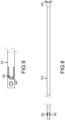
- Figure 8 illustrates the first portion 314 of the slidable member 310 in the form of a hypo tube with a flared proximal end 324 for more secure engagement with the over-molded second portion 316 of the slidable member 310, as illustrated in Figures 10 and 11 .
- the second portion 316 of the slidable member 310 includes retaining projections 326 to engage and retain the spring 312 relative to the slidable member 310.
- the actuation button 322 is part of a molded handle body piece (e.g., of polypropylene). In a compressed state, a distal end of the spring 312 is disposed against a shoulder feature 328 in the handle body.
- the implantation tool 300 includes a lumen provided through the first portion 314 of the slidable member 310 for passage of a guide wire therethrough to guide a distal end of the implantation tool 300 to the surgical path during an implantation procedure.
- the lumen is accessible from the proximal end 320 of the implantation tool 300 through an opening 330 though an end-cap insert 332 with tab portions 331 that lock into a proximal portion of an opening feature 333 in the handle body.
- the end-cap insert 332 encloses the internal working space adjacent the proximal end 320 and acts as a stop for movement of the slidable member 310 when propelled toward the proximal end 320 when the spring 312 in a compressed state is released by depression of the depressable member 318 through manipulation of the actuation button 322.
- a key feature of the implantation tool 300 is a securement mechanism provided to secure the implant device 200 in an implantation orientation on the carrier member 306 to carry the implant device 200 to an implantation position through the surgical path during an implantation procedure.
- the securement mechanism is reconfigurable from a securement configuration to secure the implant device 200 to the carrier member 306 to a released configuration to release the implant device 200 from securement to the carrier member 306 after being advanced through a surgical path to an implantation position, permitting withdrawal of the implantation tool 300, and the carrier member 306, to disengage the carrier member 306 from the positioned implant device 200 to leave the implant device 200 in place for implantation.
- the securement mechanism includes two securement members in the form of sheath members 340 that are integral with and provided as extensions at a distal end of the carrier member 306.
- the carrier member 306 may be made of a polymeric composition with material properties permitting the integral sheath members 340 to be sufficiently ductile to be routed through the distally-located side ports 250 of the implant device 200 from inside of to outside of the side ports 250 and then distally over distal portions of the exterior of the implant device 200 to engage and be retained in a secured configuration by retainment structure features provided on distal end portions of the slidable members 310.
- a distal end portion of the slidable member 310 includes securement tabs 342 cut into the wall of opposing sides of the distal end portion of the first portion 314 of the slidable member 310.
- Each of the securement tabs 342 is defined by a slot 344 cut through the wall of the first portion 314 of the slidable member 310 so that each securement tab 342 is configured be received through a corresponding opening 346 through a corresponding distal end portion of a sheath member 340 for securement of a sheath members 340 to the distal end portion of the slidable member 310.
- each sheath member 340 This permits the distal end portion of each sheath member 340 to be hooked over a corresponding securement tab 342 with the securement tab 342 projecting through the opening 346 of the sheath member 340 to hold the sheath member 340 secured in place in a securement configuration for advancement of the implant device 200 mounted on the carrier member 306 into and through a surgical route during an implantation procedure.
- An example of the engagement between the sheath members 340 and corresponding ones of the securement tabs 342 projecting through the openings 346 in an implantation assembly reading for an implantation procedure is illustrated for example, in Figure 16 .
- the secured sheath members 340 in the securement configuration engaged with the securement tabs 342 both secure the implant device 200 in an implantation orientation mounted on the carrier member 306 and provide a sheath-like protection of distal end portions of the implant device 200 that are covered by the sheath members 340, facilitating insertion of the implant device 200 into a surgical path and advancing the implant device 200 through the surgical path to an implantation position with reduced resistance to advancement from the distal end edge of the implant device 200.
- Securement of the implant device 200 to the carrier member 306 only at locations at and distal to the side ports 250 results in a majority of the length of the implant device 200 located proximal to the side ports 250 that is advanced into and through the surgical path to be advanced in a state of tension as a result of resistance to advancement from tissue in the surgical path pulling on the exterior of the conduit 204 of the implant device 200 when the implant device 200 is advanced through the surgical path, until the head 202 of the implant device 200 engages conjunctival tissue adjacent to the proximal opening of the surgical path when the implant device 200 has been fully advanced to an implantation position.
- the mounting portion 308 of the carrier member 306 extends to the distal end of the implant device 200, with a distal end portion of the carrier member 306 extending along an exterior of the implant device 200 to the distal end of the implant device 200.
- the securement members in the form of the sheath members 340 are integral portions of the carrier member 306, which together with the distal end portion of the slidable member 310 including the tab portions 342 are part of a securement mechanism to secure the implant device in the implantation orientation on the carrier member 306.
- carrier member refers to a carrying structure, which may be a combination of pieces or parts that during an implantation procedure provide the carrying function with the implant device mounted in a supported manner for advancing the implant device to an implantation position relative to a surgical path during an implantation procedure.
- one or more sheath members may extend out of the end of the internal passage of an implant device and fold back over the distal end of the implant device to extend over an exterior of a distal end portion of the implant device.
- such a folded-over sheath member may be retained along a distal end portion of the implant device 200 by a snare-type structure, for example similar to as described below with respect to Figures 19-28 , or by retainment features on a slidable member disposed in the vicinity of the side ports 250 of the implant device 200.
- sheath members may be separate from a carrier member, and not an integral part of a carrier member.
- the implantation tool 300 includes a safety cover 350 attached to the handle body to cover the actuation button 322 to prevent hand access to the actuation button 322 to prevent premature release of the implant device 200 from securement to the carrier member 306 during an implantation procedure.
- the safety cover 350 may be selectively removed from the handle body by pulling up on the safety cover 350, thereby permitting hand access to the actuation button 322 to permit a medical practitioner to press the actuation button 322 to depress the depressable member 318 and to disengage a proximal projection 352 on the depressable member 318 from a corresponding recess feature in the handle body, as seen best in Figure 7 .
- the depressable member 318 is in a locked configuration maintaining the spring 312 in a compressed state.
- the actuation button 322 is pushed down after removal from of the safety cover 350, the projection 352 is moved out of the locked configuration to permit expansion of the spring 312 from the compressed state to propel the slidable member 310 toward the proximal end 320 of the implantation tool 300, resulting in disengagement of the securement tabs 342 from the sheath members 340 to release the sheath members 340 from securing the implant device 200 to the carrier member 306.
- a distal portion of the slidable member 310 is retracted into the interior working space within the carrier member 306, for example as illustrated in Figure 17 .
- Figure 13 illustrates an implantation assembly ready for performing an implantation procedure with the implant device 200 mounted in an implantation orientation and secured to the carrier member 306.
- Figure 16 illustrates a distal portion of the implantation tool 300 with the implant device 200 secured to the carrier member 306 by the sheath members 340 engaged with the securement tabs 342 on the first portion 314 of the slidable member 310, with the securement tabs 342 received through the openings 346 and the corresponding sheath members 340.
- the securement tabs 342 may be slightly flared outward to enhance performance of the securement tabs 342 both for securing the sheath members 344 insertion into the surgical path and for release of the sheath members 340 when the tool member slidable member 310 is retracted to disengage from the sheath members 340 and to release the implant device 200 from securement to the carrier member 306.
- Figure 14 illustrates actuation of the implantation tool 300 to reconfigure the securement mechanism from the securement configuration to the released configuration during an implantation procedure after the implant device 200 has been advanced into a surgical path to an implantation position with the distal end 218 disposed in a paranasal sinus (e.g., ethmoid sinus, maxillary sinus or frontal sinus) and with the proximal end 216 disposed in the lacrimal apparatus in the orbit, and preferably with a distal side of the head 202 in contact with conjunctival tissue in the orbit.
- a paranasal sinus e.g., ethmoid sinus, maxillary sinus or frontal sinus
- Such an implantation position for the implant device 200 may be as illustrated for example in Figure 4 , but with the implant device 200 still secured to the carrier member 306 of the implantation tool 300.
- the safety cover 350 may be removed to permit access to the actuation button 322, which may be pushed to reconfigure the securement mechanism of the implantation tool 300 to the released configuration in which the implant device 200 is released from securement to the carrier member 306, as illustrated in Figure 17 .
- a medical professional performing an implantation procedure may pull back on the handle portion 304 to withdraw the carrier member 306 from the surgical path to leave the implant device 200 in place implanted in the implantation position to fluidly connect a paranasal sinus with the lacrimal apparatus in the orbit, as shown in Figure 15 .
- the distal portions of the sheath members 340 are retracted through the side ports 250 of the implant device 200 leaving the implant device 200 implanted in the implantation position completely disengaged from the implantation tool 300, as shown in Figure 15 and 18 , which may be in the implantation position as illustrated in Figure 4 .
- the carrier member 306 of the implantation tool 300 may be made of a uniform material of construction throughout, or may be made of a first material of construction (e.g., metallic or hard engineering plastic material) with higher rigidity to carry the implant device 200 and a second material of construction for the sheath members 340 with a lower rigidity that is sufficiently malleable to be readily deformed to be passed through the side ports 250 and to engage with the securement tabs 342.
- a first material of construction e.g., metallic or hard engineering plastic material
- the entire carrier member 306, including the integral sheath members 340 may be made of a uniform material with properties advantageously selected for performance of both the sheath members 342 and other portions of the carrier member 306 to carry the implant device during an implantation procedure.
- Some example materials that may be used as a single material of construction for the carrier member 306, including the integral sheath members 342, or that may be used for only the sheath members 340, include polyimide, polyamide (e.g., nylon), Mylar, PET (polyethylene terephthalate), FEP (fluorinated ethylene propylene), PTFE (polytetrafluoroethylene), nitinol suture, PVF (polyvinyl fluoride), composite polymer and silicone composite compositions.
- compositions are polymeric compositions, such as polyimide, polyamide (e.g., nylon), Mylar, PET (polyethylene terephthalate), FEP (fluorinated ethylene propylene) and PTFE (polytetrafluoroethylene) compositions, with polyamide (e.g., nylon) compositions more preferred for some implementations.
- polyamide e.g., nylon
- particularly preferred materials of construction for the carrier member 306, including the integral sheath members 342 are thermoplastic elastomers, and preferably polyether block amide elastomers (PEBAs).
- Polymeric compositions, or polymeric matrix for composites with a polymeric matrix, for the carrier member, and preferably for PEBA materials, with or without integral sheath members may in some implementations have a Shore D hardness in a range of 50 to 100, preferably 60-90 and more preferably 60-80.
- One useful group of such PEBA materials are the Pebax ® compositions from Arkema, and preferably some of the harder Pebax ® materials (e.g., with a Shore D hardness of 60 or larger).
- some Pebax ® compositions have a Shore D hardness of around 72 and are especially useful.
- Another useful group of such thermoplastic elastomers are the Vestamid ® E compositions from Evonik, and preferably some of the harder such materials (e.g., having a Shore D hardness of 60 or larger).
- paranasal sinus fluid access implantation tool 400 and various components of an example implantation procedures involving the implantation tool 400 will be described.
- the implantation tool 400 is described for mounting and implanting the example paranasal sinus fluid access implant device 200 shown in Figures 2-4 .
- the implantation tool 400 includes an insertion portion 402 configured to carry the implant device 200 for insertion through a surgical path between the lacrimal apparatus in the orbit and a paranasal sinus during an implantation procedure.
- the implantation tool 400 also includes a handle portion 404 configured to remain outside of the surgical path during the implantation procedure in which is manipulable by a medical practitioner to direct implantation of the implant device 200 during the implantation procedure.
- the insertion portion 402 includes a carrier member 406 on which the implant device 200 may be mounted to be carried to an implantation position through the surgical path with an approach through the palpebral fissure during an implantation procedure.
- the carrier member 406 includes a mounting portion 408, which is a longitudinal portion of the carrier member 406 on which the implant device 200 is secured to be carried by the carrier member 406 during an implantation procedure.
- the mounting portion 408 generally corresponds with the length of the carrier member 406 along which the implant device 200 is secured to be carried by the implantation tool 400 during an implantation procedure.
- a distal end of the mounting portion 408 may correspond with the distal end 218 of the mounted implant device 200 and the proximal end of the mounting portion 408 may correspond with the proximal end 216 of the mounted implant device 200.
- the implant device 200 is mounted on and secured to such a mounting portion 408 of the carrier member 406 in preparation for an implantation procedure, when the implant device 200 is inserted on the carrier member 406 into a surgical passage during an implantation procedure, the implant device 200 may deform or shift somewhat relative to the carrier member 406, including possibly moving somewhat outside of the mounting portion 408 on which the implant device 200 was initially confined as initially mounted.
- a handle body of the handle portion 404 and the carrier member 406 provide a housing for internal components disposed in internal space within the implantation tool 400.
- a slidable release member 410 is disposed in the internal working space within the handle portion 404 and the carrier member 406. The release member 410 is slidable along a translation path within the internal working space.
- the release member 410 is connected with a release pin 412 that is engaged with and retains a release spring 414.
- a proximal end of the release pin 412 is threaded into an end piece 416 located adjacent a proximal end 417 of the implantation tool.
- the end piece 416 is selectively manipulable by a medical professional during an implantation procedure to reconfigure a securement mechanism of the implantation tool 400 from a securement configuration to a released configuration to release the implant device 200 from securement to the carrier member 408 to permit the implantation tool 400 and the carrier member 406 to be withdrawn and disengaged from the implant device 200 to leave the implant device 200 implanted in an implantation position.
- the implantation tool 400 includes a securement member in the form of a snare member 418 and an alignment member 420 to assist in properly positioning and aligning the implant device 200 adjacent to the mounting portion 408 of the mounting member 406 with a distal end portion of the implant device 200 disposed through a snare loop formed by the snare member 418 for securing the implant device 200 to the carrier member 406 in the secured configuration.
- the snare member 418 is configured to be retractable to retract the snare loop about a distal portion of the implant device 200 disposed along the mounting portion 408 of the carrier member 406 to secure the implant device 200 to the carrier member 406.
- the implantation tool 400 also includes a guide loop member 422 that provides a small diameter loop near a distal end 424 of the implantation tool 400 for receiving a guide wire therethrough to guide the distal and 424 of the implantation tool 400 to a surgical path during an implantation procedure.
- the interior working space of the carrier member 406 is enclosed at a distal end of the carrier member 406 by a spherical end piece 426.
- the carrier member 406 may, for example, be in the form of a metallic hypo tube (e.g., stainless steel hypo tube) with a small diameter metallic ball (e.g., stainless steel bearing ball) for the spherical end piece 426 attached to and enclosing a distal end of the hypo tube.
- the carrier member 406 includes five side apertures disposed toward the distal end 424. Two apertures 428 on opposing sides of the carrier member 406 provide passages for the guide loop member to exit from the interior working space of the carrier member 406. From the apertures 428 the guide loop member 422 may extend in a proximal direction through the interior working space of the carrier member 406 and may be connected to the handle transition piece 436 at a distal end of the handle portion 404 to retain the guide member loop 422 in a fixed orientation with a desired small diameter loop open to receive a guide wire for guiding the carrier member 406 to a proximal end of the surgical path during an implantation procedure. An aperture 430 provides a passage for the alignment member to exit the interior working space of the carrier member 406.
- the alignment member 420 may extend in a proximal direction through the interior working space of the carrier member 406 and may be connected to a slidable loading member 438 disposed in the interior working space within the handle portion 404.
- Apertures 432 and 434 provide passages for the snare member to exit the interior working space of the carrier member 406.
- a first portion of the snare member 418 may extend in a proximal direction through the interior working space of the carrier member 406 and may be connected with the loading member 438.
- a second portion of the snare member 418 may be disposed in the interior working space of the carrier member 406 with an engagement portion of the snare member 418 in the form of an end loop 440 retained in the interior working space by a distal end portion of the release member 410 disposed through the end loop 440 when the snare member 418 is in the securement configuration to secure the implant device 200 to an exterior of the carrier member 406.
- the release member 410 disposed through the loop end 440 maintains the loop member 418 with a snare loop adjacent an exterior of the carrier member 406 extending between the aperture 432 and the aperture 434. However, in the released configuration, the release member 410 is retracted to disengage from the loop end 440 of the loop member 418 to release the snare loop and accordingly to release the implant device 200 from securement to the carrier member 406.
- the snare member 418 may be disposed in three different configurations, referred to as a loading configuration, a securement configuration and a released configuration, respectively.
- the release pin 410 is disposed through the loop end 440 of the snare member 418 to maintain the snare member 418 with a snare loop extending between the aperture 432 and the aperture 434.
- the loading member 438 is in a forward position, as illustrated in Figures 22 and 23 , and accordingly the end of the snare loop 418 connected to the loading member 438 is also in a forward position and the snare loop is in an expanded position to receive the implant device 200 to be secured to the mounting portion 408 of the carrier member 406.
- the implant device 200 may be guided to the proper position for securement to the carrier member 406 by inserting the alignment member 420 into the internal passage from the distal end 218 of the implant device 200 and sliding the implant device 200 over the alignment member 420 until the distal end 218 of the implant device 200 is stopped adjacent the aperture 434 by a bend portion of the alignment member 420 where the alignment member 420 exits the aperture 430. As fully advanced along the alignment member 420, a distal end portion of the implant device 200 will be disposed through and distal of the snare loop of the snare member 418.
- the snare member 418 may be repositioned to the securement configuration by a medical professional by retracting the loading member 438 along a translation path in the interior working space of the handle portion, resulting in retraction of the end of the snare member 418 connected to the loading member 438 to retract the snare loop of the snare member 418 to a retracted position around the distal end portion of the implant device 200 disposed through the snare loop 418.
- the snare loop closes around the exterior of the implant device 200 and collapses the internal passage through the implant device 200 at the retracted snare loop location to firmly secure the implant device 200 to the mounting portion 408 of the carrier member 406.
- the mounted implant device 200 is in the absence of the carrier member 406 disposed through the internal passage of the implant device 200 secured to the carrier member 406.
- a medical professional may pull back on an actuation projection in the form of a knob member 446 connected with the loading member 438 with a portion of the knob member 446 disposed through and guided by a longitudinal portion of a slot track formed in a wall of a handle body providing a housing for components in the interior working space of the handle portion 404.
- the loading member 438 compresses a loading spring 450 within the interior working space in the handle portion 404.
- the knob member 446 When the knob member 446 has been pulled fully back to a retracted position at the end of the longitudinal portion of the slot track 448, the knob member may be translated in a transverse direction into a side portion 452 of the slot track 448 to lock the knob member 446 and the loading member 438 in a retracted position held securely in place by the force exerted by the compressed loading spring 450, thereby also maintaining the snare loop of the snare member 418 in the retracted position of the securement configuration.
- the alignment member 420 is also connected to the loading member 438, as the loading member 438 is retracted, the alignment member 420 is also retracted with at least a portion of the alignment member being pulled into the interior working space of the carrier member 406, and including retracting into the interior working space a bend portion of the alignment member 420 that will make it easier for the alignment member 422 disengage from the implant device 200 during an implantation procedure after the implant device 200 has been released from securement to the carrier member 406.
- the alignment member may be made for example of a shape memory material, such as a nitinol material (nickel-titanium alloy), with shape memory for the bend portion.
- the snare member 418 may also be made of such a shape memory material with shape memory for the snare loop.
- Figures 26-28 more particularly illustrate the process of mounting the implant device 200 on the mounting portion 408 of the carrier member 406.
- Figure 26 shows the implantation tool 400 in the loading configuration ready to receive the implant device 200 for mounting.
- Figure 27 shows sliding the implant device 200 over the alignment member 420 toward the snare loop of the snare member 418.
- Figure 28 shows the implant device 200 fully advanced over the alignment member 420 into an implantation orientation for mounting on the mounting portion 408 of the carrier member 406.
- the knob member may be retracted along the longitudinal portion of the slot track 448 to retract the snare loop of the snare member 418 around a location on the distal end portion of the implant device 200 in the securement configuration.
- the snare loop secures the implant device 200 to the carrier member at a securement location along the distal end portion of the implant device 200 that corresponds with a recess area 212 between anchor ridges 210, and preferably corresponds with the recess area 212 between the most distal pair of adjacent anchor ridges 210 (between which the side ports 250 are positioned in the example implant device 200).
- the knob member may be translated to the side into the side portion 452 of the slot track 448 to lock the snare member 418 in the securement configuration.
- the carrier member 406 and the implant device 200 secured thereto may be advanced into a surgical path during an implantation procedure until the implant device 200 is advanced to an implantation position, preferably with the head 202 of the implant device 200 engaging tissue in the lacrimal apparatus in the orbit adjacent a proximal end of the surgical path.
- the snare loop of the snare member 418 may be released to the released configuration for implantation of the implant device 200.
- the release member 410 may be retracted along a translation path within the interior working space of the implantation tool 400 by a medical professional pulling back on the end piece 416 to retract the release pin 412 and the release member 410 connected to the release pin 412, and to disengage the distal end portion of the release member 410 from the loop end 440 of the snare member 418.
- the loop end 440 of the snare member 418 is released, the loop end 440 is no longer secured in the interior working space within the carrier member 406 and the snare loop is released, releasing the implant device 200 from securement to the carrier member 406, and permitting the implantation tool 400, and accordingly the carrier member 406 to be withdrawn from a surgical path relative to the implant device 200 to leave the implant device 200 implanted in an implantation position through the surgical path to fluidly connect the lacrimal apparatus in the orbit with a paranasal sinus.
- the implantation tool 400 includes a lock member 454 that is normally maintained in a raised position as shown in Figures 19 , 21 and 22 by a lock spring 456. In the raised position, the lock member 454 engages the release pin 412 to maintain the release pin 412 in a locked position to prevent premature retraction of the release pin 412 and the release member 410. Prior to pulling back on the end piece 416 to retract the release pin 412, the medical professional would depress the lock member 454 to unlock the release pin 412, and while holding the lock member 454 in the depressed position would pull back on the end piece 416 to retract the release pin 412 and the release member 410.
- the release spring 414 may initially be in an uncharged state or, preferably, in a charged extension state with the release spring 414 biasing the release pin 412 and the release member 410 toward the proximal end 417 of the implantation tool 400 and urging the end piece 416 toward the release pin 412, such that when a medical professional pulls back on the end piece 416, the medical professional must pull with sufficient force to overcome the biasing force of the release spring 414.
- the release spring 414 and the loading spring 450 will be isolated from each other.
- an implantation tool with a snare-type securement structure of the type illustrated in Figures 19-28 may be adapted for mounting an implant device with the carrier member extending through the internal passage of the implant device and with a snare loop extending around at least circumferential portion of the exterior of the implant device, for example including alignment of snare exit apertures such as apertures 432 and 434 with features such as side ports 250 of the implant device 200.
Landscapes
- Health & Medical Sciences (AREA)
- Life Sciences & Earth Sciences (AREA)
- Surgery (AREA)
- Animal Behavior & Ethology (AREA)
- Public Health (AREA)
- Engineering & Computer Science (AREA)
- Biomedical Technology (AREA)
- Heart & Thoracic Surgery (AREA)
- Veterinary Medicine (AREA)
- General Health & Medical Sciences (AREA)
- Nuclear Medicine, Radiotherapy & Molecular Imaging (AREA)
- Ophthalmology & Optometry (AREA)
- Medical Informatics (AREA)
- Pathology (AREA)
- Molecular Biology (AREA)
- Otolaryngology (AREA)
- Anesthesiology (AREA)
- Hematology (AREA)
- Plastic & Reconstructive Surgery (AREA)
- Vascular Medicine (AREA)
- Prostheses (AREA)
- Surgical Instruments (AREA)
Description
- Millions of people are treated each year for infections of the paranasal sinuses, or sinusitis, with many of those suffering from chronic sinusitis. Conventional surgical interventions directed to providing enhanced irrigation and drainage may provide moderate symptomatic improvement but not a cure. Recent interventions have been proposed to directly access the paranasal sinuses to permit medical procedures or drug treatments to be performed more directly in the paranasal sinuses. Direct access to a paranasal sinus has been proposed from an approach through the nose and an ostium that provides a natural opening from the nasal cavity into a paranasal sinus. Such medical interventions to directly access a paranasal sinus through the natural opening of the ostium involve complex manipulations of access tools to and through the restricted space of the ostium.
- Another more recent intervention is based on providing an artificial fluid communication path between the lacrimal apparatus and a paranasal sinus through a paranasal sinus access implant device implanted through an artificially formed surgical path between the lacrimal apparatus in the paranasal sinus to provide direct fluid communication access from the lacrimal apparatus to the paranasal sinus through an internal passage of the implanted implant device. One surgical approach is through the palpebral fissure to form a surgical path between the lacrimal apparatus in the orbit and a paranasal sinus, often the ethmoid sinus. Examples of some paranasal sinus access implant devices and implantation tools and procedures for implanting such implant devices to provide a fluid communication between the lacrimal apparatus and a paranasal sinus are disclosed for example in
International Patent Application Publication Nos. WO 2012/048278 A2 ;WO 2013/154843 A1 ;WO 2014/116980 A1 ;WO 2015/069433 A1 ;WO 2016/014996 A1 ;WO 2016/015002 A1 ; andWO 2017/132573 A1 published by the World Intellectual Property Organization.WO 2014/116980 A1 discloses an implantation tool to implant a paranasal sinus fluid access implant device, the implantation tool comprising: a carrier member; a handle portion; and an internal working space housed within the handle portion and the carrier member.US 2005/0085891 A1 discloses a biliary stent delivery device comprising a securement mechanism and a release mechanism. - When implanted, such paranasal sinus access implant devices provide convenient access to the paranasal sinus for administration of drugs or irrigation fluid directly to the paranasal sinus or performance of medical procedures in the paranasal sinus. However, for enhanced compatibility and interaction with surgically-penetrated tissue, such paranasal sinus access implant devices may be made of relatively soft and flexible material, for example polymeric materials, such as medical grade silicone, having a Shore A hardness often in a range of about 60-80. Advancing such flexible implant devices through a properly sized surgical route, and without additional inflammation of tissue in and adjacent to the surgical path, can be difficult. Such implant devices may include anchor protrusions configured to interact with issue exposed in the surgical path to help anchor the implanted implant device. For enhanced fit through and retention in the surgical path, the outside diameter of the implant device may be larger than the diameter of the surgical cut made to form the surgical path, especially at locations of the anchor protrusions. Resistance to insertion through the surgical path when an implant device is advanced into and through the surgical path during an implantation procedure may result in accordion-like deformation of the flexible implant device that further increases resistance to advancement of the implant device and complicating performance of the implantation procedure and increasing potential for additional inflammation of tissue that can lead to patient discomfort and longer heal times. Additionally, the wall of the sinus bone that is penetrated by the surgical cut to access the paranasal sinus may be very thin and susceptible to fracture and breakage during the implantation procedure. Such fracturing and breakage of the wall of the sinus bone may be detrimental to good securement of the implanted device in the implantation position through the surgical cut, and is also not desired for good surgical practice.
- Although surgical implantation techniques for implantation of such paranasal sinus access implant devices to fluidly connect the lacrimal apparatus in the orbit and a paranasal sinus have achieved a significant level of success in accessing and treating conditions of the paranasal sinuses, implantation tools and procedures still may suffer from one or more of these problems, and there is a significant need for improved implantation tools and procedures to further address such problems.
- The inventors have inventively recognized that these problems may be addressed at least in part for implantation of paranasal sinus access implant devices of the type summarized above implanted with a surgical approach through the palpebral fissure to provide an artificial fluid communication connection between the lacrimal apparatus in the orbit and a paranasal sinus by providing implantation tools and implantation procedures that maintain the paranasal access implant device mostly in tension as the implant device is advanced from the palpebral fissure approach through the surgical path during implantation procedure. Stated another way, when most of the length of the implant device that is advanced through the surgical path is pulled through the surgical path (in tension) rather than being pushed through the surgical path (in compression), the implant device is allowed to stretch out rather than bunch up in an accordion-like fashion during advancement into and through the surgical path, which eases advancement of the implant device through the surgical path and tends to reduce potential for causing fracture or breakage of the sinus wall bone, other tissue inflammation and the difficulty for the medical professional to perform the implantation procedure. A result may be both that the implantation procedure is faster and easier for a medical professional to perform and with reduced potential for surgical complications.
- A first aspect of this disclosure provides an implantation tool to implant a paranasal sinus fluid access implant device with an internal fluid communication passage through an artificial, surgical path between a lacrimal apparatus in the orbit and a paranasal sinus in an implantation procedure to provide direct fluid communication access through the internal passage from the lacrimal apparatus in the orbit to the paranasal sinus. This implantation tool, which is the implantation tool according to the invention, comprises:
- a carrier member configured to carry the implant device on a mounting portion of the carrier member in a mounted orientation to position the implant device in an implantation position through the surgical path from an approach through the palpebral fissure during the implantation procedure;
- a securement mechanism to secure the implant device in the implantation orientation on the carrier member to carry the implant device to the implantation position during the implantation procedure, the securement mechanism being reconfigurable from a securement configuration to secure the implant device to the mounting portion of the carrier member in the implantation orientation to a released configuration to release the implant device from securement to the carrier member to permit withdrawal of the carrier member relative to the implant device to leave the implant device implanted in the implantation position during the implantation procedure, wherein the securement mechanism comprises at least one securement member positioned to extend over and press against an exterior portion of the implant device in the implantation orientation when the securement mechanism is in the securement configuration;
- a handle portion connected with the carrier member and configured to remain outside of the surgical path during the implantation procedure and being manipulable by a medical practitioner to direct implantation of the implant device during the implantation procedure;
- internal working space housed within at least a portion of the handle portion and at least a portion of the carrier member;
- a release mechanism disposed at least in part in the internal working space and manipulable to reconfigure the securement mechanism from the securement configuration to the released configuration.
- A second aspect of this disclosure provides an implantation assembly for implanting a paranasal sinus fluid access implant device through a surgical path between a lacrimal apparatus in the orbit and a paranasal sinus in an implantation procedure to provide direct fluid communication access from the lacrimal apparatus in the orbit to the paranasal sinus through an internal passage of the implant device. The implantation assembly of this second aspect may include:
- such a paranasal sinus access implant device: and
- an implantation tool, wherein the implant device is mounted in a mounting orientation on a mounting portion of a carrier member of the implantation tool with a securement mechanism of the implantation tool in a securement configuration, and which securement mechanism is reconfigurable to a released configuration to release the implant device from securement to the mounting portion of the carrier member.
- A third aspect of this disclosure provides an implantation kit for implanting a paranasal sinus fluid access implant device through a surgical path between a lacrimal apparatus in the orbit and a paranasal sinus in an implantation procedure to provide direct fluid communication access from the lacrimal apparatus in the orbit to the paranasal sinus through an internal passage of the implant device. The implantation kit of this third aspect may include:
- an implantation tool, wherein the implant device is mountable in a mounting orientation on a mounting portion of a carrier member of the implantation tool with a securement mechanism of the implantation tool in a securement configuration, and which securement mechanism is reconfigurable to a released configuration to release the implant device from securement to the mounting portion of the carrier member; and
- such a paranasal sinus access implant device;
- wherein, the implantation tool and implant device are assembled or assemblable into an implantation assembly with the implant device mounted in the mounting orientation on the mounting portion of the carrier member with the securement mechanism in the securement configuration.
- A fourth aspect of this disclosure provides a method for implanting a paranasal sinus access implant device to fluidly connect a lacrimal apparatus in the orbit with a paranasal sinus. The method of this fourth aspect may include:
- with a surgical approach through the palpebral fissure, surgically forming an artificial surgical path between a location in a lacrimal apparatus in the orbit and a paranasal sinus;
- advancing an implantation assembly including such a paranasal sinus access implant device from an approach through the palpebral fissure until the implant device extends through the surgical path in the implantation position, wherein the implantation assembly includes the implant device mounted in a mounting orientation on a mounting portion of a carrier member of an implantation tool with a securement mechanism of the implantation tool in a securement configuration, and which securement mechanism is reconfigurable to a released configuration to release the implant device from securement to the mounting portion of the carrier member;
- manipulating the release mechanism to reconfigure the securement mechanism from the securement configuration to the released configuration;
- withdrawing the implantation tool from the surgical path, leaving the implant device implanted through the surgical path fluidly connecting the lacrimal apparatus in the orbit with the paranasal sinus.
- The implantation tool used in the method of this fourth aspect may be according to the first aspect of this disclosure. The implantation assembly used in the method of this fourth aspect may be according to the second aspect of this disclosure. The implant device and the implantation tool used in the implantation assembly used in the method of this fourth aspect may be provided in an implantation kit according to the third aspect of this disclosure.
- A fifth aspect of this disclosure provides a method for implanting a paranasal sinus fluid access implant device through an artificial, surgical path between a lacrimal apparatus in the orbit and a paranasal sinus to provide direct fluid communication access from the lacrimal apparatus in the orbit to the paranasal sinus through an internal passage of the implant device. The method of this fifth aspect may include:
- with the implant device secured to an exterior of a carrier member of an implantation tool with a distal end of the implant device disposed toward a distal end of the implantation tool and a proximal end of the implant device disposed toward a proximal end of the implantation tool and with an implantation approach from the lacrimal apparatus in the orbit, advancing the implant device through the surgical path between the lacrimal apparatus in an orbit and the paranasal sinus until the implant device is in an implantation position with the distal end of the implant device disposed in the paranasal sinus and the proximal end of the implant device disposed in the lacrimal apparatus in the orbit;
- after the advancing, releasing the implant device from securement to the exterior of the carrier member and withdrawing the carrier member from the surgical path to leave the implant device implanted in the implantation position fluidly connecting the lacrimal apparatus in the orbit with the paranasal sinus through the internal passage of the implant device; and
- the implant device having a length from the proximal end to the distal end of the implant device;
- wherein during the advancing a length portion of the implant device, which is smaller than the length of the implant device, enters into and advances at least some distance through the surgical path, and a majority of the length portion is in tension while advancing through the surgical path.
- These and other aspects of this disclosure and features for use therewith are further described below. A number of feature refinements and additional features disclosed below are applicable to each of the aspects of this disclosure, including to an implantation tool, implantation assembly, implantation kit and an implantation method of any such aspect. These feature refinements and additional features may be used individually or in any combination in any or all of these aspects. As such, each of the features that will be discussed below may be, but are not required to be, used with any other feature or combination of features of the same or any other aspect of this disclosure.
- Numerous additional features and advantages of the present disclosure will become apparent to those skilled in the art upon consideration of the embodiment descriptions provided below.
-
-
Figure 1 is an illustration showing the lacrimal apparatus and some example routes for surgical paths between the lacrimal apparatus in the orbit and a paranasal sinus with a surgical approach through the palpebral fissure for implantation of an implant device to provide direct fluid communication access from the lacrimal apparatus in the orbit to the paranasal sinus. -
Figure 2 is a perspective view of an example embodiment of a paranasal sinus access implant device for implantation to provide direct fluid communication access from the lacrimal apparatus in the orbit to the paranasal sinus. -
Figure 3 is a side view of the paranasal sinus access implant device illustrated inFigure 2 . -
Figure 4 is an illustration showing an example embodiment of a paranasal sinus access implant device in an implantation position as implanted to provide direct fluid communication access from the lacrimal apparatus in the orbit to an ethmoid sinus. -
Figure 5 is a perspective view showing an implantation assembly including an example embodiment of an implantation tool in an implantation assembly combination with an example paranasal sinus access implant device to be implanted using the implantation tool to provide direct fluid communication access from the lacrimal apparatus in the orbit to the paranasal sinus. -
Figure 6 is an exploded view showing components of the implantation tool ofFigure 5 . -
Figure 7 is a sectional view taken along a section line along the length of the implantation tool ofFigure 5 in the implantation assembly configuration ofFigure 5 including the example paranasal sinus access implant device ofFigure 5 . -
Figure 8 is a side view of a first portion of a slidable member of the implantation tool ofFigure 5 . -
Figure 9 is a side view of a distal end portion of the first portion of the slidable member illustrated inFigure 8 . -
Figure 10 is a side view of the slidable member of the implantation tool ofFigure 5 . -
Figure 11 is an end view of the slidable member shown inFigure 10 . -
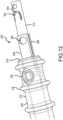
Figure 12 is a perspective view of a distal end portion of the tool assembly combination shown inFigure 5 . -
Figures 13-15 are perspective views illustrating use of the implantation tool shown inFigure 5 during an implantation procedure to implant the example embodiment of a paranasal sinus access implant device shown inFigure 5 . -
Figures 16-18 are partial sectional views illustrating a distal end portion of the implantation tool and the example embodiment of a paranasal sinus access implant device shown inFigure 5 during an implantation procedure. -
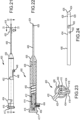
Figure 19 is a perspective view showing another example embodiment an implantation tool for use to implant a paranasal sinus access implant device to provide direct fluid communication access from the lacrimal apparatus in the orbit to the paranasal sinus. -
Figure 20 is an exploded view showing components of the implantation tool ofFigure 19 . -
Figure 21 is a top view of the implantation tool ofFigure 19 . -
Figure 22 is a sectional view of the implantation tool ofFigure 19 taken along a longitudinal section line as shown inFigure 21 . -
Figure 23 is a partial sectional view of the implantation tool ofFigure 19 taken along a transverse section line as shown inFigure 21 . -
Figure 24 is a partial side view of a distal end portion of a carrier member of the implantation tool ofFigure 19 . -
Figure 25 is a perspective view of a distal end portion of the implantation tool ofFigure 19 . -
Figures 26-28 are perspective views illustrating use of the implantation tool ofFigure 19 in for performing an implantation procedure. - The term "lacrimal apparatus" or "lacrimal system" refers to the collection of physiological components that accomplish the production and secretion of lacrimal fluid to lubricate the eyeball, containment of lacrimal fluid in a reservoir of lacrimal fluid in the orbit and drainage of lacrimal fluid from the orbit to the nasal cavity. The lacrimal apparatus includes the lacrimal glands, the tear drainage system and the reservoir of lacrimal fluid located between the lacrimal glands and the tear drainage system. The reservoir of lacrimal fluid includes the eyelid margins and the conjunctival sac (and including the pool of tears in the lower conjunctival cul-de-sac that is sometimes referred to as the lacrimal lake). The tear drainage system includes the puncta, canaliculi and nasolacrimal duct (including the so-called lacrimal sac located at the top of the nasolacrimal duct) through which excess tears drain to Hasner's valve and into the nasal cavity.
Figure 1 shows generally the lacrimal apparatus. Lacrimal fluid is produced and secreted fromlacrimal glands 102 to lubricate the surface of theeyeball 104 disposed within the orbit. Lacrimal fluid forms a coating over theeyeball 104 and is generally contained within the conjunctival sac (the space between thelower eyelid 106,upper eyelid 108 andeyeball 104 that is lined by the conjunctiva). Excess lacrimal fluid is conducted to the vicinity of the medial canthus (medial corner of the eye) and drains through thelacrimal puncta 110 into thelacrimal canaliculi 112 and into thelacrimal sac 114 of thenasolacrimal duct 116. The lacrimal fluid then drains from thenasolacrimal duct 116 through Hasner's valve and into the nasal cavity. - As used herein, a surgical path refers to an artificially-created passage prepared by surgical means from an approach through the palpebral fissure between the lacrimal apparatus in the orbit and a paranasal sinus for implantation therethrough of an implant device with an internal passage to provide direct fluid communication access from the lacrimal apparatus in the orbit to the paranasal sinus. As may be appreciated, the palpebral fissure is an anatomical opening between eyelids, also referred to as the rima palpebrarum. Such an implant device may, for example, be of a design as described in any of
U.S. Patent No. 9,308,358 U.S. Patent No. 9,561,350 U.S. Patent Application Publication No. 2017/0216094 A1 orInternational Patent Application Publication No. WO 2017/132573 A1 , each of which is incorporated by reference herein. - The paranasal sinuses include the frontal sinuses, maxillary sinuses, ethmoid sinuses and sphenoid sinuses, which are cavities contained within frontal, maxilla, ethmoid and sphenoid bones, respectively. The paranasal sinuses drain into the nasal cavity.
Figure 1 also shows the general proximity of thefrontal sinus 122,maxillary sinus 124 andethmoid sinus 126 relative to features of the lacrimal apparatus and some example routes for a surgical path are shown by dashed lines. Afirst example route 130 for a surgical path is from the lacrimal apparatus in the orbit to the frontal sinus. A second examplesurgical path route 132 is from the lacrimal apparatus in the orbit to theethmoid sinus 126. A third examplesurgical path route 134 is from the lacrimal apparatus in the orbit to themaxillary sinus 124. The example surgical path routes shown inFigure 1 are for purposes of general illustration only and not to show precise locations where a surgical path might be formed to connect a part of the lacrimal apparatus with the corresponding paranasal sinus. Although not shown inFigure 1 , another example route for a surgical path is from the lacrimal apparatus in the orbit to the sphenoid sinus. One more specific example of a preferred route for a surgical path to a paranasal sinus is for the surgical path to pass directly through the lacrimal caruncle and through tissue to the targeted paranasal sinus. Such a route for a surgical path benefits from relatively easy location of the surgical entry point by a medical professional performing an implantation procedure. -
Figures 2 and3 show anexample implant device 200 of a design as described inInternational Patent Application Publication No. WO 2017/132573 A1 . Theimplant device 200 includes ahead 202 and aconduit 204. Theconduit 204 includes a firstlongitudinal portion 206 and a secondlongitudinal portion 208 disposed distal of the firstlongitudinal portion 206. The firstlongitudinal portion 206 includes a smooth exterior surface and secondlongitudinal portion 208 includes an anchoring surface feature including anchoring protrusions in the form of spacedcircumferential ridges 210 andrecess areas 212 between theridges 210. When theimplant device 200 is implanted through a surgical path to fluidly connect the lacrimal apparatus in the orbit with a paranasal sinus, one or more of theridges 210 may be located in the vicinity of the paranasal sinus bone wall that is penetrated by theimplant device 200 when implanted, preferably with one or more of the anchor protrusions disposed on each side of the bone, and more preferably with the wall of the sinus cavity bone penetrated by theimplant device 200 disposed between two adjacent ones of theridges 210. Theimplant device 200 includes aninternal passage 238 extending between theproximal end 216 and thedistal end 218, passing through thehead 202 and the full length of theconduit 204. Theinternal passage 238 is open at theproximal end 216 for fluid communication with the lacrimal apparatus in the orbit when implanted and is open at thedistal end 218 for fluid communication with a paranasal sinus when implanted, whereby theimplant device 200 when implanted provides a fluid communication path between the lacrimal apparatus in the orbit and the paranasal sinus. Disposed between the most distal pair ofadjacent ridges 210, theimplant device 200 includes twoside ports 250 disposed on opposite sides of alongitudinal axis 251 of theimplant device 200, and which side ports are designed to be disposed in the paranasal sinus when theimplant device 200 is implanted. - Various dimensions are shown in
Figure 3 for theimplant device 200. Theimplant device 200 includes alength 214 measured longitudinally between theproximal end 216 and the distal end. Thecircumferential ridges 210 have a width 222 at the base of theridges 210 and aheight 224 aboveadjacent recess areas 212. Theridges 210 are spaced on a center-to-center spacing 226, withinter-ridge spacing 227 between adjacent bases ofadjacent ridges 210. Theconduit 204 has amaximum exterior width 228 corresponding with the tops of theridges 210, equal to the diameter of the circle of the cross-section through theconduit 204 at the top of theridges 210. Theconduit 204 has aminimum exterior width 231 at locations corresponding with therecess areas 212 on the secondlongitudinal portion 208 of theconduit 204. Thehead 202 has a circular perimeter having adiameter 234 and adepth 236. The beginning, or proximal end, of the secondlongitudinal portion 208 is located at adistance 220 from theproximal end 216, at the base of theridge 210 nearest to theproximal end 216 and the secondlongitudinal portion 208 has alength 221. Theinternal passage 238 has a circular cross-section along the length of theimplant device 200, which is of constant diameter except that the diameter of the internal passage flares to a larger diameter in transition portions adjacent theproximal end 216 and thedistal end 218, which are further described below. - Some example values for a number of the dimensions shown in
Figure 3 for one example embodiment of theimplant device 200 are summarized in Table 1.Table 1 Dimension of Implant Device 200Specific Example 214 17.8 mm 220 8mm 221 8.9 mm 222 0.44 mm 224 0.3 mm 226 1.65 mm 227 1.21 mm 228 2.41 mm 230 2 mm 231 1.8 mm 234 4 mm 236 0.9 mm - Further features of the
example implant device 200 are described inInternational Patent Application Publication No. WO 2017/132573 A1 . -
Figure 4 shows an example of implant placement of theimplant device 200 in an implantation position to fluid connect the lacrimal apparatus in the orbit with the ethmoid sinus. In the implantation position shown inFigure 4 , thehead 202 andproximal end 216 are disposed in the lacrimal apparatus in the orbit in the conjunctival sac and thedistal end 218 is disposed in theethmoid sinus 126, with theconduit 204 passing through the surgical path across tissue including conjunctiva and a wall of the ethmoid bone in which theethmoid sinus 126 is located, with someanchor ridges 210 disposed within the surgical path to engage tissue and help anchor theimplant device 200, and with other ones of theanchor ridges 210 and theside ports 250 disposed in the ethmoid sinus. In an alternative example, the surgical path from the lacrimal apparatus in the orbit may pass directly through thelacrimal caruncle 142, and in the implantation position thehead 202 may be disposed over and engage tissue of thelacrimal caruncle 142. - Whether the implanted implant design has a design of a type as illustrated in
Figures 2 and3 or a different design, after implantation, the implant device may be used to provide access to the paranasal sinus to perform medical procedures or treatments directed to the paranasal sinus, for example to administer a treatment composition (also referred to as a treatment formulation) the paranasal sinus or to aspirate fluid from the paranasal sinus. Such a treatment formulation may include one or more drugs for treatment of sinusitis or may be an irrigation fluid to irrigate the paranasal sinus. - With reference also to
Figures 5-18 , an embodiment of a paranasal sinus fluidaccess implantation tool 300 and various components of and example implantation procedures involving theimplantation tool 300 will be described. For illustration purposes, theimplantation tool 300 is shown in an implantation assembly with or being operated in connection with implantation of the example paranasal sinus fluidaccess implant device 200 shown inFigures 2-4 . - The
implantation tool 300 includes aninsertion portion 302 configured to carry theimplant device 200 for insertion through a surgical path between the lacrimal apparatus in the orbit and a paranasal sinus during an implantation procedure. Theimplantation tool 300 also includes ahandle portion 304 configured to remain outside of the surgical path during the implantation procedure and which is manipulable by a medical practitioner to direct implantation of theimplant device 200 during the implantation procedure. Theinsertion portion 302 includes acarrier member 306 on which theimplant device 200 may be mounted to be carried to an implantation position through the surgical path from an approach through the palpebral fissure during an implantation procedure. Thecarrier member 306 includes a mountingportion 308. The mountingportion 308 is a longitudinal portion of thecarrier member 306 on which theimplant device 200 is secured to be carried by thecarrier member 306 during an implantation procedure. As illustrated inFigures 5 and7 , the mountingportion 308 of thecarrier member 306 corresponds with the length of thecarrier member 306 along which theimplant device 200 is secured to be carried by theimplantation tool 300 during an implantation procedure. In this regard, a distal end of the mountingportion 308 may correspond with thedistal end 218 of theimplant device 200 and the proximal end of the mountingportion 308 may correspond with theproximal end 216 of theimplant device 200 as theimplant device 200 is secured to thecarrier member 306 for an implantation procedure. It is noted that although theimplant device 200 is mounted on and secured to such a mountingportion 308 of thecarrier member 306 in preparation for an implantation procedure, when theimplant device 200 is inserted on thecarrier member 306 into the surgical passage during an implantation procedure, theimplant device 200 may deform or shift somewhat relative to thecarrier member 306, which may include a movement of some portion or portions of theimplant device 200 along thecarrier member 306 outside of the mountingportion 308, on which theimplant device 200 was initially confined as initially mounted. For instance, with theimplantation tool 300, only a distal portion theimplant device 200 is secured to thecarrier member 306, so that portions of theimplant device 200 located proximal to the locations of securement will be in tension as theimplant device 200 is inserted into and advanced through the surgical path for implant placement. This advantageously permits theimplant device 200 to stretch out and elongate along thecarrier member 306 proximal of the securement locations, and proximal portions of the stretchedimplant device 200 may extend proximal of the mountingportion 308 of thecarrier member 306. Likewise, the secured distal portion of theimplant device 200 may deform and shift position slightly around the locations of securement, which may slightly shift the positioning of thedistal end 218 of theimplant device 200 relative to the distal end of the mountingportion 308 of thecarrier member 306. - As shown in
Figures 5-17 , aslidable member 310 is disposed mostly in internal working space housed within thehandle portion 304 and thecarrier member 306. Theslidable member 310 is slidable along a translation path within the internal working space, and aspring 312 may provide a force to propel theslidable member 310 to release theimplant device 200 from securement to thecarrier member 306 to deploy theimplant device 200 for implantation after theimplant device 200 has been advanced in a surgical path to an implantation position. As shown in the figures, theslidable member 310 includes afirst portion 314 in the form of an elongated conduit (e.g., hypodermic tube, also referred to as a hypo tube). The slidable member also includes asecond portion 316 to interact with thespring 312 and has adepressable member 318 that may be depressed by a medical professional during an implantation procedure to release thespring 312 from a charged state (pre-compressed state) to propel theslidable member 310 toward aproximal end 320 of theimplantation tool 300 to retract theslidable member 310 within the internal working space to release theimplant device 200 from securement to thecarrier member 306 for implantation deployment. Thedepressable member 318 interfaces with an actuation member in the form of anactuation button 322, which may be pushed by a medical professional to depress thedepressable member 318 to actuate release of theimplant device 200 from securement to thecarrier member 306 during an implantation procedure. By way of example, thefirst portion 314 of theslidable member 310 may be in the form of a small diameter hypo tube (e.g., of stainless steel) and thesecond portion 316 of theslidable member 310 may be a plastic structure (e.g., of polypropylene) molded over the hypo tube. -
Figure 8 illustrates thefirst portion 314 of theslidable member 310 in the form of a hypo tube with a flaredproximal end 324 for more secure engagement with the over-moldedsecond portion 316 of theslidable member 310, as illustrated inFigures 10 and 11 . Thesecond portion 316 of theslidable member 310 includes retainingprojections 326 to engage and retain thespring 312 relative to theslidable member 310. In the example of theimplantation tool 300, theactuation button 322 is part of a molded handle body piece (e.g., of polypropylene). In a compressed state, a distal end of thespring 312 is disposed against ashoulder feature 328 in the handle body. Theimplantation tool 300 includes a lumen provided through thefirst portion 314 of theslidable member 310 for passage of a guide wire therethrough to guide a distal end of theimplantation tool 300 to the surgical path during an implantation procedure. The lumen is accessible from theproximal end 320 of theimplantation tool 300 through anopening 330 though an end-cap insert 332 withtab portions 331 that lock into a proximal portion of anopening feature 333 in the handle body. The end-cap insert 332 encloses the internal working space adjacent theproximal end 320 and acts as a stop for movement of theslidable member 310 when propelled toward theproximal end 320 when thespring 312 in a compressed state is released by depression of thedepressable member 318 through manipulation of theactuation button 322. - A key feature of the
implantation tool 300 is a securement mechanism provided to secure theimplant device 200 in an implantation orientation on thecarrier member 306 to carry theimplant device 200 to an implantation position through the surgical path during an implantation procedure. The securement mechanism is reconfigurable from a securement configuration to secure theimplant device 200 to thecarrier member 306 to a released configuration to release theimplant device 200 from securement to thecarrier member 306 after being advanced through a surgical path to an implantation position, permitting withdrawal of theimplantation tool 300, and thecarrier member 306, to disengage thecarrier member 306 from the positionedimplant device 200 to leave theimplant device 200 in place for implantation. In the embodiment illustrated for theimplant tool 300, the securement mechanism includes two securement members in the form ofsheath members 340 that are integral with and provided as extensions at a distal end of thecarrier member 306. In one example contemplated implementation, thecarrier member 306 may be made of a polymeric composition with material properties permitting theintegral sheath members 340 to be sufficiently ductile to be routed through the distally-locatedside ports 250 of theimplant device 200 from inside of to outside of theside ports 250 and then distally over distal portions of the exterior of theimplant device 200 to engage and be retained in a secured configuration by retainment structure features provided on distal end portions of theslidable members 310. As seen inFigures 8, 9 and12 , a distal end portion of theslidable member 310 includessecurement tabs 342 cut into the wall of opposing sides of the distal end portion of thefirst portion 314 of theslidable member 310. Each of thesecurement tabs 342 is defined by aslot 344 cut through the wall of thefirst portion 314 of theslidable member 310 so that eachsecurement tab 342 is configured be received through acorresponding opening 346 through a corresponding distal end portion of asheath member 340 for securement of asheath members 340 to the distal end portion of theslidable member 310. This permits the distal end portion of eachsheath member 340 to be hooked over a correspondingsecurement tab 342 with thesecurement tab 342 projecting through theopening 346 of thesheath member 340 to hold thesheath member 340 secured in place in a securement configuration for advancement of theimplant device 200 mounted on thecarrier member 306 into and through a surgical route during an implantation procedure. An example of the engagement between thesheath members 340 and corresponding ones of thesecurement tabs 342 projecting through theopenings 346 in an implantation assembly reading for an implantation procedure is illustrated for example, inFigure 16 . Thesecured sheath members 340 in the securement configuration engaged with thesecurement tabs 342 both secure theimplant device 200 in an implantation orientation mounted on thecarrier member 306 and provide a sheath-like protection of distal end portions of theimplant device 200 that are covered by thesheath members 340, facilitating insertion of theimplant device 200 into a surgical path and advancing theimplant device 200 through the surgical path to an implantation position with reduced resistance to advancement from the distal end edge of theimplant device 200. Securement of theimplant device 200 to thecarrier member 306 only at locations at and distal to theside ports 250 results in a majority of the length of theimplant device 200 located proximal to theside ports 250 that is advanced into and through the surgical path to be advanced in a state of tension as a result of resistance to advancement from tissue in the surgical path pulling on the exterior of theconduit 204 of theimplant device 200 when theimplant device 200 is advanced through the surgical path, until thehead 202 of theimplant device 200 engages conjunctival tissue adjacent to the proximal opening of the surgical path when theimplant device 200 has been fully advanced to an implantation position. As shown inFigure 16 , the mountingportion 308 of thecarrier member 306 extends to the distal end of theimplant device 200, with a distal end portion of thecarrier member 306 extending along an exterior of theimplant device 200 to the distal end of theimplant device 200. In the embodiment of theimplantation tool 300, the securement members in the form of thesheath members 340 are integral portions of thecarrier member 306, which together with the distal end portion of theslidable member 310 including thetab portions 342 are part of a securement mechanism to secure the implant device in the implantation orientation on thecarrier member 306. Is should be appreciated that the term "carrier member" as used herein refers to a carrying structure, which may be a combination of pieces or parts that during an implantation procedure provide the carrying function with the implant device mounted in a supported manner for advancing the implant device to an implantation position relative to a surgical path during an implantation procedure. In some alternative configurations to theimplantation tool 300 as illustrated inFigures 5-18 , one or more sheath members may extend out of the end of the internal passage of an implant device and fold back over the distal end of the implant device to extend over an exterior of a distal end portion of the implant device. For example, such a folded-over sheath member may be retained along a distal end portion of theimplant device 200 by a snare-type structure, for example similar to as described below with respect toFigures 19-28 , or by retainment features on a slidable member disposed in the vicinity of theside ports 250 of theimplant device 200. In other alternative configurations, sheath members may be separate from a carrier member, and not an integral part of a carrier member. - The
implantation tool 300 includes asafety cover 350 attached to the handle body to cover theactuation button 322 to prevent hand access to theactuation button 322 to prevent premature release of theimplant device 200 from securement to thecarrier member 306 during an implantation procedure. When theimplant device 200 has been positioned through a surgical path in an implantation position and ready to be released from securement to thecarrier member 306 for implantation, thesafety cover 350 may be selectively removed from the handle body by pulling up on thesafety cover 350, thereby permitting hand access to theactuation button 322 to permit a medical practitioner to press theactuation button 322 to depress thedepressable member 318 and to disengage aproximal projection 352 on thedepressable member 318 from a corresponding recess feature in the handle body, as seen best inFigure 7 . As shown inFigure 7 , when theprojection 352 is received in the corresponding recess feature in the handle body, thedepressable member 318 is in a locked configuration maintaining thespring 312 in a compressed state. When theactuation button 322 is pushed down after removal from of thesafety cover 350, theprojection 352 is moved out of the locked configuration to permit expansion of thespring 312 from the compressed state to propel theslidable member 310 toward theproximal end 320 of theimplantation tool 300, resulting in disengagement of thesecurement tabs 342 from thesheath members 340 to release thesheath members 340 from securing theimplant device 200 to thecarrier member 306. As theslidable member 310 moves toward theproximal end 300, a distal portion of theslidable member 310 is retracted into the interior working space within thecarrier member 306, for example as illustrated inFigure 17 . - With continued reference primarily to
Figures 5-18 , performance of an example implantation procedure will be described using theimplantation tool 300.Figure 13 illustrates an implantation assembly ready for performing an implantation procedure with theimplant device 200 mounted in an implantation orientation and secured to thecarrier member 306.Figure 16 illustrates a distal portion of theimplantation tool 300 with theimplant device 200 secured to thecarrier member 306 by thesheath members 340 engaged with thesecurement tabs 342 on thefirst portion 314 of theslidable member 310, with thesecurement tabs 342 received through theopenings 346 and thecorresponding sheath members 340. As illustrated inFigure 16 , thesecurement tabs 342 may be slightly flared outward to enhance performance of thesecurement tabs 342 both for securing thesheath members 344 insertion into the surgical path and for release of thesheath members 340 when the toolmember slidable member 310 is retracted to disengage from thesheath members 340 and to release theimplant device 200 from securement to thecarrier member 306.Figure 14 illustrates actuation of theimplantation tool 300 to reconfigure the securement mechanism from the securement configuration to the released configuration during an implantation procedure after theimplant device 200 has been advanced into a surgical path to an implantation position with thedistal end 218 disposed in a paranasal sinus (e.g., ethmoid sinus, maxillary sinus or frontal sinus) and with theproximal end 216 disposed in the lacrimal apparatus in the orbit, and preferably with a distal side of thehead 202 in contact with conjunctival tissue in the orbit. Such an implantation position for theimplant device 200 may be as illustrated for example inFigure 4 , but with theimplant device 200 still secured to thecarrier member 306 of theimplantation tool 300. As shown inFigure 14 , with theimplant device 200 in the implantation position through the surgical path, thesafety cover 350 may be removed to permit access to theactuation button 322, which may be pushed to reconfigure the securement mechanism of theimplantation tool 300 to the released configuration in which theimplant device 200 is released from securement to thecarrier member 306, as illustrated inFigure 17 . After theactuation button 322 has been pressed to release theimplant device 200 from securement to thecarrier member 306, a medical professional performing an implantation procedure may pull back on thehandle portion 304 to withdraw thecarrier member 306 from the surgical path to leave theimplant device 200 in place implanted in the implantation position to fluidly connect a paranasal sinus with the lacrimal apparatus in the orbit, as shown inFigure 15 . As thecarrier member 306 is being withdrawn relative to theimplant device 200, the distal portions of thesheath members 340 are retracted through theside ports 250 of theimplant device 200 leaving theimplant device 200 implanted in the implantation position completely disengaged from theimplantation tool 300, as shown inFigure 15 and18 , which may be in the implantation position as illustrated inFigure 4 . - The
carrier member 306 of theimplantation tool 300 may be made of a uniform material of construction throughout, or may be made of a first material of construction (e.g., metallic or hard engineering plastic material) with higher rigidity to carry theimplant device 200 and a second material of construction for thesheath members 340 with a lower rigidity that is sufficiently malleable to be readily deformed to be passed through theside ports 250 and to engage with thesecurement tabs 342. Because of the support provided to thecarrier member 306 by the slidable member 310 (e.g., made of stainless steel or another hard, rigid material) disposed through thecarrier member 306, theentire carrier member 306, including theintegral sheath members 340, may be made of a uniform material with properties advantageously selected for performance of both thesheath members 342 and other portions of thecarrier member 306 to carry the implant device during an implantation procedure. Some example materials that may be used as a single material of construction for thecarrier member 306, including theintegral sheath members 342, or that may be used for only thesheath members 340, include polyimide, polyamide (e.g., nylon), Mylar, PET (polyethylene terephthalate), FEP (fluorinated ethylene propylene), PTFE (polytetrafluoroethylene), nitinol suture, PVF (polyvinyl fluoride), composite polymer and silicone composite compositions. Some preferred compositions are polymeric compositions, such as polyimide, polyamide (e.g., nylon), Mylar, PET (polyethylene terephthalate), FEP (fluorinated ethylene propylene) and PTFE (polytetrafluoroethylene) compositions, with polyamide (e.g., nylon) compositions more preferred for some implementations. One example for particularly preferred materials of construction for thecarrier member 306, including theintegral sheath members 342, are thermoplastic elastomers, and preferably polyether block amide elastomers (PEBAs). Polymeric compositions, or polymeric matrix for composites with a polymeric matrix, for the carrier member, and preferably for PEBA materials, with or without integral sheath members, may in some implementations have a Shore D hardness in a range of 50 to 100, preferably 60-90 and more preferably 60-80. One useful group of such PEBA materials are the Pebax® compositions from Arkema, and preferably some of the harder Pebax® materials (e.g., with a Shore D hardness of 60 or larger). For example some Pebax® compositions have a Shore D hardness of around 72 and are especially useful. Another useful group of such thermoplastic elastomers are the Vestamid® E compositions from Evonik, and preferably some of the harder such materials (e.g., having a Shore D hardness of 60 or larger). - With reference also to
Figures 19-28 , another embodiment of a paranasal sinus fluidaccess implantation tool 400 and various components of an example implantation procedures involving theimplantation tool 400 will be described. For illustration purposes, theimplantation tool 400 is described for mounting and implanting the example paranasal sinus fluidaccess implant device 200 shown inFigures 2-4 . - The
implantation tool 400 includes aninsertion portion 402 configured to carry theimplant device 200 for insertion through a surgical path between the lacrimal apparatus in the orbit and a paranasal sinus during an implantation procedure. Theimplantation tool 400 also includes ahandle portion 404 configured to remain outside of the surgical path during the implantation procedure in which is manipulable by a medical practitioner to direct implantation of theimplant device 200 during the implantation procedure. Theinsertion portion 402 includes acarrier member 406 on which theimplant device 200 may be mounted to be carried to an implantation position through the surgical path with an approach through the palpebral fissure during an implantation procedure. Thecarrier member 406 includes a mountingportion 408, which is a longitudinal portion of thecarrier member 406 on which theimplant device 200 is secured to be carried by thecarrier member 406 during an implantation procedure. The mountingportion 408 generally corresponds with the length of thecarrier member 406 along which theimplant device 200 is secured to be carried by theimplantation tool 400 during an implantation procedure. A distal end of the mountingportion 408 may correspond with thedistal end 218 of the mountedimplant device 200 and the proximal end of the mountingportion 408 may correspond with theproximal end 216 of the mountedimplant device 200. Similar to the discussion above concerning theimplantation tool 300, although theimplant device 200 is mounted on and secured to such a mountingportion 408 of thecarrier member 406 in preparation for an implantation procedure, when theimplant device 200 is inserted on thecarrier member 406 into a surgical passage during an implantation procedure, theimplant device 200 may deform or shift somewhat relative to thecarrier member 406, including possibly moving somewhat outside of the mountingportion 408 on which theimplant device 200 was initially confined as initially mounted. - A handle body of the
handle portion 404 and thecarrier member 406 provide a housing for internal components disposed in internal space within theimplantation tool 400. Aslidable release member 410 is disposed in the internal working space within thehandle portion 404 and thecarrier member 406. Therelease member 410 is slidable along a translation path within the internal working space. Therelease member 410 is connected with arelease pin 412 that is engaged with and retains arelease spring 414. A proximal end of therelease pin 412 is threaded into anend piece 416 located adjacent aproximal end 417 of the implantation tool. Theend piece 416 is selectively manipulable by a medical professional during an implantation procedure to reconfigure a securement mechanism of theimplantation tool 400 from a securement configuration to a released configuration to release theimplant device 200 from securement to thecarrier member 408 to permit theimplantation tool 400 and thecarrier member 406 to be withdrawn and disengaged from theimplant device 200 to leave theimplant device 200 implanted in an implantation position. - The
implantation tool 400 includes a securement member in the form of asnare member 418 and analignment member 420 to assist in properly positioning and aligning theimplant device 200 adjacent to the mountingportion 408 of the mountingmember 406 with a distal end portion of theimplant device 200 disposed through a snare loop formed by thesnare member 418 for securing theimplant device 200 to thecarrier member 406 in the secured configuration. Thesnare member 418 is configured to be retractable to retract the snare loop about a distal portion of theimplant device 200 disposed along the mountingportion 408 of thecarrier member 406 to secure theimplant device 200 to thecarrier member 406. Theimplantation tool 400 also includes aguide loop member 422 that provides a small diameter loop near adistal end 424 of theimplantation tool 400 for receiving a guide wire therethrough to guide the distal and 424 of theimplantation tool 400 to a surgical path during an implantation procedure. The interior working space of thecarrier member 406 is enclosed at a distal end of thecarrier member 406 by aspherical end piece 426. Thecarrier member 406 may, for example, be in the form of a metallic hypo tube (e.g., stainless steel hypo tube) with a small diameter metallic ball (e.g., stainless steel bearing ball) for thespherical end piece 426 attached to and enclosing a distal end of the hypo tube. - The
carrier member 406 includes five side apertures disposed toward thedistal end 424. Twoapertures 428 on opposing sides of thecarrier member 406 provide passages for the guide loop member to exit from the interior working space of thecarrier member 406. From theapertures 428 theguide loop member 422 may extend in a proximal direction through the interior working space of thecarrier member 406 and may be connected to thehandle transition piece 436 at a distal end of thehandle portion 404 to retain theguide member loop 422 in a fixed orientation with a desired small diameter loop open to receive a guide wire for guiding thecarrier member 406 to a proximal end of the surgical path during an implantation procedure. Anaperture 430 provides a passage for the alignment member to exit the interior working space of thecarrier member 406. From theaperture 430, thealignment member 420 may extend in a proximal direction through the interior working space of thecarrier member 406 and may be connected to aslidable loading member 438 disposed in the interior working space within thehandle portion 404.Apertures carrier member 406. From theaperture 432, a first portion of thesnare member 418 may extend in a proximal direction through the interior working space of thecarrier member 406 and may be connected with theloading member 438. A second portion of thesnare member 418 may be disposed in the interior working space of thecarrier member 406 with an engagement portion of thesnare member 418 in the form of anend loop 440 retained in the interior working space by a distal end portion of therelease member 410 disposed through theend loop 440 when thesnare member 418 is in the securement configuration to secure theimplant device 200 to an exterior of thecarrier member 406. Therelease member 410 disposed through theloop end 440 maintains theloop member 418 with a snare loop adjacent an exterior of thecarrier member 406 extending between theaperture 432 and theaperture 434. However, in the released configuration, therelease member 410 is retracted to disengage from theloop end 440 of theloop member 418 to release the snare loop and accordingly to release theimplant device 200 from securement to thecarrier member 406. - The
snare member 418 may be disposed in three different configurations, referred to as a loading configuration, a securement configuration and a released configuration, respectively. In the loading configuration and the released configuration, therelease pin 410 is disposed through theloop end 440 of thesnare member 418 to maintain thesnare member 418 with a snare loop extending between theaperture 432 and theaperture 434. In the loading configuration, theloading member 438 is in a forward position, as illustrated inFigures 22 and 23 , and accordingly the end of thesnare loop 418 connected to theloading member 438 is also in a forward position and the snare loop is in an expanded position to receive theimplant device 200 to be secured to the mountingportion 408 of thecarrier member 406. With thesnare member 418 in the loading configuration, theimplant device 200 may be guided to the proper position for securement to thecarrier member 406 by inserting thealignment member 420 into the internal passage from thedistal end 218 of theimplant device 200 and sliding theimplant device 200 over thealignment member 420 until thedistal end 218 of theimplant device 200 is stopped adjacent theaperture 434 by a bend portion of thealignment member 420 where thealignment member 420 exits theaperture 430. As fully advanced along thealignment member 420, a distal end portion of theimplant device 200 will be disposed through and distal of the snare loop of thesnare member 418. With theimplant device 200 in such a position fully advanced along thealignment member 420, thesnare member 418 may be repositioned to the securement configuration by a medical professional by retracting theloading member 438 along a translation path in the interior working space of the handle portion, resulting in retraction of the end of thesnare member 418 connected to theloading member 438 to retract the snare loop of thesnare member 418 to a retracted position around the distal end portion of theimplant device 200 disposed through thesnare loop 418. In the retracted position, the snare loop closes around the exterior of theimplant device 200 and collapses the internal passage through theimplant device 200 at the retracted snare loop location to firmly secure theimplant device 200 to the mountingportion 408 of thecarrier member 406. In contrast to theexample implantation tool 300 in which theimplant device 200 has thecarrier member 306 disposed through the internal passage of theimplant device 200 when theimplant device 200 is secured to thecarrier member 306, in theexample implementation tool 400, the mountedimplant device 200 is in the absence of thecarrier member 406 disposed through the internal passage of theimplant device 200 secured to thecarrier member 406. - To reconfigure the
snare member 418 from the loading configuration to the securement configuration, a medical professional may pull back on an actuation projection in the form of aknob member 446 connected with theloading member 438 with a portion of theknob member 446 disposed through and guided by a longitudinal portion of a slot track formed in a wall of a handle body providing a housing for components in the interior working space of thehandle portion 404. As theknob member 446 is pulled back to retract theloading member 438, theloading member 438 compresses aloading spring 450 within the interior working space in thehandle portion 404. When theknob member 446 has been pulled fully back to a retracted position at the end of the longitudinal portion of theslot track 448, the knob member may be translated in a transverse direction into aside portion 452 of theslot track 448 to lock theknob member 446 and theloading member 438 in a retracted position held securely in place by the force exerted by thecompressed loading spring 450, thereby also maintaining the snare loop of thesnare member 418 in the retracted position of the securement configuration. As thealignment member 420 is also connected to theloading member 438, as theloading member 438 is retracted, thealignment member 420 is also retracted with at least a portion of the alignment member being pulled into the interior working space of thecarrier member 406, and including retracting into the interior working space a bend portion of thealignment member 420 that will make it easier for thealignment member 422 disengage from theimplant device 200 during an implantation procedure after theimplant device 200 has been released from securement to thecarrier member 406. The alignment member may be made for example of a shape memory material, such as a nitinol material (nickel-titanium alloy), with shape memory for the bend portion. Thesnare member 418 may also be made of such a shape memory material with shape memory for the snare loop. -
Figures 26-28 more particularly illustrate the process of mounting theimplant device 200 on the mountingportion 408 of thecarrier member 406.Figure 26 shows theimplantation tool 400 in the loading configuration ready to receive theimplant device 200 for mounting.Figure 27 shows sliding theimplant device 200 over thealignment member 420 toward the snare loop of thesnare member 418.Figure 28 shows theimplant device 200 fully advanced over thealignment member 420 into an implantation orientation for mounting on the mountingportion 408 of thecarrier member 406. With theimplant device 200 in the position as shown inFigure 28 , the knob member may be retracted along the longitudinal portion of theslot track 448 to retract the snare loop of thesnare member 418 around a location on the distal end portion of theimplant device 200 in the securement configuration. Preferably, the snare loop secures theimplant device 200 to the carrier member at a securement location along the distal end portion of theimplant device 200 that corresponds with arecess area 212 betweenanchor ridges 210, and preferably corresponds with therecess area 212 between the most distal pair of adjacent anchor ridges 210 (between which theside ports 250 are positioned in the example implant device 200). After thesnare loop 418 is fully retracted around theimplant device 200 to securely hold theimplant device 200 to thecarrier member 406, the knob member may be translated to the side into theside portion 452 of theslot track 448 to lock thesnare member 418 in the securement configuration. With theimplant device 200 secured to the carrier member in an implantation orientation, thecarrier member 406 and theimplant device 200 secured thereto may be advanced into a surgical path during an implantation procedure until theimplant device 200 is advanced to an implantation position, preferably with thehead 202 of theimplant device 200 engaging tissue in the lacrimal apparatus in the orbit adjacent a proximal end of the surgical path. Once theimplant device 200 is fully advanced to the implantation position, then the snare loop of thesnare member 418 may be released to the released configuration for implantation of theimplant device 200. - To reconfigure the
snare member 418 from the securement configuration to the released configuration to release theimplant device 200 from securement to thecarrier member 406, therelease member 410 may be retracted along a translation path within the interior working space of theimplantation tool 400 by a medical professional pulling back on theend piece 416 to retract therelease pin 412 and therelease member 410 connected to therelease pin 412, and to disengage the distal end portion of therelease member 410 from theloop end 440 of thesnare member 418. As theloop end 440 of thesnare member 418 is released, theloop end 440 is no longer secured in the interior working space within thecarrier member 406 and the snare loop is released, releasing theimplant device 200 from securement to thecarrier member 406, and permitting theimplantation tool 400, and accordingly thecarrier member 406 to be withdrawn from a surgical path relative to theimplant device 200 to leave theimplant device 200 implanted in an implantation position through the surgical path to fluidly connect the lacrimal apparatus in the orbit with a paranasal sinus. - The
implantation tool 400 includes alock member 454 that is normally maintained in a raised position as shown inFigures 19 ,21 and 22 by alock spring 456. In the raised position, thelock member 454 engages therelease pin 412 to maintain therelease pin 412 in a locked position to prevent premature retraction of therelease pin 412 and therelease member 410. Prior to pulling back on theend piece 416 to retract therelease pin 412, the medical professional would depress thelock member 454 to unlock therelease pin 412, and while holding thelock member 454 in the depressed position would pull back on theend piece 416 to retract therelease pin 412 and therelease member 410. Therelease spring 414 may initially be in an uncharged state or, preferably, in a charged extension state with therelease spring 414 biasing therelease pin 412 and therelease member 410 toward theproximal end 417 of theimplantation tool 400 and urging theend piece 416 toward therelease pin 412, such that when a medical professional pulls back on theend piece 416, the medical professional must pull with sufficient force to overcome the biasing force of therelease spring 414. As may be appreciated, in the configuration shown for theimplantation tool 400 therelease spring 414 and theloading spring 450 will be isolated from each other. - In alternative configurations to the configuration of the
implantation tool 400 illustrated inFigures 19-28 , an implantation tool with a snare-type securement structure of the type illustrated inFigures 19-28 may be adapted for mounting an implant device with the carrier member extending through the internal passage of the implant device and with a snare loop extending around at least circumferential portion of the exterior of the implant device, for example including alignment of snare exit apertures such asapertures side ports 250 of theimplant device 200. - The foregoing description of the present invention and various aspects thereof has been presented for purposes of illustration and description. Furthermore, the description is not intended to limit the invention to the form disclosed herein. Consequently, variations and modifications commensurate with the above teachings, and skill and knowledge of the relevant art, are within the scope of the present invention. The embodiments described hereinabove are further intended to explain known modes of practicing the invention and to enable others skilled in the art to utilize the invention in such or other embodiments and with various modifications required by the particular application(s) or use(s) of the present invention. It is intended that the appended claims be construed to include alternative embodiments to the extent permitted by the prior art.
- The description of a feature or features in a particular combination do not exclude the inclusion of an additional feature or features in a variation of the particular combination. Processing steps and sequencing are for illustration only, and such illustrations do not exclude inclusion of other steps or other sequencing of steps to an extent not necessarily incompatible. Additional steps may be included between any illustrated processing steps or before or after any illustrated processing step to an extent not necessarily incompatible.
- The terms "comprising", "containing", "including" and "having", and grammatical variations of those terms, are intended to be inclusive and nonlimiting in that the use of such terms indicates the presence of a stated condition or feature, but not to the exclusion of the presence also of any other condition or feature. The use of the terms "comprising", "containing", "including" and "having", and grammatical variations of those terms in referring to the presence of one or more components, subcomponents or materials, also include and is intended to disclose the more specific embodiments in which the term "comprising", "containing", "including" or "having" (or the variation of such term) as the case may be, is replaced by any of the narrower terms "consisting essentially of" or "consisting of" or "consisting of only" (or any appropriate grammatical variation of such narrower terms). For example, a statement that something "comprises" a stated element or elements is also intended to include and disclose the more specific narrower embodiments of the thing "consisting essentially of" the stated element or elements, and the thing "consisting of" the stated element or elements. Examples of various features have been provided for purposes of illustration, and the terms "example", "for example" and the like indicate illustrative examples that are not limiting and are not to be construed or interpreted as limiting a feature or features to any particular example. The term "at least" followed by a number (e.g., "at least one") means that number or more than that number. The term at "at least a portion" means all or a portion that is less than all. The term "at least a part" means all or a part that is less than all.
Claims (14)
- An implantation tool (300, 400) to implant a paranasal sinus fluid access implant device (200) with an internal fluid communication passage (238) through an artificial, surgical path between a lacrimal apparatus in the orbit and a paranasal sinus in an implantation procedure to provide direct fluid communication access through the internal passage from the lacrimal apparatus in the orbit to the paranasal sinus, the implantation tool comprising:a carrier member (306, 406) configured to carry the implant device on a mounting portion (308, 408) of the carrier member in a mounted orientation to position the implant device in an implantation position through the surgical path from an approach through the palpebral fissure during the implantation procedure;a securement mechanism (340, 342, 344, 346, 418, 420, 440) to secure the implant device in the implantation orientation on the carrier member to carry the implant device to the implantation position during the implantation procedure, the securement mechanism being reconfigurable from a securement configuration to secure the implant device to the mounting portion of the carrier member in the implantation orientation to a released configuration to release the implant device from securement to the carrier member to permit withdrawal of the carrier member relative to the implant device to leave the implant device implanted in the implantation position during the implantation procedure, wherein the securement mechanism comprises at least one securement member (340, 418) positioned to extend over and press against an exterior portion of the implant device in the implantation orientation when the securement mechanism is in the securement configuration;a handle portion (304, 404) connected with the carrier member and configured to remain outside of the surgical path during the implantation procedure and being manipulable by a medical practitioner to direct implantation of the implant device during the implantation procedure;internal working space housed within at least a portion of the handle portion and at least a portion of the carrier member;a release mechanism (310, 312, 318, 322, 352, 410, 414, 456) disposed at least in part in the internal working space and manipulable to reconfigure the securement mechanism from the securement configuration to the released configuration.
- The implantation tool according to claim 1, wherein at least one said securement member extends distal to a distal end of the mounting portion of the carrier member in the securement configuration to cover a distal end portion of the implant device when mounted on the mounting portion in the implantation orientation.
- The implantation tool according to either one of claim 1 or claim 2, wherein each said securement member is in tension in the securement configuration.
- The implantation tool according to any one of claims 1 to 3, comprising a slidable member (310, 314, 316, 324, 410) disposed at least in part in the internal working space in the carrier member, and the securement mechanism comprises a retainment structure (326, 412, 416) on the slidable member to engage and retain a distal portion of at least one said securement member in the securement configuration.
- The implantation tool according to claim 4, wherein:the slidable member is in a first position when the securement mechanism is in the securement configuration and is in a second position when the securement mechanism is in the released configuration;the second position is slidably retracted toward a proximal end (320, 417) of the implantation tool relative to the first position;the release mechanism comprises a translation path within the internal working space in which at least a proximal portion of the slidable member is slidable when slidably repositioning the slidable member from the first position to the second position; andthe release mechanism comprises a spring mechanism (312, 414) in a charged state applying a biasing force to the slidable member when the slidable member is in the first position with the biasing force directed to urging the slidable member toward the second position.
- The implantation tool according to either one of claim 4 or claim 5, wherein the slidable member has a lumen therethrough configured for passage therethrough of a guide wire to guide a distal end of the implantation tool to the surgical path during an implantation procedure.
- The implantation tool according to any one of claims 4 to 6, wherein a said retainment structure and a said distal portion of a said securement member engaged with a said retainment structure in the securement configuration are disposed distal of a distal end of the internal working space in the carrier member.
- The implantation tool according to any one of claims 1 to 7, wherein at least one said securement member is configured to extend from inside the interior passage of a said implant device mounted in the implantation orientation on the implant portion of the carrier member, through a side port (250) of the said implant device to outside of the said implant device, from the side port over a said exterior portion of the implant device to a distal end of the implant device and distal to the distal end of the said implant device.
- The implantation tool according to claim 8, wherein at least two said securement members are each configured to extend from inside the interior passage of a said implant device mounted in the implantation orientation on the implant portion of the carrier member, through a different said side port of the said implant device to outside of the said implant device, from the said side port over a said exterior portion of the implant device to a said distal end of the implant device and distal to the said distal end of the said implant device.
- The implantation tool according to any one of claims 1 to 9, wherein at least one said securement member comprises a sheath member (340) configured to extend over a distal end of the implant device in the implantation orientation when the securement mechanism is in the securement configuration; and
the sheath member is configured to cover a radial portion of a circumference around the distal end of the implant device in the implantation orientation when the securement mechanism is in the securement configuration. - The implantation tool according to any one of claims 1 to 10, wherein:the length of the mounting portion of the carrier member is in a range of from 8 millimeters to 45 millimeters;the carrier member has a cross-section at a proximal end of the mounting portion with a maximum cross-dimension of the cross section in a range of from 0.7 to 1.2 millimeters; andthe implantation tool has a length in a range of from 100 millimeters to 150 millimeters.
- An implantation assembly for implanting a paranasal sinus fluid access implant device (200) through a surgical path between a lacrimal apparatus in the orbit and a paranasal sinus in an implantation procedure to provide direct fluid communication access from the lacrimal apparatus in the orbit to the paranasal sinus through an internal passage (238) of the implant device, the implantation assembly comprising:the implant device: andthe implantation tool (300, 400) according to any one of claims 1 to 10, wherein the implant device is mounted in the mounting orientation on the mounting portion of the carrier member with the securement mechanism in the securement configuration.
- The implantation assembly according to claim 12, wherein the securement mechanism secures the implant device to the carrier member at securement locations, and wherein none of the securement locations are disposed more than 5 millimeters proximal of a distal end of the implant device along the length of the carrier member.
- The implantation assembly according to either one of claim 12 or claim 13, wherein:the implant device comprises an exterior anchor surface feature to anchor the implant device in tissue between the lacrimal apparatus in the orbit and the paranasal sinus, the exterior anchor surface feature comprising anchor protrusions configured to engage the tissue and recess areas between the anchor protrusions with anchor protrusions and recesses between anchor protrusions; andthe securement mechanism contacts a said exterior of the implant device extending over at least one anchor protrusion.
Applications Claiming Priority (2)
| Application Number | Priority Date | Filing Date | Title |
|---|---|---|---|
| US201762561095P | 2017-09-20 | 2017-09-20 | |
| PCT/US2018/052038 WO2019060605A1 (en) | 2017-09-20 | 2018-09-20 | Paranasal sinus fluid access implantation tools, assemblies, kits and methods |
Publications (3)
| Publication Number | Publication Date |
|---|---|
| EP3675780A1 EP3675780A1 (en) | 2020-07-08 |
| EP3675780A4 EP3675780A4 (en) | 2021-10-06 |
| EP3675780B1 true EP3675780B1 (en) | 2025-01-01 |
Family
ID=65810580
Family Applications (1)
| Application Number | Title | Priority Date | Filing Date |
|---|---|---|---|
| EP18857661.5A Active EP3675780B1 (en) | 2017-09-20 | 2018-09-20 | Paranasal sinus fluid access implantation tools and assemblies |
Country Status (12)
| Country | Link |
|---|---|
| US (3) | US11129972B2 (en) |
| EP (1) | EP3675780B1 (en) |
| JP (1) | JP7408542B2 (en) |
| CN (1) | CN111356422B (en) |
| AU (1) | AU2018338092B2 (en) |
| BR (1) | BR112020005375A2 (en) |
| CA (1) | CA3076375C (en) |
| DK (1) | DK3675780T3 (en) |
| ES (1) | ES3012747T3 (en) |
| FI (1) | FI3675780T3 (en) |
| PT (1) | PT3675780T (en) |
| WO (1) | WO2019060605A1 (en) |
Families Citing this family (6)
| Publication number | Priority date | Publication date | Assignee | Title |
|---|---|---|---|---|
| WO2016015002A1 (en) | 2014-07-24 | 2016-01-28 | Sinopsys Surgical, Inc. | Paranasal sinus access implant devices and related products and methods |
| EP4021563B1 (en) * | 2019-08-29 | 2024-12-04 | Cochlear Limited | Implantable carrier with embedded stabilizer |
| GB202002913D0 (en) * | 2020-02-28 | 2020-04-15 | Duckworth And Kent Ltd | Ophthalmic instrument |
| CN213190528U (en) * | 2020-06-19 | 2021-05-14 | 深圳廷美奥生物技术有限公司 | Syringe with a needle |
| CN113397809B (en) * | 2021-06-11 | 2024-11-19 | 北京奥京生物科技有限公司 | Glaucoma minimally invasive surgery injector |
| US20240325039A1 (en) * | 2023-04-03 | 2024-10-03 | Pietro Maniaci | Nasal Scraper |
Family Cites Families (126)
| Publication number | Priority date | Publication date | Assignee | Title |
|---|---|---|---|---|
| US3726284A (en) | 1971-04-05 | 1973-04-10 | R Parker | Replacement tube for the lacrimal drainage ducts |
| US3948272A (en) | 1975-04-08 | 1976-04-06 | Procedure Medical Products, Inc. | Reconstruction device for lacrimal drainage ducts |
| US4915684A (en) | 1988-06-21 | 1990-04-10 | Mackeen Donald L | Method and apparatus for modulating the flow of lacrimal fluid through a punctum and associated canaliculus |
| US4921485A (en) | 1988-09-28 | 1990-05-01 | Griffiths John D | Catheter for use in the surgical correction of a nasolacrimal duct obstruction |
| US5169386A (en) | 1989-09-11 | 1992-12-08 | Bruce B. Becker | Method and catheter for dilatation of the lacrimal system |
| CN2077268U (en) | 1990-05-19 | 1991-05-22 | 谭恒昶 | Combined instrument for lacrimal passage obstruction silica gel strip embedding operation |
| US5405378A (en) * | 1992-05-20 | 1995-04-11 | Strecker; Ernst P. | Device with a prosthesis implantable in the body of a patient |
| US5318513A (en) | 1992-09-24 | 1994-06-07 | Leib Martin L | Canalicular balloon fixation stent |
| US5345948A (en) | 1993-04-08 | 1994-09-13 | Donnell Jr Francis E O | Method of performing translactrimal laser dacryocystorhinostomy |
| US6406453B1 (en) | 1995-04-26 | 2002-06-18 | Medtronic Xomed, Inc. | Composite ventilation tube |
| US6113567A (en) | 1995-10-25 | 2000-09-05 | Becker; Bruce B. | Lacrimal silicone tube with reduced friction |
| US6041785A (en) | 1997-03-27 | 2000-03-28 | Eaglevision, Inc. | Punctum plug |
| US8313454B2 (en) | 1997-11-20 | 2012-11-20 | Optonol Ltd. | Fluid drainage device, delivery device, and associated methods of use and manufacture |
| US6083188A (en) | 1998-02-04 | 2000-07-04 | Becker; Bruce B. | Lacrimal silicone stent with very large diameter segment insertable transnasally |
| US7025773B2 (en) * | 1999-01-15 | 2006-04-11 | Medtronic, Inc. | Methods and devices for placing a conduit in fluid communication with a target vessel |
| US8007498B2 (en) | 1999-12-09 | 2011-08-30 | Mische Hans A | Methods and devices for treatment of bone fractures |
| US9351772B2 (en) | 1999-12-09 | 2016-05-31 | Hans A. Mische | Method and devices for the treatment of nasal sinus disorders |
| CN1183883C (en) | 2000-03-14 | 2005-01-12 | 中川皓夫 | Nasolacrimal duct tube used for lacrimal duct reformation operation and nasolacrimal duct tube instrument |
| US6638239B1 (en) | 2000-04-14 | 2003-10-28 | Glaukos Corporation | Apparatus and method for treating glaucoma |
| US6629533B1 (en) | 2000-06-30 | 2003-10-07 | Eagle Vision, Inc. | Punctum plug with at least one anchoring arm |
| FR2813522B1 (en) | 2000-09-06 | 2003-08-08 | Alain Fouere | LACRYMAL DRAIN DEVICE HELD IN PLACE THANKS TO EXTERNAL THREAD |
| DE10105592A1 (en) | 2001-02-06 | 2002-08-08 | Achim Goepferich | Placeholder for drug release in the frontal sinus |
| US6966888B2 (en) | 2002-01-13 | 2005-11-22 | Eagle Vision, Inc. | Sinus valved glaucoma shunt |
| US7186232B1 (en) * | 2002-03-07 | 2007-03-06 | Glaukoa Corporation | Fluid infusion methods for glaucoma treatment |
| US6866679B2 (en) * | 2002-03-12 | 2005-03-15 | Ev3 Inc. | Everting stent and stent delivery system |
| US7550002B2 (en) * | 2002-04-30 | 2009-06-23 | Olympus Corporation | Stent delivery device |
| WO2003092782A1 (en) * | 2002-04-30 | 2003-11-13 | Olympus Corporation | Indwelling tube guide device |
| AU2003233300A1 (en) | 2002-05-29 | 2003-12-12 | University Of Saskatchewan Technologies Inc. | A shunt and method treatment of glaucoma |
| US8317816B2 (en) | 2002-09-30 | 2012-11-27 | Acclarent, Inc. | Balloon catheters and methods for treating paranasal sinuses |
| US7169163B2 (en) | 2002-09-30 | 2007-01-30 | Bruce Becker | Transnasal method and catheter for lacrimal system |
| EP1415671A1 (en) | 2002-11-01 | 2004-05-06 | Polyganics B.V. | Biodegradable drains for medical applications |
| US7611528B2 (en) * | 2003-01-24 | 2009-11-03 | Medtronic Vascular, Inc. | Stent-graft delivery system |
| CA2518960C (en) | 2003-03-14 | 2013-08-27 | Sinexus, Inc. | Sinus delivery of sustained release therapeutics |
| US20040204704A1 (en) | 2003-04-10 | 2004-10-14 | Ceramoptec Industries, Inc. | Device and method for dacryocystorhinostomy |
| US6994684B2 (en) | 2003-06-16 | 2006-02-07 | Alphamed Inc. | Punctum plugs having fluid collecting recesses and methods of punctal occlusion |
| US20070112291A1 (en) | 2003-11-26 | 2007-05-17 | Sinu Shunt A/S | Shunt system with coating and flow restricting component exerting a passive and essentially constant resistance to outflow |
| US20050197614A1 (en) | 2004-03-04 | 2005-09-08 | Wilson Pritchard | Occlusive biomedical devices, punctum plugs, and methods of use thereof |
| US7462175B2 (en) | 2004-04-21 | 2008-12-09 | Acclarent, Inc. | Devices, systems and methods for treating disorders of the ear, nose and throat |
| US20060063973A1 (en) | 2004-04-21 | 2006-03-23 | Acclarent, Inc. | Methods and apparatus for treating disorders of the ear, nose and throat |
| US7419497B2 (en) | 2004-04-21 | 2008-09-02 | Acclarent, Inc. | Methods for treating ethmoid disease |
| US7410480B2 (en) | 2004-04-21 | 2008-08-12 | Acclarent, Inc. | Devices and methods for delivering therapeutic substances for the treatment of sinusitis and other disorders |
| US9101384B2 (en) | 2004-04-21 | 2015-08-11 | Acclarent, Inc. | Devices, systems and methods for diagnosing and treating sinusitis and other disorders of the ears, Nose and/or throat |
| US20070208252A1 (en) | 2004-04-21 | 2007-09-06 | Acclarent, Inc. | Systems and methods for performing image guided procedures within the ear, nose, throat and paranasal sinuses |
| US8747389B2 (en) | 2004-04-21 | 2014-06-10 | Acclarent, Inc. | Systems for treating disorders of the ear, nose and throat |
| US8146400B2 (en) | 2004-04-21 | 2012-04-03 | Acclarent, Inc. | Endoscopic methods and devices for transnasal procedures |
| US9554691B2 (en) | 2004-04-21 | 2017-01-31 | Acclarent, Inc. | Endoscopic methods and devices for transnasal procedures |
| US7559925B2 (en) | 2006-09-15 | 2009-07-14 | Acclarent Inc. | Methods and devices for facilitating visualization in a surgical environment |
| US8864787B2 (en) | 2004-04-21 | 2014-10-21 | Acclarent, Inc. | Ethmoidotomy system and implantable spacer devices having therapeutic substance delivery capability for treatment of paranasal sinusitis |
| US20070167682A1 (en) | 2004-04-21 | 2007-07-19 | Acclarent, Inc. | Endoscopic methods and devices for transnasal procedures |
| US9351750B2 (en) | 2004-04-21 | 2016-05-31 | Acclarent, Inc. | Devices and methods for treating maxillary sinus disease |
| US8764729B2 (en) | 2004-04-21 | 2014-07-01 | Acclarent, Inc. | Frontal sinus spacer |
| US7720521B2 (en) | 2004-04-21 | 2010-05-18 | Acclarent, Inc. | Methods and devices for performing procedures within the ear, nose, throat and paranasal sinuses |
| US9089258B2 (en) | 2004-04-21 | 2015-07-28 | Acclarent, Inc. | Endoscopic methods and devices for transnasal procedures |
| US20060004323A1 (en) | 2004-04-21 | 2006-01-05 | Exploramed Nc1, Inc. | Apparatus and methods for dilating and modifying ostia of paranasal sinuses and other intranasal or paranasal structures |
| US7654997B2 (en) | 2004-04-21 | 2010-02-02 | Acclarent, Inc. | Devices, systems and methods for diagnosing and treating sinusitus and other disorders of the ears, nose and/or throat |
| US7803150B2 (en) | 2004-04-21 | 2010-09-28 | Acclarent, Inc. | Devices, systems and methods useable for treating sinusitis |
| US7361168B2 (en) | 2004-04-21 | 2008-04-22 | Acclarent, Inc. | Implantable device and methods for delivering drugs and other substances to treat sinusitis and other disorders |
| US20110004057A1 (en) | 2004-04-21 | 2011-01-06 | Acclarent, Inc. | Systems and methods for transnasal dilation of passageways in the ear, nose or throat |
| US8894614B2 (en) | 2004-04-21 | 2014-11-25 | Acclarent, Inc. | Devices, systems and methods useable for treating frontal sinusitis |
| US9399121B2 (en) | 2004-04-21 | 2016-07-26 | Acclarent, Inc. | Systems and methods for transnasal dilation of passageways in the ear, nose or throat |
| US7156821B2 (en) | 2004-04-23 | 2007-01-02 | Massachusetts Eye & Ear Infirmary | Shunt with enclosed pressure-relief valve |
| US9452133B2 (en) | 2005-04-25 | 2016-09-27 | KEM Patent Holdings, LLC | Method for preventing nasolacrimal duct obstruction |
| JP4481880B2 (en) * | 2005-06-03 | 2010-06-16 | オリンパスメディカルシステムズ株式会社 | Stent placement device |
| USD590935S1 (en) | 2005-06-06 | 2009-04-21 | Becker Bruce B | Lacrimal drainage tube |
| US20060276738A1 (en) | 2005-06-06 | 2006-12-07 | Becker Bruce B | Lacrimal drainage bypass device and method |
| US8951225B2 (en) | 2005-06-10 | 2015-02-10 | Acclarent, Inc. | Catheters with non-removable guide members useable for treatment of sinusitis |
| US20070005120A1 (en) | 2005-06-30 | 2007-01-04 | Equipsa S.A. | Method of intracanalicular laser dacryocystorhinostomy |
| EP2004172B1 (en) | 2006-03-31 | 2019-03-13 | Mati Therapeutics Inc. | Drug delivery structures and compositions for nasolacrimal system |
| US7520876B2 (en) | 2006-04-21 | 2009-04-21 | Entellus Medical, Inc. | Device and method for treatment of sinusitis |
| JP5124721B2 (en) | 2006-04-27 | 2013-01-23 | 医療法人 すぎもと眼科医院 | Lacrimal tract treatment device |
| WO2007139919A2 (en) | 2006-05-26 | 2007-12-06 | Becker Bruce B | Nasolacrimal system surgical tool and method |
| US20070276314A1 (en) | 2006-05-26 | 2007-11-29 | Becker Bruce B | Nasolacrimal duct probing, intubating and irrigating device |
| US9510962B2 (en) * | 2006-06-16 | 2016-12-06 | Olympus Corporation | Stent delivery system |
| US7547323B2 (en) | 2006-08-29 | 2009-06-16 | Sinexus, Inc. | Stent for irrigation and delivery of medication |
| US9820688B2 (en) | 2006-09-15 | 2017-11-21 | Acclarent, Inc. | Sinus illumination lightwire device |
| US20080077238A1 (en) | 2006-09-21 | 2008-03-27 | Advanced Medical Optics, Inc. | Intraocular lenses for managing glare, adhesion, and cell migration |
| GB2442205B (en) | 2006-09-29 | 2008-11-05 | Andrew Robert Pearson | Improved tear-duct drain |
| AU2007319383A1 (en) * | 2006-11-10 | 2008-05-22 | Glaukos Corporation | Uveoscleral shunt and methods for implanting same |
| US20080288045A1 (en) * | 2007-02-22 | 2008-11-20 | Mohsin Saeed | Apparatus and method for implantation of a bifurcated endovascular prosthesis |
| US8366652B2 (en) | 2007-08-17 | 2013-02-05 | The Invention Science Fund I, Llc | Systems, devices, and methods including infection-fighting and monitoring shunts |
| ES2732555T3 (en) | 2007-09-07 | 2019-11-25 | Mati Therapeutics Inc | Tear implants and related methods |
| EP2207529B1 (en) | 2007-09-07 | 2014-12-31 | Mati Therapeutics Inc. | Drug cores for sustained release of therapeutic agents |
| MX2010002618A (en) | 2007-09-07 | 2010-11-10 | Qlt Plug Delivery Inc | Insertion and extraction tools for lacrimal implants. |
| US9011361B2 (en) | 2007-09-07 | 2015-04-21 | Mati Therapeutics Inc. | Lacrimal implant detection |
| US8801670B2 (en) * | 2008-02-27 | 2014-08-12 | Entellus Medical, Inc. | Apparatus and method for accessing a sinus cavity |
| JP5633147B2 (en) | 2008-03-10 | 2014-12-03 | 東レ株式会社 | Antibacterial composition for medical use and medical device |
| WO2009134371A2 (en) | 2008-04-30 | 2009-11-05 | Qlt Plug Delivery, Inc. | Composite lacrimal insert and related methods |
| US7846124B2 (en) | 2008-05-07 | 2010-12-07 | Becker Bruce B | Punctal anchor for lacrimal stent, introducer tool and method |
| MX2010013010A (en) | 2008-05-30 | 2011-05-03 | Qlt Plug Delivery Inc | Surface treated implantable articles and related methods. |
| US8034094B2 (en) * | 2008-06-11 | 2011-10-11 | Olympus Medical Systems Corp. | Stent delivery system and stent delivery method |
| EP2323724A1 (en) | 2008-09-18 | 2011-05-25 | Acclarent, Inc. | Methods and apparatus for treating disorders of the ear nose and throat |
| US20100076269A1 (en) | 2008-09-18 | 2010-03-25 | Acclarent, Inc. | Systems and Methods for Treating Sinuses |
| US20100106255A1 (en) | 2008-10-24 | 2010-04-29 | Dubin Marc G | Self-expanding frontal sinus stent and insertion tool |
| WO2010096822A2 (en) | 2009-02-23 | 2010-08-26 | Qlt Plug Delivery, Inc. | Lacrimal implants and related methods |
| EP2408409B8 (en) | 2009-03-16 | 2016-06-08 | Endoshape, Inc. | Reliably retained shape memory ophthal-mological implants |
| WO2010111528A2 (en) | 2009-03-26 | 2010-09-30 | Abbott Medical Optics Inc. | Glaucoma shunts with flow management and improved surgical performance |
| EP2292293B1 (en) | 2009-09-04 | 2012-10-24 | Dentsply IH AB | Catheter assembly with resealable opening |
| US9956100B2 (en) * | 2009-09-15 | 2018-05-01 | Brightwater Medical, Inc. | Systems and methods for coupling and decoupling a catheter |
| US20120245539A1 (en) | 2009-11-27 | 2012-09-27 | Qlt Inc. | Lacrimal implants including split and insertable drug core |
| US9510857B2 (en) | 2010-03-10 | 2016-12-06 | Boston Scientific Neuromodulation Corporation | System and method for making and using a lead introducer for an implantable electrical stimulation system |
| US8523932B2 (en) * | 2010-05-24 | 2013-09-03 | Cook Medical Technologies Llc | Variable diameter trigger wire |
| US20110311601A1 (en) | 2010-06-22 | 2011-12-22 | Michael Kleine | Antimicrobial medical devices |
| CA2747610C (en) * | 2010-08-13 | 2014-09-16 | Cook Medical Technologies Llc | Precannulated fenestration |
| DE102010037529A1 (en) * | 2010-09-14 | 2012-03-15 | Transcatheter Technologies Gmbh | Device intended to be attached to or attached to a catheter, catheter and method |
| US9022967B2 (en) | 2010-10-08 | 2015-05-05 | Sinopsys Surgical, Inc. | Implant device, tool, and methods relating to treatment of paranasal sinuses |
| FR2977811B1 (en) | 2011-07-12 | 2019-07-05 | Universite Claude Bernard Lyon I | MATERIAL FOR SYNTHESIS SUPPORTED |
| US8998985B2 (en) | 2011-07-25 | 2015-04-07 | Rainbow Medical Ltd. | Sinus stent |
| EP2819740A4 (en) | 2012-02-29 | 2015-11-25 | Sinusys Corp | Devices and methods for dilating a paranasal sinus opening and for treating sinusitis |
| EP2836170B1 (en) | 2012-04-11 | 2018-02-14 | Sinopsys Surgical, Inc. | Implantation tools, tool assemblies and kits |
| ES2677879T3 (en) * | 2012-04-19 | 2018-08-07 | Novartis Ag | Eye implant administration system |
| US9241832B2 (en) * | 2012-04-24 | 2016-01-26 | Transcend Medical, Inc. | Delivery system for ocular implant |
| WO2014078288A1 (en) | 2012-11-14 | 2014-05-22 | Transcend Medical, Inc. | Flow promoting ocular implant |
| CA2892322C (en) | 2013-01-25 | 2017-05-30 | Sinopsys Surgical, Inc. | Paranasal sinus access implant devices and related tools and kits |
| EP2777643B1 (en) * | 2013-03-15 | 2016-04-27 | Cook Medical Technologies LLC | Implant introducer with helical trigger wire |
| JP5748135B2 (en) * | 2013-05-10 | 2015-07-15 | オリンパス株式会社 | Stent delivery system |
| ES2886800T3 (en) * | 2013-05-13 | 2021-12-20 | Inside Medical Ind E Comercio De Produtos Medicos Hospitalares Ltda Me | Mechanism for guiding and/or releasing a stent into a region of blood vessel injury, used in a catheter-type medical device |
| EP3027145A1 (en) * | 2013-07-31 | 2016-06-08 | Transcatheter Technologies GmbH | Set comprising a catheter and a valve supporting implant |
| CN105828755B (en) * | 2013-10-16 | 2019-01-22 | 西诺普西斯外科股份有限公司 | Devices, tools, kits and methods related to fluid manipulation treatment of the sinuses |
| RU2695563C2 (en) * | 2014-07-15 | 2019-07-24 | Форсайт Вижн4, Инк. | Method and device for eye implant delivery |
| WO2016015002A1 (en) | 2014-07-24 | 2016-01-28 | Sinopsys Surgical, Inc. | Paranasal sinus access implant devices and related products and methods |
| EP3936088A1 (en) * | 2014-08-12 | 2022-01-12 | Merit Medical Systems, Inc. | Systems and methods for coupling and decoupling a catheter |
| US10188538B2 (en) * | 2015-12-30 | 2019-01-29 | Cook Medical Technologies Llc | Hybrid trigger wire for endografts |
| CN105662699B (en) * | 2016-01-05 | 2017-08-04 | 浙江诺尔康神经电子科技股份有限公司 | A kind of artificial retina electrode fixes nail implanting device |
| US20190336339A1 (en) | 2016-01-27 | 2019-11-07 | Sinopsys Surgical, Inc. | Paranasal sinus access implant devices and related products and methods |
| US10660776B2 (en) * | 2016-04-11 | 2020-05-26 | Boston Scientific Scimed, Inc. | Stent delivery system with collapsible loading frame |
| EP3474794A4 (en) * | 2016-07-13 | 2019-07-24 | Mati Therapeutics Inc. | STATIC PIN INTRODUCTION TOOL FOR LACRYMAL IMPLANT |
-
2018
- 2018-09-20 AU AU2018338092A patent/AU2018338092B2/en active Active
- 2018-09-20 CA CA3076375A patent/CA3076375C/en active Active
- 2018-09-20 EP EP18857661.5A patent/EP3675780B1/en active Active
- 2018-09-20 PT PT188576615T patent/PT3675780T/en unknown
- 2018-09-20 BR BR112020005375-9A patent/BR112020005375A2/en not_active Application Discontinuation
- 2018-09-20 US US16/326,753 patent/US11129972B2/en active Active
- 2018-09-20 DK DK18857661.5T patent/DK3675780T3/en active
- 2018-09-20 JP JP2020516701A patent/JP7408542B2/en active Active
- 2018-09-20 WO PCT/US2018/052038 patent/WO2019060605A1/en not_active Ceased
- 2018-09-20 ES ES18857661T patent/ES3012747T3/en active Active
- 2018-09-20 FI FIEP18857661.5T patent/FI3675780T3/en active
- 2018-09-20 CN CN201880074191.2A patent/CN111356422B/en active Active
-
2021
- 2021-09-27 US US17/486,089 patent/US12017023B2/en active Active
-
2024
- 2024-05-07 US US18/656,944 patent/US20240293648A1/en active Pending
Also Published As
| Publication number | Publication date |
|---|---|
| EP3675780A4 (en) | 2021-10-06 |
| US20220008700A1 (en) | 2022-01-13 |
| DK3675780T3 (en) | 2025-03-10 |
| US11129972B2 (en) | 2021-09-28 |
| US12017023B2 (en) | 2024-06-25 |
| JP7408542B2 (en) | 2024-01-05 |
| US20240293648A1 (en) | 2024-09-05 |
| BR112020005375A2 (en) | 2020-10-13 |
| CA3076375C (en) | 2022-08-09 |
| US20210008356A1 (en) | 2021-01-14 |
| CN111356422A (en) | 2020-06-30 |
| JP2020534098A (en) | 2020-11-26 |
| CN111356422B (en) | 2022-08-09 |
| WO2019060605A1 (en) | 2019-03-28 |
| ES3012747T3 (en) | 2025-04-10 |
| CA3076375A1 (en) | 2019-03-28 |
| AU2018338092A1 (en) | 2020-03-19 |
| EP3675780A1 (en) | 2020-07-08 |
| PT3675780T (en) | 2025-02-27 |
| AU2018338092B2 (en) | 2024-06-13 |
| FI3675780T3 (en) | 2025-03-13 |
Similar Documents
| Publication | Publication Date | Title |
|---|---|---|
| US12017023B2 (en) | Paranasal sinus fluid access implantation tools, assemblies, kits and methods | |
| KR101893201B1 (en) | Implant device, tool, and methods relating to treatment of paranasal sinuses | |
| US10010450B2 (en) | Methods, systems and devices for treating glaucoma | |
| US9907697B2 (en) | Delivery system for ocular implant | |
| KR101841545B1 (en) | Intraocular shunt inserter | |
| KR20170058811A (en) | Delivery device systems and implants for treating glaucoma | |
| EP2836170B1 (en) | Implantation tools, tool assemblies and kits | |
| JP6246835B2 (en) | Sinus access implantation device and associated tools, methods, and kits |
Legal Events
| Date | Code | Title | Description |
|---|---|---|---|
| STAA | Information on the status of an ep patent application or granted ep patent |
Free format text: STATUS: THE INTERNATIONAL PUBLICATION HAS BEEN MADE |
|
| PUAI | Public reference made under article 153(3) epc to a published international application that has entered the european phase |
Free format text: ORIGINAL CODE: 0009012 |
|
| STAA | Information on the status of an ep patent application or granted ep patent |
Free format text: STATUS: REQUEST FOR EXAMINATION WAS MADE |
|
| 17P | Request for examination filed |
Effective date: 20200331 |
|
| AK | Designated contracting states |
Kind code of ref document: A1 Designated state(s): AL AT BE BG CH CY CZ DE DK EE ES FI FR GB GR HR HU IE IS IT LI LT LU LV MC MK MT NL NO PL PT RO RS SE SI SK SM TR |
|
| AX | Request for extension of the european patent |
Extension state: BA ME |
|
| DAV | Request for validation of the european patent (deleted) | ||
| DAX | Request for extension of the european patent (deleted) | ||
| A4 | Supplementary search report drawn up and despatched |
Effective date: 20210902 |
|
| RIC1 | Information provided on ipc code assigned before grant |
Ipc: A61F 9/007 20060101AFI20210827BHEP |
|
| P01 | Opt-out of the competence of the unified patent court (upc) registered |
Effective date: 20230427 |
|
| GRAP | Despatch of communication of intention to grant a patent |
Free format text: ORIGINAL CODE: EPIDOSNIGR1 |
|
| STAA | Information on the status of an ep patent application or granted ep patent |
Free format text: STATUS: GRANT OF PATENT IS INTENDED |
|
| RIC1 | Information provided on ipc code assigned before grant |
Ipc: A61B 17/24 20060101ALN20240724BHEP Ipc: A61B 17/34 20060101ALI20240724BHEP Ipc: A61F 9/007 20060101AFI20240724BHEP |
|
| INTG | Intention to grant announced |
Effective date: 20240801 |
|
| GRAS | Grant fee paid |
Free format text: ORIGINAL CODE: EPIDOSNIGR3 |
|
| GRAA | (expected) grant |
Free format text: ORIGINAL CODE: 0009210 |
|
| STAA | Information on the status of an ep patent application or granted ep patent |
Free format text: STATUS: THE PATENT HAS BEEN GRANTED |
|
| AK | Designated contracting states |
Kind code of ref document: B1 Designated state(s): AL AT BE BG CH CY CZ DE DK EE ES FI FR GB GR HR HU IE IS IT LI LT LU LV MC MK MT NL NO PL PT RO RS SE SI SK SM TR |
|
| REG | Reference to a national code |
Ref country code: GB Ref legal event code: FG4D |
|
| REG | Reference to a national code |
Ref country code: CH Ref legal event code: EP |
|
| REG | Reference to a national code |
Ref country code: DE Ref legal event code: R096 Ref document number: 602018078195 Country of ref document: DE |
|
| REG | Reference to a national code |
Ref country code: IE Ref legal event code: FG4D |
|
| REG | Reference to a national code |
Ref country code: PT Ref legal event code: SC4A Ref document number: 3675780 Country of ref document: PT Date of ref document: 20250227 Kind code of ref document: T Free format text: AVAILABILITY OF NATIONAL TRANSLATION Effective date: 20250221 |
|
| REG | Reference to a national code |
Ref country code: DK Ref legal event code: T3 Effective date: 20250303 |
|
| REG | Reference to a national code |
Ref country code: FI Ref legal event code: FGE |
|
| REG | Reference to a national code |
Ref country code: SE Ref legal event code: TRGR |
|
| REG | Reference to a national code |
Ref country code: ES Ref legal event code: FG2A Ref document number: 3012747 Country of ref document: ES Kind code of ref document: T3 Effective date: 20250410 |
|
| REG | Reference to a national code |
Ref country code: LT Ref legal event code: MG9D |
|
| REG | Reference to a national code |
Ref country code: NL Ref legal event code: MP Effective date: 20250101 |
|
| REG | Reference to a national code |
Ref country code: AT Ref legal event code: MK05 Ref document number: 1755513 Country of ref document: AT Kind code of ref document: T Effective date: 20250101 |
|
| PG25 | Lapsed in a contracting state [announced via postgrant information from national office to epo] |
Ref country code: NL Free format text: LAPSE BECAUSE OF FAILURE TO SUBMIT A TRANSLATION OF THE DESCRIPTION OR TO PAY THE FEE WITHIN THE PRESCRIBED TIME-LIMIT Effective date: 20250101 |
|
| PG25 | Lapsed in a contracting state [announced via postgrant information from national office to epo] |
Ref country code: PL Free format text: LAPSE BECAUSE OF FAILURE TO SUBMIT A TRANSLATION OF THE DESCRIPTION OR TO PAY THE FEE WITHIN THE PRESCRIBED TIME-LIMIT Effective date: 20250101 |
|
| PG25 | Lapsed in a contracting state [announced via postgrant information from national office to epo] |
Ref country code: IS Free format text: LAPSE BECAUSE OF FAILURE TO SUBMIT A TRANSLATION OF THE DESCRIPTION OR TO PAY THE FEE WITHIN THE PRESCRIBED TIME-LIMIT Effective date: 20250501 |
|
| PG25 | Lapsed in a contracting state [announced via postgrant information from national office to epo] |
Ref country code: HR Free format text: LAPSE BECAUSE OF FAILURE TO SUBMIT A TRANSLATION OF THE DESCRIPTION OR TO PAY THE FEE WITHIN THE PRESCRIBED TIME-LIMIT Effective date: 20250101 |
|
| PG25 | Lapsed in a contracting state [announced via postgrant information from national office to epo] |
Ref country code: LV Free format text: LAPSE BECAUSE OF FAILURE TO SUBMIT A TRANSLATION OF THE DESCRIPTION OR TO PAY THE FEE WITHIN THE PRESCRIBED TIME-LIMIT Effective date: 20250101 |
|
| PG25 | Lapsed in a contracting state [announced via postgrant information from national office to epo] |
Ref country code: BG Free format text: LAPSE BECAUSE OF FAILURE TO SUBMIT A TRANSLATION OF THE DESCRIPTION OR TO PAY THE FEE WITHIN THE PRESCRIBED TIME-LIMIT Effective date: 20250101 Ref country code: GR Free format text: LAPSE BECAUSE OF FAILURE TO SUBMIT A TRANSLATION OF THE DESCRIPTION OR TO PAY THE FEE WITHIN THE PRESCRIBED TIME-LIMIT Effective date: 20250402 |
|
| PG25 | Lapsed in a contracting state [announced via postgrant information from national office to epo] |
Ref country code: AT Free format text: LAPSE BECAUSE OF FAILURE TO SUBMIT A TRANSLATION OF THE DESCRIPTION OR TO PAY THE FEE WITHIN THE PRESCRIBED TIME-LIMIT Effective date: 20250101 |
|
| PG25 | Lapsed in a contracting state [announced via postgrant information from national office to epo] |
Ref country code: CZ Free format text: LAPSE BECAUSE OF FAILURE TO SUBMIT A TRANSLATION OF THE DESCRIPTION OR TO PAY THE FEE WITHIN THE PRESCRIBED TIME-LIMIT Effective date: 20250101 |
|
| REG | Reference to a national code |
Ref country code: DE Ref legal event code: R097 Ref document number: 602018078195 Country of ref document: DE |
|
| PG25 | Lapsed in a contracting state [announced via postgrant information from national office to epo] |
Ref country code: SM Free format text: LAPSE BECAUSE OF FAILURE TO SUBMIT A TRANSLATION OF THE DESCRIPTION OR TO PAY THE FEE WITHIN THE PRESCRIBED TIME-LIMIT Effective date: 20250101 |
|
| PG25 | Lapsed in a contracting state [announced via postgrant information from national office to epo] |
Ref country code: EE Free format text: LAPSE BECAUSE OF FAILURE TO SUBMIT A TRANSLATION OF THE DESCRIPTION OR TO PAY THE FEE WITHIN THE PRESCRIBED TIME-LIMIT Effective date: 20250101 |
|
| PG25 | Lapsed in a contracting state [announced via postgrant information from national office to epo] |
Ref country code: RO Free format text: LAPSE BECAUSE OF FAILURE TO SUBMIT A TRANSLATION OF THE DESCRIPTION OR TO PAY THE FEE WITHIN THE PRESCRIBED TIME-LIMIT Effective date: 20250101 |
|
| PG25 | Lapsed in a contracting state [announced via postgrant information from national office to epo] |
Ref country code: SK Free format text: LAPSE BECAUSE OF FAILURE TO SUBMIT A TRANSLATION OF THE DESCRIPTION OR TO PAY THE FEE WITHIN THE PRESCRIBED TIME-LIMIT Effective date: 20250101 |
|
| PLBE | No opposition filed within time limit |
Free format text: ORIGINAL CODE: 0009261 |
|
| STAA | Information on the status of an ep patent application or granted ep patent |
Free format text: STATUS: NO OPPOSITION FILED WITHIN TIME LIMIT |
|
| REG | Reference to a national code |
Ref country code: CH Ref legal event code: L10 Free format text: ST27 STATUS EVENT CODE: U-0-0-L10-L00 (AS PROVIDED BY THE NATIONAL OFFICE) Effective date: 20251112 |
|
| PGFP | Annual fee paid to national office [announced via postgrant information from national office to epo] |
Ref country code: PT Payment date: 20251029 Year of fee payment: 8 |
|
| 26N | No opposition filed |
Effective date: 20251002 |
|
| PGFP | Annual fee paid to national office [announced via postgrant information from national office to epo] |
Ref country code: DE Payment date: 20251030 Year of fee payment: 8 |
|
| PGFP | Annual fee paid to national office [announced via postgrant information from national office to epo] |
Ref country code: GB Payment date: 20251024 Year of fee payment: 8 |
|
| PGFP | Annual fee paid to national office [announced via postgrant information from national office to epo] |
Ref country code: NO Payment date: 20251029 Year of fee payment: 8 |
|
| PGFP | Annual fee paid to national office [announced via postgrant information from national office to epo] |
Ref country code: FI Payment date: 20251110 Year of fee payment: 8 Ref country code: DK Payment date: 20251028 Year of fee payment: 8 Ref country code: IT Payment date: 20251030 Year of fee payment: 8 |
|
| PGFP | Annual fee paid to national office [announced via postgrant information from national office to epo] |
Ref country code: FR Payment date: 20251029 Year of fee payment: 8 |
|
| PGFP | Annual fee paid to national office [announced via postgrant information from national office to epo] |
Ref country code: SE Payment date: 20251027 Year of fee payment: 8 |
|
| PGFP | Annual fee paid to national office [announced via postgrant information from national office to epo] |
Ref country code: IE Payment date: 20251024 Year of fee payment: 8 |
|
| PGFP | Annual fee paid to national office [announced via postgrant information from national office to epo] |
Ref country code: ES Payment date: 20251027 Year of fee payment: 8 |
|
| REG | Reference to a national code |
Ref country code: CH Ref legal event code: H13 Free format text: ST27 STATUS EVENT CODE: U-0-0-H10-H13 (AS PROVIDED BY THE NATIONAL OFFICE) Effective date: 20260504 |