EP3675729B1 - System und verfahren zur visualisierung einer nähe einer katheterelektrode zu einer 3d-geometrie von biologischem gewebe - Google Patents
System und verfahren zur visualisierung einer nähe einer katheterelektrode zu einer 3d-geometrie von biologischem gewebe Download PDFInfo
- Publication number
- EP3675729B1 EP3675729B1 EP18779098.5A EP18779098A EP3675729B1 EP 3675729 B1 EP3675729 B1 EP 3675729B1 EP 18779098 A EP18779098 A EP 18779098A EP 3675729 B1 EP3675729 B1 EP 3675729B1
- Authority
- EP
- European Patent Office
- Prior art keywords
- electrodes
- proximity
- geometry
- biological tissue
- particular electrode
- Prior art date
- Legal status (The legal status is an assumption and is not a legal conclusion. Google has not performed a legal analysis and makes no representation as to the accuracy of the status listed.)
- Active
Links
Images

Classifications
-
- A—HUMAN NECESSITIES
- A61—MEDICAL OR VETERINARY SCIENCE; HYGIENE
- A61B—DIAGNOSIS; SURGERY; IDENTIFICATION
- A61B5/00—Measuring for diagnostic purposes; Identification of persons
- A61B5/05—Detecting, measuring or recording for diagnosis by means of electric currents or magnetic fields; Measuring using microwaves or radio waves
- A61B5/053—Measuring electrical impedance or conductance of a portion of the body
- A61B5/0538—Measuring electrical impedance or conductance of a portion of the body invasively, e.g. using a catheter
-
- A—HUMAN NECESSITIES
- A61—MEDICAL OR VETERINARY SCIENCE; HYGIENE
- A61B—DIAGNOSIS; SURGERY; IDENTIFICATION
- A61B5/00—Measuring for diagnostic purposes; Identification of persons
- A61B5/06—Devices, other than using radiation, for detecting or locating foreign bodies ; Determining position of diagnostic devices within or on the body of the patient
- A61B5/065—Determining position of the probe employing exclusively positioning means located on or in the probe, e.g. using position sensors arranged on the probe
- A61B5/066—Superposing sensor position on an image of the patient, e.g. obtained by ultrasound or x-ray imaging
-
- A—HUMAN NECESSITIES
- A61—MEDICAL OR VETERINARY SCIENCE; HYGIENE
- A61B—DIAGNOSIS; SURGERY; IDENTIFICATION
- A61B5/00—Measuring for diagnostic purposes; Identification of persons
- A61B5/68—Arrangements of detecting, measuring or recording means, e.g. sensors, in relation to patient
- A61B5/6846—Arrangements of detecting, measuring or recording means, e.g. sensors, in relation to patient specially adapted to be brought in contact with an internal body part, i.e. invasive
- A61B5/6847—Arrangements of detecting, measuring or recording means, e.g. sensors, in relation to patient specially adapted to be brought in contact with an internal body part, i.e. invasive mounted on an invasive device
- A61B5/6852—Catheters
-
- A—HUMAN NECESSITIES
- A61—MEDICAL OR VETERINARY SCIENCE; HYGIENE
- A61B—DIAGNOSIS; SURGERY; IDENTIFICATION
- A61B5/00—Measuring for diagnostic purposes; Identification of persons
- A61B5/68—Arrangements of detecting, measuring or recording means, e.g. sensors, in relation to patient
- A61B5/6846—Arrangements of detecting, measuring or recording means, e.g. sensors, in relation to patient specially adapted to be brought in contact with an internal body part, i.e. invasive
- A61B5/6867—Arrangements of detecting, measuring or recording means, e.g. sensors, in relation to patient specially adapted to be brought in contact with an internal body part, i.e. invasive specially adapted to be attached or implanted in a specific body part
- A61B5/6869—Heart
-
- A—HUMAN NECESSITIES
- A61—MEDICAL OR VETERINARY SCIENCE; HYGIENE
- A61B—DIAGNOSIS; SURGERY; IDENTIFICATION
- A61B5/00—Measuring for diagnostic purposes; Identification of persons
- A61B5/68—Arrangements of detecting, measuring or recording means, e.g. sensors, in relation to patient
- A61B5/6846—Arrangements of detecting, measuring or recording means, e.g. sensors, in relation to patient specially adapted to be brought in contact with an internal body part, i.e. invasive
- A61B5/6886—Monitoring or controlling distance between sensor and tissue
-
- A—HUMAN NECESSITIES
- A61—MEDICAL OR VETERINARY SCIENCE; HYGIENE
- A61B—DIAGNOSIS; SURGERY; IDENTIFICATION
- A61B5/00—Measuring for diagnostic purposes; Identification of persons
- A61B5/74—Details of notification to user or communication with user or patient; User input means
- A61B5/742—Details of notification to user or communication with user or patient; User input means using visual displays
-
- G—PHYSICS
- G16—INFORMATION AND COMMUNICATION TECHNOLOGY [ICT] SPECIALLY ADAPTED FOR SPECIFIC APPLICATION FIELDS
- G16H—HEALTHCARE INFORMATICS, i.e. INFORMATION AND COMMUNICATION TECHNOLOGY [ICT] SPECIALLY ADAPTED FOR THE HANDLING OR PROCESSING OF MEDICAL OR HEALTHCARE DATA
- G16H30/00—ICT specially adapted for the handling or processing of medical images
- G16H30/40—ICT specially adapted for the handling or processing of medical images for processing medical images, e.g. editing
-
- A—HUMAN NECESSITIES
- A61—MEDICAL OR VETERINARY SCIENCE; HYGIENE
- A61B—DIAGNOSIS; SURGERY; IDENTIFICATION
- A61B2576/00—Medical imaging apparatus involving image processing or analysis
- A61B2576/02—Medical imaging apparatus involving image processing or analysis specially adapted for a particular organ or body part
- A61B2576/023—Medical imaging apparatus involving image processing or analysis specially adapted for a particular organ or body part for the heart
-
- A—HUMAN NECESSITIES
- A61—MEDICAL OR VETERINARY SCIENCE; HYGIENE
- A61B—DIAGNOSIS; SURGERY; IDENTIFICATION
- A61B5/00—Measuring for diagnostic purposes; Identification of persons
- A61B5/06—Devices, other than using radiation, for detecting or locating foreign bodies ; Determining position of diagnostic devices within or on the body of the patient
- A61B5/065—Determining position of the probe employing exclusively positioning means located on or in the probe, e.g. using position sensors arranged on the probe
- A61B5/068—Determining position of the probe employing exclusively positioning means located on or in the probe, e.g. using position sensors arranged on the probe using impedance sensors
Definitions
- the present disclosure relates generally to medical systems that are used in the human body.
- the present disclosure relates to 3D electrophysiology navigation and mapping systems allowing for visualization of the proximity from at least one electrode to cardiac geometry.
- Electrophysiology studies provide testing that helps physicians understand the nature of the heart muscle by testing the electrical activity of the heart. For example, abnormal heart rhythms can be detected during said testing. The results help determine if an individual needs to correct an abnormal heart rhythm by medical means, including but not limited to, medicine, a pacemaker, an implantable cardioverter defibrillator, cardiac ablation, and/or surgery. Cardiac arrhythmias, for example are sometimes treated using ablation therapy. When tissue is ablated, or at least subjected to ablative energy generated by an ablation generator and delivered by an ablation catheter, lesions form in the tissue.
- Electrodes mounted on or in ablation catheters are used to create tissue necrosis in cardiac tissue to correct conditions such as atrial arrhythmia (including, but not limited to, ectopic atrial tachycardia, atrial fibrillation, and atrial flutter).
- Physicians are able to advance said catheters through the individual's blood vessels and into the heart. Electrical signals produced by the heart may be detected by the catheters and recorded using cardiac mapping, allowing the physician to locate the abnormality within the heart. This allows the physician to view, on a screen, a digital geometric model of the heart along with the location of the catheter while the catheter is being guided through the heart.
- Procedures such as electrical mapping and catheter ablation require an accurate visual model to perform the most efficient procedure.
- the proximity between one or more electrodes and the cardiac tissue needs to be illustrated in a straightforward and intuitive manner.
- WO 2006/060613 A1 relates to a medical system for determining the location of a medical probe relative to a location of interest within a three-dimensional space, wherein the position of the probe can be derived from determined location element positions within a coordinate system.
- the present disclosure generally relates to electrophysiology navigation and mapping systems.
- the present disclosure is directed to an electrophysiology system to facilitate visualizing a proximity of at least one catheter electrode to a 3D geometry of a biological tissue.
- the system includes a computing device including at least one processor in communication with a memory, wherein the processor is configured to determine the proximity between the at least one catheter electrode and the biological tissue using at least one measurement.
- the system further includes a display device configured to display the 3D geometry of the biological tissue and a visual effect illustrating the proximity between the at least one catheter electrode and the biological tissue.
- the present disclosure is directed to a method for displaying a distance between at least one electrode and a 3D geometry of a biological tissue during 3D electrophysiology.
- the method includes determining a proximity between the at least one electrode and the biological tissue using at least one measurement using a computer including at least one processor in communication with a memory.
- the method further includes displaying, on a display device, a 3D geometry of the biological tissue and a visual effect that indicates the proximity between the at least one electrode and the biological tissue.
- the present disclosure relates generally to medical systems devices that are used in the human body.
- the present disclosure relates to an electrophysiological system for mapping electrodes during catheter navigation.
- the disclosed embodiments may lead to more consistent and improved patient outcomes with therapy, diagnostic, navigation, and/or mapping performed using a catheter. It is contemplated, however, that the described features and methods of the present disclosure as described herein may be incorporated into any number of systems as would be appreciated by one of ordinary skill in the art based on the disclosure herein.
- the disclosure provides a system that enables visualizing the proximity between at least one catheter electrode and a 3D geometry of a biological tissue for mapping.
- biological tissue includes cardiac tissue from a human and/or animal heart.
- the 3D geometry is a digital reconstruction of the biological tissue.
- the 3D geometry or geometries can be constructed or imported using other known imaging modalities, including but not limited to, computed tomography and/or magnetic resonance imaging.
- the system is used for mapping during 3D electrophysiology navigation, wherein catheters including electrodes are placed in cardiac chambers. Using the system determined herein, the catheter(s) can be located and tracked in real time. The tracking accuracy of the system allows for a non-invasive medical procedure to monitor the rhythm of a heart muscle.
- the catheter may be any catheter suitable for electrically mapping a biological tissue, such as cardiac tissue.
- a physician guides a catheter including multiple electrodes into a blood vessel and eventually into the heart.
- the catheter is configured to communicate, wirelessly or wired, with a computing device configured to determine the proximity between the multiple electrodes and the cardiac tissue using at least one measurement.
- the computing device includes at least one processor in communication with a memory.
- the at least one measurement includes the shortest distance from the location of the at least one electrode to the geometry surface of the biological tissue.
- Another measurement includes contact force.
- the contact force is a positive value when the at least one electrode is in contact with the biological tissue surface.
- the contact force is a measured force (i.e., grams) exerted by the catheter's distal electrode upon the endocardial tissue.
- a force sensing catheter typically uses pressure transducers to determine the magnitude and direction of the force on the tissue at the catheter tip.
- Another measurement includes an electrode-tissue coupling index value.
- the coupling index is a measurement of the degree of coupling between an electrode and the endocardial tissue.
- This measurement is derived from the first and second components of a complex impedance (e.g., resistance and reactance or impedance magnitude and phase angle). Additional details of the electrode-coupling index may be found in U.S. Patent Application Publication 2009/0275827 and U.S. Patent Nos. 8,449,535 and 8,406,866 .
- Another measurement includes a Peak to Peak voltage value of an electrogram at the at least one electrode. The peak to peak voltage measurement increases when good contact between the tissue and the electrode is established.
- the at least one measurement may include any other measurement suitable for indicating the proximity between a catheter electrode and a biological tissue. Additional suitable measurements and/or additional details on the measurements described herein may be found in U.S. Patent Application Publications 2009/0163904 and 2017/0007323 .
- the computing device is further configured to communicate with a display device.
- the display device provides the physician with a real-time view of the catheter inside the biological tissue, allowing for accurate catheter navigation.
- the display device includes any type of device suitable for displaying digital projections, such as a 3D geometric model of a biological tissue and/or model.
- the measurements are combined and translated into a 3D reconstructed catheter and placed alongside the reconstructed 3D geometry of the biological tissue.
- the computing device displays a visual effect, based upon the at least one measurement, showing the proximity between the electrodes within the catheter and the biological tissue.
- the visual effect is a digital 2D effect, oftentimes having a substantially circular shape, that highlights various degrees of proximity. This effect shall herein be referred to as a "spotlight" effect.
- the spotlight effect, or spotlight appears on the reconstructed 3D geometry of the digital display corresponding to the catheter's position to the actual biological tissue. For example, as the physician moves the catheter closer to a location on the biological tissue, the spotlight becomes brighter on the corresponding reconstructed 3D geometry.
- the visual effect includes attributes that correspond to the actual proximity between the catheter electrodes and the biological tissue. This further provides accurate electrical mapping of the catheter and the biological tissue.
- one attribute includes a change in brightness of the visual effect as the proximity of the electrode and the biological tissue changes. For example, as the proximity between the electrode and the biological tissue decreases (i.e., as the electrode moves closer to the biological tissue), the brightness of the spotlight increases on the corresponding position of the reconstructed 3D model of the biological tissue.
- Another attribute includes a change in color intensity of the visual effect. For example, as the proximity between the electrode and the biological tissue decreases, the intensity of the color on the reconstructed 3D geometry near the spotlight increases. Yet another attribute includes a decrease of the diffuseness of the visual effect. For example, as the proximity between the electrode and the biological tissue decreases, the diffuseness of the visual effect decreases, showing a smaller and more focused visual effect on the reconstructed 3D geometry. Yet another attribute includes a change in transparency of the reconstructed 3D geometry surface relative to the proximity between the electrode(s) and the reconstructed 3D geometry.
- locations of the displayed reconstructed 3D geometry may become less transparent as the proximity between the electrode(s) and the biological tissue decreases (i.e., as the electrode moves closer to the biological tissue).
- locations of the displayed reconstructed 3D geometry may become more transparent as the electrode moves closer to the biological tissue.
- the locations may be opaque, without any change in transparency as the electrode moves closer to the biological tissue.
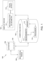
- FIG. 1 is a schematic and block diagram view of an electrophysiological system 100 for mapping electrodes during catheter navigation.
- System 100 includes a computing device 102 configured to communicate with at least one of a display device 104 and/or a catheter 106.
- Computing device 102 includes at least one processor 110 in communication with at least one memory 112.
- Display device 104 is configured to display a digital image.
- display device 104 is configured to display a reconstructed 3D geometry 116 along with a visual effect 118.
- Reconstructed 3D geometry 116 is herein described as geometry 116.
- display device 104 includes any display device suitable for displaying geometry 116 or geometries 116 that are constructed or imported using other known imaging modalities, including but not limited to, computed tomography (CT), intracardiac ultrasound echocardiography (ICE), and/or magnetic resonance imaging (MRI).
- CT computed tomography
- ICE intracardiac ultrasound echocardiography
- MRI magnetic resonance imaging
- display device 104 and computing device 102 are the same device.
- Geometry 116 is an image of a digital reconstruction of the biological tissue 108 used for navigating a catheter 106 within the biological tissue.
- biological tissue 108 is cardiac tissue
- geometry 116 is a digital reconstruction of a human or animal heart muscle.
- Catheter 106 includes at least one electrode 120 for electrical mapping of biological tissue 108.
- catheter 106 is an electrophysiology catheter suitable for electrically mapping a human heart for providing real-time images in vivo of biological tissue regions.
- catheter 106 is an ablation catheter capable of both mapping and therapy.
- catheter 106 may be coupled to a tracking device (not shown) and electrode(s) 120 to generate location signals associated with biological tissue 108.
- Processor 110 registers the detected electrical activity using the location signals from the tracking device and electrode(s) 120.
- Processor 110 then transmits an output signal with the electrical activity signals to display device 104.
- system 100 is the EnSite TM Velocity TM or EnSite Precision TM cardiac mapping and visualization system of Abbott Laboratories.
- Other localization systems may be used in connection with the present teachings, including for example the RHYTHMIA HDX TM mapping system of Boston Scientific Corporation, the CARTO navigation and location system of Biosense Webster, Inc., the AURORA ® system of Northern Digital Inc., Sterotaxis' NIOBE ® Magnetic Navigation System, as well as MediGuide TM Technology from Abbott Laboratories.
- the localization and mapping systems described in the following patents can also be used: United States Patent Nos. 6,990,370; 6,978,168; 6,947,785; 6,939,309; 6,728,562; 6,640,119; 5,983,126; and 5,697,377 .
- Processor 110 is further configured to determine the proximity between at least one electrode 120 and biological tissue 108 using at least one measurement 114.
- measurement 114 includes the shortest distance from the location of at least one electrode 120 to the surface of biological tissue 108.
- Another measurement 114 includes a contact force. The contact force is a positive value when at least one electrode 120 is in contact with a surface of biological tissue 108.
- Another measurement 114 includes an electrode-tissue coupling index value. The electrode-tissue coupling index value is determined from the complex impedance measured when a voltage is applied to at least one electrode 120.
- Yet another measurement 114 includes a Peak to Peak voltage value of an electrogram of at least one electrode 120.
- the at least one measurement may include any other measurement suitable for indicating the proximity between a catheter electrode and a biological tissue.
- visual effect 118 is a digital display effect used to indicate the location of catheter 106, specifically electrode(s) 120, relative to biological tissue 108. At least one measurement 114 is used to determine a proximity between electrode 120 and biological tissue 108, and the determined proximity is translated into a 3D image of catheter 106. Visual effect 118 is placed alongside geometry 116 of the biological tissue to indicate to a user, or a physician, the location of catheter 106 in relation to biological tissue 108.
- Display device 104 displays visual effect 118 alongside geometry 116, based upon at least one measurement 114, showing the proximity between electrodes 120 within catheter 106 and biological tissue 118. This provides a real-time map of catheter 106 and biological tissue 108.
- visual effect 118 is a digital 2D circle effect that highlights various degrees of proximity between electrode(s) 120 and biological tissue 108. Additionally or alternatively, visual effect 118 may be any other visual effect that highlights various degrees of proximity between electrode(s) 120 and biological tissue 108
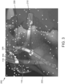
- FIG. 2 and FIG 3 are electrophysiology maps 200 and 300 of system 100.
- Electrophysiology maps 200 and 300 illustrate geometry 116 alongside visual effect 118 and a catheter image 202.
- Catheter image 202 is a digitally reconstructed image representing catheter 106 in relation to biological tissue 108.
- Maps 200 and 300 illustrate several exemplary variations in attributes of visual effects 118 relative to the proximity between electrode(s) 120 and biological tissue 108.
- Display device 104 is configured to display maps 200 and 300.
- visual effect 118 is a digital 2D circle effect that highlights various degrees of proximity between electrode(s) 120 and biological tissue 108. This is what is referred to as the "spotlight" effect.
- the spotlight effect, or spotlight appears on reconstructed 3D geometry 116 of digital display device 104 corresponding to catheter's 106 position relative to biological tissue 108. For example, as the physician moves catheter 106 from a first position ( FIG. 2 ) to a second position ( FIG. 3 ) in relation to a location on biological tissue 108, the spotlight becomes weaker (for example, less bright and more diffused) on corresponding reconstructed 3D geometry 116.
- the proximity threshold value may be user selected or predetermined. In the example embodiment, the default proximity threshold value is four mm, but the user may select a different proximity threshold in a range from one mm to twelve mm. In other embodiments, the proximity threshold is fixed, i.e., not user variable, at four mm. In still other embodiments, the proximity threshold may be varied by the user within any other suitable range of distances.
- visual effect 118 includes attributes that correspond to the actual proximity between catheter electrodes 120 and biological tissue 108. This further provides an even more accurate electrical mapping of catheter 106 and biological tissue 108.
- one attribute includes a change in brightness of visual effect 118 as the proximity of electrode 120 and biological tissue 108 changes.
- Other attributes include, but are not limited to, a change in color intensity of visual effect 118, a decrease of the diffuseness of visual effect 118, and a change in transparency of reconstructed 3D geometry 116 surface relative to the proximity between electrode(s) 120 and biological tissue 108. For example, locations of the displayed reconstructed 3D geometry 116 may become less transparent as the proximity of electrode(s) 120 and biological tissue 108 decrease (i.e., as electrode(s) move closer to biological tissue 108).
- catheter image 202 is within a certain proximity to geometry 116.
- Catheter image 202 includes visual effects 118 in the form of spotlights 204, 206, 208, and 210 (as described above).
- the various sizes and color intensities illustrate different proximities between catheter 106 and biological tissue 108.
- catheter 106 has moved to a second location within biological tissue 108, thus changing the proximity of electrodes 120 to biological tissue 108.
- visual effects 118 on catheter image 202 appear visually distinct from the appearance of visual effects 118 in the first location ( FIG. 2 ).
- spotlights 204, 206, and 210 appear less bright, more diffused, and illustrate a lower intensity of color.
- Spotlight 208 cannot be seen in the second location, indicating that the threshold proximity has been reached.
- the proximity threshold may be defined by the user or physician and programed into processor 110.
- Maps 200 and 300 show that the proximities between electrodes 120 and biological tissue 108 are smaller at the first location ( FIG. 2 ) than at the second location ( FIG. 3 ).
- a physician is able to accurately guide catheter 106 through a blood vessel and into a biological region, such as the chamber of a heart.
- spotlights 204, 206, 208, and 210 are all examples of one embodiment of visual effect 118.
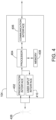
- FIG. 4 illustrates an example configuration of display device 104 used in system 100 shown in FIG. 1 .
- Display device 104 may include, but is not limited to, a computer screen, and/or any device suitable for displaying a reconstructed digital 3D image.
- display device 104 includes a processor 404 for executing instructions.
- executable instructions are stored in a memory area 408.
- Processor 404 may include one or more processing units, for example, a multi-core configuration.
- Memory area 408 is any device allowing information such as executable instructions and/or written works to be stored and retrieved.
- Memory area 408 may include one or more computer readable media.
- Display device 104 also includes at least one media output component 410 for presenting information to user 426.
- Media output component 410 is any component capable of conveying information to user 426.
- media output component 410 includes an output adapter such as a video adapter and/or an audio adapter.
- An output adapter is operatively coupled to processor 404 and operatively couplable to an output device such as a display device, a liquid crystal display (LCD), organic light emitting diode (OLED) display, or "electronic ink” display, or an audio output device, a speaker or headphones.
- LCD liquid crystal display
- OLED organic light emitting diode
- display device 104 includes an input device 402 for receiving input from user 426.
- Input device 402 may include, for example, a keyboard, a pointing device, a mouse, a stylus, a touch sensitive panel, a touch pad, a touch screen, a gyroscope, an accelerometer, a position detector, or an audio input device.
- a single component such as a touch screen may function as both an output device of media output component 410 and input device 402.
- Display device 104 may also include a communication interface 406, which is capable of or configured to be communicatively coupled to a remote device such as the digital account.
- Communication interface 406 may include, for example, a wired or wireless network adapter or a wireless data transceiver for use with a mobile phone network, Global System for Mobile communications (GSM), 3G, or other mobile data network or Worldwide Interoperability for Microwave Access (WIMAX), or an 802.11 wireless network (WLAN).
- GSM Global System for Mobile communications
- 3G 3G
- WIMAX Worldwide Interoperability for Microwave Access
- 802.11 wireless network Wi-Fi
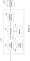
- FIG. 5 illustrates an example configuration of computing device 102 used in the system as shown in FIG. 1 .
- Computing device 102 includes a processor 110 for executing instructions. Instructions may be stored in a memory area 112, for example.
- Processor 110 may include one or more processing units (e.g., in a multi-core configuration) for executing instructions. The instructions may be executed within a variety of different operating systems on the computing device 102, such as UNIX, LINUX, Microsoft Windows ® , etc. It should also be appreciated that upon initiation of a computer-based method, various instructions may be executed during initialization. Some operations may be required in order to perform one or more processes described herein, while other operations may be more general and/or specific to a particular programming language (e.g., C, C#, C++, Java, or other suitable programming languages, etc.).
- a particular programming language e.g., C, C#, C++, Java, or other suitable programming languages, etc.
- Processor 110 is operatively coupled to a communication interface 515 such that computing device 102 is capable of communicating with a remote device such as a user system, a catheter 106, a display device 104, or another computing device 102.
- Communication interface 515 may include, for example, a wired or wireless network adapter or a wireless data transceiver for use with a mobile phone network, Global System for Mobile communications (GSM), 3G, or other mobile data network or Worldwide Interoperability for Microwave Access (WIMAX).
- GSM Global System for Mobile communications
- 3G Global System for Mobile communications
- WIMAX Worldwide Interoperability for Microwave Access
- Storage device 520 is any computer-operated hardware suitable for storing and/or retrieving data.
- storage device 520 is integrated in computing device 102.
- computing device 102 may include one or more hard disk drives as storage device 520.
- storage device 520 is external to computing device 102 and may be accessed by a plurality of computing devices 102.
- storage device 520 may include multiple storage units such as hard disks or solid state disks in a redundant array of inexpensive disks (RAID) configuration.
- Storage device 520 may include a storage area network (SAN) and/or a network attached storage (NAS) system.
- SAN storage area network
- NAS network attached storage
- processor 110 is operatively coupled to storage device 520 via a storage interface 525.
- Storage interface 525 is any component capable of providing processor 110 with access to storage device 520.
- Storage interface 525 may include, for example, an Advanced Technology Attachment (ATA) adapter, a Serial ATA (SATA) adapter, a Small Computer System Interface (SCSI) adapter, a RAID controller, a SAN adapter, a network adapter, and/or any component providing processor 110 with access to storage device 520.
- ATA Advanced Technology Attachment
- SATA Serial ATA
- SCSI Small Computer System Interface
- Computing device 102 may also include at least one media output component 530 for presenting information, e.g., images, to user 426.
- Media output component 530 is any component capable of conveying information to user 426.
- media output component 530 includes an output adapter such as a video adapter and/or an audio adapter.
- An output adapter is operatively coupled to processor 110 and operatively couplable to an output device such as a display device, a liquid crystal display (LCD), organic light emitting diode (OLED) display, or "electronic ink” display, or an audio output device, a speaker or headphones.
- LCD liquid crystal display
- OLED organic light emitting diode
- Memory 112 may include, but is not limited to, random access memory (RAM) such as dynamic RAM (DRAM) or static RAM (SRAM), read-only memory (ROM), erasable programmable read-only memory (EPROM), electrically erasable programmable read-only memory (EEPROM), and non-volatile RAM (NVRAM).
- RAM random access memory
- DRAM dynamic RAM
- SRAM static RAM
- ROM read-only memory
- EPROM erasable programmable read-only memory
- EEPROM electrically erasable programmable read-only memory
- NVRAM non-volatile RAM
- Stored in memory area 112 are, for example, computer readable instructions for providing a user interface to user 426 via media output component 530 and, optionally, receiving and processing input from input device 540, sensor interface 550, display device 104, and/or catheter 106.
- a user interface may include, among other possibilities, an image viewer and client application. Image viewers enable users, such as user 426, to display and interact with media and other information received from display device 104, and/or catheter 106.
- a client application allows user 426 to interact with display device 104, and/or catheter 106, e.g., requesting a frame to be captured.
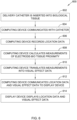
- FIG. 6 is a flow diagram of a method 600 for using catheter navigation and mapping systems.
- FIG. 6 may represent, for example, an exemplary method for displaying electrodes and visual effects on an electrophysiology map during catheter navigation using the exemplary system described herein with respect to FIG. 1 .
- a catheter including a mounted tracking device and at least one electrode, is inserted 602 into the patient's heart at a location proximate a biological tissue for electrophysiological mapping.
- a computing device then communicates 604 with the catheter, either through a wired or wireless connection, and records 606 electrical location data retrieved from the catheter.
- the computing device uses the recordings to calculate 608 measurements indicating the proximity of the electrodes within the catheter to the biological tissue.
- the computing device translates 610 the measurements into visual effect data.
- the computing device communicates 612 the electrical location data and the visual effect data to a display device.
- the display device displays 614 the location data and the visual effect data to the user on a display screen.
- joinder references do not necessarily infer that two elements are directly connected and in fixed relation to each other. It is intended that all matter contained in the above description or shown in the accompanying drawings shall be interpreted as illustrative only and not limiting. Changes in detail or structure may be made without departing from the spirit of the disclosure as defined in the appended claims.
Landscapes
- Health & Medical Sciences (AREA)
- Life Sciences & Earth Sciences (AREA)
- Engineering & Computer Science (AREA)
- Public Health (AREA)
- General Health & Medical Sciences (AREA)
- Medical Informatics (AREA)
- Animal Behavior & Ethology (AREA)
- Physics & Mathematics (AREA)
- Biophysics (AREA)
- Pathology (AREA)
- Biomedical Technology (AREA)
- Heart & Thoracic Surgery (AREA)
- Veterinary Medicine (AREA)
- Molecular Biology (AREA)
- Surgery (AREA)
- Radiology & Medical Imaging (AREA)
- Nuclear Medicine, Radiotherapy & Molecular Imaging (AREA)
- Gynecology & Obstetrics (AREA)
- Human Computer Interaction (AREA)
- Cardiology (AREA)
- Epidemiology (AREA)
- Primary Health Care (AREA)
- Measurement And Recording Of Electrical Phenomena And Electrical Characteristics Of The Living Body (AREA)
Claims (12)
- Elektrophysiologiesystem zur Erleichterung einer Visualisierung einer Nähe einer Vielzahl von Katheterelektroden (120) zu einer 3D-Geometrie eines biologischen Gewebes (108), wobei das System umfasst:die Vielzahl von Katheterelektroden (120);eine Rechenvorrichtung (102), die dazu konfiguriert ist, Aufzeichnungen, die von der Vielzahl von Katheterelektroden (120) empfangen werden, zu empfangen, zur Berechnung von Messwerten, die die Nähe der Vielzahl von Katheterelektroden (120) zu dem biologischen Gewebe angeben, und umfassend:mindestens einen Prozessor (110) in Kommunikation mit einem Speicher, wobei der Prozessor dazu konfiguriert ist, die Nähe zwischen der Vielzahl von Katheterelektroden (120) und dem biologischen Gewebe (108) unter Verwendung mindestens eines Messwerts (114) zu bestimmen, undeine Echtzeit-Elektrophysiologiekarte (200) zu erzeugen, die eine 3D-Geometrie (116) des biologischen Gewebes (108) neben einem visuellen Effekt (118) und einem Katheterbild (202) darstellt, wobei der visuelle Effekt (118) ein digitaler Punktstrahler mit einer 2D-Form ist, der auf eine Oberfläche der 3D-Geometrie projiziert wird, wobei der digitale Punktstrahler die Nähe zwischen der Vielzahl von Katheterelektroden (120) und dem biologischen Gewebe (108) angibt und der digitale Punktstrahler verschiedene Grade der Nähe zwischen der Vielzahl von Katheterelektroden (120) und dem biologischen Gewebe (108) hervorhebt, wobei kein visueller Effekt für eine bestimmte Elektrode der Vielzahl von Katheterelektroden (120) produziert wird, wenn ein Abstand zwischen der bestimmten Elektrode und dem biologischen Gewebe (108) einen vorbestimmten Näheschwellenwert überschreitet; undeine Anzeigevorrichtung (104), konfiguriert zum:
Anzeigen der Echtzeit-Elektrophysiologiekarte (200). - System nach Anspruch 1, wobei die Rechenvorrichtung dazu konfiguriert ist, die kürzesten Abstände von Stellen der Vielzahl von Elektroden (120) zu einer Geometrieoberfläche des biologischen Gewebes (108) als Messwerte zu berechnen, und/oderwobei die Rechenvorrichtung dazu konfiguriert ist, Kontaktkräfte als Messwerte zu berechnen, wobei die Kontaktkraft einer bestimmten Elektrode der Vielzahl von Elektroden ein positiver Wert ist, wenn die bestimmte Elektrode (120) mit einer biologischen Oberfläche in Kontakt steht, und/oderwobei die Rechenvorrichtung dazu konfiguriert ist, einen Elektrode-Gewebe-Kopplungsindex als Messwerte zu berechnen, und wobei der Elektrode-Gewebe-Kopplungsindex einer bestimmten Elektrode der Vielzahl von Elektroden aus einer gemessenen komplexen Impedanz bestimmt wird, wenn eine Spannung an die bestimmte Elektrode angelegt wird, und/oderwobei die Rechenvorrichtung dazu konfiguriert ist, eine Spitze-Spitze-Spannung eines Elektrogramms an einer bestimmten Elektrode der Vielzahl von Elektroden als Messwert zu berechnen.
- System nach Anspruch 1, wobei der digitale Punktstrahler an einer Position auf der 3D-Geometrie zentriert ist, die einen kürzesten Abstand zwischen der assoziierten Elektrode und der Oberfläche der 3D-Geometrie aufweist.
- System nach Anspruch 3, wobei der digitale Punktstrahler eine Farbe aufweist und wobei die Intensität und die Helligkeit der Farbe einer bestimmten Elektrode der Vielzahl von Elektroden zunehmen, wenn die Nähe zwischen der bestimmten Elektrode (120) und der 3D-Geometrie abnimmt, oder
wobei eine Diffusität des digitalen Punktstrahlers einer bestimmten Elektrode der Vielzahl von Elektroden abnimmt, wenn die Nähe zwischen der bestimmten Elektrode (120) und der 3D-Geometrie abnimmt. - System nach Anspruch 3, wobei eine Transparenz der 3D-Geometrieoberfläche einer bestimmten Elektrode der Vielzahl von Elektroden abnimmt, wenn die Nähe zwischen der bestimmten Elektrode (120) und der 3D-Geometrie abnimmt.
- System nach Anspruch 5, wobei der digitale Punktstrahler einer bestimmten Elektrode der Vielzahl von Elektroden verschwindet, wenn eine Grenznähe zwischen der bestimmten Elektrode und der 3D-Geometrie überschritten wird.
- Verfahren zur Erleichterung einer Visualisierung einer Nähe einer Vielzahl von elektroden (120) zu einer 3D-Geometrie eines biologischen Gewebes während einer 3D-Elektrophysiologie, wobei das Verfahren umfasst:Berechnen von Messwerten, die die Nähe der Vielzahl von elektroden (120) zu dem biologischen Gewebe angeben, auf der Basis von Aufzeichnungen, die von der Vielzahl von Katheterelektroden (120) empfangen werden;Bestimmen einer Nähe zwischen der Vielzahl von Elektroden (120) und dem biologischen Gewebe (108) unter Verwendung mindestens eines Messwerts unter Verwendung eines Computers, beinhaltend einen Prozessor in Kommunikation mit einem Speicher;Erzeugen einer Echtzeit-Elektrophysiologiekarte (200), die eine 3D-Geometrie (116) des biologischen Gewebes (108) neben einem visuellen Effekt (118) und einem Katheterbild (202) darstellt, wobei der visuelle Effekt (118) ein digitaler Punktstrahler mit einer 2D-Form ist, der auf eine Oberfläche der 3D-Geometrie projiziert wird, wobei der digitale Punktstrahler die Nähe zwischen der Vielzahl von Katheterelektroden (120) und dem biologischen Gewebe (108) angibt und der digitale Punktstrahler verschiedene Grade der Nähe zwischen der Vielzahl von Katheterelektroden (120) und dem biologischen Gewebe (108) hervorhebt, wobei kein visueller Effekt für eine bestimmte Elektrode der Vielzahl von Katheterelektroden (120) produziert wird, wenn ein Abstand zwischen der bestimmten Elektrode und dem biologischen Gewebe (108) einen vorbestimmten Näheschwellenwert überschreitet; undAnzeigen der Echtzeit-Elektrophysiologiekarte (200) auf einer Anzeigevorrichtung (104).
- Verfahren nach Anspruch 7, wobei das Berechnen der Messwerte ein Berechnen der kürzesten Abstände von Stellen der Vielzahl von Elektroden (120) zu einer Geometrieoberfläche des biologischen Gewebes (108) beinhaltet.
- Verfahren nach Anspruch 7, wobei das Berechnen der Messwerte ein Berechnen einer Kontaktkraft für eine bestimmte Elektrode der Vielzahl von Elektroden beinhaltet, wobei die Kontaktkraft ein positiver Wert ist, wenn die bestimmte Elektrode mit einer biologischen Oberfläche in Kontakt steht, und/oderwobei das Berechnen der Messwerte ein Berechnen eines Elektrode-Gewebe-Kopplungsindexes für eine bestimmte Elektrode der Vielzahl von Elektroden beinhaltet und wobei der Elektrode-Gewebe-Kopplungsindex aus einer gemessenen komplexen Impedanz bestimmt wird, wenn eine Spannung an die bestimmte Elektrode angelegt wird, und/oderwobei das Berechnen von Messwerten ein Berechnen einer Spitze-Spitze-Spannung eines Elektrogramms an einer bestimmten Elektrode beinhaltet.
- Verfahren nach Anspruch 9, wobei der digitale Punktstrahler einer bestimmten Elektrode der Vielzahl von Elektroden an einer Position auf der 3D-Geometrie zentriert ist, die einen kürzesten Abstand zwischen der assoziierten Elektrode und der Oberfläche der 3D-Geometrie aufweist.
- Verfahren nach Anspruch 10, wobei der digitale Punktstrahler eine Farbe aufweist und wobei die Intensität und die Helligkeit der Farbe einer bestimmten Elektrode der Vielzahl von Elektroden zunehmen, wenn die Nähe zwischen der bestimmten Elektrode und der 3D-Geometrie abnimmt.
- Verfahren nach Anspruch 11, wobei eine Diffusität des digitalen Punktstrahlers einer bestimmten Elektrode der Vielzahl von Elektroden abnimmt, wenn die Nähe zwischen der bestimmten Elektrode und der 3D-Geometrie abnimmt.
Applications Claiming Priority (2)
| Application Number | Priority Date | Filing Date | Title |
|---|---|---|---|
| US201762553189P | 2017-09-01 | 2017-09-01 | |
| PCT/US2018/048268 WO2019046250A1 (en) | 2017-09-01 | 2018-08-28 | SYSTEM AND METHOD FOR VISUALIZING A PROXIMITY OF A CATHETER ELECTRODE TO A 3D GEOMETRY OF A BIOLOGICAL TISSUE |
Publications (2)
| Publication Number | Publication Date |
|---|---|
| EP3675729A1 EP3675729A1 (de) | 2020-07-08 |
| EP3675729B1 true EP3675729B1 (de) | 2024-11-20 |
Family
ID=63686082
Family Applications (1)
| Application Number | Title | Priority Date | Filing Date |
|---|---|---|---|
| EP18779098.5A Active EP3675729B1 (de) | 2017-09-01 | 2018-08-28 | System und verfahren zur visualisierung einer nähe einer katheterelektrode zu einer 3d-geometrie von biologischem gewebe |
Country Status (3)
| Country | Link |
|---|---|
| US (2) | US12396684B2 (de) |
| EP (1) | EP3675729B1 (de) |
| WO (1) | WO2019046250A1 (de) |
Families Citing this family (3)
| Publication number | Priority date | Publication date | Assignee | Title |
|---|---|---|---|---|
| US12161506B2 (en) | 2022-09-01 | 2024-12-10 | Biosense Webster (Israel) Ltd. | Safety alert based on 4D intracardiac echo (ICE) catheter tracking |
| EP4678092A1 (de) * | 2024-07-11 | 2026-01-14 | Biosense Webster (Israel) Ltd. | Verfahren, systeme und gui für verbesserte visuelle echtzeit-rückkopplung einer intraluminalen kathetereinrastung |
| IL314268B2 (en) * | 2024-07-11 | 2025-10-01 | Biosense Webster Israel Ltd | Systems, methods, and graphical interface for improved visual resolution of catheter-tissue interfacing |
Citations (8)
| Publication number | Priority date | Publication date | Assignee | Title |
|---|---|---|---|---|
| US20050228251A1 (en) | 2004-03-30 | 2005-10-13 | General Electric Company | System and method for displaying a three-dimensional image of an organ or structure inside the body |
| WO2006060613A1 (en) | 2004-12-01 | 2006-06-08 | Boston Scientific Scimed, Inc. | System and use thereof to provide indication of proximity between catheter and location of interest |
| US20090163904A1 (en) | 2005-12-06 | 2009-06-25 | St. Jude Medical, Atrial Fibrillation Division, Inc. | System and Method for Assessing Coupling Between an Electrode and Tissue |
| US20090275827A1 (en) | 2005-12-06 | 2009-11-05 | Aiken Robert D | System and method for assessing the proximity of an electrode to tissue in a body |
| US20140018665A1 (en) | 2012-07-12 | 2014-01-16 | Siemens Corporation | Compressable catheter tip with image-based force sensing |
| US20160128770A1 (en) | 2009-05-13 | 2016-05-12 | St. Jude Medical, Atrial Fibrillation Division, Inc. | System and method for presenting information representative of lesion formation in tissue during an ablation procedure |
| US20160242667A1 (en) | 2015-02-20 | 2016-08-25 | Boston Scientific Scimed Inc. | Tissue contact sensing using a medical device |
| WO2018130981A1 (en) | 2017-01-12 | 2018-07-19 | Navix International Limited | Flattened view for intra-lumenal navigation |
Family Cites Families (10)
| Publication number | Priority date | Publication date | Assignee | Title |
|---|---|---|---|---|
| DE69315354T2 (de) | 1992-09-23 | 1998-03-19 | Endocardial Solutions Inc | Endokard-mapping system |
| US5662108A (en) | 1992-09-23 | 1997-09-02 | Endocardial Solutions, Inc. | Electrophysiology mapping system |
| US6947785B1 (en) | 1993-09-23 | 2005-09-20 | Endocardial Solutions, Inc. | Interface system for endocardial mapping catheter |
| US5697377A (en) | 1995-11-22 | 1997-12-16 | Medtronic, Inc. | Catheter mapping system and method |
| US8406866B2 (en) | 2005-12-06 | 2013-03-26 | St. Jude Medical, Atrial Fibrillation Division, Inc. | System and method for assessing coupling between an electrode and tissue |
| US8478388B2 (en) * | 2009-04-07 | 2013-07-02 | Pacesetter, Inc. | Cardiac coordinate system for motion analysis |
| US9393068B1 (en) | 2009-05-08 | 2016-07-19 | St. Jude Medical International Holding S.À R.L. | Method for predicting the probability of steam pop in RF ablation therapy |
| US20110160569A1 (en) * | 2009-12-31 | 2011-06-30 | Amit Cohen | system and method for real-time surface and volume mapping of anatomical structures |
| US10342633B2 (en) * | 2016-06-20 | 2019-07-09 | Toshiba Medical Systems Corporation | Medical image data processing system and method |
| US20180360342A1 (en) * | 2017-06-16 | 2018-12-20 | Biosense Webster (Israel) Ltd. | Renal ablation and visualization system and method with composite anatomical display image |
-
2018
- 2018-08-28 EP EP18779098.5A patent/EP3675729B1/de active Active
- 2018-08-28 WO PCT/US2018/048268 patent/WO2019046250A1/en not_active Ceased
- 2018-08-28 US US16/640,394 patent/US12396684B2/en active Active
-
2025
- 2025-07-24 US US19/279,267 patent/US20250345001A1/en active Pending
Patent Citations (8)
| Publication number | Priority date | Publication date | Assignee | Title |
|---|---|---|---|---|
| US20050228251A1 (en) | 2004-03-30 | 2005-10-13 | General Electric Company | System and method for displaying a three-dimensional image of an organ or structure inside the body |
| WO2006060613A1 (en) | 2004-12-01 | 2006-06-08 | Boston Scientific Scimed, Inc. | System and use thereof to provide indication of proximity between catheter and location of interest |
| US20090163904A1 (en) | 2005-12-06 | 2009-06-25 | St. Jude Medical, Atrial Fibrillation Division, Inc. | System and Method for Assessing Coupling Between an Electrode and Tissue |
| US20090275827A1 (en) | 2005-12-06 | 2009-11-05 | Aiken Robert D | System and method for assessing the proximity of an electrode to tissue in a body |
| US20160128770A1 (en) | 2009-05-13 | 2016-05-12 | St. Jude Medical, Atrial Fibrillation Division, Inc. | System and method for presenting information representative of lesion formation in tissue during an ablation procedure |
| US20140018665A1 (en) | 2012-07-12 | 2014-01-16 | Siemens Corporation | Compressable catheter tip with image-based force sensing |
| US20160242667A1 (en) | 2015-02-20 | 2016-08-25 | Boston Scientific Scimed Inc. | Tissue contact sensing using a medical device |
| WO2018130981A1 (en) | 2017-01-12 | 2018-07-19 | Navix International Limited | Flattened view for intra-lumenal navigation |
Non-Patent Citations (4)
| Title |
|---|
| ANONYMOUS: "CARTO3 SYSTEM - Instructions for Use - Software Version 4.3", BIOSENSE WEBSTER, 1 November 2015 (2015-11-01), XP093308248 |
| BUBIEN ROSEMARY, OSORIO JOSE, RAJENDRA ANIL, ARCINIEGAS JOAQUIN: "Continuous Multi-Electrode Mapping: Single-Center Experience", EP LAB DIGEST, 1 January 2016 (2016-01-01), XP093308243, Retrieved from the Internet <URL:https://www.hmpgloballearningnetwork.com/site/eplab/articles/continuous-multi-electrode-mapping-single-center-experience> |
| DENSFORD FINK: "Biosense Webster launches cardiac mapping system", BIOSENSE WEBSTER, 22 June 2015 (2015-06-22), XP093308242, Retrieved from the Internet <URL:https://www.massdevice.com/biosense-webster-launches-cardiac-mapping-system/> |
| JOHNSON & JOHNSON MEDTECH | ELECTROPHYSIOLOGY: "Case Study: Ripple Mapping Dr. Brenyo", 18 August 2017 (2017-08-18), XP093308251, Retrieved from the Internet <URL:https://www.youtube.com/watch?v=roLSY96nI_o> |
Also Published As
| Publication number | Publication date |
|---|---|
| US12396684B2 (en) | 2025-08-26 |
| US20250345001A1 (en) | 2025-11-13 |
| US20200359968A1 (en) | 2020-11-19 |
| WO2019046250A1 (en) | 2019-03-07 |
| EP3675729A1 (de) | 2020-07-08 |
Similar Documents
| Publication | Publication Date | Title |
|---|---|---|
| EP3797691B1 (de) | 3d-darstellung der intrakardialen aktivität | |
| US20250345001A1 (en) | System and method for visualizing a proximity of a catheter electrode to a 3d geometry of biological tissue | |
| CN108882854B (zh) | 3d医学图像的虚拟现实或增强现实可视化 | |
| JP6719885B2 (ja) | 心内信号を利用した位置合わせマップ | |
| EP3206576B1 (de) | Verfahren und systeme zum mapping der lokalen erregungsleitungsgeschwindigkeit | |
| US6711429B1 (en) | System and method for determining the location of a catheter during an intra-body medical procedure | |
| EP2085026B1 (de) | System zur Bestimmung des Ortes eines Katheters während eines intrakorporalen medizinischen Verfahrens | |
| US20030074011A1 (en) | System and method of recording and displaying in context of an image a location of at least one point-of-interest in a body during an intra-body medical procedure | |
| US20040006268A1 (en) | System and method of recording and displaying in context of an image a location of at least one point-of-interest in a body during an intra-body medical procedure | |
| JP7460355B2 (ja) | 医療ユーザインターフェース | |
| JP2018514279A (ja) | リアルタイム電気生理学的マッピングのためのシステムおよび方法 | |
| CA2967000A1 (en) | System for tracking and imaging a treatment probe | |
| US20050228251A1 (en) | System and method for displaying a three-dimensional image of an organ or structure inside the body | |
| EP4233762B1 (de) | System zur verfolgung und visualisierung von medizinischen vorrichtungen | |
| US20250032035A1 (en) | Methods and systems for shaving an anatomical map | |
| HK40079359A (en) | Virtual reality or augmented reality visualization of 3d medical images | |
| WO2020106664A1 (en) | System and method for volumetric display of anatomy with periodic motion | |
| HK1263061A1 (en) | Virtual reality or augmented reality visualization of 3d medical images | |
| HK1263061B (en) | Virtual reality or augmented reality visualization of 3d medical images |
Legal Events
| Date | Code | Title | Description |
|---|---|---|---|
| STAA | Information on the status of an ep patent application or granted ep patent |
Free format text: STATUS: UNKNOWN |
|
| STAA | Information on the status of an ep patent application or granted ep patent |
Free format text: STATUS: THE INTERNATIONAL PUBLICATION HAS BEEN MADE |
|
| PUAI | Public reference made under article 153(3) epc to a published international application that has entered the european phase |
Free format text: ORIGINAL CODE: 0009012 |
|
| STAA | Information on the status of an ep patent application or granted ep patent |
Free format text: STATUS: REQUEST FOR EXAMINATION WAS MADE |
|
| 17P | Request for examination filed |
Effective date: 20200217 |
|
| AK | Designated contracting states |
Kind code of ref document: A1 Designated state(s): AL AT BE BG CH CY CZ DE DK EE ES FI FR GB GR HR HU IE IS IT LI LT LU LV MC MK MT NL NO PL PT RO RS SE SI SK SM TR |
|
| AX | Request for extension of the european patent |
Extension state: BA ME |
|
| DAV | Request for validation of the european patent (deleted) | ||
| DAX | Request for extension of the european patent (deleted) | ||
| STAA | Information on the status of an ep patent application or granted ep patent |
Free format text: STATUS: EXAMINATION IS IN PROGRESS |
|
| 17Q | First examination report despatched |
Effective date: 20220517 |
|
| P01 | Opt-out of the competence of the unified patent court (upc) registered |
Effective date: 20230616 |
|
| GRAP | Despatch of communication of intention to grant a patent |
Free format text: ORIGINAL CODE: EPIDOSNIGR1 |
|
| STAA | Information on the status of an ep patent application or granted ep patent |
Free format text: STATUS: GRANT OF PATENT IS INTENDED |
|
| INTG | Intention to grant announced |
Effective date: 20240613 |
|
| GRAS | Grant fee paid |
Free format text: ORIGINAL CODE: EPIDOSNIGR3 |
|
| GRAA | (expected) grant |
Free format text: ORIGINAL CODE: 0009210 |
|
| STAA | Information on the status of an ep patent application or granted ep patent |
Free format text: STATUS: THE PATENT HAS BEEN GRANTED |
|
| AK | Designated contracting states |
Kind code of ref document: B1 Designated state(s): AL AT BE BG CH CY CZ DE DK EE ES FI FR GB GR HR HU IE IS IT LI LT LU LV MC MK MT NL NO PL PT RO RS SE SI SK SM TR |
|
| REG | Reference to a national code |
Ref country code: GB Ref legal event code: FG4D |
|
| REG | Reference to a national code |
Ref country code: CH Ref legal event code: EP |
|
| REG | Reference to a national code |
Ref country code: DE Ref legal event code: R096 Ref document number: 602018076747 Country of ref document: DE |
|
| REG | Reference to a national code |
Ref country code: IE Ref legal event code: FG4D |
|
| REG | Reference to a national code |
Ref country code: LT Ref legal event code: MG9D |
|
| REG | Reference to a national code |
Ref country code: NL Ref legal event code: MP Effective date: 20241120 |
|
| PG25 | Lapsed in a contracting state [announced via postgrant information from national office to epo] |
Ref country code: IS Free format text: LAPSE BECAUSE OF FAILURE TO SUBMIT A TRANSLATION OF THE DESCRIPTION OR TO PAY THE FEE WITHIN THE PRESCRIBED TIME-LIMIT Effective date: 20250320 Ref country code: PT Free format text: LAPSE BECAUSE OF FAILURE TO SUBMIT A TRANSLATION OF THE DESCRIPTION OR TO PAY THE FEE WITHIN THE PRESCRIBED TIME-LIMIT Effective date: 20250320 Ref country code: HR Free format text: LAPSE BECAUSE OF FAILURE TO SUBMIT A TRANSLATION OF THE DESCRIPTION OR TO PAY THE FEE WITHIN THE PRESCRIBED TIME-LIMIT Effective date: 20241120 |
|
| PG25 | Lapsed in a contracting state [announced via postgrant information from national office to epo] |
Ref country code: FI Free format text: LAPSE BECAUSE OF FAILURE TO SUBMIT A TRANSLATION OF THE DESCRIPTION OR TO PAY THE FEE WITHIN THE PRESCRIBED TIME-LIMIT Effective date: 20241120 Ref country code: NL Free format text: LAPSE BECAUSE OF FAILURE TO SUBMIT A TRANSLATION OF THE DESCRIPTION OR TO PAY THE FEE WITHIN THE PRESCRIBED TIME-LIMIT Effective date: 20241120 |
|
| REG | Reference to a national code |
Ref country code: AT Ref legal event code: MK05 Ref document number: 1742799 Country of ref document: AT Kind code of ref document: T Effective date: 20241120 |
|
| PG25 | Lapsed in a contracting state [announced via postgrant information from national office to epo] |
Ref country code: BG Free format text: LAPSE BECAUSE OF FAILURE TO SUBMIT A TRANSLATION OF THE DESCRIPTION OR TO PAY THE FEE WITHIN THE PRESCRIBED TIME-LIMIT Effective date: 20241120 |
|
| PG25 | Lapsed in a contracting state [announced via postgrant information from national office to epo] |
Ref country code: ES Free format text: LAPSE BECAUSE OF FAILURE TO SUBMIT A TRANSLATION OF THE DESCRIPTION OR TO PAY THE FEE WITHIN THE PRESCRIBED TIME-LIMIT Effective date: 20241120 |
|
| PG25 | Lapsed in a contracting state [announced via postgrant information from national office to epo] |
Ref country code: NO Free format text: LAPSE BECAUSE OF FAILURE TO SUBMIT A TRANSLATION OF THE DESCRIPTION OR TO PAY THE FEE WITHIN THE PRESCRIBED TIME-LIMIT Effective date: 20250220 |
|
| PG25 | Lapsed in a contracting state [announced via postgrant information from national office to epo] |
Ref country code: LV Free format text: LAPSE BECAUSE OF FAILURE TO SUBMIT A TRANSLATION OF THE DESCRIPTION OR TO PAY THE FEE WITHIN THE PRESCRIBED TIME-LIMIT Effective date: 20241120 Ref country code: AT Free format text: LAPSE BECAUSE OF FAILURE TO SUBMIT A TRANSLATION OF THE DESCRIPTION OR TO PAY THE FEE WITHIN THE PRESCRIBED TIME-LIMIT Effective date: 20241120 Ref country code: GR Free format text: LAPSE BECAUSE OF FAILURE TO SUBMIT A TRANSLATION OF THE DESCRIPTION OR TO PAY THE FEE WITHIN THE PRESCRIBED TIME-LIMIT Effective date: 20250221 |
|
| PG25 | Lapsed in a contracting state [announced via postgrant information from national office to epo] |
Ref country code: PL Free format text: LAPSE BECAUSE OF FAILURE TO SUBMIT A TRANSLATION OF THE DESCRIPTION OR TO PAY THE FEE WITHIN THE PRESCRIBED TIME-LIMIT Effective date: 20241120 |
|
| PG25 | Lapsed in a contracting state [announced via postgrant information from national office to epo] |
Ref country code: RS Free format text: LAPSE BECAUSE OF FAILURE TO SUBMIT A TRANSLATION OF THE DESCRIPTION OR TO PAY THE FEE WITHIN THE PRESCRIBED TIME-LIMIT Effective date: 20250220 |
|
| PG25 | Lapsed in a contracting state [announced via postgrant information from national office to epo] |
Ref country code: SM Free format text: LAPSE BECAUSE OF FAILURE TO SUBMIT A TRANSLATION OF THE DESCRIPTION OR TO PAY THE FEE WITHIN THE PRESCRIBED TIME-LIMIT Effective date: 20241120 |
|
| PG25 | Lapsed in a contracting state [announced via postgrant information from national office to epo] |
Ref country code: DK Free format text: LAPSE BECAUSE OF FAILURE TO SUBMIT A TRANSLATION OF THE DESCRIPTION OR TO PAY THE FEE WITHIN THE PRESCRIBED TIME-LIMIT Effective date: 20241120 |
|
| PG25 | Lapsed in a contracting state [announced via postgrant information from national office to epo] |
Ref country code: EE Free format text: LAPSE BECAUSE OF FAILURE TO SUBMIT A TRANSLATION OF THE DESCRIPTION OR TO PAY THE FEE WITHIN THE PRESCRIBED TIME-LIMIT Effective date: 20241120 |
|
| PG25 | Lapsed in a contracting state [announced via postgrant information from national office to epo] |
Ref country code: RO Free format text: LAPSE BECAUSE OF FAILURE TO SUBMIT A TRANSLATION OF THE DESCRIPTION OR TO PAY THE FEE WITHIN THE PRESCRIBED TIME-LIMIT Effective date: 20241120 |
|
| PG25 | Lapsed in a contracting state [announced via postgrant information from national office to epo] |
Ref country code: SK Free format text: LAPSE BECAUSE OF FAILURE TO SUBMIT A TRANSLATION OF THE DESCRIPTION OR TO PAY THE FEE WITHIN THE PRESCRIBED TIME-LIMIT Effective date: 20241120 |
|
| PG25 | Lapsed in a contracting state [announced via postgrant information from national office to epo] |
Ref country code: CZ Free format text: LAPSE BECAUSE OF FAILURE TO SUBMIT A TRANSLATION OF THE DESCRIPTION OR TO PAY THE FEE WITHIN THE PRESCRIBED TIME-LIMIT Effective date: 20241120 |
|
| REG | Reference to a national code |
Ref country code: DE Ref legal event code: R026 Ref document number: 602018076747 Country of ref document: DE |
|
| PLBI | Opposition filed |
Free format text: ORIGINAL CODE: 0009260 |
|
| PLAX | Notice of opposition and request to file observation + time limit sent |
Free format text: ORIGINAL CODE: EPIDOSNOBS2 |
|
| PG25 | Lapsed in a contracting state [announced via postgrant information from national office to epo] |
Ref country code: SE Free format text: LAPSE BECAUSE OF FAILURE TO SUBMIT A TRANSLATION OF THE DESCRIPTION OR TO PAY THE FEE WITHIN THE PRESCRIBED TIME-LIMIT Effective date: 20241120 |
|
| 26 | Opposition filed |
Opponent name: MEDTRONIC INC. Effective date: 20250819 |
|
| PGFP | Annual fee paid to national office [announced via postgrant information from national office to epo] |
Ref country code: DE Payment date: 20250709 Year of fee payment: 8 |
|
| PGFP | Annual fee paid to national office [announced via postgrant information from national office to epo] |
Ref country code: IT Payment date: 20250811 Year of fee payment: 8 |
|
| PGFP | Annual fee paid to national office [announced via postgrant information from national office to epo] |
Ref country code: GB Payment date: 20250710 Year of fee payment: 8 |
|
| PGFP | Annual fee paid to national office [announced via postgrant information from national office to epo] |
Ref country code: FR Payment date: 20250709 Year of fee payment: 8 |
|
| PLBB | Reply of patent proprietor to notice(s) of opposition received |
Free format text: ORIGINAL CODE: EPIDOSNOBS3 |