EP3675609B1 - Electronic control component bracket - Google Patents
Electronic control component bracket Download PDFInfo
- Publication number
- EP3675609B1 EP3675609B1 EP19210628.4A EP19210628A EP3675609B1 EP 3675609 B1 EP3675609 B1 EP 3675609B1 EP 19210628 A EP19210628 A EP 19210628A EP 3675609 B1 EP3675609 B1 EP 3675609B1
- Authority
- EP
- European Patent Office
- Prior art keywords
- electronic control
- control component
- elastic pieces
- elastic
- bracket
- Prior art date
- Legal status (The legal status is an assumption and is not a legal conclusion. Google has not performed a legal analysis and makes no representation as to the accuracy of the status listed.)
- Active
Links
Images





Classifications
-
- H—ELECTRICITY
- H05—ELECTRIC TECHNIQUES NOT OTHERWISE PROVIDED FOR
- H05K—PRINTED CIRCUITS; CASINGS OR CONSTRUCTIONAL DETAILS OF ELECTRIC APPARATUS; MANUFACTURE OF ASSEMBLAGES OF ELECTRICAL COMPONENTS
- H05K5/00—Casings, cabinets or drawers for electric apparatus
- H05K5/0026—Casings, cabinets or drawers for electric apparatus provided with connectors and printed circuit boards [PCB], e.g. automotive electronic control units
- H05K5/0073—Casings, cabinets or drawers for electric apparatus provided with connectors and printed circuit boards [PCB], e.g. automotive electronic control units having specific features for mounting the housing on an external structure
-
- B—PERFORMING OPERATIONS; TRANSPORTING
- B60—VEHICLES IN GENERAL
- B60R—VEHICLES, VEHICLE FITTINGS, OR VEHICLE PARTS, NOT OTHERWISE PROVIDED FOR
- B60R16/00—Electric or fluid circuits specially adapted for vehicles and not otherwise provided for; Arrangement of elements of electric or fluid circuits specially adapted for vehicles and not otherwise provided for
- B60R16/02—Electric or fluid circuits specially adapted for vehicles and not otherwise provided for; Arrangement of elements of electric or fluid circuits specially adapted for vehicles and not otherwise provided for electric constitutive elements
- B60R16/023—Electric or fluid circuits specially adapted for vehicles and not otherwise provided for; Arrangement of elements of electric or fluid circuits specially adapted for vehicles and not otherwise provided for electric constitutive elements for transmission of signals between vehicle parts or subsystems
- B60R16/0231—Circuits relating to the driving or the functioning of the vehicle
-
- B—PERFORMING OPERATIONS; TRANSPORTING
- B60—VEHICLES IN GENERAL
- B60R—VEHICLES, VEHICLE FITTINGS, OR VEHICLE PARTS, NOT OTHERWISE PROVIDED FOR
- B60R16/00—Electric or fluid circuits specially adapted for vehicles and not otherwise provided for; Arrangement of elements of electric or fluid circuits specially adapted for vehicles and not otherwise provided for
- B60R16/02—Electric or fluid circuits specially adapted for vehicles and not otherwise provided for; Arrangement of elements of electric or fluid circuits specially adapted for vehicles and not otherwise provided for electric constitutive elements
-
- F—MECHANICAL ENGINEERING; LIGHTING; HEATING; WEAPONS; BLASTING
- F16—ENGINEERING ELEMENTS AND UNITS; GENERAL MEASURES FOR PRODUCING AND MAINTAINING EFFECTIVE FUNCTIONING OF MACHINES OR INSTALLATIONS; THERMAL INSULATION IN GENERAL
- F16B—DEVICES FOR FASTENING OR SECURING CONSTRUCTIONAL ELEMENTS OR MACHINE PARTS TOGETHER, e.g. NAILS, BOLTS, CIRCLIPS, CLAMPS, CLIPS OR WEDGES; JOINTS OR JOINTING
- F16B2/00—Friction-grip releasable fastenings
- F16B2/20—Clips, i.e. with gripping action effected solely by the inherent resistance to deformation of the material of the fastening
- F16B2/22—Clips, i.e. with gripping action effected solely by the inherent resistance to deformation of the material of the fastening of resilient material, e.g. rubbery material
-
- F—MECHANICAL ENGINEERING; LIGHTING; HEATING; WEAPONS; BLASTING
- F16—ENGINEERING ELEMENTS AND UNITS; GENERAL MEASURES FOR PRODUCING AND MAINTAINING EFFECTIVE FUNCTIONING OF MACHINES OR INSTALLATIONS; THERMAL INSULATION IN GENERAL
- F16F—SPRINGS; SHOCK-ABSORBERS; MEANS FOR DAMPING VIBRATION
- F16F15/00—Suppression of vibrations in systems; Means or arrangements for avoiding or reducing out-of-balance forces, e.g. due to motion
- F16F15/02—Suppression of vibrations of non-rotating, e.g. reciprocating systems; Suppression of vibrations of rotating systems by use of members not moving with the rotating systems
- F16F15/04—Suppression of vibrations of non-rotating, e.g. reciprocating systems; Suppression of vibrations of rotating systems by use of members not moving with the rotating systems using elastic means
- F16F15/06—Suppression of vibrations of non-rotating, e.g. reciprocating systems; Suppression of vibrations of rotating systems by use of members not moving with the rotating systems using elastic means with metal springs
- F16F15/073—Suppression of vibrations of non-rotating, e.g. reciprocating systems; Suppression of vibrations of rotating systems by use of members not moving with the rotating systems using elastic means with metal springs using only leaf springs
Definitions
- This invention relates to an electronic control component bracket for assembling an electronic control component such as an ECU to a vehicle body side.
- an ECU Electronic Control Unit of a vehicle contains a circuit board inside a casing (ECU case), and is attached to a panel member on the vehicle body side by using a bracket according to the preamble of the independent claim 1 (Japanese Laid-Open Patent Publication No. 2006-220171 ).
- Such a bracket absorbs traveling vibration of the vehicle by utilizing pressing with elastic pieces, and functions to suppress the acceleration (vibration frequency) applied to the ECU by the traveling vibration. This makes it possible to prevent a contact failure of a connector of the electronic control component. However, even in such a situation where the acceleration (vibration frequency) is suppressed, there is a possibility that the acceleration may be increased in a specific frequency band.
- An object of this invention is to provide an electronic control component bracket that is less likely to cause a high acceleration (high-speed vibration).
- an electronic control component bracket for assembling an electronic control component to a vehicle body side, the electronic control component bracket including:
- the side that is pressed to the elastic pieces when the electronic control component bracket is assembled is defined as the lower surface side (lower side), and the side that is abutted and stopped by the abutting stop portion is defined as the upper side.
- a plurality of elastic pieces are provided as stabilizers on the electronic control component bracket in order to reduce the acceleration (vibration) of the electronic control component, and the elastic pieces hold the electronic control component in a pressing state.
- those elastic pieces all have the same shape and the same pressing reaction force, and press the electronic control component in a well-balanced manner.
- This good balance leads to the matching of the frequency bands in which the acceleration (vibration frequency) is increased in the individual elastic pieces, resulting in a further increased acceleration in the matching frequency band.
- the amplitude and the vibration period of at least one of the plurality of elastic pieces are set to be different from those of the other elastic pieces.
- the supports for the electronic control component provided by the plurality of elastic pieces are intentionally made imbalanced. Accordingly, the acceleration will not be increased in a specific frequency band in such a form that the individual elastic pieces resonate. That is, the acceleration peaks in the individual elastic pieces are dispersed, whereby the peak can be lowered.
- the above-described plurality of elastic pieces of this invention may be provided such that at least one elastic piece has a larger pressing reaction force for pressing the lower surface than another elastic piece.
- the frequency bands in which the acceleration is increased in the individual elastic pieces are dispersed, so that an extremely large acceleration will not be generated in a specific frequency band.
- the above-described plurality of elastic pieces of this invention are provided such that one or more of a plate thickness, a plate width, a plate length, and a shape of at least one elastic piece are different from those of other elastic pieces, whereby the elastic pieces can have different pressing reaction forces.
- pressing positions of the plurality of elastic pieces at which the elastic pieces press the lower surface may be dispersed so as not to have rotational symmetry and line symmetry within the lower surface.
- the plurality of elastic pieces are disposed so as to have symmetry. Therefore, there is a possibility that an extremely large acceleration may be generated in a specific frequency band. According to the above-described configuration, no symmetry occurs in the arrangement of the plurality of elastic pieces, and, therefore, the frequency bands in which the acceleration is increased in the individual elastic pieces can be dispersed.
- an electronic control component bracket 1 of this embodiment includes: first and second engaging portions 2, 6 (engaging portions: see FIG. 3 ) for assembling an electronic control component 10 to a vehicle body side; a bottom portion 3 that is to be disposed on a lower surface 10b side of the electronic control component 10 and on which a plurality of elastic pieces 3A configured to press the lower surface 10b upward are provided; side wall portions 4, 4 that stand upward so as to cover both lateral sides of the bottom portion 3; and abutting stop portions 5 that extend from upper ends of the side wall portions 4 so as to overlap to the upper surface 10a side.
- the electronic control component 10 is disposed on the bottom portion 3 so as to be sandwiched between the two side wall portions 4, 4 of the electronic control component bracket 1, and is brought into an assembled state in which the electronic control component 10 is clamped by being sandwiched by the elastic pieces 3A and the abutting stop portions 5.
- the first engaging portion 2 here is formed so as to protrude from a back surface 3b on the side, of the bottom portion 3, that is opposite to a main front surface 3a side on which the electronic control component 10 is disposed.
- the first engaging portion 2 here is an insertion engaging portion that is to be inserted to a first fixing hole 102H of a panel member 100 on the vehicle body side, and that is to be engaged with and fixed to a peripheral portion of the fixing hole 102H so as to be latched to the peripheral portion at the inserted location. It is noted that the first engaging portion 2 is not limited to the one described in this embodiment, and may be assembled to the vehicle body side in a different shape by a different engaging method.
- the second engaging portion 6 here has an arm shape extending downward from the back surface 3b of the bottom portion 3 and being bent so as to be substantially parallel to the bottom portion 3 at the extension location, and is formed as an elastic arm whose distal end side is elastically deformable in a vertical direction.
- the second engaging portion 6 here is a go-around engaging portion configured such that, when inserted to a second fixing hole 106H of the panel member 100 on the vehicle body side, the distal end side of the engaging portion goes around to the back side of the panel member 100, and a distal end portion 6A is latched to (comes into contact with) the back surface of the panel member 100.
- the second engaging portion 6 undergoes elastic deformation in a direction in which the distal end portion 6A side moves away from the back surface of the panel member 100, and the distal end portion 6A presses the panel member 100 from the back surface side to the front side.
- the second engaging portion 6 is passed through the second fixing hole 106H of the panel member 100. Thereafter, the first engaging portion 2 is passed through the first fixing hole 102H of the panel member 100.
- each of the elastic pieces 3A here extends obliquely upward in a cantilevered manner above a through hole 3H vertically extending through the bottom portion 3, with a peripheral portion of the through hole 3H as the proximal end side, and the elastic piece 3A is configured to be elastically deformable in the vertical direction, with the distal end side of the elastic piece 3A as a free end.
- the side wall portions 4, 4 are elastic wall portions whose upper end sides are elastically deformable outward in the opposing direction of the side wall portions 4, 4.
- the abutting stop portions 5, 5 are formed so as to protrude inward in the above-described opposing direction from the upper end sides of the side wall portions 4, 4, and have, at the top thereof, inclined surfaces 5a extending downward toward the inner side in the opposing direction.
- the side wall portions 4, 4 are elastically restored, thus bringing about an abutting stop state in which the abutting stop portions 5, 5 abut against the electronic control component 10 from above.
- the abutting stop portions 5, 5 here abut against the upper surface 10a of the electronic control component 10 from above.
- the plurality of elastic pieces 3A of this embodiment are provided such that, when vibration contained in the traveling vibration of the vehicle is applied in an assembled state in which the electronic control component 10 has been assembled to the electronic control component bracket 1 in a clamped state, the amplitude and the vibration period of at least one elastic piece 3A1 are different from those of the other elastic pieces 3A2.
- the elastic pieces 3A2 here are provided so as to have a larger pressing reaction force for pressing the lower surface 10b of the electronic control component 10 than the other elastic pieces 3A1.
- the elastic pieces 3A are composed of two elastic pieces 3A1 and two elastic pieces 3A2, and the plate width of the elastic pieces 3A2 is different from the plate width of the elastic pieces 3A1. This difference in the plate width makes a difference in the pressing reaction force, and hence a difference in one of the amplitude and the vibration period.
- the four elastic pieces 3A When projected in a vertical direction Z to a plane orthogonal to the vertical direction Z, the four elastic pieces 3A here are provided, on the plane of projection, with two narrow-width elastic pieces 3A1 in a first diagonal direction and two wide-width elastic pieces 3A2 in a second diagonal direction, relative to the substantially rectangular main front surface 3a (see FIG. 5 ). It is noted that, although FIG. 5 is not a projection drawing, the elastic pieces 3A are illustrated in a plan view in the same manner as in the case of the plane of projection.
- the electronic control component 10 in the above-described assembled state causes vibration having an undulating configuration (a large amplitude on the elastic piece 3A1 side, and a small amplitude on the elastic piece 3A2 side).
- an imbalanced support configuration that allows undulation can be considered to be a configuration that varies the frequency bands in which the acceleration (vibration frequency) is increased in the individual elastic pieces 3A. That is, this imbalanced support configuration is a configuration in which the frequency bands in which the acceleration is increased in the individual elastic pieces are dispersed. Accordingly, an excessively large acceleration will not be caused in a specific frequency band by resonance.
- FIG. 7 shows a conventional electronic control component bracket 1000.
- the same elements that constitute the above-described embodiment are denoted by the same reference numerals.
- the electronic control component bracket 1 see FIG. 4
- FIG. 8 shows the result of examining the accelerations at various frequencies in the conventional electronic control component bracket 1000 by attaching an acceleration sensor to a connector portion of the electronic control component 10 and vibrating the electronic control component 10 on a vibration platform.
- FIG. 8 shows the result of examining the accelerations at various frequencies in the conventional electronic control component bracket 1000 by attaching an acceleration sensor to a connector portion of the electronic control component 10 and vibrating the electronic control component 10 on a vibration platform.
- FIG. 8 shows the result of examining the accelerations at various frequencies in the conventional electronic control component bracket 1000 by attaching an acceleration sensor to a connector portion of the electronic control component 10 and vibrating the electronic control component 10 on a vibration platform.
- FIG. 9 shows the result of examining the accelerations at various frequencies in the same manner in an assembled state in which the electronic control component 10 has been assembled in a clamped state to the electronic control component bracket 1 of this embodiment.
- the acceleration peak that is increased in the range from 50 to 60 Hz in FIG. 8 is lowered in FIG. 9 . That is, it can be seen that, in this embodiment, the acceleration that is increased at a specific frequency is significantly suppressed than in the case of the conventional electronic control component bracket, and is below a prescribed value (indicated by the broken lines in the drawings).
- the plurality of elastic pieces 3A in the above-described embodiment include an elastic piece 3A2 having a difference in plate width from at least one elastic piece 3A1.
- the elastic pieces 3A may be provided such that one or more of the plate width, the plate thickness, the plate length, and the shape of at least one elastic piece 3A1 are different from those of the other elastic pieces 3A3, 3A4, 3A5.
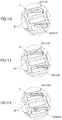
- FIG. 10 shows an example of an elastic piece 3A3 having a plate thickness larger than that of the elastic piece 3A1
- FIG. 11 shows an example of an elastic piece 3A4 having a plate length smaller than that of the elastic piece 3A1
- FIG. 12 shows an example of an elastic piece 3A5 having a shape different from that of the elastic piece 3A1.
- the pressing positions of the plurality of elastic pieces 3A in the above-described embodiment at which the elastic pieces 3A press the lower surface 10b of the electronic control component 10 are arranged such that, when projected in a vertical direction Z relative to a plane orthogonal to the vertical direction Z, the four elastic pieces 3A have rotational symmetry on the plane of projection (see FIG. 5 ).
- FIG. 5 is not a projection drawing
- the elastic pieces 3A are illustrated in a plan view in the same manner as in the case of the plane of projection.
- the pressing positions of the plurality of elastic pieces 3A may be dispersed such that the elastic pieces 3A do not have rotational symmetry and/or line symmetry on the above-described plane of projection (see FIG. 13 ).
- the imbalanced pressing positions make it possible to form a support configuration for the electronic control component 10 that produces undulation, as in the case of the above-described embodiment. Accordingly, it is possible to cause differences in the pressing reaction forces and the amplitudes of the individual elastic pieces 3A, thus reducing the acceleration that is increased at a specific frequency.
Landscapes
- Engineering & Computer Science (AREA)
- General Engineering & Computer Science (AREA)
- Mechanical Engineering (AREA)
- Automation & Control Theory (AREA)
- Aviation & Aerospace Engineering (AREA)
- Physics & Mathematics (AREA)
- Acoustics & Sound (AREA)
- Microelectronics & Electronic Packaging (AREA)
- Mounting Components In General For Electric Apparatus (AREA)
- Casings For Electric Apparatus (AREA)
- Vibration Prevention Devices (AREA)
- Insertion Pins And Rivets (AREA)
- Connection Of Plates (AREA)
Description
- This invention relates to an electronic control component bracket for assembling an electronic control component such as an ECU to a vehicle body side.
- For example, an ECU (Electronic Control Unit) of a vehicle contains a circuit board inside a casing (ECU case), and is attached to a panel member on the vehicle body side by using a bracket according to the preamble of the independent claim 1 (Japanese Laid-Open Patent Publication No.
2006-220171 - Such a bracket absorbs traveling vibration of the vehicle by utilizing pressing with elastic pieces, and functions to suppress the acceleration (vibration frequency) applied to the ECU by the traveling vibration. This makes it possible to prevent a contact failure of a connector of the electronic control component. However, even in such a situation where the acceleration (vibration frequency) is suppressed, there is a possibility that the acceleration may be increased in a specific frequency band.
- An object of this invention is to provide an electronic control component bracket that is less likely to cause a high acceleration (high-speed vibration).
- In order to solve the above-described problem, an electronic control component bracket according to this invention is an electronic control component bracket for assembling an electronic control component to a vehicle body side, the electronic control component bracket including:
- a bottom portion that is to be disposed on a lower surface side of the electronic control component, and on which a plurality of elastic pieces configured to press the lower surface upward are provided; and
- abutting stop portions configured to abut, from above, against the electronic control component that is pressed upward, wherein,
- when vibration is applied in an assembled state in which the electronic control component is clamped between the elastic pieces and the abutting stop portions, one or both of an amplitude and a vibration period, in a vertical direction, of one elastic piece are set to be different from those of at least another elastic piece.
- It is noted that, in the electronic control component of this invention, the side that is pressed to the elastic pieces when the electronic control component bracket is assembled is defined as the lower surface side (lower side), and the side that is abutted and stopped by the abutting stop portion is defined as the upper side.
- According to a conventional configuration, a plurality of elastic pieces are provided as stabilizers on the electronic control component bracket in order to reduce the acceleration (vibration) of the electronic control component, and the elastic pieces hold the electronic control component in a pressing state. However, those elastic pieces all have the same shape and the same pressing reaction force, and press the electronic control component in a well-balanced manner. This good balance, in fact, leads to the matching of the frequency bands in which the acceleration (vibration frequency) is increased in the individual elastic pieces, resulting in a further increased acceleration in the matching frequency band. According to the above-described configuration of this invention, the amplitude and the vibration period of at least one of the plurality of elastic pieces are set to be different from those of the other elastic pieces. That is, the supports for the electronic control component provided by the plurality of elastic pieces are intentionally made imbalanced. Accordingly, the acceleration will not be increased in a specific frequency band in such a form that the individual elastic pieces resonate. That is, the acceleration peaks in the individual elastic pieces are dispersed, whereby the peak can be lowered.
- The above-described plurality of elastic pieces of this invention may be provided such that at least one elastic piece has a larger pressing reaction force for pressing the lower surface than another elastic piece. With this configuration, the frequency bands in which the acceleration is increased in the individual elastic pieces are dispersed, so that an extremely large acceleration will not be generated in a specific frequency band. Specifically, the above-described plurality of elastic pieces of this invention are provided such that one or more of a plate thickness, a plate width, a plate length, and a shape of at least one elastic piece are different from those of other elastic pieces, whereby the elastic pieces can have different pressing reaction forces.
- In the above-described plurality of elastic pieces of this invention, pressing positions of the plurality of elastic pieces at which the elastic pieces press the lower surface may be dispersed so as not to have rotational symmetry and line symmetry within the lower surface. In the case of the conventional configuration, in addition to having the same shape and the same pressing reaction force, the plurality of elastic pieces are disposed so as to have symmetry. Therefore, there is a possibility that an extremely large acceleration may be generated in a specific frequency band. According to the above-described configuration, no symmetry occurs in the arrangement of the plurality of elastic pieces, and, therefore, the frequency bands in which the acceleration is increased in the individual elastic pieces can be dispersed.
-
-
FIG. 1 is a perspective view showing a state in which an ECU is assembled to an ECU bracket according to an embodiment of this invention; -
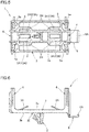
FIG. 2 is a plan view ofFIG. 1 ; -
FIG. 3 is a front view ofFIG. 1 ; -
FIG. 4 is a perspective view of the ECU bracket shown inFIG. 1 ; -
FIG. 5 is a plan view ofFIG. 4 ; -
FIG. 6 is a front view ofFIG. 4 ; -
FIG. 7 is a plan view of a conventional ECU bracket; -
FIG. 8 is an explanatory diagram showing the accelerations of an ECU in various frequency bands when the ECU is assembled to the conventional ECU bracket and vibration is applied to the ECU; -
FIG. 9 is an explanatory diagram showing the accelerations of an ECU in various frequency bands when the ECU is assembled to the ECU bracket of this invention and vibration is applied to the ECU; -
FIG. 10 is an enlarged view showing a first modification of the ECU bracket shown inFIG. 1 ; -
FIG. 11 is an enlarged view showing a second modification of the ECU bracket shown inFIG. 1 ; -
FIG. 12 is an enlarged view showing a third modification of the ECU bracket shown inFIG. 1 ; and -
FIG. 13 is a plan view showing a fourth modification of the ECU bracket shown inFIG. 1 . - An embodiment of this invention will be described with reference to the drawings.
- As shown in
FIGS. 1 to 3 , an electroniccontrol component bracket 1 of this embodiment includes: first and secondengaging portions 2, 6 (engaging portions: seeFIG. 3 ) for assembling anelectronic control component 10 to a vehicle body side; abottom portion 3 that is to be disposed on alower surface 10b side of theelectronic control component 10 and on which a plurality ofelastic pieces 3A configured to press thelower surface 10b upward are provided;side wall portions bottom portion 3; and abuttingstop portions 5 that extend from upper ends of theside wall portions 4 so as to overlap to theupper surface 10a side. Theelectronic control component 10 is disposed on thebottom portion 3 so as to be sandwiched between the twoside wall portions control component bracket 1, and is brought into an assembled state in which theelectronic control component 10 is clamped by being sandwiched by theelastic pieces 3A and theabutting stop portions 5. - As shown in
FIG. 3 , the firstengaging portion 2 here is formed so as to protrude from aback surface 3b on the side, of thebottom portion 3, that is opposite to amain front surface 3a side on which theelectronic control component 10 is disposed. The firstengaging portion 2 here is an insertion engaging portion that is to be inserted to afirst fixing hole 102H of apanel member 100 on the vehicle body side, and that is to be engaged with and fixed to a peripheral portion of thefixing hole 102H so as to be latched to the peripheral portion at the inserted location. It is noted that the firstengaging portion 2 is not limited to the one described in this embodiment, and may be assembled to the vehicle body side in a different shape by a different engaging method. - The second
engaging portion 6 here has an arm shape extending downward from theback surface 3b of thebottom portion 3 and being bent so as to be substantially parallel to thebottom portion 3 at the extension location, and is formed as an elastic arm whose distal end side is elastically deformable in a vertical direction. The secondengaging portion 6 here is a go-around engaging portion configured such that, when inserted to asecond fixing hole 106H of thepanel member 100 on the vehicle body side, the distal end side of the engaging portion goes around to the back side of thepanel member 100, and adistal end portion 6A is latched to (comes into contact with) the back surface of thepanel member 100. When thedistal end portion 6A comes into contact with the back surface of thepanel member 100, the second engagingportion 6 undergoes elastic deformation in a direction in which thedistal end portion 6A side moves away from the back surface of thepanel member 100, and thedistal end portion 6A presses thepanel member 100 from the back surface side to the front side. - When the first and second
engaging portions panel member 100, first, the secondengaging portion 6 is passed through thesecond fixing hole 106H of thepanel member 100. Thereafter, the firstengaging portion 2 is passed through thefirst fixing hole 102H of thepanel member 100. This brings about a state in which the firstengaging portion 2 is inserted and latched to thefirst fixing hole 102H while thedistal end portion 6A of the second engagingportion 6 presses thepanel member 100 from the back surface side to the front side, thus bringing about a state in which the front surface of thepanel member 100 abuts against anabutting portion 30 protruding downward from thebottom portion 3, or in other words, a state in which the first and secondengaging portions panel member 100. - In the
bottom portion 3, themain front surface 3a is disposed so as to oppose thelower surface 10b side of theelectronic control component 10. The plurality ofelastic pieces 3A configured to press thelower surface 10b upward are provided on thebottom portion 3. As shown inFIGS. 4 to 6 , each of theelastic pieces 3A here extends obliquely upward in a cantilevered manner above a throughhole 3H vertically extending through thebottom portion 3, with a peripheral portion of the throughhole 3H as the proximal end side, and theelastic piece 3A is configured to be elastically deformable in the vertical direction, with the distal end side of theelastic piece 3A as a free end. When theelectronic control component 10 has been assembled to the electroniccontrol component bracket 1, theelastic pieces 3A are maintained in a state in which theelastic pieces 3A constantly press theelectronic control component 10 upward by being bent downward (seeFIG. 3 ) . - The
side wall portions side wall portions FIGS. 4 to 6 , theabutting stop portions side wall portions inclined surfaces 5a extending downward toward the inner side in the opposing direction. When theelectronic control component 10 is assembled, theelectronic control component 10 presses theside wall portions side wall portions inclined surfaces 5a downward, and enters the space between the opposingside wall portions side wall portions portions electronic control component 10 from above. The abutting stopportions upper surface 10a of theelectronic control component 10 from above. - Meanwhile, the plurality of
elastic pieces 3A of this embodiment are provided such that, when vibration contained in the traveling vibration of the vehicle is applied in an assembled state in which theelectronic control component 10 has been assembled to the electroniccontrol component bracket 1 in a clamped state, the amplitude and the vibration period of at least one elastic piece 3A1 are different from those of the other elastic pieces 3A2. - The elastic pieces 3A2 here are provided so as to have a larger pressing reaction force for pressing the
lower surface 10b of theelectronic control component 10 than the other elastic pieces 3A1. Specifically, theelastic pieces 3A are composed of two elastic pieces 3A1 and two elastic pieces 3A2, and the plate width of the elastic pieces 3A2 is different from the plate width of the elastic pieces 3A1. This difference in the plate width makes a difference in the pressing reaction force, and hence a difference in one of the amplitude and the vibration period. When projected in a vertical direction Z to a plane orthogonal to the vertical direction Z, the fourelastic pieces 3A here are provided, on the plane of projection, with two narrow-width elastic pieces 3A1 in a first diagonal direction and two wide-width elastic pieces 3A2 in a second diagonal direction, relative to the substantially rectangular mainfront surface 3a (seeFIG. 5 ). It is noted that, althoughFIG. 5 is not a projection drawing, theelastic pieces 3A are illustrated in a plan view in the same manner as in the case of the plane of projection. - In this manner, by including, among the plurality of
elastic pieces 3A, an elastic piece having a different amplitude or a different vibration period when vibration is applied, theelectronic control component 10 in the above-described assembled state causes vibration having an undulating configuration (a large amplitude on the elastic piece 3A1 side, and a small amplitude on the elastic piece 3A2 side). However, such an imbalanced support configuration that allows undulation can be considered to be a configuration that varies the frequency bands in which the acceleration (vibration frequency) is increased in the individualelastic pieces 3A. That is, this imbalanced support configuration is a configuration in which the frequency bands in which the acceleration is increased in the individual elastic pieces are dispersed. Accordingly, an excessively large acceleration will not be caused in a specific frequency band by resonance. -
FIG. 7 shows a conventional electronic control component bracket 1000. The same elements that constitute the above-described embodiment are denoted by the same reference numerals. In the previously described electronic control component bracket 1 (seeFIG. 4 ) of this invention, there is a difference in plate width between the elastic pieces 3A1, 3A2. However, in the electronic control component bracket 1000 shown inFIG. 7 , four elastic pieces 3A0 (3A) are the same, all in plate width, plate thickness, plate length, and shape.FIG. 8 shows the result of examining the accelerations at various frequencies in the conventional electronic control component bracket 1000 by attaching an acceleration sensor to a connector portion of theelectronic control component 10 and vibrating theelectronic control component 10 on a vibration platform. On the other hand,FIG. 9 shows the result of examining the accelerations at various frequencies in the same manner in an assembled state in which theelectronic control component 10 has been assembled in a clamped state to the electroniccontrol component bracket 1 of this embodiment. The acceleration peak that is increased in the range from 50 to 60 Hz inFIG. 8 is lowered inFIG. 9 . That is, it can be seen that, in this embodiment, the acceleration that is increased at a specific frequency is significantly suppressed than in the case of the conventional electronic control component bracket, and is below a prescribed value (indicated by the broken lines in the drawings). - Although the embodiment of this invention has been described above, the embodiment is merely illustrative, and this invention is not limited thereto. Various modifications such as additions and omissions may be made based on the knowledge of a person skilled in the art provided that said modifications fall within the scope of the invention, which is defined by the appended claims.
- In the following, other embodiments different from the above-described embodiment, and modifications will be described. It is noted that parts having the same functions as those in the above-described embodiment are denoted by the same reference numerals, and the detailed description thereof is omitted. The above-described embodiment and the following examples may be combined to be implemented as appropriate as long as no technical contradiction arises.
- The plurality of
elastic pieces 3A in the above-described embodiment include an elastic piece 3A2 having a difference in plate width from at least one elastic piece 3A1. However, as shown inFIGS. 10 to 12 , theelastic pieces 3A may be provided such that one or more of the plate width, the plate thickness, the plate length, and the shape of at least one elastic piece 3A1 are different from those of the other elastic pieces 3A3, 3A4, 3A5. Specifically,FIG. 10 shows an example of an elastic piece 3A3 having a plate thickness larger than that of the elastic piece 3A1,FIG. 11 shows an example of an elastic piece 3A4 having a plate length smaller than that of the elastic piece 3A1, andFIG. 12 shows an example of an elastic piece 3A5 having a shape different from that of the elastic piece 3A1. - The pressing positions of the plurality of
elastic pieces 3A in the above-described embodiment at which theelastic pieces 3A press thelower surface 10b of theelectronic control component 10 are arranged such that, when projected in a vertical direction Z relative to a plane orthogonal to the vertical direction Z, the fourelastic pieces 3A have rotational symmetry on the plane of projection (seeFIG. 5 ). It is noted that, althoughFIG. 5 is not a projection drawing, theelastic pieces 3A are illustrated in a plan view in the same manner as in the case of the plane of projection. However, the pressing positions of the plurality ofelastic pieces 3A may be dispersed such that theelastic pieces 3A do not have rotational symmetry and/or line symmetry on the above-described plane of projection (seeFIG. 13 ). In this case, even if the plurality ofelastic pieces 3A are the same, all in plate width, plate thickness, plate length, and shape, the imbalanced pressing positions make it possible to form a support configuration for theelectronic control component 10 that produces undulation, as in the case of the above-described embodiment. Accordingly, it is possible to cause differences in the pressing reaction forces and the amplitudes of the individualelastic pieces 3A, thus reducing the acceleration that is increased at a specific frequency. -
- 1 electronic control component bracket
- 10 electronic control component
- 10a upper surface of electronic control component
- 10b lower surface of electronic control component
- 2 engaging portion
- 3 bottom portion
- 3a main front surface of bottom portion
- 3A elastic piece
- 4 side wall portion
- 5 abutting stop portion
- 5a inclined surface
Claims (4)
- An electronic control component bracket (1) for assembling an electronic control component (10) to a vehicle body (100) side, the electronic control component bracket comprising:a bottom portion (3) that is to be disposed on a lower surface (10b) side of the electronic control component (10), and on which a plurality of elastic pieces (3A) configured to press the lower surface (10b) upward are provided; andabutting stop portions (5) configured to abut, from above, against the electronic control component (10) that is pressed upward, characterized in that the plurality of elastic pieces (3A) are configured so thatwhen vibration is applied in an assembled state in which the electronic control component (10) is clamped between the elastic pieces (3A) and the abutting stop portions (5), one or both of an amplitude and a vibration period, in a vertical direction, of one elastic piece (3A1) are set to be different from those of at least another elastic piece (3A2).
- The electronic control component bracket (1) according to claim 1, wherein
the plurality of elastic pieces (3A) are provided such that at least one elastic piece (3A2) has a larger pressing reaction force for pressing the lower surface (10b) than the other elastic piece (3A2). - The electronic control component bracket (1) according to claim 2, wherein
the plurality of elastic pieces (3A) are provided such that one or more of a plate thickness, a plate width, a plate length, and a shape of at least one elastic piece (3A1) are different from those of other elastic pieces (3A2, 3A3, 3A4, 3A5). - The electronic control component bracket (1) according to any one of claims 1 to 3, wherein,
pressing positions of the plurality of elastic pieces (3A) at which the elastic pieces (3A) press the lower surface (10b) are dispersed so as not to have rotational symmetry and line symmetry within the lower surface (10b).
Applications Claiming Priority (1)
| Application Number | Priority Date | Filing Date | Title |
|---|---|---|---|
| JP2018238092A JP7252752B2 (en) | 2018-12-20 | 2018-12-20 | Bracket for electronic control parts |
Publications (2)
| Publication Number | Publication Date |
|---|---|
| EP3675609A1 EP3675609A1 (en) | 2020-07-01 |
| EP3675609B1 true EP3675609B1 (en) | 2021-06-23 |
Family
ID=68653346
Family Applications (1)
| Application Number | Title | Priority Date | Filing Date |
|---|---|---|---|
| EP19210628.4A Active EP3675609B1 (en) | 2018-12-20 | 2019-11-21 | Electronic control component bracket |
Country Status (4)
| Country | Link |
|---|---|
| US (2) | US11654843B2 (en) |
| EP (1) | EP3675609B1 (en) |
| JP (3) | JP7252752B2 (en) |
| CN (1) | CN111497761B (en) |
Families Citing this family (5)
| Publication number | Priority date | Publication date | Assignee | Title |
|---|---|---|---|---|
| JP7252752B2 (en) | 2018-12-20 | 2023-04-05 | 大和化成工業株式会社 | Bracket for electronic control parts |
| CN112153848B (en) * | 2020-08-31 | 2021-12-17 | 南京坤前计算机科技有限公司 | Tray structure with folding and shock-absorbing functions and server cabinet |
| JP2024101096A (en) | 2023-01-17 | 2024-07-29 | 大和化成工業株式会社 | Brackets for electronic control components |
| FR3147164B1 (en) * | 2023-03-30 | 2025-02-14 | Psa Automobiles Sa | HEAT OBJECT SUPPORT FOR MOTOR VEHICLE AND MOTOR VEHICLE EQUIPPED WITH SUCH A SUPPORT |
| US20250047086A1 (en) * | 2023-08-03 | 2025-02-06 | Frontier Communications Holdings, Llc | Locking Apparatus for Outdoor Network Terminal |
Family Cites Families (50)
| Publication number | Priority date | Publication date | Assignee | Title |
|---|---|---|---|---|
| US1181173A (en) * | 1915-05-15 | 1916-05-02 | Frederick Schubert | Gage. |
| US2873082A (en) * | 1955-03-11 | 1959-02-10 | Borg Warner | Clip |
| US3058714A (en) * | 1960-01-25 | 1962-10-16 | Northrop Corp | Resistor mounting bracket |
| US3160280A (en) * | 1963-08-12 | 1964-12-08 | Gen Electric | Device for mounting apparatus |
| FR1501968A (en) * | 1966-09-30 | 1967-11-18 | Parisienne D Expansion Chimiqu | Packaging article for object of revolution |
| US3595402A (en) * | 1969-04-16 | 1971-07-27 | Pyle National Co | Modular terminal block mounting rack |
| US3917202A (en) * | 1974-06-24 | 1975-11-04 | Illinois Tool Works | Terminal block mounting bracket |
| JPS5547100Y2 (en) * | 1975-04-07 | 1980-11-05 | ||
| US4273399A (en) * | 1979-11-05 | 1981-06-16 | Amp Incorporated | Transducer supporting and contacting means |
| FR2649466B1 (en) * | 1989-07-06 | 1991-09-27 | Peugeot | DEVICE FOR FIXING A SET OF TUBES OR THE LIKE ON A WALL |
| DE9107041U1 (en) * | 1991-06-07 | 1991-11-14 | Emhart Inc., Newark, Del. | Clamp arrangement for pipes and cables |
| US5865413A (en) * | 1995-08-07 | 1999-02-02 | Motorola Inc. | Surface mountable component holder |
| EP0845750A3 (en) * | 1996-11-29 | 2000-11-29 | Tyco Electronics Logistics AG | Double connector for two chip cards |
| DE29706022U1 (en) * | 1997-04-04 | 1997-05-28 | Merkur Stahlwaren GmbH & Co. KG, 42719 Solingen | Hand shaver |
| US6082547A (en) * | 1998-03-27 | 2000-07-04 | Fluoroware, Inc. | Adapter jig |
| JP3682698B2 (en) * | 1999-06-04 | 2005-08-10 | 株式会社パイオラックス | Rod body holder |
| JP3789729B2 (en) | 2000-05-31 | 2006-06-28 | アルプス電気株式会社 | Cover structure of converter for satellite broadcasting reception |
| JP2002010452A (en) * | 2000-06-21 | 2002-01-11 | Yazaki Corp | Support structure of clamp to flat cable |
| US6651827B1 (en) * | 2000-11-02 | 2003-11-25 | Berol Corporation | Brochure holder |
| DE10100831A1 (en) * | 2001-01-10 | 2002-07-11 | Emhart Inc | Conductor holder |
| DE10144153A1 (en) * | 2001-09-07 | 2003-03-27 | Newfrey Llc | Clip for holding groups of pipes or cables has recesses, into which cables fit, walls between these having fingers which slope towards bases of recesses and which are offset so that they do not overlap |
| DE10159277B4 (en) * | 2001-12-04 | 2012-06-06 | Newfrey Llc | Mobile arch holder for elongated objects |
| JP4002812B2 (en) * | 2002-10-08 | 2007-11-07 | 株式会社ニフコ | Clamp |
| US6820753B2 (en) * | 2002-11-21 | 2004-11-23 | Lisle Corporation | Universal disposable glove dispenser bracket |
| JP2004192840A (en) * | 2002-12-09 | 2004-07-08 | Sharp Corp | Equipment with external unit |
| JP2005155749A (en) * | 2003-11-25 | 2005-06-16 | Nifco Inc | Pipe clamp |
| US6950310B2 (en) * | 2003-12-31 | 2005-09-27 | Texas Instruments Incorporated | System and method for self-leveling heat sink for multiple height devices |
| CN2785022Y (en) * | 2005-01-29 | 2006-05-31 | 鸿富锦精密工业(深圳)有限公司 | Data storage device fixing equipment |
| JP4593305B2 (en) * | 2005-02-08 | 2010-12-08 | 大和化成工業株式会社 | bracket |
| JP2007056908A (en) | 2005-08-22 | 2007-03-08 | Toyota Boshoku Corp | Mounting bracket |
| CN2849910Y (en) * | 2005-09-30 | 2006-12-20 | 鸿富锦精密工业(深圳)有限公司 | Fixer for data memory |
| JP4793221B2 (en) * | 2006-11-01 | 2011-10-12 | 株式会社デンソー | Electronic component mounting structure and electronic component mounting method |
| US8408501B2 (en) * | 2008-02-08 | 2013-04-02 | R.A. Phillips Industries, Inc. | Hose clamp for tractor rig |
| JP5133117B2 (en) * | 2008-04-22 | 2013-01-30 | クラリオン株式会社 | Speaker mounting structure and speaker device |
| US20090308987A1 (en) * | 2008-06-17 | 2009-12-17 | Martha Exposito Alexis E Devor | Arcadia stud clip |
| JP4774110B2 (en) * | 2008-07-28 | 2011-09-14 | 日本特殊陶業株式会社 | Circuit board case |
| JP5083098B2 (en) | 2008-07-30 | 2012-11-28 | 株式会社Jvcケンウッド | Speaker frame and speaker unit |
| US7938376B2 (en) * | 2008-08-22 | 2011-05-10 | Control Solutions LLC | Mounting clips and sensor installations for motorized vehicle doors |
| US7856746B1 (en) * | 2008-12-23 | 2010-12-28 | Luis Araujo | Tag clip for labeling tubes, cables and the like |
| JP5408541B2 (en) * | 2009-11-06 | 2014-02-05 | 北川工業株式会社 | Surface mount clip |
| JP2012138474A (en) * | 2010-12-27 | 2012-07-19 | Denso Corp | Electronic device attachment structure |
| CN202301737U (en) | 2011-09-28 | 2012-07-04 | 上海汽车集团股份有限公司 | Vibration isolation type vehicle engine electronic control unit support |
| HRP20160956T1 (en) * | 2011-10-21 | 2016-10-07 | Q-Clip B.V. | PIPE CLAMP |
| US8857613B1 (en) * | 2012-07-12 | 2014-10-14 | Warren Harris | Sample display device |
| US9541223B2 (en) * | 2014-06-30 | 2017-01-10 | Newfrey Llc | Two-shot tube retention pocket tube clamp, mold and process |
| TWI581986B (en) * | 2014-07-24 | 2017-05-11 | Nippon Steel & Sumitomo Metal Corp | Railway vehicles with sound insulation wheels |
| CN106340998B (en) * | 2016-11-15 | 2019-10-18 | 苏州海歌电器科技有限公司 | Motor of dust collector shock-damping structure |
| JP6533248B2 (en) * | 2017-04-21 | 2019-06-19 | 大和化成工業株式会社 | Bracket mounting structure |
| CN107355905A (en) * | 2017-08-24 | 2017-11-17 | 广东美的制冷设备有限公司 | Compressor and there is its refrigerating plant |
| JP7252752B2 (en) * | 2018-12-20 | 2023-04-05 | 大和化成工業株式会社 | Bracket for electronic control parts |
-
2018
- 2018-12-20 JP JP2018238092A patent/JP7252752B2/en active Active
-
2019
- 2019-11-21 EP EP19210628.4A patent/EP3675609B1/en active Active
- 2019-12-03 US US16/701,962 patent/US11654843B2/en active Active
- 2019-12-16 CN CN201911293943.7A patent/CN111497761B/en active Active
-
2023
- 2023-03-23 JP JP2023046872A patent/JP7584202B2/en active Active
- 2023-04-04 US US18/295,479 patent/US12252080B2/en active Active
-
2024
- 2024-10-30 JP JP2024190662A patent/JP7681175B2/en active Active
Non-Patent Citations (1)
| Title |
|---|
| None * |
Also Published As
| Publication number | Publication date |
|---|---|
| JP7584202B2 (en) | 2024-11-15 |
| US20230242053A1 (en) | 2023-08-03 |
| US20200198560A1 (en) | 2020-06-25 |
| JP2025014037A (en) | 2025-01-28 |
| CN111497761B (en) | 2023-08-22 |
| CN111497761A (en) | 2020-08-07 |
| JP2020102480A (en) | 2020-07-02 |
| EP3675609A1 (en) | 2020-07-01 |
| JP2023085368A (en) | 2023-06-20 |
| US11654843B2 (en) | 2023-05-23 |
| JP7681175B2 (en) | 2025-05-21 |
| JP7252752B2 (en) | 2023-04-05 |
| US12252080B2 (en) | 2025-03-18 |
Similar Documents
| Publication | Publication Date | Title |
|---|---|---|
| EP3675609B1 (en) | Electronic control component bracket | |
| JP4186826B2 (en) | PCB mounting structure | |
| US9120509B2 (en) | Hole plug | |
| JP5874513B2 (en) | Board fixing structure | |
| JP5658491B2 (en) | Electronic device storage case | |
| TWI712227B (en) | Floating connector and connecting mechanism assembly | |
| US9748731B2 (en) | Optical apparatus | |
| US20240409046A1 (en) | Electronic control component bracket | |
| US12356563B2 (en) | Electronic control component bracket | |
| JP5065226B2 (en) | Electronic circuit board housing case | |
| JP4495230B2 (en) | Electrical connector and electrical connector unit including the same | |
| JP2016203734A (en) | Part fixing structure | |
| JP6386504B2 (en) | Name plate mounting structure | |
| JP6614874B2 (en) | Electronic equipment case | |
| JP7609107B2 (en) | Circuit board fixing structure | |
| JP5459233B2 (en) | Electronic equipment | |
| WO2018198520A1 (en) | Case and electronic device | |
| US11825616B2 (en) | Vehicle-mounted electronic apparatus | |
| JP2008208852A (en) | Fitting member and assembly | |
| KR100683224B1 (en) | Assembly structure of circuit board | |
| JP2024171749A (en) | Display panel storage structure, electronic device, and display panel storage method | |
| JP2017004998A (en) | On-vehicle electronic apparatus | |
| CN117090805A (en) | Component installation structure and component installation method | |
| WO2022162837A1 (en) | Vibration measurement device | |
| JP2022122488A (en) | Anchor structure and harness protection tool |
Legal Events
| Date | Code | Title | Description |
|---|---|---|---|
| PUAI | Public reference made under article 153(3) epc to a published international application that has entered the european phase |
Free format text: ORIGINAL CODE: 0009012 |
|
| STAA | Information on the status of an ep patent application or granted ep patent |
Free format text: STATUS: REQUEST FOR EXAMINATION WAS MADE |
|
| 17P | Request for examination filed |
Effective date: 20191121 |
|
| AK | Designated contracting states |
Kind code of ref document: A1 Designated state(s): AL AT BE BG CH CY CZ DE DK EE ES FI FR GB GR HR HU IE IS IT LI LT LU LV MC MK MT NL NO PL PT RO RS SE SI SK SM TR |
|
| AX | Request for extension of the european patent |
Extension state: BA ME |
|
| RIC1 | Information provided on ipc code assigned before grant |
Ipc: H05K 5/02 20060101ALI20201126BHEP Ipc: H05K 5/00 20060101AFI20201126BHEP |
|
| GRAP | Despatch of communication of intention to grant a patent |
Free format text: ORIGINAL CODE: EPIDOSNIGR1 |
|
| STAA | Information on the status of an ep patent application or granted ep patent |
Free format text: STATUS: GRANT OF PATENT IS INTENDED |
|
| INTG | Intention to grant announced |
Effective date: 20210104 |
|
| INTG | Intention to grant announced |
Effective date: 20210113 |
|
| GRAS | Grant fee paid |
Free format text: ORIGINAL CODE: EPIDOSNIGR3 |
|
| GRAA | (expected) grant |
Free format text: ORIGINAL CODE: 0009210 |
|
| STAA | Information on the status of an ep patent application or granted ep patent |
Free format text: STATUS: THE PATENT HAS BEEN GRANTED |
|
| AK | Designated contracting states |
Kind code of ref document: B1 Designated state(s): AL AT BE BG CH CY CZ DE DK EE ES FI FR GB GR HR HU IE IS IT LI LT LU LV MC MK MT NL NO PL PT RO RS SE SI SK SM TR |
|
| RAP3 | Party data changed (applicant data changed or rights of an application transferred) |
Owner name: DAIWA KASEI INDUSTRY CO., LTD. Owner name: TOYOTA JIDOSHA KABUSHIKI KAISHA |
|
| REG | Reference to a national code |
Ref country code: GB Ref legal event code: FG4D |
|
| RIN1 | Information on inventor provided before grant (corrected) |
Inventor name: UKAI, JUNYA Inventor name: KATO, MAKOTO Inventor name: TAKATA, KAZUNORI |
|
| REG | Reference to a national code |
Ref country code: CH Ref legal event code: EP |
|
| REG | Reference to a national code |
Ref country code: DE Ref legal event code: R096 Ref document number: 602019005580 Country of ref document: DE Ref country code: AT Ref legal event code: REF Ref document number: 1405447 Country of ref document: AT Kind code of ref document: T Effective date: 20210715 |
|
| REG | Reference to a national code |
Ref country code: IE Ref legal event code: FG4D |
|
| REG | Reference to a national code |
Ref country code: LT Ref legal event code: MG9D |
|
| PG25 | Lapsed in a contracting state [announced via postgrant information from national office to epo] |
Ref country code: HR Free format text: LAPSE BECAUSE OF FAILURE TO SUBMIT A TRANSLATION OF THE DESCRIPTION OR TO PAY THE FEE WITHIN THE PRESCRIBED TIME-LIMIT Effective date: 20210623 Ref country code: LT Free format text: LAPSE BECAUSE OF FAILURE TO SUBMIT A TRANSLATION OF THE DESCRIPTION OR TO PAY THE FEE WITHIN THE PRESCRIBED TIME-LIMIT Effective date: 20210623 Ref country code: FI Free format text: LAPSE BECAUSE OF FAILURE TO SUBMIT A TRANSLATION OF THE DESCRIPTION OR TO PAY THE FEE WITHIN THE PRESCRIBED TIME-LIMIT Effective date: 20210623 Ref country code: BG Free format text: LAPSE BECAUSE OF FAILURE TO SUBMIT A TRANSLATION OF THE DESCRIPTION OR TO PAY THE FEE WITHIN THE PRESCRIBED TIME-LIMIT Effective date: 20210923 |
|
| REG | Reference to a national code |
Ref country code: AT Ref legal event code: MK05 Ref document number: 1405447 Country of ref document: AT Kind code of ref document: T Effective date: 20210623 |
|
| PG25 | Lapsed in a contracting state [announced via postgrant information from national office to epo] |
Ref country code: SE Free format text: LAPSE BECAUSE OF FAILURE TO SUBMIT A TRANSLATION OF THE DESCRIPTION OR TO PAY THE FEE WITHIN THE PRESCRIBED TIME-LIMIT Effective date: 20210623 Ref country code: RS Free format text: LAPSE BECAUSE OF FAILURE TO SUBMIT A TRANSLATION OF THE DESCRIPTION OR TO PAY THE FEE WITHIN THE PRESCRIBED TIME-LIMIT Effective date: 20210623 Ref country code: NO Free format text: LAPSE BECAUSE OF FAILURE TO SUBMIT A TRANSLATION OF THE DESCRIPTION OR TO PAY THE FEE WITHIN THE PRESCRIBED TIME-LIMIT Effective date: 20210923 Ref country code: LV Free format text: LAPSE BECAUSE OF FAILURE TO SUBMIT A TRANSLATION OF THE DESCRIPTION OR TO PAY THE FEE WITHIN THE PRESCRIBED TIME-LIMIT Effective date: 20210623 Ref country code: GR Free format text: LAPSE BECAUSE OF FAILURE TO SUBMIT A TRANSLATION OF THE DESCRIPTION OR TO PAY THE FEE WITHIN THE PRESCRIBED TIME-LIMIT Effective date: 20210924 |
|
| REG | Reference to a national code |
Ref country code: NL Ref legal event code: MP Effective date: 20210623 |
|
| PG25 | Lapsed in a contracting state [announced via postgrant information from national office to epo] |
Ref country code: SM Free format text: LAPSE BECAUSE OF FAILURE TO SUBMIT A TRANSLATION OF THE DESCRIPTION OR TO PAY THE FEE WITHIN THE PRESCRIBED TIME-LIMIT Effective date: 20210623 Ref country code: NL Free format text: LAPSE BECAUSE OF FAILURE TO SUBMIT A TRANSLATION OF THE DESCRIPTION OR TO PAY THE FEE WITHIN THE PRESCRIBED TIME-LIMIT Effective date: 20210623 Ref country code: PT Free format text: LAPSE BECAUSE OF FAILURE TO SUBMIT A TRANSLATION OF THE DESCRIPTION OR TO PAY THE FEE WITHIN THE PRESCRIBED TIME-LIMIT Effective date: 20211025 Ref country code: RO Free format text: LAPSE BECAUSE OF FAILURE TO SUBMIT A TRANSLATION OF THE DESCRIPTION OR TO PAY THE FEE WITHIN THE PRESCRIBED TIME-LIMIT Effective date: 20210623 Ref country code: CZ Free format text: LAPSE BECAUSE OF FAILURE TO SUBMIT A TRANSLATION OF THE DESCRIPTION OR TO PAY THE FEE WITHIN THE PRESCRIBED TIME-LIMIT Effective date: 20210623 Ref country code: AT Free format text: LAPSE BECAUSE OF FAILURE TO SUBMIT A TRANSLATION OF THE DESCRIPTION OR TO PAY THE FEE WITHIN THE PRESCRIBED TIME-LIMIT Effective date: 20210623 Ref country code: EE Free format text: LAPSE BECAUSE OF FAILURE TO SUBMIT A TRANSLATION OF THE DESCRIPTION OR TO PAY THE FEE WITHIN THE PRESCRIBED TIME-LIMIT Effective date: 20210623 Ref country code: ES Free format text: LAPSE BECAUSE OF FAILURE TO SUBMIT A TRANSLATION OF THE DESCRIPTION OR TO PAY THE FEE WITHIN THE PRESCRIBED TIME-LIMIT Effective date: 20210623 Ref country code: SK Free format text: LAPSE BECAUSE OF FAILURE TO SUBMIT A TRANSLATION OF THE DESCRIPTION OR TO PAY THE FEE WITHIN THE PRESCRIBED TIME-LIMIT Effective date: 20210623 |
|
| PG25 | Lapsed in a contracting state [announced via postgrant information from national office to epo] |
Ref country code: PL Free format text: LAPSE BECAUSE OF FAILURE TO SUBMIT A TRANSLATION OF THE DESCRIPTION OR TO PAY THE FEE WITHIN THE PRESCRIBED TIME-LIMIT Effective date: 20210623 |
|
| REG | Reference to a national code |
Ref country code: DE Ref legal event code: R097 Ref document number: 602019005580 Country of ref document: DE |
|
| PG25 | Lapsed in a contracting state [announced via postgrant information from national office to epo] |
Ref country code: DK Free format text: LAPSE BECAUSE OF FAILURE TO SUBMIT A TRANSLATION OF THE DESCRIPTION OR TO PAY THE FEE WITHIN THE PRESCRIBED TIME-LIMIT Effective date: 20210623 |
|
| PLBE | No opposition filed within time limit |
Free format text: ORIGINAL CODE: 0009261 |
|
| STAA | Information on the status of an ep patent application or granted ep patent |
Free format text: STATUS: NO OPPOSITION FILED WITHIN TIME LIMIT |
|
| 26N | No opposition filed |
Effective date: 20220324 |
|
| PG25 | Lapsed in a contracting state [announced via postgrant information from national office to epo] |
Ref country code: AL Free format text: LAPSE BECAUSE OF FAILURE TO SUBMIT A TRANSLATION OF THE DESCRIPTION OR TO PAY THE FEE WITHIN THE PRESCRIBED TIME-LIMIT Effective date: 20210623 |
|
| PG25 | Lapsed in a contracting state [announced via postgrant information from national office to epo] |
Ref country code: MC Free format text: LAPSE BECAUSE OF FAILURE TO SUBMIT A TRANSLATION OF THE DESCRIPTION OR TO PAY THE FEE WITHIN THE PRESCRIBED TIME-LIMIT Effective date: 20210623 |
|
| PG25 | Lapsed in a contracting state [announced via postgrant information from national office to epo] |
Ref country code: LU Free format text: LAPSE BECAUSE OF NON-PAYMENT OF DUE FEES Effective date: 20211121 Ref country code: IT Free format text: LAPSE BECAUSE OF FAILURE TO SUBMIT A TRANSLATION OF THE DESCRIPTION OR TO PAY THE FEE WITHIN THE PRESCRIBED TIME-LIMIT Effective date: 20210623 Ref country code: BE Free format text: LAPSE BECAUSE OF NON-PAYMENT OF DUE FEES Effective date: 20211130 |
|
| REG | Reference to a national code |
Ref country code: BE Ref legal event code: MM Effective date: 20211130 |
|
| PG25 | Lapsed in a contracting state [announced via postgrant information from national office to epo] |
Ref country code: IE Free format text: LAPSE BECAUSE OF NON-PAYMENT OF DUE FEES Effective date: 20211121 |
|
| PG25 | Lapsed in a contracting state [announced via postgrant information from national office to epo] |
Ref country code: CY Free format text: LAPSE BECAUSE OF FAILURE TO SUBMIT A TRANSLATION OF THE DESCRIPTION OR TO PAY THE FEE WITHIN THE PRESCRIBED TIME-LIMIT Effective date: 20210623 |
|
| REG | Reference to a national code |
Ref country code: CH Ref legal event code: PL |
|
| PG25 | Lapsed in a contracting state [announced via postgrant information from national office to epo] |
Ref country code: LI Free format text: LAPSE BECAUSE OF NON-PAYMENT OF DUE FEES Effective date: 20221130 Ref country code: HU Free format text: LAPSE BECAUSE OF FAILURE TO SUBMIT A TRANSLATION OF THE DESCRIPTION OR TO PAY THE FEE WITHIN THE PRESCRIBED TIME-LIMIT; INVALID AB INITIO Effective date: 20191121 Ref country code: CH Free format text: LAPSE BECAUSE OF NON-PAYMENT OF DUE FEES Effective date: 20221130 |
|
| PGFP | Annual fee paid to national office [announced via postgrant information from national office to epo] |
Ref country code: GB Payment date: 20231123 Year of fee payment: 5 |
|
| PGFP | Annual fee paid to national office [announced via postgrant information from national office to epo] |
Ref country code: DE Payment date: 20231031 Year of fee payment: 5 |
|
| PG25 | Lapsed in a contracting state [announced via postgrant information from national office to epo] |
Ref country code: MK Free format text: LAPSE BECAUSE OF FAILURE TO SUBMIT A TRANSLATION OF THE DESCRIPTION OR TO PAY THE FEE WITHIN THE PRESCRIBED TIME-LIMIT Effective date: 20210623 |
|
| PG25 | Lapsed in a contracting state [announced via postgrant information from national office to epo] |
Ref country code: TR Free format text: LAPSE BECAUSE OF FAILURE TO SUBMIT A TRANSLATION OF THE DESCRIPTION OR TO PAY THE FEE WITHIN THE PRESCRIBED TIME-LIMIT Effective date: 20210623 |
|
| PG25 | Lapsed in a contracting state [announced via postgrant information from national office to epo] |
Ref country code: MT Free format text: LAPSE BECAUSE OF FAILURE TO SUBMIT A TRANSLATION OF THE DESCRIPTION OR TO PAY THE FEE WITHIN THE PRESCRIBED TIME-LIMIT Effective date: 20210623 |
|
| REG | Reference to a national code |
Ref country code: DE Ref legal event code: R119 Ref document number: 602019005580 Country of ref document: DE |
|
| GBPC | Gb: european patent ceased through non-payment of renewal fee |
Effective date: 20241121 |
|
| PG25 | Lapsed in a contracting state [announced via postgrant information from national office to epo] |
Ref country code: DE Free format text: LAPSE BECAUSE OF NON-PAYMENT OF DUE FEES Effective date: 20250603 |
|
| PG25 | Lapsed in a contracting state [announced via postgrant information from national office to epo] |
Ref country code: GB Free format text: LAPSE BECAUSE OF NON-PAYMENT OF DUE FEES Effective date: 20241121 |
|
| PGFP | Annual fee paid to national office [announced via postgrant information from national office to epo] |
Ref country code: FR Payment date: 20251125 Year of fee payment: 7 |