EP3675485A1 - Surrounding vehicle display method and surrounding vehicle display apparatus - Google Patents
Surrounding vehicle display method and surrounding vehicle display apparatus Download PDFInfo
- Publication number
- EP3675485A1 EP3675485A1 EP17922800.2A EP17922800A EP3675485A1 EP 3675485 A1 EP3675485 A1 EP 3675485A1 EP 17922800 A EP17922800 A EP 17922800A EP 3675485 A1 EP3675485 A1 EP 3675485A1
- Authority
- EP
- European Patent Office
- Prior art keywords
- vehicle
- host vehicle
- virtual image
- surrounding
- display
- Prior art date
- Legal status (The legal status is an assumption and is not a legal conclusion. Google has not performed a legal analysis and makes no representation as to the accuracy of the status listed.)
- Granted
Links
- 238000000034 method Methods 0.000 title claims description 22
- 238000001514 detection method Methods 0.000 abstract description 21
- 238000004364 calculation method Methods 0.000 description 19
- 230000010365 information processing Effects 0.000 description 6
- 238000010586 diagram Methods 0.000 description 3
- 230000000694 effects Effects 0.000 description 3
- 230000006870 function Effects 0.000 description 3
- 238000004590 computer program Methods 0.000 description 2
- 230000001133 acceleration Effects 0.000 description 1
- 230000036461 convulsion Effects 0.000 description 1
- 239000005357 flat glass Substances 0.000 description 1
- 239000004973 liquid crystal related substance Substances 0.000 description 1
Images


Classifications
-
- H—ELECTRICITY
- H04—ELECTRIC COMMUNICATION TECHNIQUE
- H04N—PICTORIAL COMMUNICATION, e.g. TELEVISION
- H04N7/00—Television systems
- H04N7/18—Closed-circuit television [CCTV] systems, i.e. systems in which the video signal is not broadcast
-
- B—PERFORMING OPERATIONS; TRANSPORTING
- B60—VEHICLES IN GENERAL
- B60R—VEHICLES, VEHICLE FITTINGS, OR VEHICLE PARTS, NOT OTHERWISE PROVIDED FOR
- B60R1/00—Optical viewing arrangements; Real-time viewing arrangements for drivers or passengers using optical image capturing systems, e.g. cameras or video systems specially adapted for use in or on vehicles
- B60R1/20—Real-time viewing arrangements for drivers or passengers using optical image capturing systems, e.g. cameras or video systems specially adapted for use in or on vehicles
- B60R1/22—Real-time viewing arrangements for drivers or passengers using optical image capturing systems, e.g. cameras or video systems specially adapted for use in or on vehicles for viewing an area outside the vehicle, e.g. the exterior of the vehicle
- B60R1/23—Real-time viewing arrangements for drivers or passengers using optical image capturing systems, e.g. cameras or video systems specially adapted for use in or on vehicles for viewing an area outside the vehicle, e.g. the exterior of the vehicle with a predetermined field of view
- B60R1/27—Real-time viewing arrangements for drivers or passengers using optical image capturing systems, e.g. cameras or video systems specially adapted for use in or on vehicles for viewing an area outside the vehicle, e.g. the exterior of the vehicle with a predetermined field of view providing all-round vision, e.g. using omnidirectional cameras
-
- B—PERFORMING OPERATIONS; TRANSPORTING
- B60—VEHICLES IN GENERAL
- B60K—ARRANGEMENT OR MOUNTING OF PROPULSION UNITS OR OF TRANSMISSIONS IN VEHICLES; ARRANGEMENT OR MOUNTING OF PLURAL DIVERSE PRIME-MOVERS IN VEHICLES; AUXILIARY DRIVES FOR VEHICLES; INSTRUMENTATION OR DASHBOARDS FOR VEHICLES; ARRANGEMENTS IN CONNECTION WITH COOLING, AIR INTAKE, GAS EXHAUST OR FUEL SUPPLY OF PROPULSION UNITS IN VEHICLES
- B60K35/00—Arrangement of adaptations of instruments
-
- B—PERFORMING OPERATIONS; TRANSPORTING
- B60—VEHICLES IN GENERAL
- B60R—VEHICLES, VEHICLE FITTINGS, OR VEHICLE PARTS, NOT OTHERWISE PROVIDED FOR
- B60R1/00—Optical viewing arrangements; Real-time viewing arrangements for drivers or passengers using optical image capturing systems, e.g. cameras or video systems specially adapted for use in or on vehicles
- B60R1/20—Real-time viewing arrangements for drivers or passengers using optical image capturing systems, e.g. cameras or video systems specially adapted for use in or on vehicles
- B60R1/22—Real-time viewing arrangements for drivers or passengers using optical image capturing systems, e.g. cameras or video systems specially adapted for use in or on vehicles for viewing an area outside the vehicle, e.g. the exterior of the vehicle
- B60R1/28—Real-time viewing arrangements for drivers or passengers using optical image capturing systems, e.g. cameras or video systems specially adapted for use in or on vehicles for viewing an area outside the vehicle, e.g. the exterior of the vehicle with an adjustable field of view
-
- B—PERFORMING OPERATIONS; TRANSPORTING
- B60—VEHICLES IN GENERAL
- B60R—VEHICLES, VEHICLE FITTINGS, OR VEHICLE PARTS, NOT OTHERWISE PROVIDED FOR
- B60R21/00—Arrangements or fittings on vehicles for protecting or preventing injuries to occupants or pedestrians in case of accidents or other traffic risks
-
- G06T3/02—
-
- G—PHYSICS
- G08—SIGNALLING
- G08G—TRAFFIC CONTROL SYSTEMS
- G08G1/00—Traffic control systems for road vehicles
- G08G1/16—Anti-collision systems
-
- B—PERFORMING OPERATIONS; TRANSPORTING
- B60—VEHICLES IN GENERAL
- B60R—VEHICLES, VEHICLE FITTINGS, OR VEHICLE PARTS, NOT OTHERWISE PROVIDED FOR
- B60R2300/00—Details of viewing arrangements using cameras and displays, specially adapted for use in a vehicle
- B60R2300/30—Details of viewing arrangements using cameras and displays, specially adapted for use in a vehicle characterised by the type of image processing
-
- B—PERFORMING OPERATIONS; TRANSPORTING
- B60—VEHICLES IN GENERAL
- B60R—VEHICLES, VEHICLE FITTINGS, OR VEHICLE PARTS, NOT OTHERWISE PROVIDED FOR
- B60R2300/00—Details of viewing arrangements using cameras and displays, specially adapted for use in a vehicle
- B60R2300/60—Details of viewing arrangements using cameras and displays, specially adapted for use in a vehicle characterised by monitoring and displaying vehicle exterior scenes from a transformed perspective
- B60R2300/602—Details of viewing arrangements using cameras and displays, specially adapted for use in a vehicle characterised by monitoring and displaying vehicle exterior scenes from a transformed perspective with an adjustable viewpoint
- B60R2300/605—Details of viewing arrangements using cameras and displays, specially adapted for use in a vehicle characterised by monitoring and displaying vehicle exterior scenes from a transformed perspective with an adjustable viewpoint the adjustment being automatic
-
- B—PERFORMING OPERATIONS; TRANSPORTING
- B60—VEHICLES IN GENERAL
- B60R—VEHICLES, VEHICLE FITTINGS, OR VEHICLE PARTS, NOT OTHERWISE PROVIDED FOR
- B60R2300/00—Details of viewing arrangements using cameras and displays, specially adapted for use in a vehicle
- B60R2300/60—Details of viewing arrangements using cameras and displays, specially adapted for use in a vehicle characterised by monitoring and displaying vehicle exterior scenes from a transformed perspective
- B60R2300/607—Details of viewing arrangements using cameras and displays, specially adapted for use in a vehicle characterised by monitoring and displaying vehicle exterior scenes from a transformed perspective from a bird's eye viewpoint
-
- B—PERFORMING OPERATIONS; TRANSPORTING
- B60—VEHICLES IN GENERAL
- B60R—VEHICLES, VEHICLE FITTINGS, OR VEHICLE PARTS, NOT OTHERWISE PROVIDED FOR
- B60R2300/00—Details of viewing arrangements using cameras and displays, specially adapted for use in a vehicle
- B60R2300/80—Details of viewing arrangements using cameras and displays, specially adapted for use in a vehicle characterised by the intended use of the viewing arrangement
- B60R2300/8033—Details of viewing arrangements using cameras and displays, specially adapted for use in a vehicle characterised by the intended use of the viewing arrangement for pedestrian protection
-
- G—PHYSICS
- G05—CONTROLLING; REGULATING
- G05D—SYSTEMS FOR CONTROLLING OR REGULATING NON-ELECTRIC VARIABLES
- G05D1/00—Control of position, course or altitude of land, water, air, or space vehicles, e.g. automatic pilot
- G05D1/0088—Control of position, course or altitude of land, water, air, or space vehicles, e.g. automatic pilot characterized by the autonomous decision making process, e.g. artificial intelligence, predefined behaviours
-
- G—PHYSICS
- G08—SIGNALLING
- G08G—TRAFFIC CONTROL SYSTEMS
- G08G1/00—Traffic control systems for road vehicles
- G08G1/16—Anti-collision systems
- G08G1/165—Anti-collision systems for passive traffic, e.g. including static obstacles, trees
-
- G—PHYSICS
- G08—SIGNALLING
- G08G—TRAFFIC CONTROL SYSTEMS
- G08G1/00—Traffic control systems for road vehicles
- G08G1/16—Anti-collision systems
- G08G1/166—Anti-collision systems for active traffic, e.g. moving vehicles, pedestrians, bikes
Definitions
- the present invention relates to a surrounding vehicle display method and a surrounding vehicle display device.
- Patent Literature 1 Conventionally, there is known a method of displaying an image of a host vehicle and the surroundings of the host vehicle as being viewed from a virtual viewpoint (Patent Literature 1).
- the invention according to Patent Literature 1 sets a position and a direction of the virtual viewpoint to widen a front region around the host vehicle as a vehicle speed of the host vehicle increases, and generates a display image based on the set position and direction of the virtual viewpoint.
- Patent Literature 1 Japanese Patent Application Publication No. 2012-195793
- the invention according to Patent Literature 1 considers widening the front region around the host vehicle as the vehicle speed of the host vehicle increases. However, the invention according to Patent Literature 1 does not consider widening right and left regions and a rear region around the host vehicle as the vehicle speed of the host vehicle increases. For this reason, in the invention according to Patent Literature 1, in a case where the vehicle speed of the host vehicle is increased, it is more difficult for an occupant to grasp another vehicle, a bike, a bicycle, a pedestrian, and the like in a wider area of the right and left regions and the rear region around the host vehicle than a case where the vehicle speed of the host vehicle is low.
- the present invention is made in light of the above-mentioned problem, and the object is to provide a surrounding vehicle display method and a surrounding vehicle display device that allow an occupant to grasp another vehicle, a bike, a bicycle, a pedestrian, and the like in a wider region around a host vehicle when a vehicle speed of the host vehicle is higher than a low vehicle speed.
- a surrounding vehicle display method obtains information on the surroundings of a host vehicle and detects a vehicle speed of the host vehicle.
- the surrounding vehicle display method uses the obtained information on the surroundings of the host vehicle to generate a virtual image that indicates the surroundings of the host vehicle as being viewed from above the host vehicle.
- the surrounding vehicle display method makes a display region of at least a rear region around the host vehicle on the virtual image wide when the detected vehicle speed is higher than a low vehicle speed.
- an occupant can grasp another vehicle, a bike, a bicycle, a pedestrian, and the like in a wider region around a host vehicle when a vehicle speed of the host vehicle is higher than a low vehicle speed.
- the surrounding vehicle display device includes a host vehicle location estimation device 1, a map obtainment device 2, a surrounding information detection device 3, a vehicle speed sensor 4, a controller 10, various actuators 6 to 8, and a display 9.
- the surrounding vehicle display device is described as a device used in an automated driving vehicle with an automated driving function in this embodiment, the surrounding vehicle display device may also be applied to a vehicle with no automated driving function.
- the host vehicle location estimation device 1 includes a location detection sensor for measuring an absolute location of the host vehicle such as a GPS (global positioning system) or an odometry mounted in the host vehicle.
- the host vehicle location estimation device 1 uses the location detection sensor to measure the absolute location of the host vehicle, that is, a location and orientation of the host vehicle with respect to a predetermined reference point.
- the host vehicle location estimation device 1 outputs the measured location information of the host vehicle to the controller 10.
- the map obtainment device 2 obtains map information indicating a configuration of a road where the host vehicle travels.
- the map information obtained by the map obtainment device 2 includes information on the road configuration such as absolute locations of traffic lanes and connection relationships and relative location relationships between the traffic lanes.
- the map obtainment device 2 may have a map database storing the map information or may obtain the map information from an external map data server by cloud computing. Additionally, the map obtainment device 2 may obtain the map information through vehicle-to-vehicle communication and road-to-vehicle communication. The map obtainment device 2 outputs the obtained map information to the controller 10.
- the surrounding information detection device 3 includes multiple different types of object detection sensors mounted in the host vehicle.
- the object detection sensors are, for example, a laser range finder, laser radar, millimeter-wave radar, camera, and so on.
- the surrounding information detection device 3 uses these object detection sensors to detect an object around the host vehicle.
- the surrounding information detection device 3 detects a moving object including another vehicle, a bike, a bicycle, and a pedestrian and a motionless object including a parking vehicle.
- the surrounding information detection device 3 detects a location, orientation (yaw angle), size, speed, acceleration, jerk, deceleration, and yaw rate of the moving object and the motionless object with respect to the host vehicle.
- the surrounding information detection device 3 detects a lane marking, traffic light, sign, and the like around the host vehicle. Moreover, the surrounding information detection device 3 may obtain the surrounding information through the vehicle-to-vehicle communication and the road-to-vehicle communication. The surrounding information detection device 3 outputs the detected information to the controller 10.
- the vehicle speed sensor 4 detects a vehicle speed of the host vehicle.
- the vehicle speed sensor 4 outputs the detected vehicle speed of the host vehicle to the controller 10.
- the controller 10 obtains the information from the host vehicle location estimation device 1, the map obtainment device 2, the surrounding information detection device 3, and the vehicle speed sensor 4.
- the controller 10 uses the obtained information to perform travelling control of the host vehicle automatically and generate a virtual image indicating another vehicle, a bike, a bicycle, a pedestrian, and the like around the host vehicle.
- the controller 10 is a general-purpose microcomputer including a CPU (central processing unit), memory, and input-output unit.
- the microcomputer is installed with a computer program for functioning the microcomputer as an automatic traveling control device and a surrounding vehicle display device.
- the microcomputer executes the computer program to function as multiple information processing circuits included in the automatic traveling control device and the surrounding vehicle display device. Note that, although there is shown an example of implementing the multiple information processing circuits included in the automatic traveling control device and the surrounding vehicle display device by software herein, needless to say, it is also possible to implement the information processing circuits by preparing dedicated hardware for executing the following information processing. Additionally, the multiple information processing circuits may be formed of individual pieces of hardware.
- the controller 10 includes a route generation unit 11, a vehicle control unit 12, a viewpoint position calculation unit 13, and a virtual image generation unit 14 as the multiple information processing circuits.
- the route generation unit 11 generates a route to a destination that is set in advance by an occupant of the host vehicle.
- the route generation unit 11 outputs the generated route to the vehicle control unit 12.
- the vehicle control unit 12 controls a steering actuator 6, an accelerator pedal actuator 7, a brake actuator 8, and the like using the information on the surroundings of the host vehicle to allow the host vehicle to automatically travel along the route obtained from the route generation unit 11.
- the viewpoint position calculation unit 13 calculates a position and a direction of a virtual viewpoint.
- the virtual viewpoint is a viewpoint to look down the host vehicle from behind and above.
- the position of the virtual viewpoint is described as a position set on a central axis with respect to a vehicle-width direction of the host vehicle, the position of the virtual viewpoint is not limited thereto.
- the direction of the virtual viewpoint is an angle between a direction of a line of vision to look down the host vehicle from the position of the virtual viewpoint and a horizontal plane of the position of the virtual viewpoint.
- the viewpoint position calculation unit 13 outputs the calculated virtual viewpoint to the virtual image generation unit 14.
- the virtual image generation unit 14 uses the information detected by the surrounding information detection device 3 and the like and the virtual viewpoint calculated by the viewpoint position calculation unit 13 to generate a virtual image so as to make an image of looking down from the virtual viewpoint. In other words, the virtual image generation unit 14 generates a virtual image that indicates the surroundings of the host vehicle as being viewed from above the host vehicle. The virtual image generation unit 14 outputs the generated virtual image to the display 9.
- the display 9 is a device that is disposed close to a driver seat on an instrument panel to indicate to the occupant various kinds of information.
- the display 9 is, for example, formed of a liquid crystal panel and displays images of a speedometer, tachometer, and so on. Additionally, the display 9 displays the virtual image generated by the virtual image generation unit 14. Note that, the display 9 may include a head-up display that uses a window glass of the host vehicle (for example, windshield) as a display screen.
- the viewpoint position calculation unit 13 calculates the position and the direction of the virtual viewpoint according to the vehicle speed of a host vehicle 20. As shown in Fig. 2 , when the host vehicle 20 is automatically traveling at a low speed, the viewpoint position calculation unit 13 calculates a position PI and the direction of the virtual viewpoint to make the virtual viewpoint relatively close to the host vehicle 20. On the other hand, when the host vehicle 20 is automatically traveling at a high speed, the viewpoint position calculation unit 13 calculates a position P2 and the direction of the virtual viewpoint to make the virtual viewpoint relatively far from the host vehicle 20.
- a display region of the virtual image 30 includes a region 20 m away from the host vehicle 20 in a traveling direction and a region 10 m away from the host vehicle 20 in an opposite direction of the traveling direction.
- a display region of the virtual image 31 includes a region 100 m away from the host vehicle 20 in the traveling direction and a region 70 m away from the host vehicle 20 in the opposite direction of the traveling direction.
- the display region of the virtual image 31 becomes wider than the display region of the virtual image 30 in a front region and a rear region around the host vehicle 20.
- the viewpoint position calculation unit 13 changes the position of the virtual viewpoint from the position PI to the position P2 to make the virtual viewpoint farther from the host vehicle 20 and additionally changes the direction of the virtual viewpoint.
- the occupant can grasp another vehicle, a bike, a bicycle, a pedestrian, and the like in a wide region around the host vehicle 20.
- the scenes where the vehicle speed of the host vehicle 20 is a high speed may include a scene where the host vehicle 20 performs traffic lane change, for example.
- traffic lane change it can be thought that the occupant wants to check another vehicle, a bike, a bicycle, a pedestrian, and the like in a wide area around the host vehicle 20. Specifically, it can be thought that the occupant wants to check whether there is a following vehicle coming close from behind on a traffic lane next to the traffic lane where the host vehicle 20 is traveling (a traffic lane to which the host vehicle 20 moves).
- the surrounding vehicle display device widens the display region of the virtual image of the front region and the rear region around the host vehicle 20 and displays the widened display region of the virtual image on the display 9. This allows the occupant to grasp another vehicle, a bike, a bicycle, a pedestrian, and the like behind the host vehicle 20 in a wide area and feel safe about the automated driving.
- the viewpoint position calculation unit 13 calculates both the position and direction of the virtual viewpoint in the operation example shown in Fig. 2 , it is not limited thereto. It is sufficient that the viewpoint position calculation unit 13 calculates at least either of the position and the direction of the virtual viewpoint. For example, if the viewpoint position calculation unit 13 sets the position of the virtual viewpoint to a position far from the host vehicle 20, the front region and the rear region around the host vehicle 20 on the virtual image are widened. Additionally, the viewpoint position calculation unit 13 can set the direction of the virtual viewpoint so as to widen the front region and the rear region around the host vehicle 20 on the virtual image. Moreover, the viewpoint position calculation unit 13 may change an angle of view and a focal length of the virtual viewpoint. That is, with the viewpoint position calculation unit 13 changing at least one of the features of the virtual viewpoint including the position, direction, angle of view, and focal length, the surrounding vehicle display device can widen the display region of the virtual image.
- step S101 the map obtainment device 2 and the surrounding information detection device 3 detect the information on the surroundings of the host vehicle 20.
- the map obtainment device 2 detects a configuration of the road where the host vehicle 20 travels.
- the surrounding information detection device 3 detects another vehicle, a lane marking, and the like around the host vehicle 20. Thereafter, the processing proceeds to step S102.
- step S102 the vehicle speed sensor 4 detects the vehicle speed of the host vehicle 20. Thereafter, the process proceeds to step S103.
- step S103 the viewpoint position calculation unit 13 calculates the position and the direction of the virtual viewpoint according to the vehicle speed of the host vehicle 20 detected in step S102. As shown in Fig. 2 , when the host vehicle 20 is automatically traveling at a low speed, the viewpoint position calculation unit 13 calculates the position PI and the direction of the virtual viewpoint to make the virtual viewpoint relatively close to the host vehicle 20. On the other hand, when the host vehicle 20 is automatically traveling at a high speed, the viewpoint position calculation unit 13 calculates the position P2 and the direction of the virtual viewpoint to make the virtual viewpoint relatively far from the host vehicle 20. Thereafter, the process proceeds to step S104.
- step S104 the virtual image generation unit 14 uses the information detected in step S101 and the position and the direction of the virtual viewpoint calculated in step S102 to generate the virtual images 30, 31 so as to make images of looking down from the virtual viewpoint. Thereafter, the process proceeds to step S105.
- step S105 the display 9 displays the virtual images 30, 31 generated in step S104.
- the surrounding vehicle display device obtains the information on the surroundings of the host vehicle 20 and detects the vehicle speed of the host vehicle 20.
- the virtual image generation unit 14 uses the information on the surroundings of the host vehicle 20 obtained by the surrounding information detection device 3 and the like and the virtual viewpoint calculated by the viewpoint position calculation unit 13 to generate the virtual image indicating the surroundings of the host vehicle 20 being looked down from the above virtual viewpoint.
- the surrounding vehicle display device widens the display region of the surroundings of the host vehicle 20 on the virtual image and displays the virtual image on the display 9. This allows the occupant to grasp another vehicle, a bike, a bicycle, a pedestrian, and the like in a wide region around the host vehicle 20.
- the surrounding vehicle display device widens the display region of the virtual image of the front region and the rear region around the host vehicle 20, that is, the display region of the virtual image in a front and rear direction of the host vehicle 20. This allows the occupant to grasp another vehicle, a bike, a bicycle, a pedestrian, and the like in a wide region in the front region and the rear region around the host vehicle 20.
- the surrounding vehicle display device widens the display region of the surroundings of the host vehicle 20 on the virtual image by changing at least one of the features of the virtual viewpoint including the position, direction, angle of view, and focal length. This allows the occupant to grasp another vehicle, a bike, a bicycle, a pedestrian, and the like in a wide region around the host vehicle 20.
- the information on the surroundings of the host vehicle 20 is information on the moving object including at least another vehicle, a bike, a bicycle, and a pedestrian and the motionless object at least including a parking vehicle. Since the information is what the occupant wants to know, the surrounding vehicle display device can meet the need of the occupant by displaying the information on the virtual image.
- the surrounding vehicle display device is used in an automated driving vehicle that performs traveling control automatically. This allows the occupant to grasp another vehicle, a bike, a bicycle, a pedestrian, and the like in a wide region around the host vehicle 20. Consequently, the occupant can feel safe about the automated driving.
- the surrounding vehicle display device may change at least either of the position and the direction of the virtual viewpoint to make the display region of the virtual image wider as the vehicle speed of the host vehicle 20 becomes higher.
- the display region of the virtual image is gradually widened. That is, since the display region of the virtual image is not suddenly widened, the occupant can naturally grasp the change of the display region of the virtual image and can feel safe about the automated driving.
- the surrounding vehicle display device may change at least either of the position and the direction of the virtual viewpoint to widen the display region of the virtual image when the vehicle speed of the host vehicle 20 becomes higher than a predetermined speed.
- a predetermined speed is stored in the controller 10 in advance. Only one speed or multiple different speeds may be stored as the predetermined speed. For example, the multiple and different predetermined speeds may be set as discrete speeds at every 10 km/h. Since this allows the display region of the virtual image to be gradually changed according to the speed, the occupant can easily grasp the change of the display region of the virtual image.
- the surrounding vehicle display device may make the display region of the virtual image wider as the predetermined speed stored in the controller 10 is higher. That is, when the vehicle speed of the host vehicle 20 becomes higher than the predetermined speed set to a high speed, the surrounding vehicle display device makes the display region of the virtual image wider than a case where the vehicle speed of the host vehicle 20 becomes higher than the predetermined speed set to a low speed. This allows the occupant to easily grasp the change of the display region of the virtual image and also grasp another vehicle, a bike, a bicycle, a pedestrian, and the like in a wide region around the host vehicle 20.
- the display region of the virtual image 30 when the host vehicle 20 is automatically traveling at a low speed, the display region of the virtual image 30 includes the region 20 m away from the host vehicle 20 in the traveling direction and the region 10 m away from the host vehicle 20 in the opposite direction of the traveling direction.
- the display region of the virtual image 31 when the host vehicle 20 is automatically traveling at a high speed, the display region of the virtual image 31 includes the region 100 m away from the host vehicle 20 in the traveling direction and the region 70 m away from the host vehicle 20 in the opposite direction of the traveling direction.
- these distances are not limited, it is preferred to make an increase rate for widening the rear region around the host vehicle 20 greater than an increase rate for widening the front region around the host vehicle 20. For example, using Fig.
- the increase rate for widening the rear region around the host vehicle 20 is seven times (from 10 m to 70 m), while the increase rate for widening the front region around the host vehicle 20 is five times (from 20 m to 100 m). Like this, it is preferred to make the increase rate (seven times) for widening the rear region around the host vehicle 20 greater than the increase rate (five times) for widening the front region around the host vehicle 20. This makes it possible to satisfy the need of the occupant to check another vehicle, a bike, a bicycle, a pedestrian, and the like in the rear region around the host vehicle 20.
- the vehicle speed of the host vehicle 20 when the vehicle speed of the host vehicle 20 is a low speed, it is preferred to make the rear region around the host vehicle 20 on the virtual image 30 (10 m) smaller than the front region around the host vehicle 20 on the virtual image 30 (20 m). This is because, if the rear region around the host vehicle 20 is wider when the vehicle speed of the host vehicle 20 is a low speed, the host vehicle 20 and another vehicle behind the host vehicle 20 may be overlapped with each other on the virtual image 30. When the host vehicle 20 and the other vehicle overlap with each other like this case, it is impossible to recognize at a glance that which one of the overlapping vehicles is the host vehicle 20. Otherwise, the host vehicle 20 may be hidden by the other vehicle.
- the surrounding vehicle display device makes the rear region around the host vehicle 20 on the virtual image smaller than the front region around the host vehicle 20 on the virtual image. This allows the surrounding vehicle display device to prevent the overlapping of the host vehicle 20 and the other vehicle on the virtual image 30.
- a specific speed of the low speed may be set properly based on a traffic environment and may be stored as a second predetermined speed different from the abovementioned predetermined speed in the controller 10 in advance.
- the surrounding vehicle display device may widen the display region in the vehicle-width direction of the host vehicle.
- the surrounding vehicle display device may widen the display region not only in the front and rear direction of the host vehicle but also in the vehicle-width direction of the host vehicle 20.
- the virtual image 32 displays another vehicle, a bike, and the like on three traffic lanes. This allows the occupant to grasp another vehicle, a bike, a bicycle, a pedestrian, and the like in a wide region around the host vehicle 20 and feel safe about the automated driving.
- the surrounding vehicle display device may widen the front region and the rear region around the host vehicle 20 on the virtual image when a vehicle speed of another vehicle traveling on the next traffic lane is higher than the vehicle speed of the host vehicle 20.
- display areas of the virtual image 30 and the virtual image 31 on the display 9 may be either the same or different.
- the surrounding vehicle display device may make the display area of the virtual image 31 greater than the display area of the virtual image 30 on the display 9. With the surrounding vehicle display device increasing the display area of the virtual image on the display 9 when the vehicle speed of the host vehicle 20 is higher than a low vehicle speed, the occupant can grasp another vehicle, a bike, a bicycle, a pedestrian, and the like in a wide region around the host vehicle 20 on a much larger virtual image.
Abstract
Description
- The present invention relates to a surrounding vehicle display method and a surrounding vehicle display device.
- Conventionally, there is known a method of displaying an image of a host vehicle and the surroundings of the host vehicle as being viewed from a virtual viewpoint (Patent Literature 1). The invention according to
Patent Literature 1 sets a position and a direction of the virtual viewpoint to widen a front region around the host vehicle as a vehicle speed of the host vehicle increases, and generates a display image based on the set position and direction of the virtual viewpoint. - Patent Literature 1: Japanese Patent Application Publication No.
2012-195793 - The invention according to
Patent Literature 1 considers widening the front region around the host vehicle as the vehicle speed of the host vehicle increases. However, the invention according toPatent Literature 1 does not consider widening right and left regions and a rear region around the host vehicle as the vehicle speed of the host vehicle increases. For this reason, in the invention according toPatent Literature 1, in a case where the vehicle speed of the host vehicle is increased, it is more difficult for an occupant to grasp another vehicle, a bike, a bicycle, a pedestrian, and the like in a wider area of the right and left regions and the rear region around the host vehicle than a case where the vehicle speed of the host vehicle is low. - The present invention is made in light of the above-mentioned problem, and the object is to provide a surrounding vehicle display method and a surrounding vehicle display device that allow an occupant to grasp another vehicle, a bike, a bicycle, a pedestrian, and the like in a wider region around a host vehicle when a vehicle speed of the host vehicle is higher than a low vehicle speed.
- A surrounding vehicle display method according to an aspect of the present invention obtains information on the surroundings of a host vehicle and detects a vehicle speed of the host vehicle. The surrounding vehicle display method uses the obtained information on the surroundings of the host vehicle to generate a virtual image that indicates the surroundings of the host vehicle as being viewed from above the host vehicle. The surrounding vehicle display method makes a display region of at least a rear region around the host vehicle on the virtual image wide when the detected vehicle speed is higher than a low vehicle speed.
- According to the present invention, an occupant can grasp another vehicle, a bike, a bicycle, a pedestrian, and the like in a wider region around a host vehicle when a vehicle speed of the host vehicle is higher than a low vehicle speed.
-
- [
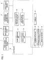
Fig. 1] Fig. 1 is a configuration diagram of a surrounding vehicle display device according to an embodiment of the present invention. - [
Fig. 2] Fig. 2 is a diagram for describing an example of a display region of a virtual image according to the embodiment of the present invention. - [
Fig. 3] Fig. 3 is a flowchart for describing an operation example of the surrounding vehicle display device according to the embodiment of the present invention. - [
Fig. 4] Fig. 4 is a diagram for describing another example of a display region of a virtual image according to an embodiment of the present invention. - Hereinafter, embodiments of the present invention are described with reference to the drawings. In the drawings, the same parts are indicated by the same reference signs and descriptions thereof are omitted.
- A configuration of a surrounding vehicle display device according to this embodiment is described with reference to
Fig. 1 . The surrounding vehicle display device includes a host vehiclelocation estimation device 1, amap obtainment device 2, a surroundinginformation detection device 3, avehicle speed sensor 4, acontroller 10,various actuators 6 to 8, and adisplay 9. Although the surrounding vehicle display device is described as a device used in an automated driving vehicle with an automated driving function in this embodiment, the surrounding vehicle display device may also be applied to a vehicle with no automated driving function. - The host vehicle
location estimation device 1 includes a location detection sensor for measuring an absolute location of the host vehicle such as a GPS (global positioning system) or an odometry mounted in the host vehicle. The host vehiclelocation estimation device 1 uses the location detection sensor to measure the absolute location of the host vehicle, that is, a location and orientation of the host vehicle with respect to a predetermined reference point. The host vehiclelocation estimation device 1 outputs the measured location information of the host vehicle to thecontroller 10. - The
map obtainment device 2 obtains map information indicating a configuration of a road where the host vehicle travels. The map information obtained by themap obtainment device 2 includes information on the road configuration such as absolute locations of traffic lanes and connection relationships and relative location relationships between the traffic lanes. Themap obtainment device 2 may have a map database storing the map information or may obtain the map information from an external map data server by cloud computing. Additionally, themap obtainment device 2 may obtain the map information through vehicle-to-vehicle communication and road-to-vehicle communication. Themap obtainment device 2 outputs the obtained map information to thecontroller 10. - The surrounding information detection device 3 (information sensor) includes multiple different types of object detection sensors mounted in the host vehicle. The object detection sensors are, for example, a laser range finder, laser radar, millimeter-wave radar, camera, and so on. The surrounding
information detection device 3 uses these object detection sensors to detect an object around the host vehicle. The surroundinginformation detection device 3 detects a moving object including another vehicle, a bike, a bicycle, and a pedestrian and a motionless object including a parking vehicle. For example, the surroundinginformation detection device 3 detects a location, orientation (yaw angle), size, speed, acceleration, jerk, deceleration, and yaw rate of the moving object and the motionless object with respect to the host vehicle. Additionally, the surroundinginformation detection device 3 detects a lane marking, traffic light, sign, and the like around the host vehicle. Moreover, the surroundinginformation detection device 3 may obtain the surrounding information through the vehicle-to-vehicle communication and the road-to-vehicle communication. The surroundinginformation detection device 3 outputs the detected information to thecontroller 10. - The
vehicle speed sensor 4 detects a vehicle speed of the host vehicle. Thevehicle speed sensor 4 outputs the detected vehicle speed of the host vehicle to thecontroller 10. - The
controller 10 obtains the information from the host vehiclelocation estimation device 1, themap obtainment device 2, the surroundinginformation detection device 3, and thevehicle speed sensor 4. Thecontroller 10 uses the obtained information to perform travelling control of the host vehicle automatically and generate a virtual image indicating another vehicle, a bike, a bicycle, a pedestrian, and the like around the host vehicle. - The
controller 10 is a general-purpose microcomputer including a CPU (central processing unit), memory, and input-output unit. The microcomputer is installed with a computer program for functioning the microcomputer as an automatic traveling control device and a surrounding vehicle display device. The microcomputer executes the computer program to function as multiple information processing circuits included in the automatic traveling control device and the surrounding vehicle display device. Note that, although there is shown an example of implementing the multiple information processing circuits included in the automatic traveling control device and the surrounding vehicle display device by software herein, needless to say, it is also possible to implement the information processing circuits by preparing dedicated hardware for executing the following information processing. Additionally, the multiple information processing circuits may be formed of individual pieces of hardware. - The
controller 10 includes aroute generation unit 11, avehicle control unit 12, a viewpointposition calculation unit 13, and a virtualimage generation unit 14 as the multiple information processing circuits. - The
route generation unit 11 generates a route to a destination that is set in advance by an occupant of the host vehicle. Theroute generation unit 11 outputs the generated route to thevehicle control unit 12. - The
vehicle control unit 12 controls asteering actuator 6, anaccelerator pedal actuator 7, abrake actuator 8, and the like using the information on the surroundings of the host vehicle to allow the host vehicle to automatically travel along the route obtained from theroute generation unit 11. - The viewpoint
position calculation unit 13 calculates a position and a direction of a virtual viewpoint. The virtual viewpoint is a viewpoint to look down the host vehicle from behind and above. Although the position of the virtual viewpoint is described as a position set on a central axis with respect to a vehicle-width direction of the host vehicle, the position of the virtual viewpoint is not limited thereto. The direction of the virtual viewpoint is an angle between a direction of a line of vision to look down the host vehicle from the position of the virtual viewpoint and a horizontal plane of the position of the virtual viewpoint. The viewpointposition calculation unit 13 outputs the calculated virtual viewpoint to the virtualimage generation unit 14. - The virtual
image generation unit 14 uses the information detected by the surroundinginformation detection device 3 and the like and the virtual viewpoint calculated by the viewpointposition calculation unit 13 to generate a virtual image so as to make an image of looking down from the virtual viewpoint. In other words, the virtualimage generation unit 14 generates a virtual image that indicates the surroundings of the host vehicle as being viewed from above the host vehicle. The virtualimage generation unit 14 outputs the generated virtual image to thedisplay 9. - The
display 9 is a device that is disposed close to a driver seat on an instrument panel to indicate to the occupant various kinds of information. Thedisplay 9 is, for example, formed of a liquid crystal panel and displays images of a speedometer, tachometer, and so on. Additionally, thedisplay 9 displays the virtual image generated by the virtualimage generation unit 14. Note that, thedisplay 9 may include a head-up display that uses a window glass of the host vehicle (for example, windshield) as a display screen. - Next, an operation example of the surrounding vehicle display device is described with reference to
Fig. 2 . - The viewpoint
position calculation unit 13 calculates the position and the direction of the virtual viewpoint according to the vehicle speed of ahost vehicle 20. As shown inFig. 2 , when thehost vehicle 20 is automatically traveling at a low speed, the viewpointposition calculation unit 13 calculates a position PI and the direction of the virtual viewpoint to make the virtual viewpoint relatively close to thehost vehicle 20. On the other hand, when thehost vehicle 20 is automatically traveling at a high speed, the viewpointposition calculation unit 13 calculates a position P2 and the direction of the virtual viewpoint to make the virtual viewpoint relatively far from thehost vehicle 20. - When the
host vehicle 20 is automatically traveling at a low speed, the virtualimage generation unit 14 generates avirtual image 30 so as to make an image of looking down from the position PI of the virtual viewpoint. As shown inFig. 2 , a display region of thevirtual image 30 includes aregion 20 m away from thehost vehicle 20 in a traveling direction and aregion 10 m away from thehost vehicle 20 in an opposite direction of the traveling direction. - Additionally, when the
host vehicle 20 is automatically traveling at a high speed, the virtualimage generation unit 14 generates avirtual image 31 so as to make an image of looking down from the position P2 of the virtual viewpoint. As shown inFig. 2 , a display region of thevirtual image 31 includes aregion 100 m away from thehost vehicle 20 in the traveling direction and aregion 70 m away from thehost vehicle 20 in the opposite direction of the traveling direction. - As shown by the
virtual image 30 and thevirtual image 31, when the vehicle speed of thehost vehicle 20 is higher than a low vehicle speed, the display region of thevirtual image 31 becomes wider than the display region of thevirtual image 30 in a front region and a rear region around thehost vehicle 20. - That is, when the vehicle speed of the
host vehicle 20 is higher than a low vehicle speed, the viewpointposition calculation unit 13 changes the position of the virtual viewpoint from the position PI to the position P2 to make the virtual viewpoint farther from thehost vehicle 20 and additionally changes the direction of the virtual viewpoint. - As described above, when the vehicle speed of the
host vehicle 20 is higher than a low vehicle speed, with the surrounding vehicle display device widening the display region of the virtual image, the occupant can grasp another vehicle, a bike, a bicycle, a pedestrian, and the like in a wide region around thehost vehicle 20. - The scenes where the vehicle speed of the
host vehicle 20 is a high speed may include a scene where thehost vehicle 20 performs traffic lane change, for example. When thehost vehicle 20 performs traffic lane change, it can be thought that the occupant wants to check another vehicle, a bike, a bicycle, a pedestrian, and the like in a wide area around thehost vehicle 20. Specifically, it can be thought that the occupant wants to check whether there is a following vehicle coming close from behind on a traffic lane next to the traffic lane where thehost vehicle 20 is traveling (a traffic lane to which thehost vehicle 20 moves). Thus, in this embodiment, when the vehicle speed of thehost vehicle 20 is higher than a low vehicle speed, the surrounding vehicle display device widens the display region of the virtual image of the front region and the rear region around thehost vehicle 20 and displays the widened display region of the virtual image on thedisplay 9. This allows the occupant to grasp another vehicle, a bike, a bicycle, a pedestrian, and the like behind thehost vehicle 20 in a wide area and feel safe about the automated driving. - Note that, although the viewpoint
position calculation unit 13 calculates both the position and direction of the virtual viewpoint in the operation example shown inFig. 2 , it is not limited thereto. It is sufficient that the viewpointposition calculation unit 13 calculates at least either of the position and the direction of the virtual viewpoint. For example, if the viewpointposition calculation unit 13 sets the position of the virtual viewpoint to a position far from thehost vehicle 20, the front region and the rear region around thehost vehicle 20 on the virtual image are widened. Additionally, the viewpointposition calculation unit 13 can set the direction of the virtual viewpoint so as to widen the front region and the rear region around thehost vehicle 20 on the virtual image. Moreover, the viewpointposition calculation unit 13 may change an angle of view and a focal length of the virtual viewpoint. That is, with the viewpointposition calculation unit 13 changing at least one of the features of the virtual viewpoint including the position, direction, angle of view, and focal length, the surrounding vehicle display device can widen the display region of the virtual image. - Next, an operation example of the surrounding vehicle display device is described with reference to a flowchart in
Fig. 3 . - In step S101, the
map obtainment device 2 and the surroundinginformation detection device 3 detect the information on the surroundings of thehost vehicle 20. For example, themap obtainment device 2 detects a configuration of the road where thehost vehicle 20 travels. The surroundinginformation detection device 3 detects another vehicle, a lane marking, and the like around thehost vehicle 20. Thereafter, the processing proceeds to step S102. - In step S102, the
vehicle speed sensor 4 detects the vehicle speed of thehost vehicle 20. Thereafter, the process proceeds to step S103. - In step S103, the viewpoint
position calculation unit 13 calculates the position and the direction of the virtual viewpoint according to the vehicle speed of thehost vehicle 20 detected in step S102. As shown inFig. 2 , when thehost vehicle 20 is automatically traveling at a low speed, the viewpointposition calculation unit 13 calculates the position PI and the direction of the virtual viewpoint to make the virtual viewpoint relatively close to thehost vehicle 20. On the other hand, when thehost vehicle 20 is automatically traveling at a high speed, the viewpointposition calculation unit 13 calculates the position P2 and the direction of the virtual viewpoint to make the virtual viewpoint relatively far from thehost vehicle 20. Thereafter, the process proceeds to step S104. - In step S104, the virtual
image generation unit 14 uses the information detected in step S101 and the position and the direction of the virtual viewpoint calculated in step S102 to generate thevirtual images display 9 displays thevirtual images - As described above, according to the surrounding vehicle display device of this embodiment, it is possible to achieve the following operations and effects.
- The surrounding vehicle display device obtains the information on the surroundings of the
host vehicle 20 and detects the vehicle speed of thehost vehicle 20. The virtualimage generation unit 14 uses the information on the surroundings of thehost vehicle 20 obtained by the surroundinginformation detection device 3 and the like and the virtual viewpoint calculated by the viewpointposition calculation unit 13 to generate the virtual image indicating the surroundings of thehost vehicle 20 being looked down from the above virtual viewpoint. When the detected vehicle speed is higher than a low vehicle speed, the surrounding vehicle display device widens the display region of the surroundings of thehost vehicle 20 on the virtual image and displays the virtual image on thedisplay 9. This allows the occupant to grasp another vehicle, a bike, a bicycle, a pedestrian, and the like in a wide region around thehost vehicle 20. - Additionally, the surrounding vehicle display device widens the display region of the virtual image of the front region and the rear region around the
host vehicle 20, that is, the display region of the virtual image in a front and rear direction of thehost vehicle 20. This allows the occupant to grasp another vehicle, a bike, a bicycle, a pedestrian, and the like in a wide region in the front region and the rear region around thehost vehicle 20. - Additionally, the surrounding vehicle display device widens the display region of the surroundings of the
host vehicle 20 on the virtual image by changing at least one of the features of the virtual viewpoint including the position, direction, angle of view, and focal length. This allows the occupant to grasp another vehicle, a bike, a bicycle, a pedestrian, and the like in a wide region around thehost vehicle 20. - The information on the surroundings of the
host vehicle 20 is information on the moving object including at least another vehicle, a bike, a bicycle, and a pedestrian and the motionless object at least including a parking vehicle. Since the information is what the occupant wants to know, the surrounding vehicle display device can meet the need of the occupant by displaying the information on the virtual image. - Additionally, the surrounding vehicle display device according to this embodiment is used in an automated driving vehicle that performs traveling control automatically. This allows the occupant to grasp another vehicle, a bike, a bicycle, a pedestrian, and the like in a wide region around the
host vehicle 20. Consequently, the occupant can feel safe about the automated driving. - Although the embodiment of the present invention is described above, the descriptions and the drawings as a part of the present disclosure should not be construed to limit the present invention. According to the present disclosure, various alternative embodiments, examples, and operational techniques will be apparent to those skilled in the art.
- For example, the surrounding vehicle display device may change at least either of the position and the direction of the virtual viewpoint to make the display region of the virtual image wider as the vehicle speed of the
host vehicle 20 becomes higher. With this linear widening of the display region of the virtual image according to the vehicle speed of thehost vehicle 20, the display region of the virtual image is gradually widened. That is, since the display region of the virtual image is not suddenly widened, the occupant can naturally grasp the change of the display region of the virtual image and can feel safe about the automated driving. - Additionally, the surrounding vehicle display device may change at least either of the position and the direction of the virtual viewpoint to widen the display region of the virtual image when the vehicle speed of the
host vehicle 20 becomes higher than a predetermined speed. This allows the occupant to easily grasp the change of the display region of the virtual image since the display region of the virtual image is changed based on the predetermined speed. Note that, the predetermined speed is stored in thecontroller 10 in advance. Only one speed or multiple different speeds may be stored as the predetermined speed. For example, the multiple and different predetermined speeds may be set as discrete speeds at every 10 km/h. Since this allows the display region of the virtual image to be gradually changed according to the speed, the occupant can easily grasp the change of the display region of the virtual image. - Additionally, the surrounding vehicle display device may make the display region of the virtual image wider as the predetermined speed stored in the
controller 10 is higher. That is, when the vehicle speed of thehost vehicle 20 becomes higher than the predetermined speed set to a high speed, the surrounding vehicle display device makes the display region of the virtual image wider than a case where the vehicle speed of thehost vehicle 20 becomes higher than the predetermined speed set to a low speed. This allows the occupant to easily grasp the change of the display region of the virtual image and also grasp another vehicle, a bike, a bicycle, a pedestrian, and the like in a wide region around thehost vehicle 20. - In this embodiment, as shown in
Fig. 2 , when thehost vehicle 20 is automatically traveling at a low speed, the display region of thevirtual image 30 includes theregion 20 m away from thehost vehicle 20 in the traveling direction and theregion 10 m away from thehost vehicle 20 in the opposite direction of the traveling direction. On the other hand, when thehost vehicle 20 is automatically traveling at a high speed, the display region of thevirtual image 31 includes theregion 100 m away from thehost vehicle 20 in the traveling direction and theregion 70 m away from thehost vehicle 20 in the opposite direction of the traveling direction. Although these distances are not limited, it is preferred to make an increase rate for widening the rear region around thehost vehicle 20 greater than an increase rate for widening the front region around thehost vehicle 20. For example, usingFig. 2 to give descriptions, the increase rate for widening the rear region around thehost vehicle 20 is seven times (from 10 m to 70 m), while the increase rate for widening the front region around thehost vehicle 20 is five times (from 20 m to 100 m). Like this, it is preferred to make the increase rate (seven times) for widening the rear region around thehost vehicle 20 greater than the increase rate (five times) for widening the front region around thehost vehicle 20. This makes it possible to satisfy the need of the occupant to check another vehicle, a bike, a bicycle, a pedestrian, and the like in the rear region around thehost vehicle 20. - Additionally, as shown in
Fig. 2 , when the vehicle speed of thehost vehicle 20 is a low speed, it is preferred to make the rear region around thehost vehicle 20 on the virtual image 30 (10 m) smaller than the front region around thehost vehicle 20 on the virtual image 30 (20 m). This is because, if the rear region around thehost vehicle 20 is wider when the vehicle speed of thehost vehicle 20 is a low speed, thehost vehicle 20 and another vehicle behind thehost vehicle 20 may be overlapped with each other on thevirtual image 30. When thehost vehicle 20 and the other vehicle overlap with each other like this case, it is impossible to recognize at a glance that which one of the overlapping vehicles is thehost vehicle 20. Otherwise, thehost vehicle 20 may be hidden by the other vehicle. For this reason, when the vehicle speed of thehost vehicle 20 is a low speed, the surrounding vehicle display device makes the rear region around thehost vehicle 20 on the virtual image smaller than the front region around thehost vehicle 20 on the virtual image. This allows the surrounding vehicle display device to prevent the overlapping of thehost vehicle 20 and the other vehicle on thevirtual image 30. Note that, a specific speed of the low speed may be set properly based on a traffic environment and may be stored as a second predetermined speed different from the abovementioned predetermined speed in thecontroller 10 in advance. - Although enlargement of the display region in the traveling direction of the
host vehicle 20 and the display region in the opposite direction of the traveling direction is described in this embodiment as shown inFig. 2 , it is not limited thereto. For example, in addition to the front and rear direction of thehost vehicle 20, the surrounding vehicle display device may widen the display region in the vehicle-width direction of the host vehicle. - Like a
virtual image 32 shown inFig. 4 , when the vehicle speed is higher than a low vehicle speed, the surrounding vehicle display device may widen the display region not only in the front and rear direction of the host vehicle but also in the vehicle-width direction of thehost vehicle 20. Comparing with thevirtual image 31 shown inFig. 2 , thevirtual image 32 displays another vehicle, a bike, and the like on three traffic lanes. This allows the occupant to grasp another vehicle, a bike, a bicycle, a pedestrian, and the like in a wide region around thehost vehicle 20 and feel safe about the automated driving. - Additionally, the surrounding vehicle display device may widen the front region and the rear region around the
host vehicle 20 on the virtual image when a vehicle speed of another vehicle traveling on the next traffic lane is higher than the vehicle speed of thehost vehicle 20. - Note that, display areas of the
virtual image 30 and thevirtual image 31 on thedisplay 9 may be either the same or different. For example, the surrounding vehicle display device may make the display area of thevirtual image 31 greater than the display area of thevirtual image 30 on thedisplay 9. With the surrounding vehicle display device increasing the display area of the virtual image on thedisplay 9 when the vehicle speed of thehost vehicle 20 is higher than a low vehicle speed, the occupant can grasp another vehicle, a bike, a bicycle, a pedestrian, and the like in a wide region around thehost vehicle 20 on a much larger virtual image. -
- 1
- host vehicle location estimation device
- 2
- map obtainment device
- 3
- surrounding information detection device
- 4
- vehicle speed sensor
- 9
- display
- 10
- controller
- 12
- vehicle control unit
- 13
- viewpoint position calculation unit
- 14
- virtual image generation unit
Claims (11)
- A surrounding vehicle display method, comprising:obtaining information on surroundings of a host vehicle;detecting a vehicle speed of the host vehicle;using the obtained information on the surroundings of the host vehicle to generate a virtual image that indicates the surroundings of the host vehicle as being viewed from above the host vehicle;making a display region of at least a rear region around the host vehicle on the virtual image wide when the detected vehicle speed is higher than a low vehicle speed; anddisplaying the virtual image on a display.
- The surrounding vehicle display method according to claim 1, wherein,
the display region of at least the rear region around the host vehicle on the virtual image is made wider as the vehicle speed becomes higher. - The surrounding vehicle display method according to claim 1, wherein,
the display region of at least the rear region around the host vehicle on the virtual image is made wider when the vehicle speed becomes higher than at least one predetermined speed. - The surrounding vehicle display method according to claim 3, wherein,
the display region of at least the rear region around the host vehicle on the virtual image is made wider as the predetermined speed is higher. - The surrounding vehicle display method according to any one of claims 1 to 4, wherein
a display region of a front region and the rear region around the host vehicle on the virtual image is made wide. - The surrounding vehicle display method according to claim 5, wherein
an increase rate for widening the rear region around the host vehicle on the virtual image is greater than an increase rate for widening the front region around the host vehicle on the virtual image. - The surrounding vehicle display method according to claim 5 or 6, wherein,
the rear region around the host vehicle on the virtual image is smaller than the front region around the host vehicle on the virtual image when the vehicle speed is lower than a second predetermined speed. - The surrounding vehicle display method according to any one of claims 1 to 7, wherein
a feature of an above virtual viewpoint is changed to make the display region of at least the rear region around the host vehicle on the virtual image wide. - The surrounding vehicle display method according to any one of claims 1 to 8, wherein
the information on the surroundings of the host vehicle is information on a moving object including at least another vehicle, a bike, a bicycle, and a pedestrian and a motionless object including at least a parking vehicle. - The surrounding vehicle display method according to any one of claims 1 to 9, wherein
the surrounding vehicle display method is used in an automated driving vehicle that performs travelling control of the host vehicle automatically. - A surrounding vehicle display device, comprising:an information sensor that obtains information on surroundings of a host vehicle;a vehicle speed sensor that detects a vehicle speed of the host vehicle;a controller that uses the information obtained by the information sensor to generate a virtual image that indicates the surroundings of the host vehicle as being viewed from above the host vehicle; anda display that displays the virtual image, whereinthe controller makes a display region of at least a rear region around the host vehicle on the virtual image wide when the detected vehicle speed is higher than a low vehicle speed.
Applications Claiming Priority (1)
| Application Number | Priority Date | Filing Date | Title |
|---|---|---|---|
| PCT/JP2017/030483 WO2019038904A1 (en) | 2017-08-25 | 2017-08-25 | Surrounding vehicle display method and surrounding vehicle display apparatus |
Publications (3)
| Publication Number | Publication Date |
|---|---|
| EP3675485A4 EP3675485A4 (en) | 2020-07-01 |
| EP3675485A1 true EP3675485A1 (en) | 2020-07-01 |
| EP3675485B1 EP3675485B1 (en) | 2021-03-24 |
Family
ID=65438451
Family Applications (1)
| Application Number | Title | Priority Date | Filing Date |
|---|---|---|---|
| EP17922800.2A Active EP3675485B1 (en) | 2017-08-25 | 2017-08-25 | Surrounding vehicle display method and surrounding vehicle display apparatus |
Country Status (5)
| Country | Link |
|---|---|
| US (1) | US11511667B2 (en) |
| EP (1) | EP3675485B1 (en) |
| JP (1) | JP6825710B2 (en) |
| CN (1) | CN111034186B (en) |
| WO (1) | WO2019038904A1 (en) |
Families Citing this family (6)
| Publication number | Priority date | Publication date | Assignee | Title |
|---|---|---|---|---|
| USD941321S1 (en) * | 2019-02-08 | 2022-01-18 | Nissan Motor Co., Ltd. | Display screen or portion thereof with graphical user interface |
| USD941322S1 (en) * | 2019-02-08 | 2022-01-18 | Nissan Motor Co., Ltd. | Display screen or portion thereof with graphical user interface |
| USD941323S1 (en) * | 2019-02-08 | 2022-01-18 | Nissan Motor Co., Ltd. | Display screen or portion thereof with graphical user interface |
| US11708024B2 (en) * | 2020-01-06 | 2023-07-25 | Gentex Corporation | Dynamic imaging system |
| JP2022048454A (en) * | 2020-09-15 | 2022-03-28 | マツダ株式会社 | Vehicle display device |
| JP7388329B2 (en) * | 2020-10-08 | 2023-11-29 | トヨタ自動車株式会社 | Vehicle display system and vehicle display method |
Family Cites Families (15)
| Publication number | Priority date | Publication date | Assignee | Title |
|---|---|---|---|---|
| EP1303140A4 (en) | 2000-07-19 | 2007-01-17 | Matsushita Electric Ind Co Ltd | Monitoring system |
| JP3372944B2 (en) * | 2000-07-19 | 2003-02-04 | 松下電器産業株式会社 | Monitoring system |
| JP2007094045A (en) * | 2005-09-29 | 2007-04-12 | Matsushita Electric Ind Co Ltd | Navigation apparatus, navigation method and vehicle |
| JP2009062020A (en) | 2007-09-10 | 2009-03-26 | Nissan Motor Co Ltd | Surrounding vehicle display device |
| JP2012195793A (en) * | 2011-03-17 | 2012-10-11 | Clarion Co Ltd | Vehicle periphery monitoring device |
| KR101265711B1 (en) * | 2011-11-30 | 2013-05-20 | 주식회사 이미지넥스트 | 3d vehicle around view generating method and apparatus |
| JP6310652B2 (en) * | 2013-07-03 | 2018-04-11 | クラリオン株式会社 | Video display system, video composition device, and video composition method |
| CN104512337B (en) * | 2013-10-04 | 2017-03-29 | 本田技研工业株式会社 | Display apparatus for displaying image of surroundings of vehicle |
| CN203611863U (en) * | 2013-12-03 | 2014-05-28 | 长安大学 | Vehicle safety pre-warning system based on automatic image splicing |
| JP6307895B2 (en) | 2014-01-23 | 2018-04-11 | トヨタ自動車株式会社 | Vehicle periphery monitoring device |
| KR102375411B1 (en) * | 2015-05-11 | 2022-03-18 | 삼성전자주식회사 | Method and apparatus for providing around view of vehicle |
| CN108141569B (en) * | 2015-10-08 | 2020-04-28 | 日产自动车株式会社 | Display support device and display support method |
| CN205098053U (en) * | 2015-11-13 | 2016-03-23 | 福建捷联电子有限公司 | Can improve intelligent display device behind driving safety's car |
| JP6665605B2 (en) | 2016-03-15 | 2020-03-13 | 株式会社デンソー | Display control device and display control method |
| CN110786004B (en) * | 2017-08-25 | 2021-08-31 | 本田技研工业株式会社 | Display control device, display control method, and storage medium |
-
2017
- 2017-08-25 EP EP17922800.2A patent/EP3675485B1/en active Active
- 2017-08-25 US US16/641,912 patent/US11511667B2/en active Active
- 2017-08-25 CN CN201780094263.5A patent/CN111034186B/en active Active
- 2017-08-25 WO PCT/JP2017/030483 patent/WO2019038904A1/en unknown
- 2017-08-25 JP JP2019537520A patent/JP6825710B2/en active Active
Also Published As
| Publication number | Publication date |
|---|---|
| US11511667B2 (en) | 2022-11-29 |
| CN111034186A (en) | 2020-04-17 |
| JP6825710B2 (en) | 2021-02-03 |
| CN111034186B (en) | 2021-04-02 |
| EP3675485A4 (en) | 2020-07-01 |
| EP3675485B1 (en) | 2021-03-24 |
| US20200247319A1 (en) | 2020-08-06 |
| JPWO2019038904A1 (en) | 2020-11-19 |
| WO2019038904A1 (en) | 2019-02-28 |
Similar Documents
| Publication | Publication Date | Title |
|---|---|---|
| EP3675484B1 (en) | Surrounding vehicle display method and surrounding vehicle display apparatus | |
| EP3675485B1 (en) | Surrounding vehicle display method and surrounding vehicle display apparatus | |
| US10710502B2 (en) | In-vehicle alert apparatus and alert method | |
| US9827907B2 (en) | Drive assist device | |
| US10589673B2 (en) | In-vehicle alert device | |
| US9074906B2 (en) | Road shape recognition device | |
| US9460626B2 (en) | Driving support device and driving support method | |
| WO2020125178A1 (en) | Vehicle driving prompting method and apparatus | |
| CN111788459A (en) | Presentation of auxiliary information on a display unit | |
| JP2012519346A (en) | Method for automatically recognizing driving maneuvering of a vehicle and driver assistance system including the method | |
| JP7047824B2 (en) | Vehicle control unit | |
| JP2008242544A (en) | Collision avoidance device and method | |
| JP6969509B2 (en) | Vehicle display control device, vehicle display control method, and control program | |
| JP2022041244A (en) | On-vehicle display device, method, and program | |
| JP7400242B2 (en) | Vehicle display control device and vehicle display control method | |
| KR20210004317A (en) | Control apparatus for collision prevention of vehicle and method thereof | |
| US20240106989A1 (en) | Vehicle display control device and non-transitory computer-readable medium | |
| WO2020246114A1 (en) | Display control device and display control program | |
| JP2022041286A (en) | Display control device, display control method, and display control program | |
| JP2023010340A (en) | Driving assistance method, driving assistance device and communication system | |
| GB2609482A (en) | Method and system for creating a virtual lane for a vehicle | |
| JP2023039693A (en) | Display control device, display control program and virtual image display system | |
| JP2021028587A (en) | In-vehicle display control device |
Legal Events
| Date | Code | Title | Description |
|---|---|---|---|
| STAA | Information on the status of an ep patent application or granted ep patent |
Free format text: STATUS: THE INTERNATIONAL PUBLICATION HAS BEEN MADE |
|
| PUAI | Public reference made under article 153(3) epc to a published international application that has entered the european phase |
Free format text: ORIGINAL CODE: 0009012 |
|
| STAA | Information on the status of an ep patent application or granted ep patent |
Free format text: STATUS: REQUEST FOR EXAMINATION WAS MADE |
|
| 17P | Request for examination filed |
Effective date: 20200323 |
|
| A4 | Supplementary search report drawn up and despatched |
Effective date: 20200428 |
|
| AK | Designated contracting states |
Kind code of ref document: A1 Designated state(s): AL AT BE BG CH CY CZ DE DK EE ES FI FR GB GR HR HU IE IS IT LI LT LU LV MC MK MT NL NO PL PT RO RS SE SI SK SM TR |
|
| AX | Request for extension of the european patent |
Extension state: BA ME |
|
| DAV | Request for validation of the european patent (deleted) | ||
| DAX | Request for extension of the european patent (deleted) | ||
| GRAP | Despatch of communication of intention to grant a patent |
Free format text: ORIGINAL CODE: EPIDOSNIGR1 |
|
| STAA | Information on the status of an ep patent application or granted ep patent |
Free format text: STATUS: GRANT OF PATENT IS INTENDED |
|
| INTG | Intention to grant announced |
Effective date: 20201221 |
|
| GRAS | Grant fee paid |
Free format text: ORIGINAL CODE: EPIDOSNIGR3 |
|
| GRAA | (expected) grant |
Free format text: ORIGINAL CODE: 0009210 |
|
| STAA | Information on the status of an ep patent application or granted ep patent |
Free format text: STATUS: THE PATENT HAS BEEN GRANTED |
|
| AK | Designated contracting states |
Kind code of ref document: B1 Designated state(s): AL AT BE BG CH CY CZ DE DK EE ES FI FR GB GR HR HU IE IS IT LI LT LU LV MC MK MT NL NO PL PT RO RS SE SI SK SM TR |
|
| REG | Reference to a national code |
Ref country code: GB Ref legal event code: FG4D |
|
| REG | Reference to a national code |
Ref country code: CH Ref legal event code: EP |
|
| REG | Reference to a national code |
Ref country code: IE Ref legal event code: FG4D |
|
| REG | Reference to a national code |
Ref country code: AT Ref legal event code: REF Ref document number: 1375700 Country of ref document: AT Kind code of ref document: T Effective date: 20210415 Ref country code: DE Ref legal event code: R096 Ref document number: 602017035493 Country of ref document: DE |
|
| REG | Reference to a national code |
Ref country code: LT Ref legal event code: MG9D |
|
| PG25 | Lapsed in a contracting state [announced via postgrant information from national office to epo] |
Ref country code: FI Free format text: LAPSE BECAUSE OF FAILURE TO SUBMIT A TRANSLATION OF THE DESCRIPTION OR TO PAY THE FEE WITHIN THE PRESCRIBED TIME-LIMIT Effective date: 20210324 Ref country code: HR Free format text: LAPSE BECAUSE OF FAILURE TO SUBMIT A TRANSLATION OF THE DESCRIPTION OR TO PAY THE FEE WITHIN THE PRESCRIBED TIME-LIMIT Effective date: 20210324 Ref country code: GR Free format text: LAPSE BECAUSE OF FAILURE TO SUBMIT A TRANSLATION OF THE DESCRIPTION OR TO PAY THE FEE WITHIN THE PRESCRIBED TIME-LIMIT Effective date: 20210625 Ref country code: NO Free format text: LAPSE BECAUSE OF FAILURE TO SUBMIT A TRANSLATION OF THE DESCRIPTION OR TO PAY THE FEE WITHIN THE PRESCRIBED TIME-LIMIT Effective date: 20210624 Ref country code: BG Free format text: LAPSE BECAUSE OF FAILURE TO SUBMIT A TRANSLATION OF THE DESCRIPTION OR TO PAY THE FEE WITHIN THE PRESCRIBED TIME-LIMIT Effective date: 20210624 |
|
| PG25 | Lapsed in a contracting state [announced via postgrant information from national office to epo] |
Ref country code: RS Free format text: LAPSE BECAUSE OF FAILURE TO SUBMIT A TRANSLATION OF THE DESCRIPTION OR TO PAY THE FEE WITHIN THE PRESCRIBED TIME-LIMIT Effective date: 20210324 Ref country code: LV Free format text: LAPSE BECAUSE OF FAILURE TO SUBMIT A TRANSLATION OF THE DESCRIPTION OR TO PAY THE FEE WITHIN THE PRESCRIBED TIME-LIMIT Effective date: 20210324 Ref country code: SE Free format text: LAPSE BECAUSE OF FAILURE TO SUBMIT A TRANSLATION OF THE DESCRIPTION OR TO PAY THE FEE WITHIN THE PRESCRIBED TIME-LIMIT Effective date: 20210324 |
|
| REG | Reference to a national code |
Ref country code: NL Ref legal event code: MP Effective date: 20210324 |
|
| REG | Reference to a national code |
Ref country code: AT Ref legal event code: MK05 Ref document number: 1375700 Country of ref document: AT Kind code of ref document: T Effective date: 20210324 |
|
| PG25 | Lapsed in a contracting state [announced via postgrant information from national office to epo] |
Ref country code: NL Free format text: LAPSE BECAUSE OF FAILURE TO SUBMIT A TRANSLATION OF THE DESCRIPTION OR TO PAY THE FEE WITHIN THE PRESCRIBED TIME-LIMIT Effective date: 20210324 |
|
| PG25 | Lapsed in a contracting state [announced via postgrant information from national office to epo] |
Ref country code: AT Free format text: LAPSE BECAUSE OF FAILURE TO SUBMIT A TRANSLATION OF THE DESCRIPTION OR TO PAY THE FEE WITHIN THE PRESCRIBED TIME-LIMIT Effective date: 20210324 Ref country code: SM Free format text: LAPSE BECAUSE OF FAILURE TO SUBMIT A TRANSLATION OF THE DESCRIPTION OR TO PAY THE FEE WITHIN THE PRESCRIBED TIME-LIMIT Effective date: 20210324 Ref country code: CZ Free format text: LAPSE BECAUSE OF FAILURE TO SUBMIT A TRANSLATION OF THE DESCRIPTION OR TO PAY THE FEE WITHIN THE PRESCRIBED TIME-LIMIT Effective date: 20210324 Ref country code: EE Free format text: LAPSE BECAUSE OF FAILURE TO SUBMIT A TRANSLATION OF THE DESCRIPTION OR TO PAY THE FEE WITHIN THE PRESCRIBED TIME-LIMIT Effective date: 20210324 Ref country code: LT Free format text: LAPSE BECAUSE OF FAILURE TO SUBMIT A TRANSLATION OF THE DESCRIPTION OR TO PAY THE FEE WITHIN THE PRESCRIBED TIME-LIMIT Effective date: 20210324 |
|
| PG25 | Lapsed in a contracting state [announced via postgrant information from national office to epo] |
Ref country code: RO Free format text: LAPSE BECAUSE OF FAILURE TO SUBMIT A TRANSLATION OF THE DESCRIPTION OR TO PAY THE FEE WITHIN THE PRESCRIBED TIME-LIMIT Effective date: 20210324 Ref country code: SK Free format text: LAPSE BECAUSE OF FAILURE TO SUBMIT A TRANSLATION OF THE DESCRIPTION OR TO PAY THE FEE WITHIN THE PRESCRIBED TIME-LIMIT Effective date: 20210324 Ref country code: PL Free format text: LAPSE BECAUSE OF FAILURE TO SUBMIT A TRANSLATION OF THE DESCRIPTION OR TO PAY THE FEE WITHIN THE PRESCRIBED TIME-LIMIT Effective date: 20210324 Ref country code: PT Free format text: LAPSE BECAUSE OF FAILURE TO SUBMIT A TRANSLATION OF THE DESCRIPTION OR TO PAY THE FEE WITHIN THE PRESCRIBED TIME-LIMIT Effective date: 20210726 Ref country code: IS Free format text: LAPSE BECAUSE OF FAILURE TO SUBMIT A TRANSLATION OF THE DESCRIPTION OR TO PAY THE FEE WITHIN THE PRESCRIBED TIME-LIMIT Effective date: 20210724 |
|
| REG | Reference to a national code |
Ref country code: DE Ref legal event code: R097 Ref document number: 602017035493 Country of ref document: DE |
|
| PG25 | Lapsed in a contracting state [announced via postgrant information from national office to epo] |
Ref country code: ES Free format text: LAPSE BECAUSE OF FAILURE TO SUBMIT A TRANSLATION OF THE DESCRIPTION OR TO PAY THE FEE WITHIN THE PRESCRIBED TIME-LIMIT Effective date: 20210324 Ref country code: DK Free format text: LAPSE BECAUSE OF FAILURE TO SUBMIT A TRANSLATION OF THE DESCRIPTION OR TO PAY THE FEE WITHIN THE PRESCRIBED TIME-LIMIT Effective date: 20210324 Ref country code: AL Free format text: LAPSE BECAUSE OF FAILURE TO SUBMIT A TRANSLATION OF THE DESCRIPTION OR TO PAY THE FEE WITHIN THE PRESCRIBED TIME-LIMIT Effective date: 20210324 |
|
| PLBE | No opposition filed within time limit |
Free format text: ORIGINAL CODE: 0009261 |
|
| STAA | Information on the status of an ep patent application or granted ep patent |
Free format text: STATUS: NO OPPOSITION FILED WITHIN TIME LIMIT |
|
| RAP4 | Party data changed (patent owner data changed or rights of a patent transferred) |
Owner name: RENAULT S.A.S Owner name: NISSAN MOTOR CO., LTD. |
|
| 26N | No opposition filed |
Effective date: 20220104 |
|
| REG | Reference to a national code |
Ref country code: CH Ref legal event code: PL |
|
| PG25 | Lapsed in a contracting state [announced via postgrant information from national office to epo] |
Ref country code: MC Free format text: LAPSE BECAUSE OF FAILURE TO SUBMIT A TRANSLATION OF THE DESCRIPTION OR TO PAY THE FEE WITHIN THE PRESCRIBED TIME-LIMIT Effective date: 20210324 |
|
| REG | Reference to a national code |
Ref country code: BE Ref legal event code: MM Effective date: 20210831 |
|
| PG25 | Lapsed in a contracting state [announced via postgrant information from national office to epo] |
Ref country code: LI Free format text: LAPSE BECAUSE OF NON-PAYMENT OF DUE FEES Effective date: 20210831 Ref country code: CH Free format text: LAPSE BECAUSE OF NON-PAYMENT OF DUE FEES Effective date: 20210831 |
|
| PG25 | Lapsed in a contracting state [announced via postgrant information from national office to epo] |
Ref country code: IS Free format text: LAPSE BECAUSE OF FAILURE TO SUBMIT A TRANSLATION OF THE DESCRIPTION OR TO PAY THE FEE WITHIN THE PRESCRIBED TIME-LIMIT Effective date: 20210724 Ref country code: LU Free format text: LAPSE BECAUSE OF NON-PAYMENT OF DUE FEES Effective date: 20210825 |
|
| PG25 | Lapsed in a contracting state [announced via postgrant information from national office to epo] |
Ref country code: IE Free format text: LAPSE BECAUSE OF NON-PAYMENT OF DUE FEES Effective date: 20210825 Ref country code: BE Free format text: LAPSE BECAUSE OF NON-PAYMENT OF DUE FEES Effective date: 20210831 |
|
| PG25 | Lapsed in a contracting state [announced via postgrant information from national office to epo] |
Ref country code: IT Free format text: LAPSE BECAUSE OF FAILURE TO SUBMIT A TRANSLATION OF THE DESCRIPTION OR TO PAY THE FEE WITHIN THE PRESCRIBED TIME-LIMIT Effective date: 20210324 |
|
| PG25 | Lapsed in a contracting state [announced via postgrant information from national office to epo] |
Ref country code: CY Free format text: LAPSE BECAUSE OF FAILURE TO SUBMIT A TRANSLATION OF THE DESCRIPTION OR TO PAY THE FEE WITHIN THE PRESCRIBED TIME-LIMIT Effective date: 20210324 |
|
| PG25 | Lapsed in a contracting state [announced via postgrant information from national office to epo] |
Ref country code: HU Free format text: LAPSE BECAUSE OF FAILURE TO SUBMIT A TRANSLATION OF THE DESCRIPTION OR TO PAY THE FEE WITHIN THE PRESCRIBED TIME-LIMIT; INVALID AB INITIO Effective date: 20170825 |
|
| PG25 | Lapsed in a contracting state [announced via postgrant information from national office to epo] |
Ref country code: SI Free format text: LAPSE BECAUSE OF FAILURE TO SUBMIT A TRANSLATION OF THE DESCRIPTION OR TO PAY THE FEE WITHIN THE PRESCRIBED TIME-LIMIT Effective date: 20210324 |
|
| PGFP | Annual fee paid to national office [announced via postgrant information from national office to epo] |
Ref country code: GB Payment date: 20230720 Year of fee payment: 7 |
|
| PGFP | Annual fee paid to national office [announced via postgrant information from national office to epo] |
Ref country code: FR Payment date: 20230720 Year of fee payment: 7 Ref country code: DE Payment date: 20230720 Year of fee payment: 7 |
|
| PG25 | Lapsed in a contracting state [announced via postgrant information from national office to epo] |
Ref country code: MK Free format text: LAPSE BECAUSE OF FAILURE TO SUBMIT A TRANSLATION OF THE DESCRIPTION OR TO PAY THE FEE WITHIN THE PRESCRIBED TIME-LIMIT Effective date: 20210324 |