EP3675349A1 - Electric pump - Google Patents
Electric pump Download PDFInfo
- Publication number
- EP3675349A1 EP3675349A1 EP19219642.6A EP19219642A EP3675349A1 EP 3675349 A1 EP3675349 A1 EP 3675349A1 EP 19219642 A EP19219642 A EP 19219642A EP 3675349 A1 EP3675349 A1 EP 3675349A1
- Authority
- EP
- European Patent Office
- Prior art keywords
- motor
- current
- control
- mode
- restriction
- Prior art date
- Legal status (The legal status is an assumption and is not a legal conclusion. Google has not performed a legal analysis and makes no representation as to the accuracy of the status listed.)
- Granted
Links
Images



Classifications
-
- F—MECHANICAL ENGINEERING; LIGHTING; HEATING; WEAPONS; BLASTING
- F04—POSITIVE - DISPLACEMENT MACHINES FOR LIQUIDS; PUMPS FOR LIQUIDS OR ELASTIC FLUIDS
- F04B—POSITIVE-DISPLACEMENT MACHINES FOR LIQUIDS; PUMPS
- F04B49/00—Control, e.g. of pump delivery, or pump pressure of, or safety measures for, machines, pumps, or pumping installations, not otherwise provided for, or of interest apart from, groups F04B1/00 - F04B47/00
- F04B49/06—Control using electricity
-
- F—MECHANICAL ENGINEERING; LIGHTING; HEATING; WEAPONS; BLASTING
- F04—POSITIVE - DISPLACEMENT MACHINES FOR LIQUIDS; PUMPS FOR LIQUIDS OR ELASTIC FLUIDS
- F04B—POSITIVE-DISPLACEMENT MACHINES FOR LIQUIDS; PUMPS
- F04B17/00—Pumps characterised by combination with, or adaptation to, specific driving engines or motors
- F04B17/03—Pumps characterised by combination with, or adaptation to, specific driving engines or motors driven by electric motors
-
- F—MECHANICAL ENGINEERING; LIGHTING; HEATING; WEAPONS; BLASTING
- F04—POSITIVE - DISPLACEMENT MACHINES FOR LIQUIDS; PUMPS FOR LIQUIDS OR ELASTIC FLUIDS
- F04B—POSITIVE-DISPLACEMENT MACHINES FOR LIQUIDS; PUMPS
- F04B49/00—Control, e.g. of pump delivery, or pump pressure of, or safety measures for, machines, pumps, or pumping installations, not otherwise provided for, or of interest apart from, groups F04B1/00 - F04B47/00
- F04B49/06—Control using electricity
- F04B49/065—Control using electricity and making use of computers
-
- H—ELECTRICITY
- H02—GENERATION; CONVERSION OR DISTRIBUTION OF ELECTRIC POWER
- H02P—CONTROL OR REGULATION OF ELECTRIC MOTORS, ELECTRIC GENERATORS OR DYNAMO-ELECTRIC CONVERTERS; CONTROLLING TRANSFORMERS, REACTORS OR CHOKE COILS
- H02P6/00—Arrangements for controlling synchronous motors or other dynamo-electric motors using electronic commutation dependent on the rotor position; Electronic commutators therefor
- H02P6/28—Arrangements for controlling current
-
- H—ELECTRICITY
- H02—GENERATION; CONVERSION OR DISTRIBUTION OF ELECTRIC POWER
- H02P—CONTROL OR REGULATION OF ELECTRIC MOTORS, ELECTRIC GENERATORS OR DYNAMO-ELECTRIC CONVERTERS; CONTROLLING TRANSFORMERS, REACTORS OR CHOKE COILS
- H02P7/00—Arrangements for regulating or controlling the speed or torque of electric DC motors
- H02P7/06—Arrangements for regulating or controlling the speed or torque of electric DC motors for regulating or controlling an individual DC dynamo-electric motor by varying field or armature current
- H02P7/08—Arrangements for regulating or controlling the speed or torque of electric DC motors for regulating or controlling an individual DC dynamo-electric motor by varying field or armature current by manual control without auxiliary power
-
- F—MECHANICAL ENGINEERING; LIGHTING; HEATING; WEAPONS; BLASTING
- F04—POSITIVE - DISPLACEMENT MACHINES FOR LIQUIDS; PUMPS FOR LIQUIDS OR ELASTIC FLUIDS
- F04B—POSITIVE-DISPLACEMENT MACHINES FOR LIQUIDS; PUMPS
- F04B2203/00—Motor parameters
- F04B2203/02—Motor parameters of rotating electric motors
- F04B2203/0201—Current
-
- F—MECHANICAL ENGINEERING; LIGHTING; HEATING; WEAPONS; BLASTING
- F04—POSITIVE - DISPLACEMENT MACHINES FOR LIQUIDS; PUMPS FOR LIQUIDS OR ELASTIC FLUIDS
- F04B—POSITIVE-DISPLACEMENT MACHINES FOR LIQUIDS; PUMPS
- F04B2203/00—Motor parameters
- F04B2203/02—Motor parameters of rotating electric motors
- F04B2203/0202—Voltage
-
- F—MECHANICAL ENGINEERING; LIGHTING; HEATING; WEAPONS; BLASTING
- F04—POSITIVE - DISPLACEMENT MACHINES FOR LIQUIDS; PUMPS FOR LIQUIDS OR ELASTIC FLUIDS
- F04B—POSITIVE-DISPLACEMENT MACHINES FOR LIQUIDS; PUMPS
- F04B2203/00—Motor parameters
- F04B2203/04—Motor parameters of linear electric motors
- F04B2203/0401—Current
-
- F—MECHANICAL ENGINEERING; LIGHTING; HEATING; WEAPONS; BLASTING
- F04—POSITIVE - DISPLACEMENT MACHINES FOR LIQUIDS; PUMPS FOR LIQUIDS OR ELASTIC FLUIDS
- F04B—POSITIVE-DISPLACEMENT MACHINES FOR LIQUIDS; PUMPS
- F04B2203/00—Motor parameters
- F04B2203/04—Motor parameters of linear electric motors
- F04B2203/0402—Voltage
Definitions
- the invention relates to an electric pump.
- JP 2015-175290 A discloses an electric pump including a controller capable of switching a motor between constant current control and constant voltage control.
- JP 2004-166436 A discloses a control device that controls a brushless direct-current (DC) motor by any one of current feedback control and rotation speed control.
- the constant voltage control disclosed in JP 2015-175290 A performs control such that a voltage value of power supplied to the motor is kept constant. As a result, when the load increases, the current value supplied to the motor increases, and in some cases, may exceed the current value that can be allowed by a system including the motor.
- the invention is to provide an electric pump capable of suppressing inconvenience of supplying an excessive current in a situation where a load of a motor increases, without sacrificing the effectiveness of voltage control.
- An aspect of the invention relates to an electric pump.
- the electric pump includes a pump unit, a motor, and a controller.
- the pump unit is configured to pump fluid by a rotating operation.
- the motor is a brushless direct-current (DC) motor and is configured to rotationally drive the pump unit.
- the controller is configured to control a current to be supplied to the motor.
- the controller is configured to switch between voltage control for controlling the current to be supplied to the motor based on a target voltage and current control for controlling the current to be supplied to the motor based on a target current.
- the electric pump it is possible to easily control the rotation speed (the number of revolutions per unit time) of the brushless DC motor by the voltage control, for example, by converting the current from the power source into a target voltage by pulse-width modulation (PWM) and supplying the converted target voltage to the brushless DC motor.
- PWM pulse-width modulation
- the load acting on the pump unit increases, it is possible to suppress inconvenience of supplying an excessive current to the motor by controlling the current to be supplied to the motor by the current control. Therefore, it is possible to suppress the supply of an excessive current in a situation where a load of a motor increases, without sacrificing the effectiveness of voltage control.
- the controller may be configured to select, as an operation mode, one of a restriction possible mode for performing control by switching between the voltage control and the current control and a non-restriction mode for performing only the voltage control.
- the electric pump when determination is made to select the restriction possible mode as the operation mode, it is possible to suppress supply of the excessive current to the motor, for example, by switching the control to the current control when the load acting on the motor increases.
- the non-restriction mode as the operation mode, it is possible to continuously supply current to the motor, for example, even in a situation where the load acting on the motor varies somewhat. In this way, it is possible to suppress great reduction in the discharge amount of the fluid in the pump unit and step-out of the motor.
- the controller may set an upper limit current value to be supplied to the motor to a limit value in the restriction possible mode.
- the controller may be configured to, in the restriction possible mode, perform the voltage control in a situation where the current to be supplied to the motor is less than the limit value.
- the controller may be configured to, in the restriction possible mode, supply the current less than the limit value to the motor by the current control, instead of the voltage control, in a situation where the current to be supplied to the motor is equal to or greater than the limit value.
- the setting of the limit value in advance makes it possible to perform the voltage control when the current to be supplied to the motor is less than the limit value, and to supply the current less than the limit value by the current control, instead of the voltage control, in the situation where the current to be supplied to the motor is equal to or greater than the limit value. That is, just by setting the upper limit current value supplied to the motor to the limit value, switching from the voltage control to the current control can be automatically performed, and in the current control, the current exceeding the limit value is not supplied to the motor.
- the controller may be configured to select the non-restriction mode when a rotation speed of the motor per unit time is less than a first set value.
- the controller may be configured to select the restriction possible mode when the rotation speed is equal to or greater than the first set value.
- the controller selects the non-restriction mode as the operation mode when the rotation speed of the motor per unit time is less than the first set value. For this reason, it is possible to supply a sufficient current and to suppress the speed reduction and suppress the step-out with regard to the motor, even when the motor rotates at a low speed.
- the operation mode is determined to be the restriction possible mode when the rotation speed of the motor per unit time is equal to or greater than the first set value. For this reason, for example, when the current to be supplied to the motor rises to the limit value during performing the voltage control, it is possible to suppress the supply of the excessive current exceeding the limit value to the motor by switching to the current control.
- the operation mode shifts to the non-restriction mode when the rotation speed falls below the first set value during performing control in the restriction possible mode. In this way, it is possible to supply the current exceeding the limit value, and thus to suppress the step-out of the motor.
- the controller may be is configured to select the restriction possible mode when a rotation speed of the motor per unit time is equal to or greater than a second set value in a situation that the operation mode is the non-restriction mode.
- the controller may be configured to select the non-restriction mode when the rotation speed falls below a third set value that is smaller than the second set value in a situation that the operation mode is the restriction possible mode.
- the operation mode shifts to the restriction possible mode when the rotation speed of the motor per unit time is equal to or greater than the second set value in a situation of the non-restriction mode. In this way, it is possible to appropriately perform the switching between the non-restriction mode and the restriction possible mode.
- an electric pump P is configured to include a pump unit 1 that pumps fluid by rotating operation, a brushless direct-current (DC) motor 2 that rotationally drives the pump unit 1, and a controller 10 that controls current to be supplied to the motor 2.
- DC direct-current
- the electric pump P may be used, for example, for supplying oil stored in a transmission case or the like in a traveling drive system of a vehicle.
- the electric pump P supplies current supplied from a DC power source 3 formed of a battery provided in the vehicle to the motor 2 through a controller 10.
- the fluid supplied by the electric pump P is not limited to oil, and may be a liquid such as coolant.
- the motor 2 includes field coils, which is common to a three-phase motor in configuration, and a rotor (not shown) having a permanent magnet that is rotated by the magnetic force acting from the field coils, and the pump unit 1 is driven by a driving force of the rotor.
- the motor 2 is a sensorless-type motor that does not have a sensor for detecting a rotational position of the rotor.
- the controller 10 includes a driver unit 11, a current control unit 12, a rotational position detection unit 13 and a control management unit 14.
- the driver unit 11 has a plurality of field effect transistors (FETs) which is controlled to be in an ON state when a current is supplied to the motor 2.
- the current control unit 12 has a driving circuit that generates a control signal with a target duty ratio corresponding to a target driving voltage by a pulse-width modulation (PWM) technology and individually drives the FETs of the driver unit 11 at the timing synchronized with a detection signal of the rotational position detection unit 13.
- PWM pulse-width modulation
- the current control unit 12 is configured to perform vector control.
- the rotational position detection unit 13 the rotational position of the rotor from the induction voltage generated by each of coils of the motor 2 when the rotor rotates.
- the control management unit 14 is configured to set an upper limit value Dmax and a lower limit value Dmin of the FET driving duty ratio by PWM, based on temperature information of the transmission case, target information, the power supply voltage, the power supply current, and the like, and to allow the control of the motor 2 to be switched between the voltage control and the current control.
- the temperature information of the transmission case is sensed by a temperature sensor 4, and the target information includes a target amount of oil to be supplied.
- the driver unit 11, the current control unit 12 and the rotational position detection unit 13 are implemented by hardware, and the control management unit 14 is implemented by a combination of hardware and software.
- control management unit 14 performs a control on the pump unit 1 (hereinafter referred to as 'pump control').
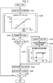
- control information is acquired, and FET driving Duty is calculated (steps S101 and S102).
- control information is a target oil discharge amount of oil per unit time, temperature information acquired by the temperature sensor 4, or the like.
- control information is a target oil discharge amount of oil per unit time, temperature information acquired by the temperature sensor 4, or the like.
- step S102 a graph is illustrated in which a value of the FET driving duty ratio Dsig is acquired from a predetermined characteristic line L based on an input signal as the control information, where a horizontal axis represents the input value (the unit is duty ratio (%)) and a vertical axis represents the FET driving Duty (the unit is duty ratio (%)).
- the FET driving Duty is a driving signal with the duty ratio of PWM when the field coils of the motor 2 are actually driven by the current control unit 12 driving the FETs of the driver unit 11.
- step S104 it is necessary that the rotor of the motor 2 is in a rotating state to detect the rotation of the rotor in step S104.
- step S105 the rotation speed per unit time is calculated, and in step S106, the approximate rotation speed is calculated.
- the approximate rotation speed is assumed to be a value that may not be affected by variation in the rotation speed acquired in real time. For example, a value of the average rotation speed within a set time, the moving average, a value obtained by rounding off a numerical value of a predetermined digit, or the average value of the rotation speed of the rotor acquired at a predetermined interval.
- step S 107 for example, in a situation where the approximate rotation speed is less than 800 rpm as a second set value, such as immediately after the rotor of the motor 2 starts rotating from a standstill state or when the rotor continues to rotate at a low rotation speed, the non-restriction mode Ma is selected and determined as the operation mode.
- the restriction possible mode Mb is selected and determined as the operation mode.
- the non-restriction mode Ma is a mode in which the upper limit of the FET driving Duty can be set to 100% and voltage control is performed.
- the restriction possible mode Mb is a mode in which the upper limit of the FET driving Duty is set to be less than 100%, voltage control is performed until the FET driving Duty reaches the upper limit, and the FET driving Duty is maintained at the upper limit by current control when the FET driving Duty is equal to or greater than the upper limit.
- the restriction possible mode Mb is maintained, for example, until the approximate rotation speed falls below 500 rpm as a third set value.
- the non-restriction mode Ma is selected as the operation mode, and the non-restriction mode Ma is maintained until the approximate rotation speed reaches 800 rpm or more.
- 500 rpm (third set value) and 800 rpm (second set value) are values set when the specific electric pump P is controlled, and any values can be set as the rotation speed for determining the operation mode.
- the switching between the non-restriction mode Ma and the restriction possible mode Mb may be performed all at 500 rpm (first set value).
- step S104 when rotation of the rotor is not detected in step S104, and after the processing of determining the mode in step S107 has been performed, information on the driver unit 11 is acquired (step S 108), a motor control routine is executed (step S200), and then processes from step 101 are repeated unless the entire control is reset.
- the motor control routine (step S200) is set as a subroutine, and a control process thereof is shown as a flowchart in FIG. 3 .
- FET control information is information indicating an output status of the drive signal output from the current control unit 12 to the driver unit 11 when the field coil of the motor 2 is actually driven, and as shown in FIG. 3 , when the FET driving Duty from the FET control information is not greater than 0% (No in step S201), the motor 2 is maintained in a standstill state (steps S201 and S202).
- step S201 when FET driving Duty exceeds 0% (Yes in S201), determination is further made whether or not the position of the rotor can be detected in the motor 2.
- the motor 2 is activated (steps S203, S204).
- step S300 a rotation control routine
- the rotation control routine (step S300) is established as a subroutine in the motor control routine (step S200), a control process thereof is shown as a flowchart in FIG. 4 .
- the operation mode of the motor 2 is determined.
- the operation mode is the non-restriction mode Ma
- the upper limit of the FET driving Duty is set to be 100% (steps S301, S302).
- the operation mode is the restriction possible mode Mb
- the upper limit of the FET driving Duty is obtained by calculation (steps S301, S303).
- the upper limit of the FET driving Duty is set to be 100% in step S302, thereby making it possible for the rotor to rotate at a high speed.
- step S303 since the rotor is in a state of rotating at a high speed, when the target power supply current value of the current to be supplied to the motor 2 is set to, for example, 5.9 A, the value of the FET driving Duty, which is set in PI control, is obtained by calculation, and the obtained duty is stored as the upper limit value Dmax in the control management unit 14, shown in step S303.
- Step S303 is an example of a processing form of setting the upper limit value Dmax, and the target power supply current is not limited to 5.9 A and any value can be set.
- the upper limit value Dmax may be obtained from table data in which a plurality of pieces of information is stored.
- the upper limit value Dmax set in this way is a duty ratio corresponding to the limit value of the current value to be supplied to the motor 2 in the restriction possible mode Mb, and enables the current control in which the current to be supplied to the motor 2 does not exceed the limit value, as described below.
- step S304 the power supply voltage value (12 V) is divided by a predetermined voltage value (BV), and multiplied by 30% to obtain the lower limit value Dmin.
- the lower limit value Dmin is equal to or less than 25% (that is, Dmin ⁇ 25(%)) as a result from the calculation, the lower limit value Dmin is set to be 25 (%).
- Step S304 is an example of a processing form of setting the lower limit value Dmin.
- the equation is not limited to that shown in S304, and the numerals used for calculation can be any numerical value.
- the upper limit value Dmax is set to the FET driving Duty (steps S305 to S307).
- the upper limit value Dmax set in step S302 or S303 is provided to the current control unit 12 as the FET driving Duty, and the driver unit 11 is driven with the duty ratio of the upper limit value Dmax.
- step S305 when Dsig ⁇ Dmax is satisfied in step S305 (Yes in S305), the value Dsig is further compared with the lower limit value Dmin. As a result, when Dsig>Dmin is not satisfied (No in S308) or when Dsig ⁇ Dmin is satisfied in S306 (Yes in S306), the lower limit value Dmin is set to the FET driving Duty (steps S306, S308 and S309).
- the lower limit value Dmin set in S304 is provided to the current control unit 12 as the FET driving Duty, and the driver unit 11 is driving with the lower limit value Dmin.
- step S308 when Dsig>Dmin is satisfied in step S308 (Yes in S308), the value Dsig is set to the FET driving Duty (step S310).
- step S102 the value Dsig calculated in step S102 is provided to the current control unit 12 as the FET driving Duty, and the driver unit 11 is driven with the value Dsig.
- the oil discharge amount needed for the pump unit 1 is obtained by the voltage control which sets the FET driving Duty corresponding a target voltage for reaching the current to be supplied to the motor 2 based on the target information transmitted from the outside or the measurement value of the temperature sensor 4, in the control management unit 14.
- the control management unit 14 always performs the voltage control when the drive mode is in the non-restriction mode Ma. In addition, even when the drive mode is in the restriction possible mode Mb, the voltage control is performed when a drive signal having a duty ratio not exceeding the upper limit value Dmax set in step S303 of the flowchart shown in FIG. 4 is set to the FET driving Duty.
- the FET driving Duty is set to the upper limit value Dmax equal to the duty ratio corresponding to the limit value of the current to be supplied to the motor 2. This is the current control.
- step S303 shown in the flowchart of FIG. 4 the duty ratio, which is set when the PI control is performed to supply the target power supply current (current of 5.9 A in the embodiment) to the field coil of the motor 2, is calculated as the upper limit value Dmax, the FET driving Duty does not exceed the upper limit value Dmax regardless of the value Dsig, and the current control is implemented.
- the voltage control for example, the voltage control converting the current from the DC power source 3 into a target voltage by pulse-width modulation (PWM) and supplying it to the brushless DC motor 2, the rotation speed of the brushless DC motor 2 is easily controlled.
- PWM pulse-width modulation
- the upper limit of the current value to be supplied to the motor 2 is determined by performing the current control, and the inconvenience of supplying an excessive current to the motor can be suppressed.
- the invention may be configured as follows (components having the same functions as those in the above embodiment are given the same numerals and signs as those in the embodiment).
- control process of the current control for setting the upper limit value Dmax is set such that the current to be supplied to the motor 2 does not exceed the limit value.
- control process may be set to implement the current control by setting the upper limit value Dmax and the lower limit value Dmin corresponding to the values of the input signal such that the current control is performed when the value of the input signal exceeds a preset value.
- step S303 shown in FIG. 4 when the upper limit value Dmax is calculated in step S303 shown in FIG. 4 , it is also conceivable to reflect the resistance of the field coil from the temperature of the field coil of the motor 2 in the calculation. That is, since the electric resistance of the field coil varies depending on the temperature, for example, by setting a processing form such that the resistance to the temperature is referred to in table data or the like, it is possible to increase the accuracy of the upper limit value Dmax.
- the invention can be employed for an electric pump including a pump unit that is driven by a motor.
Landscapes
- Engineering & Computer Science (AREA)
- Mechanical Engineering (AREA)
- General Engineering & Computer Science (AREA)
- Power Engineering (AREA)
- Computer Hardware Design (AREA)
- Control Of Motors That Do Not Use Commutators (AREA)
- Control Of Positive-Displacement Pumps (AREA)
- Control Of Non-Positive-Displacement Pumps (AREA)
Abstract
Description
- The invention relates to an electric pump.
- Japanese Unexamined Patent Application Publication No.
2015-175290 JP 2015-175290 A - Furthermore, Japanese Unexamined Patent Application Publication No.
2004-166436 JP 2004-166436 A - The constant voltage control disclosed in
JP 2015-175290 A - In addition, in the current feedback control disclosed in
JP 2004-166436 A - The invention is to provide an electric pump capable of suppressing inconvenience of supplying an excessive current in a situation where a load of a motor increases, without sacrificing the effectiveness of voltage control.
- An aspect of the invention relates to an electric pump. The electric pump includes a pump unit, a motor, and a controller. The pump unit is configured to pump fluid by a rotating operation. The motor is a brushless direct-current (DC) motor and is configured to rotationally drive the pump unit. The controller is configured to control a current to be supplied to the motor. The controller is configured to switch between voltage control for controlling the current to be supplied to the motor based on a target voltage and current control for controlling the current to be supplied to the motor based on a target current.
- With the electric pump according to the aspect of the invention, it is possible to easily control the rotation speed (the number of revolutions per unit time) of the brushless DC motor by the voltage control, for example, by converting the current from the power source into a target voltage by pulse-width modulation (PWM) and supplying the converted target voltage to the brushless DC motor. Further, for example, when the load acting on the pump unit increases, it is possible to suppress inconvenience of supplying an excessive current to the motor by controlling the current to be supplied to the motor by the current control. Therefore, it is possible to suppress the supply of an excessive current in a situation where a load of a motor increases, without sacrificing the effectiveness of voltage control.
- In the electric pump according to the aspect of the invention, the controller may be configured to select, as an operation mode, one of a restriction possible mode for performing control by switching between the voltage control and the current control and a non-restriction mode for performing only the voltage control.
- With the electric pump according to the aspect of the invention, when determination is made to select the restriction possible mode as the operation mode, it is possible to suppress supply of the excessive current to the motor, for example, by switching the control to the current control when the load acting on the motor increases. On the other hand, by making determination to select the non-restriction mode as the operation mode, it is possible to continuously supply current to the motor, for example, even in a situation where the load acting on the motor varies somewhat. In this way, it is possible to suppress great reduction in the discharge amount of the fluid in the pump unit and step-out of the motor.
- In the electric pump according to the aspect of the invention, the controller may set an upper limit current value to be supplied to the motor to a limit value in the restriction possible mode. The controller may be configured to, in the restriction possible mode, perform the voltage control in a situation where the current to be supplied to the motor is less than the limit value. The controller may be configured to, in the restriction possible mode, supply the current less than the limit value to the motor by the current control, instead of the voltage control, in a situation where the current to be supplied to the motor is equal to or greater than the limit value.
- With the electric pump according to the aspect of the invention, the setting of the limit value in advance makes it possible to perform the voltage control when the current to be supplied to the motor is less than the limit value, and to supply the current less than the limit value by the current control, instead of the voltage control, in the situation where the current to be supplied to the motor is equal to or greater than the limit value. That is, just by setting the upper limit current value supplied to the motor to the limit value, switching from the voltage control to the current control can be automatically performed, and in the current control, the current exceeding the limit value is not supplied to the motor.
- In the electric pump according to the aspect of the invention, the controller may be configured to select the non-restriction mode when a rotation speed of the motor per unit time is less than a first set value. The controller may be configured to select the restriction possible mode when the rotation speed is equal to or greater than the first set value.
- With the electric pump according to the aspect of the invention, the controller selects the non-restriction mode as the operation mode when the rotation speed of the motor per unit time is less than the first set value. For this reason, it is possible to supply a sufficient current and to suppress the speed reduction and suppress the step-out with regard to the motor, even when the motor rotates at a low speed. In contrast, the operation mode is determined to be the restriction possible mode when the rotation speed of the motor per unit time is equal to or greater than the first set value. For this reason, for example, when the current to be supplied to the motor rises to the limit value during performing the voltage control, it is possible to suppress the supply of the excessive current exceeding the limit value to the motor by switching to the current control. Particularly, the operation mode shifts to the non-restriction mode when the rotation speed falls below the first set value during performing control in the restriction possible mode. In this way, it is possible to supply the current exceeding the limit value, and thus to suppress the step-out of the motor.
- In the electric pump according to the aspect of the invention, the controller may be is configured to select the restriction possible mode when a rotation speed of the motor per unit time is equal to or greater than a second set value in a situation that the operation mode is the non-restriction mode. The controller may be configured to select the non-restriction mode when the rotation speed falls below a third set value that is smaller than the second set value in a situation that the operation mode is the restriction possible mode.
- With the electric pump according to the aspect of the invention, the operation mode shifts to the restriction possible mode when the rotation speed of the motor per unit time is equal to or greater than the second set value in a situation of the non-restriction mode. In this way, it is possible to appropriately perform the switching between the non-restriction mode and the restriction possible mode.
- Features, advantages, and technical and industrial significance of exemplary embodiments of the invention will be described below with reference to the accompanying drawings, in which like numerals denote like elements, and wherein:
-
FIG. 1 is a block diagram showing a configuration of an electric pump; -
FIG. 2 is a flowchart of pump control; -
FIG. 3 is a flowchart of a motor control routine; and -
FIG. 4 is a flowchart of a rotation control routine. - Hereinafter, embodiments of the invention will be described with reference to the accompanying drawings.
- As shown in
FIG. 1 , an electric pump P is configured to include a pump unit 1 that pumps fluid by rotating operation, a brushless direct-current (DC) motor 2 that rotationally drives the pump unit 1, and acontroller 10 that controls current to be supplied to the motor 2. - The electric pump P may be used, for example, for supplying oil stored in a transmission case or the like in a traveling drive system of a vehicle. The electric pump P supplies current supplied from a DC power source 3 formed of a battery provided in the vehicle to the motor 2 through a
controller 10. The fluid supplied by the electric pump P is not limited to oil, and may be a liquid such as coolant. - The motor 2 includes field coils, which is common to a three-phase motor in configuration, and a rotor (not shown) having a permanent magnet that is rotated by the magnetic force acting from the field coils, and the pump unit 1 is driven by a driving force of the rotor. In addition, the motor 2 is a sensorless-type motor that does not have a sensor for detecting a rotational position of the rotor.
- As shown in
FIG. 1 , thecontroller 10 includes adriver unit 11, acurrent control unit 12, a rotationalposition detection unit 13 and acontrol management unit 14. - The
driver unit 11 has a plurality of field effect transistors (FETs) which is controlled to be in an ON state when a current is supplied to the motor 2. Thecurrent control unit 12 has a driving circuit that generates a control signal with a target duty ratio corresponding to a target driving voltage by a pulse-width modulation (PWM) technology and individually drives the FETs of thedriver unit 11 at the timing synchronized with a detection signal of the rotationalposition detection unit 13. Thecurrent control unit 12 is configured to perform vector control. - The rotational
position detection unit 13 the rotational position of the rotor from the induction voltage generated by each of coils of the motor 2 when the rotor rotates. - The
control management unit 14 is configured to set an upper limit value Dmax and a lower limit value Dmin of the FET driving duty ratio by PWM, based on temperature information of the transmission case, target information, the power supply voltage, the power supply current, and the like, and to allow the control of the motor 2 to be switched between the voltage control and the current control. The temperature information of the transmission case is sensed by atemperature sensor 4, and the target information includes a target amount of oil to be supplied. - In the
controller 10, thedriver unit 11, thecurrent control unit 12 and the rotationalposition detection unit 13 are implemented by hardware, and thecontrol management unit 14 is implemented by a combination of hardware and software. - As shown in a flowchart of
FIG. 2 , thecontrol management unit 14 performs a control on the pump unit 1 (hereinafter referred to as 'pump control'). In the pump control, control information is acquired, and FET driving Duty is calculated (steps S101 and S102). - In the control, control information is a target oil discharge amount of oil per unit time, temperature information acquired by the
temperature sensor 4, or the like. Particularly, in step S102, a graph is illustrated in which a value of the FET driving duty ratio Dsig is acquired from a predetermined characteristic line L based on an input signal as the control information, where a horizontal axis represents the input value (the unit is duty ratio (%)) and a vertical axis represents the FET driving Duty (the unit is duty ratio (%)). - In addition, the FET driving Duty is a driving signal with the duty ratio of PWM when the field coils of the motor 2 are actually driven by the
current control unit 12 driving the FETs of thedriver unit 11. - Next, based on the signal from the rotational
position detection unit 13, when the rotational position of the rotor is detected, the rotation speed of the rotor is acquired and the approximate rotation speed of the rotor is calculated, and based on the approximate rotation speed, processing of determining the operation mode is performed (steps S103 to S107). - It is necessary that the rotor of the motor 2 is in a rotating state to detect the rotation of the rotor in step S104. In addition, in step S105, the rotation speed per unit time is calculated, and in step S106, the approximate rotation speed is calculated.
- The approximate rotation speed is assumed to be a value that may not be affected by variation in the rotation speed acquired in real time. For example, a value of the average rotation speed within a set time, the moving average, a value obtained by rounding off a numerical value of a predetermined digit, or the average value of the rotation speed of the rotor acquired at a predetermined interval.
- In the processing of determining the mode (step S 107), for example, in a situation where the approximate rotation speed is less than 800 rpm as a second set value, such as immediately after the rotor of the motor 2 starts rotating from a standstill state or when the rotor continues to rotate at a low rotation speed, the non-restriction mode Ma is selected and determined as the operation mode. On the other hand, after the approximate rotation speed of the rotor is equal to or greater than 800 rpm, the restriction possible mode Mb is selected and determined as the operation mode.
- The non-restriction mode Ma is a mode in which the upper limit of the FET driving Duty can be set to 100% and voltage control is performed. The restriction possible mode Mb is a mode in which the upper limit of the FET driving Duty is set to be less than 100%, voltage control is performed until the FET driving Duty reaches the upper limit, and the FET driving Duty is maintained at the upper limit by current control when the FET driving Duty is equal to or greater than the upper limit.
- Particularly, in this control, after the restriction possible mode Mb is selected, the restriction possible mode Mb is maintained, for example, until the approximate rotation speed falls below 500 rpm as a third set value. In addition, when the approximate rotation speed falls below 500 rpm, the non-restriction mode Ma is selected as the operation mode, and the non-restriction mode Ma is maintained until the approximate rotation speed reaches 800 rpm or more. By setting the hysteresis in this way, the inconvenience of frequently switching the mode is suppressed.
- 500 rpm (third set value) and 800 rpm (second set value) are values set when the specific electric pump P is controlled, and any values can be set as the rotation speed for determining the operation mode. For example, the switching between the non-restriction mode Ma and the restriction possible mode Mb may be performed all at 500 rpm (first set value).
- Next, when rotation of the rotor is not detected in step S104, and after the processing of determining the mode in step S107 has been performed, information on the
driver unit 11 is acquired (step S 108), a motor control routine is executed (step S200), and then processes from step 101 are repeated unless the entire control is reset. - The motor control routine (step S200) is set as a subroutine, and a control process thereof is shown as a flowchart in
FIG. 3 . - FET control information is information indicating an output status of the drive signal output from the
current control unit 12 to thedriver unit 11 when the field coil of the motor 2 is actually driven, and as shown inFIG. 3 , when the FET driving Duty from the FET control information is not greater than 0% (No in step S201), the motor 2 is maintained in a standstill state (steps S201 and S202). - Next, in step S201, when FET driving Duty exceeds 0% (Yes in S201), determination is further made whether or not the position of the rotor can be detected in the motor 2. When the determination is that the position of the rotor is not detected (No in S203), the motor 2 is activated (steps S203, S204).
- When the position of the rotor is detected in step S203 (Yes in S203), since the rotor is already in the rotating state, a rotation control routine (step S300) is executed.
- The rotation control routine (step S300) is established as a subroutine in the motor control routine (step S200), a control process thereof is shown as a flowchart in
FIG. 4 . - As shown in
FIG. 4 , in the rotation control routine (step S300), the operation mode of the motor 2 is determined. When the operation mode is the non-restriction mode Ma, the upper limit of the FET driving Duty is set to be 100% (steps S301, S302). On the other hand, when the operation mode is the restriction possible mode Mb, the upper limit of the FET driving Duty is obtained by calculation (steps S301, S303). - In the non-restriction mode Ma, since the rotor is in a state of rotating at a low speed, the upper limit of the FET driving Duty is set to be 100% in step S302, thereby making it possible for the rotor to rotate at a high speed.
- On the other hand, in step S303, since the rotor is in a state of rotating at a high speed, when the target power supply current value of the current to be supplied to the motor 2 is set to, for example, 5.9 A, the value of the FET driving Duty, which is set in PI control, is obtained by calculation, and the obtained duty is stored as the upper limit value Dmax in the
control management unit 14, shown in step S303. - Step S303 is an example of a processing form of setting the upper limit value Dmax, and the target power supply current is not limited to 5.9 A and any value can be set. In addition, as s process for obtaining the upper limit value Dmax, the upper limit value Dmax may be obtained from table data in which a plurality of pieces of information is stored.
- The upper limit value Dmax set in this way is a duty ratio corresponding to the limit value of the current value to be supplied to the motor 2 in the restriction possible mode Mb, and enables the current control in which the current to be supplied to the motor 2 does not exceed the limit value, as described below.
- Then, after the upper limit value Dmax of the FET driving Duty is set in steps S302, S303, the lower limit value Dmin (%) of the FET driving Duty is set by calculation (step S304).
- In step S304, the power supply voltage value (12 V) is divided by a predetermined voltage value (BV), and multiplied by 30% to obtain the lower limit value Dmin. When the lower limit value Dmin is equal to or less than 25% (that is, Dmin ≤ 25(%)) as a result from the calculation, the lower limit value Dmin is set to be 25 (%).
- Step S304 is an example of a processing form of setting the lower limit value Dmin. The equation is not limited to that shown in S304, and the numerals used for calculation can be any numerical value.
- Next, when Dsig<Dmax is not satisfied from the result of comparison between the value Dsig (FET driving Duty) calculated in step S102 and the upper limit value Dmax (No in S305), and furthermore, when Dsig<Dmin is not satisfied from the result of comparison between the value Dsig and the lower limit value Dmin (No in S306), the upper limit value Dmax is set to the FET driving Duty (steps S305 to S307).
- In this way, the upper limit value Dmax set in step S302 or S303 is provided to the
current control unit 12 as the FET driving Duty, and thedriver unit 11 is driven with the duty ratio of the upper limit value Dmax. - On the other hand, when Dsig<Dmax is satisfied in step S305 (Yes in S305), the value Dsig is further compared with the lower limit value Dmin. As a result, when Dsig>Dmin is not satisfied (No in S308) or when Dsig<Dmin is satisfied in S306 (Yes in S306), the lower limit value Dmin is set to the FET driving Duty (steps S306, S308 and S309).
- In this way, the lower limit value Dmin set in S304 is provided to the
current control unit 12 as the FET driving Duty, and thedriver unit 11 is driving with the lower limit value Dmin. - Further, when Dsig>Dmin is satisfied in step S308 (Yes in S308), the value Dsig is set to the FET driving Duty (step S310).
- In this way, the value Dsig calculated in step S102 is provided to the
current control unit 12 as the FET driving Duty, and thedriver unit 11 is driven with the value Dsig. - In the electric pump P, the oil discharge amount needed for the pump unit 1 is obtained by the voltage control which sets the FET driving Duty corresponding a target voltage for reaching the current to be supplied to the motor 2 based on the target information transmitted from the outside or the measurement value of the
temperature sensor 4, in thecontrol management unit 14. - The
control management unit 14 always performs the voltage control when the drive mode is in the non-restriction mode Ma. In addition, even when the drive mode is in the restriction possible mode Mb, the voltage control is performed when a drive signal having a duty ratio not exceeding the upper limit value Dmax set in step S303 of the flowchart shown inFIG. 4 is set to the FET driving Duty. - On the other hand, when the value Dsig set in step S102 shown in the flowchart of
FIG. 2 exceeds the upper limit value Dmax set in step S303 shown in the flowchart ofFIG. 4 , the FET driving Duty is set to the upper limit value Dmax equal to the duty ratio corresponding to the limit value of the current to be supplied to the motor 2. This is the current control. - That is, since in step S303 shown in the flowchart of
FIG. 4 , the duty ratio, which is set when the PI control is performed to supply the target power supply current (current of 5.9 A in the embodiment) to the field coil of the motor 2, is calculated as the upper limit value Dmax, the FET driving Duty does not exceed the upper limit value Dmax regardless of the value Dsig, and the current control is implemented. - Through the voltage control, for example, the voltage control converting the current from the DC power source 3 into a target voltage by pulse-width modulation (PWM) and supplying it to the brushless DC motor 2, the rotation speed of the brushless DC motor 2 is easily controlled.
- Further, for example, in a situation where the load acting on the pump unit 1 increases and the current value to be supplied to the field coil of the motor 2 increases, the upper limit of the current value to be supplied to the motor 2 is determined by performing the current control, and the inconvenience of supplying an excessive current to the motor can be suppressed.
- In the electric pump P, since switching between the non-restriction mode Ma and the restriction possible mode Mb is performed based on the rotation speed of the rotor of the motor 2, it is possible to continuously supply the current to the motor 2 by the voltage control even in a situation where the load acting on the motor 2 varies somewhat, and to suppress the step-out of the motor.
- In addition to the embodiment described above, the invention may be configured as follows (components having the same functions as those in the above embodiment are given the same numerals and signs as those in the embodiment).
- In the embodiment, the control process of the current control for setting the upper limit value Dmax is set such that the current to be supplied to the motor 2 does not exceed the limit value. However, it is also possible, for example, to provide a current sensor for detecting the current value to be supplied to the field coil of the motor 2 and set the control process of the current control so as to control the current to be supplied to the field coil based on a detection value of the current sensor.
- In the configuration in which the current sensor is used as described above, since the current value which is actually supplied to the field coil of the motor 2 can be acquired, and thus the control accuracy can be improved.
- As another modification, for example, when the current control is performed without using the current sensor as described in the embodiment, the control process may be set to implement the current control by setting the upper limit value Dmax and the lower limit value Dmin corresponding to the values of the input signal such that the current control is performed when the value of the input signal exceeds a preset value.
- As yet another modification, when the upper limit value Dmax is calculated in step S303 shown in
FIG. 4 , it is also conceivable to reflect the resistance of the field coil from the temperature of the field coil of the motor 2 in the calculation. That is, since the electric resistance of the field coil varies depending on the temperature, for example, by setting a processing form such that the resistance to the temperature is referred to in table data or the like, it is possible to increase the accuracy of the upper limit value Dmax. - The invention can be employed for an electric pump including a pump unit that is driven by a motor.
Claims (5)
- An electric pump comprising:a pump unit (1) configured to pump fluid by a rotating operation;a brushless direct-current motor (2) configured to rotationally drive the pump unit (1); anda controller (10) configured to control a current to be supplied to the motor (2), the controller (10) being configured to switch between voltage control for controlling the current to be supplied to the motor (2) based on a target voltage and current control for controlling the current to be supplied to the motor (2) based on a target current.
- The electric pump according to claim 1, wherein the controller (10) is configured to select, as an operation mode, one of a restriction possible mode for performing control by switching between the voltage control and the current control and a non-restriction mode for performing only the voltage control.
- The electric pump according to claim 2, wherein:the controller (10) sets an upper limit current value to be supplied to the motor (2) to a limit value in the restriction possible mode;the controller (10) is configured to, in the restriction possible mode, perform the voltage control in a situation where the current to be supplied to the motor (2) is less than the limit value; andthe controller (10) is configured to, in the restriction possible mode, supply the current less than the limit value to the motor (2) by the current control, instead of the voltage control, in a situation where the current to be supplied to the motor (2) is equal to or greater than the limit value.
- The electric pump according to claim 3, wherein:the controller (10) is configured to select the non-restriction mode when a rotation speed of the motor (2) per unit time is less than a first set value; andthe controller (10) is configured to select the restriction possible mode when the rotation speed is equal to or greater than the first set value.
- The electric pump according to claim 3, wherein:the controller (10) is configured to select the restriction possible mode when a rotation speed of the motor (2) per unit time is equal to or greater than a second set value in a situation that the operation mode is the non-restriction mode; andthe controller (10) is configured to select the non-restriction mode when the rotation speed falls below a third set value that is smaller than the second set value in a situation that the operation mode is the restriction possible mode.
Applications Claiming Priority (1)
| Application Number | Priority Date | Filing Date | Title |
|---|---|---|---|
| JP2018241301A JP6855435B2 (en) | 2018-12-25 | 2018-12-25 | Electric pump |
Publications (2)
| Publication Number | Publication Date |
|---|---|
| EP3675349A1 true EP3675349A1 (en) | 2020-07-01 |
| EP3675349B1 EP3675349B1 (en) | 2022-06-29 |
Family
ID=69024187
Family Applications (1)
| Application Number | Title | Priority Date | Filing Date |
|---|---|---|---|
| EP19219642.6A Active EP3675349B1 (en) | 2018-12-25 | 2019-12-24 | Electric pump |
Country Status (4)
| Country | Link |
|---|---|
| US (1) | US11499542B2 (en) |
| EP (1) | EP3675349B1 (en) |
| JP (1) | JP6855435B2 (en) |
| CN (1) | CN111379693B (en) |
Families Citing this family (2)
| Publication number | Priority date | Publication date | Assignee | Title |
|---|---|---|---|---|
| CN109874393B (en) * | 2016-09-30 | 2022-08-05 | 日本电产东测有限公司 | Control device, control method, motor, and electric oil pump |
| JP7287218B2 (en) * | 2019-09-26 | 2023-06-06 | ニデックパワートレインシステムズ株式会社 | electric oil pump controller, electric oil pump |
Citations (3)
| Publication number | Priority date | Publication date | Assignee | Title |
|---|---|---|---|---|
| JP2004166436A (en) | 2002-11-15 | 2004-06-10 | Aisin Seiki Co Ltd | Electric fluid pump device |
| US6975087B1 (en) * | 2004-08-06 | 2005-12-13 | Delphi Technologies, Inc. | Closed-loop control system |
| US20150263653A1 (en) * | 2014-03-14 | 2015-09-17 | Aisin Seiki Kabushiki Kaisha | Electric pump |
Family Cites Families (4)
| Publication number | Priority date | Publication date | Assignee | Title |
|---|---|---|---|---|
| JPH09151823A (en) * | 1995-11-28 | 1997-06-10 | Denso Corp | Fuel supply device |
| JP5269811B2 (en) * | 2007-12-26 | 2013-08-21 | 住友重機械工業株式会社 | Hybrid construction machine and control method of hybrid construction machine |
| JP4506889B2 (en) * | 2008-10-23 | 2010-07-21 | トヨタ自動車株式会社 | AC motor control apparatus and control method |
| US9160262B2 (en) * | 2013-01-29 | 2015-10-13 | Nidec Motor Corporation | Sensorless motor control |
-
2018
- 2018-12-25 JP JP2018241301A patent/JP6855435B2/en active Active
-
2019
- 2019-12-20 CN CN201911324140.3A patent/CN111379693B/en active Active
- 2019-12-23 US US16/724,962 patent/US11499542B2/en active Active
- 2019-12-24 EP EP19219642.6A patent/EP3675349B1/en active Active
Patent Citations (4)
| Publication number | Priority date | Publication date | Assignee | Title |
|---|---|---|---|---|
| JP2004166436A (en) | 2002-11-15 | 2004-06-10 | Aisin Seiki Co Ltd | Electric fluid pump device |
| US6975087B1 (en) * | 2004-08-06 | 2005-12-13 | Delphi Technologies, Inc. | Closed-loop control system |
| US20150263653A1 (en) * | 2014-03-14 | 2015-09-17 | Aisin Seiki Kabushiki Kaisha | Electric pump |
| JP2015175290A (en) | 2014-03-14 | 2015-10-05 | アイシン精機株式会社 | Electric pump |
Also Published As
| Publication number | Publication date |
|---|---|
| US20200200166A1 (en) | 2020-06-25 |
| CN111379693A (en) | 2020-07-07 |
| JP6855435B2 (en) | 2021-04-07 |
| EP3675349B1 (en) | 2022-06-29 |
| CN111379693B (en) | 2023-05-30 |
| JP2020103005A (en) | 2020-07-02 |
| US11499542B2 (en) | 2022-11-15 |
Similar Documents
| Publication | Publication Date | Title |
|---|---|---|
| US7852026B2 (en) | Motor drive apparatus and motor drive control method | |
| EP2511536B1 (en) | Method and apparatus for warm up control of autonomous inverter-driven hydraulic unit | |
| CN109952434B (en) | Electric pump device | |
| JP5952502B2 (en) | 3-phase brushless motor drive device | |
| US20100039055A1 (en) | Temperature control of motor | |
| CN104912793A (en) | Electric pump | |
| US20190271303A1 (en) | Electric Oil Pump Device | |
| US8890451B2 (en) | Sensorless control unit for brushless DC motor | |
| CN108155834B (en) | Motor drive control device and control method for motor drive control device | |
| EP3675349B1 (en) | Electric pump | |
| EP2878572B1 (en) | Electric forklift, steering control system used for the same and method for controlling electric forklift | |
| US10727776B2 (en) | Motor control device | |
| US20160065101A1 (en) | Bldc motor control system and control method | |
| US12404853B2 (en) | Electric oil pump for automobile transmission clutch engagement, electric oil pump control method for automobile transmission clutch engagement, vehicle, and vehicle electric oil pump for automobile transmission clutch engagement | |
| US8729840B2 (en) | Sensorless control unit for brushless DC motor | |
| CN110011573B (en) | Motor control device | |
| JP7290434B2 (en) | MOTOR DRIVE CONTROL DEVICE AND MOTOR DRIVE CONTROL METHOD | |
| WO2016047081A1 (en) | Motor control device and motor control method | |
| CN112583306B (en) | Motor drive device and electric oil pump device | |
| US11296625B2 (en) | Control device and control method for synchronous electric motor | |
| JP4878598B2 (en) | Motor control method and motor control system | |
| KR101450300B1 (en) | Apparatus for controlling engine cooling fan motor and the method therof | |
| EP2363949A2 (en) | Motor device and pump equipped with the same | |
| CN110752794A (en) | Brushless motor and control system and control method thereof |
Legal Events
| Date | Code | Title | Description |
|---|---|---|---|
| PUAI | Public reference made under article 153(3) epc to a published international application that has entered the european phase |
Free format text: ORIGINAL CODE: 0009012 |
|
| STAA | Information on the status of an ep patent application or granted ep patent |
Free format text: STATUS: THE APPLICATION HAS BEEN PUBLISHED |
|
| AK | Designated contracting states |
Kind code of ref document: A1 Designated state(s): AL AT BE BG CH CY CZ DE DK EE ES FI FR GB GR HR HU IE IS IT LI LT LU LV MC MK MT NL NO PL PT RO RS SE SI SK SM TR |
|
| AX | Request for extension of the european patent |
Extension state: BA ME |
|
| STAA | Information on the status of an ep patent application or granted ep patent |
Free format text: STATUS: REQUEST FOR EXAMINATION WAS MADE |
|
| 17P | Request for examination filed |
Effective date: 20201201 |
|
| RBV | Designated contracting states (corrected) |
Designated state(s): AL AT BE BG CH CY CZ DE DK EE ES FI FR GB GR HR HU IE IS IT LI LT LU LV MC MK MT NL NO PL PT RO RS SE SI SK SM TR |
|
| GRAP | Despatch of communication of intention to grant a patent |
Free format text: ORIGINAL CODE: EPIDOSNIGR1 |
|
| STAA | Information on the status of an ep patent application or granted ep patent |
Free format text: STATUS: GRANT OF PATENT IS INTENDED |
|
| RAP3 | Party data changed (applicant data changed or rights of an application transferred) |
Owner name: TOYOTA JIDOSHA KABUSHIKI KAISHA Owner name: AISIN CORPORATION |
|
| INTG | Intention to grant announced |
Effective date: 20220128 |
|
| GRAS | Grant fee paid |
Free format text: ORIGINAL CODE: EPIDOSNIGR3 |
|
| GRAA | (expected) grant |
Free format text: ORIGINAL CODE: 0009210 |
|
| STAA | Information on the status of an ep patent application or granted ep patent |
Free format text: STATUS: THE PATENT HAS BEEN GRANTED |
|
| AK | Designated contracting states |
Kind code of ref document: B1 Designated state(s): AL AT BE BG CH CY CZ DE DK EE ES FI FR GB GR HR HU IE IS IT LI LT LU LV MC MK MT NL NO PL PT RO RS SE SI SK SM TR |
|
| REG | Reference to a national code |
Ref country code: CH Ref legal event code: EP |
|
| REG | Reference to a national code |
Ref country code: AT Ref legal event code: REF Ref document number: 1501993 Country of ref document: AT Kind code of ref document: T Effective date: 20220715 |
|
| REG | Reference to a national code |
Ref country code: IE Ref legal event code: FG4D |
|
| REG | Reference to a national code |
Ref country code: DE Ref legal event code: R096 Ref document number: 602019016413 Country of ref document: DE |
|
| REG | Reference to a national code |
Ref country code: LT Ref legal event code: MG9D |
|
| PG25 | Lapsed in a contracting state [announced via postgrant information from national office to epo] |
Ref country code: SE Free format text: LAPSE BECAUSE OF FAILURE TO SUBMIT A TRANSLATION OF THE DESCRIPTION OR TO PAY THE FEE WITHIN THE PRESCRIBED TIME-LIMIT Effective date: 20220629 Ref country code: NO Free format text: LAPSE BECAUSE OF FAILURE TO SUBMIT A TRANSLATION OF THE DESCRIPTION OR TO PAY THE FEE WITHIN THE PRESCRIBED TIME-LIMIT Effective date: 20220929 Ref country code: LT Free format text: LAPSE BECAUSE OF FAILURE TO SUBMIT A TRANSLATION OF THE DESCRIPTION OR TO PAY THE FEE WITHIN THE PRESCRIBED TIME-LIMIT Effective date: 20220629 Ref country code: HR Free format text: LAPSE BECAUSE OF FAILURE TO SUBMIT A TRANSLATION OF THE DESCRIPTION OR TO PAY THE FEE WITHIN THE PRESCRIBED TIME-LIMIT Effective date: 20220629 Ref country code: GR Free format text: LAPSE BECAUSE OF FAILURE TO SUBMIT A TRANSLATION OF THE DESCRIPTION OR TO PAY THE FEE WITHIN THE PRESCRIBED TIME-LIMIT Effective date: 20220930 Ref country code: FI Free format text: LAPSE BECAUSE OF FAILURE TO SUBMIT A TRANSLATION OF THE DESCRIPTION OR TO PAY THE FEE WITHIN THE PRESCRIBED TIME-LIMIT Effective date: 20220629 Ref country code: BG Free format text: LAPSE BECAUSE OF FAILURE TO SUBMIT A TRANSLATION OF THE DESCRIPTION OR TO PAY THE FEE WITHIN THE PRESCRIBED TIME-LIMIT Effective date: 20220929 |
|
| REG | Reference to a national code |
Ref country code: NL Ref legal event code: MP Effective date: 20220629 |
|
| REG | Reference to a national code |
Ref country code: AT Ref legal event code: MK05 Ref document number: 1501993 Country of ref document: AT Kind code of ref document: T Effective date: 20220629 |
|
| PG25 | Lapsed in a contracting state [announced via postgrant information from national office to epo] |
Ref country code: RS Free format text: LAPSE BECAUSE OF FAILURE TO SUBMIT A TRANSLATION OF THE DESCRIPTION OR TO PAY THE FEE WITHIN THE PRESCRIBED TIME-LIMIT Effective date: 20220629 Ref country code: LV Free format text: LAPSE BECAUSE OF FAILURE TO SUBMIT A TRANSLATION OF THE DESCRIPTION OR TO PAY THE FEE WITHIN THE PRESCRIBED TIME-LIMIT Effective date: 20220629 |
|
| PG25 | Lapsed in a contracting state [announced via postgrant information from national office to epo] |
Ref country code: NL Free format text: LAPSE BECAUSE OF FAILURE TO SUBMIT A TRANSLATION OF THE DESCRIPTION OR TO PAY THE FEE WITHIN THE PRESCRIBED TIME-LIMIT Effective date: 20220629 |
|
| PG25 | Lapsed in a contracting state [announced via postgrant information from national office to epo] |
Ref country code: SM Free format text: LAPSE BECAUSE OF FAILURE TO SUBMIT A TRANSLATION OF THE DESCRIPTION OR TO PAY THE FEE WITHIN THE PRESCRIBED TIME-LIMIT Effective date: 20220629 Ref country code: SK Free format text: LAPSE BECAUSE OF FAILURE TO SUBMIT A TRANSLATION OF THE DESCRIPTION OR TO PAY THE FEE WITHIN THE PRESCRIBED TIME-LIMIT Effective date: 20220629 Ref country code: RO Free format text: LAPSE BECAUSE OF FAILURE TO SUBMIT A TRANSLATION OF THE DESCRIPTION OR TO PAY THE FEE WITHIN THE PRESCRIBED TIME-LIMIT Effective date: 20220629 Ref country code: PT Free format text: LAPSE BECAUSE OF FAILURE TO SUBMIT A TRANSLATION OF THE DESCRIPTION OR TO PAY THE FEE WITHIN THE PRESCRIBED TIME-LIMIT Effective date: 20221031 Ref country code: ES Free format text: LAPSE BECAUSE OF FAILURE TO SUBMIT A TRANSLATION OF THE DESCRIPTION OR TO PAY THE FEE WITHIN THE PRESCRIBED TIME-LIMIT Effective date: 20220629 Ref country code: EE Free format text: LAPSE BECAUSE OF FAILURE TO SUBMIT A TRANSLATION OF THE DESCRIPTION OR TO PAY THE FEE WITHIN THE PRESCRIBED TIME-LIMIT Effective date: 20220629 Ref country code: AT Free format text: LAPSE BECAUSE OF FAILURE TO SUBMIT A TRANSLATION OF THE DESCRIPTION OR TO PAY THE FEE WITHIN THE PRESCRIBED TIME-LIMIT Effective date: 20220629 |
|
| PG25 | Lapsed in a contracting state [announced via postgrant information from national office to epo] |
Ref country code: PL Free format text: LAPSE BECAUSE OF FAILURE TO SUBMIT A TRANSLATION OF THE DESCRIPTION OR TO PAY THE FEE WITHIN THE PRESCRIBED TIME-LIMIT Effective date: 20220629 Ref country code: IS Free format text: LAPSE BECAUSE OF FAILURE TO SUBMIT A TRANSLATION OF THE DESCRIPTION OR TO PAY THE FEE WITHIN THE PRESCRIBED TIME-LIMIT Effective date: 20221029 |
|
| REG | Reference to a national code |
Ref country code: DE Ref legal event code: R097 Ref document number: 602019016413 Country of ref document: DE |
|
| PG25 | Lapsed in a contracting state [announced via postgrant information from national office to epo] |
Ref country code: AL Free format text: LAPSE BECAUSE OF FAILURE TO SUBMIT A TRANSLATION OF THE DESCRIPTION OR TO PAY THE FEE WITHIN THE PRESCRIBED TIME-LIMIT Effective date: 20220629 |
|
| PG25 | Lapsed in a contracting state [announced via postgrant information from national office to epo] |
Ref country code: DK Free format text: LAPSE BECAUSE OF FAILURE TO SUBMIT A TRANSLATION OF THE DESCRIPTION OR TO PAY THE FEE WITHIN THE PRESCRIBED TIME-LIMIT Effective date: 20220629 Ref country code: CZ Free format text: LAPSE BECAUSE OF FAILURE TO SUBMIT A TRANSLATION OF THE DESCRIPTION OR TO PAY THE FEE WITHIN THE PRESCRIBED TIME-LIMIT Effective date: 20220629 |
|
| PLBE | No opposition filed within time limit |
Free format text: ORIGINAL CODE: 0009261 |
|
| STAA | Information on the status of an ep patent application or granted ep patent |
Free format text: STATUS: NO OPPOSITION FILED WITHIN TIME LIMIT |
|
| 26N | No opposition filed |
Effective date: 20230330 |
|
| REG | Reference to a national code |
Ref country code: CH Ref legal event code: PL |
|
| REG | Reference to a national code |
Ref country code: BE Ref legal event code: MM Effective date: 20221231 |
|
| PG25 | Lapsed in a contracting state [announced via postgrant information from national office to epo] |
Ref country code: SI Free format text: LAPSE BECAUSE OF FAILURE TO SUBMIT A TRANSLATION OF THE DESCRIPTION OR TO PAY THE FEE WITHIN THE PRESCRIBED TIME-LIMIT Effective date: 20220629 Ref country code: LU Free format text: LAPSE BECAUSE OF NON-PAYMENT OF DUE FEES Effective date: 20221224 |
|
| PG25 | Lapsed in a contracting state [announced via postgrant information from national office to epo] |
Ref country code: LI Free format text: LAPSE BECAUSE OF NON-PAYMENT OF DUE FEES Effective date: 20221231 Ref country code: IE Free format text: LAPSE BECAUSE OF NON-PAYMENT OF DUE FEES Effective date: 20221224 Ref country code: CH Free format text: LAPSE BECAUSE OF NON-PAYMENT OF DUE FEES Effective date: 20221231 |
|
| PG25 | Lapsed in a contracting state [announced via postgrant information from national office to epo] |
Ref country code: BE Free format text: LAPSE BECAUSE OF NON-PAYMENT OF DUE FEES Effective date: 20221231 |
|
| PG25 | Lapsed in a contracting state [announced via postgrant information from national office to epo] |
Ref country code: IT Free format text: LAPSE BECAUSE OF FAILURE TO SUBMIT A TRANSLATION OF THE DESCRIPTION OR TO PAY THE FEE WITHIN THE PRESCRIBED TIME-LIMIT Effective date: 20220629 |
|
| PG25 | Lapsed in a contracting state [announced via postgrant information from national office to epo] |
Ref country code: HU Free format text: LAPSE BECAUSE OF FAILURE TO SUBMIT A TRANSLATION OF THE DESCRIPTION OR TO PAY THE FEE WITHIN THE PRESCRIBED TIME-LIMIT; INVALID AB INITIO Effective date: 20191224 |
|
| PG25 | Lapsed in a contracting state [announced via postgrant information from national office to epo] |
Ref country code: CY Free format text: LAPSE BECAUSE OF FAILURE TO SUBMIT A TRANSLATION OF THE DESCRIPTION OR TO PAY THE FEE WITHIN THE PRESCRIBED TIME-LIMIT Effective date: 20220629 |
|
| PG25 | Lapsed in a contracting state [announced via postgrant information from national office to epo] |
Ref country code: MK Free format text: LAPSE BECAUSE OF FAILURE TO SUBMIT A TRANSLATION OF THE DESCRIPTION OR TO PAY THE FEE WITHIN THE PRESCRIBED TIME-LIMIT Effective date: 20220629 |
|
| PG25 | Lapsed in a contracting state [announced via postgrant information from national office to epo] |
Ref country code: MC Free format text: LAPSE BECAUSE OF FAILURE TO SUBMIT A TRANSLATION OF THE DESCRIPTION OR TO PAY THE FEE WITHIN THE PRESCRIBED TIME-LIMIT Effective date: 20220629 |
|
| PG25 | Lapsed in a contracting state [announced via postgrant information from national office to epo] |
Ref country code: MC Free format text: LAPSE BECAUSE OF FAILURE TO SUBMIT A TRANSLATION OF THE DESCRIPTION OR TO PAY THE FEE WITHIN THE PRESCRIBED TIME-LIMIT Effective date: 20220629 |
|
| PG25 | Lapsed in a contracting state [announced via postgrant information from national office to epo] |
Ref country code: MT Free format text: LAPSE BECAUSE OF FAILURE TO SUBMIT A TRANSLATION OF THE DESCRIPTION OR TO PAY THE FEE WITHIN THE PRESCRIBED TIME-LIMIT Effective date: 20220629 |
|
| PG25 | Lapsed in a contracting state [announced via postgrant information from national office to epo] |
Ref country code: BG Free format text: LAPSE BECAUSE OF FAILURE TO SUBMIT A TRANSLATION OF THE DESCRIPTION OR TO PAY THE FEE WITHIN THE PRESCRIBED TIME-LIMIT Effective date: 20220629 |
|
| PG25 | Lapsed in a contracting state [announced via postgrant information from national office to epo] |
Ref country code: BG Free format text: LAPSE BECAUSE OF FAILURE TO SUBMIT A TRANSLATION OF THE DESCRIPTION OR TO PAY THE FEE WITHIN THE PRESCRIBED TIME-LIMIT Effective date: 20220629 |
|
| PG25 | Lapsed in a contracting state [announced via postgrant information from national office to epo] |
Ref country code: TR Free format text: LAPSE BECAUSE OF FAILURE TO SUBMIT A TRANSLATION OF THE DESCRIPTION OR TO PAY THE FEE WITHIN THE PRESCRIBED TIME-LIMIT Effective date: 20220629 |
|
| PGFP | Annual fee paid to national office [announced via postgrant information from national office to epo] |
Ref country code: DE Payment date: 20251028 Year of fee payment: 7 |
|
| PGFP | Annual fee paid to national office [announced via postgrant information from national office to epo] |
Ref country code: GB Payment date: 20251030 Year of fee payment: 7 |
|
| PGFP | Annual fee paid to national office [announced via postgrant information from national office to epo] |
Ref country code: FR Payment date: 20251117 Year of fee payment: 7 |
|
| REG | Reference to a national code |
Ref country code: DE Ref legal event code: R084 Ref document number: 602019016413 Country of ref document: DE |