EP3675033A1 - Image generation device and appearance inspection device - Google Patents
Image generation device and appearance inspection device Download PDFInfo
- Publication number
- EP3675033A1 EP3675033A1 EP19217551.1A EP19217551A EP3675033A1 EP 3675033 A1 EP3675033 A1 EP 3675033A1 EP 19217551 A EP19217551 A EP 19217551A EP 3675033 A1 EP3675033 A1 EP 3675033A1
- Authority
- EP
- European Patent Office
- Prior art keywords
- image
- product
- defect
- generation device
- identifier
- Prior art date
- Legal status (The legal status is an assumption and is not a legal conclusion. Google has not performed a legal analysis and makes no representation as to the accuracy of the status listed.)
- Granted
Links
Images



Classifications
-
- G—PHYSICS
- G06—COMPUTING OR CALCULATING; COUNTING
- G06T—IMAGE DATA PROCESSING OR GENERATION, IN GENERAL
- G06T7/00—Image analysis
- G06T7/0002—Inspection of images, e.g. flaw detection
- G06T7/0004—Industrial image inspection
-
- G—PHYSICS
- G01—MEASURING; TESTING
- G01N—INVESTIGATING OR ANALYSING MATERIALS BY DETERMINING THEIR CHEMICAL OR PHYSICAL PROPERTIES
- G01N21/00—Investigating or analysing materials by the use of optical means, i.e. using sub-millimetre waves, infrared, visible or ultraviolet light
- G01N21/84—Systems specially adapted for particular applications
- G01N21/88—Investigating the presence of flaws or contamination
- G01N21/8851—Scan or image signal processing specially adapted therefor, e.g. for scan signal adjustment, for detecting different kinds of defects, for compensating for structures, markings, edges
-
- G—PHYSICS
- G01—MEASURING; TESTING
- G01N—INVESTIGATING OR ANALYSING MATERIALS BY DETERMINING THEIR CHEMICAL OR PHYSICAL PROPERTIES
- G01N21/00—Investigating or analysing materials by the use of optical means, i.e. using sub-millimetre waves, infrared, visible or ultraviolet light
- G01N21/84—Systems specially adapted for particular applications
- G01N21/88—Investigating the presence of flaws or contamination
- G01N21/95—Investigating the presence of flaws or contamination characterised by the material or shape of the object to be examined
- G01N21/9501—Semiconductor wafers
-
- G—PHYSICS
- G06—COMPUTING OR CALCULATING; COUNTING
- G06F—ELECTRIC DIGITAL DATA PROCESSING
- G06F18/00—Pattern recognition
- G06F18/20—Analysing
- G06F18/21—Design or setup of recognition systems or techniques; Extraction of features in feature space; Blind source separation
- G06F18/214—Generating training patterns; Bootstrap methods, e.g. bagging or boosting
-
- G—PHYSICS
- G06—COMPUTING OR CALCULATING; COUNTING
- G06T—IMAGE DATA PROCESSING OR GENERATION, IN GENERAL
- G06T11/00—Two-dimensional [2D] image generation
-
- G—PHYSICS
- G06—COMPUTING OR CALCULATING; COUNTING
- G06T—IMAGE DATA PROCESSING OR GENERATION, IN GENERAL
- G06T7/00—Image analysis
- G06T7/0002—Inspection of images, e.g. flaw detection
- G06T7/0004—Industrial image inspection
- G06T7/001—Industrial image inspection using an image reference approach
-
- G—PHYSICS
- G06—COMPUTING OR CALCULATING; COUNTING
- G06T—IMAGE DATA PROCESSING OR GENERATION, IN GENERAL
- G06T2207/00—Indexing scheme for image analysis or image enhancement
- G06T2207/10—Image acquisition modality
- G06T2207/10004—Still image; Photographic image
-
- G—PHYSICS
- G06—COMPUTING OR CALCULATING; COUNTING
- G06T—IMAGE DATA PROCESSING OR GENERATION, IN GENERAL
- G06T2207/00—Indexing scheme for image analysis or image enhancement
- G06T2207/20—Special algorithmic details
- G06T2207/20081—Training; Learning
-
- G—PHYSICS
- G06—COMPUTING OR CALCULATING; COUNTING
- G06T—IMAGE DATA PROCESSING OR GENERATION, IN GENERAL
- G06T2207/00—Indexing scheme for image analysis or image enhancement
- G06T2207/30—Subject of image; Context of image processing
- G06T2207/30108—Industrial image inspection
-
- G—PHYSICS
- G06—COMPUTING OR CALCULATING; COUNTING
- G06T—IMAGE DATA PROCESSING OR GENERATION, IN GENERAL
- G06T2207/00—Indexing scheme for image analysis or image enhancement
- G06T2207/30—Subject of image; Context of image processing
- G06T2207/30108—Industrial image inspection
- G06T2207/30148—Semiconductor; IC; Wafer
Definitions
- the present invention relates to an image generation device and an appearance inspection device.
- AI artificial intelligence
- a training image obtained by imaging a non-defective product and a training image obtained by imaging a defective product are required, in order to perform learning of an identifier that identifies whether a product is a non-defective product not containing a defect or a defective product containing a defect.
- an identifier that identifies whether a product is a non-defective product not containing a defect or a defective product containing a defect.
- Patent Document 1 discloses a pseudo-defective image automatic creation device.
- the pseudo-defective image automatic creation device extracts a difference data from non-defective products.
- the pseudo-defective image automatic creation device creates some defect creation conditions such as a defective combination position based on random values.
- the pseudo-defective image automatic creation device creates some pseudo-defective images by combining the difference data with the non-defective images based on these defect creation conditions.
- the pseudo-defective image automatic creation device inputs the pseudo-defective images to a neural network as training images obtained by imaging defective products.
- Patent Document 1 Japanese Unexamined Patent Application, Second Publication No. 2005-156334
- the pseudo-defective image automatic creation device creates a plurality of pseudo-defective images from a small number of training images obtained by imaging defective products in a pseudo manner, the types of pseudo-defective image may be few, and the accuracy in identification by an identifier may not be sufficiently increased.
- an object of the present invention is to provide an image generation device and an appearance inspection device that can increase the number of types of training image.
- an image generation device includes an image acquisition unit configured to acquire a first image; and an image generator configured to generate a training image based on the first image, wherein the first image depicts a first defect included in a first product of a different type the product to be inspected, and the training image is a image to be read by an identifier that identifies whether an inspection image obtained by imaging the product to be inspected depicts the same type of defect as the first defect and to be used by the identifier to perform learning.
- FIG. 1 is a diagram which shows the example of the configuration of the appearance inspection device according to the embodiment.
- an appearance inspection device 1 includes an image generation device 10, an identifier 20, and an imaging device 30.
- the image generation device 10 includes an image acquisition unit 11, a feature extractor 12, an image generator 13, an image storage unit 14, an identifier learning unit 15, and an identifier verifier 16.
- FIG. 2 is a diagram which shows an example of a first image according to the embodiment.
- the image acquisition unit 11 acquires a first image P1 depicting a first defect included in a first product.
- the first product is a different type of product from a product to be inspected.
- the first defect is a defect such as a crack, a chip, a hole, a dent, or adhesion of foreign matter.
- the first image P1 depicts a first product including a substantially straight crack C1.
- the image acquisition unit 11 acquires, for example, a first image P1 from a storage medium provided inside or outside of the appearance inspection device 1.
- FIG. 3 is a diagram which shows an example of a second image according to the embodiment.
- the feature extractor 12 images the second product, which is the same as a type of a product to be inspected, and extracts feature data indicating features of the second image P2 not depicting a defect from the second image P2.
- the first product and the second product are different types of product.
- the first product is a resin product and the second product is a ceramic product.
- the feature data includes values related to a hue of each pixel in a region in which the second product of the second image P2 is depicted, and values indicating a degree of variability in the hue.
- the region is, for example, a region R21 shown in FIG. 3 .
- the values related to a hue are, for example, an average, a median, a maximum value, and a minimum value of the hue, and values obtained by performing appropriate correction and weighting on these values.
- the values indicating a degree of variability in hue are, for example, a dispersion and a standard deviation of the hue.
- the feature data may include boundary data indicating a boundary B between a second product and a background depicted by the second image P2.
- the boundary B is a line that separates the region R21 from a region R22.
- the feature extractor 12 may extract boundary data indicating the boundary B by applying edge detection to the second image P2.
- the feature extractor 12 may extract the boundary data with a method other than edge detection.
- the feature data may include background data indicating a background of the second product depicted by the second image P2.
- the background is depicted in the region R22 of the second image P2.
- the feature extractor 12 extracts the background data indicating the background by applying image recognition to the second image P2.
- the feature extractor 12 recognizes the region R21 and the region R22 using the boundary data indicating the boundary B, recognizes the background as being depicted in the region R22 by applying image recognition to each of the region R21 and the region R22, and extracts the background data from the region R22.
- the feature extractor 12 may recognize the region R21 and the region R22 with other methods or may recognize that the background is depicted in the region R22 with other methods.
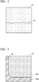
- FIG. 4 is a diagram which shows an example of a training image generated by an image generation device according to the embodiment.
- the image generator 13 generates a training image L1 shown in FIG. 4 , based on the first image P1 and the feature data.
- the image generator 13 deletes a hue from each pixel of the entire first image P1.
- the image generator 13 replaces the hue of each pixel of the entire first image P1 with a value related to a hue of each pixel in the region R21 of the second image P2 included in the feature data described above.
- the value related to the hue is, for example, an average of the hue.
- the image generator 13 adds noise defined by a value indicating a degree of variability in the hue of each pixel in the region R21 of the second image P2 included in the feature data described above to the hue of each pixel of the entire first image P1.
- the value indicating the degree of variability is a dispersion
- the noise is Gaussian noise defined by a mean and a dispersion of the hue of each pixel in the region R21 of the second image P2.
- the hue of each pixel of the entire first image P1 becomes close to the hue of the region R21 in which the second product in the second image P2 is depicted.
- the entire first image P1 referred to herein is an example of a region in which the first product in the first image P1 is depicted.
- the region in which the first product in the first image P1 is depicted may be a region in which the first defect included in the first product is depicted and a region in the vicinity thereof.
- the image generator 13 combines the boundary B with the first image P1 based on the boundary data included in the feature data described above, and combines the background depicted in the region R22 of the second image P2 with the first image P1 based on the background data included in the feature data described above. As described above, the image generator 13 generates the training image L1 shown in FIG. 4 .
- the image generator 13 may generate a training image L2 shown in FIG. 5 or a training image L3 shown in FIG. 6 by changing at least one of a position and a direction of the crack C1 that is an example of a first defect depicted by the first image P1 shown in FIG. 2 .
- FIGS. 5 and 6 are diagrams which show examples of training images generated by the image generation device according to the embodiment.
- the image generator 13 may execute hue replacement, noise addition, boundary combination, and background combination described above and generate the training image L2 shown in FIG. 5 after causing the position of the crack C1 to be translated using image processing to the first image P1 shown in FIG. 2 .
- the image generator 13 may cause the direction of the crack C1 to be rotated by 45 degrees counterclockwise by applying image processing to the first image P1 shown in FIG. 2 , and then execute the hue replacement, the noise addition, the boundary combination, and the background combination described above, and generate the training image L3 shown in FIG. 6 .
- the image storage unit 14 is a storage medium which stores the training image L1, the training image L2, and the training image L3 generated by the image generator 13.
- the identifier learning unit 15 causes the identifier 20 shown in FIG. 1 , to perform learning by causing it to be read a training image.
- the identifier 20 identifies whether an inspection image obtained by imaging a product to be inspected depicts the same type of defect as the first defect depicted by the first image P1 using machine learning.
- the machine learning referred to herein includes deep learning and is, for example, a neural network, a support vector machine (SVM), or a random forest.
- the inspection image is, for example, imaged by the imaging device 30 shown in FIG. 1 .
- the identifier learning unit 15 causes a training image for each type of a specific defect to be read with respect to each type of defect such as a crack, a chip, a hole, a dent, and adhesion of foreign matter.
- the identifier learning unit 15 may cause the identifier 20 to read a certain number of training images for each of crack features, such as a crack that is in a substantially straight line, a crack that branches in the middle, or a crack that is bent, with respect to a crack which is one type of defect.
- the identifier verifier 16 causes the identifier 20 to read an abnormal inspection image obtained by imaging a product to be inspected, which includes the same type of defect as the first defect depicted by the first image P1, and verifies an accuracy in identification by the identifier 20.
- the identifier verifier 16 depicts a crack that is in a substantially straight line such as the training image L1 shown in FIG. 4 , and causes the identifier 20 to read a certain number of training images or more generated from the first image P1 and the like shown in FIG. 2 .
- the identifier verifier 16 inputs the inspection image of a product to be inspected, which includes a crack that is in a substantially straight line to the identifier 20, and verifies whether the identifier 20 identifies that a crack in a substantially straight line is depicted in the inspection image.
- FIG. 7 is a flowchart which shows an example of processing executed by the image generation device according to the embodiment.
- step S10 the image generator 13 deletes a hue from each pixel of the first image P1, and determines a position and a direction of a first defect.
- step S20 the feature extractor 12 extracts the value related to the hue of each pixel in a region in which the second product in the second image P2 is depicted and the degree of variability in hue, and extracts boundary data indicating a boundary B between the second product and a background depicted by the second image P2 and background data indicating the background.
- step S30 the image generator 13 replaces a hue of each pixel in the region in which at least a first product in the first image P1 is depicted with the value related to the hue, which is extracted in step S20.
- step S40 the image generator 13 adds noise defined by the value related to the hue and the degree of variability in hue extracted in step S20 to a hue of each pixel in the region in which at least the first product of the first image P1 is depicted.
- step S50 the image generator 13 combines the region R22 of the second image P2 depicting the boundary B and the background with the first image P1 based on the boundary data and the background data extracted in step S20.
- the image generation device 10 generates at least one of a training image L1, a training image L2, and a training image L3 based on the first image P1 depicting the first defect included in the first product.
- the image generation device 10 can increase the number of types of training image and contribute to improving the accuracy in identification by the identifier 20.
- the image generation device 10 extracts feature data indicating the features of the second image P2, and generates at least one of the training image L1, the training image L2, and the training image L3 based on the first image P1 and the feature data.
- the image generation device 10 can bring features of the training image L1, the training image L2, and the training image L3 close to features of an inspection image of a product to be inspected and contribute to improving the accuracy in identification by the identifier 20, even though features of the first image P1 are different from features of the second image.
- the image generation device 10 extracts the value related to the hue of each pixel in the region R21 in which the second product in the second image P2 is depicted and the value indicating the degree of variability in the hue. Then, the image generation device 10 replaces the hue of each pixel in the region in which at least the first product of the first image P1 is depicted with the value related to the hue of each pixel in the region R21, and adds noise defined by the value indicating the degree of the variability in hue of each pixel in the region R21 to the hue of each pixel in the region in which at least the first product in the first image P1 is depicted.
- the image generation device 10 can bring the hues of the training image L1, the training image L2, and the training image L3 close to the hue of the inspection image of a product to be inspected and contribute to improving the accuracy in identification by the identifier 20, even though a hue of the first image P1 is different from a hue of the second image.
- the image generation device 10 extracts boundary data indicating the boundary B between the second product and the background depicted by the second image P2, and combines the boundary B with the first image P1 based on the boundary data. Furthermore, the image generation device 10 extracts background data indicating the background of the second product depicted by the second image P2, and combines the background with the first image P1 based on the background data. According to these two types of processing, the image generation device 10 can bring the features of these training images close to the features of the inspection image of a product to be inspected by including the boundary B and the background in the training image L1, the training image L2, and the training image L3, and contribute to improving the accuracy in identification by the identifier 20. In particular, when the boundary and the background are easily recognized as the features by the identifier 20, these two types of processing are useful because the features of these training images become further closer to the feature of the image to be inspected.
- the image generation device 10 generates a training image L2 and a training image L3 by changing at least one of the position and the direction of the first defect depicted by the first image P1.
- the image generation device 10 can generate two training images L2 and L3 in addition to the training image L1 from one first image P1, it is possible to contribute to improving the accuracy in identification by the identifier 20 by further increasing the types of training images.
- the first product and the second product are different types of product.
- the image generation device 10 can generate at least one of the training image L1, the training image L2, and the training image L3 from the first image P1 obtained by imaging the first defect included in the first product even though the number of images depicting a defect included in the second product is small. Therefore, it is possible to increase the number of types of training image and to contribute to improvement of the identification accuracy of the identifier 20.
- the image generation device 10 causes the identifier 20 to read the training image L1, the training image L2, and the training image L3 and causes the identifier 20 to perform learning. Then, the image generation device 10 causes the identifier 20 to read an abnormal inspection image obtained by imaging a product to be inspected, which includes the same type of defect as the first defect depicted by the first image P1, and verifies the accuracy in the identification by the identifier 20. Therefore, the image generation device 10 can not only verify how much the accuracy in identification by the identifier 20 is improved but also guide learning by the identifier 20 using the training image L1, the training image L2, and the training image L3 in a better direction.
- the image generator 13 may generate a training image based on the first image P1 without using feature data indicating the features of the second image P2. In this case, the image generator 13 generates a training image by deleting data indicating the hue of each pixel in a region in which at least the first defect included in the first product in the first image P1 is depicted.
- the image acquisition unit 11 may acquire a third image depicting the second defect that is the same type of defect as the first defect and is included in the second product, separately from the first image.
- the image generator 13 generates a training image on the basis of the third image separately from the training images generated on the basis of the first image P1.
- the image generator 13 generates a training image by changing at least one of the position and direction of the second defect depicted by the third image according to processing in which the position of the second defect is caused to be parallel translated by applying image processing to the third image or processing in which the direction of the second defect is rotated. Therefore, the image generation device 10 can further increase the types of training images and contribute to improving the accuracy in identification by the identifier 20.
- the abnormal inspection image described above may include not only an inspection image acquired separately from the training images but also at least one of the first image and the third image.
Landscapes
- Engineering & Computer Science (AREA)
- Physics & Mathematics (AREA)
- General Physics & Mathematics (AREA)
- Theoretical Computer Science (AREA)
- Computer Vision & Pattern Recognition (AREA)
- Life Sciences & Earth Sciences (AREA)
- Quality & Reliability (AREA)
- Health & Medical Sciences (AREA)
- Pathology (AREA)
- Immunology (AREA)
- General Health & Medical Sciences (AREA)
- Biochemistry (AREA)
- Analytical Chemistry (AREA)
- Chemical & Material Sciences (AREA)
- Data Mining & Analysis (AREA)
- Signal Processing (AREA)
- General Engineering & Computer Science (AREA)
- Evolutionary Computation (AREA)
- Evolutionary Biology (AREA)
- Bioinformatics & Computational Biology (AREA)
- Bioinformatics & Cheminformatics (AREA)
- Artificial Intelligence (AREA)
- Image Analysis (AREA)
- Investigating Materials By The Use Of Optical Means Adapted For Particular Applications (AREA)
- Image Processing (AREA)
Abstract
Description
- Priority is claimed on Japanese Patent Application No.
2018-247016, filed December 28, 2018 - The present invention relates to an image generation device and an appearance inspection device.
- At present, as artificial intelligence (AI) is being rapidly developed, the importance of machine learning including deep learning has increased, and it is expected to be applied to many fields such as in manufacturing and service industries.
- For example, when machine learning is applied in the manufacturing industry, a training image obtained by imaging a non-defective product and a training image obtained by imaging a defective product are required, in order to perform learning of an identifier that identifies whether a product is a non-defective product not containing a defect or a defective product containing a defect. In addition, to improve accuracy in identification by an identifier, it is necessary to prepare a certain number or more of both training images obtained by imaging non-defective products and training images obtained by imaging defective products, to prepare a same number of both training images obtained by imaging non-defective products and training images obtained by imaging defective products.
- However, the number of defective products is usually much smaller than the number of non-defective products. For this reason, there are often insufficient training images obtained by imaging defective products as compared to training images obtained by imaging non-defective products. As a technology for solving this problem, for example, Patent Document 1 discloses a pseudo-defective image automatic creation device. The pseudo-defective image automatic creation device extracts a difference data from non-defective products. The pseudo-defective image automatic creation device creates some defect creation conditions such as a defective combination position based on random values. The pseudo-defective image automatic creation device creates some pseudo-defective images by combining the difference data with the non-defective images based on these defect creation conditions. And the pseudo-defective image automatic creation device inputs the pseudo-defective images to a neural network as training images obtained by imaging defective products.
- [Patent Document 1] Japanese Unexamined Patent Application, Second Publication No.
2005-156334 - However, since the pseudo-defective image automatic creation device creates a plurality of pseudo-defective images from a small number of training images obtained by imaging defective products in a pseudo manner, the types of pseudo-defective image may be few, and the accuracy in identification by an identifier may not be sufficiently increased.
- Therefore, an object of the present invention is to provide an image generation device and an appearance inspection device that can increase the number of types of training image.
- According to one aspect of the present invention, an image generation device includes an image acquisition unit configured to acquire a first image; and an image generator configured to generate a training image based on the first image, wherein the first image depicts a first defect included in a first product of a different type the product to be inspected, and the training image is a image to be read by an identifier that identifies whether an inspection image obtained by imaging the product to be inspected depicts the same type of defect as the first defect and to be used by the identifier to perform learning.
- According to the present invention, it is possible to increase the number of types of training image.
-
-
FIG. 1 is a diagram which shows an example of a configuration of an appearance inspection device according to an embodiment. -
FIG. 2 is a diagram which shows an example of a first image according to the embodiment. -
FIG. 3 is a diagram which shows an example of a second image according to the embodiment. -
FIG. 4 is a diagram which shows an example of a training image generated by an image generation device according to the embodiment. -
FIG. 5 is a diagram which shows an example of a training image generated by the image generation device according to the embodiment. -
FIG. 6 is a diagram which shows an example of a training image generated by the image generation device according to the embodiment. -
FIG. 7 is a flowchart which shows an example of processing executed by the image generation device according to the embodiment. - An example of a configuration of an appearance inspection device according to an embodiment will be described, focusing on an image generation device with reference to
FIGS. 1 to 6 .FIG. 1 is a diagram which shows the example of the configuration of the appearance inspection device according to the embodiment. As shown inFIG. 1 , an appearance inspection device 1 includes animage generation device 10, anidentifier 20, and animaging device 30. - The
image generation device 10 includes animage acquisition unit 11, afeature extractor 12, animage generator 13, animage storage unit 14, anidentifier learning unit 15, and anidentifier verifier 16. -
FIG. 2 is a diagram which shows an example of a first image according to the embodiment. Theimage acquisition unit 11 acquires a first image P1 depicting a first defect included in a first product. The first product is a different type of product from a product to be inspected. In addition, the first defect is a defect such as a crack, a chip, a hole, a dent, or adhesion of foreign matter. As shown inFIG. 2 , the first image P1 depicts a first product including a substantially straight crack C1. Theimage acquisition unit 11 acquires, for example, a first image P1 from a storage medium provided inside or outside of the appearance inspection device 1. -
FIG. 3 is a diagram which shows an example of a second image according to the embodiment. Thefeature extractor 12 images the second product, which is the same as a type of a product to be inspected, and extracts feature data indicating features of the second image P2 not depicting a defect from the second image P2. In addition, the first product and the second product are different types of product. For example, the first product is a resin product and the second product is a ceramic product. - In addition, the feature data includes values related to a hue of each pixel in a region in which the second product of the second image P2 is depicted, and values indicating a degree of variability in the hue. The region is, for example, a region R21 shown in
FIG. 3 . The values related to a hue are, for example, an average, a median, a maximum value, and a minimum value of the hue, and values obtained by performing appropriate correction and weighting on these values. The values indicating a degree of variability in hue are, for example, a dispersion and a standard deviation of the hue. - Alternatively, the feature data may include boundary data indicating a boundary B between a second product and a background depicted by the second image P2. As shown in
FIG. 3 , the boundary B is a line that separates the region R21 from a region R22. For example, thefeature extractor 12 may extract boundary data indicating the boundary B by applying edge detection to the second image P2. However, thefeature extractor 12 may extract the boundary data with a method other than edge detection. - Alternatively, the feature data may include background data indicating a background of the second product depicted by the second image P2. The background is depicted in the region R22 of the second image P2. For example, the
feature extractor 12 extracts the background data indicating the background by applying image recognition to the second image P2. Specifically, when thefeature extractor 12 extracts the background data from the second image P2, thefeature extractor 12 recognizes the region R21 and the region R22 using the boundary data indicating the boundary B, recognizes the background as being depicted in the region R22 by applying image recognition to each of the region R21 and the region R22, and extracts the background data from the region R22. However, thefeature extractor 12 may recognize the region R21 and the region R22 with other methods or may recognize that the background is depicted in the region R22 with other methods. -
FIG. 4 is a diagram which shows an example of a training image generated by an image generation device according to the embodiment. Theimage generator 13 generates a training image L1 shown inFIG. 4 , based on the first image P1 and the feature data. - First, the
image generator 13 deletes a hue from each pixel of the entire first image P1. Next, theimage generator 13 replaces the hue of each pixel of the entire first image P1 with a value related to a hue of each pixel in the region R21 of the second image P2 included in the feature data described above. In this case, the value related to the hue is, for example, an average of the hue. Furthermore, theimage generator 13 adds noise defined by a value indicating a degree of variability in the hue of each pixel in the region R21 of the second image P2 included in the feature data described above to the hue of each pixel of the entire first image P1. In this case, for example, the value indicating the degree of variability is a dispersion, and the noise is Gaussian noise defined by a mean and a dispersion of the hue of each pixel in the region R21 of the second image P2. According to these two types of processing, the hue of each pixel of the entire first image P1 becomes close to the hue of the region R21 in which the second product in the second image P2 is depicted. Note that the entire first image P1 referred to herein is an example of a region in which the first product in the first image P1 is depicted. In addition, the region in which the first product in the first image P1 is depicted may be a region in which the first defect included in the first product is depicted and a region in the vicinity thereof. - Then, the
image generator 13 combines the boundary B with the first image P1 based on the boundary data included in the feature data described above, and combines the background depicted in the region R22 of the second image P2 with the first image P1 based on the background data included in the feature data described above. As described above, theimage generator 13 generates the training image L1 shown inFIG. 4 . - Moreover, the
image generator 13 may generate a training image L2 shown inFIG. 5 or a training image L3 shown inFIG. 6 by changing at least one of a position and a direction of the crack C1 that is an example of a first defect depicted by the first image P1 shown inFIG. 2 .FIGS. 5 and6 are diagrams which show examples of training images generated by the image generation device according to the embodiment. - For example, the
image generator 13 may execute hue replacement, noise addition, boundary combination, and background combination described above and generate the training image L2 shown inFIG. 5 after causing the position of the crack C1 to be translated using image processing to the first image P1 shown inFIG. 2 . - Alternatively, the
image generator 13 may cause the direction of the crack C1 to be rotated by 45 degrees counterclockwise by applying image processing to the first image P1 shown inFIG. 2 , and then execute the hue replacement, the noise addition, the boundary combination, and the background combination described above, and generate the training image L3 shown inFIG. 6 . - The
image storage unit 14 is a storage medium which stores the training image L1, the training image L2, and the training image L3 generated by theimage generator 13. - The
identifier learning unit 15 causes theidentifier 20 shown inFIG. 1 , to perform learning by causing it to be read a training image. - The
identifier 20 identifies whether an inspection image obtained by imaging a product to be inspected depicts the same type of defect as the first defect depicted by the first image P1 using machine learning. The machine learning referred to herein includes deep learning and is, for example, a neural network, a support vector machine (SVM), or a random forest. In addition, the inspection image is, for example, imaged by theimaging device 30 shown inFIG. 1 . - The
identifier learning unit 15 causes a training image for each type of a specific defect to be read with respect to each type of defect such as a crack, a chip, a hole, a dent, and adhesion of foreign matter. For example, theidentifier learning unit 15 may cause theidentifier 20 to read a certain number of training images for each of crack features, such as a crack that is in a substantially straight line, a crack that branches in the middle, or a crack that is bent, with respect to a crack which is one type of defect. - The
identifier verifier 16 causes theidentifier 20 to read an abnormal inspection image obtained by imaging a product to be inspected, which includes the same type of defect as the first defect depicted by the first image P1, and verifies an accuracy in identification by theidentifier 20. For example, theidentifier verifier 16 depicts a crack that is in a substantially straight line such as the training image L1 shown inFIG. 4 , and causes theidentifier 20 to read a certain number of training images or more generated from the first image P1 and the like shown inFIG. 2 . Then, theidentifier verifier 16 inputs the inspection image of a product to be inspected, which includes a crack that is in a substantially straight line to theidentifier 20, and verifies whether theidentifier 20 identifies that a crack in a substantially straight line is depicted in the inspection image. - Next, an example of operations of the image generation device according to the embodiment will be described with reference to
FIG. 7. FIG. 7 is a flowchart which shows an example of processing executed by the image generation device according to the embodiment. - In step S10, the
image generator 13 deletes a hue from each pixel of the first image P1, and determines a position and a direction of a first defect. - In step S20, the
feature extractor 12 extracts the value related to the hue of each pixel in a region in which the second product in the second image P2 is depicted and the degree of variability in hue, and extracts boundary data indicating a boundary B between the second product and a background depicted by the second image P2 and background data indicating the background. - In step S30, the
image generator 13 replaces a hue of each pixel in the region in which at least a first product in the first image P1 is depicted with the value related to the hue, which is extracted in step S20. - In step S40, the
image generator 13 adds noise defined by the value related to the hue and the degree of variability in hue extracted in step S20 to a hue of each pixel in the region in which at least the first product of the first image P1 is depicted. - In step S50, the
image generator 13 combines the region R22 of the second image P2 depicting the boundary B and the background with the first image P1 based on the boundary data and the background data extracted in step S20. - As described above, the
image generation device 10 according to the embodiment has been described. Theimage generation device 10 generates at least one of a training image L1, a training image L2, and a training image L3 based on the first image P1 depicting the first defect included in the first product. As a result, theimage generation device 10 can increase the number of types of training image and contribute to improving the accuracy in identification by theidentifier 20. - In addition, the
image generation device 10 extracts feature data indicating the features of the second image P2, and generates at least one of the training image L1, the training image L2, and the training image L3 based on the first image P1 and the feature data. As a result, theimage generation device 10 can bring features of the training image L1, the training image L2, and the training image L3 close to features of an inspection image of a product to be inspected and contribute to improving the accuracy in identification by theidentifier 20, even though features of the first image P1 are different from features of the second image. - In addition, the
image generation device 10 extracts the value related to the hue of each pixel in the region R21 in which the second product in the second image P2 is depicted and the value indicating the degree of variability in the hue. Then, theimage generation device 10 replaces the hue of each pixel in the region in which at least the first product of the first image P1 is depicted with the value related to the hue of each pixel in the region R21, and adds noise defined by the value indicating the degree of the variability in hue of each pixel in the region R21 to the hue of each pixel in the region in which at least the first product in the first image P1 is depicted. As a result, theimage generation device 10 can bring the hues of the training image L1, the training image L2, and the training image L3 close to the hue of the inspection image of a product to be inspected and contribute to improving the accuracy in identification by theidentifier 20, even though a hue of the first image P1 is different from a hue of the second image. - Moreover, the
image generation device 10 extracts boundary data indicating the boundary B between the second product and the background depicted by the second image P2, and combines the boundary B with the first image P1 based on the boundary data. Furthermore, theimage generation device 10 extracts background data indicating the background of the second product depicted by the second image P2, and combines the background with the first image P1 based on the background data. According to these two types of processing, theimage generation device 10 can bring the features of these training images close to the features of the inspection image of a product to be inspected by including the boundary B and the background in the training image L1, the training image L2, and the training image L3, and contribute to improving the accuracy in identification by theidentifier 20. In particular, when the boundary and the background are easily recognized as the features by theidentifier 20, these two types of processing are useful because the features of these training images become further closer to the feature of the image to be inspected. - In addition, the
image generation device 10 generates a training image L2 and a training image L3 by changing at least one of the position and the direction of the first defect depicted by the first image P1. As a result, since theimage generation device 10 can generate two training images L2 and L3 in addition to the training image L1 from one first image P1, it is possible to contribute to improving the accuracy in identification by theidentifier 20 by further increasing the types of training images. - The first product and the second product are different types of product. For this reason, the
image generation device 10 can generate at least one of the training image L1, the training image L2, and the training image L3 from the first image P1 obtained by imaging the first defect included in the first product even though the number of images depicting a defect included in the second product is small. Therefore, it is possible to increase the number of types of training image and to contribute to improvement of the identification accuracy of theidentifier 20. - In addition, the
image generation device 10 causes theidentifier 20 to read the training image L1, the training image L2, and the training image L3 and causes theidentifier 20 to perform learning. Then, theimage generation device 10 causes theidentifier 20 to read an abnormal inspection image obtained by imaging a product to be inspected, which includes the same type of defect as the first defect depicted by the first image P1, and verifies the accuracy in the identification by theidentifier 20. Therefore, theimage generation device 10 can not only verify how much the accuracy in identification by theidentifier 20 is improved but also guide learning by theidentifier 20 using the training image L1, the training image L2, and the training image L3 in a better direction. - Note that the
image generator 13 may generate a training image based on the first image P1 without using feature data indicating the features of the second image P2. In this case, theimage generator 13 generates a training image by deleting data indicating the hue of each pixel in a region in which at least the first defect included in the first product in the first image P1 is depicted. - Note that the
image acquisition unit 11 may acquire a third image depicting the second defect that is the same type of defect as the first defect and is included in the second product, separately from the first image. In this case, theimage generator 13 generates a training image on the basis of the third image separately from the training images generated on the basis of the first image P1. Alternatively, theimage generator 13 generates a training image by changing at least one of the position and direction of the second defect depicted by the third image according to processing in which the position of the second defect is caused to be parallel translated by applying image processing to the third image or processing in which the direction of the second defect is rotated. Therefore, theimage generation device 10 can further increase the types of training images and contribute to improving the accuracy in identification by theidentifier 20. - Note that the abnormal inspection image described above may include not only an inspection image acquired separately from the training images but also at least one of the first image and the third image.
- While preferred embodiments of the invention have been described and illustrated above, it should be understood that these are exemplary of the invention and are not to be considered as limiting. Additions, omissions, substitutions, and other modifications can be made without departing from the spirit or scope of the present invention. Accordingly, the invention is not to be considered as being limited by the foregoing description, and is only limited by the scope of the appended claims.
-
- 1
- Appearance inspection device
- 10
- Image generation device
- 11
- Image acquisition unit
- 12
- Feature extractor
- 13
- Image generator
- 14
- Image storage unit
- 15
- Identifier learning unit
- 16
- Identifier verifier
- 20
- Identifier
- 30
- Imaging device
- B
- Boundary
- C1
- Crack
- L1, L2, L3
- Training image
- P1
- First image
- P2
- Second image
- R21, R22
- Region
Claims (11)
- An image generation device comprising:an image acquisition unit configured to acquire a first image; andan image generator configured to generate a training image based on the first image,wherein the first image depicts a first defect included in a first product of a different type the product to be inspected, andthe training image is a image to be read by an identifier that identifies whether an inspection image obtained by imaging the product to be inspected depicts a same type of defect as the first defect and to be used by the identifier to perform learning.
- The image generation device according to claim 1, further comprising:a feature extractor configured to image a second product, and extract feature data from the second image,wherein the second product is a same type of a product as the product to be inspected,the feature data indicates a feature of the second image not depicting a defect, andthe image generator generates the training image based on the feature data in addition to the first image.
- The image generation device according to claim 2,wherein the feature extractor extracts a value as the feature data,the value relates to a hue of each pixel in a region in which the second product of the second image is depicted, andthe image generator replaces a hue of each pixel in a region in which the first product in the first image is depicted with the value.
- The image generation device according to claim 2 or 3,wherein the feature extractor extracts a value as the feature data,the value indicates a degree of variability in hue of each pixel in a region in which the second product in the second image is depicted, andthe image generator adds noise defined by the value to a hue of each pixel in a region in which the first product in the first image is depicted.
- The image generation device according to claim 2 - 4,wherein the feature extractor extracts a background data as the feature data,the background data indicates a background of the second product depicted by the second image, andthe image generator combines the background with the first image on the basis of the background data.
- The image generation device according to claim 5,wherein the feature extractor extracts a boundary data as the feature data,the boundary data indicates a boundary between the second product and the background depicted by the second image, andthe image generator combines the boundary with the first image based on the boundary data.
- The image generation device according to claim 2 - 6,wherein the image acquisition unit further acquires a third image depicting a second defect included in the second product,the second defect is the same type of defect as the first defect, andthe image generator further generates the training images based on the third image.
- The image generation device according to claim 7,
wherein the image generator generates the training images by changing at least one of a position and a direction of the second defect depicted by the third image. - The image generation device according to claim 1 - 8,
wherein the image generator generates the training images by changing at least one of a position and a direction of the first defect depicted by the first image. - The image generation device according to claim 1 - 9, further comprising:an identifier learning unit configured to cause the identifier to read the training images and to perform learning; andan identifier verifier configured to cause the identifier to read an abnormal inspection image obtained by imaging the product to be inspected, which includes the same type of defect as the first defect, and to verify an accuracy in identification by the identifier.
- An appearance inspection device comprising:an imaging device configured to image a product to be inspected; andan identifier which has performed learning by reading the training image generated by the image generation device according to claim 1 - 9.
Applications Claiming Priority (1)
| Application Number | Priority Date | Filing Date | Title |
|---|---|---|---|
| JP2018247016A JP6908019B2 (en) | 2018-12-28 | 2018-12-28 | Image generator and visual inspection device |
Publications (2)
| Publication Number | Publication Date |
|---|---|
| EP3675033A1 true EP3675033A1 (en) | 2020-07-01 |
| EP3675033B1 EP3675033B1 (en) | 2026-05-20 |
Family
ID=69104228
Family Applications (1)
| Application Number | Title | Priority Date | Filing Date |
|---|---|---|---|
| EP19217551.1A Active EP3675033B1 (en) | 2018-12-28 | 2019-12-18 | IMAGE PROCESSING DEVICE AND DEVICE FOR EXAMINING APPEARANCE |
Country Status (3)
| Country | Link |
|---|---|
| US (1) | US11373292B2 (en) |
| EP (1) | EP3675033B1 (en) |
| JP (1) | JP6908019B2 (en) |
Cited By (1)
| Publication number | Priority date | Publication date | Assignee | Title |
|---|---|---|---|---|
| US20240104904A1 (en) * | 2021-04-20 | 2024-03-28 | Huawei Cloud Computing Technologies Co., Ltd. | Fault image generation method and apparatus |
Families Citing this family (11)
| Publication number | Priority date | Publication date | Assignee | Title |
|---|---|---|---|---|
| JP6792842B2 (en) * | 2017-06-06 | 2020-12-02 | 株式会社デンソー | Visual inspection equipment, conversion data generation equipment, and programs |
| CN116420161A (en) * | 2020-11-10 | 2023-07-11 | 松下知识产权经营株式会社 | Data creation system, learning system, estimation system, processing device, data creation method and program |
| WO2022102525A1 (en) * | 2020-11-10 | 2022-05-19 | パナソニックIpマネジメント株式会社 | Data creation system, learning system, estimation system, processing device, evaluation system, data creation method, and program |
| WO2022102523A1 (en) * | 2020-11-10 | 2022-05-19 | パナソニックIpマネジメント株式会社 | Data creation system, learning system, inference system, processing device, assessment system, data creation method, and program |
| CN114663337B (en) * | 2020-12-23 | 2025-04-25 | 株式会社理光 | Neural network training method and defect detection method, device and storage medium |
| CN115294007A (en) * | 2021-04-20 | 2022-11-04 | 华为云计算技术有限公司 | Fault image generation method and device |
| JP7741654B2 (en) * | 2021-06-24 | 2025-09-18 | キヤノン株式会社 | Learning device, image processing device, learning processing method, and program |
| JP7770168B2 (en) * | 2021-11-24 | 2025-11-14 | 株式会社キーエンス | Appearance inspection device and appearance inspection method |
| KR102760241B1 (en) * | 2021-12-17 | 2025-01-31 | 모니텍주식회사 | System for welding quality monitoring and method thereof |
| WO2024028971A1 (en) * | 2022-08-02 | 2024-02-08 | 日本たばこ産業株式会社 | Foreign substance inspection device |
| WO2025074514A1 (en) | 2023-10-03 | 2025-04-10 | 株式会社Rist | Method, program, information processing device, and trained model |
Citations (1)
| Publication number | Priority date | Publication date | Assignee | Title |
|---|---|---|---|---|
| US20180365822A1 (en) * | 2017-06-19 | 2018-12-20 | ImpactVision, Inc. | System and method for hyperspectral image processing to identify foreign object |
Family Cites Families (8)
| Publication number | Priority date | Publication date | Assignee | Title |
|---|---|---|---|---|
| US7602962B2 (en) * | 2003-02-25 | 2009-10-13 | Hitachi High-Technologies Corporation | Method of classifying defects using multiple inspection machines |
| JP2005156334A (en) | 2003-11-25 | 2005-06-16 | Nec Tohoku Sangyo System Kk | Pseudo defective image automatic creation device and imaging inspection device |
| JP4513962B2 (en) * | 2005-01-12 | 2010-07-28 | 横河電機株式会社 | Pseudo defect image creation method and apparatus using the same |
| JP5327973B2 (en) * | 2007-12-05 | 2013-10-30 | 芝浦メカトロニクス株式会社 | Feature analyzer |
| JP5546317B2 (en) * | 2010-03-31 | 2014-07-09 | 株式会社デンソーアイティーラボラトリ | Visual inspection device, visual inspection discriminator generation device, visual inspection discriminator generation method, and visual inspection discriminator generation computer program |
| CN105118044B (en) * | 2015-06-16 | 2017-11-07 | 华南理工大学 | A kind of wheel shape cast article defect automatic testing method |
| JP7254324B2 (en) * | 2017-06-05 | 2023-04-10 | 学校法人梅村学園 | IMAGE GENERATING APPARATUS AND IMAGE GENERATING METHOD FOR GENERATING INSPECTION IMAGE FOR PERFORMANCE ADJUSTMENT OF IMAGE INSPECTION SYSTEM |
| CA3083095A1 (en) * | 2017-11-21 | 2019-05-31 | Fulfil Solutions, Inc. | Product handling and packaging system |
-
2018
- 2018-12-28 JP JP2018247016A patent/JP6908019B2/en active Active
-
2019
- 2019-12-18 EP EP19217551.1A patent/EP3675033B1/en active Active
- 2019-12-19 US US16/720,474 patent/US11373292B2/en active Active
Patent Citations (1)
| Publication number | Priority date | Publication date | Assignee | Title |
|---|---|---|---|---|
| US20180365822A1 (en) * | 2017-06-19 | 2018-12-20 | ImpactVision, Inc. | System and method for hyperspectral image processing to identify foreign object |
Non-Patent Citations (2)
| Title |
|---|
| AYSEGUL DUNDAR ET AL: "Context Augmentation for Convolutional Neural Networks", ARXIV.ORG, CORNELL UNIVERSITY LIBRARY, 201 OLIN LIBRARY CORNELL UNIVERSITY ITHACA, NY 14853, 23 November 2017 (2017-11-23), XP080844858 * |
| MOHD Z ABDULLAH ' ET AL: "COLOR VISION SYSTEM FOR RIPENESS INSPECTION OF OIL PALM ELAEIS GUINEENSZS", 2 April 2002 (2002-04-02), XP055327721, Retrieved from the Internet <URL:http://onlinelibrary.wiley.com/store/10.1111/j.1745-4549.2002.tb00481.x/asset/j.1745-4549.2002.tb00481.x.pdf?v=1&t=iwho6drv&s=3a8d9f9aa6fd3bf8f52bdafdc1a0458f49e3c4cd> [retrieved on 20161209] * |
Cited By (2)
| Publication number | Priority date | Publication date | Assignee | Title |
|---|---|---|---|---|
| US20240104904A1 (en) * | 2021-04-20 | 2024-03-28 | Huawei Cloud Computing Technologies Co., Ltd. | Fault image generation method and apparatus |
| EP4307217A4 (en) * | 2021-04-20 | 2024-08-14 | Huawei Cloud Computing Technologies Co., Ltd. | Fault image generation method and apparatus |
Also Published As
| Publication number | Publication date |
|---|---|
| US11373292B2 (en) | 2022-06-28 |
| US20200211169A1 (en) | 2020-07-02 |
| JP6908019B2 (en) | 2021-07-21 |
| JP2020106461A (en) | 2020-07-09 |
| EP3675033B1 (en) | 2026-05-20 |
Similar Documents
| Publication | Publication Date | Title |
|---|---|---|
| US11373292B2 (en) | Image generation device and appearance inspection device | |
| US11797886B2 (en) | Image processing device, image processing method, and image processing program | |
| US12243218B2 (en) | Method and system for scanning wafer | |
| US9811899B2 (en) | Method, image processing system and computer-readable recording medium for item defect inspection | |
| CN110599484B (en) | Defect detection method, device and storage medium | |
| US8908957B2 (en) | Method for building rule of thumb of defect classification, and methods for classifying defect and judging killer defect based on rule of thumb and critical area analysis | |
| US20170316558A1 (en) | Image processing apparatus, image processing method and storage medium | |
| US10922801B2 (en) | Channel-based binarization of color | |
| US11151706B2 (en) | Method of classifying defects in a semiconductor specimen and system thereof | |
| US11922680B2 (en) | Image determination device, image determination method, and non-transitory computer readable medium storing program | |
| KR20170109304A (en) | Method for parallel learning of cascade classifier by object recognition | |
| WO2015171654A1 (en) | Automatic calibration sample selection for die-to-database photomask inspection | |
| US20240177297A1 (en) | Apparatus and method for detecting defect using deep learning-based surface inspection | |
| CN111986176A (en) | Crack image identification method, system, terminal and readable storage medium | |
| Zhang et al. | Automated defect recognition of C-SAM images in IC packaging using Support Vector Machines | |
| JP2009157701A (en) | Image processing method and image processing apparatus | |
| US11361424B2 (en) | Neural network-type image processing device, appearance inspection apparatus and appearance inspection method | |
| US20130080137A1 (en) | Conversion method and system | |
| US8781182B2 (en) | Multi-pass edge detection of collimator blades in digital radiography images | |
| CN110796050A (en) | Target object identification method and related device in unmanned aerial vehicle inspection process | |
| US12242500B2 (en) | Data processing method and data comparing method | |
| Dovgan et al. | Detection of irregularities on automotive semiproducts | |
| JP6902396B2 (en) | Manufacturing equipment with image classification function | |
| KR20260062821A (en) | Method, apparatus and computer program for quality inspection of printed circuit boards (pcb) based on deep learning and computer vision algorithms | |
| KR20260061749A (en) | Image based Inspection Device and Method therefor |
Legal Events
| Date | Code | Title | Description |
|---|---|---|---|
| PUAI | Public reference made under article 153(3) epc to a published international application that has entered the european phase |
Free format text: ORIGINAL CODE: 0009012 |
|
| STAA | Information on the status of an ep patent application or granted ep patent |
Free format text: STATUS: THE APPLICATION HAS BEEN PUBLISHED |
|
| AK | Designated contracting states |
Kind code of ref document: A1 Designated state(s): AL AT BE BG CH CY CZ DE DK EE ES FI FR GB GR HR HU IE IS IT LI LT LU LV MC MK MT NL NO PL PT RO RS SE SI SK SM TR |
|
| AX | Request for extension of the european patent |
Extension state: BA ME |
|
| STAA | Information on the status of an ep patent application or granted ep patent |
Free format text: STATUS: REQUEST FOR EXAMINATION WAS MADE |
|
| 17P | Request for examination filed |
Effective date: 20201218 |
|
| RBV | Designated contracting states (corrected) |
Designated state(s): AL AT BE BG CH CY CZ DE DK EE ES FI FR GB GR HR HU IE IS IT LI LT LU LV MC MK MT NL NO PL PT RO RS SE SI SK SM TR |
|
| STAA | Information on the status of an ep patent application or granted ep patent |
Free format text: STATUS: EXAMINATION IS IN PROGRESS |
|
| 17Q | First examination report despatched |
Effective date: 20220307 |
|
| GRAP | Despatch of communication of intention to grant a patent |
Free format text: ORIGINAL CODE: EPIDOSNIGR1 |
|
| STAA | Information on the status of an ep patent application or granted ep patent |
Free format text: STATUS: GRANT OF PATENT IS INTENDED |
|
| INTG | Intention to grant announced |
Effective date: 20251218 |
|
| GRAS | Grant fee paid |
Free format text: ORIGINAL CODE: EPIDOSNIGR3 |
|
| GRAA | (expected) grant |
Free format text: ORIGINAL CODE: 0009210 |
|
| STAA | Information on the status of an ep patent application or granted ep patent |
Free format text: STATUS: THE PATENT HAS BEEN GRANTED |