EP3674972A1 - Procédés et systèmes pour générer des données de formation pour un réseau neuronal - Google Patents
Procédés et systèmes pour générer des données de formation pour un réseau neuronal Download PDFInfo
- Publication number
- EP3674972A1 EP3674972A1 EP19209570.1A EP19209570A EP3674972A1 EP 3674972 A1 EP3674972 A1 EP 3674972A1 EP 19209570 A EP19209570 A EP 19209570A EP 3674972 A1 EP3674972 A1 EP 3674972A1
- Authority
- EP
- European Patent Office
- Prior art keywords
- digital image
- odnn
- detection
- given object
- moment
- Prior art date
- Legal status (The legal status is an assumption and is not a legal conclusion. Google has not performed a legal analysis and makes no representation as to the accuracy of the status listed.)
- Granted
Links
- 238000012549 training Methods 0.000 title claims abstract description 91
- 238000000034 method Methods 0.000 title claims abstract description 76
- 238000013528 artificial neural network Methods 0.000 title claims abstract description 20
- 238000001514 detection method Methods 0.000 claims abstract description 133
- 230000004044 response Effects 0.000 claims abstract description 14
- 238000004458 analytical method Methods 0.000 claims description 20
- 238000005516 engineering process Methods 0.000 description 82
- 238000004891 communication Methods 0.000 description 20
- 230000004807 localization Effects 0.000 description 9
- 230000006870 function Effects 0.000 description 6
- 238000012986 modification Methods 0.000 description 6
- 230000004048 modification Effects 0.000 description 6
- 230000009471 action Effects 0.000 description 4
- 238000010586 diagram Methods 0.000 description 4
- 238000003860 storage Methods 0.000 description 4
- 230000008569 process Effects 0.000 description 3
- 238000012545 processing Methods 0.000 description 3
- 238000009826 distribution Methods 0.000 description 2
- 238000010801 machine learning Methods 0.000 description 2
- 238000004519 manufacturing process Methods 0.000 description 2
- 239000012092 media component Substances 0.000 description 2
- 241001465754 Metazoa Species 0.000 description 1
- 238000013459 approach Methods 0.000 description 1
- 230000008859 change Effects 0.000 description 1
- 238000007906 compression Methods 0.000 description 1
- 230000006835 compression Effects 0.000 description 1
- 238000004590 computer program Methods 0.000 description 1
- 230000001143 conditioned effect Effects 0.000 description 1
- 238000013527 convolutional neural network Methods 0.000 description 1
- 238000013135 deep learning Methods 0.000 description 1
- 238000001914 filtration Methods 0.000 description 1
- 239000000446 fuel Substances 0.000 description 1
- 238000003384 imaging method Methods 0.000 description 1
- 230000000116 mitigating effect Effects 0.000 description 1
- 210000002569 neuron Anatomy 0.000 description 1
- 238000010606 normalization Methods 0.000 description 1
- 238000011176 pooling Methods 0.000 description 1
- 238000009420 retrofitting Methods 0.000 description 1
- 238000000926 separation method Methods 0.000 description 1
- 239000007787 solid Substances 0.000 description 1
- 230000007704 transition Effects 0.000 description 1
- 230000000007 visual effect Effects 0.000 description 1
Images


Classifications
-
- G—PHYSICS
- G06—COMPUTING; CALCULATING OR COUNTING
- G06V—IMAGE OR VIDEO RECOGNITION OR UNDERSTANDING
- G06V10/00—Arrangements for image or video recognition or understanding
- G06V10/70—Arrangements for image or video recognition or understanding using pattern recognition or machine learning
- G06V10/77—Processing image or video features in feature spaces; using data integration or data reduction, e.g. principal component analysis [PCA] or independent component analysis [ICA] or self-organising maps [SOM]; Blind source separation
- G06V10/776—Validation; Performance evaluation
-
- G—PHYSICS
- G06—COMPUTING; CALCULATING OR COUNTING
- G06F—ELECTRIC DIGITAL DATA PROCESSING
- G06F18/00—Pattern recognition
- G06F18/20—Analysing
- G06F18/21—Design or setup of recognition systems or techniques; Extraction of features in feature space; Blind source separation
- G06F18/214—Generating training patterns; Bootstrap methods, e.g. bagging or boosting
-
- G—PHYSICS
- G06—COMPUTING; CALCULATING OR COUNTING
- G06F—ELECTRIC DIGITAL DATA PROCESSING
- G06F18/00—Pattern recognition
- G06F18/20—Analysing
- G06F18/21—Design or setup of recognition systems or techniques; Extraction of features in feature space; Blind source separation
- G06F18/217—Validation; Performance evaluation; Active pattern learning techniques
-
- G—PHYSICS
- G06—COMPUTING; CALCULATING OR COUNTING
- G06F—ELECTRIC DIGITAL DATA PROCESSING
- G06F18/00—Pattern recognition
- G06F18/20—Analysing
- G06F18/22—Matching criteria, e.g. proximity measures
-
- G—PHYSICS
- G06—COMPUTING; CALCULATING OR COUNTING
- G06N—COMPUTING ARRANGEMENTS BASED ON SPECIFIC COMPUTATIONAL MODELS
- G06N3/00—Computing arrangements based on biological models
- G06N3/02—Neural networks
- G06N3/08—Learning methods
-
- G—PHYSICS
- G06—COMPUTING; CALCULATING OR COUNTING
- G06V—IMAGE OR VIDEO RECOGNITION OR UNDERSTANDING
- G06V10/00—Arrangements for image or video recognition or understanding
- G06V10/70—Arrangements for image or video recognition or understanding using pattern recognition or machine learning
- G06V10/764—Arrangements for image or video recognition or understanding using pattern recognition or machine learning using classification, e.g. of video objects
-
- G—PHYSICS
- G06—COMPUTING; CALCULATING OR COUNTING
- G06V—IMAGE OR VIDEO RECOGNITION OR UNDERSTANDING
- G06V10/00—Arrangements for image or video recognition or understanding
- G06V10/70—Arrangements for image or video recognition or understanding using pattern recognition or machine learning
- G06V10/82—Arrangements for image or video recognition or understanding using pattern recognition or machine learning using neural networks
-
- G—PHYSICS
- G06—COMPUTING; CALCULATING OR COUNTING
- G06V—IMAGE OR VIDEO RECOGNITION OR UNDERSTANDING
- G06V20/00—Scenes; Scene-specific elements
- G06V20/50—Context or environment of the image
- G06V20/56—Context or environment of the image exterior to a vehicle by using sensors mounted on the vehicle
Definitions
- the present technology relates to computer-implemented methods and systems for machine learning, and more specifically, to methods and systems for generating training data for a Neural Network.
- Some of these systems are implemented as what is commonly known as a "cruise control” system.
- the computer system boarded on the vehicles maintains a user-set speed of the vehicle.
- Some of the cruise control system implement an "intelligent distance control" system, whereby the user can set up a distance to a potential car in front (such as, select a value expressed in a number of vehicles) and the computer system adjusts the speed of the vehicle at least in part based on the vehicle approaching the potential vehicle in front within the pre-defined distance.
- Some of the cruise control systems are further equipped with collision control systems, which systems upon detection of the vehicle (or other obstacle) in front of the moving vehicle, slow down or stop the vehicle.
- Some of the more advanced systems provide for a fully autonomous driving of the vehicle without direct control from the operator (i.e. the driver).
- These autonomously driven vehicles include computer systems that can cause the vehicle to accelerate, brake, stop, change lane and self-park.
- the computer systems may need the ability to detect the vehicle in front of the present vehicle (the present vehicle having the computer system onboard), which vehicle in front may pose a risk / danger to the present vehicle and may require the computer system to take a corrective measure, be it braking or otherwise changing speed, stopping or changing lanes.
- the challenge of the object detection is not just the binary detection (presence or absence of the object), but the speed and accuracy associated with such an analysis and determination (especially avoiding "false negatives", whereby the system does not identify an object which is indeed present in front or around the vehicle).
- the computer system controlling the vehicle also needs to accurately determine the boundaries of the object.
- boundaries of objects such as lanes, for example, need to be accurately determined in order to identify the relative location of the vehicle with respect to the lanes and to take corrective actions if need be.
- the challenge of object detection is not only classification of objects (e.g., vehicle, human, tree, etc.) but also localization of objects.
- prior art technologies may inconsistently localize objects during their detection. For example, the location of an object on a given image and the location of this same object on a substantially similar image may be inconsistent.
- the developers of the present technology have realized that predicting substantially different locations of a given object on substantially similar images is problematic and may be indicative of not adequate training of the machine learning algorithm used for prediction.
- inconsistent localization of objects may be dangerous as the control of the vehicle may be performed based on a biased location of the object being detected.
- ODNN Object Detecting Neural Networks
- a computer device as envisioned by the developers of the present technology may be able to generate a re-training dataset for the ODNN based on a digital feed of a sensor, such as a camera for example, that captures images of a surrounding area of a moving vehicle to which the sensor is affixed.
- a sensor such as a camera for example
- the computer device as envisioned by the developers of the present technology may be able to generate a re-training dataset for the ODNN so that is able to localize objects on images in a more consistent manner.
- the computer device may determine inconsistent-detection areas in the itinerary of the vehicle.
- the computer device may be configured to mark and track geographic locations where localization of objects on images of the given geographic locations have been inconsistent.
- non-limiting examples of the present technology are directed to generating a re-training dataset that is focused on those samples where the ODNN has made an inconsistent prediction based on two images with substantially similar features (i.e. two images that are sequentially close to each other in time and space).
- the non-limiting embodiments of the present technology enable to generate such a re-training set that focuses the ODNN on "weak learners" - i.e. areas where the ODNN tends to make mistakes in prediction.
- a computer device may be configured to employ the ODNN for object detection purposes. It should also be noted that this computer device may use data output by the ODNN for controlling a vehicle.
- the vehicle may be a semi-autonomous or a fully-autonomous vehicle that may be controlled by the computer device at least partially based on the data outputted by the ODNN.
- the computer device may be configured to control such a vehicle based on, at least in part, the data outputted by the ODNN and without human intervention.
- the computer device may be configured to control the vehicle based on, at least in part, the data outputted by the ODNN and without requiring human analysis of the data outputted by the ODNN.
- the computer device may be configured to control the vehicle based on, at least in part, the data outputted by the ODNN and without requiring human decision making based on the data outputted by the ODNN.
- the computer device may be configured to control the vehicle based on, at least in part, the data outputted by the ODNN without requiring a human to control the vehicle.
- the computer device may be configured to control the vehicle based on, at least in part, predictions made by the ODNN without requiring human decision making based on these predictions for controlling the vehicle.
- a method of generating training data for re-training an Object Detecting Neural Network The ODNN has been trained to detect objects on a digital feed captured by a moving vehicle by determining a portion of the digital image that corresponds to the objects.
- the method is executable by a computer device.
- the method comprises inputting a first digital image into the ODNN.
- the first digital image is representative of the digital feed at a first moment in time.
- the ODNN is configured to detect a given object on the first digital image by determining a first portion of the first digital image that corresponds to the given object.
- the method comprises inputting a second digital image into the ODNN.
- the second digital image is representative of the digital feed at a second moment in time after the first moment in time.
- the ODNN is configured to detect the given object on the second digital image by determining a second portion of the second digital image that corresponds to the given object.
- the method comprises comparing the first portion of the first digital image with the second portion of the second digital image to determine a detection similarity value for the given object.
- the detection similarity value is indicative of how similar predictions executed by the ODNN at the first moment in time and the second moment in time in respect to detection of the given object are.
- the method comprises, in response to the detection similarity value being below a pre-determined threshold value, using at least one of the first digital image and the second digital image for obtaining a human-assessed label indicative of an actual portion of the at least one of the first digital image and the second digital image that is occupied by the given object in the respective one of the first digital image and the second digital image.
- the method comprises re-training the ODNN based on the at least one of the first digital image and the second digital image and the human-assessed label.
- the computer device may be embodied as a processor.
- the processor of an electronic device may be configured to execute the method.
- the processor of a server may be configured to execute the method.
- the comparing the first portion of the first digital image with the second portion of the second digital image to determine the detection similarity value comprises applying an Intersection Over Union (IOU) analysis.
- IOU Intersection Over Union
- the applying the IOU analysis comprises: determining an intersection of between first portion and the second portion, and determining a union of the first portion with the second portion.
- the method further comprises receiving, from a human-assessor, an indication of the actual portion occupied by the given object.
- the actual portion occupied by the given object is identified by the human-assessor based on an actual condition of the object.
- the method further comprises receiving, from a human-assessor, an indication of the actual portion occupied by the given object.
- the actual portion occupied by the given object is identified by the human-assessor based on an artificially-adjusted condition of the object.
- the re-training the ODNN is performed to detect objects in accordance with actual conditions of objects.
- the re-training the ODNN is performed to detect objects in accordance with artificially-adjusted conditions of objects.
- the re-training the ODNN is performed based on the first digital image, the second digital image and the respective human-assessed labels.
- the method further comprises inputting a third digital image into the ODNN.
- the third digital image is representative of the digital feed at a third moment in time.
- the ODNN is configured to detect a given object on the third digital image by determining a third portion of the third digital image that corresponds to a given object.
- the method further comprises inputting a fourth digital image into the ODNN.
- the fourth digital image is representative of the digital feed at a fourth moment in time after the third moment in time.
- the ODNN is configured to detect the given object on the fourth digital image by determining a fourth portion of the fourth digital image that corresponds to the given object.
- the method further comprises comparing the third portion of the third digital image with the fourth portion of the fourth digital image to determine a detection similarity value for the given object.
- the detection similarity value is indicative of how similar predictions executed by the ODNN at the third moment in time and the fourth moment in time in respect to detection of the given object are.
- the method further comprises in response to the detection similarity value being below the pre-determined threshold value, using at least one of the third digital image and the fourth digital image for obtaining a human-assessed label indicative of an actual portion of the at least one of the third digital image and the fourth digital image that is occupied by the given object in the respective one of the third digital image and the fourth digital image.
- the at least one of the first digital image and the second digital image with the respective human-assessed label and the at least one of the third digital image and the fourth digital image with the respective human-assessed label form at least partially a re-training dataset of the ODNN.
- the re-training dataset of the ODNN is used to re-train the ODNN on features of digital images for which the ODNN makes inconsistent detection of objects.
- the ODNN has been trained for object detection based on a training digital image and a human-assessed label about objects on the training digital image, and such that the ODNN predicts classes of objects and locations of objects on the training digital image.
- a surrounding area of the moving vehicle during at least one of: the first moment in time, the second moment in time, the third moment in time and the forth moment in time is determined to be an inconsistent-detection area.
- the re-training of the ODNN is performed so that the ODNN is less likely to perform inconsistent object detection when the vehicle is in the inconsistent-detection area.
- the re-training of the ODNN is performed so that the ODNN is less likely to perform inconsistent object detection based on features of digital images captured in the inconsistent-detection area.
- the re-training of the ODNN is performed so that the ODNN is less likely to perform inconsistent object detection based on features of digital images captured in areas that are similar to the inconsistent-detection area.
- a computer device for generating training data for re-training an Object Detecting Neural Network (ODNN).
- the ODNN has been trained to detect objects on a digital feed captured by a moving vehicle by determining a portion of the digital image that corresponds to the objects.
- the computer device is configured to input a first digital image into the ODNN.
- the first digital image is representative of the digital feed at a first moment in time.
- the ODNN is configured to detect a given object on the first digital image by determining a first portion of the first digital image that corresponds to the given object.
- the computer device is configured to input a second digital image into the ODNN.
- the second digital image is representative of the digital feed at a second moment in time after the first moment in time.
- the ODNN is configured to detect the given object on the second digital image by determining a second portion of the second digital image that corresponds to the given object.
- the computer device is configured to compare the first portion of the first digital image with the second portion of the second digital image to determine a detection similarity value for the given object.
- the detection similarity value is indicative of how similar predictions executed by the ODNN at the first moment in time and the second moment in time in respect to detection of the given object are.
- the computer device is configured to, in response to the detection similarity value being below a pre-determined threshold value, use at least one of the first digital image and the second digital image for obtaining a human-assessed label indicative of an actual portion of the at least one of the first digital image and the second digital image that is occupied by the given object in the respective one of the first digital image and the second digital image.
- the computer device is configured to re-train the ODNN based on the at least one of the first digital image and the second digital image and the human-assessed label.
- to compare the first portion of the first digital image with the second portion of the second digital image to determine the detection similarity value comprises the computer device configured to apply an Intersection Over Union (IOU) analysis.
- IOU Intersection Over Union
- to apply the IOU analysis comprises the computer device configured to: determine the intersection of between first portion and the second portion, and determine a union of the first portion with the second portion.
- the computer device is further configured to receive, from a human-assessor, an indication of the actual portion occupied by the given object.
- the actual portion occupied by the given object is identified by the human-assessor based on an actual condition of the object.
- the computer device is further configured to receive, from a human-assessor, an indication of the actual portion occupied by the given object.
- the actual portion occupied by the given object is identified by the human-assessor based on an artificially-adjusted condition of the object.
- to re-train the ODNN is performed to detect objects in accordance with actual conditions of objects.
- to re-train the ODNN is performed to detect objects in accordance with artificially-adjusted conditions of objects.
- to re-train the ODNN is performed based on the first digital image, the second digital image and the respective human-assessed labels.
- the computer device is further configured to input a third digital image into the ODNN.
- the third digital image is representative of the digital feed at a third moment in time.
- the ODNN is configured to detect a given object on the third digital image by determining a third portion of the third digital image that corresponds to a given object.
- the computer device is further configured to input a fourth digital image into the ODNN.
- the fourth digital image is representative of the digital feed at a fourth moment in time after the third moment in time.
- the ODNN is configured to detect the given object on the fourth digital image by determining a fourth portion of the fourth digital image that corresponds to the given object.
- the computer device is further configured to compare the third portion of the third digital image with the fourth portion of the fourth digital image to determine a detection similarity value for the given object.
- the detection similarity value is indicative of how similar predictions executed by the ODNN at the third moment in time and the fourth moment in time in respect to detection of the given object are.
- the computer device is further configured to, in response to the detection similarity value being below the pre-determined threshold value, use at least one of the third digital image and the fourth digital image for obtaining a human-assessed label indicative of an actual portion of the at least one of the third digital image and the fourth digital image that is occupied by the given object in the respective one of the third digital image and the fourth digital image.
- the at least one of the first digital image and the second digital image with the respective human-assessed label and the at least one of the third digital image and the fourth digital image with the respective human-assessed label form at least partially a re-training dataset of the ODNN.
- the re-training dataset of the ODNN is used to re-train the ODNN on features of digital images for which the ODNN makes inconsistent detection of objects.
- the ODNN has been trained for object detection based on a training digital image and a human-assessed label about objects on the training digital image, and such that the ODNN predicts classes of objects and locations of objects on the training digital image.
- a surrounding area of the moving vehicle during at least one of: the first moment in time, the second moment in time, the third moment in time and the forth moment in time is determined to be an inconsistent-detection area.
- the re-training of the ODNN is performed so that the ODNN is less likely to perform inconsistent object detection when the vehicle is in the inconsistent-detection area.
- the re-training of the ODNN is performed so that the ODNN is less likely to perform inconsistent object detection based on features of digital images captured in the inconsistent-detection area.
- the re-training of the ODNN is performed so that the ODNN is less likely to perform inconsistent object detection based on features of digital images captured in areas that are similar to the inconsistent-detection area.
- a "server” is a computer program that is running on appropriate hardware and is capable of receiving requests (e.g. from client devices) over a network, and carrying out those requests, or causing those requests to be carried out.
- the hardware may be implemented as one physical computer or one physical computer system, but neither is required to be the case with respect to the present technology.
- the use of the expression a "server” is not intended to mean that every task (e.g. received instructions or requests) or any particular task will have been received, carried out, or caused to be carried out, by the same server (i.e.
- electronic device is any computer hardware that is capable of running software appropriate to the relevant task at hand.
- electronic device implies that a device can function as a server for other electronic devices and client devices, however it is not required to be the case with respect to the present technology.
- electronic devices include personal computers (desktops, laptops, netbooks, etc.), smart phones, and tablets, as well as network equipment such as routers, switches, and gateways.
- network equipment such as routers, switches, and gateways.
- an electronic device does not preclude multiple client devices being used in receiving/sending, carrying out or causing to be carried out any task or request, or the consequences of any task or request, or steps of any method described herein.
- client device is any computer hardware that is capable of running software appropriate to the relevant task at hand.
- client device in general the term “client device” is associated with a user of the client device.
- client devices include personal computers (desktops, laptops, netbooks, etc.), smart phones, and tablets, as well as network equipment such as routers, switches, and gateways
- network equipment such as routers, switches, and gateways
- information includes information of any nature or kind whatsoever capable of being stored in a database.
- information includes, but is not limited to audiovisual works (images, movies, sound records, presentations etc.), data (location data, numerical data, etc.), text (opinions, comments, questions, messages, etc.), documents, spreadsheets, etc.
- computer information storage media (also referred to as “storage media”) is intended to include media of any nature and kind whatsoever, including without limitation RAM, ROM, disks (CD-ROMs, DVDs, floppy disks, hard drivers, etc.), USB keys, solid state-drives, tape drives, etc.
- a plurality of components may be combined to form the computer information storage media, including two or more media components of a same type and/or two or more media components of different types.
- a “database” is any structured collection of data, irrespective of its particular structure, the database management software, or the computer hardware on which the data is stored, implemented or otherwise rendered available for use.
- a database may reside on the same hardware as the process that stores or makes use of the information stored in the database or it may reside on separate hardware, such as a dedicated server or plurality of servers.
- first, second, third, etc. have been used as adjectives only for the purpose of allowing for distinction between the nouns that they modify from one another, and not for the purpose of describing any particular relationship between those nouns.
- first database and “third server” is not intended to imply any particular order, type, chronology, hierarchy or ranking (for example) of/between the server, nor is their use (by itself) intended imply that any “second server” must necessarily exist in any given situation.
- reference to a "first” element and a “second” element does not preclude the two elements from being the same actual real-world element.
- a "first” server and a “second” server may be the same software and/or hardware components, in other cases they may be different software and/or hardware components.
- Implementations of the present technology each have at least one of the above-mentioned object and/or aspects, but do not necessarily have all of them. It should be understood that some aspects of the present technology that have resulted from attempting to attain the above- mentioned object may not satisfy this object and/or may satisfy other objects not specifically recited herein.
- processor any functional block labeled as a "processor”
- functions of the various elements shown in the figures may be provided through the use of dedicated hardware as well as hardware capable of executing software in association with appropriate software.
- the functions may be provided by a single dedicated processor, by a single shared processor, or by a plurality of individual processors, some of which may be shared.
- processor or “controller” should not be construed to refer exclusively to hardware capable of executing software, and may implicitly include, without limitation, digital signal processor (DSP) hardware, network processor, application specific integrated circuit (ASIC), field programmable gate array (FPGA), read-only memory (ROM) for storing software, random access memory (RAM), and non-volatile storage.
- DSP digital signal processor
- ASIC application specific integrated circuit
- FPGA field programmable gate array
- ROM read-only memory
- RAM random access memory
- non-volatile storage Other hardware, conventional and/or custom, may also be included.
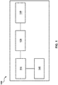
- FIG. 1 there is shown a computer system 100 suitable for use with some implementations of the present technology, the computer system 100 comprising various hardware components including one or more single or multi-core processors collectively represented by processor 110, a solid-state drive 120, a memory 130, which may be a random-access memory or any other type of memory.
- processor 110 one or more single or multi-core processors collectively represented by processor 110
- solid-state drive 120 a solid-state drive 120
- memory 130 which may be a random-access memory or any other type of memory.
- Communication between the various components of the computer system 100 may be enabled by one or more internal and/or external buses (not shown) (e.g. a PCI bus, universal serial bus, IEEE 1394 "Firewire” bus, SCSI bus, Serial-ATA bus, etc.), to which the various hardware components are electronically coupled.
- the solid-state drive 120 stores program instructions suitable for being loaded into the memory 130 and executed by the processor 110 for determining a presence of an object.
- the program instructions may be part of a vehicle control application executable by the processor 110.
- the computer system 100 may have additional and/or optional components (not depicted), such as network communication modules, locationalization modules, and the like.
- FIG. 2 illustrates a networked computer environment 200 suitable for use with some embodiments of the systems and/or methods of the present technology.
- the networked computer environment 200 comprises an electronic device 210 associated with a vehicle 220, and/or associated with a user (not depicted) who can operate the vehicle 220, a server 235 in communication with the electronic device 210 via a communication network 245 (e.g. the Internet or the like, as will be described in greater detail herein below).
- a communication network 245 e.g. the Internet or the like, as will be described in greater detail herein below.
- the networked computer environment 200 can also include a GPS satellite (not depicted) transmitting and/or receiving a GPS signal to/from the electronic device 210.
- a GPS satellite (not depicted) transmitting and/or receiving a GPS signal to/from the electronic device 210.
- the present technology is not limited to GPS and may employ a positioning technology other than GPS. It should be noted that the GPS satellite can be omitted altogether.
- the vehicle 220 to which the electronic device 210 is associated may comprise any leisure or transportation vehicle such as a private or commercial car, truck, motorbike or the like. Although the vehicle 220 is depicted as being a land vehicle, this may not be the case in each embodiment of the present technology.
- the vehicle 220 may be a watercraft, such as a boat, or an aircraft, such as a flying drone.
- the vehicle 220 may be user operated or a driver-less vehicle. It should be noted that specific parameters of the vehicle 220 are not limiting, these specific parameters including: vehicle manufacturer, vehicle model, vehicle year of manufacture, vehicle weight, vehicle dimensions, vehicle weight distribution, vehicle surface area, vehicle height, drive train type (e.g. 2x or 4x), tire type, brake system, fuel system, mileage, vehicle identification number, and engine size.
- the implementation of the electronic device 210 is not particularly limited, but as an example, the electronic device 210 may be implemented as a vehicle engine control unit, a vehicle CPU, a vehicle navigation device (e.g. TomTomTM, GarminTM), a tablet, a personal computer built into the vehicle 220 and the like. Thus, it should be noted that the electronic device 210 may or may not be permanently associated with the vehicle 220. Additionally or alternatively, the electronic device 210 can be implemented in a wireless communication device such as a mobile telephone (e.g. a smart-phone or a radio-phone). In certain embodiments, the electronic device 210 has a display 270.
- the electronic device 210 may comprise some or all of the components of the computer system 100 depicted in Figure 1 .
- the electronic device 210 is on-board computer device and comprises the processor 110, solid-state drive 120 and the memory 130.
- the electronic device 210 comprises hardware and/or software and/or firmware, or a combination thereof, for processing data as will be described in greater detail below.
- the electronic device 210 further comprises or has access to a sensor 230 configured to capture one or more digital images of at least a portion of a surrounding area 250 of the vehicle 220.
- the sensor 230 is communicatively coupled to the processor 110 for transmitting the so-captured information to the processor 110 for processing thereof, as will be described in greater detail herein below.
- the senor 230 comprises a camera.
- the camera is implemented is not particularly limited.
- the camera can be implemented as a mono camera with resolution sufficient to detect objects at a pre-determined distance of up to about 30 m (although cameras with other resolutions and ranges are within the scope of the present disclosure).
- the sensor 230 can be mounted on an interior, upper portion of a windshield of the vehicle 220, but other locations are within the scope of the present disclosure, including on a back window, side windows, front hood, rooftop, front grill, or front bumper of the vehicle 220. In some non-limiting embodiments of the present technology, the sensor 230 can be mounted in a dedicated enclosure (not depicted) mounted on the top of the vehicle 220.
- the senor 230 can be implemented as a plurality of cameras.
- the plurality of cameras may have a sufficient number of cameras to capture a surrounding / panoramic digital image of the surrounding area 250.
- the camera (or one or more cameras that make up the implementation of the sensor 230) may be configured to capture a pre-determined portion of the surrounding area 250 around the vehicle 220. In some embodiments of the present technology, the camera is configured to capture a digital image (or a series of digital images) that represent approximately 90 degrees of the surrounding area 250 around the vehicle 220 that are along a movement path of the vehicle 220.
- the camera is configured to capture a digital image (or a series of digital images) that represent approximately 180 degrees of the surrounding area 250 around the vehicle 220 that are along a movement path of the vehicle 220.
- the camera is configured to capture a digital image (or a series of digital images) that represent approximately 360 degrees of the surrounding area 250 around the vehicle 220 that are along a movement path of the vehicle 220 (in other words, the entirety of the surrounding area around the vehicle 220).
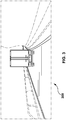
- a first digital image 300 captured by the sensor 230.
- the first digital image 300 represents a portion of the surrounding area 250 of the vehicle 220 at a first moment in time.
- the vehicle 220 is travelling on a road and that another vehicle (e.g., a truck) is in the surrounding area 250 of the vehicle 220.
- another vehicle e.g., a truck
- FIG. 5 there is depicted a second digital image 500 captured by the sensor 230.
- the second digital image 500 represents a portion of the surrounding area 250 of the vehicle 220 at a second moment in time that is after the first moment in time.
- the vehicle 220 is still travelling on the road and the another vehicle is still in the surrounding area 250 of the vehicle 220.
- first digital image 300 and the second digital image 500 may be part of a digital feed captured by the sensor 230.
- the sensor 230 may be capturing a digital feed (in a form of a sequence of digital images, for example).
- first digital image 300 may be representative of the digital feed of the sensor 230 at the first moment in time
- second digital image 500 may be representative of the digital feed of the sensor 230 at the second moment in time.
- the senor 230 implemented as the camera may be of the type available from FLIR Integrated Imaging Solutions Inc., 12051 Riverside Way, Richmond, BC, V6W 1K7, Canada. It should be expressly understood that the sensor 230 can be implemented in any other suitable equipment.
- sensors to the sensor 230 may be implemented in some embodiments of the present technology.
- radar systems may be mounted to the vehicle 220 and be communicatively coupled to the processor 110.
- LIDAR systems may be mounted to the vehicle 220 and be communicatively coupled to the processor 110.
- the vehicle 220 is depicted in Figure 2 for the sake of simplicity as having only the sensor 230, however in other embodiments, the vehicle 220 may be implemented with additional sensors to the sensor 230 without departing from the scope of the present technology.
- the senor 230 can be calibrated. This calibration can be executed during the manufacturing and/or set up of the vehicle 220. Or at any suitable time thereafter or, in other words, the calibration can be executed during retrofitting the vehicle 220 with the sensor 230 in accordance with the non-limiting embodiments of the present technology contemplated herein. Alternatively, the calibration can be executed during equipping the vehicle 220 with the sensor 230 in accordance with the non-limiting embodiments of the present technology contemplated herein.
- the communication network 245 is the Internet.
- the communication network can be implemented as any suitable local area network (LAN), wide area network (WAN), a private communication network or the like. It should be expressly understood that implementations for the communication network are for illustration purposes only.
- a communication link (not separately numbered) between the electronic device 210 and the communication network 245 is implemented will depend inter alia on how the electronic device 210 is implemented.
- the communication link can be implemented as a wireless communication link. Examples of wireless communication links include, but are not limited to, a 3G communication network link, a 4G communication network link, and the like.
- the communication network 245 may also use a wireless connection with the server 235.
- the server 235 is implemented as a conventional computer server and may comprise some or all of the components of the computer system 100 of Figure 1 .
- the server 235 is implemented as a DellTM PowerEdgeTM Server running the MicrosoftTM Windows ServerTM operating system, but can also be implemented in any other suitable hardware, software, and/or firmware, or a combination thereof.
- the server is a single server.
- the functionality of the server 235 may be distributed and may be implemented via multiple servers.
- the processor 110 of the electronic device 210 can be in communication with the server 235 to receive one or more updates.
- the updates can be, but are not limited to, software updates, map updates, routes updates, weather updates, and the like.
- the processor 110 can also be configured to transmit to the server 235 certain operational data, such as routes travelled, traffic data, performance data, and the like. Some or all data transmitted between the vehicle 220 and the server 235 may be encrypted and/or anonymized.
- the processor 110 is coupled to the sensor 230 for receiving image data therefrom.
- the processor 110 has access to a given Object Detecting Neural Network (ODNN).
- the given ODNN is a given Neural Network (NN) that is configured to perform object detection based on the image data being received from the sensor 230 (and potentially from other image data sources).
- NN Neural Network
- the processor 110 may be configured to receive image data representative of a given digital image from the sensor 230 and may employ the ODNN in order to (i) classify objects on the given digital image and (ii) localize the objects on the given digital image.
- the ODNN may be configured to classify objects on the given digital image into one or more object classes.
- Object classes may include, but are not limited to: “vehicle”, “car”, “truck”, “person”, “animal”, “tree”, “building”, “road”, “lane”, “road sign”, “wall”, “traffic light”, and the like.
- the ODNN may be configured to perform "one-class" type classification of objects. This means that the ODNN may be configured to determine whether or not a given object is of a particular object class. For example, the ODNN may be configured to determine whether or not the given object is of a "vehicle" class.
- the ODNN may be configured to perform "multi-class" type classification of objects. This means that the ODNN may be configured to determine which one of a plurality of object classes is to be associated with a given object. For example, the ODNN may be configured to determine which of "vehicle” class, "person” class, and "lane” class is to be associated with the given object.
- the ODNN may be configured to localize objects on the given digital image by determining a portion of the given digital image that corresponds to (or that is occupied by) the given object. For example, the ODNN may be configured to determine borders of the given object in the given digital image (and/or borders of an image portion of the given digital image that contains the given object). In another example, the ODNN may be configured to determine a zone which includes the given object in the given digital image.
- the ODNN may be configured to perform object detection - that is, classification and localization of objects on digital images - will now be described.
- the ODNN is a given NN.
- a given NN consists of a group of artificial interconnected "neurons", which process information using a connectionist approach to computation.
- NNs are used to model complex relationships between inputs and outputs (without actually knowing the relationships) or to find patterns in data.
- NNs are first conditioned in a training phase in which they are provided with a known set of "inputs" and information for adapting the NN to generate appropriate outputs (for a given situation that is being attempted to be modelled).
- the given NN adapts to the situation being learned and changes its structure such that the given NN will be able to provide reasonable predicted outputs for given inputs in a new situation (based on what was learned).
- the given NN tries to provide an "intuitive" answer based on a "feeling" for a situation.
- the given NN is thus a kind of a trained "black box", which can be used in a situation when what is in the "box” is unimportant; it is only important that the "box” provide reasonable answers to given inputs.
- NNs are commonly used in many such situations where it is only important to know an output based on a given input, but exactly how that output is derived is of lesser importance or is unimportant.
- NNs are commonly used to optimize the distribution of web-traffic between servers and in data processing, including filtering, clustering, signal separation, compression, vector generation, speech recognition, and the like.
- CNNs can be classified into a number of different classes of NNs which may have different topologies or architectures, properties and may be used in a variety of applications.
- One class of NNs include Convolutional NNs (CNNs).
- CNNs are multilayered NNs that are designed to have an input layer and an output layer, as well as a plurality of hidden layers that can include (depending on a specific implementation thereof) convolutional layers, pooling layers, fully-connected layers, and normalization layers, for example.
- CNNs can be used for analyzing visual imagery and other computer vision applications.
- the ODNN employed by the processor 110 for object detection purposes may be a given CNN, without departing from the scope of the present technology.
- the implementation of the ODNN by the processor 110 can be broadly categorized into two phases - a training phase and an in-use phase.
- the given ODNN is trained in the training phase.
- a large number of training iterations may be performed on the ODNN.
- the ODNN is inputted with (i) image data representative of a training digital image, and (ii) human-assessed data (e.g. a training human-assessed label) about objects on the training digital image (e.g., human-assessed object detection data).
- the human-assessed data may comprise indications of object classes of objects identified by human-assessors as well as indications of locations of objects identified by human-assessors.
- the given ODNN in a sense "learns" to identify objects, their classes and their locations on the training digital image based on image data representative of the training digital image. It is contemplated that the ODNN may be implemented and trained by at least one of the server 235 and/or by the processor 110 of the electronic device 210.
- the ODNN is actually run using in-use data.
- the ODNN is inputted with image data representative of an in-use digital image and, in response, outputs in-use object detection data indicative of (i) presence of objects on the in-use digital image, (ii) object classes of these objects, and (iii) locations of these objects in the in-use digital image.
- the first digital image 300 is representative of the digital feed of the sensor 230 at the first moment in time.
- the first digital image 300 may be a given digital image (associated with the first moment in time) in a sequence of digital images captured by the sensor 230 and transmitted to the processor 110 and/or to the server 235.
- the processor 110 may be configured to input image data representative of the first digital image 300 into the ODNN. In other words, the processor 110 may use the image data representative of the first digital image 300 as in-use data for the ODNN.
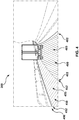
- the ODNN may output first in-use detection data 490 depicted in Figure 4 .
- the first in-use detection data 490 is indicative of that the ODNN detected a first object 400 and a second object 450.
- the ODNN may output the first in-use detection data 490 indicative of that (i) the first object 400 is present on the first digital image 300, (ii) the first object 400 is associated with the "lane" object class, and (iii) the first object 400 is located in the first digital image 300 within first boundaries 402.
- the ODNN is configured to detect the first object 400 on the first digital image 300 by determining a first portion 403 (e.g., a set of pixels) of the first digital image 300 that corresponds to the first object 400.
- a first portion 403 e.g., a set of pixels
- the first portion 403 is a given portion of the first digital image 300 that is bounded by the first boundaries 402.
- the ODNN may output the first in-use detection data 490 indicative of that (i) the second object 450 is present on the first digital image 300, (ii) the second object 450 is associated with the "lane" object class, and (iii) the second object 450 is located in the first digital image 300 within second boundaries 452.
- the ODNN is configured to detect the second object 450 on the first digital image 300 by determining another portion 453 (e.g., another set of pixels) of the first digital image 300 that corresponds to the second object 450.
- the another portion 453 is a given portion of the first digital image 300 that is bounded by the second boundaries 452.
- the ODNN detects the presence of two lanes on the road on which the vehicle 220 is travelling, where a most right lane of the road is the first object 400 and where a most left lane of the road is the second object 450.
- the ODNN may also be configured to detect additional objects on the first digital image 300 such as, for example, an object corresponding to the another vehicle (e.g., the truck).
- the ODNN detects the first object 400 and the second object 450 on the first digital image 300.
- the second digital image 500 is representative of the digital feed of the sensor 230 at the second moment in time.
- the second digital image 500 may be a given digital image (associated with the second moment in time) in a sequence of digital images captured by the sensor 230 and transmitted to the processor 110 and/or the server 235.
- the second moment in time is after the first moment in time associated with the first digital image 300.
- the time interval between the first moment in time and the second moment in time may be in the order of milliseconds.
- the digital feed of the sensor 230 may be in a video format and where two frames of the digital feed correspond to respective ones of the first digital image 300 and the second digital image 500.
- the first digital image 300 and the second digital image 500 may be sequential digital images from the digital feed of the sensor 230, but this does not need to be the case in each and every embodiment of the present technology.
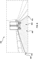
- the processor 110 and/or the server 235 may be configured to input image data representative of the second digital image 500 into the ODNN. In other words, the processor 110 and/or the server 235 may use the image data representative of the second digital image 500 as in-use data for the ODNN. In response, the ODNN may output second in-use detection data 690 depicted in Figure 6 . In this case, the second in-use detection data 690 is indicative of that the ODNN detected an altered first object 400', instead of detecting both the first object 400 and the second object 450.
- the ODNN may output the second in-use detection data 690 indicative of that (i) the altered first object 400' is present on the second digital image 500, (ii) the altered first object 400' is associated with the "lane" object class, and (iii) the altered first object 400' is located in the second digital image 500 within third boundaries 502.
- the ODNN is configured to detect the altered first object 400' on the second digital image 500 by determining a second portion 503 (e.g., a set of pixels) of the second digital image 500 that corresponds to the altered first object 400'.
- the second portion 503 is a given portion of the second digital image 500 that is bounded by the third boundaries 502.
- the ODNN detects based on the second digital image 500 the presence of one lane on the road, where this lane of the road is the altered first object 400', as opposed to detecting the presence of two lanes on the road based on the first digital image 300.
- both the altered first object 400' and the first object 400 detected by the ODNN correspond to a same actual object (e.g., a particular lane), however, the altered first object 400' and the first object 400 have been localized differently by the ODNN as part of their detection - that is, the ODNN has determined different portions (e.g., locations) of the respective digital images that correspond to this same actual object.
- the developers of the present technology have realized that having substantially different detections performed by the ODNN on two digital images having been captured in a short period of time from one another is problematic.
- the developers of the present technology have devised methods and systems for re-training the ODNN so that the ODNN detects objects in a more "consistent” manner, irrespective of the actual conditions of the surrounding area 250 of the vehicle 220 (see Figure 2 ).
- the actual condition of the road on which the vehicle 220 is travelling is that it has one, single lane.
- this single lane is a broad lane, such that it has a width that allows two vehicles to drive in it side-by-side (even if not per se allowed by law).
- detecting two lanes on the road (which is not the actual condition of the road but is rather the artificially-adjusted condition of the road) by the ODNN may allow the processor 110 to control the vehicle 220 differently and, in a sense, perform manoeuvers while "expecting" a potential overtake by a second vehicle even though the road has only one single lane.
- the developers of the present technology have devised solutions for selecting digital images that are to be used for re-training the ODNN so that it detects objects in in-use digital images in a consistent manner.
- the processor 110 and/or the server 235 may be configured to select at least one of the first digital image 300 and the second digital image 500, so as to be used for re-training the ODNN to perform more consistent object detection, by comparing (i) the first in-use detection data 490 associated with the first digital image 300 against (ii) the second in-use detection data 690 associated with the second digital image 500.
- the processor 110 and/or the server 235 may be configured to compare the first portion 403 of the first digital image 300 with the second portion 603 of the second digital image 500 to determine a detection similarity value for the first object 400 (and the altered first object 400').
- the detection similarity value is indicative of how similar predictions by the ODNN are in respect to detection of the same actual object (a particular lane of the road) at the first moment in time and at the second moment.
- the processor 110 and/or the server 235 may be configured to perform an Intersection Over Union (IOU) analysis on the first portion 403 and the second portion 603.
- IOU Intersection Over Union
- the IOU analysis (also known as the Jaccard Index and the Jaccard similarity coefficient) can gauge the similarity and diversity of sample sets. Broadly speaking, the IOU analysis results in a determination of a given IOU parameter indicative of a ratio between (i) an intersected area between the first portion 403 and the second portion 603 ( Figure 6 ), and (ii) a united area between the first portion 403 ( Figure 4 ) and the second portion 603.
- the detection similarity value determined by the processor 110 and/or the server 235 may be the IOU parameter for the first portion 403 and the second portion 603.
- the IOU analysis may be performed on projections of the first portion 403 and of the second portion 603 onto a two-dimensional surface, instead of performing the IOU analysis directly on the first portion 403 and the second portion 603.
- the processor 110 may be configured to: (i) project the first portion 403 onto a two-dimensional surface, (ii) project the second portion 603 onto a two-dimensional surface, and (iii) perform the IOU analysis on these projections of the first portion 403 and of the second portion 603, instead of performing the IOU analysis directly on the first portion 403 and the second portion 603.
- the processor 110 and/or the server 235 may be configured to compare this detection similarity value to a pre-determined threshold value.
- the pre-determined threshold value may be determined by an operator of the processor 110 and/or the server 235. For example, the operator of the processor 110 and/or the server 235 may empirically determine the pre-determined threshold value.
- the processor 110 may be configured to use at least one of the first digital image 300 and the second digital image 500 for re-training the ODNN.
- the first digital image 300 may be provided to human-assessors tasked with identifying and locating objects of the first digital image 300. For example, they may be tasked with identifying human-assessed locations of objects on the first digital image 300 as well as their respective object classes (e.g., generating a human-assessed label for the first digital image 300). In some cases, they may be tasked to identify locations of objects in accordance with actual conditions of the road. In other cases however, as explained above, they may be tasked to identify locations of objects in accordance with artificially-adjusted conditions of the road.
- human-assessors tasked with identifying and locating objects of the first digital image 300. For example, they may be tasked with identifying human-assessed locations of objects on the first digital image 300 as well as their respective object classes (e.g., generating a human-assessed label for the first digital image 300). In some cases, they may be tasked to identify locations of objects in accordance with actual conditions
- the processor 110 and/or the server 235 may perform re-training of the ODNN based on the selected at least one of the first digital image 300 and the second digital image 500 and the respective human-assessed data. For example, a second training-phase of the ODNN may be performed by the processor 110 and/or the server 235 based on the at least one of the first digital image 300 and the second digital image 500 and the respective human-assessed data so as to condition the ODNN to perform in-use object detection in a more consistent manner.
- a method 700 of generating training data for re-training the ODNN and which is executable by a computer device such as, for example, the processor 110 and/or the server 235.
- the method 700 will now be described in greater detail.
- STEP 702 inputting a first digital image into the ODNN
- the method 700 begins at step 702 with a computer device communicatively coupled with the ODNN (such as for example, the processor 110 and/or the server 235) inputting the first digital image 300 into the ODNN.
- the first digital image 300 is representative of the digital feed of the sensor 230 at the first moment in time.
- the ODNN is configured to detect a given object (e.g., the first object 400 depicted in Figure 4 ) on the first digital image 300 by determining the first portion 403 of the first digital image 300 that corresponds to the given object.
- a given object e.g., the first object 400 depicted in Figure 4
- the ODNN may have been trained during its training phase.
- the ODNN may have been trained (prior to the step 702) for object detection based on (i) a training digital image and (ii) a human-assessed label about objects on the training digital image, and such that the ODNN predicts classes of objects and locations of objects on the training digital image.
- STEP 704 inputting a second digital image into the ODNN
- the method 700 continues to step 704 with the computer device inputting the second digital image 500 into the ODNN.
- the second digital image 500 is representative of the digital feed of the sensor 230 at the second moment in time after the first moment in time.
- the ODNN is configured to detect the given object (e.g., the altered first object 400') on the second digital image 500 by determining the second portion 603 of the second digital image 500 that corresponds to the given object.
- the given object e.g., the altered first object 400'
- both the altered first object 400' and the first object 400 detected by the ODNN correspond to a same actual object (e.g., a particular lane), however, the altered first object 400' and the first object 400 have been localized differently by the ODNN as part of their detection - that is, the ODNN determines different portions (e.g., locations) of the respective digital images that correspond to this same actual object.
- STEP 706 comparing the first portion of the first digital image with the second portion of the second digital image to determine a detection similarity value for the given object
- the method 700 continues to step 706 with the computer device comparing the first portion 403 of the first digital image 300 with the second portion 603 of the second digital image 500 to determine the detection similarity value for the given object.
- the detection similarity value is indicative of how similar predictions executed by the ODNN at the first moment in time and the second moment in time in respect to detection of the given object are. It can also be said that the detection similarity value is indicative of how similar the predictions of the ODNN regarding the locations of the given object on the respective digital images are to one another.
- the comparing the first portion 403 of the first digital image 300 with the second portion 603 of the second digital image 500 to determine the detection similarity value may comprise applying by the computer device an Intersection Over Union (IOU) analysis. It is contemplated that applying the IOU analysis, as alluded to above, may comprise (i) determining the intersection of between first portion 403 and the second portion 603, and (ii) determining a union of the first portion 403 with the second portion 603.
- IOU Intersection Over Union
- the method 700 continues to step 708 with the computer device, in response to the detection similarity value being below the pre-determined threshold value, using at least one of the first digital image 300 and the second digital image 500 for obtaining the respective human-assessed label indicative of the actual portion of the at least one of the first digital image 300 and the second digital image 500 that is occupied by the given object in the respective one of the first digital image 300 and the second digital image 500.
- the actual portion occupied by the given object may be identified by a human-assessor based on the actual condition of the given object as explained above. In other embodiments, the actual portion of the given object may be identified by a human-assessor based on the artificially-adjusted condition of the given object as explained above.
- the method 700 continues to step 710 with the computer device re-training the ODNN based on the at least one of the first digital image 300 and the second digital image 500 and the respective human-assessed label(s).
- the first digital image 300 may be used with its respective human-assessed label in order to re-train the ODNN.
- the second digital image 500 may be used with its respective human-assessed label in order to re-train the ODNN.
- both the first digital image 300 with its respective human-assessed label and the second digital image 500 with its respective human-assessed label may be used in order to re-train the ODNN.
- the actual portion of the given object on a given digital image identified by the human-assessor may depend on whether the human-assessor is tasked with identifying the actual condition of the given object or with identifying the artificially-adjusted condition of the given object. As such, if the human-assessor is tasked with identifying the actual portion of the given object in accordance with the actual condition of the given object, the ODNN may be re-trained so as to detect objects in accordance with actual conditions of objects.
- the ODNN may be re-trained so as to detect objects in accordance with artificially-adjusted conditions of objects.
- the above steps of the method 700 may be repeated for a third digital image (not depicted) from the digital feed of the sensor 230 and for a fourth digital image (not depicted) from the digital feed of the sensor 230, similarly to how the computer device is configured to perform the above steps for the first digital image 300 and the second digital image 500, without departing from the scope of the present technology.
- the computer device may be configured to generate a re-training dataset for the ODNN.
- the re-training dataset may comprise any combination of (i) the first digital image 300 with its respective human-assessed label, (ii) the second digital image 500 with its respective human-assessed label, (iii) the third digital image with its respective human-assessed label, and (iv) the fourth digital image with its respective human-assessed label.
- the computer device may determine that the surrounding area 250 of the vehicle 220 at the first moment in time and/or at the second moment in time is an inconsistent-detection area.
- the vehicle 220 may include a GPS-type sensor, for example, which may provide positioning data indicative of the location of the surrounding area 250 at a given moment in time.
- the computer device may determine that the surrounding area 250 of the vehicle 220 at the moment in time when the at least one of the first digital image 300 and the second digital image 500 has been captured is an inconsistent-detection area.
- the computer device may mark and track inconsistent-detection areas for further analysis.
- the re-training dataset generated for the ODNN may be used by the computer device (which may be the processor 110 of the electronic device 210, or the processor 110 of the server 235, for example) to re-train the ODNN on features of digital images for which the ODNN performs inconsistent detection of objects.
- the computer device which may be the processor 110 of the electronic device 210, or the processor 110 of the server 235, for example
- the computer device which may be the processor 110 of the electronic device 210, or the processor 110 of the server 235, for example
- the ODNN performs detection of a given object based on similar inputs.
- the inputs are similar (e.g., image data of the first digital image 300 and the second digital image 500)
- the outputs of the ODNN may be substantially different.
- (i) generating the re-training dataset based on, in a sense, situations where similar inputs of the ODNN resulted in substantially different outputs of the ODNN, and (ii) using this re-training dataset to re-train the ODNN may reduce a likelihood of the ODNN performing inconsistent detection of objects after its re-training phase.
- the computer device may re-train the ODNN on features of the first digital image 300 and/or the second digital image 500 (the features derivable by the ODNN based on the respective image data), so that, after the re-training phase, the ODNN is less likely to perform an inconsistent detection of objects when receiving inputs similar to the image data of the first digital image 300 and/or the second digital image 500.
- re-training the ODNN may be performed by the computer device so that the ODNN is less likely to perform inconsistent object detection when the vehicle 220 (or other potential vehicles implemented similarly to the vehicle 220) is in the inconsistent-detection area.
- the ODNN may be less likely to repeat inconsistent object detection - that is, although the ODNN may perform inconsistent object detection based on image data of digital images captured in the inconsistent-detection area before the re-training phase, after the re-training phase, the ODNN is comparatively less likely to perform inconsistent object detection based on image data of digital images captured in the inconsistent-detection area.
- the re-training of the ODNN may be performed so that the ODNN is less likely to perform inconsistent object detection based on features of digital images captured in the inconsistent-detection area. Additionally, it is contemplated that re-training of the ODNN may be performed so that the ODNN is less likely to perform inconsistent object detection based on features of digital images captured in areas that are similar to the inconsistent-detection area. For example, digital images of areas that are similar to the inconsistent-detection area may be associated with features that are similar to features of digital images of the inconsistent-detection area.
Landscapes
- Engineering & Computer Science (AREA)
- Theoretical Computer Science (AREA)
- Physics & Mathematics (AREA)
- General Physics & Mathematics (AREA)
- Evolutionary Computation (AREA)
- Artificial Intelligence (AREA)
- Computer Vision & Pattern Recognition (AREA)
- Multimedia (AREA)
- Data Mining & Analysis (AREA)
- Software Systems (AREA)
- General Health & Medical Sciences (AREA)
- Health & Medical Sciences (AREA)
- Computing Systems (AREA)
- Medical Informatics (AREA)
- Databases & Information Systems (AREA)
- Life Sciences & Earth Sciences (AREA)
- General Engineering & Computer Science (AREA)
- Bioinformatics & Computational Biology (AREA)
- Evolutionary Biology (AREA)
- Bioinformatics & Cheminformatics (AREA)
- Biomedical Technology (AREA)
- Biophysics (AREA)
- Computational Linguistics (AREA)
- Molecular Biology (AREA)
- Mathematical Physics (AREA)
- Image Analysis (AREA)
Applications Claiming Priority (1)
| Application Number | Priority Date | Filing Date | Title |
|---|---|---|---|
| RU2018146459 | 2018-12-26 |
Publications (2)
| Publication Number | Publication Date |
|---|---|
| EP3674972A1 true EP3674972A1 (fr) | 2020-07-01 |
| EP3674972B1 EP3674972B1 (fr) | 2021-09-08 |
Family
ID=68583270
Family Applications (1)
| Application Number | Title | Priority Date | Filing Date |
|---|---|---|---|
| EP19209570.1A Active EP3674972B1 (fr) | 2018-12-26 | 2019-11-15 | Procédés et systèmes pour générer des données d'entrainement pour un réseau neuronal |
Country Status (3)
| Country | Link |
|---|---|
| US (1) | US20200210778A1 (fr) |
| EP (1) | EP3674972B1 (fr) |
| IL (1) | IL270519A (fr) |
Families Citing this family (3)
| Publication number | Priority date | Publication date | Assignee | Title |
|---|---|---|---|---|
| EP4047515B1 (fr) * | 2021-02-19 | 2023-10-11 | Zenseact AB | Plateforme de développement de système de perception pour des systèmes de conduite automatisée |
| EP4047514B1 (fr) | 2021-02-19 | 2023-10-11 | Zenseact AB | Plateforme de développement de système de perception pour système de conduite automatisée |
| US20230084623A1 (en) * | 2021-09-10 | 2023-03-16 | Argo AI, LLC | Attentional sampling for long range detection in autonomous vehicles |
-
2019
- 2019-09-09 US US16/564,133 patent/US20200210778A1/en not_active Abandoned
- 2019-11-07 IL IL270519A patent/IL270519A/en unknown
- 2019-11-15 EP EP19209570.1A patent/EP3674972B1/fr active Active
Non-Patent Citations (5)
| Title |
|---|
| ALJO\V{S}A O\V{S}EP ET AL: "Large-Scale Object Discovery and Detector Adaptation from Unlabeled Video", ARXIV.ORG, CORNELL UNIVERSITY LIBRARY, 201 OLIN LIBRARY CORNELL UNIVERSITY ITHACA, NY 14853, 23 December 2017 (2017-12-23), XP080848275 * |
| KAO CHIEH-CHI ET AL: "Localization-Aware Active Learning for Object Detection", 16 January 2018, ROBOCUP 2008: ROBOCUP 2008: ROBOT SOCCER WORLD CUP XII; [LECTURE NOTES IN COMPUTER SCIENCE; LECT.NOTES COMPUTER], SPRINGER INTERNATIONAL PUBLISHING, CHAM, PAGE(S) 506 - 522, ISBN: 978-3-319-10403-4, XP047508320 * |
| LAMPERT CHRISTOPH H ET AL: "Active Structured Learning for High-Speed Object Detection", 9 September 2009, INTERNATIONAL CONFERENCE ON FINANCIAL CRYPTOGRAPHY AND DATA SECURITY; [LECTURE NOTES IN COMPUTER SCIENCE; LECT.NOTES COMPUTER], SPRINGER, BERLIN, HEIDELBERG, PAGE(S) 221 - 231, ISBN: 978-3-642-17318-9, XP047380382 * |
| SAYANAN SIVARAMAN ET AL: "A General Active-Learning Framework for On-Road Vehicle Recognition and Tracking", IEEE TRANSACTIONS ON INTELLIGENT TRANSPORTATION SYSTEMS, IEEE, PISCATAWAY, NJ, USA, vol. 11, no. 2, 1 June 2010 (2010-06-01), pages 267 - 276, XP011347242, ISSN: 1524-9050, DOI: 10.1109/TITS.2010.2040177 * |
| ZOLFAGHARI BENGAR JAVAD ET AL: "Temporal Coherence for Active Learning in Videos", 2019 IEEE/CVF INTERNATIONAL CONFERENCE ON COMPUTER VISION WORKSHOP (ICCVW), IEEE, 27 October 2019 (2019-10-27), pages 914 - 923, XP033732867, DOI: 10.1109/ICCVW.2019.00120 * |
Also Published As
| Publication number | Publication date |
|---|---|
| US20200210778A1 (en) | 2020-07-02 |
| EP3674972B1 (fr) | 2021-09-08 |
| IL270519A (en) | 2020-06-30 |
Similar Documents
| Publication | Publication Date | Title |
|---|---|---|
| US11433902B2 (en) | Methods and systems for computer-based determining of presence of dynamic objects | |
| US11163990B2 (en) | Vehicle control system and method for pedestrian detection based on head detection in sensor data | |
| US11164016B2 (en) | Object detection and property determination for autonomous vehicles | |
| WO2020264010A1 (fr) | Détection de région à faible variance pour une détection améliorée | |
| US11551365B2 (en) | Methods and systems for computer-based determining of presence of objects | |
| EP3674972B1 (fr) | Procédés et systèmes pour générer des données d'entrainement pour un réseau neuronal | |
| CN114072841A (zh) | 根据图像使深度精准化 | |
| US11574483B2 (en) | Methods and systems for computer-based determining of presence of objects | |
| US11740358B2 (en) | Methods and systems for computer-based determining of presence of objects | |
| RU2750243C2 (ru) | Способ и система для формирования траектории для беспилотного автомобиля (sdc) | |
| CN114061581A (zh) | 通过相互重要性对自动驾驶车辆附近的智能体排名 | |
| EP4064127A1 (fr) | Procédés et dispositifs électroniques pour détecter des objets dans l'environnement d'une voiture autonome | |
| US11760384B2 (en) | Methods and systems for determining trajectory estimation order for vehicles | |
| RU2763215C2 (ru) | Способы и системы формирования обучающих данных для нейронной сети | |
| EP4095009A1 (fr) | Procédé et dispositif de fonctionnement de voiture autonome | |
| US20230368541A1 (en) | Object attention network | |
| US20220388531A1 (en) | Method and device for operating a self-driving car | |
| US20220379911A1 (en) | Using relevance of objects to assess performance of an autonomous vehicle perception system | |
| US20230410469A1 (en) | Systems and methods for image classification using a neural network combined with a correlation structure | |
| US20220382284A1 (en) | Perception system for assessing relevance of objects in an environment of an autonomous vehicle | |
| WO2022251769A1 (fr) | Utilisation de la pertinence d'objets pour évaluer les performances d'un système de perception de véhicule autonome |
Legal Events
| Date | Code | Title | Description |
|---|---|---|---|
| PUAI | Public reference made under article 153(3) epc to a published international application that has entered the european phase |
Free format text: ORIGINAL CODE: 0009012 |
|
| STAA | Information on the status of an ep patent application or granted ep patent |
Free format text: STATUS: EXAMINATION IS IN PROGRESS |
|
| 17P | Request for examination filed |
Effective date: 20191115 |
|
| AK | Designated contracting states |
Kind code of ref document: A1 Designated state(s): AL AT BE BG CH CY CZ DE DK EE ES FI FR GB GR HR HU IE IS IT LI LT LU LV MC MK MT NL NO PL PT RO RS SE SI SK SM TR |
|
| AX | Request for extension of the european patent |
Extension state: BA ME |
|
| RAP1 | Party data changed (applicant data changed or rights of an application transferred) |
Owner name: YANDEX SELF DRIVING GROUP LLC |
|
| STAA | Information on the status of an ep patent application or granted ep patent |
Free format text: STATUS: EXAMINATION IS IN PROGRESS |
|
| GRAP | Despatch of communication of intention to grant a patent |
Free format text: ORIGINAL CODE: EPIDOSNIGR1 |
|
| STAA | Information on the status of an ep patent application or granted ep patent |
Free format text: STATUS: GRANT OF PATENT IS INTENDED |
|
| INTG | Intention to grant announced |
Effective date: 20210331 |
|
| GRAS | Grant fee paid |
Free format text: ORIGINAL CODE: EPIDOSNIGR3 |
|
| GRAA | (expected) grant |
Free format text: ORIGINAL CODE: 0009210 |
|
| STAA | Information on the status of an ep patent application or granted ep patent |
Free format text: STATUS: THE PATENT HAS BEEN GRANTED |
|
| AK | Designated contracting states |
Kind code of ref document: B1 Designated state(s): AL AT BE BG CH CY CZ DE DK EE ES FI FR GB GR HR HU IE IS IT LI LT LU LV MC MK MT NL NO PL PT RO RS SE SI SK SM TR |
|
| REG | Reference to a national code |
Ref country code: GB Ref legal event code: FG4D |
|
| REG | Reference to a national code |
Ref country code: CH Ref legal event code: EP Ref country code: AT Ref legal event code: REF Ref document number: 1429261 Country of ref document: AT Kind code of ref document: T Effective date: 20210915 |
|
| REG | Reference to a national code |
Ref country code: IE Ref legal event code: FG4D |
|
| REG | Reference to a national code |
Ref country code: DE Ref legal event code: R096 Ref document number: 602019007539 Country of ref document: DE |
|
| REG | Reference to a national code |
Ref country code: DE Ref legal event code: R079 Ref document number: 602019007539 Country of ref document: DE Free format text: PREVIOUS MAIN CLASS: G06K0009000000 Ipc: G06V0010000000 |
|
| REG | Reference to a national code |
Ref country code: LT Ref legal event code: MG9D |
|
| REG | Reference to a national code |
Ref country code: NL Ref legal event code: MP Effective date: 20210908 |
|
| PG25 | Lapsed in a contracting state [announced via postgrant information from national office to epo] |
Ref country code: SE Free format text: LAPSE BECAUSE OF FAILURE TO SUBMIT A TRANSLATION OF THE DESCRIPTION OR TO PAY THE FEE WITHIN THE PRESCRIBED TIME-LIMIT Effective date: 20210908 Ref country code: RS Free format text: LAPSE BECAUSE OF FAILURE TO SUBMIT A TRANSLATION OF THE DESCRIPTION OR TO PAY THE FEE WITHIN THE PRESCRIBED TIME-LIMIT Effective date: 20210908 Ref country code: ES Free format text: LAPSE BECAUSE OF FAILURE TO SUBMIT A TRANSLATION OF THE DESCRIPTION OR TO PAY THE FEE WITHIN THE PRESCRIBED TIME-LIMIT Effective date: 20210908 Ref country code: BG Free format text: LAPSE BECAUSE OF FAILURE TO SUBMIT A TRANSLATION OF THE DESCRIPTION OR TO PAY THE FEE WITHIN THE PRESCRIBED TIME-LIMIT Effective date: 20211208 Ref country code: LT Free format text: LAPSE BECAUSE OF FAILURE TO SUBMIT A TRANSLATION OF THE DESCRIPTION OR TO PAY THE FEE WITHIN THE PRESCRIBED TIME-LIMIT Effective date: 20210908 Ref country code: FI Free format text: LAPSE BECAUSE OF FAILURE TO SUBMIT A TRANSLATION OF THE DESCRIPTION OR TO PAY THE FEE WITHIN THE PRESCRIBED TIME-LIMIT Effective date: 20210908 Ref country code: HR Free format text: LAPSE BECAUSE OF FAILURE TO SUBMIT A TRANSLATION OF THE DESCRIPTION OR TO PAY THE FEE WITHIN THE PRESCRIBED TIME-LIMIT Effective date: 20210908 Ref country code: NO Free format text: LAPSE BECAUSE OF FAILURE TO SUBMIT A TRANSLATION OF THE DESCRIPTION OR TO PAY THE FEE WITHIN THE PRESCRIBED TIME-LIMIT Effective date: 20211208 |
|
| REG | Reference to a national code |
Ref country code: AT Ref legal event code: MK05 Ref document number: 1429261 Country of ref document: AT Kind code of ref document: T Effective date: 20210908 |
|
| PG25 | Lapsed in a contracting state [announced via postgrant information from national office to epo] |
Ref country code: LV Free format text: LAPSE BECAUSE OF FAILURE TO SUBMIT A TRANSLATION OF THE DESCRIPTION OR TO PAY THE FEE WITHIN THE PRESCRIBED TIME-LIMIT Effective date: 20210908 Ref country code: GR Free format text: LAPSE BECAUSE OF FAILURE TO SUBMIT A TRANSLATION OF THE DESCRIPTION OR TO PAY THE FEE WITHIN THE PRESCRIBED TIME-LIMIT Effective date: 20211209 |
|
| PG25 | Lapsed in a contracting state [announced via postgrant information from national office to epo] |
Ref country code: AT Free format text: LAPSE BECAUSE OF FAILURE TO SUBMIT A TRANSLATION OF THE DESCRIPTION OR TO PAY THE FEE WITHIN THE PRESCRIBED TIME-LIMIT Effective date: 20210908 |
|
| PG25 | Lapsed in a contracting state [announced via postgrant information from national office to epo] |
Ref country code: IS Free format text: LAPSE BECAUSE OF FAILURE TO SUBMIT A TRANSLATION OF THE DESCRIPTION OR TO PAY THE FEE WITHIN THE PRESCRIBED TIME-LIMIT Effective date: 20220108 Ref country code: SM Free format text: LAPSE BECAUSE OF FAILURE TO SUBMIT A TRANSLATION OF THE DESCRIPTION OR TO PAY THE FEE WITHIN THE PRESCRIBED TIME-LIMIT Effective date: 20210908 Ref country code: SK Free format text: LAPSE BECAUSE OF FAILURE TO SUBMIT A TRANSLATION OF THE DESCRIPTION OR TO PAY THE FEE WITHIN THE PRESCRIBED TIME-LIMIT Effective date: 20210908 Ref country code: RO Free format text: LAPSE BECAUSE OF FAILURE TO SUBMIT A TRANSLATION OF THE DESCRIPTION OR TO PAY THE FEE WITHIN THE PRESCRIBED TIME-LIMIT Effective date: 20210908 Ref country code: PT Free format text: LAPSE BECAUSE OF FAILURE TO SUBMIT A TRANSLATION OF THE DESCRIPTION OR TO PAY THE FEE WITHIN THE PRESCRIBED TIME-LIMIT Effective date: 20220110 Ref country code: PL Free format text: LAPSE BECAUSE OF FAILURE TO SUBMIT A TRANSLATION OF THE DESCRIPTION OR TO PAY THE FEE WITHIN THE PRESCRIBED TIME-LIMIT Effective date: 20210908 Ref country code: NL Free format text: LAPSE BECAUSE OF FAILURE TO SUBMIT A TRANSLATION OF THE DESCRIPTION OR TO PAY THE FEE WITHIN THE PRESCRIBED TIME-LIMIT Effective date: 20210908 Ref country code: EE Free format text: LAPSE BECAUSE OF FAILURE TO SUBMIT A TRANSLATION OF THE DESCRIPTION OR TO PAY THE FEE WITHIN THE PRESCRIBED TIME-LIMIT Effective date: 20210908 Ref country code: CZ Free format text: LAPSE BECAUSE OF FAILURE TO SUBMIT A TRANSLATION OF THE DESCRIPTION OR TO PAY THE FEE WITHIN THE PRESCRIBED TIME-LIMIT Effective date: 20210908 Ref country code: AL Free format text: LAPSE BECAUSE OF FAILURE TO SUBMIT A TRANSLATION OF THE DESCRIPTION OR TO PAY THE FEE WITHIN THE PRESCRIBED TIME-LIMIT Effective date: 20210908 |
|
| REG | Reference to a national code |
Ref country code: DE Ref legal event code: R097 Ref document number: 602019007539 Country of ref document: DE |
|
| PG25 | Lapsed in a contracting state [announced via postgrant information from national office to epo] |
Ref country code: MC Free format text: LAPSE BECAUSE OF FAILURE TO SUBMIT A TRANSLATION OF THE DESCRIPTION OR TO PAY THE FEE WITHIN THE PRESCRIBED TIME-LIMIT Effective date: 20210908 |
|
| PLBE | No opposition filed within time limit |
Free format text: ORIGINAL CODE: 0009261 |
|
| STAA | Information on the status of an ep patent application or granted ep patent |
Free format text: STATUS: NO OPPOSITION FILED WITHIN TIME LIMIT |
|
| PG25 | Lapsed in a contracting state [announced via postgrant information from national office to epo] |
Ref country code: LU Free format text: LAPSE BECAUSE OF NON-PAYMENT OF DUE FEES Effective date: 20211115 Ref country code: DK Free format text: LAPSE BECAUSE OF FAILURE TO SUBMIT A TRANSLATION OF THE DESCRIPTION OR TO PAY THE FEE WITHIN THE PRESCRIBED TIME-LIMIT Effective date: 20210908 Ref country code: BE Free format text: LAPSE BECAUSE OF NON-PAYMENT OF DUE FEES Effective date: 20211130 |
|
| REG | Reference to a national code |
Ref country code: BE Ref legal event code: MM Effective date: 20211130 |
|
| 26N | No opposition filed |
Effective date: 20220609 |
|
| PG25 | Lapsed in a contracting state [announced via postgrant information from national office to epo] |
Ref country code: SI Free format text: LAPSE BECAUSE OF FAILURE TO SUBMIT A TRANSLATION OF THE DESCRIPTION OR TO PAY THE FEE WITHIN THE PRESCRIBED TIME-LIMIT Effective date: 20210908 |
|
| PG25 | Lapsed in a contracting state [announced via postgrant information from national office to epo] |
Ref country code: IE Free format text: LAPSE BECAUSE OF NON-PAYMENT OF DUE FEES Effective date: 20211115 |
|
| PG25 | Lapsed in a contracting state [announced via postgrant information from national office to epo] |
Ref country code: IT Free format text: LAPSE BECAUSE OF FAILURE TO SUBMIT A TRANSLATION OF THE DESCRIPTION OR TO PAY THE FEE WITHIN THE PRESCRIBED TIME-LIMIT Effective date: 20210908 |
|
| P01 | Opt-out of the competence of the unified patent court (upc) registered |
Effective date: 20230521 |
|
| PG25 | Lapsed in a contracting state [announced via postgrant information from national office to epo] |
Ref country code: CY Free format text: LAPSE BECAUSE OF FAILURE TO SUBMIT A TRANSLATION OF THE DESCRIPTION OR TO PAY THE FEE WITHIN THE PRESCRIBED TIME-LIMIT Effective date: 20210908 |
|
| REG | Reference to a national code |
Ref country code: CH Ref legal event code: PL |
|
| PG25 | Lapsed in a contracting state [announced via postgrant information from national office to epo] |
Ref country code: LI Free format text: LAPSE BECAUSE OF NON-PAYMENT OF DUE FEES Effective date: 20221130 Ref country code: HU Free format text: LAPSE BECAUSE OF FAILURE TO SUBMIT A TRANSLATION OF THE DESCRIPTION OR TO PAY THE FEE WITHIN THE PRESCRIBED TIME-LIMIT; INVALID AB INITIO Effective date: 20191115 Ref country code: CH Free format text: LAPSE BECAUSE OF NON-PAYMENT OF DUE FEES Effective date: 20221130 |
|
| REG | Reference to a national code |
Ref country code: DE Ref legal event code: R081 Ref document number: 602019007539 Country of ref document: DE Owner name: DIRECT CURSUS TECHNOLOGY L.L.C., AE Free format text: FORMER OWNER: YANDEX SELF DRIVING GROUP LLC, MOSCOW, RU |
|
| REG | Reference to a national code |
Ref country code: GB Ref legal event code: 732E Free format text: REGISTERED BETWEEN 20231214 AND 20231220 |
|
| PGFP | Annual fee paid to national office [announced via postgrant information from national office to epo] |
Ref country code: GB Payment date: 20231222 Year of fee payment: 5 |
|
| PGFP | Annual fee paid to national office [announced via postgrant information from national office to epo] |
Ref country code: FR Payment date: 20231109 Year of fee payment: 5 Ref country code: DE Payment date: 20231108 Year of fee payment: 5 |
|
| PG25 | Lapsed in a contracting state [announced via postgrant information from national office to epo] |
Ref country code: MK Free format text: LAPSE BECAUSE OF FAILURE TO SUBMIT A TRANSLATION OF THE DESCRIPTION OR TO PAY THE FEE WITHIN THE PRESCRIBED TIME-LIMIT Effective date: 20210908 |