EP3674886B1 - Funktionsblockrahmenerzeugung - Google Patents
Funktionsblockrahmenerzeugung Download PDFInfo
- Publication number
- EP3674886B1 EP3674886B1 EP19218955.3A EP19218955A EP3674886B1 EP 3674886 B1 EP3674886 B1 EP 3674886B1 EP 19218955 A EP19218955 A EP 19218955A EP 3674886 B1 EP3674886 B1 EP 3674886B1
- Authority
- EP
- European Patent Office
- Prior art keywords
- function block
- framework
- input
- core
- function
- Prior art date
- Legal status (The legal status is an assumption and is not a legal conclusion. Google has not performed a legal analysis and makes no representation as to the accuracy of the status listed.)
- Active
Links
Images







Classifications
-
- G—PHYSICS
- G06—COMPUTING OR CALCULATING; COUNTING
- G06F—ELECTRIC DIGITAL DATA PROCESSING
- G06F8/00—Arrangements for software engineering
- G06F8/30—Creation or generation of source code
- G06F8/36—Software reuse
-
- G—PHYSICS
- G06—COMPUTING OR CALCULATING; COUNTING
- G06F—ELECTRIC DIGITAL DATA PROCESSING
- G06F8/00—Arrangements for software engineering
- G06F8/30—Creation or generation of source code
- G06F8/34—Graphical or visual programming
-
- G—PHYSICS
- G06—COMPUTING OR CALCULATING; COUNTING
- G06F—ELECTRIC DIGITAL DATA PROCESSING
- G06F8/00—Arrangements for software engineering
- G06F8/20—Software design
-
- G—PHYSICS
- G06—COMPUTING OR CALCULATING; COUNTING
- G06F—ELECTRIC DIGITAL DATA PROCESSING
- G06F11/00—Error detection; Error correction; Monitoring
- G06F11/36—Prevention of errors by analysis, debugging or testing of software
- G06F11/3604—Analysis of software for verifying properties of programs
- G06F11/3608—Analysis of software for verifying properties of programs using formal methods, e.g. model checking, abstract interpretation
-
- G—PHYSICS
- G06—COMPUTING OR CALCULATING; COUNTING
- G06F—ELECTRIC DIGITAL DATA PROCESSING
- G06F11/00—Error detection; Error correction; Monitoring
- G06F11/36—Prevention of errors by analysis, debugging or testing of software
- G06F11/3668—Testing of software
- G06F11/3672—Test management
-
- G—PHYSICS
- G06—COMPUTING OR CALCULATING; COUNTING
- G06F—ELECTRIC DIGITAL DATA PROCESSING
- G06F8/00—Arrangements for software engineering
- G06F8/20—Software design
- G06F8/24—Object-oriented
-
- G—PHYSICS
- G06—COMPUTING OR CALCULATING; COUNTING
- G06F—ELECTRIC DIGITAL DATA PROCESSING
- G06F8/00—Arrangements for software engineering
- G06F8/30—Creation or generation of source code
- G06F8/31—Programming languages or programming paradigms
- G06F8/311—Functional or applicative languages; Rewrite languages
-
- G—PHYSICS
- G06—COMPUTING OR CALCULATING; COUNTING
- G06F—ELECTRIC DIGITAL DATA PROCESSING
- G06F8/00—Arrangements for software engineering
- G06F8/40—Transformation of program code
- G06F8/41—Compilation
-
- G—PHYSICS
- G06—COMPUTING OR CALCULATING; COUNTING
- G06F—ELECTRIC DIGITAL DATA PROCESSING
- G06F8/00—Arrangements for software engineering
- G06F8/70—Software maintenance or management
-
- G—PHYSICS
- G06—COMPUTING OR CALCULATING; COUNTING
- G06F—ELECTRIC DIGITAL DATA PROCESSING
- G06F9/00—Arrangements for program control, e.g. control units
- G06F9/06—Arrangements for program control, e.g. control units using stored programs, i.e. using an internal store of processing equipment to receive or retain programs
- G06F9/44—Arrangements for executing specific programs
- G06F9/445—Program loading or initiating
- G06F9/44505—Configuring for program initiating, e.g. using registry, configuration files
-
- G—PHYSICS
- G06—COMPUTING OR CALCULATING; COUNTING
- G06F—ELECTRIC DIGITAL DATA PROCESSING
- G06F9/00—Arrangements for program control, e.g. control units
- G06F9/06—Arrangements for program control, e.g. control units using stored programs, i.e. using an internal store of processing equipment to receive or retain programs
- G06F9/44—Arrangements for executing specific programs
- G06F9/445—Program loading or initiating
- G06F9/44536—Selecting among different versions
- G06F9/44542—Retargetable
-
- G—PHYSICS
- G06—COMPUTING OR CALCULATING; COUNTING
- G06F—ELECTRIC DIGITAL DATA PROCESSING
- G06F9/00—Arrangements for program control, e.g. control units
- G06F9/06—Arrangements for program control, e.g. control units using stored programs, i.e. using an internal store of processing equipment to receive or retain programs
- G06F9/44—Arrangements for executing specific programs
- G06F9/445—Program loading or initiating
- G06F9/44589—Program code verification, e.g. Java bytecode verification, proof-carrying code
Definitions
- EP 2 838 014 B1 discloses a method for distributing, installing and executing a software-defined radio application on a software-defined radio (SDR) terminal, and more particularly to methods for distribution, installation, and executing of SDR radio applications which operate independently on hardware and user applications.
- SDR software-defined radio
- US 8,726,241 B1 discloses a methodology for developing high-assurance computing elements.
- the method comprises one or more of the following steps: (a) receiving a plurality of requirements detailing intended behavior of a high-assurance computing elements; (b) creating a model based on the requirements; (c) generating higher order language (HOL) code based on the model; (d) simulating the behavior of the computing elements from the HOL code; (e) generating test cases based on the model; (f) translating the model into a verification tool-specific format; and (g) formally verifying the model using a verification tool.
- HOL higher order language
- aspects of the present invention may be embodied as a system, method, and/or computer program product. Accordingly, aspects of the present invention may take the form of an entirely hardware embodiment, an entirely software embodiment (including firmware, resident software, micro-code, etc.) or an embodiment combining software and hardware aspects that may all generally be referred to herein as a "circuit,” "module,” or “system.” Furthermore, aspects of the present invention may take the form of a computer program product embodied in one or more computer readable medium(s) having program code embodied thereon.
- modules may be implemented as a hardware circuit comprising custom VLSI circuits or gate arrays, off-the-shelf semiconductors such as logic chips, transistors, or other discrete components.
- a module may also be implemented in programmable hardware devices such as field programmable gate arrays, programmable array logic, programmable logic devices or the like.
- Modules may also be implemented in software for execution by various types of processors.
- An identified module of program code may, for instance, comprise one or more physical or logical blocks of computer instructions which may, for instance, be organized as an object, procedure, or function. Nevertheless, the executables of an identified module need not be physically located together, but may comprise disparate instructions stored in different locations which, when joined logically together, comprise the module and achieve the stated purpose for the module.
- a module of program code may be a single instruction, or many instructions, and may even be distributed over several different code segments, among different programs, and across several memory devices.
- operational data may be identified and illustrated herein within modules, and may be embodied in any suitable form and organized within any suitable type of data structure. The operational data may be collected as a single data set, or may be distributed over different locations including over different storage devices, and may exist, at least partially, merely as electronic signals on a system or network.
- the program code may be stored and/or propagated on in one or more computer readable medium(s).
- the computer readable medium may be a tangible computer readable storage medium storing the program code.
- the computer readable storage medium may be, for example, but not limited to, an electronic, magnetic, optical, electromagnetic, infrared, holographic, micromechanical, or semiconductor system, apparatus, or device, or any suitable combination of the foregoing.
- the computer readable storage medium may include but are not limited to a portable computer diskette, a hard disk, a random access memory (RAM), a read-only memory (ROM), an erasable programmable read-only memory (EPROM or Flash memory), a portable compact disc read-only memory (CD-ROM), a digital versatile disc (DVD), an optical storage device, a magnetic storage device, a holographic storage medium, a micromechanical storage device, or any suitable combination of the foregoing.
- a computer readable storage medium may be any tangible medium that can contain, and/or store program code for use by and/or in connection with an instruction execution system, apparatus, or device.
- the computer readable medium may also be a computer readable signal medium.
- a computer readable signal medium may include a propagated data signal with program code embodied therein, for example, in baseband or as part of a carrier wave. Such a propagated signal may take any of a variety of forms, including, but not limited to, electrical, electro-magnetic, magnetic, optical, or any suitable combination thereof.
- a computer readable signal medium may be any computer readable medium that is not a computer readable storage medium and that can communicate, propagate, or transport program code for use by or in connection with an instruction execution system, apparatus, or device.
- Program code embodied on a computer readable signal medium may be transmitted using any appropriate medium, including but not limited to wire-line, optical fiber, Radio Frequency (RF), or the like, or any suitable combination of the foregoing
- the computer readable medium may comprise a combination of one or more computer readable storage mediums and one or more computer readable signal mediums.
- program code may be both propagated as an electro-magnetic signal through a fiber optic cable for execution by a processor and stored on RAM storage device for execution by the processor.
- Program code for carrying out operations for aspects of the present invention may be written in any combination of one or more programming languages, including an object oriented programming language such as Python, Java, JavaScript, Smalltalk, C++, PHP or the like and conventional procedural programming languages, such as the "C" programming language or similar programming languages.
- the program code may execute entirely on the user's computer, partly on the user's computer, as a stand-alone software package, partly on the user's computer and partly on a remote computer or entirely on the remote computer or server.
- the remote computer may be connected to the user's computer through any type of network, including a local area network (LAN) or a wide area network (WAN), or the connection may be made to an external computer (for example, through the Internet using an Internet Service Provider).
- the computer program product may be shared, simultaneously serving multiple customers in a flexible, automated fashion.
- the computer program product may be integrated into a client, server and network environment by providing for the computer program product to coexist with applications, operating systems and network operating systems software and then installing the computer program product on the clients and servers in the environment where the computer program product will function.
- software is identified on the clients and servers including the network operating system where the computer program product will be deployed that are required by the computer program product or that work in conjunction with the computer program product. This includes the network operating system that is software that enhances a basic operating system by adding networking features.
- the program code may also be stored in a computer readable medium that can direct a computer, other programmable data processing apparatus, or other devices to function in a particular manner, such that the instructions stored in the computer readable medium produce an article of manufacture including instructions which implement the function/act specified in the schematic flowchart diagrams and/or schematic block diagrams block or blocks.
- the program code may also be loaded onto a computer, other programmable data processing apparatus, or other devices to cause a series of operational steps to be performed on the computer, other programmable apparatus or other devices to produce a computer implemented process such that the program code which executed on the computer or other programmable apparatus provide processes for implementing the functions/acts specified in the flowchart and/or block diagram block or blocks.
- each block in the schematic flowchart diagrams and/or schematic block diagrams may represent a module, segment, or portion of code, which comprises one or more executable instructions of the program code for implementing the specified logical function(s).
- Figure 1A is a schematic block diagram of a hardware device 100.
- the hardware device 100 may perform an automation function.
- the hardware device 100 may be a motor drive, a motor controller/protector, input/output controller, or the like.
- the hardware device 100 includes a logic engine 105, a device memory 110, automation hardware 115, and communication hardware 120.
- the device memory 110 may store code and data as will be described hereafter in Figure 1B .
- the logic engine may execute the code and manipulate the data.
- the communication hardware 120 may communicate with other devices.
- the automation hardware 115 may perform the automation function.
- the knowledge of how to program the hardware device 100 may reside in different people. For example, a device developer may best understand the automation hardware 115 and functions performed by the automation hardware 115. However, a runtime library developer may best understand how to integrate executable code for the hardware device 100 into a library of functions. Similarly, a utility tool developer may best understand how to deploy and make available the executable code created by the device developer. An end user may best understand how to configure the executable code to realize an actual application logic in an automation environment.
- the embodiments described herein provide a unique development structure based on a function block framework that enables each developer to fully utilize his expertise to develop fully integrated, shareable, and reusable code for the hardware device 100.
- the development of executable code for the hardware device 100 is more rapid and efficient.
- the development costs of the executable code for multiple implementations is greatly reduced.
- Figure 1B is a schematic block diagram of the device memory 110.
- the device memory 110 includes nonvolatile memory 145 and volatile memory 150.
- the nonvolatile memory 145 may retain all code, instructions, and data when the device memory 110 is powered down. All code, instructions, and data in the nonvolatile memory 150 may be lost when the device memory 110 is powered down.
- the nonvolatile memory includes a data table 135, a function block framework 125, at least one function block 155, and a function block core 130.
- the function block core 130 executes on the logic engine 105 to control the hardware device 100.
- the function block framework 125 may interface with the data table 135 and the function block 155 for the function block core 130.
- the function block framework 125 may also interface with other data sources and/or device interfaces as will be described hereafter.
- the function block framework 125, one or more function blocks 155, and function block core 130 may be embodied in an executable image 207.
- the volatile memory 150 may include one or more secondary data tables 140.
- the function block framework 125 may interface with the one or more secondary data tables 140.
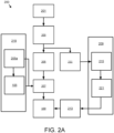
- FIG. 2A is a schematic block diagram of an executable image generation system 200.
- the executable image generation system 200 may develop an executable image 207 for the hardware device 100.
- the system 200 includes core functions 201, a utility tool 203, function block framework source code 205, an application logic editor 209, function block framework descriptions 211, the executable image 207, application logic 213, and a development library 219.
- the function block framework 125 and the function block core 130 may be stored as reusable library elements in the development library 219.
- the function block framework 125 may be stored in the development library 219 as function block framework source code 205a as shown.
- the development library 219 may contain common function block framework source code 205a and logic engines 105 for one or more hardware devices 100.
- the common function block source code 205a may realize fundamental algorithms.
- the device developer may develop the core functions 201.
- the core functions 201 are developed in a high-level source code language or generated by other tools like MATLAB/Simulink.
- the high-level source code language may by C, C++, C sharp, Java, Java Script, Python, and the like.
- the utility tool 203 may generate function block framework source code 205 from the core functions 201.
- the function block framework source code 205 may include one or more of common function block framework source code 205a from the reusable library elements and custom function block framework source code 205.
- the utility tool 203 may generate a function block framework description 211 from the core functions 201.
- the function block framework description 211 may be an extensible markup language (XML) file.
- the logic engine 105 may process the common function blocks 155 from the common function block framework source code 205a through a specific interface of the function blocks 155.
- the logic engine 105 may also process function blocks 155 constructed with function block framework source code 205 and a core function 201.
- the development library 219 may further include logic engines 105 for one or more hardware devices 100.
- the library developer may add logic engines 105 to the development library 219.
- the logic engines 105 may be accessible for use by the executable image 207.
- the logic program editor 209 may include a function block information interpreter 215.
- the editor developer may create and/or modify the function block information interpreter 215.
- the function block information interpreter 215 may generate visualized function blocks 221 from the function block framework description 211.
- the visualized function blocks 221 may be presented as signal logic blocks, Boolean logic blocks, combinational logic blocks, Boolean equations, and the like.
- a user and/or computer may employ the visualized function blocks 221 in generating the application logic 213 that interfaces with the hardware device 100.
- the application logic 213 may include common function blocks 155 from common function block source code 205a and custom function blocks 155 from function block framework source code 205.
- Figure 2B is a schematic block diagram of an executable image generation process 300.
- the process 300 may employ the executable image generation system 200 to generate the executable image 207 for the hardware device 100.
- the executable image 207 may comprise the function block framework 125, the function block core 130 and other functions.
- the utility tool 203 generates the function block framework source code 205 and the function block framework description 211.
- the utility tool 203 may generate the function block test description 223.
- the device developer employs the utility tool 203 to define and generate the function block framework source code 205, the function block framework description 211, and/or the function block test description 223.
- the device developer may require no knowledge of the logic engine 105, device memory 110, and/or communication hardware 120.
- the function block framework source code 205 is integrated with function block core function source code 319 for a logic engine 105 to be a part of a device firmware project 317.
- the device firmware project 317 may be compiled to generate the executable image 207 for the hardware device 100.
- the function block description 211 may be used by the application logic editor 209 to generate configuration parameters 227 for the hardware device 100.
- the test function block description 223 may be used by an automated test tool 225 to generate test vectors 229 for the hardware device 100.
- the automated test tool 225 may further employ the test function block description 223 to test the executable image 207 on the hardware device 100.
- the test vectors 229 may be used to test the executable image 207 on the hardware device 100.
- the tested hardware device 100 configured with the configuration parameters 227 and executable image 207 may be released for use.
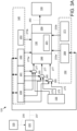
- Figure 3A is a schematic block diagram of function block communications.
- the depicted embodiment includes the function block core 130.
- the function block core 130 may reside in the device memory 110 and executes on the logic engine 105.
- the function block core 130 gets data through an input interface 249 and output data through an output interface 259.
- the input interface 249 and the output interface 259 are embodied in the function block framework 125.
- the function block core 130 may access the nonvolatile memory 145 and/or the volatile memory 150.
- the nonvolatile memory 145 and the volatile memory 150 may be in communication 237 with a function block service 231.
- the function block service 231 may communicate 235 via the communication hardware 120.
- the function block service 231 instantiates the function block framework 125 to the nonvolatile memory 145 and/or to the volatile memory 150.
- the nonvolatile memory 145 may store input constants 239, input binding paths 241, nonvolatile parameters with attribute identifiers 243, and nonvolatile parameters without attribute identifiers 253. Attribute identifiers support accessing parameters through the function block service 231 from outside of the hardware device 100. In one embodiment, the nonvolatile parameters with attribute identifiers 243 and nonvolatile parameters without attribute identifiers 253 are directly accessible 273a-b by the function block core 130.
- the volatile memory 150 may store volatile parameters with attribute identifiers 269 and volatile parameters without attribute identifiers 271.
- the volatile parameters with attribute identifiers 269 and volatile parameters without attribute identifiers 271 may be directly accessible 233a-b by the function block core 130.
- the function block core 130 accesses table inputs 275 from the data table 135 and/or the input constants 239 selected by input binding paths 241 via the input interface 249.
- Selectors 265 select either data from the data table 135 or one of an input constant 239 based on the input binding paths 241 for input 277 to the input interface 249.
- the use of the selectors 265 is technical solution that routes data in an unconventional manner to improve the functionality of the function block core 130.
- the selectors 265 improve the retrieval of data from the data table 135 by selecting between the input constants 239 and the table inputs 275. Based on the input binding paths 241, either an input constant 239 or a table input 275 is communicated to the input interface 249 and the function block core 130. As a result, the operation of the function block core 130 is enhanced.
- the function block framework 125 may specify that the table inputs 275 are from one of the secondary data table 140 in the volatile memory 150 and the data table 135 in the nonvolatile memory 145.
- the function block core 130 may further put 263 data to the data table 135 via the output interface 259.
- Figure 3B is a schematic block diagram of function block processing.
- a function block configuration 301 is shown with the plurality of executable images 207.
- the plurality of executable images 207 may reside in the nonvolatile memory 145.
- Function blocks and/or core functions 201 of the plurality of executable images 207 may be executed sequentially as shown.
- function block run-time data 303 with a plurality of function block data 208 is shown.
- the function block data 208 may reside in the volatile memory 150.
- Each instance of function block data 208 may be employed by a corresponding executable image 207.
- Figure 3C is a schematic block diagram of the utility tool operation.
- the utility tool 203 receives the definitions of core function 201.
- the utility tool may receive function block core function source code 319.
- the utility tool 203 may generate function block data 333 and function block functions 341 for the function block framework source code 205.
- the utility tool 203 may generate the function block framework descriptions 211.
- the utility tool 203 generates a function block process function 351 for the function block framework source code 205.
- the utility tool 203 generates function block management data 357 for the function block framework source code 205.
- the function block data 333 may include function block input definitions 335, function block output definitions 337, and function block parameter definitions 339.
- the function block input definitions 335 may define combinations of input constants 239, input binding paths 241, and data from the data table 135 for input 277 to the function block core 130.
- the function block output definitions 337 may define data that is output 263 to the data table 135.
- the function block parameter definitions 339 may define the nonvolatile parameters with attribute identifiers 243, nonvolatile parameters without attribute identifiers 253, volatile parameters with attribute identifiers 269, and volatile parameters without attribute identifiers 271.
- the function block functions 341 include a function block instantiation function 343, a function block initialization function 345, a function block verification function 347, and a function block attribute get/set function 349.
- the function block instantiation function 343 may instantiate the function block framework source code 205 and/or the function block core function source code 319 as the executable image 207.
- the function block initialization function 345 may initialize the executable image 207 on the logic engine 105.
- the function block verification function 347 may verify the instantiation and/or initialization of the executable image 207 on the logic engine 105.
- the function block verification function 347 may validate parameters 243/253/269/271.
- the function block attribute get/set function 349 may establish communications between the function block service 231 and the executable image 207.
- the function block process function 351 may enable the function block framework 125 of the executable image 207 to interface with the function block core 130.
- the function block process function 351 presents a standard interface to communicate with the function block core 130, transferring inputs 277 to the function block core 130 and returning the outputs 263.
- the function block management data 257 may store management data that is used to organize function block types, including one or more classes, constants, and the like.
- the function block framework 125 defines a standard interface to the function block core 130, employing conventional elements in an unconventional way to allow core functions 201 to interface directly with the function block core 130.
- standard core functions 201 may be used by nonstandard logic engines 105.
- device developers with little experience with the function block core 130 may rapidly and efficiently create executable code 207 for a unique function block core 130 of a highly distinguished hardware device 100. Thus the development of the executable code 207 is greatly enhanced.
- Figure 3D shows a plurality of data tables 135 and a plurality of secondary data tables 140.
- the plurality of data tables 135 and/or plurality of secondary data tables 140 may communicate inputs 277 to the executable code 207.
- the plurality of data tables 135 and/or plurality of secondary data tables 140 may receive puts 263 from the executable code 207.
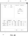
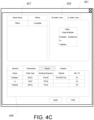
- Figures 4A-D are drawings of user interfaces 421 of the utility tool 203.
- the user interface 421 includes a function block table 427, a logic design block editor view 426, and a general input screen 429.
- the function block table 427 may list one or more function blocks and a corresponding status.
- the logic design block editor view 426 may display and/or support the entry of a logic design for the function block framework 125 and/or core functions 201.
- the general input screen 429 may receive one or more descriptions including a class code, an application scope, an instruction name, an instruction identifier, and/or an instruction revision. In addition, the general input screen 429 may receive a function block description 428.
- a function block editor view 425 is shown.
- the function block editor view 425 supports the definitions of the inputs 277 and outputs 263 as core functions 201 for the function block core 130.
- a parameter screen 431 is shown.
- the parameter screen 431 may define a datatype, a value, a read/write parameter, an observable parameter, a volatile parameter, an accessibility parameter, an identifier, and/or input verification rules for each parameter.
- an input screen 435 is shown.
- the input screen 435 may define a datatype, a binding requirement, a default value, and/or an attribute identifier for each input 277.
- an output screen 433 is shown.
- the output screen 433 may define a data type for each output 263.
- Figure 4E is a schematic block diagram of utility tool data 440.
- the utility tool data 440 includes general information 441 from the general input screen 429, input definitions 443 from the input screen 435, input verification rules 445 from the input screen 435, output definitions 447 from the output screen 433, and parameter definitions 449 from the parameter screen 431.
- the input definitions 443 specify that bindings are one of required and not required for each function block input 277.
- the function block framework 125 may define one or more of the function block inputs 277, the function block outputs 263, and the function block parameters 273 from one or more of the general information 441, the input definitions 443, an input verification rules 445, the output definitions 447, and the parameters definitions 449.
- Figure 5 is a schematic block diagram of a computer 400.
- the computer 400 may generate the function block framework 125 and/or instantiate the function block framework 125 and the function block core 130 as the executable image 207.
- the computer 400 may be embodied in the automated test tool 225 and/or the logic engine 105.
- the computer 400 includes a processor 405, a memory 410, and communication hardware 415.
- the memory 410 may include a semiconductor storage device, hard disk drive, an optical storage device, a micromechanical storage device, or combinations thereof.
- the memory 410 may store code.
- the processor 405 may execute the code.
- the communication hardware 415 may communicate with other devices.
- Figure 6A is a schematic flow chart diagram of a executable image instantiating method 500.
- the method 500 may instantiate the function block framework 125 and the function block core 130 as the executable image 207.
- the method 500 may execute the executable image 207 with the logic engine 105.
- the method 500 may be performed by the processor 405 of the computer 400 and/or the logic engine 105.
- the method 500 starts, and in one embodiment, the processor 405 generates 501 the function block core source code 319 for the function block core 130.
- the function block core source code 319 may be generated 501 by a source code editor.
- the processor 405 may generate 503 the function block framework 125 for the hardware device 100 as shown in Figure 3D .
- the function block framework 125 may be generated 503 using the utility tool 203.
- the function block framework 125 may comprise the function block framework source code 205 and the function block framework description 211.
- the function block framework 125 and the function block core 130 may be organized as object oriented code.
- the function block framework 125 and the function block core 130 may be stored as reusable library elements in the development library 219.
- the function block framework 125 presents a standard interface to the function block core 130 executed by the logic engine 105.
- the generation 503 of the function block framework 125 is described in more detail in Figure 6B .
- the processor 405 generates 505 the application logic 213.
- the generation 505 of the application logic 213 is described in more detail in Figure 6D .
- the processor 405 may instantiate 507 the function block framework 125 and the function block core 130 as the executable image 207 for the hardware device 100.
- the function block framework source code 205 and the function block core function source code 319 are compiled and linked to form the executable image 207.
- the processor 405 may configure 509 the logic engine 105 to execute the executable image 207 using the function block framework description 211.
- the processor 405 may define one or more ports, logical channels, data names, and the like to configure 509 the logic engine 105.
- the logic engine 105 executes 511 the executable image 207 and the method 500 ends.
- the execution 511 of the executable image 207 by the logic engine 105 may control the automation hardware 115 of the hardware device 100.
- the hardware device 100 operates in an industrial environment.
- the instantiation 507 of the executable image 207 is the result of a combined order of specific rules that render the information of the function block core source code 319 and the core functions 201 into the specific formats of the function block framework source code 205 and function block framework descriptions 211 of the function block framework 125.
- the specific rules further render the function block framework source code 205 and the function block framework descriptions 211 into the executable code 207 and the application logic 213 that execute on the hardware device 100.
- the specific process embodied in the specific rules enhance and improve the function of the computer 400.
- Figure 6B is a schematic flow chart diagram of a function block framework generation method 550.
- the method 550 may generate the function block framework 125.
- the method 550 may perform step 503 of Figure 6A .
- the method 550 may be performed by the processor 405 of the computer 400.
- the method 550 starts, and in one embodiment, the processor 405 receives 551 the core functions 201.
- the core functions 201 may be developed by the device developer. In one embodiment, the core functions 201 are developed using the utility tool 203. The core functions 201 may be developed via the user interfaces 421 of the utility tool 203. The core functions 201 may be custom core functions 201.
- the core functions 201 may include the general information 441, the input definitions 443, the input verification rules 445, the output definitions 447, and/or the parameter definitions 449.
- the processor 405 may generate 553 custom function block framework source code 205 from the core functions 201.
- the function block framework source code 205 may be generated 553 with the user interface 421 of the utility tool 203.
- the function block framework 125 may be generated 503 using one or more of the graphical entry 425 and the tabular entry 423 of the user interface 421.
- the processor 405 parses the core functions 201 into one or more atomic functions.
- the processor 405 may translate the atomic functions into the custom function block framework source code 205.
- the processor 405 may further retrieve 555 common function block framework source code 205a from the development library 219.
- the common function block framework source code 205a is referenced by the core functions 201.
- the common function block framework source code 205a may be referenced by the custom function block framework source code 205.
- the processor 405 may integrate 557 the custom function block framework source code 205 and the common function block framework source code 205 as the function block framework source code 205.
- the function block framework source code 205 may include one or more of common function block framework source code 205a from the reusable library elements of custom function block framework source code 205.
- the processor 405 may further generate 559 the function block framework description 211 from the core functions 201 and the method 550 ends.
- the processor 405 may identify configuration parameters 227 that interface the function block framework 125 to the core logic 130 and the logic engine 105.
- Figure 6C is a schematic flow chart diagram of a function block test method 600.
- the method 600 may test the function block framework 125.
- the method 600 may be performed by the processor 405 of the computer 400 and/or the logic engine 105.
- the method 600 starts, and in one embodiment, the processor 405 generates 601 test vectors 229 from the test function block description 223.
- the test vectors 229 may be organized to exercise each core function 201.
- the test vectors 229 may be organized to exercise the function block framework 125.
- each test vector 229 includes one or more commands and data and one or more corresponding expected results.
- the processor 405 may test 603 the executable image 207 with the test vectors 229.
- the processor 405 may communicate commands and data from the test vector 229 to the hardware device 100 and monitor results from the hardware device 100.
- the processor identifies 605 test vector failures and the method 600 ends.
- the expected results from the test vector 229 do not match monitored results from the hardware device 100 in a test vector failure.
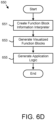
- Figure 6D is a schematic flow chart diagram of an application logic generation method 650.
- the method 650 may generate the application logic 213.
- the method 650 performs step 505 of Figure 6A .
- the method 650 may be performed by the processor 405 of the computer 400.
- the method 650 starts, and in one embodiment, the processor 405 creates 651 the function block information interpreter 215.
- the function block information interpreter 215 may be based on the function block framework description 211.
- the function block framework description 211 may define one or more signal logic blocks, Boolean logic blocks, combination a logic blocks, Boolean equations, and the like.
- the processor 405 may generate 653 the visualized function blocks 221 from the function block framework description 211 using the function block information interpreter 215.
- the function block information interpreter 215 may render the function block framework description 211 as visualized function blocks 221.
- the visualized function blocks 221 may depict a logic design, function blocks, and the like.
- the processor 405 may generate 655 the application logic 213 from the visualized function blocks 221 and the method 650 ends.
- the application logic 213 may be generated 655 from common function blocks 155 from the common function block source code 205a and custom function blocks 155 from the function block framework source code 205.
- the application logic 213 may be generated 655 to interface the visualized function blocks 221 to the logic engine 105.
- the embodiments speed the development of function blocks 155 for hardware devices 100 by providing a standardized framework utilizing a series of development steps that allows multiple developers with expertise in specific areas to contribute to the final executable image 207.
- the embodiments further support improved verification and validation of the executable images 207. As a result, executable images 207 are developed more rapidly and with reduced bugs.
- the embodiments further separate the development and release of function blocks 155 from the development and release of function block cores 130, simplifying the development of both function blocks 155 and function block cores 130.
- the embodiments also enable multiple different developers with different expertise to share functions blocks 155 and function block cores 130, reducing parallel development and increasing code quality.
Landscapes
- Engineering & Computer Science (AREA)
- Software Systems (AREA)
- Theoretical Computer Science (AREA)
- General Engineering & Computer Science (AREA)
- Physics & Mathematics (AREA)
- General Physics & Mathematics (AREA)
- Computer Hardware Design (AREA)
- Quality & Reliability (AREA)
- Computing Systems (AREA)
- Stored Programmes (AREA)
Claims (15)
- Verfahren zur Steuerung von Automatisierungs-Hardware, die zur Ausführung einer Automatisierungsfunktion in einer Industrieumgebung konfiguriert ist, wobei das Verfahren Folgendes umfasst:Erzeugen (503), unter Verwendung eines Prozessors (405), eines Funktionsblock-Frameworks (125) für eine Hardware-Vorrichtung (100), die konfiguriert ist, um in der Industrieumgebung zu arbeiten, wobei das Funktionsblock-Framework einen Funktionsblock-Framework-Quellcode (205) und eine Funktionsblock-Framework-Beschreibung (211) umfasst, wobei die Hardware-Vorrichtung eine Logik-Engine (105) und Automatisierungs-Hardware (115) umfasst, die konfiguriert ist, um eine Automatisierungsfunktion in der Industrieumgebung auszuführen, und das Funktionsblock-Framework eine Standardschnittstelle darstellt, um mit einem Funktionsblockkern (130) zu kommunizieren, die Eingaben (277) an den Funktionsblockkern überträgt und Ausgaben (263) zurückgibt, wobei der Funktionsblockkern konfiguriert ist, um Daten über eine Eingangsschnittstelle (249) zu erhalten und Daten über eine Ausgangsschnittstelle (259) auszugeben, wobei die Eingangsschnittstelle und die Ausgangsschnittstelle in dem Funktionsblock-Framework verkörpert sind, wobei der Funktionsblockkern konfiguriert ist, um auf der Logik-Engine ausgeführt zu werden, um die Hardware-Vorrichtung zu steuern, wobei der Funktionsblockkern ferner konfiguriert ist, um auf Tabelleneingaben (275) aus einer Datentabelle (135) und/oder Eingabekonstanten (239) über die Eingabeschnittstelle zuzugreifen, und wobei ein Selektor (265) konfiguriert ist, um entweder Daten aus der Datentabelle oder eine der Eingabekonstanten basierend auf einem Eingabebindungspfad (241) zur Eingabe in die Eingabeschnittstelle auszuwählen;Instanziierung (507) des Funktionsblock-Frameworks und des Funktionsblockkerns als ausführbares Image (207) für die Hardware-Vorrichtung;Konfigurieren (509) der Logik-Engine zur Ausführung des ausführbaren Images unter Verwendung der Funktionsblock-Framework-Beschreibung; undSteuern der Automatisierungs-Hardware der Hardware-Vorrichtung durch Ausführen (511) des ausführbaren Images mit der Logik-Engine.
- Verfahren nach Anspruch 1, wobei das Verfahren ferner das Erzeugen von Funktionsblockkern-Quellcode für den Funktionsblockkern umfasst.
- Verfahren nach Anspruch 1 oder 2, wobei das Funktionsblock-Framework ferner eine Test-Funktionsblock-Beschreibung umfasst, die von einem automatisierten Testwerkzeug zum Testen des ausführbaren Images auf der Hardware-Vorrichtung verwendet wird.
- Verfahren nach einem der Ansprüche 1 bis 3, wobei das Funktionsblock-Framework einen oder mehrere Funktionsblockeingänge, Funktionsblockausgänge und Funktionsblockparameter aus einer oder mehreren allgemeinen Informationen, einer Eingangsdefinition, einer Eingangsüberprüfungsregel, einer Ausgangsdefinition und einer Parameterdefinition definiert.
- Verfahren nach Anspruch 4, wobei die Funktionsblockparameter Funktionsblockparameter mit Attributkennungen und Funktionsblockparameter ohne Attributkennungen umfassen, wobei Funktionsblockparameter mit Attributkennungen außerhalb der Hardware-Vorrichtung zugänglich sind.
- Verfahren nach Anspruch 4, bei dem die Funktionsblockeingänge entweder aus Eingangskonstanten oder Tabelleneingängen aus einer Datentabelle ausgewählt werden, und/oder
wobei die Datentabelle einen flüchtigen und einen nichtflüchtigen Speicher umfasst und das Funktionsblock-Framework festlegt, dass die Tabelleneingänge entweder aus dem flüchtigen oder dem nichtflüchtigen Speicher stammen. - Verfahren nach Anspruch 6, wobei die Eingangsdefinitionen für jeden Funktionsblockeingang festgelegen, dass Bindungen erforderlich oder nicht erforderlich sind.
- Verfahren nach einem der Ansprüche 1 bis 7, wobei das Funktionsblock-Framework mit einer Benutzeroberfläche erzeugt wird, die eine grafische Eingabe und/oder eine tabellarische Eingabe umfasst.
- Verfahren nach einem der Ansprüche 1 bis 8, wobei das Funktionsblock-Framework und der Funktionsblockkern als objektorientierter Code organisiert sind.
- Verfahren nach einem der Ansprüche 1 bis 9, wobei das Funktionsblock-Framework und der Funktionsblockkern als wiederverwendbare Bibliothekselemente gespeichert sind; und/oder
wobei der Funktionsblock-Framework-Quellcode einen oder mehrere gemeinsame Funktionsblock-Framework-Quellcodes aus den wiederverwendbaren Bibliothekselementen und benutzerdefinierte Funktionsblock-Framework-Quellcodes umfasst. - Vorrichtung, die Folgendes umfasst:einen Prozessor (405);einen Speicher (410), der Code speichert, der durch den Prozessor ausführbar ist, um ein Verfahren zur Steuerung von Automatisierungs-Hardware durchzuführen, die konfiguriert ist, um eine Automatisierungsfunktion in einer Industrieumgebung durchzuführen, wobei das Verfahren Folgendes umfasst:Erzeugen (503) eines Funktionsblock-Frameworks (125) für eine Hardware-Vorrichtung (100), die konfiguriert ist, um in der Industrieumgebung zu arbeiten, wobei das Funktionsblock-Framework einen Funktionsblock-Framework-Quellcode (205) und eine Funktionsblock-Framework-Beschreibung (211) umfasst, wobei die Hardware-Vorrichtung eine Logik-Engine (105) und Automatisierungs-Hardware (115) umfasst, die konfiguriert ist, um eine Automatisierungsfunktion in der Industrieumgebung auszuführen, und das Funktionsblock-Framework eine Standardschnittstelle darstellt, um mit einem Funktionsblockkern (130) zu kommunizieren, die Eingaben (277) an den Funktionsblockkern überträgt und Ausgaben (263) zurückgibt, wobei der Funktionsblockkern konfiguriert ist, um Daten über eine Eingangsschnittstelle (249) zu erhalten und Daten über eine Ausgangsschnittstelle (259) auszugeben, wobei die Eingangsschnittstelle und die Ausgangsschnittstelle in dem Funktionsblock-Framework verkörpert sind, wobei der Funktionsblockkern konfiguriert ist, um auf der Logik-Engine ausgeführt zu werden, um die Hardware-Vorrichtung zu steuern, wobei der Funktionsblockkern ferner konfiguriert ist, um auf Tabelleneingaben (275) aus einer Datentabelle (135) und/oder Eingabekonstanten (239) über die Eingabeschnittstelle zuzugreifen, und wobei ein Selektor (265) konfiguriert ist, um entweder Daten aus der Datentabelle oder eine der Eingabekonstanten auf der Grundlage eines Eingabebindungspfads (241) zur Eingabe in die Eingabeschnittstelle auszuwählen;Instanziierung (507) des Funktionsblock-Frameworks und des Funktionsblocckerns als ausführbares Image (207) für die Hardware-Vorrichtung;Konfigurieren (509) der Logik-Engine zur Ausführung des ausführbaren Images unter Verwendung der Funktionsblock-Framework-Beschreibung; undSteuern der Automatisierungs-Hardware der Hardware-Vorrichtung durch Ausführen (511) des ausführbaren Images mit der Logik-Engine.
- Vorrichtung nach Anspruch 11, wobei der Prozessor ferner Funktionsblockkern-Quellcode für den Funktionsblockkern erzeugt.
- Vorrichtung nach Anspruch 11 oder 12, wobei das Funktionsblock-Framework ferner eine Test-Funktionsblock-Beschreibung umfasst, die von einem automatisierten Testwerkzeug zum Testen des ausführbaren Images auf der Hardware-Vorrichtung verwendet wird; oder wobei das Funktionsblock-Framework einen oder mehrere Funktionsblockeingänge, Funktionsblockausgänge und Funktionsblockparameter aus einer oder mehreren allgemeinen Informationen, einer Eingangsdefinition, einer Eingangsüberprüfungsregel, einer Ausgangsdefinition und einer Parameterdefinition definiert.
- Computerprogrammprodukt, das ein nicht-flüchtiges, computerlesbares Speichermedium (410) mit darin verkörpertem Programmcode umfasst, wobei der Programmcode von einem Prozessor (405) lesbar/ausführbar ist, um ein Verfahren zur Steuerung von Automatisierungs-Hardware auszuführen, die zur Ausführung einer Automatisierungsfunktion in einer industriellen Umgebung konfiguriert ist, wobei das Verfahren Folgendes umfasst:Erzeugen (503) eines Funktionsblock-Frameworks (125) für eine Hardware-Vorrichtung (100), die konfiguriert ist, um in der Industrieumgebung zu arbeiten, wobei das Funktionsblock-Framework einen Funktionsblock-Framework-Quellcode (205) und eine Funktionsblock-Framework-Beschreibung (211) umfasst, wobei die Hardware-Vorrichtung eine Logik-Engine (105) und Automatisierungs-Hardware (115) umfasst, die konfiguriert ist, um eine Automatisierungsfunktion in der Industrieumgebung auszuführen, und das Funktionsblock-Framework eine Standardschnittstelle darstellt, um mit einem Funktionsblockkern (130) zu kommunizieren, die Eingaben (277) an den Funktionsblockkern überträgt und Ausgaben (263) zurückgibt, wobei der Funktionsblockkern konfiguriert ist, um Daten über eine Eingangsschnittstelle (249) zu erhalten und Daten über eine Ausgangsschnittstelle (259) auszugeben, wobei die Eingangsschnittstelle und die Ausgangsschnittstelle in dem Funktionsblock-Framework verkörpert sind, wobei der Funktionsblockkern konfiguriert ist, um auf der Logik-Engine ausgeführt zu werden, um die Hardware-Vorrichtung zu steuern, wobei der Funktionsblockkern ferner konfiguriert ist, um auf Tabelleneingaben (275) aus einer Datentabelle (135) und/oder Eingabekonstanten (239) über die Eingabeschnittstelle zuzugreifen, und wobei ein Selektor (265) konfiguriert ist, um entweder Daten aus der Datentabelle oder eine der Eingabekonstanten auf der Grundlage eines Eingabebindungspfads (241) zur Eingabe in die Eingabeschnittstelle auszuwählen;Instanziierung (507) des Funktionsblock-Frameworks und des Funktionsblocckerns als ausführbares Image (207) für die Hardware-Vorrichtung;Konfigurieren (509) der Logik-Engine zur Ausführung des ausführbaren Images unter Verwendung der Funktionsblock-Framework-Beschreibung; undSteuern der Automatisierungs-Hardware der Hardware-Vorrichtung durch Ausführen (511) des ausführbaren Images mit der Logik-Engine.
- Computerprogrammprodukt nach Anspruch 14, wobei der Prozessor ferner Funktionsblockkern-Quellcode für den Funktionsblockkern erzeugt; oderwobei das Funktionsblock-Framework ferner eine Test-Funktionsblock-Beschreibung umfasst, die von einem automatisierten Testwerkzeug zum Testen des ausführbaren Images auf der Hardware-Vorrichtung verwendet wird; oderwobei das Funktionsblock-Framework einen oder mehrere Funktionsblockeingänge, Funktionsblockausgänge und Funktionsblockparameter aus einer oder mehreren allgemeinen Informationen, einer Eingangsdefinition, einer Eingangsüberprüfungsregel, einer Ausgangsdefinition und einer Parameterdefinition definiert.
Applications Claiming Priority (1)
| Application Number | Priority Date | Filing Date | Title |
|---|---|---|---|
| US16/237,467 US10747508B2 (en) | 2018-12-31 | 2018-12-31 | Function block framework generation |
Publications (2)
| Publication Number | Publication Date |
|---|---|
| EP3674886A1 EP3674886A1 (de) | 2020-07-01 |
| EP3674886B1 true EP3674886B1 (de) | 2024-01-24 |
Family
ID=69005383
Family Applications (1)
| Application Number | Title | Priority Date | Filing Date |
|---|---|---|---|
| EP19218955.3A Active EP3674886B1 (de) | 2018-12-31 | 2019-12-20 | Funktionsblockrahmenerzeugung |
Country Status (3)
| Country | Link |
|---|---|
| US (1) | US10747508B2 (de) |
| EP (1) | EP3674886B1 (de) |
| CN (1) | CN111580789B (de) |
Families Citing this family (4)
| Publication number | Priority date | Publication date | Assignee | Title |
|---|---|---|---|---|
| CN114840221A (zh) * | 2022-04-15 | 2022-08-02 | 医渡云(北京)技术有限公司 | 云服务器部署方法、装置、系统、存储介质及计算机设备 |
| CN115167842A (zh) * | 2022-07-19 | 2022-10-11 | 平安国际融资租赁有限公司 | 业务的可视化开发方法、装置、系统、电子设备及介质 |
| CN115576593B (zh) * | 2022-12-12 | 2023-07-14 | 广州市易鸿智能装备有限公司 | 工业互联软件运行方法、装置、电子设备及存储介质 |
| WO2025025092A1 (zh) * | 2023-07-31 | 2025-02-06 | 西门子股份公司 | 生成复合功能块的方法、装置、电子设备和存储介质 |
Family Cites Families (15)
| Publication number | Priority date | Publication date | Assignee | Title |
|---|---|---|---|---|
| US7822495B2 (en) * | 2002-04-15 | 2010-10-26 | Fisher-Rosemount Systems, Inc. | Custom function blocks for use with process control systems |
| WO2008021777A2 (en) * | 2006-08-07 | 2008-02-21 | National Instruments Corporation | Formal verification of graphical programs |
| US8726241B1 (en) | 2007-06-06 | 2014-05-13 | Rockwell Collins, Inc. | Method and system for the development of high-assurance computing elements |
| US9134720B2 (en) | 2010-02-12 | 2015-09-15 | Rockwell Automation Technologies, Inc. | Macro function block for encapsulating device-level embedded logic |
| US8352936B2 (en) * | 2010-04-06 | 2013-01-08 | International Business Machines Corporation | Creating virtual appliances |
| US8661132B2 (en) * | 2010-05-28 | 2014-02-25 | International Business Machines Corporation | Enabling service virtualization in a cloud |
| US9069598B2 (en) * | 2012-01-06 | 2015-06-30 | International Business Machines Corporation | Providing logical partions with hardware-thread specific information reflective of exclusive use of a processor core |
| CN104254835B (zh) | 2012-04-12 | 2017-08-15 | 汉阳大学校产学协力团 | 软件定义的无线电应用的分发、设置及执行方法 |
| US9081583B2 (en) * | 2012-08-23 | 2015-07-14 | National Instruments Corporation | Compile time execution |
| US9720703B2 (en) * | 2012-11-26 | 2017-08-01 | International Business Machines Corporation | Data driven hardware chips initialization via hardware procedure framework |
| US9519466B2 (en) * | 2013-12-20 | 2016-12-13 | Oracle International Corporation | Executable code for constrained computing environments |
| US20150339127A1 (en) * | 2014-05-23 | 2015-11-26 | National Instruments Corporation | Configuration Change Tracking for Measurement Devices |
| US10140149B1 (en) * | 2015-05-19 | 2018-11-27 | Pure Storage, Inc. | Transactional commits with hardware assists in remote memory |
| US9870206B2 (en) * | 2015-11-10 | 2018-01-16 | National Instruments Corporation | Replication structure in a graphical programming language |
| CN108958724A (zh) * | 2018-06-26 | 2018-12-07 | 北京优锘科技有限公司 | 三维可视化引擎构建方法、装置、引擎、浏览器、设备及存储介质 |
-
2018
- 2018-12-31 US US16/237,467 patent/US10747508B2/en active Active
-
2019
- 2019-12-20 EP EP19218955.3A patent/EP3674886B1/de active Active
- 2019-12-27 CN CN201911375306.4A patent/CN111580789B/zh active Active
Non-Patent Citations (1)
| Title |
|---|
| ANONYMOUS: "Cat S41 smartphone review | TechRadar", 1 November 2017 (2017-11-01), pages 1 - 10, XP055851020, Retrieved from the Internet <URL:http://web.archive.org/web/20171101200625/https://www.techradar.com/reviews/cat-s41> [retrieved on 20211013] * |
Also Published As
| Publication number | Publication date |
|---|---|
| US10747508B2 (en) | 2020-08-18 |
| US20200210154A1 (en) | 2020-07-02 |
| CN111580789B (zh) | 2023-09-12 |
| CN111580789A (zh) | 2020-08-25 |
| EP3674886A1 (de) | 2020-07-01 |
Similar Documents
| Publication | Publication Date | Title |
|---|---|---|
| JP7050106B2 (ja) | 実行可能分析モジュールをインスタンス化する方法 | |
| US10360141B2 (en) | Automated application test system | |
| CN108885545B (zh) | 用于实时数据流编程语言的工具和方法 | |
| AU2018365860B2 (en) | Code module selection for device design | |
| EP3674886A1 (de) | Funktionsblockrahmenerzeugung | |
| US20210326500A1 (en) | Generation of dynamic design flows for integrated circuits | |
| US20150052596A1 (en) | Network based firmware feature configuration and firmware image generation | |
| WO2015085152A1 (en) | Managing interfaces for dataflow graphs composed of sub-graphs | |
| US20210103514A1 (en) | Reusable test cases for identifiable patterns | |
| CN109284222B (zh) | 软件单元、数据处理系统中的项目测试方法、装置及设备 | |
| US10185472B2 (en) | Method for providing a user interface, computer system and computer program product | |
| CN113448678A (zh) | 应用信息生成方法、部署方法及装置、系统、存储介质 | |
| Melo et al. | Development and deployment of complex robotic applications using containerized infrastructures | |
| KR20210060203A (ko) | 마이크로서비스 구조 재구성 방법 및 장치 | |
| CN113656001B (zh) | 平台组件开发方法、装置、计算机设备及存储介质 | |
| US20210271458A1 (en) | Managing an app method and system | |
| Paikan et al. | A generic testing framework for test driven development of robotic systems | |
| CN114138321B (zh) | 一种小程序审核方法和系统 | |
| CN118259906B (zh) | 一种基于PaaS框架的多端页面适配方法、设备及介质 | |
| US8745587B2 (en) | System and method for testing computer programs | |
| CN120723280A (zh) | 汽车开放系统架构的目标文件更新方法和装置 | |
| Furriel et al. | Jurassic park-a centralized software modules repository for iot devices | |
| WO2022184264A1 (en) | Platform and method for building and deploying software applications | |
| Samson et al. | Automatic generation of test oracles from component based software architectures | |
| CN114647435B (zh) | 一种应用配置方法、装置、电子设备及可读存储介质 |
Legal Events
| Date | Code | Title | Description |
|---|---|---|---|
| PUAI | Public reference made under article 153(3) epc to a published international application that has entered the european phase |
Free format text: ORIGINAL CODE: 0009012 |
|
| STAA | Information on the status of an ep patent application or granted ep patent |
Free format text: STATUS: THE APPLICATION HAS BEEN PUBLISHED |
|
| AK | Designated contracting states |
Kind code of ref document: A1 Designated state(s): AL AT BE BG CH CY CZ DE DK EE ES FI FR GB GR HR HU IE IS IT LI LT LU LV MC MK MT NL NO PL PT RO RS SE SI SK SM TR |
|
| AX | Request for extension of the european patent |
Extension state: BA ME |
|
| STAA | Information on the status of an ep patent application or granted ep patent |
Free format text: STATUS: REQUEST FOR EXAMINATION WAS MADE |
|
| 17P | Request for examination filed |
Effective date: 20210104 |
|
| RBV | Designated contracting states (corrected) |
Designated state(s): AL AT BE BG CH CY CZ DE DK EE ES FI FR GB GR HR HU IE IS IT LI LT LU LV MC MK MT NL NO PL PT RO RS SE SI SK SM TR |
|
| STAA | Information on the status of an ep patent application or granted ep patent |
Free format text: STATUS: EXAMINATION IS IN PROGRESS |
|
| 17Q | First examination report despatched |
Effective date: 20211025 |
|
| GRAP | Despatch of communication of intention to grant a patent |
Free format text: ORIGINAL CODE: EPIDOSNIGR1 |
|
| STAA | Information on the status of an ep patent application or granted ep patent |
Free format text: STATUS: GRANT OF PATENT IS INTENDED |
|
| INTG | Intention to grant announced |
Effective date: 20230726 |
|
| GRAS | Grant fee paid |
Free format text: ORIGINAL CODE: EPIDOSNIGR3 |
|
| GRAA | (expected) grant |
Free format text: ORIGINAL CODE: 0009210 |
|
| STAA | Information on the status of an ep patent application or granted ep patent |
Free format text: STATUS: THE PATENT HAS BEEN GRANTED |
|
| AK | Designated contracting states |
Kind code of ref document: B1 Designated state(s): AL AT BE BG CH CY CZ DE DK EE ES FI FR GB GR HR HU IE IS IT LI LT LU LV MC MK MT NL NO PL PT RO RS SE SI SK SM TR |
|
| REG | Reference to a national code |
Ref country code: GB Ref legal event code: FG4D |
|
| REG | Reference to a national code |
Ref country code: CH Ref legal event code: EP |
|
| REG | Reference to a national code |
Ref country code: IE Ref legal event code: FG4D |
|
| REG | Reference to a national code |
Ref country code: DE Ref legal event code: R096 Ref document number: 602019045528 Country of ref document: DE |
|
| REG | Reference to a national code |
Ref country code: LT Ref legal event code: MG9D |
|
| REG | Reference to a national code |
Ref country code: NL Ref legal event code: MP Effective date: 20240124 |
|
| PG25 | Lapsed in a contracting state [announced via postgrant information from national office to epo] |
Ref country code: NL Free format text: LAPSE BECAUSE OF FAILURE TO SUBMIT A TRANSLATION OF THE DESCRIPTION OR TO PAY THE FEE WITHIN THE PRESCRIBED TIME-LIMIT Effective date: 20240124 |
|
| PG25 | Lapsed in a contracting state [announced via postgrant information from national office to epo] |
Ref country code: NL Free format text: LAPSE BECAUSE OF FAILURE TO SUBMIT A TRANSLATION OF THE DESCRIPTION OR TO PAY THE FEE WITHIN THE PRESCRIBED TIME-LIMIT Effective date: 20240124 |
|
| PG25 | Lapsed in a contracting state [announced via postgrant information from national office to epo] |
Ref country code: IS Free format text: LAPSE BECAUSE OF FAILURE TO SUBMIT A TRANSLATION OF THE DESCRIPTION OR TO PAY THE FEE WITHIN THE PRESCRIBED TIME-LIMIT Effective date: 20240524 |
|
| PG25 | Lapsed in a contracting state [announced via postgrant information from national office to epo] |
Ref country code: LT Free format text: LAPSE BECAUSE OF FAILURE TO SUBMIT A TRANSLATION OF THE DESCRIPTION OR TO PAY THE FEE WITHIN THE PRESCRIBED TIME-LIMIT Effective date: 20240124 |
|
| PG25 | Lapsed in a contracting state [announced via postgrant information from national office to epo] |
Ref country code: GR Free format text: LAPSE BECAUSE OF FAILURE TO SUBMIT A TRANSLATION OF THE DESCRIPTION OR TO PAY THE FEE WITHIN THE PRESCRIBED TIME-LIMIT Effective date: 20240425 |
|
| REG | Reference to a national code |
Ref country code: AT Ref legal event code: MK05 Ref document number: 1652692 Country of ref document: AT Kind code of ref document: T Effective date: 20240124 |
|
| PG25 | Lapsed in a contracting state [announced via postgrant information from national office to epo] |
Ref country code: HR Free format text: LAPSE BECAUSE OF FAILURE TO SUBMIT A TRANSLATION OF THE DESCRIPTION OR TO PAY THE FEE WITHIN THE PRESCRIBED TIME-LIMIT Effective date: 20240124 Ref country code: RS Free format text: LAPSE BECAUSE OF FAILURE TO SUBMIT A TRANSLATION OF THE DESCRIPTION OR TO PAY THE FEE WITHIN THE PRESCRIBED TIME-LIMIT Effective date: 20240424 |
|
| PG25 | Lapsed in a contracting state [announced via postgrant information from national office to epo] |
Ref country code: ES Free format text: LAPSE BECAUSE OF FAILURE TO SUBMIT A TRANSLATION OF THE DESCRIPTION OR TO PAY THE FEE WITHIN THE PRESCRIBED TIME-LIMIT Effective date: 20240124 |
|
| PG25 | Lapsed in a contracting state [announced via postgrant information from national office to epo] |
Ref country code: AT Free format text: LAPSE BECAUSE OF FAILURE TO SUBMIT A TRANSLATION OF THE DESCRIPTION OR TO PAY THE FEE WITHIN THE PRESCRIBED TIME-LIMIT Effective date: 20240124 |
|
| PG25 | Lapsed in a contracting state [announced via postgrant information from national office to epo] |
Ref country code: RS Free format text: LAPSE BECAUSE OF FAILURE TO SUBMIT A TRANSLATION OF THE DESCRIPTION OR TO PAY THE FEE WITHIN THE PRESCRIBED TIME-LIMIT Effective date: 20240424 Ref country code: NO Free format text: LAPSE BECAUSE OF FAILURE TO SUBMIT A TRANSLATION OF THE DESCRIPTION OR TO PAY THE FEE WITHIN THE PRESCRIBED TIME-LIMIT Effective date: 20240424 Ref country code: LT Free format text: LAPSE BECAUSE OF FAILURE TO SUBMIT A TRANSLATION OF THE DESCRIPTION OR TO PAY THE FEE WITHIN THE PRESCRIBED TIME-LIMIT Effective date: 20240124 Ref country code: IS Free format text: LAPSE BECAUSE OF FAILURE TO SUBMIT A TRANSLATION OF THE DESCRIPTION OR TO PAY THE FEE WITHIN THE PRESCRIBED TIME-LIMIT Effective date: 20240524 Ref country code: HR Free format text: LAPSE BECAUSE OF FAILURE TO SUBMIT A TRANSLATION OF THE DESCRIPTION OR TO PAY THE FEE WITHIN THE PRESCRIBED TIME-LIMIT Effective date: 20240124 Ref country code: GR Free format text: LAPSE BECAUSE OF FAILURE TO SUBMIT A TRANSLATION OF THE DESCRIPTION OR TO PAY THE FEE WITHIN THE PRESCRIBED TIME-LIMIT Effective date: 20240425 Ref country code: FI Free format text: LAPSE BECAUSE OF FAILURE TO SUBMIT A TRANSLATION OF THE DESCRIPTION OR TO PAY THE FEE WITHIN THE PRESCRIBED TIME-LIMIT Effective date: 20240124 Ref country code: ES Free format text: LAPSE BECAUSE OF FAILURE TO SUBMIT A TRANSLATION OF THE DESCRIPTION OR TO PAY THE FEE WITHIN THE PRESCRIBED TIME-LIMIT Effective date: 20240124 Ref country code: BG Free format text: LAPSE BECAUSE OF FAILURE TO SUBMIT A TRANSLATION OF THE DESCRIPTION OR TO PAY THE FEE WITHIN THE PRESCRIBED TIME-LIMIT Effective date: 20240124 Ref country code: AT Free format text: LAPSE BECAUSE OF FAILURE TO SUBMIT A TRANSLATION OF THE DESCRIPTION OR TO PAY THE FEE WITHIN THE PRESCRIBED TIME-LIMIT Effective date: 20240124 |
|
| PG25 | Lapsed in a contracting state [announced via postgrant information from national office to epo] |
Ref country code: PL Free format text: LAPSE BECAUSE OF FAILURE TO SUBMIT A TRANSLATION OF THE DESCRIPTION OR TO PAY THE FEE WITHIN THE PRESCRIBED TIME-LIMIT Effective date: 20240124 Ref country code: PT Free format text: LAPSE BECAUSE OF FAILURE TO SUBMIT A TRANSLATION OF THE DESCRIPTION OR TO PAY THE FEE WITHIN THE PRESCRIBED TIME-LIMIT Effective date: 20240524 |
|
| PG25 | Lapsed in a contracting state [announced via postgrant information from national office to epo] |
Ref country code: SE Free format text: LAPSE BECAUSE OF FAILURE TO SUBMIT A TRANSLATION OF THE DESCRIPTION OR TO PAY THE FEE WITHIN THE PRESCRIBED TIME-LIMIT Effective date: 20240124 Ref country code: PT Free format text: LAPSE BECAUSE OF FAILURE TO SUBMIT A TRANSLATION OF THE DESCRIPTION OR TO PAY THE FEE WITHIN THE PRESCRIBED TIME-LIMIT Effective date: 20240524 Ref country code: PL Free format text: LAPSE BECAUSE OF FAILURE TO SUBMIT A TRANSLATION OF THE DESCRIPTION OR TO PAY THE FEE WITHIN THE PRESCRIBED TIME-LIMIT Effective date: 20240124 Ref country code: LV Free format text: LAPSE BECAUSE OF FAILURE TO SUBMIT A TRANSLATION OF THE DESCRIPTION OR TO PAY THE FEE WITHIN THE PRESCRIBED TIME-LIMIT Effective date: 20240124 |
|
| PG25 | Lapsed in a contracting state [announced via postgrant information from national office to epo] |
Ref country code: DK Free format text: LAPSE BECAUSE OF FAILURE TO SUBMIT A TRANSLATION OF THE DESCRIPTION OR TO PAY THE FEE WITHIN THE PRESCRIBED TIME-LIMIT Effective date: 20240124 |
|
| PG25 | Lapsed in a contracting state [announced via postgrant information from national office to epo] |
Ref country code: SM Free format text: LAPSE BECAUSE OF FAILURE TO SUBMIT A TRANSLATION OF THE DESCRIPTION OR TO PAY THE FEE WITHIN THE PRESCRIBED TIME-LIMIT Effective date: 20240124 |
|
| PG25 | Lapsed in a contracting state [announced via postgrant information from national office to epo] |
Ref country code: CZ Free format text: LAPSE BECAUSE OF FAILURE TO SUBMIT A TRANSLATION OF THE DESCRIPTION OR TO PAY THE FEE WITHIN THE PRESCRIBED TIME-LIMIT Effective date: 20240124 Ref country code: EE Free format text: LAPSE BECAUSE OF FAILURE TO SUBMIT A TRANSLATION OF THE DESCRIPTION OR TO PAY THE FEE WITHIN THE PRESCRIBED TIME-LIMIT Effective date: 20240124 |
|
| REG | Reference to a national code |
Ref country code: DE Ref legal event code: R097 Ref document number: 602019045528 Country of ref document: DE |
|
| PG25 | Lapsed in a contracting state [announced via postgrant information from national office to epo] |
Ref country code: SK Free format text: LAPSE BECAUSE OF FAILURE TO SUBMIT A TRANSLATION OF THE DESCRIPTION OR TO PAY THE FEE WITHIN THE PRESCRIBED TIME-LIMIT Effective date: 20240124 |
|
| PG25 | Lapsed in a contracting state [announced via postgrant information from national office to epo] |
Ref country code: SM Free format text: LAPSE BECAUSE OF FAILURE TO SUBMIT A TRANSLATION OF THE DESCRIPTION OR TO PAY THE FEE WITHIN THE PRESCRIBED TIME-LIMIT Effective date: 20240124 Ref country code: SK Free format text: LAPSE BECAUSE OF FAILURE TO SUBMIT A TRANSLATION OF THE DESCRIPTION OR TO PAY THE FEE WITHIN THE PRESCRIBED TIME-LIMIT Effective date: 20240124 Ref country code: RO Free format text: LAPSE BECAUSE OF FAILURE TO SUBMIT A TRANSLATION OF THE DESCRIPTION OR TO PAY THE FEE WITHIN THE PRESCRIBED TIME-LIMIT Effective date: 20240124 Ref country code: EE Free format text: LAPSE BECAUSE OF FAILURE TO SUBMIT A TRANSLATION OF THE DESCRIPTION OR TO PAY THE FEE WITHIN THE PRESCRIBED TIME-LIMIT Effective date: 20240124 Ref country code: DK Free format text: LAPSE BECAUSE OF FAILURE TO SUBMIT A TRANSLATION OF THE DESCRIPTION OR TO PAY THE FEE WITHIN THE PRESCRIBED TIME-LIMIT Effective date: 20240124 Ref country code: CZ Free format text: LAPSE BECAUSE OF FAILURE TO SUBMIT A TRANSLATION OF THE DESCRIPTION OR TO PAY THE FEE WITHIN THE PRESCRIBED TIME-LIMIT Effective date: 20240124 |
|
| PLBE | No opposition filed within time limit |
Free format text: ORIGINAL CODE: 0009261 |
|
| STAA | Information on the status of an ep patent application or granted ep patent |
Free format text: STATUS: NO OPPOSITION FILED WITHIN TIME LIMIT |
|
| PG25 | Lapsed in a contracting state [announced via postgrant information from national office to epo] |
Ref country code: IT Free format text: LAPSE BECAUSE OF FAILURE TO SUBMIT A TRANSLATION OF THE DESCRIPTION OR TO PAY THE FEE WITHIN THE PRESCRIBED TIME-LIMIT Effective date: 20240124 |
|
| PG25 | Lapsed in a contracting state [announced via postgrant information from national office to epo] |
Ref country code: IT Free format text: LAPSE BECAUSE OF FAILURE TO SUBMIT A TRANSLATION OF THE DESCRIPTION OR TO PAY THE FEE WITHIN THE PRESCRIBED TIME-LIMIT Effective date: 20240124 |
|
| 26N | No opposition filed |
Effective date: 20241025 |
|
| PG25 | Lapsed in a contracting state [announced via postgrant information from national office to epo] |
Ref country code: SI Free format text: LAPSE BECAUSE OF FAILURE TO SUBMIT A TRANSLATION OF THE DESCRIPTION OR TO PAY THE FEE WITHIN THE PRESCRIBED TIME-LIMIT Effective date: 20240124 |
|
| PG25 | Lapsed in a contracting state [announced via postgrant information from national office to epo] |
Ref country code: MC Free format text: LAPSE BECAUSE OF FAILURE TO SUBMIT A TRANSLATION OF THE DESCRIPTION OR TO PAY THE FEE WITHIN THE PRESCRIBED TIME-LIMIT Effective date: 20240124 |
|
| REG | Reference to a national code |
Ref country code: CH Ref legal event code: PL |
|
| PG25 | Lapsed in a contracting state [announced via postgrant information from national office to epo] |
Ref country code: LU Free format text: LAPSE BECAUSE OF NON-PAYMENT OF DUE FEES Effective date: 20241220 |
|
| REG | Reference to a national code |
Ref country code: BE Ref legal event code: MM Effective date: 20241231 |
|
| PG25 | Lapsed in a contracting state [announced via postgrant information from national office to epo] |
Ref country code: BE Free format text: LAPSE BECAUSE OF NON-PAYMENT OF DUE FEES Effective date: 20241231 |
|
| PG25 | Lapsed in a contracting state [announced via postgrant information from national office to epo] |
Ref country code: CH Free format text: LAPSE BECAUSE OF NON-PAYMENT OF DUE FEES Effective date: 20241231 |
|
| PG25 | Lapsed in a contracting state [announced via postgrant information from national office to epo] |
Ref country code: IE Free format text: LAPSE BECAUSE OF NON-PAYMENT OF DUE FEES Effective date: 20241220 |
|
| PGFP | Annual fee paid to national office [announced via postgrant information from national office to epo] |
Ref country code: DE Payment date: 20251126 Year of fee payment: 7 |
|
| PGFP | Annual fee paid to national office [announced via postgrant information from national office to epo] |
Ref country code: GB Payment date: 20251119 Year of fee payment: 7 |
|
| PGFP | Annual fee paid to national office [announced via postgrant information from national office to epo] |
Ref country code: FR Payment date: 20251120 Year of fee payment: 7 |
|
| PG25 | Lapsed in a contracting state [announced via postgrant information from national office to epo] |
Ref country code: CY Free format text: LAPSE BECAUSE OF FAILURE TO SUBMIT A TRANSLATION OF THE DESCRIPTION OR TO PAY THE FEE WITHIN THE PRESCRIBED TIME-LIMIT Effective date: 20240124 |