EP3674840B1 - Passive schnittstellenvorrichtung - Google Patents
Passive schnittstellenvorrichtung Download PDFInfo
- Publication number
- EP3674840B1 EP3674840B1 EP19219732.5A EP19219732A EP3674840B1 EP 3674840 B1 EP3674840 B1 EP 3674840B1 EP 19219732 A EP19219732 A EP 19219732A EP 3674840 B1 EP3674840 B1 EP 3674840B1
- Authority
- EP
- European Patent Office
- Prior art keywords
- socket
- assigned
- contact
- contacts
- ethernet
- Prior art date
- Legal status (The legal status is an assumption and is not a legal conclusion. Google has not performed a legal analysis and makes no representation as to the accuracy of the status listed.)
- Active
Links
Images



Classifications
-
- G—PHYSICS
- G06—COMPUTING OR CALCULATING; COUNTING
- G06F—ELECTRIC DIGITAL DATA PROCESSING
- G06F1/00—Details not covered by groups G06F3/00 - G06F13/00 and G06F21/00
- G06F1/16—Constructional details or arrangements
- G06F1/1613—Constructional details or arrangements for portable computers
- G06F1/1632—External expansion units, e.g. docking stations
Definitions
- the invention relates to a passive and hardened interface device (resistant to electromagnetic and environmental (climatic and mechanical) constraints of a set of communication protocols and services offered by functions of a radio communication equipment. made available to the user, from a base available on the front face of a radio station. The various signals are distributed and made available via this interface on bases specific to each function. These bases allow thanks to their physical characteristics to respect compatibility with the technological standards of the interconnection inherent in each function (USB, RS232, Ethernet).
- the invention can be used for the interconnection of radio stations on carriers or on-board and mobile systems.
- the need to interface one or more radios 1, 2 ( figure 1 ) with one or more external equipment, such as a GPS (Global Positioning System) type positioning system, 3, an ERS-p charger 4 for mobile radios, USB type 5 keys, a tablet 6, or radios between them, through an interface box is a recurring and very real need in the field of the integration of communication systems on carriers.
- connection interface that is simple, quick to set up, and which makes it possible to maintain the operation of the system at least partially in the event of intervention on this interface when one of the connections is faulty.
- the figure 2 represents an example of an electrical block diagram of the interface box.
- the detail of the connections by protocol is not represented. It is based on the Bus link symbolism.
- the Ethernet channel A1 of the DA1 base of a first radio station communicates with the Channel A2 of the DA2 base of a second radio station
- the Ethernet channel B1 of the DA1 base communicates with the charger
- the Ethernet channel B2 of the DA2 base communicates with an Ethernet B2 base.
- This diagram also clearly identifies that the signal allowing the time to be kept within a cluster of radio sets and off-loaded sets, usually designated by the expression “Top Cluster Hour”, is common to all the bases linked to the charger.
- ERS-p to the aforementioned Ethernet connections, to any discrete offsets, with the exception of the bases provided for the connection of a geolocation device such as a GPS (Global Positioning System) and for the USB type connection ( Universal Serial Bus).
- This figure 2 makes it possible to follow the logic distribution due to the internal mechanisms of the interface box 20 according to the invention of the various protocols and signals on the various bases.
- the following description is given, by way of illustration and in no way limiting, for the integration of two radio sets 41, 42 ( figure 4 ) in a communication station.
- the interface box 20 comprises in particular a first base S1 for the connection DA1 of the first radio station, a second base S2 for the connection DA2 of the second radio station, a third base S3 for the connection of a geolocation system, a fourth S4 socket for connecting an ERS-p type charger, a fifth and sixth S5, S6 sockets for the USB type connection, a seventh S7 socket for the A1 / B2 Ethernet connection, an eighth S8 base for a connection of discrete offsets.
- DA1 and DA2 denote connections available at the level of the radios, S1, S2, of the sockets of the interface box according to the invention.
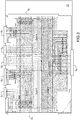
- the figure 3 illustrates a simplified electrical diagram of the principle of the interface box according to the invention.
- Zones 1 to 5 define zones which must be decoupled from each other electromagnetically. These decouplings are put in place to keep as much as possible the performance of the cables which connect to the DA1 and DA2 sockets of the two radios.
- the S1, S2, S4 and S7 metallic Ethernet sockets will have protection integrated into the integrated circuit PCB, against electromagnetic interference; three PCBs are used to connect the sockets and connect the flex cables for the transport of the signals.
- Zones 2, 3 and 4 which correspond to Ethernet and USB serial links, are particularly polluting zones. Their decoupling will be ensured by appropriate techniques known to those skilled in the art. Decoupling is taken into account in the case of a multilayer PCB by a particular arrangement of the tracks to be isolated, the lines of the switches of the interface box are decoupled by capacitors.
- the S1, S2, S4 and S7 Ethernet sockets have their pairs filtered by these RC cells (resistance-capacitance), not shown in the figure, at each of their ends.
- the values are, for example, with a resistance value of 3.3 ohms for the resistor and a capacitance value of 1.2 picofarads for the capacitance.
- the sockets have the functions described below:
- the DA1 base of the first radio station 41 is connected to the S1 base of the interface box according to the invention and the DA2 base of the second radio station 42 is connected to the S2 base of the interface box according to the invention when it is there are two radios or on the looping plug.
- the figure 4 illustrates a first example of interfacing of two radio stations, 41, 42 with a GPS 47 (Global Positioning System), an ERS-p 43 charger, a hardened tablet 45, a USB key, 46, and an adapter cord, a box control of the discrete 44, via the interface box according to the invention.
- GPS 47 Global Positioning System
- ERS-p 43 charger a hardened tablet 45
- USB key a USB key
- 46 an adapter cord
- the two radios 41, 42 are connected to the two sockets S1, S2, the ERS-p 43 charger is connected to the S4 socket, a discrete test box is connected to the S4 socket, the rugged tablet 45 is connected to the S1 base, the GPS 47 to the S2 base, and two USB keys 48 are connected respectively to the S5 base and to the S6 base.
- the interface box according to the invention makes it possible to dispense with the production of complex and fragile “specific hardened octopus” type cords and to be limited to the use of simple and robust cords with only two ends. Its fully passive electrical characteristics allow the performance of the transmission lines assigned to the different protocols to be preserved. It also offers the advantage in the case of a carrier more sensitive to EMC disturbances of being able to increase the filtering of the Ethernet lines.
Landscapes
- Engineering & Computer Science (AREA)
- Theoretical Computer Science (AREA)
- Computer Hardware Design (AREA)
- Human Computer Interaction (AREA)
- Physics & Mathematics (AREA)
- General Engineering & Computer Science (AREA)
- General Physics & Mathematics (AREA)
- Mobile Radio Communication Systems (AREA)
- Power Sources (AREA)
- Charge And Discharge Circuits For Batteries Or The Like (AREA)
Claims (3)
- Schnittstellengerät (20) zwischen mindestens einer Funkstation (41) und einer oder mehreren externen Ausrüstungen (44, 47), dadurch gekennzeichnet, dass es mindestens folgende Elemente umfasst:- einen ersten Sockel S1, welcher der ersten Funkstation (41) zugeordnet ist,- einen zweiten Sockel S2, welcher geeignet ist, die Verbindung zwischen der ersten Station und einer Geolokalisierungsvorrichtung sicherzustellen,- einen dritten Sockel S3, welcher geeignet ist, die Verbindung zwischen der ersten Funkstation und einem externen Ethernet-Peripheriegerät sicherzustellen,- einen vierten Sockel S4, welcher geeignet ist, eine Ethernet-Verbindung mit einem Ladegerät (4) sicherzustellen,- einen fünften Sockel S5, welcher geeignet ist, eine Verbindung mit einem USB-Peripheriegerät sicherzustellen,- einen sechsten Sockel S6, welcher geeignet ist, eine Verbindung mit einem USB-Peripheriegerät sicherzustellen,- einen achten Sockel S8, welcher geeignet ist, die Verbindung zwischen der ersten Funkstation und einer Testvorrichtung sicherzustellen, dadurch gekennzeichnet, dass er Folgendes umfasst:- einen siebten Sockel S7, welcher einer zweiten Funkstation (42) und der Verschleifung einer Ethernet-Verbindung der ersten Funkstation (41) mit einem Ethernet-Anschluss "EthA1/ B2" über einen zugeordneten Stopfen zugeordnet ist.
- Schnittstellengerät nach Anspruch 1, dadurch gekennzeichnet, dass die Sockel wie folgt zugewiesen sind:- der Sockel der Geolokalisierungsvorrichtung umfasst zwei Kontakte, welche TX-Sendesignalen, RX-Empfangssignalen einer RS232-Leitung zugewiesen sind und einen Kontakt, welcher einem PPS-Signal 1 zugewiesen ist und einen Kontakt, welcher der elektrischen Masse zugewiesen ist,- der Sockel des Ladegerätes umfasst vier Kontakte, welche zwei Paaren einer Ethernet-Leitung für den Kanal der ersten Funkstation (41) zugewiesen sind, einen Kontakt, welcher einem Signal zugewiesen ist, welches den Beibehalt der TOP_H_Cluster-Uhrzeit ermöglicht, vier weitere Kontakte für die elektrische Masse,- der Sockel S5 umfasst zwei Kontakte, welche einem Paar der seriellen Differenzial-Datenverbindung sind, einen Kontakt für die elektrische Masse und einen Kontakt für die Speisung eines USB-Peripheriegerätes,- wobei der Sockel S6 die gleichen Merkmale aufweist wie der Sockel S5,- der Ethernet-Sockel "EthA1/ B2" umfasst vier Kontakte, welche zwei Paaren einer Ethernet-Leitung für den Kanal A1 zugewiesen sind, einen Kontakt, welcher einem TOP_H_Cluster-Signal zugewiesen ist, vier Kontakte für die elektrische Masse,- der Verschleifungsstopfen ist in Abwesenheit einer zweiten Funkstation am Sockel S2 platziert,- die dem Ethernet zugewiesenen Kontaktpaare sind mit dem Kanal A1 der Ethernet-Leitung des Sockels S1 verbunden,- im Fall einer Verwendung mit zwei Funkstationen umfasst der Sockel S2 der zweiten Station vier Kontakte, welche den beiden Paaren einer Ethernet-Leitung für den aktiven Kanal B2 zugewiesen sind, in Abwesenheit der zweiten Funkstation und nach Aufbringen des Verschleifungsstopfens auf diesen Sockel,- der Sockel S8 "diskrete Auslagerung" umfasst einen Kontakt, welcher einem Ein-/Aus-Steuerbefehl einer Funkstation zugewiesen ist, vier Kontakte, welche einer Steuerung der "schwarzen diskreten" Plattform-Signale zugewiesen sind, einen Kontakt, welcher dem TOP_H_Cluster-Signal zugewiesen ist, einen Kontakt für die elektrische Masse.
- Schnittstellengerät nach Anspruch 1 oder 2, dadurch gekennzeichnet, dass die Sockel wie folgt zugewiesen sind:- der Sockel DA1 der ersten Funkstation (41) umfasst vier Kontakte, welche zwei Paaren eine Ethernet-Leitung für den Kanal A1 zugewiesen sind, welche über die Schnittstelle mit dem Kanal A2 des Sockels DA2 der zweiten Funkstation (42) verbunden sind,- der Sockel für die Geolokalisierungsvorrichtung umfasst zwei Kontakte, welche TX-Sendesignalen, RX-Empfangssignalen einer RS232-Leitung zugewiesen sind, einen Kontakt, welcher einem PPS-Signal 1 zugewiesen ist und einen Kontakt, welcher der elektrischen Masse zugewiesen ist,- der Sockel des Ladegerätes umfasst vier Kontakte, welche den zwei Paaren der Ethernet-Leitung für den Kanal B1 der ersten Station zugewiesen sind, einen Kontakt, welcher dem TOP_H_Cluster-Signal zugewiesen ist, vier Kontakte für die elektrische Masse,- der Sockel für eine erste USB-Verbindung umfasst zwei Kontakte, welche einem Paar der seriellen Differenzial-Datenverbindung zugewiesen sind, einen anderen Kontakt für die elektrische Masse und einen anderen für die Speisung des USB-Peripheriegerätes,- der Sockel für die zweite USB-Verbindung umfasst zwei Kontakte, welche einem Paar der seriellen Differenzial-Datenverbindung zugewiesen sind, und einen anderen Kontakt für die elektrische Masse und einen anderen für die Speisung des USB-Peripheriegerätes,- der Ethernet-Sockel "EthA1/ B2" umfasst vier Kontakte, welche zwei Paaren einer Ethernet-Leitung für den Kanal B2 zugewiesen sind, einen Kontakt, welcher dem TOP_H_Cluster-Signal zugewiesen ist, vier andere Kontakte für die elektrische Masse,- der Sockel DA2 der zweiten Funkstation umfasst vier Kontakte, welche den beiden Paaren eine Ethernet-Leitung für den Kanal A2 zugewiesen sind, welche über die Schnittstelle mit dem Kanal A1 des Sockels DA1 der ersten Funkstation (41) verbunden sind,- der Sockel "diskrete Auslagerung" umfasst einen Kontakt, welcher dem Ein-/Aus- Steuerbefehl der ersten und der zweiten Funkstation zugewiesen ist, vier Kontakte, welche der Steuerung der "diskreten schwarzen" Plattformsignale der ersten Funkstation und der zweiten Funkstation zugewiesen sind, einen Kontakt, welcher dem TOP_H_Cluster-Signal zugewiesen ist, einen Kontakt für die elektrische Masse.
Applications Claiming Priority (1)
| Application Number | Priority Date | Filing Date | Title |
|---|---|---|---|
| FR1874332A FR3091444B1 (fr) | 2018-12-28 | 2018-12-28 | Dispositif d'interface passif |
Publications (2)
| Publication Number | Publication Date |
|---|---|
| EP3674840A1 EP3674840A1 (de) | 2020-07-01 |
| EP3674840B1 true EP3674840B1 (de) | 2021-09-08 |
Family
ID=67383845
Family Applications (1)
| Application Number | Title | Priority Date | Filing Date |
|---|---|---|---|
| EP19219732.5A Active EP3674840B1 (de) | 2018-12-28 | 2019-12-26 | Passive schnittstellenvorrichtung |
Country Status (4)
| Country | Link |
|---|---|
| EP (1) | EP3674840B1 (de) |
| ES (1) | ES2902359T3 (de) |
| FR (1) | FR3091444B1 (de) |
| SG (1) | SG10201913544PA (de) |
Family Cites Families (1)
| Publication number | Priority date | Publication date | Assignee | Title |
|---|---|---|---|---|
| WO2011094703A1 (en) * | 2010-01-29 | 2011-08-04 | Certusview Technologies, Llc | Locating equipment docking station communicatively coupled to or equipped with a mobile/portable device |
-
2018
- 2018-12-28 FR FR1874332A patent/FR3091444B1/fr not_active Expired - Fee Related
-
2019
- 2019-12-26 EP EP19219732.5A patent/EP3674840B1/de active Active
- 2019-12-26 ES ES19219732T patent/ES2902359T3/es active Active
- 2019-12-27 SG SG10201913544PA patent/SG10201913544PA/en unknown
Also Published As
| Publication number | Publication date |
|---|---|
| EP3674840A1 (de) | 2020-07-01 |
| FR3091444A1 (fr) | 2020-07-03 |
| FR3091444B1 (fr) | 2022-03-11 |
| ES2902359T3 (es) | 2022-03-28 |
| SG10201913544PA (en) | 2020-07-29 |
Similar Documents
| Publication | Publication Date | Title |
|---|---|---|
| EP3818639B1 (de) | Entwurf für daten-über-stromleitung | |
| EP0720292B1 (de) | Mobilfunkendgerät mit einem Schaltkreis | |
| FR2818454A1 (fr) | Protection pour reseau electrique ayant une liaison radio courte distance dite "bluetooth" | |
| CA2842254C (en) | Audio signal adapter device and system for transmitting audio signal | |
| EP3674840B1 (de) | Passive schnittstellenvorrichtung | |
| EP1134958B1 (de) | Mobiltelefon mit multifunktionalem Steckverbinder | |
| EP3716130B1 (de) | Elektronisches system | |
| EP3716118A1 (de) | Elektronisches system | |
| EP3716117A1 (de) | Elektronisches system | |
| FR2812981A1 (fr) | Protection pour reseau electrique ayant une liaison de transmission de donnees infrarouge utilisant le protocole wap | |
| EP0962869B1 (de) | Zwei-Standard-Schnittstellenschaltung für serielle Verbindung | |
| FR3061340B1 (fr) | Dispositif multifrequence, dispositif de commande et/ou de controle, equipement domotique et systeme multifrequence associe | |
| EP3723002B1 (de) | Elektronischer chip mit kommunikationsschnittstellen | |
| EP2678942A1 (de) | Vorrichtung und verfahren zur vernetzung elektronischer systeme mit verschiedenen referenzpotentialen | |
| FR2878376A1 (fr) | Connecteur unique pour radiotelephone, circuit electronique, radiotelephone et cable correspondants | |
| WO2018007742A1 (fr) | Dispositif de communication modulaire | |
| EP2936448A1 (de) | Vorrichtung und verbindungsstecker zum austausch von fahrzeugdaten | |
| FR3050086A1 (fr) | Reseau de communication embarque d'un aeronef et systeme de communication | |
| CN113645167B (zh) | 传输数字音频和电源信号的方法、系统、设备及存储介质 | |
| EP1059706B1 (de) | Anschlussvorrichtung für elektronische Einheiten oder Module | |
| WO2006010657A1 (fr) | Connecteur unique pour terminal de communication, circuit electronique, terminal et cable correspondants | |
| EP3376823B1 (de) | Kommunikationsvorrichtung | |
| BE1001402A3 (fr) | Dispositif de transmission et de reception de signaux de telecommande. | |
| EP1889084B8 (de) | Module zum testen der elektromagnetischen verträglichkeit einer hochgeschwindigkeits-ethernetschnittstelle an bord eines flugzeugs | |
| CN202145652U (zh) | 移动通信装置 |
Legal Events
| Date | Code | Title | Description |
|---|---|---|---|
| PUAI | Public reference made under article 153(3) epc to a published international application that has entered the european phase |
Free format text: ORIGINAL CODE: 0009012 |
|
| STAA | Information on the status of an ep patent application or granted ep patent |
Free format text: STATUS: THE APPLICATION HAS BEEN PUBLISHED |
|
| AK | Designated contracting states |
Kind code of ref document: A1 Designated state(s): AL AT BE BG CH CY CZ DE DK EE ES FI FR GB GR HR HU IE IS IT LI LT LU LV MC MK MT NL NO PL PT RO RS SE SI SK SM TR |
|
| AX | Request for extension of the european patent |
Extension state: BA ME |
|
| STAA | Information on the status of an ep patent application or granted ep patent |
Free format text: STATUS: REQUEST FOR EXAMINATION WAS MADE |
|
| 17P | Request for examination filed |
Effective date: 20201229 |
|
| RBV | Designated contracting states (corrected) |
Designated state(s): AL AT BE BG CH CY CZ DE DK EE ES FI FR GB GR HR HU IE IS IT LI LT LU LV MC MK MT NL NO PL PT RO RS SE SI SK SM TR |
|
| GRAP | Despatch of communication of intention to grant a patent |
Free format text: ORIGINAL CODE: EPIDOSNIGR1 |
|
| STAA | Information on the status of an ep patent application or granted ep patent |
Free format text: STATUS: GRANT OF PATENT IS INTENDED |
|
| INTG | Intention to grant announced |
Effective date: 20210607 |
|
| GRAS | Grant fee paid |
Free format text: ORIGINAL CODE: EPIDOSNIGR3 |
|
| GRAA | (expected) grant |
Free format text: ORIGINAL CODE: 0009210 |
|
| STAA | Information on the status of an ep patent application or granted ep patent |
Free format text: STATUS: THE PATENT HAS BEEN GRANTED |
|
| AK | Designated contracting states |
Kind code of ref document: B1 Designated state(s): AL AT BE BG CH CY CZ DE DK EE ES FI FR GB GR HR HU IE IS IT LI LT LU LV MC MK MT NL NO PL PT RO RS SE SI SK SM TR |
|
| REG | Reference to a national code |
Ref country code: GB Ref legal event code: FG4D Free format text: NOT ENGLISH |
|
| REG | Reference to a national code |
Ref country code: CH Ref legal event code: EP Ref country code: AT Ref legal event code: REF Ref document number: 1429155 Country of ref document: AT Kind code of ref document: T Effective date: 20210915 |
|
| REG | Reference to a national code |
Ref country code: IE Ref legal event code: FG4D Free format text: LANGUAGE OF EP DOCUMENT: FRENCH |
|
| REG | Reference to a national code |
Ref country code: DE Ref legal event code: R096 Ref document number: 602019007563 Country of ref document: DE |
|
| REG | Reference to a national code |
Ref country code: FI Ref legal event code: FGE |
|
| REG | Reference to a national code |
Ref country code: LT Ref legal event code: MG9D |
|
| REG | Reference to a national code |
Ref country code: NL Ref legal event code: FP |
|
| PG25 | Lapsed in a contracting state [announced via postgrant information from national office to epo] |
Ref country code: BG Free format text: LAPSE BECAUSE OF FAILURE TO SUBMIT A TRANSLATION OF THE DESCRIPTION OR TO PAY THE FEE WITHIN THE PRESCRIBED TIME-LIMIT Effective date: 20211208 Ref country code: LT Free format text: LAPSE BECAUSE OF FAILURE TO SUBMIT A TRANSLATION OF THE DESCRIPTION OR TO PAY THE FEE WITHIN THE PRESCRIBED TIME-LIMIT Effective date: 20210908 Ref country code: NO Free format text: LAPSE BECAUSE OF FAILURE TO SUBMIT A TRANSLATION OF THE DESCRIPTION OR TO PAY THE FEE WITHIN THE PRESCRIBED TIME-LIMIT Effective date: 20211208 Ref country code: HR Free format text: LAPSE BECAUSE OF FAILURE TO SUBMIT A TRANSLATION OF THE DESCRIPTION OR TO PAY THE FEE WITHIN THE PRESCRIBED TIME-LIMIT Effective date: 20210908 Ref country code: RS Free format text: LAPSE BECAUSE OF FAILURE TO SUBMIT A TRANSLATION OF THE DESCRIPTION OR TO PAY THE FEE WITHIN THE PRESCRIBED TIME-LIMIT Effective date: 20210908 Ref country code: SE Free format text: LAPSE BECAUSE OF FAILURE TO SUBMIT A TRANSLATION OF THE DESCRIPTION OR TO PAY THE FEE WITHIN THE PRESCRIBED TIME-LIMIT Effective date: 20210908 |
|
| REG | Reference to a national code |
Ref country code: GR Ref legal event code: EP Ref document number: 20210403217 Country of ref document: GR Effective date: 20220113 |
|
| REG | Reference to a national code |
Ref country code: AT Ref legal event code: MK05 Ref document number: 1429155 Country of ref document: AT Kind code of ref document: T Effective date: 20210908 |
|
| PG25 | Lapsed in a contracting state [announced via postgrant information from national office to epo] |
Ref country code: LV Free format text: LAPSE BECAUSE OF FAILURE TO SUBMIT A TRANSLATION OF THE DESCRIPTION OR TO PAY THE FEE WITHIN THE PRESCRIBED TIME-LIMIT Effective date: 20210908 |
|
| REG | Reference to a national code |
Ref country code: ES Ref legal event code: FG2A Ref document number: 2902359 Country of ref document: ES Kind code of ref document: T3 Effective date: 20220328 |
|
| PG25 | Lapsed in a contracting state [announced via postgrant information from national office to epo] |
Ref country code: AT Free format text: LAPSE BECAUSE OF FAILURE TO SUBMIT A TRANSLATION OF THE DESCRIPTION OR TO PAY THE FEE WITHIN THE PRESCRIBED TIME-LIMIT Effective date: 20210908 |
|
| PG25 | Lapsed in a contracting state [announced via postgrant information from national office to epo] |
Ref country code: IS Free format text: LAPSE BECAUSE OF FAILURE TO SUBMIT A TRANSLATION OF THE DESCRIPTION OR TO PAY THE FEE WITHIN THE PRESCRIBED TIME-LIMIT Effective date: 20220108 Ref country code: SM Free format text: LAPSE BECAUSE OF FAILURE TO SUBMIT A TRANSLATION OF THE DESCRIPTION OR TO PAY THE FEE WITHIN THE PRESCRIBED TIME-LIMIT Effective date: 20210908 Ref country code: SK Free format text: LAPSE BECAUSE OF FAILURE TO SUBMIT A TRANSLATION OF THE DESCRIPTION OR TO PAY THE FEE WITHIN THE PRESCRIBED TIME-LIMIT Effective date: 20210908 Ref country code: RO Free format text: LAPSE BECAUSE OF FAILURE TO SUBMIT A TRANSLATION OF THE DESCRIPTION OR TO PAY THE FEE WITHIN THE PRESCRIBED TIME-LIMIT Effective date: 20210908 Ref country code: PT Free format text: LAPSE BECAUSE OF FAILURE TO SUBMIT A TRANSLATION OF THE DESCRIPTION OR TO PAY THE FEE WITHIN THE PRESCRIBED TIME-LIMIT Effective date: 20220110 Ref country code: PL Free format text: LAPSE BECAUSE OF FAILURE TO SUBMIT A TRANSLATION OF THE DESCRIPTION OR TO PAY THE FEE WITHIN THE PRESCRIBED TIME-LIMIT Effective date: 20210908 Ref country code: EE Free format text: LAPSE BECAUSE OF FAILURE TO SUBMIT A TRANSLATION OF THE DESCRIPTION OR TO PAY THE FEE WITHIN THE PRESCRIBED TIME-LIMIT Effective date: 20210908 Ref country code: CZ Free format text: LAPSE BECAUSE OF FAILURE TO SUBMIT A TRANSLATION OF THE DESCRIPTION OR TO PAY THE FEE WITHIN THE PRESCRIBED TIME-LIMIT Effective date: 20210908 Ref country code: AL Free format text: LAPSE BECAUSE OF FAILURE TO SUBMIT A TRANSLATION OF THE DESCRIPTION OR TO PAY THE FEE WITHIN THE PRESCRIBED TIME-LIMIT Effective date: 20210908 |
|
| REG | Reference to a national code |
Ref country code: DE Ref legal event code: R097 Ref document number: 602019007563 Country of ref document: DE |
|
| PLBE | No opposition filed within time limit |
Free format text: ORIGINAL CODE: 0009261 |
|
| STAA | Information on the status of an ep patent application or granted ep patent |
Free format text: STATUS: NO OPPOSITION FILED WITHIN TIME LIMIT |
|
| PG25 | Lapsed in a contracting state [announced via postgrant information from national office to epo] |
Ref country code: MC Free format text: LAPSE BECAUSE OF FAILURE TO SUBMIT A TRANSLATION OF THE DESCRIPTION OR TO PAY THE FEE WITHIN THE PRESCRIBED TIME-LIMIT Effective date: 20210908 Ref country code: DK Free format text: LAPSE BECAUSE OF FAILURE TO SUBMIT A TRANSLATION OF THE DESCRIPTION OR TO PAY THE FEE WITHIN THE PRESCRIBED TIME-LIMIT Effective date: 20210908 |
|
| 26N | No opposition filed |
Effective date: 20220609 |
|
| PG25 | Lapsed in a contracting state [announced via postgrant information from national office to epo] |
Ref country code: SI Free format text: LAPSE BECAUSE OF FAILURE TO SUBMIT A TRANSLATION OF THE DESCRIPTION OR TO PAY THE FEE WITHIN THE PRESCRIBED TIME-LIMIT Effective date: 20210908 |
|
| PG25 | Lapsed in a contracting state [announced via postgrant information from national office to epo] |
Ref country code: IE Free format text: LAPSE BECAUSE OF NON-PAYMENT OF DUE FEES Effective date: 20211226 |
|
| P01 | Opt-out of the competence of the unified patent court (upc) registered |
Effective date: 20230516 |
|
| PG25 | Lapsed in a contracting state [announced via postgrant information from national office to epo] |
Ref country code: CY Free format text: LAPSE BECAUSE OF FAILURE TO SUBMIT A TRANSLATION OF THE DESCRIPTION OR TO PAY THE FEE WITHIN THE PRESCRIBED TIME-LIMIT Effective date: 20210908 |
|
| PG25 | Lapsed in a contracting state [announced via postgrant information from national office to epo] |
Ref country code: HU Free format text: LAPSE BECAUSE OF FAILURE TO SUBMIT A TRANSLATION OF THE DESCRIPTION OR TO PAY THE FEE WITHIN THE PRESCRIBED TIME-LIMIT; INVALID AB INITIO Effective date: 20191226 |
|
| PG25 | Lapsed in a contracting state [announced via postgrant information from national office to epo] |
Ref country code: MK Free format text: LAPSE BECAUSE OF FAILURE TO SUBMIT A TRANSLATION OF THE DESCRIPTION OR TO PAY THE FEE WITHIN THE PRESCRIBED TIME-LIMIT Effective date: 20210908 |
|
| GBPC | Gb: european patent ceased through non-payment of renewal fee |
Effective date: 20231226 |
|
| PG25 | Lapsed in a contracting state [announced via postgrant information from national office to epo] |
Ref country code: MT Free format text: LAPSE BECAUSE OF FAILURE TO SUBMIT A TRANSLATION OF THE DESCRIPTION OR TO PAY THE FEE WITHIN THE PRESCRIBED TIME-LIMIT Effective date: 20210908 |
|
| PG25 | Lapsed in a contracting state [announced via postgrant information from national office to epo] |
Ref country code: GB Free format text: LAPSE BECAUSE OF NON-PAYMENT OF DUE FEES Effective date: 20231226 |
|
| PG25 | Lapsed in a contracting state [announced via postgrant information from national office to epo] |
Ref country code: GB Free format text: LAPSE BECAUSE OF NON-PAYMENT OF DUE FEES Effective date: 20231226 |
|
| PG25 | Lapsed in a contracting state [announced via postgrant information from national office to epo] |
Ref country code: TR Free format text: LAPSE BECAUSE OF FAILURE TO SUBMIT A TRANSLATION OF THE DESCRIPTION OR TO PAY THE FEE WITHIN THE PRESCRIBED TIME-LIMIT Effective date: 20210908 |
|
| PGFP | Annual fee paid to national office [announced via postgrant information from national office to epo] |
Ref country code: NL Payment date: 20251126 Year of fee payment: 7 |
|
| REG | Reference to a national code |
Ref country code: CH Ref legal event code: U11 Free format text: ST27 STATUS EVENT CODE: U-0-0-U10-U11 (AS PROVIDED BY THE NATIONAL OFFICE) Effective date: 20260101 |
|
| PGFP | Annual fee paid to national office [announced via postgrant information from national office to epo] |
Ref country code: DE Payment date: 20251119 Year of fee payment: 7 |
|
| PGFP | Annual fee paid to national office [announced via postgrant information from national office to epo] |
Ref country code: IT Payment date: 20251126 Year of fee payment: 7 Ref country code: FI Payment date: 20251211 Year of fee payment: 7 |
|
| PGFP | Annual fee paid to national office [announced via postgrant information from national office to epo] |
Ref country code: LU Payment date: 20251215 Year of fee payment: 7 Ref country code: FR Payment date: 20251124 Year of fee payment: 7 |
|
| PGFP | Annual fee paid to national office [announced via postgrant information from national office to epo] |
Ref country code: GR Payment date: 20251128 Year of fee payment: 7 Ref country code: BE Payment date: 20251117 Year of fee payment: 7 |
|
| PGFP | Annual fee paid to national office [announced via postgrant information from national office to epo] |
Ref country code: ES Payment date: 20260114 Year of fee payment: 7 |
|
| PGFP | Annual fee paid to national office [announced via postgrant information from national office to epo] |
Ref country code: CH Payment date: 20260101 Year of fee payment: 7 |