EP3674825A1 - Work assistance system - Google Patents
Work assistance system Download PDFInfo
- Publication number
- EP3674825A1 EP3674825A1 EP18847421.7A EP18847421A EP3674825A1 EP 3674825 A1 EP3674825 A1 EP 3674825A1 EP 18847421 A EP18847421 A EP 18847421A EP 3674825 A1 EP3674825 A1 EP 3674825A1
- Authority
- EP
- European Patent Office
- Prior art keywords
- unit
- display
- processing apparatus
- captured
- worker
- Prior art date
- Legal status (The legal status is an assumption and is not a legal conclusion. Google has not performed a legal analysis and makes no representation as to the accuracy of the status listed.)
- Withdrawn
Links
Images



Classifications
-
- G—PHYSICS
- G05—CONTROLLING; REGULATING
- G05B—CONTROL OR REGULATING SYSTEMS IN GENERAL; FUNCTIONAL ELEMENTS OF SUCH SYSTEMS; MONITORING OR TESTING ARRANGEMENTS FOR SUCH SYSTEMS OR ELEMENTS
- G05B19/00—Program-control systems
- G05B19/02—Program-control systems electric
- G05B19/18—Numerical control [NC], i.e. automatically operating machines, in particular machine tools, e.g. in a manufacturing environment, so as to execute positioning, movement or co-ordinated operations by means of program data in numerical form
- G05B19/409—Numerical control [NC], i.e. automatically operating machines, in particular machine tools, e.g. in a manufacturing environment, so as to execute positioning, movement or co-ordinated operations by means of program data in numerical form characterised by using manual data input [MDI] or by using control panel, e.g. controlling functions with the panel; characterised by control panel details or by setting parameters
-
- G—PHYSICS
- G05—CONTROLLING; REGULATING
- G05B—CONTROL OR REGULATING SYSTEMS IN GENERAL; FUNCTIONAL ELEMENTS OF SUCH SYSTEMS; MONITORING OR TESTING ARRANGEMENTS FOR SUCH SYSTEMS OR ELEMENTS
- G05B19/00—Program-control systems
- G05B19/02—Program-control systems electric
- G05B19/418—Total factory control, i.e. centrally controlling a plurality of machines, e.g. direct or distributed numerical control [DNC], flexible manufacturing systems [FMS], integrated manufacturing systems [IMS] or computer integrated manufacturing [CIM]
-
- G—PHYSICS
- G06—COMPUTING OR CALCULATING; COUNTING
- G06F—ELECTRIC DIGITAL DATA PROCESSING
- G06F3/00—Input arrangements for transferring data to be processed into a form capable of being handled by the computer; Output arrangements for transferring data from processing unit to output unit, e.g. interface arrangements
- G06F3/01—Input arrangements or combined input and output arrangements for interaction between user and computer
-
- G—PHYSICS
- G06—COMPUTING OR CALCULATING; COUNTING
- G06F—ELECTRIC DIGITAL DATA PROCESSING
- G06F3/00—Input arrangements for transferring data to be processed into a form capable of being handled by the computer; Output arrangements for transferring data from processing unit to output unit, e.g. interface arrangements
- G06F3/01—Input arrangements or combined input and output arrangements for interaction between user and computer
- G06F3/011—Arrangements for interaction with the human body, e.g. for user immersion in virtual reality
- G06F3/012—Head tracking input arrangements
-
- G—PHYSICS
- G06—COMPUTING OR CALCULATING; COUNTING
- G06F—ELECTRIC DIGITAL DATA PROCESSING
- G06F3/00—Input arrangements for transferring data to be processed into a form capable of being handled by the computer; Output arrangements for transferring data from processing unit to output unit, e.g. interface arrangements
- G06F3/01—Input arrangements or combined input and output arrangements for interaction between user and computer
- G06F3/048—Interaction techniques based on graphical user interfaces [GUI]
- G06F3/0481—Interaction techniques based on graphical user interfaces [GUI] based on specific properties of the displayed interaction object or a metaphor-based environment, e.g. interaction with desktop elements like windows or icons, or assisted by a cursor's changing behaviour or appearance
-
- G—PHYSICS
- G06—COMPUTING OR CALCULATING; COUNTING
- G06F—ELECTRIC DIGITAL DATA PROCESSING
- G06F3/00—Input arrangements for transferring data to be processed into a form capable of being handled by the computer; Output arrangements for transferring data from processing unit to output unit, e.g. interface arrangements
- G06F3/01—Input arrangements or combined input and output arrangements for interaction between user and computer
- G06F3/048—Interaction techniques based on graphical user interfaces [GUI]
- G06F3/0481—Interaction techniques based on graphical user interfaces [GUI] based on specific properties of the displayed interaction object or a metaphor-based environment, e.g. interaction with desktop elements like windows or icons, or assisted by a cursor's changing behaviour or appearance
- G06F3/0482—Interaction with lists of selectable items, e.g. menus
-
- G—PHYSICS
- G06—COMPUTING OR CALCULATING; COUNTING
- G06F—ELECTRIC DIGITAL DATA PROCESSING
- G06F3/00—Input arrangements for transferring data to be processed into a form capable of being handled by the computer; Output arrangements for transferring data from processing unit to output unit, e.g. interface arrangements
- G06F3/01—Input arrangements or combined input and output arrangements for interaction between user and computer
- G06F3/048—Interaction techniques based on graphical user interfaces [GUI]
- G06F3/0484—Interaction techniques based on graphical user interfaces [GUI] for the control of specific functions or operations, e.g. selecting or manipulating an object, an image or a displayed text element, setting a parameter value or selecting a range
- G06F3/04847—Interaction techniques to control parameter settings, e.g. interaction with sliders or dials
-
- G—PHYSICS
- G06—COMPUTING OR CALCULATING; COUNTING
- G06F—ELECTRIC DIGITAL DATA PROCESSING
- G06F3/00—Input arrangements for transferring data to be processed into a form capable of being handled by the computer; Output arrangements for transferring data from processing unit to output unit, e.g. interface arrangements
- G06F3/14—Digital output to display device ; Cooperation and interconnection of the display device with other functional units
-
- G—PHYSICS
- G06—COMPUTING OR CALCULATING; COUNTING
- G06Q—INFORMATION AND COMMUNICATION TECHNOLOGY [ICT] SPECIALLY ADAPTED FOR ADMINISTRATIVE, COMMERCIAL, FINANCIAL, MANAGERIAL OR SUPERVISORY PURPOSES; SYSTEMS OR METHODS SPECIALLY ADAPTED FOR ADMINISTRATIVE, COMMERCIAL, FINANCIAL, MANAGERIAL OR SUPERVISORY PURPOSES, NOT OTHERWISE PROVIDED FOR
- G06Q50/00—Information and communication technology [ICT] specially adapted for implementation of business processes of specific business sectors, e.g. utilities or tourism
- G06Q50/04—Manufacturing
-
- G—PHYSICS
- G06—COMPUTING OR CALCULATING; COUNTING
- G06T—IMAGE DATA PROCESSING OR GENERATION, IN GENERAL
- G06T7/00—Image analysis
- G06T7/70—Determining position or orientation of objects or cameras
-
- H—ELECTRICITY
- H04—ELECTRIC COMMUNICATION TECHNIQUE
- H04N—PICTORIAL COMMUNICATION, e.g. TELEVISION
- H04N5/00—Details of television systems
- H04N5/222—Studio circuitry; Studio devices; Studio equipment
- H04N5/262—Studio circuits, e.g. for mixing, switching-over, change of character of image, other special effects ; Cameras specially adapted for the electronic generation of special effects
- H04N5/272—Means for inserting a foreground image in a background image, i.e. inlay, outlay
-
- G—PHYSICS
- G05—CONTROLLING; REGULATING
- G05B—CONTROL OR REGULATING SYSTEMS IN GENERAL; FUNCTIONAL ELEMENTS OF SUCH SYSTEMS; MONITORING OR TESTING ARRANGEMENTS FOR SUCH SYSTEMS OR ELEMENTS
- G05B2219/00—Program-control systems
- G05B2219/30—Nc systems
- G05B2219/32—Operator till task planning
- G05B2219/32014—Augmented reality assists operator in maintenance, repair, programming, assembly, use of head mounted display with 2-D 3-D display and voice feedback, voice and gesture command
-
- G—PHYSICS
- G06—COMPUTING OR CALCULATING; COUNTING
- G06T—IMAGE DATA PROCESSING OR GENERATION, IN GENERAL
- G06T2207/00—Indexing scheme for image analysis or image enhancement
- G06T2207/30—Subject of image; Context of image processing
- G06T2207/30108—Industrial image inspection
-
- H—ELECTRICITY
- H04—ELECTRIC COMMUNICATION TECHNIQUE
- H04N—PICTORIAL COMMUNICATION, e.g. TELEVISION
- H04N23/00—Cameras or camera modules comprising electronic image sensors; Control thereof
- H04N23/57—Mechanical or electrical details of cameras or camera modules specially adapted for being embedded in other devices
-
- Y—GENERAL TAGGING OF NEW TECHNOLOGICAL DEVELOPMENTS; GENERAL TAGGING OF CROSS-SECTIONAL TECHNOLOGIES SPANNING OVER SEVERAL SECTIONS OF THE IPC; TECHNICAL SUBJECTS COVERED BY FORMER USPC CROSS-REFERENCE ART COLLECTIONS [XRACs] AND DIGESTS
- Y02—TECHNOLOGIES OR APPLICATIONS FOR MITIGATION OR ADAPTATION AGAINST CLIMATE CHANGE
- Y02P—CLIMATE CHANGE MITIGATION TECHNOLOGIES IN THE PRODUCTION OR PROCESSING OF GOODS
- Y02P90/00—Enabling technologies with a potential contribution to greenhouse gas [GHG] emissions mitigation
- Y02P90/30—Computing systems specially adapted for manufacturing
Definitions
- An aspect of the present disclosure relates to a work assistance system.
- Patent Literature 1 discloses a work assistance system that displays additional information such as work explanatory information on a work target through an image display unit in the shape of eyeglasses disposed in front of the worker's eyes to cover the worker's field of vision.
- Patent Literature 1 Japanese Unexamined Patent Publication No. 2016-208331
- Such a system can provide workers with various information. However, there is a room for improvement in various points in order to improve the work efficiency of workers.
- An aspect of the present disclosure therefore is to provide a work assistance system that can improve the work efficiency of workers.
- a work assistance system assists a worker working in a factory equipped with a plurality of processing apparatuses.
- the work assistance system includes a display unit having portability and configured to display information provided to the worker, an imaging unit having portability and configured to capture an image of the processing apparatus, a display controller configured to control a content of information displayed on the display unit, and an identifying unit configured to identify from which direction the processing apparatus is captured by the imaging unit, based on data captured by the imaging unit.
- the display controller causes the display unit to display an adjustment screen for adjusting an operation parameter of the processing apparatus captured by the imaging unit.
- information suitable for a state is provided to the worker, based on the assumption that in a state in which the worker wishes to adjust the operation of one processing apparatus, the worker would view the processing apparatus from a particular one direction.
- information to be provided to the worker can be provided at an appropriate timing based on the state of the worker. As a result, the work efficiency of the worker can be improved.
- the display unit may display a real space in the factory and the adjustment screen so as to overlap each other.
- the processing apparatus and the adjustment screen for adjusting an operation parameter in the processing apparatus are displayed in an overlapped state.
- the work assistance system may further include an input unit configured to input the operation parameter in the adjustment screen and a communication unit configured to transmit the operation parameter input through the input unit to the processing apparatus.
- the operation parameter of the processing apparatus can be changed through the display unit having portability, the input unit, and the communication unit. This configuration enables the worker to adjust the processing apparatus more efficiently.
- the display controller may allow the adjustment screen to be displayed only when the direction identified by the identifying unit is a predetermined direction.
- the work assistance system having this configuration prevents the adjustment screen from appearing on the display unit with easy operation and therefore prevents the setting of the processing apparatus from being changed carelessly.
- the display controller may cause the display unit to display the adjustment screen corresponding to the processing apparatus captured by the imaging unit, and when the direction identified by the identifying unit is a direction other than the predetermined direction, the display controller may cause the display unit to display an operating status display screen displaying an operating status of the processing apparatus captured by the imaging unit.
- information suitable for a state is provided to the worker, based on the assumption that in a state in which the worker wishes to adjust the operation of one processing apparatus, the worker would view the processing apparatus from a particular one direction, and in a state in which the worker wishes to check the state of one processing apparatus, the worker would view the processing apparatus from a different direction.
- information to be provided to the worker can be switched at an appropriate timing based on the state of the worker. As a result, the work efficiency of the worker can be improved.
- the display controller may display the adjustment screen only corresponding to the part captured by the imaging unit on the display unit.
- a screen appears that enables adjustment of only the operation parameter of the part assumed to be viewed by the worker. As a result, only the minimum information required by the worker is provided, and adjustment of an unintended part can be prevented.
- the processing apparatus may be a combination weighing apparatus configured to combination-weigh an article externally charged and supply the combination-weighed article to another processing apparatus disposed on a downstream side.
- the display controller may allow the adjustment screen of the combination weighing apparatus to be displayed.
- information suitable for a state is provided to the worker, based on the assumption that in a state in which the worker wishes to check the state of one combination weighing apparatus, the worker would view so as to look up the one combination weighing apparatus from the lower direction.
- information to be provided to the worker the adjustment screen for the operation parameter of the combination weighing apparatus or the operating status display screen of the combination weighing apparatus
- the work efficiency of the worker can be improved.
- the work efficiency of workers can be improved.
- a work assistance system 1 in the present embodiment is a system that assists workers who work in a factory equipped with a plurality of processing apparatuses.
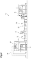
- the work assistance system 1 used in a factory equipped with a production line 30 including a conveyance apparatus 35, a combination weighing apparatus 40, a bag-making and packing apparatus 70, a seal inspection apparatus 75, an X-ray inspection apparatus 80, a metal detector 85, a weight checking apparatus 90, and a case packing apparatus 95 as processing apparatuses as illustrated in FIG. 2 is described by way of example.
- the conveyance apparatus 35 is an apparatus that conveys an article A (see FIG. 3 ) from a supply unit to the combination weighing apparatus 40 and supplies the article A to an input chute 42 of the combination weighing apparatus 40.
- the combination weighing apparatus 40 is an apparatus that weighs out a predetermined amount of the article A.
- the bag-making and packing apparatus 70 is an apparatus that packs the article A weighed out by the combination weighing apparatus 40 while making a bag for packing the article A.
- the seal inspection apparatus 75 is an apparatus that detects abnormality of a bag made and packed by the bag-making and packing apparatus 70.
- the X-ray inspection apparatus 80 is an apparatus that inspects the state of the article A contained in a bag or inclusion of a foreign matter.
- the metal detector 85 is an apparatus that inspects the article A contained in a bag for inclusion of metal.
- the weight checking apparatus 90 is an apparatus that checks the weight of a commodity containing the article A.
- the case packing apparatus 95 is an apparatus that packs a commodity into a cardboard box.
- the work assistance system 1 includes a portable head mount display (hereinafter referred to as "HMD") 10 in the shape of eyeglasses and a management server 20.
- the HMD 10 has a display unit 11, an imaging unit 15, an input unit 16, and a communication unit 17.
- the display unit 11 displays information provided to the worker.
- the display unit 11 displays (superimposes) the real space in the factory and information provided to the worker so as to overlap each other. Superimposition on the display unit 11 is implemented, for example, by configuring the display unit 11 with a half mirror or by projecting an image captured by the imaging unit 15 onto the display unit 11.
- the imaging unit 15 captures an image of the real space in a factory.
- the imaging unit 15 is provided such that the real space viewed by the worker wearing the HMD 10 generally matches the real space captured by the imaging unit 15. That is, the imaging unit 15 is a vision synchronous camera that captures a front view image in the eye direction of the worker.
- the imaging unit 15 causes the display unit 11 to display the captured data.
- the imaging unit 15 also transmits the captured data to the management server 20.
- the input unit 16 includes keys to select up, down, left, and right and a key to confirm an entry.
- the worker can operate the input unit 16 to select a menu appearing on the display unit 11 or confirm a menu.
- the communication unit 17 is an interface for exchanging data with the management server 20. Communication with the management server 20 may be wireless or wired.
- the management server 20 is configured as a computer system including a central processing unit (CPU), a main memory such as a random access memory (RAM) and a read only memory (ROM), an auxiliary storage such as a hard disk and a flash memory, an input unit such as a keyboard and a mouse, and an output unit such as a display screen.
- CPU central processing unit
- main memory such as a random access memory (RAM) and a read only memory (ROM)
- auxiliary storage such as a hard disk and a flash memory
- an input unit such as a keyboard and a mouse
- an output unit such as a display screen.
- the management server 20 is connected to communicate with each of the conveyance apparatus 35, the combination weighing apparatus 40, the bag-making and packing apparatus 70, the seal inspection apparatus 75, the X-ray inspection apparatus 80, the metal detector 85, the weight checking apparatus 90, and the case packing apparatus 95 through a communication unit 21.
- the management server 20 and each processing apparatus may be connected wirelessly or may be connected by wire.
- the management server 20 can control the operation of the processing apparatuses included in the production line 30.
- the management server 20 is also connected to communicate with the HMD 10 through the communication unit 21.
- the identifying unit 22 identifies from which direction one processing apparatus is captured by the imaging unit 15, based on data on the one processing apparatus captured by the imaging unit 15. In the present embodiment, from which direction “up”, “down”, “left”, or “right” one processing apparatus is captured by the imaging unit 15 is identified.
- the capturing direction may be identified by matching the captured image with an image stored in advance or may be identified using information such as position, altitude (height), and direction, if a sensor capable of acquiring such information is installed in the HMD 10.
- the display controller 23 controls the content of information appearing on the display unit 11 of the HMD 10.
- the display controller 23 causes the display unit 11 to display an adjustment screen for adjusting an operation parameter of the one processing apparatus.
- the display controller 23 in the present embodiment causes the display unit 11 to display an adjustment screen 12B (see FIG. 7(B) ) for adjusting an operation parameter of the one processing apparatus.
- the display controller 23 in the present embodiment causes the display unit 11 to display an operating status display screen 12A (see FIG. 7(A) ) that displays information about the operating status of the operation parameter of the one processing apparatus.
- the display controller 23 causes the display unit 11 to display the adjustment screen 12B (see FIG. 7(B) ) of the combination weighing apparatus 40.
- the display controller 23 causes the display unit 11 to display the operating status display screen 12A (see FIG. 7(A) ) of the combination weighing apparatus 40.
- the combination weighing apparatus 40 which is one processing apparatus in the production line 30 will now be described in detail, and the timing at which the operating status display screen 12A and the adjustment screen 12B for the combination weighing apparatus 40 are distributed from the work assistance system 1 to the HMD 10 will be described.
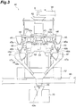
- the combination weighing apparatus 40 includes an input chute 42, a distributing table 43, a plurality of radial feeders 44, a plurality of pool hoppers 45, a plurality of weighing hoppers 46, a plurality of booster hoppers 47, a collecting chute 48, a timing hopper 49, a weighing unit 51, and a controller 60.
- the combination weighing apparatus 40 weighs the article A supplied by the conveyance apparatus 35 at a target weight value and supplies the weighed article A to the bag-making and packing apparatus 70.
- the article A is an article that varies in individual mass, such as agricultural products, fishery products, and processed food products.
- the bag-making and packing apparatus 70 bags the article weighed and supplied by the combination weighing apparatus 40 while shaping a film into a bag with a predetermined capacity.
- the input chute 42 is arranged below a conveyance end of the conveyance apparatus 35.
- the input chute 42 is a tubular member having an inner hollow portion with openings above and below.
- the article A dropping from the conveyance end of the conveyance apparatus 35 is charged into the inner hollow portion of the input chute 42.
- the article A dropped into the inner hollow portion is discharged to the distributing table 43 through the opening below.
- the distributing table 43 is disposed below the input chute 42.
- the distributing table 43 has a conical conveyance surface 43a expanding downward.
- the distributing table 43 rotates the conveyance surface 43a to convey the article A discharged from the input chute 42 to the apex portion of the conveyance surface 43a uniformly toward the outer edge of the conveyance surface 43a.
- a driver 55 rotates the distributing table 43 about the center portion of the distributing table 43.
- An example of the driver 55 is a motor.
- the driver 55 intermittently rotates the distributing table 43. That is, the distributing table 43 repeats rotating and stopping.
- a plurality of radial feeders 44 are disposed radially along the outer edge of the conveyance surface 43a that is a surface of the distributing table 43.
- Each radial feeder 44 has a supply trough 44a extending from below the outer edge of the conveyance surface 43a toward the outer edge.
- Each radial feeder 44 vibrates the supply trough 44a to convey the article A discharged from the outer edge of the conveyance surface 43a toward the front end portion of the supply trough 44a.
- Each pool hopper 45 is disposed below the front end portion of the supply trough 44a of each radial feeder 44. At the bottom portion of each pool hopper 45, a gate 45a that can be opened and closed is provided. Each pool hopper 45 temporarily stores the article A discharged from the front end portion of the corresponding supply trough 44a with the gate 45a closed and discharges the temporarily stored article A downward when the gate 45a is opened.
- Each weighing hopper 46 is disposed below the gate 45a of each pool hopper 45. At the bottom portion of each weighing hopper 46, a gate 46a and a gate 46b that can be opened and closed are provided. Each weighing hopper 46 temporarily stores the article A discharged from the corresponding pool hopper 45 with the gate 46a and the gate 46b closed and discharges the temporarily stored article A downward when the gate 46a or the gate 46b is opened.
- Each booster hopper 47 is disposed below the gate 46a of the corresponding weighing hopper 46. At the bottom portion of each booster hopper 47, a gate 47a that can be opened and closed is provided. Each booster hopper 47 temporarily stores the article A discharged from the gate 46a side of the corresponding weighing hopper 46 with the gate 47a closed and discharges the temporarily stored article A downward when the gate 47a is opened.
- the collecting chute 48 is formed in a tubular shape having an inner surface 48a shaped in a truncated cone tapered downward.
- the collecting chute 48 is disposed such that the inner surface 48a is positioned below all of the weighing hoppers 46 and all of the booster hoppers 47.
- the collecting chute 48 receives the article A discharged from the gate 46b side of each weighing hopper 46 and the article A discharged from each booster hopper 47 on the inner surface 48a and discharges the article A downward.
- the timing hopper 49 is disposed below the collecting chute 48. At the bottom portion of the timing hopper 49, a gate 49a that can be opened and closed is provided. The timing hopper 49 temporarily stores the article A discharged from the collecting chute 48 with the gate 49a closed and discharges the temporarily stored article A to the bag-making and packing apparatus 70 when the gate 49a is opened.
- the input chute 42, the distributing table 43, a plurality of radial feeders 44, a plurality of pool hoppers 45, and a plurality of weighing hoppers 46 are supported directly or indirectly on a case 53.
- a plurality of booster hoppers 47, the collecting chute 48, and the timing hopper 49 are supported directly or indirectly on a frame 52.
- the weighing unit 51 is disposed in the case 53 supported by the frame 52.
- the weighing unit 51 has a plurality of load cells 51a. Each load cell 51a supports the corresponding weighing hopper 46.
- the weighing unit 51 measures a weight value corresponding to the mass of the article A when the article A is temporarily stored in each weighing hopper 46.
- the controller 60 is disposed in the case 53.
- the controller 60 is a device controlling various operations in the combination weighing apparatus 40 and is a signal processing apparatus including a CPU, a ROM, and a RAM.
- the controller 60 controls the operation of each unit of the combination weighing apparatus 40, such as conveyance operation of the distributing table 43 and each radial feeder 44, the opening/closing operation of the gate 45a of each pool hopper 45, the opening/closing operation of the gate 46a and the gate 46b of each weighing hopper 46, the opening/closing operation of the gate 47a of each booster hopper 47, and the gate 49a of each timing hopper 49.
- the controller 60 selects a combination of weight values from among a plurality of weight values measured by the weighing unit 51 and associated with a plurality of weighing hoppers 46 and/or booster hoppers 47 such that the total value attains a target weight value. Specifically, the controller 60 selects a combination of weight values from among a plurality of weight values output by the weighing unit 51 such that the total value falls within a predetermined range with a target weight value as a lower limit value. The controller 60 then allows the weighing hopper 46 and/or the booster hopper 47 corresponding to the combination to discharge the article A.
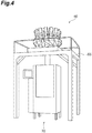
- the combination weighing apparatus 40 described above is disposed so as to be supported on a base 65 and is usually disposed at a position higher than the worker's eye level.
- the worker can get on and off the base 65.
- the bag-making and packing apparatus 70 is disposed below the combination weighing apparatus 40.
- the real space viewed by the worker generally matches the real space captured by the imaging unit 15, and an image of the combination weighing apparatus 40 captured from below the base 65 appears on the display unit 11 of the HMD 10.
- the worker can see the combination weighing apparatus 40 captured from below the base 65 through the display unit 11 of the HMD 10.
- the imaging unit 15 transmits data of the combination weighing apparatus 40 captured from below the base 65 to the management server 20.
- the identifying unit 22 identifies from which direction the combination weighing apparatus 40 is captured by the imaging unit 15, based on the captured data transmitted from the imaging unit 15. In the present embodiment, from which direction “up”, “down”, “left”, or “right” the combination weighing apparatus 40 is captured by the imaging unit 15 is identified. In this case, the identifying unit 22 identifies that the combination weighing apparatus 40 is captured by the imaging unit 15 from the lower direction.
- the display controller 23 causes the display unit 11 to display the operating status display screen 12A (see FIG. 7(A) ) of the combination weighing apparatus 40.
- the operating status display screen 12A for example, the name of a commodity processed by the combination weighing apparatus 40, the processing capability, the combination target value, the number of heads (hoppers) for realizing the combination target value, and the respective intensity and time of the supply troughs 44a are displayed.
- the amount of information displayed at a time on the display unit 11 is defined.
- the worker can operate the keys for selecting up, down, left, and down in the input unit 16 to scroll the information appearing on the display unit 11.
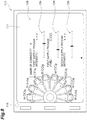
- the worker wearing the HMD 10 climbs on the base 65 and views the combination weighing apparatus 40 from the upper direction as illustrated in FIG. 6 will be described.
- the real space viewed by the worker generally matches the real space captured by the imaging unit 15, and the combination weighing apparatus 40 captured from the upper direction is displayed on the display unit 11 of the HMD 10.
- the worker can see the combination weighing apparatus 40 captured from the upper direction through the display unit 11 of the HMD 10.
- the upper direction is not necessarily a view from immediately above but refers to a view from a direction including the upper direction component, such as the upper right.
- the imaging unit 15 transmits data of the combination weighing apparatus 40 captured from the upper direction to the management server 20.
- the identifying unit 22 identifies from which direction the combination weighing apparatus 40 is captured by the imaging unit 15, based on the data transmitted from the imaging unit 15.
- the identifying unit 22 identifies that the combination weighing apparatus 40 is captured by the imaging unit 15 from the upper direction.
- the display controller 23 causes the display unit 11 to display the adjustment screen 12B (see FIG. 7(B) ) of the combination weighing apparatus 40.
- the display controller 23 may cause the display unit 11 to display the adjustment screen 12B only when the direction identified by the identifying unit 22 is a predetermined direction (in the present embodiment, the upper direction).
- the adjustment screen 12B is not necessarily displayed on the display unit 11 when the direction identified by the identifying unit 22 is not a predetermined direction as well as when some operation is performed through the input unit 16.
- the adjustment screen 12B for example, the name of a commodity processed by the combination weighing apparatus 40, the weight value for each weighing hopper 46 (for example, the weight value at present), and an adjuster for each operation parameter in the combination weighing apparatus 40 are displayed.
- the weight value for each weighing hopper 46 include the weight value at present and the most recent average weight value.
- the most recent average weight value may be the most recent average weight value per predetermined time or may be the most recent average weight value per predetermined number of times. That is, the value displayed in the vicinity of this weighing hopper 46 may be any value that is related to the weight value measured in the weighing hopper 46.
- FIG. 7(B) illustrates an example in which the weight value at present is displayed.
- the most recent average weight value may be displayed instead of the weight value at present, or the most recent average weight value may be displayed in addition to the weight value at present.
- the weight value for each weighing hopper 46 is displayed so as to be superimposed in the vicinity of the corresponding weighing hopper 46.
- Examples of the adjuster for each operation parameter include an intensity adjuster 13A for adjusting the intensity for each supply trough of the combination weighing apparatus 40 and a time adjuster 13B for adjusting the vibration time for each supply trough.
- the intensity adjuster 13A includes a numerical value display indicating the setting intensity and a slider for adjusting the setting intensity. The worker adjusts the setting intensity by moving the slider through operation of the left/right keys in the input unit 16.
- the time adjuster 13B includes a numerical value display indicating the setting time and a slider for adjusting the setting time. The worker adjusts the setting time by moving the slider through operation of the left/right keys in the input unit 16. The worker can adjust the intensity and/or the vibration time for each supply trough while looking at the weight value for each weighing hopper 46 displayed on the display unit 11, thereby setting the intensity and/or the vibration time as more appropriate.
- the adjusted operation parameter in one processing apparatus is transmitted to the management server 20.
- the communication unit 21 transmits the adjusted parameter to the one processing apparatus.
- the operation of the one processing apparatus receiving the adjusted parameter is controlled by the adjusted parameter.
- the adjusted setting intensity or setting time is transmitted to the management server 20 through the communication unit 17.
- the adjusted setting intensity or setting time is transmitted to the combination weighing apparatus 40 through the communication unit 21.
- the controller 60 of the combination weighing apparatus 40 receiving the adjusted setting intensity or setting time controls the supply trough 44a with the adjusted setting intensity or setting time.
- the parts whose operation parameters can be adjusted in the combination weighing apparatus 40 include, for example, the supply troughs 44a, the distributing table 43, and the gates 46a, 47a, and 49a of the hoppers 46, 47, and 49.
- the same part may include a plurality of parts, as is the case with the above-noted supply trough 44a.
- the display controller 23 displays only the adjustment screen 12B for adjusting the operation parameter about conveyance of the one supply trough 44a, among the respective adjustment screens in a plurality of supply trough 44a, on the display unit 11.
- FIG. 6 illustrates an example in which only one supply trough 44a is captured by the imaging unit 15.
- the display controller 23 displays only the respective adjustment screens 12B for adjusting two supply troughs 44a on the display unit 11.
- the matching of the part captured by the imaging unit 15 with the adjustment screen 12B to be displayed on the display unit 11 is implemented, for example, by providing an identifier 9 on the part.
- the identifier 9 is a two-dimensional code in which information for identifying each part is embedded.
- the display controller 23 can identify which part in one processing apparatus is captured by the imaging unit 15, that is, which part in one processing apparatus is displayed on the display unit 11, based on the identifier 9 captured by the imaging unit 15.
- the display controller 23 displays only the adjustment screen 12B corresponding to the identified part on the display unit 11.
- the matching with the adjustment screen 12B to be displayed on the display unit 11 can be implemented by a method other than using the identifier 9.
- the image captured by the imaging unit 15 may be analyzed, or when the HMD 10 is equipped with a sensor capable of acquiring the position, altitude (height), direction, etc., such information may be used.
- the operation effect of the work assistance system 1 in the foregoing embodiment is described.
- information suitable for a state is provided to the worker, based on the assumption that in a state in which the worker wishes to adjust the operation of one processing apparatus, the worker would view the processing apparatus from the upper direction (particular one direction).
- information to be provided to the worker can be provided at an appropriate timing based on the state of the worker.
- the work efficiency of the worker can be improved.
- the display unit 11 displays the real space in a factory and the adjustment screen 12B so as to overlap each other.
- the processing apparatus and the adjustment screen 12B for adjusting the operation parameter in the processing apparatus are displayed in an overlapped state.
- the worker can intuitively understand for which apparatus the parameter is to be adjusted on the adjustment screen 12B appearing on the display unit 11.
- the operation parameter of a processing apparatus can be changed by adjusting the operation parameter in the adjustment screen 12B appearing on the portable HMD 10. This configuration enables the worker to adjust the processing apparatus more efficiently.
- the display controller 23 allows the adjustment screen 12B to be displayed only when the direction identified by the identifying unit 22 is the upper direction (predetermined direction). This configuration prevents the adjustment screen 12B from appearing on the display unit 11 with easy operation and therefore prevents the setting of the processing apparatus from being changed carelessly.
- information suitable for a state is provided to the worker, based on the assumption that in a state in which the worker wishes to check the state of one processing apparatus, the worker would view the processing apparatus from a direction different from the upper direction.
- information to be provided to the worker can be switched at an appropriate timing based on the state of the worker. As a result, the work efficiency of the worker can be improved.
- the display controller 23 displays only the adjustment screen 12B for adjusting the operation parameter for the part captured by the imaging unit 15 on the display unit 11.
- the adjustment screen 12B for adjusting the operation parameter of the part assumed to be viewed by the worker is displayed.
- the display controller 23 allows the adjustment screen 12B of the combination weighing apparatus 40 to be displayed.
- information suitable for a state is provided to the worker based on the assumption that in a state in which the worker wishes to adjust the operation of one combination weighing apparatus 40, the worker would go onto the base 65 and view the combination weighing apparatus 40 from the upper direction, and in a state in which the worker wishes to check the state of one combination weighing apparatus 40, the worker would view so as to look up the one combination weighing apparatus 40 from below the base 65.
- information to be provided to the worker (the adjustment screen 12B or the operating status display screen 12A) can be switched at an appropriate timing based on the state of the worker. As a result, the work efficiency of the worker can be improved.
- a portable HMD 10 in the shape of eyeglasses is employed as an apparatus including the display unit 11 and the imaging unit 15.
- a tablet PC 110 including a display unit 111 and an imaging unit 115 as illustrated in FIG. 8 may be employed.
- the similar effect to the foregoing embodiment can be achieved since the image appearing on the display unit 111 through the imaging unit 115 can be matched with the image viewed by the worker.
- the worker has to hold the tablet PC 110 in hand, whereas the HMD 10 which is one of wearable terminals makes the worker's hands free.
- the workability is good.
- a plurality of supply troughs 44a included in the combination weighing apparatus 40 are displayed (captured by the imaging unit 15).
- the adjustment screen 12B appears that enables adjustment of the respective operation parameters of a plurality of supply troughs 44a displayed on the display unit 111.
- the adjusters for those other than the first supply trough and the second supply trough that do not appear on the display unit 111 in FIG. 8 can be displayed by operating the input unit 16.
- the adjusted operation parameter is transmitted to each processing apparatus through the management server 20.
- the adjusted operation parameter may be directly transmitted to each processing apparatus through the communication unit 17 included in the HMD 10.
- the operating status display screen 12A and the adjustment screen 12B related to the combination weighing apparatus 40 are displayed on the display unit 11.
- an operating status display screen and an adjustment screen related to a processing apparatus other than the combination weighing apparatus 40 specifically, the conveyance apparatus 35, the bag-making and packing apparatus 70, the seal inspection apparatus 75, the X-ray inspection apparatus 80, the metal detector 85, the weight checking apparatus 90, and the case packing apparatus 95, may be displayed on the display unit 11.
- the display controller 23 determines from which direction the processing apparatus captured by the imaging unit 15, 115 is captured and, if the direction is a predetermined direction, causes the display unit 11 to display an adjustment screen related to the apparatus, and if the direction is a direction other than the predetermined direction, causes the display unit 11 to display an operating status display screen related to the apparatus.
- the adjustment screen 12B when it is determined that data of the combination weighing apparatus 40 captured by the imaging unit 15 is captured from the upper direction (predetermined direction) by the imaging unit 15, the adjustment screen 12B is displayed on the display unit 11.
- the lateral direction (side) or the lower direction (below) other than the upper direction may be set as a predetermined direction.
Landscapes
- Engineering & Computer Science (AREA)
- Theoretical Computer Science (AREA)
- General Engineering & Computer Science (AREA)
- Physics & Mathematics (AREA)
- General Physics & Mathematics (AREA)
- Human Computer Interaction (AREA)
- Manufacturing & Machinery (AREA)
- Automation & Control Theory (AREA)
- Business, Economics & Management (AREA)
- Multimedia (AREA)
- Signal Processing (AREA)
- Computer Vision & Pattern Recognition (AREA)
- Quality & Reliability (AREA)
- Marketing (AREA)
- Economics (AREA)
- General Health & Medical Sciences (AREA)
- Human Resources & Organizations (AREA)
- Health & Medical Sciences (AREA)
- Primary Health Care (AREA)
- Strategic Management (AREA)
- Tourism & Hospitality (AREA)
- General Business, Economics & Management (AREA)
- General Factory Administration (AREA)
- User Interface Of Digital Computer (AREA)
- Management, Administration, Business Operations System, And Electronic Commerce (AREA)
Abstract
Description
- An aspect of the present disclosure relates to a work assistance system.
- A work assistance system is known which assists workers in operation, for example, in a factory using augmented reality (AR). For example, Patent Literature 1 discloses a work assistance system that displays additional information such as work explanatory information on a work target through an image display unit in the shape of eyeglasses disposed in front of the worker's eyes to cover the worker's field of vision.
- Patent Literature 1: Japanese Unexamined Patent Publication No.
2016-208331 - Such a system can provide workers with various information. However, there is a room for improvement in various points in order to improve the work efficiency of workers.
- An aspect of the present disclosure therefore is to provide a work assistance system that can improve the work efficiency of workers.
- A work assistance system according to an aspect of the present disclosure assists a worker working in a factory equipped with a plurality of processing apparatuses. The work assistance system includes a display unit having portability and configured to display information provided to the worker, an imaging unit having portability and configured to capture an image of the processing apparatus, a display controller configured to control a content of information displayed on the display unit, and an identifying unit configured to identify from which direction the processing apparatus is captured by the imaging unit, based on data captured by the imaging unit. When the direction identified by the identifying unit is a predetermined direction, the display controller causes the display unit to display an adjustment screen for adjusting an operation parameter of the processing apparatus captured by the imaging unit.
- In the work assistance system having this configuration, information suitable for a state is provided to the worker, based on the assumption that in a state in which the worker wishes to adjust the operation of one processing apparatus, the worker would view the processing apparatus from a particular one direction. In this configuration, information to be provided to the worker (the adjustment screen for the operation parameter) can be provided at an appropriate timing based on the state of the worker. As a result, the work efficiency of the worker can be improved.
- In the work assistance system according to an aspect of the present disclosure, the display unit may display a real space in the factory and the adjustment screen so as to overlap each other. In the work assistance system having this configuration, the processing apparatus and the adjustment screen for adjusting an operation parameter in the processing apparatus are displayed in an overlapped state. As a result, the worker can intuitively understand for which apparatus the parameter is to be adjusted on the adjustment screen appearing on the display unit.
- The work assistance system according to an aspect of the present disclosure may further include an input unit configured to input the operation parameter in the adjustment screen and a communication unit configured to transmit the operation parameter input through the input unit to the processing apparatus. In the work assistance system having this configuration, the operation parameter of the processing apparatus can be changed through the display unit having portability, the input unit, and the communication unit. This configuration enables the worker to adjust the processing apparatus more efficiently.
- In the work assistance system according to an aspect of the present disclosure, the display controller may allow the adjustment screen to be displayed only when the direction identified by the identifying unit is a predetermined direction. The work assistance system having this configuration prevents the adjustment screen from appearing on the display unit with easy operation and therefore prevents the setting of the processing apparatus from being changed carelessly.
- In the work assistance system according to an aspect of the present disclosure, when the direction identified by the identifying unit is a predetermined direction, the display controller may cause the display unit to display the adjustment screen corresponding to the processing apparatus captured by the imaging unit, and when the direction identified by the identifying unit is a direction other than the predetermined direction, the display controller may cause the display unit to display an operating status display screen displaying an operating status of the processing apparatus captured by the imaging unit. In the work assistance system having this configuration, information suitable for a state is provided to the worker, based on the assumption that in a state in which the worker wishes to adjust the operation of one processing apparatus, the worker would view the processing apparatus from a particular one direction, and in a state in which the worker wishes to check the state of one processing apparatus, the worker would view the processing apparatus from a different direction. In this configuration, information to be provided to the worker (the adjustment screen for the operation parameter or the operating status display screen) can be switched at an appropriate timing based on the state of the worker. As a result, the work efficiency of the worker can be improved.
- In the work assistance system according to an aspect of the present disclosure, when the direction identified by the identifying unit is a predetermined direction and only some of parts included in the processing apparatus are captured by the imaging unit, the display controller may display the adjustment screen only corresponding to the part captured by the imaging unit on the display unit. In the work assistance system having this configuration, a screen appears that enables adjustment of only the operation parameter of the part assumed to be viewed by the worker. As a result, only the minimum information required by the worker is provided, and adjustment of an unintended part can be prevented.
- In the work assistance system according to an aspect of the present disclosure, the processing apparatus may be a combination weighing apparatus configured to combination-weigh an article externally charged and supply the combination-weighed article to another processing apparatus disposed on a downstream side. When the direction identified by the identifying unit is an upper direction (above) of the combination weighing apparatus, the display controller may allow the adjustment screen of the combination weighing apparatus to be displayed. In the work assistance system having this configuration, information suitable for a state is provided to the worker, based on the assumption that in a state in which the worker wishes to adjust the operation of one combination weighing apparatus, the worker would get on a base and view the combination weighing apparatus from the upper direction. In the work assistance system having this configuration, information suitable for a state is provided to the worker, based on the assumption that in a state in which the worker wishes to check the state of one combination weighing apparatus, the worker would view so as to look up the one combination weighing apparatus from the lower direction. In this configuration, information to be provided to the worker (the adjustment screen for the operation parameter of the combination weighing apparatus or the operating status display screen of the combination weighing apparatus) can be switched at an appropriate timing based on the state of the worker. As a result, the work efficiency of the worker can be improved.
- According to an aspect of the present disclosure, the work efficiency of workers can be improved.
-
-
FIG. 1 is a diagram illustrating a configuration of a work assistance system according to an embodiment. -
FIG. 2 is a front view illustrating a production line deployed in a factory in which the work assistance system inFIG. 1 is used. -
FIG. 3 is a schematic configuration diagram of a combination weighing apparatus inFIG. 2 . -
FIG. 4 is a perspective view illustrating a bag-making and packing apparatus inFIG. 2 and the combination weighing apparatus disposed on a base. -
FIG. 5 is a diagram of the combination weighing apparatus inFIG. 4 as viewed from the lower direction through a mount head display. -
FIG. 6 is a diagram of the combination weighing apparatus inFIG. 4 as viewed from the upper direction of the combination weighing apparatus through the mount head display. -
FIG. 7(A) is a diagram illustrating a display example of state information of the combination weighing apparatus appearing on the mount head display, andFIG. 7(B) is a diagram illustrating a display example of an adjustment screen of the combination weighing apparatus appearing on the mount head display. -
FIG. 8 is a front view illustrating a display device according to a modification. - A preferred embodiment according to an aspect of the present disclosure will be described in detail below with reference to the accompanying drawings. In a description of the drawings, the same or corresponding elements are denoted by the same reference signs and an overlapping description will be omitted.
- A work assistance system 1 in the present embodiment is a system that assists workers who work in a factory equipped with a plurality of processing apparatuses. In the present embodiment, the work assistance system 1 used in a factory equipped with a
production line 30 including aconveyance apparatus 35, acombination weighing apparatus 40, a bag-making andpacking apparatus 70, aseal inspection apparatus 75, anX-ray inspection apparatus 80, ametal detector 85, aweight checking apparatus 90, and acase packing apparatus 95 as processing apparatuses as illustrated inFIG. 2 is described by way of example. - The
conveyance apparatus 35 is an apparatus that conveys an article A (seeFIG. 3 ) from a supply unit to thecombination weighing apparatus 40 and supplies the article A to aninput chute 42 of thecombination weighing apparatus 40. Thecombination weighing apparatus 40 is an apparatus that weighs out a predetermined amount of the article A. The bag-making andpacking apparatus 70 is an apparatus that packs the article A weighed out by thecombination weighing apparatus 40 while making a bag for packing the article A. Theseal inspection apparatus 75 is an apparatus that detects abnormality of a bag made and packed by the bag-making andpacking apparatus 70. TheX-ray inspection apparatus 80 is an apparatus that inspects the state of the article A contained in a bag or inclusion of a foreign matter. Themetal detector 85 is an apparatus that inspects the article A contained in a bag for inclusion of metal. Theweight checking apparatus 90 is an apparatus that checks the weight of a commodity containing the article A. Thecase packing apparatus 95 is an apparatus that packs a commodity into a cardboard box. - As illustrated in
FIG. 1 , the work assistance system 1 includes a portable head mount display (hereinafter referred to as "HMD") 10 in the shape of eyeglasses and amanagement server 20. The HMD 10 has adisplay unit 11, animaging unit 15, aninput unit 16, and acommunication unit 17. - The
display unit 11 displays information provided to the worker. Thedisplay unit 11 displays (superimposes) the real space in the factory and information provided to the worker so as to overlap each other. Superimposition on thedisplay unit 11 is implemented, for example, by configuring thedisplay unit 11 with a half mirror or by projecting an image captured by theimaging unit 15 onto thedisplay unit 11. - The
imaging unit 15 captures an image of the real space in a factory. Theimaging unit 15 is provided such that the real space viewed by the worker wearing theHMD 10 generally matches the real space captured by theimaging unit 15. That is, theimaging unit 15 is a vision synchronous camera that captures a front view image in the eye direction of the worker. Theimaging unit 15 causes thedisplay unit 11 to display the captured data. Theimaging unit 15 also transmits the captured data to themanagement server 20. - The
input unit 16 includes keys to select up, down, left, and right and a key to confirm an entry. The worker can operate theinput unit 16 to select a menu appearing on thedisplay unit 11 or confirm a menu. - The
communication unit 17 is an interface for exchanging data with themanagement server 20. Communication with themanagement server 20 may be wireless or wired. - The
management server 20 is configured as a computer system including a central processing unit (CPU), a main memory such as a random access memory (RAM) and a read only memory (ROM), an auxiliary storage such as a hard disk and a flash memory, an input unit such as a keyboard and a mouse, and an output unit such as a display screen. The functions of an identifyingunit 22 and adisplay controller 23 described in detail in the subsequent sections are executed under the control of the CPU by loading predetermined computer software into hardware such as the CPU and the main memory. - The
management server 20 is connected to communicate with each of theconveyance apparatus 35, thecombination weighing apparatus 40, the bag-making and packingapparatus 70, theseal inspection apparatus 75, theX-ray inspection apparatus 80, themetal detector 85, theweight checking apparatus 90, and thecase packing apparatus 95 through acommunication unit 21. Themanagement server 20 and each processing apparatus may be connected wirelessly or may be connected by wire. Themanagement server 20 can control the operation of the processing apparatuses included in theproduction line 30. Themanagement server 20 is also connected to communicate with theHMD 10 through thecommunication unit 21. - The identifying
unit 22 identifies from which direction one processing apparatus is captured by theimaging unit 15, based on data on the one processing apparatus captured by theimaging unit 15. In the present embodiment, from which direction "up", "down", "left", or "right" one processing apparatus is captured by theimaging unit 15 is identified. The capturing direction may be identified by matching the captured image with an image stored in advance or may be identified using information such as position, altitude (height), and direction, if a sensor capable of acquiring such information is installed in theHMD 10. - The
display controller 23 controls the content of information appearing on thedisplay unit 11 of theHMD 10. When the identifyingunit 22 identifies that the image of one processing apparatus captured by theimaging unit 15 is captured from a predetermined direction, thedisplay controller 23 causes thedisplay unit 11 to display an adjustment screen for adjusting an operation parameter of the one processing apparatus. When the identifyingunit 22 identifies that the image of one processing apparatus captured by theimaging unit 15 is captured from the upper direction (above), thedisplay controller 23 in the present embodiment causes thedisplay unit 11 to display anadjustment screen 12B (seeFIG. 7(B) ) for adjusting an operation parameter of the one processing apparatus. When the identifyingunit 22 identifies that the image of one processing apparatus captured by theimaging unit 15 is captured from a direction other than the upper direction, thedisplay controller 23 in the present embodiment causes thedisplay unit 11 to display an operatingstatus display screen 12A (seeFIG. 7(A) ) that displays information about the operating status of the operation parameter of the one processing apparatus. - For example, when the identifying
unit 22 identifies that the target captured by theimaging unit 15 is thecombination weighing apparatus 40 and its image is captured from the upper direction of thecombination weighing apparatus 40, thedisplay controller 23 causes thedisplay unit 11 to display theadjustment screen 12B (seeFIG. 7(B) ) of thecombination weighing apparatus 40. On the other hand, when the identifyingunit 22 identifies that the image is captured from a direction (for example, lower direction) other than the upper direction of thecombination weighing apparatus 40, thedisplay controller 23 causes thedisplay unit 11 to display the operatingstatus display screen 12A (seeFIG. 7(A) ) of thecombination weighing apparatus 40. - The
combination weighing apparatus 40 which is one processing apparatus in theproduction line 30 will now be described in detail, and the timing at which the operatingstatus display screen 12A and theadjustment screen 12B for thecombination weighing apparatus 40 are distributed from the work assistance system 1 to theHMD 10 will be described. - As illustrated in
FIG. 3 , thecombination weighing apparatus 40 includes aninput chute 42, a distributing table 43, a plurality ofradial feeders 44, a plurality ofpool hoppers 45, a plurality of weighinghoppers 46, a plurality ofbooster hoppers 47, a collectingchute 48, atiming hopper 49, a weighingunit 51, and acontroller 60. Thecombination weighing apparatus 40 weighs the article A supplied by theconveyance apparatus 35 at a target weight value and supplies the weighed article A to the bag-making and packingapparatus 70. Here, the article A is an article that varies in individual mass, such as agricultural products, fishery products, and processed food products. The bag-making and packingapparatus 70 bags the article weighed and supplied by thecombination weighing apparatus 40 while shaping a film into a bag with a predetermined capacity. - The
input chute 42 is arranged below a conveyance end of theconveyance apparatus 35. Theinput chute 42 is a tubular member having an inner hollow portion with openings above and below. The article A dropping from the conveyance end of theconveyance apparatus 35 is charged into the inner hollow portion of theinput chute 42. The article A dropped into the inner hollow portion is discharged to the distributing table 43 through the opening below. - The distributing table 43 is disposed below the
input chute 42. The distributing table 43 has aconical conveyance surface 43a expanding downward. The distributing table 43 rotates theconveyance surface 43a to convey the article A discharged from theinput chute 42 to the apex portion of theconveyance surface 43a uniformly toward the outer edge of theconveyance surface 43a. - A
driver 55 rotates the distributing table 43 about the center portion of the distributing table 43. An example of thedriver 55 is a motor. Thedriver 55 intermittently rotates the distributing table 43. That is, the distributing table 43 repeats rotating and stopping. - A plurality of
radial feeders 44 are disposed radially along the outer edge of theconveyance surface 43a that is a surface of the distributing table 43. Eachradial feeder 44 has asupply trough 44a extending from below the outer edge of theconveyance surface 43a toward the outer edge. Eachradial feeder 44 vibrates thesupply trough 44a to convey the article A discharged from the outer edge of theconveyance surface 43a toward the front end portion of thesupply trough 44a. - Each
pool hopper 45 is disposed below the front end portion of thesupply trough 44a of eachradial feeder 44. At the bottom portion of eachpool hopper 45, agate 45a that can be opened and closed is provided. Eachpool hopper 45 temporarily stores the article A discharged from the front end portion of thecorresponding supply trough 44a with thegate 45a closed and discharges the temporarily stored article A downward when thegate 45a is opened. - Each weighing
hopper 46 is disposed below thegate 45a of eachpool hopper 45. At the bottom portion of each weighinghopper 46, agate 46a and agate 46b that can be opened and closed are provided. Each weighinghopper 46 temporarily stores the article A discharged from the correspondingpool hopper 45 with thegate 46a and thegate 46b closed and discharges the temporarily stored article A downward when thegate 46a or thegate 46b is opened. - Each
booster hopper 47 is disposed below thegate 46a of the corresponding weighinghopper 46. At the bottom portion of eachbooster hopper 47, agate 47a that can be opened and closed is provided. Eachbooster hopper 47 temporarily stores the article A discharged from thegate 46a side of the corresponding weighinghopper 46 with thegate 47a closed and discharges the temporarily stored article A downward when thegate 47a is opened. - The collecting
chute 48 is formed in a tubular shape having aninner surface 48a shaped in a truncated cone tapered downward. The collectingchute 48 is disposed such that theinner surface 48a is positioned below all of the weighinghoppers 46 and all of thebooster hoppers 47. The collectingchute 48 receives the article A discharged from thegate 46b side of each weighinghopper 46 and the article A discharged from eachbooster hopper 47 on theinner surface 48a and discharges the article A downward. - The
timing hopper 49 is disposed below the collectingchute 48. At the bottom portion of thetiming hopper 49, agate 49a that can be opened and closed is provided. Thetiming hopper 49 temporarily stores the article A discharged from the collectingchute 48 with thegate 49a closed and discharges the temporarily stored article A to the bag-making and packingapparatus 70 when thegate 49a is opened. - The
input chute 42, the distributing table 43, a plurality ofradial feeders 44, a plurality ofpool hoppers 45, and a plurality of weighinghoppers 46 are supported directly or indirectly on acase 53. A plurality ofbooster hoppers 47, the collectingchute 48, and thetiming hopper 49 are supported directly or indirectly on aframe 52. - The weighing
unit 51 is disposed in thecase 53 supported by theframe 52. The weighingunit 51 has a plurality ofload cells 51a. Eachload cell 51a supports the corresponding weighinghopper 46. The weighingunit 51 measures a weight value corresponding to the mass of the article A when the article A is temporarily stored in each weighinghopper 46. - The
controller 60 is disposed in thecase 53. Thecontroller 60 is a device controlling various operations in thecombination weighing apparatus 40 and is a signal processing apparatus including a CPU, a ROM, and a RAM. Thecontroller 60 controls the operation of each unit of thecombination weighing apparatus 40, such as conveyance operation of the distributing table 43 and eachradial feeder 44, the opening/closing operation of thegate 45a of eachpool hopper 45, the opening/closing operation of thegate 46a and thegate 46b of each weighinghopper 46, the opening/closing operation of thegate 47a of eachbooster hopper 47, and thegate 49a of eachtiming hopper 49. - The
controller 60 selects a combination of weight values from among a plurality of weight values measured by the weighingunit 51 and associated with a plurality of weighinghoppers 46 and/orbooster hoppers 47 such that the total value attains a target weight value. Specifically, thecontroller 60 selects a combination of weight values from among a plurality of weight values output by the weighingunit 51 such that the total value falls within a predetermined range with a target weight value as a lower limit value. Thecontroller 60 then allows the weighinghopper 46 and/or thebooster hopper 47 corresponding to the combination to discharge the article A. - As illustrated in
FIG. 4 , thecombination weighing apparatus 40 described above is disposed so as to be supported on abase 65 and is usually disposed at a position higher than the worker's eye level. The worker can get on and off thebase 65. For example, when performing maintenance of thecombination weighing apparatus 40, the worker gets on the base 65 to conduct work. The bag-making and packingapparatus 70 is disposed below thecombination weighing apparatus 40. - As illustrated in
FIG. 5 , a case where a worker wearing theHMD 10 views thecombination weighing apparatus 40 disposed on thebase 65, from below thebase 65. In this case, the real space viewed by the worker generally matches the real space captured by theimaging unit 15, and an image of thecombination weighing apparatus 40 captured from below thebase 65 appears on thedisplay unit 11 of theHMD 10. The worker can see thecombination weighing apparatus 40 captured from below thebase 65 through thedisplay unit 11 of theHMD 10. - The
imaging unit 15 transmits data of thecombination weighing apparatus 40 captured from below the base 65 to themanagement server 20. The identifyingunit 22 identifies from which direction thecombination weighing apparatus 40 is captured by theimaging unit 15, based on the captured data transmitted from theimaging unit 15. In the present embodiment, from which direction "up", "down", "left", or "right" thecombination weighing apparatus 40 is captured by theimaging unit 15 is identified. In this case, the identifyingunit 22 identifies that thecombination weighing apparatus 40 is captured by theimaging unit 15 from the lower direction. - Next, for example, when the identifying
unit 22 identifies that data captured by theimaging unit 15 is captured from, for example, the lower direction other than the upper direction of thecombination weighing apparatus 40, thedisplay controller 23 causes thedisplay unit 11 to display the operatingstatus display screen 12A (seeFIG. 7(A) ) of thecombination weighing apparatus 40. - In the operating
status display screen 12A, for example, the name of a commodity processed by thecombination weighing apparatus 40, the processing capability, the combination target value, the number of heads (hoppers) for realizing the combination target value, and the respective intensity and time of thesupply troughs 44a are displayed. The amount of information displayed at a time on thedisplay unit 11 is defined. The worker can operate the keys for selecting up, down, left, and down in theinput unit 16 to scroll the information appearing on thedisplay unit 11. - Next, a case where the worker wearing the
HMD 10 climbs on thebase 65 and views thecombination weighing apparatus 40 from the upper direction as illustrated inFIG. 6 will be described. In this case, as described above, the real space viewed by the worker generally matches the real space captured by theimaging unit 15, and thecombination weighing apparatus 40 captured from the upper direction is displayed on thedisplay unit 11 of theHMD 10. The worker can see thecombination weighing apparatus 40 captured from the upper direction through thedisplay unit 11 of theHMD 10. As used herein the upper direction is not necessarily a view from immediately above but refers to a view from a direction including the upper direction component, such as the upper right. - The
imaging unit 15 transmits data of thecombination weighing apparatus 40 captured from the upper direction to themanagement server 20. The identifyingunit 22 identifies from which direction thecombination weighing apparatus 40 is captured by theimaging unit 15, based on the data transmitted from theimaging unit 15. Here, the identifyingunit 22 identifies that thecombination weighing apparatus 40 is captured by theimaging unit 15 from the upper direction. - Next, when the identifying
unit 22 identifies that data captured by theimaging unit 15 is captured from the upper direction of thecombination weighing apparatus 40, thedisplay controller 23 causes thedisplay unit 11 to display theadjustment screen 12B (seeFIG. 7(B) ) of thecombination weighing apparatus 40. Thedisplay controller 23 may cause thedisplay unit 11 to display theadjustment screen 12B only when the direction identified by the identifyingunit 22 is a predetermined direction (in the present embodiment, the upper direction). Theadjustment screen 12B is not necessarily displayed on thedisplay unit 11 when the direction identified by the identifyingunit 22 is not a predetermined direction as well as when some operation is performed through theinput unit 16. - In the
adjustment screen 12B, for example, the name of a commodity processed by thecombination weighing apparatus 40, the weight value for each weighing hopper 46 (for example, the weight value at present), and an adjuster for each operation parameter in thecombination weighing apparatus 40 are displayed. Examples of the weight value for each weighinghopper 46 include the weight value at present and the most recent average weight value. The most recent average weight value may be the most recent average weight value per predetermined time or may be the most recent average weight value per predetermined number of times. That is, the value displayed in the vicinity of this weighinghopper 46 may be any value that is related to the weight value measured in the weighinghopper 46.FIG. 7(B) illustrates an example in which the weight value at present is displayed. However, the most recent average weight value may be displayed instead of the weight value at present, or the most recent average weight value may be displayed in addition to the weight value at present. The weight value for each weighinghopper 46 is displayed so as to be superimposed in the vicinity of the corresponding weighinghopper 46. - Examples of the adjuster for each operation parameter include an
intensity adjuster 13A for adjusting the intensity for each supply trough of thecombination weighing apparatus 40 and atime adjuster 13B for adjusting the vibration time for each supply trough. Theintensity adjuster 13A includes a numerical value display indicating the setting intensity and a slider for adjusting the setting intensity. The worker adjusts the setting intensity by moving the slider through operation of the left/right keys in theinput unit 16. Similarly, thetime adjuster 13B includes a numerical value display indicating the setting time and a slider for adjusting the setting time. The worker adjusts the setting time by moving the slider through operation of the left/right keys in theinput unit 16. The worker can adjust the intensity and/or the vibration time for each supply trough while looking at the weight value for each weighinghopper 46 displayed on thedisplay unit 11, thereby setting the intensity and/or the vibration time as more appropriate. - When the operation parameter in one processing apparatus is adjusted in the
adjustment screen 12B, the adjusted operation parameter is transmitted to themanagement server 20. Thecommunication unit 21 transmits the adjusted parameter to the one processing apparatus. The operation of the one processing apparatus receiving the adjusted parameter is controlled by the adjusted parameter. In the present embodiment, when the setting intensity or the setting time is adjusted in theadjustment screen 12B, the adjusted setting intensity or setting time is transmitted to themanagement server 20 through thecommunication unit 17. The adjusted setting intensity or setting time is transmitted to thecombination weighing apparatus 40 through thecommunication unit 21. Thecontroller 60 of thecombination weighing apparatus 40 receiving the adjusted setting intensity or setting time controls thesupply trough 44a with the adjusted setting intensity or setting time. - The parts whose operation parameters can be adjusted in the
combination weighing apparatus 40 include, for example, thesupply troughs 44a, the distributing table 43, and thegates hoppers supply trough 44a. When theadjustment screen 12B as described above is displayed, thedisplay controller 23 causes thedisplay unit 11 to display theadjustment screen 12B of only the part captured by theimaging unit 15. - For example, as illustrated in
FIG. 6 , when only onesupply trough 44a of a plurality ofsupply troughs 44a is captured by the imaging unit 15 (only onesupply trough 44a of a plurality ofsupply troughs 44a is displayed on the display unit 11), thedisplay controller 23 displays only theadjustment screen 12B for adjusting the operation parameter about conveyance of the onesupply trough 44a, among the respective adjustment screens in a plurality ofsupply trough 44a, on thedisplay unit 11.FIG. 6 illustrates an example in which only onesupply trough 44a is captured by theimaging unit 15. However, when twosupply troughs 44a are captured by theimaging unit 15, thedisplay controller 23 displays only the respective adjustment screens 12B for adjusting twosupply troughs 44a on thedisplay unit 11. - The matching of the part captured by the
imaging unit 15 with theadjustment screen 12B to be displayed on thedisplay unit 11 is implemented, for example, by providing anidentifier 9 on the part. For example, theidentifier 9 is a two-dimensional code in which information for identifying each part is embedded. Thedisplay controller 23 can identify which part in one processing apparatus is captured by theimaging unit 15, that is, which part in one processing apparatus is displayed on thedisplay unit 11, based on theidentifier 9 captured by theimaging unit 15. Thedisplay controller 23 displays only theadjustment screen 12B corresponding to the identified part on thedisplay unit 11. The matching with theadjustment screen 12B to be displayed on thedisplay unit 11 can be implemented by a method other than using theidentifier 9. For example, the image captured by theimaging unit 15 may be analyzed, or when theHMD 10 is equipped with a sensor capable of acquiring the position, altitude (height), direction, etc., such information may be used. - The operation effect of the work assistance system 1 in the foregoing embodiment is described. In the work assistance system 1 in the foregoing embodiment, information suitable for a state is provided to the worker, based on the assumption that in a state in which the worker wishes to adjust the operation of one processing apparatus, the worker would view the processing apparatus from the upper direction (particular one direction). In this configuration, information to be provided to the worker (the
adjustment screen 12B for the operation parameter of the processing apparatus) can be provided at an appropriate timing based on the state of the worker. As a result, the work efficiency of the worker can be improved. - In the foregoing embodiment, the
display unit 11 displays the real space in a factory and theadjustment screen 12B so as to overlap each other. In this configuration, the processing apparatus and theadjustment screen 12B for adjusting the operation parameter in the processing apparatus are displayed in an overlapped state. As a result, the worker can intuitively understand for which apparatus the parameter is to be adjusted on theadjustment screen 12B appearing on thedisplay unit 11. - In the foregoing embodiment, the operation parameter of a processing apparatus can be changed by adjusting the operation parameter in the
adjustment screen 12B appearing on theportable HMD 10. This configuration enables the worker to adjust the processing apparatus more efficiently. - In the foregoing embodiment, the
display controller 23 allows theadjustment screen 12B to be displayed only when the direction identified by the identifyingunit 22 is the upper direction (predetermined direction). This configuration prevents theadjustment screen 12B from appearing on thedisplay unit 11 with easy operation and therefore prevents the setting of the processing apparatus from being changed carelessly. - In the foregoing embodiment, information suitable for a state is provided to the worker, based on the assumption that in a state in which the worker wishes to check the state of one processing apparatus, the worker would view the processing apparatus from a direction different from the upper direction. In this configuration, information to be provided to the worker (the
adjustment screen 12B or the operatingstatus display screen 12A) can be switched at an appropriate timing based on the state of the worker. As a result, the work efficiency of the worker can be improved. - In the foregoing embodiment, when only some of the parts included in the processing apparatus are captured by the
imaging unit 15, thedisplay controller 23 displays only theadjustment screen 12B for adjusting the operation parameter for the part captured by theimaging unit 15 on thedisplay unit 11. In this configuration, only theadjustment screen 12B for adjusting the operation parameter of the part assumed to be viewed by the worker is displayed. As a result, only the minimum information required by the worker is provided, and adjustment of an unintended part can be prevented. - In the foregoing embodiment, when the direction identified by the identifying
unit 22 is the upper direction of thecombination weighing apparatus 40, thedisplay controller 23 allows theadjustment screen 12B of thecombination weighing apparatus 40 to be displayed. In this configuration, information suitable for a state is provided to the worker based on the assumption that in a state in which the worker wishes to adjust the operation of onecombination weighing apparatus 40, the worker would go onto thebase 65 and view thecombination weighing apparatus 40 from the upper direction, and in a state in which the worker wishes to check the state of onecombination weighing apparatus 40, the worker would view so as to look up the onecombination weighing apparatus 40 from below thebase 65. In this configuration, information to be provided to the worker (theadjustment screen 12B or the operatingstatus display screen 12A) can be switched at an appropriate timing based on the state of the worker. As a result, the work efficiency of the worker can be improved. - Although an embodiment has been described above, an aspect of the present disclosure is not limited to the foregoing embodiment and is susceptible to various modifications without departing from the spirit of the disclosure.
- In the foregoing embodiment, a
portable HMD 10 in the shape of eyeglasses is employed as an apparatus including thedisplay unit 11 and theimaging unit 15. However, for example, atablet PC 110 including adisplay unit 111 and animaging unit 115 as illustrated inFIG. 8 may be employed. Also in this case, the similar effect to the foregoing embodiment can be achieved since the image appearing on thedisplay unit 111 through theimaging unit 115 can be matched with the image viewed by the worker. However, the worker has to hold thetablet PC 110 in hand, whereas theHMD 10 which is one of wearable terminals makes the worker's hands free. When theHMD 10 is employed, the workability is good. - On the
display unit 111 illustrated inFIG. 8 , a plurality ofsupply troughs 44a included in thecombination weighing apparatus 40 are displayed (captured by the imaging unit 15). In this case, theadjustment screen 12B appears that enables adjustment of the respective operation parameters of a plurality ofsupply troughs 44a displayed on thedisplay unit 111. The adjusters for those other than the first supply trough and the second supply trough that do not appear on thedisplay unit 111 inFIG. 8 can be displayed by operating theinput unit 16. - In the foregoing embodiment, the adjusted operation parameter is transmitted to each processing apparatus through the
management server 20. However, the adjusted operation parameter may be directly transmitted to each processing apparatus through thecommunication unit 17 included in theHMD 10. - In the foregoing embodiment or modification, the operating
status display screen 12A and theadjustment screen 12B related to thecombination weighing apparatus 40 are displayed on thedisplay unit 11. However, an operating status display screen and an adjustment screen related to a processing apparatus other than thecombination weighing apparatus 40, specifically, theconveyance apparatus 35, the bag-making and packingapparatus 70, theseal inspection apparatus 75, theX-ray inspection apparatus 80, themetal detector 85, theweight checking apparatus 90, and thecase packing apparatus 95, may be displayed on thedisplay unit 11. Also in this case, similarly, thedisplay controller 23 determines from which direction the processing apparatus captured by theimaging unit display unit 11 to display an adjustment screen related to the apparatus, and if the direction is a direction other than the predetermined direction, causes thedisplay unit 11 to display an operating status display screen related to the apparatus. - In the foregoing embodiment or modification, when it is determined that data of the
combination weighing apparatus 40 captured by theimaging unit 15 is captured from the upper direction (predetermined direction) by theimaging unit 15, theadjustment screen 12B is displayed on thedisplay unit 11. However, for example, the lateral direction (side) or the lower direction (below) other than the upper direction may be set as a predetermined direction. However, based on a particular situation in which thecombination weighing apparatus 40 is often installed on thebase 65 and the operation for adjusting thecombination weighing apparatus 40 is usually done on the base, it is effective to set the upper direction as a predetermined direction in that theadjustment screen 12B for the operation parameter can be provided at an appropriate timing based on the state of the worker. - 1 ... work assistance system, 9 ... identifier, 10 ... HMD, 11 ... display unit, 12A ... operating status display screen, 12B ... adjustment screen, 13A ... intensity adjuster, 13B ... time adjuster, 15 ... imaging unit, 16 ... input unit, 17 ... communication unit, 20 ... management server, 21 ... communication unit, 22 ... identifying unit, 23 ... display controller, 30 ... production line, 40 ... combination weighing apparatus (processing apparatus), 44a ... supply trough, 65 ... base, 111 ... display unit, 115 ... imaging unit, 110 ... tablet PC.
Claims (7)
- A work assistance system that assists a worker working in a factory equipped with a plurality of processing apparatuses, the work assistance system comprising:a display unit having portability and configured to display information provided to the worker,an imaging unit having portability and configured to capture an image of the processing apparatus;a display controller configured to control a content of information displayed on the display unit; andan identifying unit configured to identify from which direction the processing apparatus is captured by the imaging unit, based on data captured by the imaging unit, whereinwhen the direction identified by the identifying unit is a predetermined direction, the display controller causes the display unit to display an adjustment screen for adjusting an operation parameter of the processing apparatus captured by the imaging unit.
- The work assistance system according to claim 1, wherein the display unit displays a real space in the factory and the adjustment screen so as to overlap each other.
- The work assistance system according to claim 1 or 2 further comprising:an input unit configured to input the operation parameter in the adjustment screen; anda communication unit configured to transmit the operation parameter input through the input unit to the processing apparatus.
- The work assistance system according to any one of claims 1 to 3, wherein the display controller allows the adjustment screen to be displayed only when the direction identified by the identifying unit is a predetermined direction.
- The work assistance system according to any one of claims 1 to 4, wherein
when the direction identified by the identifying unit is a predetermined direction, the display controller causes the display unit to display the adjustment screen corresponding to the processing apparatus captured by the imaging unit, and
when the direction identified by the identifying unit is a direction other than the predetermined direction, the display controller causes the display unit to display an operating status display screen displaying an operating status of the processing apparatus captured by the imaging unit. - The work assistance system according to claim 5, when the direction identified by the identifying unit is a predetermined direction and only some of parts included in the processing apparatus are captured by the imaging unit, the display controller displays the adjustment screen only corresponding to the part captured by the imaging unit on the display unit.
- The work assistance system according to any one of claims 1 to 6, wherein
the processing apparatus is a combination weighing apparatus configured to combination-weigh an article externally charged and supply the combination-weighed article to another processing apparatus disposed on a downstream side, and
when the direction identified by the identifying unit is an upper direction of the combination weighing apparatus, the display controller allows the adjustment screen of the combination weighing apparatus to be displayed.
Applications Claiming Priority (2)
| Application Number | Priority Date | Filing Date | Title |
|---|---|---|---|
| JP2017162721A JP2019040469A (en) | 2017-08-25 | 2017-08-25 | Work support system |
| PCT/JP2018/028927 WO2019039219A1 (en) | 2017-08-25 | 2018-08-01 | Work support system |
Publications (2)
| Publication Number | Publication Date |
|---|---|
| EP3674825A1 true EP3674825A1 (en) | 2020-07-01 |
| EP3674825A4 EP3674825A4 (en) | 2021-05-19 |
Family
ID=65438643
Family Applications (1)
| Application Number | Title | Priority Date | Filing Date |
|---|---|---|---|
| EP18847421.7A Withdrawn EP3674825A4 (en) | 2017-08-25 | 2018-08-01 | Work assistance system |
Country Status (5)
| Country | Link |
|---|---|
| US (1) | US20200249656A1 (en) |
| EP (1) | EP3674825A4 (en) |
| JP (1) | JP2019040469A (en) |
| CN (1) | CN111033408A (en) |
| WO (1) | WO2019039219A1 (en) |
Families Citing this family (2)
| Publication number | Priority date | Publication date | Assignee | Title |
|---|---|---|---|---|
| US20230251206A1 (en) * | 2022-02-09 | 2023-08-10 | Greyscale AI | System and method to determine a score indicating seal integrity in a package |
| JP2024094510A (en) * | 2022-12-28 | 2024-07-10 | 株式会社Screenホールディングス | Work support method and work support system |
Family Cites Families (13)
| Publication number | Priority date | Publication date | Assignee | Title |
|---|---|---|---|---|
| JP2006072442A (en) * | 2004-08-31 | 2006-03-16 | Digital Electronics Corp | Control system |
| DE102005061211B4 (en) * | 2004-12-22 | 2023-04-06 | Abb Schweiz Ag | Method for creating a human-machine user interface |
| JP2008003781A (en) * | 2006-06-21 | 2008-01-10 | Konica Minolta Holdings Inc | Operation monitoring system |
| JP2012256134A (en) * | 2011-06-07 | 2012-12-27 | Ishida Co Ltd | Inter-device information transmission system |
| US8941560B2 (en) * | 2011-09-21 | 2015-01-27 | Google Inc. | Wearable computer with superimposed controls and instructions for external device |
| JP5774450B2 (en) * | 2011-11-14 | 2015-09-09 | 株式会社日立産機システム | Industrial equipment control system |
| JP5785123B2 (en) * | 2012-03-16 | 2015-09-24 | 株式会社イシダ | Combination weighing device |
| KR20150028799A (en) * | 2012-07-03 | 2015-03-16 | 도쿄엘렉트론가부시키가이샤 | Fabrication equipment monitoring device and monitoring method |
| JP2014071756A (en) * | 2012-09-28 | 2014-04-21 | Brother Ind Ltd | Work assistance system and program |
| US11150482B2 (en) * | 2015-02-25 | 2021-10-19 | Facebook Technologies, Llc | Augmented reality content creation |
| JP2016208331A (en) | 2015-04-24 | 2016-12-08 | 三菱電機エンジニアリング株式会社 | Operation support system |
| KR20170055295A (en) * | 2015-11-11 | 2017-05-19 | 엘지전자 주식회사 | Mobile terminal and method for controlling the same |
| JP2017120584A (en) * | 2015-12-28 | 2017-07-06 | ソニー株式会社 | Information processor, information processing method, and program |
-
2017
- 2017-08-25 JP JP2017162721A patent/JP2019040469A/en active Pending
-
2018
- 2018-08-01 CN CN201880054669.5A patent/CN111033408A/en active Pending
- 2018-08-01 US US16/640,285 patent/US20200249656A1/en not_active Abandoned
- 2018-08-01 EP EP18847421.7A patent/EP3674825A4/en not_active Withdrawn
- 2018-08-01 WO PCT/JP2018/028927 patent/WO2019039219A1/en not_active Ceased
Also Published As
| Publication number | Publication date |
|---|---|
| WO2019039219A1 (en) | 2019-02-28 |
| CN111033408A (en) | 2020-04-17 |
| EP3674825A4 (en) | 2021-05-19 |
| JP2019040469A (en) | 2019-03-14 |
| US20200249656A1 (en) | 2020-08-06 |
Similar Documents
| Publication | Publication Date | Title |
|---|---|---|
| CN104487811B (en) | Combined metering device | |
| EP2796375A1 (en) | Quantitative packing scale for split loading of particles and quantitative weighing method therefor | |
| US4840240A (en) | Weighing and packing device | |
| JP5926618B2 (en) | Combination weighing device | |
| US20200249656A1 (en) | Work assistance system | |
| EP3224145B1 (en) | Food processing method and system | |
| EP3101398A1 (en) | Combination weighing apparatus | |
| WO2020111961A1 (en) | Intelligent refrigerator | |
| EP3617668B1 (en) | Combination weigher | |
| EP3677973A1 (en) | Work support system | |
| EP3985361B1 (en) | Combination weighing device | |
| EP3792604B1 (en) | Combination weighing device | |
| EP4024400A1 (en) | Identification and verification of medication | |
| JP2010078491A (en) | Combinational balance, and weighing and packaging system | |
| JP2010043974A (en) | Information processor for weighing device | |
| US20170144787A1 (en) | Automatic medicine packing machine | |
| JP7297296B2 (en) | Message information display confirmation device and pillow packaging machine | |
| JP5289159B2 (en) | Combination scale | |
| KR101842360B1 (en) | Smart Delivery Suit | |
| EP4628855A1 (en) | Combination weighing apparatus | |
| JP2010008246A (en) | Information processing device for weighing apparatus | |
| JP6064233B2 (en) | Health management system, terminal device, display method and control program | |
| US20150257713A1 (en) | Health management system, terminal device, display method, and control program | |
| JP2020201978A (en) | Powder preparation work support system | |
| JP5070017B2 (en) | Weighing and packaging system |
Legal Events
| Date | Code | Title | Description |
|---|---|---|---|
| STAA | Information on the status of an ep patent application or granted ep patent |
Free format text: STATUS: THE INTERNATIONAL PUBLICATION HAS BEEN MADE |
|
| PUAI | Public reference made under article 153(3) epc to a published international application that has entered the european phase |
Free format text: ORIGINAL CODE: 0009012 |
|
| STAA | Information on the status of an ep patent application or granted ep patent |
Free format text: STATUS: REQUEST FOR EXAMINATION WAS MADE |
|
| 17P | Request for examination filed |
Effective date: 20200217 |
|
| AK | Designated contracting states |
Kind code of ref document: A1 Designated state(s): AL AT BE BG CH CY CZ DE DK EE ES FI FR GB GR HR HU IE IS IT LI LT LU LV MC MK MT NL NO PL PT RO RS SE SI SK SM TR |
|
| AX | Request for extension of the european patent |
Extension state: BA ME |
|
| DAV | Request for validation of the european patent (deleted) | ||
| DAX | Request for extension of the european patent (deleted) | ||
| A4 | Supplementary search report drawn up and despatched |
Effective date: 20210415 |
|
| RIC1 | Information provided on ipc code assigned before grant |
Ipc: G05B 19/418 20060101AFI20210409BHEP Ipc: G06F 3/01 20060101ALI20210409BHEP Ipc: G06F 3/0484 20130101ALI20210409BHEP Ipc: G06Q 50/04 20120101ALI20210409BHEP |
|
| STAA | Information on the status of an ep patent application or granted ep patent |
Free format text: STATUS: THE APPLICATION IS DEEMED TO BE WITHDRAWN |
|
| 18D | Application deemed to be withdrawn |
Effective date: 20211116 |