EP3674681A1 - Filament path wear tester and filament path wear testing method - Google Patents
Filament path wear tester and filament path wear testing method Download PDFInfo
- Publication number
- EP3674681A1 EP3674681A1 EP17922494.4A EP17922494A EP3674681A1 EP 3674681 A1 EP3674681 A1 EP 3674681A1 EP 17922494 A EP17922494 A EP 17922494A EP 3674681 A1 EP3674681 A1 EP 3674681A1
- Authority
- EP
- European Patent Office
- Prior art keywords
- thread
- winding
- winding reel
- contact
- specimen
- Prior art date
- Legal status (The legal status is an assumption and is not a legal conclusion. Google has not performed a legal analysis and makes no representation as to the accuracy of the status listed.)
- Withdrawn
Links
Images

Classifications
-
- B—PERFORMING OPERATIONS; TRANSPORTING
- B65—CONVEYING; PACKING; STORING; HANDLING THIN OR FILAMENTARY MATERIAL
- B65H—HANDLING THIN OR FILAMENTARY MATERIAL, e.g. SHEETS, WEBS, CABLES
- B65H54/00—Winding, coiling, or depositing filamentary material
- B65H54/02—Winding and traversing material on to reels, bobbins, tubes, or like package cores or formers
- B65H54/40—Arrangements for rotating packages
- B65H54/52—Drive contact pressure control, e.g. pressing arrangements
-
- G—PHYSICS
- G01—MEASURING; TESTING
- G01N—INVESTIGATING OR ANALYSING MATERIALS BY DETERMINING THEIR CHEMICAL OR PHYSICAL PROPERTIES
- G01N3/00—Investigating strength properties of solid materials by application of mechanical stress
- G01N3/56—Investigating resistance to wear or abrasion
-
- B—PERFORMING OPERATIONS; TRANSPORTING
- B65—CONVEYING; PACKING; STORING; HANDLING THIN OR FILAMENTARY MATERIAL
- B65H—HANDLING THIN OR FILAMENTARY MATERIAL, e.g. SHEETS, WEBS, CABLES
- B65H54/00—Winding, coiling, or depositing filamentary material
- B65H54/02—Winding and traversing material on to reels, bobbins, tubes, or like package cores or formers
- B65H54/28—Traversing devices; Package-shaping arrangements
- B65H54/2806—Traversing devices driven by cam
- B65H54/2809—Traversing devices driven by cam rotating grooved cam
-
- B—PERFORMING OPERATIONS; TRANSPORTING
- B65—CONVEYING; PACKING; STORING; HANDLING THIN OR FILAMENTARY MATERIAL
- B65H—HANDLING THIN OR FILAMENTARY MATERIAL, e.g. SHEETS, WEBS, CABLES
- B65H54/00—Winding, coiling, or depositing filamentary material
- B65H54/02—Winding and traversing material on to reels, bobbins, tubes, or like package cores or formers
- B65H54/28—Traversing devices; Package-shaping arrangements
- B65H54/2836—Traversing devices; Package-shaping arrangements with a rotating guide for traversing the yarn
- B65H54/2842—Traversing devices; Package-shaping arrangements with a rotating guide for traversing the yarn grooved, slotted, or split drums
-
- B—PERFORMING OPERATIONS; TRANSPORTING
- B65—CONVEYING; PACKING; STORING; HANDLING THIN OR FILAMENTARY MATERIAL
- B65H—HANDLING THIN OR FILAMENTARY MATERIAL, e.g. SHEETS, WEBS, CABLES
- B65H57/00—Guides for filamentary materials; Supports therefor
- B65H57/003—Arrangements for threading or unthreading the guide
-
- B—PERFORMING OPERATIONS; TRANSPORTING
- B65—CONVEYING; PACKING; STORING; HANDLING THIN OR FILAMENTARY MATERIAL
- B65H—HANDLING THIN OR FILAMENTARY MATERIAL, e.g. SHEETS, WEBS, CABLES
- B65H57/00—Guides for filamentary materials; Supports therefor
- B65H57/14—Pulleys, rollers, or rotary bars
-
- B—PERFORMING OPERATIONS; TRANSPORTING
- B65—CONVEYING; PACKING; STORING; HANDLING THIN OR FILAMENTARY MATERIAL
- B65H—HANDLING THIN OR FILAMENTARY MATERIAL, e.g. SHEETS, WEBS, CABLES
- B65H57/00—Guides for filamentary materials; Supports therefor
- B65H57/24—Guides for filamentary materials; Supports therefor with wear-resistant surfaces
-
- B—PERFORMING OPERATIONS; TRANSPORTING
- B65—CONVEYING; PACKING; STORING; HANDLING THIN OR FILAMENTARY MATERIAL
- B65H—HANDLING THIN OR FILAMENTARY MATERIAL, e.g. SHEETS, WEBS, CABLES
- B65H2701/00—Handled material; Storage means
- B65H2701/30—Handled filamentary material
- B65H2701/31—Textiles threads or artificial strands of filaments
-
- G—PHYSICS
- G01—MEASURING; TESTING
- G01N—INVESTIGATING OR ANALYSING MATERIALS BY DETERMINING THEIR CHEMICAL OR PHYSICAL PROPERTIES
- G01N2203/00—Investigating strength properties of solid materials by application of mechanical stress
- G01N2203/02—Details not specific for a particular testing method
- G01N2203/026—Specifications of the specimen
- G01N2203/0262—Shape of the specimen
- G01N2203/0278—Thin specimens
- G01N2203/028—One dimensional, e.g. filaments, wires, ropes or cables
Definitions
- the present invention relates to a thread guide wear testing machine and a thread guide wear testing method for implementation of a test for wear of a steel sheet with a fiber such as a thread.
- Wear is divided into various forms by a mechanism of causing the wear. Wear caused by contact, sliding motion, etc. between two members includes abrasive wear, adhesion wear, fatigue wear, etc. Wear to be caused is changed by the form or operating situation of a real machine.
- abrasive wear is caused by the sliding motion relative to a foreign substance such as Al 2 O 3 or SiO 2 in the fiber.
- a foreign substance such as Al 2 O 3 or SiO 2 in the fiber.
- many high-function chemical fibers have been developed in recent years for matting with TiO 2 or odor eliminating effect using Ag. Fine particles in these chemical fibers become a cause for serious wear.
- a raw material to form a textile machine part is required not only to have general wear resistance but is particularly required to have thread wear resistance against sliding motion of a fiber.
- Such thread wear resistance may be evaluated by a method disclosed in an embodiment of PTL 1 or a method disclosed in an embodiment of PTL 2, for example.
- a predetermined thread is pressed against many test pieces, the test piece is moved back and forth while predetermined tension is applied to the thread to make sliding motion between the thread and the test piece, and then the amount of wear of the test piece is measured.
- the present invention has been made in view of the foregoing issue, and is intended to provide a thread guide wear testing machine and a thread guide wear testing method allowing a wear test using a thread to be conducted stably.
- a thread guide wear testing machine described in claim 1 is a thread guide wear testing machine for wearing a specimen by causing a thread to slide while the thread is in contact with the specimen.
- the thread guide wear testing machine includes: thread feeding means; a winding reel usable for winding a thread thereon fed from the thread feeding means; a winding drum provided in contact with an outer peripheral surface of the winding reel and guiding the thread fed from the thread feeding means to the winding reel; specimen holding means provided on a path of the thread fed from the thread feeding means and moving while being wound on the winding reel, the specimen holding means holding the specimen in a state of contacting the thread under a predetermined load; tension adjusting means for adjusting tension on the thread; and contact retaining means for retaining a state of contact between the winding reel and the winding drum.
- the winding drum has an outer peripheral surface provided with a guide groove through which the thread fed from the thread feeding means is guided to the winding reel, and the guide groove has a shape tilted from a peripheral direction of the winding drum for winding the thread around the winding reel sequentially in an axis direction of the winding reel.
- a thread guide wear testing method described in claim 3 is a thread guide wear testing method implemented by using the thread guide wear testing machine described in claim 1 or 2, wherein the thread fed from the thread feeding means is moved while being wound on the winding reel, and the specimen is held while being brought into contact with the moving thread under a predetermined load, and the specimen and the thread are caused to slide relative to each other, thereby wearing the specimen.
- the present invention allows adjustment of tension on the thread while the thread is in contact with the specimen and makes sliding motion and retention of a state of contact between the winding reel and the winding drum, so that a wear test using the thread can be implemented stably for a long period of time.
- 1 represents a thread guide wear testing machine.
- the thread guide wear testing machine 1 is used for a wear test of wearing a test piece 2 as a specimen by causing a thread 3 to slide while the thread 3 is in contact with the test piece 2.
- the thread guide wear testing machine 1 includes a winding unit 5 on which the thread 3 made of any material pulled out and fed from thread feeding means 4 is wound, and a guide unit 6 for guiding the thread 3 from the thread feeding means 4 toward the winding unit 5.
- the thread feeding means 4 has an outer peripheral surface around which the thread 3 is wound, and allows pulling out of the wound thread 3 from a tip portion thereof.
- the winding unit 5 includes a winding reel 12 and a winding drum 13 each rotatably arranged on top of a base 11 placed on a floor surface.
- the winding reel 12 has a reel body 14 made of synthetic resin such as polyvinyl chloride, for example, and formed into what is called a conical shape with one side tapered down in an axis direction.
- a shaft 15 is fixed in the reel body 14.
- a first arm 21 is attached in such a manner as to be capable of pivoting at a tip portion 23 about a base portion 22 relative to the base 11.
- the shaft 15 is rotatably supported on the tip of the first arm 21 to make the reel body 14 rotatable about the shaft 15.
- the winding reel 12 is rotated while the tip portion of the thread 3 pulled out of the thread feeding means 4 is fixed to the reel body 14, thereby winding the thread 3 around an outer peripheral surface of the reel body 14.
- the winding drum 13 has a drum body 16 made of synthetic resin and formed into a cylindrical shape.
- a shaft 17 is fixed in the drum body 16.
- the shaft 17 is rotatably supported on top of the base 11 to make the drum body 16 rotatable about the shaft 17.
- the winding drum 13 is arranged in such a manner that the axis direction of the drum body 16 is slightly shifted from the axis direction of the reel body 14, and that an outer peripheral surface of the drum body 16 is in contact with the outer peripheral surface of the reel body 14. With the drum body 16 and the reel body 14 contacting each other in this way, rotating the winding drum 13 using driving means such as a motor, for example, causes the reel body 14 contacting the drum body 16 to further rotate in a direction opposite the drum body 16.
- driving means such as a motor
- the outer peripheral surface of the drum body 16 is provided with a guide groove 18 in which the thread 3 from the thread feeding means 4 can be engaged and through which the engaged thread 3 is guided to the reel body 14.
- the guide groove 18 extends in a shape tilted from a peripheral direction of the drum body 16 and forms intersections on the outer peripheral surface.
- contact retaining means 24 of retaining a state of contact between the winding reel 12 and the winding drum 13 is provided.
- the contact retaining means 24 includes a second arm 26 connected via a connection 25 to the base portion 22 of the first arm 21 to which the winding reel 12 is attached.
- the second arm 26 is capable of pivoting at a tip portion 28 about a base portion 27 connected to the connection 25.
- a weight 30 of a predetermined mass (8 kg, for example) is provided to the tip portion 28 of the second arm 26 via an attachment member 29.
- the first arm 21 and the second arm 26 are connected at the connection 25 by means of the principle of leverage. More specifically, when a load is applied from the weight 30 in such a manner as to push down the tip portion 28 of the second arm 26, the applied load acts by means of the principle of leverage so as to depress the winding reel 12 provided at the tip portion 23 of the first arm 21 toward the winding drum 13 below the winding reel 12 to press the winding reel 12 against the winding drum 13 in a direction in which the winding reel 12 and the winding drum 13 get closer to each other. In this way, a contact state is retained.
- the guide unit 6 includes a guide member 32 fixed on top of a fixing table 31 placed on a floor surface, and support members 33, 34 attached in a removable manner on top of the fixing table 31.
- the thread 3 from the thread feeding means 4 is engaged with the guide member 32 and the support members 33, 34 sequentially, guided toward the winding unit 5, engaged with a guide member 36 provided at the base 11, and then guided toward the winding reel 12 and the winding drum 13. More specifically, the thread 3 fed from the thread feeding means 4 is changed in direction at the guide member 32 toward the support member 33, changed in direction at the support member 33 toward the support member 34, changed in direction at the support member 34 toward the guide member 36, changed in direction at the guide member 36 toward the winding drum 13, passed through the guide groove 18 of the winding drum 13, and then wound around the winding reel 12.
- the test piece 2 is fixed to be adjustable in position to the specimen holding means 35.
- test piece 2 fixed in this way to the specimen holding means 35 is retained in a state of contacting the thread 3 between the support members 33, 34 under a predetermined load.
- the thread 3 from the thread feeding means 4 is moved in one direction toward the winding reel 12 to cause sliding motion under a predetermined load between the thread 3 and the test piece 2.
- a plurality of openings 37 and the support members 33, 34 at the fixing table 31 function as tension adjusting means.
- a thread guide wear testing method implemented by using the thread guide wear testing machine 1 will be described next.
- the thread 3 is pulled out of the thread feeding means 4.
- the pulled-out thread 3 is engaged with the guide member 32, the support members 33, 34, and the guide member 36 sequentially, and then fixed to the winding reel 12 through the guide groove 18 of the winding drum 13. In this way, the thread 3 from the thread feeding means 4 is wound around the winding reel 12.
- test piece 2 is fixed to the specimen holding means 35. If necessary, the attachment positions of the support members 33, 34 are changed to adjust tension on the thread 3 and adjust a load of pressing the test piece 2 against the thread 3.
- the weight 30 is attached to the attachment member 29 of the second arm 26, and a load is applied so as to press the winding reel 12 toward the winding drum 13.
- a rotation speed of the winding drum 13 is set in such a manner as to provide a predetermined feed speed. Further, a duration of rotation of the winding drum 13 is set in such a manner as to provide a predetermined wear distance.
- the winding drum 13 is rotated to cause sliding motion of the thread 3 relative to the test piece 2, thereby wearing the test piece 2 using the friction of the thread 3.
- the amount of wear is measured by measuring weight change or volume change.
- the shape of the test piece 2 is transferred to replica resin, and a wear part is observed with a laser microscope. Further, a specific wear amount is calculated by measuring the depth of a wear track, etc. through the observation with the laser microscope, thereby evaluating the wear resistance of the test piece 2 against the thread 3.
- adjusting the attachment positions of the support members 33, 34 at the fixing table 31 makes it possible to easily adjust tension on the thread 3 to make sliding motion while contacting the test piece 2.
- a wear state can be set properly in response to a raw material for the test piece 2 or the type of the thread 3, so that the occurrence of trouble such as damage or break of the thread 3 is prevented during implementation of the wear test.
- the wear test is conducted while a load is applied using the weight 30 in such a manner as to press the winding reel 12 toward the winding drum 13.
- a state of contact is still retained between the winding reel 12 and the winding drum 13.
- a state of winding of the thread 3 using the winding reel 12 is stabilized, and trouble resulting from progress of the winding such as deviation of the thread 3 is unlikely to occur. This makes it possible to prevent change in tension on the thread 3 or change in a load of pressing the test piece 2 against the thread 3 to be caused by such trouble to allow development of wear under constant test conditions.
- an accelerated test can be conducted by changing these conditions appropriately.
- the tension adjusting means is configured to adjust tension on the thread 3 by changing the attachment positions of the support members 33, 34 at the fixing table 31 to which the test piece 2 is fixed.
- this is not the only configuration but the tension adjusting means can be changed appropriately to any configuration allowing adjustment of tension on the thread 3 between the thread feeding means 4, the winding reel 12, and the winding drum 13.
- the contact retaining means 24 is configured to retain a contact state by means of the principle of leverage by applying a load in such a manner as to press the winding reel 12 toward the winding drum 13 using the weight 30.
- this is not the only configuration but the contact retaining means 24 may be configured in any way, as long as at least one of the winding reel 12 and the winding drum 13 is pressed in such a manner as to retain a state of contact between the winding reel 12 and the winding drum 13.
- the present invention is applicable to a test for wear of a steel sheet with a fiber such as a thread.
Landscapes
- Physics & Mathematics (AREA)
- Health & Medical Sciences (AREA)
- Life Sciences & Earth Sciences (AREA)
- Chemical & Material Sciences (AREA)
- Analytical Chemistry (AREA)
- Biochemistry (AREA)
- General Health & Medical Sciences (AREA)
- General Physics & Mathematics (AREA)
- Immunology (AREA)
- Pathology (AREA)
- Engineering & Computer Science (AREA)
- Textile Engineering (AREA)
- Treatment Of Fiber Materials (AREA)
- Investigating Strength Of Materials By Application Of Mechanical Stress (AREA)
Abstract
Description
- The present invention relates to a thread guide wear testing machine and a thread guide wear testing method for implementation of a test for wear of a steel sheet with a fiber such as a thread.
- Wear is divided into various forms by a mechanism of causing the wear. Wear caused by contact, sliding motion, etc. between two members includes abrasive wear, adhesion wear, fatigue wear, etc. Wear to be caused is changed by the form or operating situation of a real machine.
- In a textile machine part such as a knitting machine or a weaving machine, for example, as a fiber such as a thread makes sliding motion, abrasive wear is caused by the sliding motion relative to a foreign substance such as Al2O3 or SiO2 in the fiber. In addition, many high-function chemical fibers have been developed in recent years for matting with TiO2 or odor eliminating effect using Ag. Fine particles in these chemical fibers become a cause for serious wear.
- Hence, a raw material to form a textile machine part is required not only to have general wear resistance but is particularly required to have thread wear resistance against sliding motion of a fiber.
- Such thread wear resistance may be evaluated by a method disclosed in an embodiment of PTL 1 or a method disclosed in an embodiment of
PTL 2, for example. - According to PTL 1 and
PTL 2, a predetermined thread is pressed against many test pieces, the test piece is moved back and forth while predetermined tension is applied to the thread to make sliding motion between the thread and the test piece, and then the amount of wear of the test piece is measured. -
- PTL 1: Japanese Laid-open Patent Publication No.
11-286852 - PTL 2: Japanese Laid-open Patent Publication No.
2003-105504 - While PTL 1 and
PTL 2 mentioned above disclose methods of passing a thread under constant tension over a surface of a specimen for a constant period of time to form wear, these methods are not disclosed in detail and the configuration of a testing machine is not known. Additionally, as a specimen is brought into contact with one fiber, many specimens should be prepared. Further, as sliding motion is caused by moving a thread and a specimen back and forth, the thread is prone be damaged or broken in response to the progress of a wear test. This in fact makes it impossible to conduct the wear test stably. - The present invention has been made in view of the foregoing issue, and is intended to provide a thread guide wear testing machine and a thread guide wear testing method allowing a wear test using a thread to be conducted stably.
- A thread guide wear testing machine described in claim 1 is a thread guide wear testing machine for wearing a specimen by causing a thread to slide while the thread is in contact with the specimen. The thread guide wear testing machine includes: thread feeding means; a winding reel usable for winding a thread thereon fed from the thread feeding means; a winding drum provided in contact with an outer peripheral surface of the winding reel and guiding the thread fed from the thread feeding means to the winding reel; specimen holding means provided on a path of the thread fed from the thread feeding means and moving while being wound on the winding reel, the specimen holding means holding the specimen in a state of contacting the thread under a predetermined load; tension adjusting means for adjusting tension on the thread; and contact retaining means for retaining a state of contact between the winding reel and the winding drum.
- According to a thread guide wear testing machine described in
claim 2, in the thread guide wear testing machine described in claim 1, the winding drum has an outer peripheral surface provided with a guide groove through which the thread fed from the thread feeding means is guided to the winding reel, and the guide groove has a shape tilted from a peripheral direction of the winding drum for winding the thread around the winding reel sequentially in an axis direction of the winding reel. - A thread guide wear testing method described in
claim 3 is a thread guide wear testing method implemented by using the thread guide wear testing machine described inclaim 1 or 2, wherein the thread fed from the thread feeding means is moved while being wound on the winding reel, and the specimen is held while being brought into contact with the moving thread under a predetermined load, and the specimen and the thread are caused to slide relative to each other, thereby wearing the specimen. - The present invention allows adjustment of tension on the thread while the thread is in contact with the specimen and makes sliding motion and retention of a state of contact between the winding reel and the winding drum, so that a wear test using the thread can be implemented stably for a long period of time.
-
- [
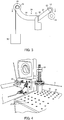
Fig. 1] Fig. 1 is a schematic view showing the configuration of a thread guide wear testing machine in outline according to an embodiment of the present invention; - [
Fig. 2] Fig. 2 is a perspective view showing a winding reel and a winding drum of the thread guide wear testing machine; - [
Fig. 3] Fig. 3 is a side view showing the configuration of contact retaining means of the thread guide wear testing machine in outline; and - [
Fig. 4] Fig. 4 is a perspective view showing tension adjusting means of the thread guide wear testing machine. - An embodiment of the present invention will be described in detail below.
- In
Fig. 1, 1 represents a thread guide wear testing machine. The thread guide wear testing machine 1 is used for a wear test of wearing atest piece 2 as a specimen by causing athread 3 to slide while thethread 3 is in contact with thetest piece 2. - The thread guide wear testing machine 1 includes a
winding unit 5 on which thethread 3 made of any material pulled out and fed from thread feeding means 4 is wound, and a guide unit 6 for guiding thethread 3 from the thread feeding means 4 toward thewinding unit 5. - The thread feeding means 4 has an outer peripheral surface around which the
thread 3 is wound, and allows pulling out of thewound thread 3 from a tip portion thereof. - The
winding unit 5 includes awinding reel 12 and a windingdrum 13 each rotatably arranged on top of abase 11 placed on a floor surface. - The winding
reel 12 has areel body 14 made of synthetic resin such as polyvinyl chloride, for example, and formed into what is called a conical shape with one side tapered down in an axis direction. Ashaft 15 is fixed in thereel body 14. Afirst arm 21 is attached in such a manner as to be capable of pivoting at atip portion 23 about abase portion 22 relative to thebase 11. Theshaft 15 is rotatably supported on the tip of thefirst arm 21 to make thereel body 14 rotatable about theshaft 15. - The
winding reel 12 is rotated while the tip portion of thethread 3 pulled out of the thread feeding means 4 is fixed to thereel body 14, thereby winding thethread 3 around an outer peripheral surface of thereel body 14. - The winding
drum 13 has adrum body 16 made of synthetic resin and formed into a cylindrical shape. Ashaft 17 is fixed in thedrum body 16. Theshaft 17 is rotatably supported on top of thebase 11 to make thedrum body 16 rotatable about theshaft 17. - The
winding drum 13 is arranged in such a manner that the axis direction of thedrum body 16 is slightly shifted from the axis direction of thereel body 14, and that an outer peripheral surface of thedrum body 16 is in contact with the outer peripheral surface of thereel body 14. With thedrum body 16 and thereel body 14 contacting each other in this way, rotating the windingdrum 13 using driving means such as a motor, for example, causes thereel body 14 contacting thedrum body 16 to further rotate in a direction opposite thedrum body 16. - As shown in
Fig. 2 , the outer peripheral surface of thedrum body 16 is provided with aguide groove 18 in which thethread 3 from the thread feeding means 4 can be engaged and through which the engagedthread 3 is guided to thereel body 14. - The
guide groove 18 extends in a shape tilted from a peripheral direction of thedrum body 16 and forms intersections on the outer peripheral surface. - With the
thread 3 from the thread feeding means 4 engaged in theguide groove 18 and with the tip portion of thethread 3 fixed to thereel body 14, rotating thedrum body 16 causes thereel body 14 to further rotate in a direction opposite thedrum body 16. In response to this rotation, thethread 3 is wound up on thereel body 14, guided along theguide groove 18 having the tilted shape, and wound around thereel body 14 so as to move back and forth sequentially in the axis direction of thereel body 14. - When the amount of the
thread 3 being wound up by thewinding reel 12 increases, thewinding reel 12 is lifted in a direction in which thewinding reel 12 is separated from thewinding drum 13. This makes a state of contact between thewinding reel 12 and thewinding drum 13 unstable to cause a rattle, for example. As a result, vibration occurring during winding of thethread 3 is increased. If the vibration is increased, the increased vibration is transmitted to thethread 3 to cause deviation of an angle of contact between thethread 3 and thetest piece 2, namely, a wear site. In this way, a wear state may be affected adversely. - In this regard, contact retaining means 24 of retaining a state of contact between the
winding reel 12 and the windingdrum 13 is provided. - As shown in
Fig. 3 , the contact retaining means 24 includes asecond arm 26 connected via aconnection 25 to thebase portion 22 of thefirst arm 21 to which thewinding reel 12 is attached. - The
second arm 26 is capable of pivoting at atip portion 28 about abase portion 27 connected to theconnection 25. Aweight 30 of a predetermined mass (8 kg, for example) is provided to thetip portion 28 of thesecond arm 26 via anattachment member 29. - The
first arm 21 and thesecond arm 26 are connected at theconnection 25 by means of the principle of leverage. More specifically, when a load is applied from theweight 30 in such a manner as to push down thetip portion 28 of thesecond arm 26, the applied load acts by means of the principle of leverage so as to depress thewinding reel 12 provided at thetip portion 23 of thefirst arm 21 toward thewinding drum 13 below thewinding reel 12 to press thewinding reel 12 against thewinding drum 13 in a direction in which thewinding reel 12 and thewinding drum 13 get closer to each other. In this way, a contact state is retained. - The guide unit 6 includes a
guide member 32 fixed on top of a fixing table 31 placed on a floor surface, andsupport members - The
thread 3 from the thread feeding means 4 is engaged with theguide member 32 and thesupport members unit 5, engaged with aguide member 36 provided at thebase 11, and then guided toward the windingreel 12 and the windingdrum 13. More specifically, thethread 3 fed from the thread feeding means 4 is changed in direction at theguide member 32 toward thesupport member 33, changed in direction at thesupport member 33 toward thesupport member 34, changed in direction at thesupport member 34 toward theguide member 36, changed in direction at theguide member 36 toward the windingdrum 13, passed through theguide groove 18 of the windingdrum 13, and then wound around the windingreel 12. - Specimen holding means 35 to which a load cell not shown in the drawings is fixed to the fixing table 31. The
test piece 2 is fixed to be adjustable in position to the specimen holding means 35. - The
test piece 2 fixed in this way to the specimen holding means 35 is retained in a state of contacting thethread 3 between thesupport members - By winding up the
thread 3 on the windingreel 12 while thetest piece 2 is in contact with thethread 3, thethread 3 from the thread feeding means 4 is moved in one direction toward the windingreel 12 to cause sliding motion under a predetermined load between thethread 3 and thetest piece 2. - As shown in
Fig. 4 , changing the positions of thesupport members thread 3 with which thetest piece 2 is in contact between the thread feeding means 4 and the windingreel 12. Namely, a plurality ofopenings 37 and thesupport members - A thread guide wear testing method implemented by using the thread guide wear testing machine 1 will be described next.
- First, the
thread 3 is pulled out of the thread feeding means 4. Next, the pulled-outthread 3 is engaged with theguide member 32, thesupport members guide member 36 sequentially, and then fixed to the windingreel 12 through theguide groove 18 of the windingdrum 13. In this way, thethread 3 from the thread feeding means 4 is wound around the windingreel 12. - Further, the
test piece 2 is fixed to the specimen holding means 35. If necessary, the attachment positions of thesupport members thread 3 and adjust a load of pressing thetest piece 2 against thethread 3. - Moreover, the
weight 30 is attached to theattachment member 29 of thesecond arm 26, and a load is applied so as to press the windingreel 12 toward the windingdrum 13. - Then, a rotation speed of the winding
drum 13 is set in such a manner as to provide a predetermined feed speed. Further, a duration of rotation of the windingdrum 13 is set in such a manner as to provide a predetermined wear distance. - Then, the winding
drum 13 is rotated to cause sliding motion of thethread 3 relative to thetest piece 2, thereby wearing thetest piece 2 using the friction of thethread 3. - After the wear test is finished, the amount of wear is measured by measuring weight change or volume change. For example, the shape of the
test piece 2 is transferred to replica resin, and a wear part is observed with a laser microscope. Further, a specific wear amount is calculated by measuring the depth of a wear track, etc. through the observation with the laser microscope, thereby evaluating the wear resistance of thetest piece 2 against thethread 3. - According to the foregoing embodiment, adjusting the attachment positions of the
support members thread 3 to make sliding motion while contacting thetest piece 2. Thus, a wear state can be set properly in response to a raw material for thetest piece 2 or the type of thethread 3, so that the occurrence of trouble such as damage or break of thethread 3 is prevented during implementation of the wear test. - The wear test is conducted while a load is applied using the
weight 30 in such a manner as to press the windingreel 12 toward the windingdrum 13. Thus, even if winding of thethread 3 using the windingreel 12 proceeds further to increase the thickness of thethread 3 wound around the outer peripheral surface of thereel body 14, a state of contact is still retained between the windingreel 12 and the windingdrum 13. In this way, a state of winding of thethread 3 using the windingreel 12 is stabilized, and trouble resulting from progress of the winding such as deviation of thethread 3 is unlikely to occur. This makes it possible to prevent change in tension on thethread 3 or change in a load of pressing thetest piece 2 against thethread 3 to be caused by such trouble to allow development of wear under constant test conditions. - As a result, even if the wear test using the
thread 3 is conducted for a relatively long period of time, the wear test can still be conducted stably. - Even with a test piece of some millimeters square considerably small as a test piece for the wear test, the wear test can still be conducted.
- Moreover, as a feed speed of a thread, a load on a test piece, tension on the thread, and the type of the thread are changeable, an accelerated test can be conducted by changing these conditions appropriately.
- According to the foregoing embodiment, the tension adjusting means is configured to adjust tension on the
thread 3 by changing the attachment positions of thesupport members test piece 2 is fixed. However, this is not the only configuration but the tension adjusting means can be changed appropriately to any configuration allowing adjustment of tension on thethread 3 between the thread feeding means 4, the windingreel 12, and the windingdrum 13. - The contact retaining means 24 is configured to retain a contact state by means of the principle of leverage by applying a load in such a manner as to press the winding
reel 12 toward the windingdrum 13 using theweight 30. However, this is not the only configuration but the contact retaining means 24 may be configured in any way, as long as at least one of the windingreel 12 and the windingdrum 13 is pressed in such a manner as to retain a state of contact between the windingreel 12 and the windingdrum 13. - The present invention is applicable to a test for wear of a steel sheet with a fiber such as a thread.
-
- 1
- Thread guide wear testing machine
- 2
- Test piece as specimen
- 3
- Thread
- 4
- Thread feeding means
- 12
- Winding reel
- 13
- Winding drum
- 18
- Guide groove
- 24
- Contact retaining means
- 35
- Specimen holding means
Claims (3)
- A thread guide wear testing machine for wearing a specimen by causing a thread to slide while the thread is in contact with the specimen, the thread guide wear testing machine comprising:thread feeding means;a winding reel usable for winding a thread thereon fed from the thread feeding means;a winding drum provided in contact with an outer peripheral surface of the winding reel and guiding the thread fed from the thread feeding means to the winding reel;specimen holding means provided on a path of the thread fed from the thread feeding means and moving while being wound on the winding reel, the specimen holding means holding the specimen in a state of contacting the thread under a predetermined load;tension adjusting means for adjusting tension on the thread; andcontact retaining means for retaining a state of contact between the winding reel and the winding drum.
- The thread guide wear testing machine according to claim 1, wherein
the winding drum has an outer peripheral surface provided with a guide groove through which the thread fed from the thread feeding means is guided to the winding reel, and
the guide groove has a shape tilted from a peripheral direction of the winding drum for winding the thread around the winding reel sequentially in an axis direction of the winding reel. - A thread guide wear test method implemented by using the thread guide wear testing machine according to claim 1 or 2, wherein
the thread fed from the thread feeding means is moved while being wound on the winding reel, and
the specimen is held while being brought into contact with the moving thread under a predetermined load, and the specimen and the thread are caused to slide relative to each other, thereby wearing the specimen.
Applications Claiming Priority (1)
| Application Number | Priority Date | Filing Date | Title |
|---|---|---|---|
| PCT/JP2017/030618 WO2019038925A1 (en) | 2017-08-25 | 2017-08-25 | Filament path wear tester and filament path wear testing method |
Publications (2)
| Publication Number | Publication Date |
|---|---|
| EP3674681A1 true EP3674681A1 (en) | 2020-07-01 |
| EP3674681A4 EP3674681A4 (en) | 2021-03-10 |
Family
ID=65438540
Family Applications (1)
| Application Number | Title | Priority Date | Filing Date |
|---|---|---|---|
| EP17922494.4A Withdrawn EP3674681A4 (en) | 2017-08-25 | 2017-08-25 | FILAMENT PATH WEAR TESTER AND FILAMENT PATH WEAR TEST METHOD |
Country Status (5)
| Country | Link |
|---|---|
| US (1) | US20200225136A1 (en) |
| EP (1) | EP3674681A4 (en) |
| KR (1) | KR20200042901A (en) |
| CN (1) | CN111033214A (en) |
| WO (1) | WO2019038925A1 (en) |
Families Citing this family (3)
| Publication number | Priority date | Publication date | Assignee | Title |
|---|---|---|---|---|
| CN113651175B (en) * | 2021-08-13 | 2023-05-30 | 江苏鼎顺医疗用品有限公司 | Braiding and winding integrated ear belt machine |
| CN116429608A (en) * | 2023-03-16 | 2023-07-14 | 铁四院武汉检测技术有限公司 | Device and method for measuring wear-resistant hardness coefficient of rock and stone |
| CN120363513B (en) * | 2025-06-26 | 2025-08-29 | 太原理工大学 | Mechanical tension-controllable fiber unreeling device and fiber winding method |
Family Cites Families (13)
| Publication number | Priority date | Publication date | Assignee | Title |
|---|---|---|---|---|
| CH402693A (en) * | 1963-06-08 | 1965-11-15 | Schweiter Ag Maschf | Thread guide device at a winding station |
| DE2553892C3 (en) * | 1975-11-29 | 1979-10-04 | Skf Kugellagerfabriken Gmbh, 8720 Schweinfurt | Take-off device for an open-end spinning machine |
| JP2959824B2 (en) * | 1990-10-03 | 1999-10-06 | 富士通株式会社 | Method for evaluating wear resistance of magnetic disk media surface |
| JPH11286852A (en) | 1998-03-31 | 1999-10-19 | Nisshin Steel Co Ltd | Highly durable reed dent comprising multi-phase tissue stainless steel raw material |
| JP4825381B2 (en) | 2001-09-28 | 2011-11-30 | 日本冶金工業株式会社 | Stainless steel material excellent in wear resistance and corrosion resistance and method for producing the same |
| DE10205435C1 (en) * | 2002-02-08 | 2003-08-14 | Fraunhofer Ges Forschung | Method and device for determining the wear resistance of a surface |
| JP5190703B2 (en) * | 2008-12-24 | 2013-04-24 | 村田機械株式会社 | Yarn winding device and automatic winder |
| JP2011195216A (en) * | 2010-03-17 | 2011-10-06 | Murata Machinery Ltd | Yarn winding machine |
| CZ303650B6 (en) * | 2011-09-21 | 2013-01-23 | VÚTS, a.s. | Method of and apparatus for determining surface wear of textile machine components by a moving linear textile material |
| JP2013142611A (en) * | 2012-01-11 | 2013-07-22 | Sumitomo Wiring Syst Ltd | Wear resistance test method for wire coating material |
| JP2013154991A (en) * | 2012-01-30 | 2013-08-15 | Murata Machinery Ltd | Yarn winding machine and yarn winding method |
| US9341555B2 (en) * | 2012-05-24 | 2016-05-17 | Scott H Norman | Abrasion wear tester |
| JP6726491B2 (en) * | 2016-03-09 | 2020-07-22 | 日鉄日新製鋼株式会社 | Yarn path abrasion tester and yarn path abrasion test method |
-
2017
- 2017-08-25 CN CN201780093939.9A patent/CN111033214A/en active Pending
- 2017-08-25 KR KR1020207004860A patent/KR20200042901A/en not_active Ceased
- 2017-08-25 US US16/641,539 patent/US20200225136A1/en not_active Abandoned
- 2017-08-25 EP EP17922494.4A patent/EP3674681A4/en not_active Withdrawn
- 2017-08-25 WO PCT/JP2017/030618 patent/WO2019038925A1/en not_active Ceased
Also Published As
| Publication number | Publication date |
|---|---|
| WO2019038925A1 (en) | 2019-02-28 |
| EP3674681A4 (en) | 2021-03-10 |
| KR20200042901A (en) | 2020-04-24 |
| CN111033214A (en) | 2020-04-17 |
| US20200225136A1 (en) | 2020-07-16 |
Similar Documents
| Publication | Publication Date | Title |
|---|---|---|
| EP3674681A1 (en) | Filament path wear tester and filament path wear testing method | |
| EP3061857B1 (en) | Filament feeder for torchon lace machine | |
| JP2009541601A (en) | Device for separating yarn from a layer of yarn, method for operating the device, and use of the device | |
| JP7467052B2 (en) | Method and apparatus for rotating a package in a winding device - Patents.com | |
| JPH0716830B2 (en) | A device that circulates the electrodes of a spark corrosion cutter around the wheel. | |
| CN101929006B (en) | Free end revolving cup spinning machine | |
| EP3088577A1 (en) | Device and method for determining the diameter of a thread balloon, formed by a running thread at the workstation of a textile machine | |
| JP6726491B2 (en) | Yarn path abrasion tester and yarn path abrasion test method | |
| Ebel et al. | Yarn damage during braiding of reinforcement fibers for composites | |
| CN1765723B (en) | Device for optimizing yarn withdrawing of winder of automatic cross-winding apparatus | |
| JP2002145527A (en) | Winder for particularly sensitive winding materials | |
| JP2006162301A (en) | Abrasion tester | |
| US10206675B2 (en) | Method and apparatus for fabricating self-retaining sutures with calibration | |
| TW201913066A (en) | Thread path wear testing machine and thread path wear testing method | |
| TWI482677B (en) | Tension balance control device | |
| JP5364482B2 (en) | Yarn winding machine and winding method of yarn | |
| US2205579A (en) | Testing machine | |
| JPS60143935A (en) | Wind-up machine for forming cylindrical structure by windingup synthetic substance reinforced by fiber | |
| CN106436071A (en) | Coil thread detector | |
| US20110114780A1 (en) | Calibrated yarn tensioner, textile machine, and method for tensioning a continuously running yarn | |
| US5806744A (en) | Apparatus for feeding and tensioning threads in a textile machine | |
| JP6935727B2 (en) | Identification thread attachment device | |
| US1110015A (en) | Automatic feeding device. | |
| US399754A (en) | Testing-machine | |
| US692195A (en) | Machine for unraveling knit goods. |
Legal Events
| Date | Code | Title | Description |
|---|---|---|---|
| STAA | Information on the status of an ep patent application or granted ep patent |
Free format text: STATUS: THE INTERNATIONAL PUBLICATION HAS BEEN MADE |
|
| PUAI | Public reference made under article 153(3) epc to a published international application that has entered the european phase |
Free format text: ORIGINAL CODE: 0009012 |
|
| STAA | Information on the status of an ep patent application or granted ep patent |
Free format text: STATUS: REQUEST FOR EXAMINATION WAS MADE |
|
| 17P | Request for examination filed |
Effective date: 20200214 |
|
| AK | Designated contracting states |
Kind code of ref document: A1 Designated state(s): AL AT BE BG CH CY CZ DE DK EE ES FI FR GB GR HR HU IE IS IT LI LT LU LV MC MK MT NL NO PL PT RO RS SE SI SK SM TR |
|
| AX | Request for extension of the european patent |
Extension state: BA ME |
|
| DAV | Request for validation of the european patent (deleted) | ||
| DAX | Request for extension of the european patent (deleted) | ||
| RAP1 | Party data changed (applicant data changed or rights of an application transferred) |
Owner name: NIPPON STEEL CORPORATION |
|
| A4 | Supplementary search report drawn up and despatched |
Effective date: 20210208 |
|
| RIC1 | Information provided on ipc code assigned before grant |
Ipc: B65H 54/28 20060101ALI20210202BHEP Ipc: B65H 54/52 20060101ALI20210202BHEP Ipc: G01M 13/00 20190101ALN20210202BHEP Ipc: B65H 57/24 20060101ALI20210202BHEP Ipc: B65H 57/14 20060101ALI20210202BHEP Ipc: B65H 57/00 20060101ALI20210202BHEP Ipc: G01N 3/56 20060101AFI20210202BHEP |
|
| STAA | Information on the status of an ep patent application or granted ep patent |
Free format text: STATUS: THE APPLICATION IS DEEMED TO BE WITHDRAWN |
|
| 18D | Application deemed to be withdrawn |
Effective date: 20210908 |