EP3674627A1 - Vehicle air conditioning apparatus - Google Patents
Vehicle air conditioning apparatus Download PDFInfo
- Publication number
- EP3674627A1 EP3674627A1 EP19218445.5A EP19218445A EP3674627A1 EP 3674627 A1 EP3674627 A1 EP 3674627A1 EP 19218445 A EP19218445 A EP 19218445A EP 3674627 A1 EP3674627 A1 EP 3674627A1
- Authority
- EP
- European Patent Office
- Prior art keywords
- refrigerant
- bypass passage
- accumulator
- flow
- compressor
- Prior art date
- Legal status (The legal status is an assumption and is not a legal conclusion. Google has not performed a legal analysis and makes no representation as to the accuracy of the status listed.)
- Withdrawn
Links
Images






Classifications
-
- F—MECHANICAL ENGINEERING; LIGHTING; HEATING; WEAPONS; BLASTING
- F25—REFRIGERATION OR COOLING; COMBINED HEATING AND REFRIGERATION SYSTEMS; HEAT PUMP SYSTEMS; MANUFACTURE OR STORAGE OF ICE; LIQUEFACTION SOLIDIFICATION OF GASES
- F25B—REFRIGERATION MACHINES, PLANTS OR SYSTEMS; COMBINED HEATING AND REFRIGERATION SYSTEMS; HEAT PUMP SYSTEMS
- F25B43/00—Arrangements for separating or purifying gases or liquids; Arrangements for vaporising the residuum of liquid refrigerant, e.g. by heat
- F25B43/006—Accumulators
-
- F—MECHANICAL ENGINEERING; LIGHTING; HEATING; WEAPONS; BLASTING
- F25—REFRIGERATION OR COOLING; COMBINED HEATING AND REFRIGERATION SYSTEMS; HEAT PUMP SYSTEMS; MANUFACTURE OR STORAGE OF ICE; LIQUEFACTION SOLIDIFICATION OF GASES
- F25B—REFRIGERATION MACHINES, PLANTS OR SYSTEMS; COMBINED HEATING AND REFRIGERATION SYSTEMS; HEAT PUMP SYSTEMS
- F25B49/00—Arrangement or mounting of control or safety devices
- F25B49/02—Arrangement or mounting of control or safety devices for compression type machines, plants or systems
-
- F—MECHANICAL ENGINEERING; LIGHTING; HEATING; WEAPONS; BLASTING
- F25—REFRIGERATION OR COOLING; COMBINED HEATING AND REFRIGERATION SYSTEMS; HEAT PUMP SYSTEMS; MANUFACTURE OR STORAGE OF ICE; LIQUEFACTION SOLIDIFICATION OF GASES
- F25B—REFRIGERATION MACHINES, PLANTS OR SYSTEMS; COMBINED HEATING AND REFRIGERATION SYSTEMS; HEAT PUMP SYSTEMS
- F25B5/00—Compression machines, plants or systems, with several evaporator circuits, e.g. for varying refrigerating capacity
- F25B5/02—Compression machines, plants or systems, with several evaporator circuits, e.g. for varying refrigerating capacity arranged in parallel
-
- F—MECHANICAL ENGINEERING; LIGHTING; HEATING; WEAPONS; BLASTING
- F25—REFRIGERATION OR COOLING; COMBINED HEATING AND REFRIGERATION SYSTEMS; HEAT PUMP SYSTEMS; MANUFACTURE OR STORAGE OF ICE; LIQUEFACTION SOLIDIFICATION OF GASES
- F25B—REFRIGERATION MACHINES, PLANTS OR SYSTEMS; COMBINED HEATING AND REFRIGERATION SYSTEMS; HEAT PUMP SYSTEMS
- F25B6/00—Compression machines, plants or systems, with several condenser circuits
- F25B6/02—Compression machines, plants or systems, with several condenser circuits arranged in parallel
-
- F—MECHANICAL ENGINEERING; LIGHTING; HEATING; WEAPONS; BLASTING
- F25—REFRIGERATION OR COOLING; COMBINED HEATING AND REFRIGERATION SYSTEMS; HEAT PUMP SYSTEMS; MANUFACTURE OR STORAGE OF ICE; LIQUEFACTION SOLIDIFICATION OF GASES
- F25B—REFRIGERATION MACHINES, PLANTS OR SYSTEMS; COMBINED HEATING AND REFRIGERATION SYSTEMS; HEAT PUMP SYSTEMS
- F25B6/00—Compression machines, plants or systems, with several condenser circuits
- F25B6/04—Compression machines, plants or systems, with several condenser circuits arranged in series
-
- F—MECHANICAL ENGINEERING; LIGHTING; HEATING; WEAPONS; BLASTING
- F25—REFRIGERATION OR COOLING; COMBINED HEATING AND REFRIGERATION SYSTEMS; HEAT PUMP SYSTEMS; MANUFACTURE OR STORAGE OF ICE; LIQUEFACTION SOLIDIFICATION OF GASES
- F25B—REFRIGERATION MACHINES, PLANTS OR SYSTEMS; COMBINED HEATING AND REFRIGERATION SYSTEMS; HEAT PUMP SYSTEMS
- F25B2339/00—Details of evaporators; Details of condensers
- F25B2339/04—Details of condensers
- F25B2339/047—Water-cooled condensers
-
- F—MECHANICAL ENGINEERING; LIGHTING; HEATING; WEAPONS; BLASTING
- F25—REFRIGERATION OR COOLING; COMBINED HEATING AND REFRIGERATION SYSTEMS; HEAT PUMP SYSTEMS; MANUFACTURE OR STORAGE OF ICE; LIQUEFACTION SOLIDIFICATION OF GASES
- F25B—REFRIGERATION MACHINES, PLANTS OR SYSTEMS; COMBINED HEATING AND REFRIGERATION SYSTEMS; HEAT PUMP SYSTEMS
- F25B2400/00—Component parts or details not otherwise provided for in this subclass
- F25B2400/04—Refrigeration circuit bypassing means
-
- F—MECHANICAL ENGINEERING; LIGHTING; HEATING; WEAPONS; BLASTING
- F25—REFRIGERATION OR COOLING; COMBINED HEATING AND REFRIGERATION SYSTEMS; HEAT PUMP SYSTEMS; MANUFACTURE OR STORAGE OF ICE; LIQUEFACTION SOLIDIFICATION OF GASES
- F25B—REFRIGERATION MACHINES, PLANTS OR SYSTEMS; COMBINED HEATING AND REFRIGERATION SYSTEMS; HEAT PUMP SYSTEMS
- F25B2500/00—Problems to be solved
- F25B2500/12—Sound
-
- F—MECHANICAL ENGINEERING; LIGHTING; HEATING; WEAPONS; BLASTING
- F25—REFRIGERATION OR COOLING; COMBINED HEATING AND REFRIGERATION SYSTEMS; HEAT PUMP SYSTEMS; MANUFACTURE OR STORAGE OF ICE; LIQUEFACTION SOLIDIFICATION OF GASES
- F25B—REFRIGERATION MACHINES, PLANTS OR SYSTEMS; COMBINED HEATING AND REFRIGERATION SYSTEMS; HEAT PUMP SYSTEMS
- F25B2500/00—Problems to be solved
- F25B2500/26—Problems to be solved characterised by the startup of the refrigeration cycle
-
- F—MECHANICAL ENGINEERING; LIGHTING; HEATING; WEAPONS; BLASTING
- F25—REFRIGERATION OR COOLING; COMBINED HEATING AND REFRIGERATION SYSTEMS; HEAT PUMP SYSTEMS; MANUFACTURE OR STORAGE OF ICE; LIQUEFACTION SOLIDIFICATION OF GASES
- F25B—REFRIGERATION MACHINES, PLANTS OR SYSTEMS; COMBINED HEATING AND REFRIGERATION SYSTEMS; HEAT PUMP SYSTEMS
- F25B2600/00—Control issues
- F25B2600/25—Control of valves
- F25B2600/2507—Flow-diverting valves
-
- F—MECHANICAL ENGINEERING; LIGHTING; HEATING; WEAPONS; BLASTING
- F25—REFRIGERATION OR COOLING; COMBINED HEATING AND REFRIGERATION SYSTEMS; HEAT PUMP SYSTEMS; MANUFACTURE OR STORAGE OF ICE; LIQUEFACTION SOLIDIFICATION OF GASES
- F25B—REFRIGERATION MACHINES, PLANTS OR SYSTEMS; COMBINED HEATING AND REFRIGERATION SYSTEMS; HEAT PUMP SYSTEMS
- F25B2700/00—Sensing or detecting of parameters; Sensors therefor
- F25B2700/21—Temperatures
- F25B2700/2106—Temperatures of fresh outdoor air
-
- F—MECHANICAL ENGINEERING; LIGHTING; HEATING; WEAPONS; BLASTING
- F25—REFRIGERATION OR COOLING; COMBINED HEATING AND REFRIGERATION SYSTEMS; HEAT PUMP SYSTEMS; MANUFACTURE OR STORAGE OF ICE; LIQUEFACTION SOLIDIFICATION OF GASES
- F25B—REFRIGERATION MACHINES, PLANTS OR SYSTEMS; COMBINED HEATING AND REFRIGERATION SYSTEMS; HEAT PUMP SYSTEMS
- F25B2700/00—Sensing or detecting of parameters; Sensors therefor
- F25B2700/21—Temperatures
- F25B2700/2113—Temperatures of a suction accumulator
Definitions
- the present disclosure relates to a vehicle air conditioning apparatus including a refrigeration cycle having an accumulator.
- Patent Literature 1 aims to suppress the refrigerant coming to a boil by driving a stirring device utilizing the flow of refrigerant flowing into the accumulator and thus stirring a liquid-phase refrigerant accumulated inside the accumulator.
- a vent is provided in an upper portion of a refrigerant outflow pipe inside the accumulator, short-circuiting a gas-phase refrigerant inside the accumulator (for example, refer to Patent Literature 2) .
- Patent Literature 1 In the technology of Patent Literature 1, however, there is a disadvantage in that a stirring device 90 is installed, thus leading to a complexity in the internal structure of the accumulator.
- Patent Literature 2 it is necessary, from a liquid-phase refrigerant accumulated in a lower portion inside the accumulator, to suck out a lubricant dissolved therein, and it is essential for the refrigerant outflow pipe extending to the lower portion inside the accumulator to exert a certain suction power at the lower side leading end, so that a vent such as shown by sign 17 in Patent Literature 2 cannot be set to be indiscriminately large in size.
- the present disclosure has for its object to provide a vehicle air conditioning apparatus having a refrigeration cycle, which, while fully performing a desired temperature control function required for the vehicle air conditioning apparatus, can avoid an excessively depressurized state inside an accumulator.
- the present inventors after their earnest studies, have found out that an abnormal noise due to bumping can be suppressed by providing a bypass passage which connects outside the accumulator a refrigerant inlet pipe, which causes a refrigerant circulating through a refrigeration cycle to flow into an accumulator, and a refrigerant outlet pipe, which causes the refrigerant to flow out from the accumulator, thus short-circuiting the refrigerant, enabling the refrigerant to circulate, and has completed the present invention.
- the vehicle air conditioning apparatus includes a refrigeration cycle which includes at least a compressor, an outdoor heat exchanger, an expanding device, an evaporator, and an accumulator and in which these elements are connected in this order by piping; a bypass passage which connects outside the accumulator a refrigerant inlet pipe, which causes a refrigerant circulating through the refrigeration cycle to flow into the accumulator, and a refrigerant outlet pipe, which causes the refrigerant to flow out from the accumulator, thus short-circuiting the refrigerant, enabling the refrigerant to circulate; a valve device which, being provided in the bypass passage, has an opening/closing function; and a control device which controls at least the compressor and the valve device.
- the valve device is an on/off valve which allows or blocks the flow of the refrigerant in the bypass passage.
- the flow of the refrigerant in the bypass passage can be controlled with a simple structure.
- valve device is a three-way valve which is disposed at the confluence of the bypass passage and the refrigerant outlet pipe.
- the flow of the refrigerant in the bypass passage can be controlled with a simple structure.
- a refrigerant temperature detection unit which can detect the temperature of a liquid-phase refrigerant inside the accumulator, wherein the compressor is of an electric type, and wherein the control device starts the compressor at a specified rotation speed and sets the state in which the flow of the refrigerant in the bypass passage is allowed by the valve device, subsequently, calculates an estimated superheat degree T_est of a gas-phase refrigerant inside the accumulator, which is obtained when the flow of the refrigerant in the bypass passage is blocked, from the specified rotation speed of the compressor and from temperature information obtained from the refrigerant temperature detection unit, compares the estimated superheat degree T_est and a predetermined threshold superheat degree T_def, and when the estimated superheat degree T_est falls below the threshold superheat degree T_def, causes the valve device to block the flow of the refrigerant in the bypass passage. It is possible to estimate the time at which to close the valve device and
- a temperature sensor portion of the refrigerant temperature detection unit is disposed on the lower side of the center in the internal space of the accumulator or on the outer bottom surface of the accumulator. It is possible to more accurately estimate the time at which to close the valve device, and as a result, it is possible to more accurately suppress an occurrence of bumping.
- the control device when the compressor is started, sets the state in which the flow of the refrigerant in the bypass passage is allowed by the valve device, and subsequently, after a predetermined time has passed, sets the state in which the flow of the refrigerant in the bypass passage is blocked by the valve device. It is possible, even without providing the refrigerant temperature detection unit, to accurately suppress an occurrence of bumping with the configuration remaining simple.
- the vehicle air conditioning apparatus it is preferable to further include a vehicle exterior temperature detection unit, wherein the control device, when the compressor is started, sets the state in which the flow of the refrigerant in the bypass passage is allowed by the valve device when a vehicle exterior temperature obtained from the vehicle exterior temperature detection unit is lower than a predetermined temperature, and sets the state in which the flow of the refrigerant in the bypass passage is blocked by the valve device when the vehicle exterior temperature is equal to or higher than the predetermined temperature. It is possible, by using the vehicle exterior temperature detection unit, to accurately suppress an occurrence of bumping with the configuration remaining simple.
- the vehicle air conditioning apparatus having the refrigeration cycle, which, while fully performing the desired temperature control function required for the vehicle air conditioning apparatus, can avoid the excessively depressurized state inside the accumulator.
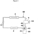
- the vehicle air conditioning apparatus includes a refrigeration cycle 80, which includes at least a compressor 6, an outdoor heat exchanger 4, an expanding device 12, an evaporator 3, and an accumulator 10 and in which these elements are connected in this order by piping, a bypass passage 43, which connects outside the accumulator 10 a refrigerant inlet pipe 41, which causes a refrigerant circulating through the refrigeration cycle 80 to flow into the accumulator 10, and a refrigerant outlet pipe 42, which causes the refrigerant to flow out from the accumulator 10, thus short-circuiting the refrigerant, enabling the refrigerant to circulate, a valve device 40 which, being provided in the bypass passage 43, has an opening/closing function, and a control device 23 which controls at least the compressor 6 and the valve device 40.
- a refrigeration cycle 80 which includes at least a compressor 6, an outdoor heat exchanger 4, an expanding device 12, an evaporator 3, and an accumulator 10 and in which these elements are connected in this order by piping
- the basic configuration of the refrigeration cycle for cooling includes the compressor 6, the outdoor heat exchanger 4, the expanding device 12, the evaporator 3, and the accumulator 10, as shown in Fig. 1 .
- the compressor 6 sucks in and compresses the refrigerant.
- the compressor 6 is rotary driven by a not-shown vehicle driving engine via a pulley 63, a belt, and the like.
- a variable capacity compressor or a fixed capacity compressor may be used.
- the capability to discharge the refrigerant can be adjusted by adjusting the rotation speed of an electric motor.
- the use of the electric compressor can obviate the necessity of the connection with the vehicle driving engine via the belt and the like.
- a liquid refrigerant condensed in the outdoor heat exchanger 4 is next reduced in pressure to a low pressure in the expanding device 12, turning into a misty, gas-liquid two-phase state.
- the expanding device 12 is formed of a fixed aperture, such as an orifice or a nozzle, or an appropriate variable aperture.
- the low-pressure refrigerant reduced in pressure, in the evaporator 3 absorbs heat from the air blown by a not-shown air conditioning blower and evaporates.
- the evaporator 3 is disposed in a not-shown air-conditioner casing, and cold air cooled in the evaporator 3, after being adjusted in temperature by a not-shown heater core section, is blown out into a vehicle interior.
- the accumulator 10 plays the role of separating the refrigerant having flowed out from the evaporator 3 into a gas-phase refrigerant and a liquid-phase refrigerant, storing the liquid-phase refrigerant, and causing the gas-phase refrigerant to be sucked into the compressor 6.
- the accumulator 10 also plays the role of causing oil, which is dissolved in the liquid refrigerant accumulating in a tank bottom portion, to be sucked into the compressor 6.
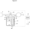
- a refrigerant 44 shown in Fig. 2 is a refrigerant which has flowed out from the evaporator 3 and is in the gas-liquid two-phase state.
- the refrigerant 44 having passed through the refrigerant inlet pipe 41 connected to the evaporator 3 flows into the internal space of a tank 45 through an inflow opening 46 provided in the tank 45.
- An accumulated liquid-phase refrigerant 47 and a gas-phase refrigerant 48 exist in the internal space of the tank 45.
- the refrigerant 44 in the gas-liquid two-phase state is separated by a gas-liquid separator 52 into the gas-phase refrigerant and the liquid-phase refrigerant.
- the gas-phase refrigerant 48 is sent to the compressor 6 through the refrigerant outlet pipe 42 connected to an outflow opening 49 provided in the tank 45.
- the bypass passage 43 connects outside the accumulator 10 the refrigerant inlet pipe 41 and the refrigerant outlet pipe 42 which causes the refrigerant to flow out from the accumulator 10, thus short-circuiting the refrigerant, enabling the refrigerant to circulate.
- the valve device 40 for carrying out the opening/closing of the bypass passage 43 is provided in the bypass passage 43.
- the flow of refrigerant in the bypass passage 43 is "allowed" or "blocked” by the valve device 40. It is preferable here that the valve device 40 is an on/off valve such as shown in Fig. 2 .
- the on/off valve can control the flow of refrigerant in the bypass passage 43 with a simple structure.
- the flow of refrigerant in the bypass passage is "allowed".
- the refrigerant inlet pipe 41 and the refrigerant outlet pipe 42 are not closed at this time, the refrigerant can flow into the accumulator 10, but airflow resistance is lower when the refrigerant flows in the bypass passage 43 than when the refrigerant flows in the accumulator 10, so that the refrigerant flows dominantly in the bypass passage 43.
- the pressure in the bypass passage 43 and the pressure in the accumulator 10 are spontaneously approximated to each other.
- the on/off valve is closed, the flow of refrigerant in the bypass passage is "blocked", and the refrigerant flows into the accumulator 10.
- the valve device 40 is a three-way valve which is disposed at the confluence of the bypass passage 43 and the refrigerant outlet pipe 42.
- the three-way valve can control the flow of refrigerant in the bypass passage 43 with a simple structure. That is, when the three-way valve opens the bypass passage and closes the refrigerant outlet pipe 42, the flow of refrigerant in the bypass passage is "allowed". At this time, the refrigerant outlet pipe 42 is closed, and so the refrigerant does not flow into the accumulator 10. However, as the refrigerant inlet pipe 41 is not closed, the pressure in the bypass passage 43 and the pressure in the accumulator 10 are spontaneously approximated to each other. On the other hand, when the three-way valve closes the bypass passage and opens the refrigerant outlet pipe 42, the flow of refrigerant in the bypass passage is "blocked", and the refrigerant flows into the accumulator 10.
- valve device 40 acts equally in both “allowing” and “blocking" the flow of refrigerant in the bypass passage 43, as heretofore described.
- a refrigerant temperature detection unit 50 which can detect the temperature of the liquid-phase refrigerant 47 inside the accumulator 10. It is preferable here that a temperature sensor portion of the refrigerant temperature detection unit 50 is disposed on the lower side of the center in the internal space of the accumulator 10 or on the outer bottom surface of the accumulator 10. The temperature sensor portion is disposed in such a place, and thereby the temperature of the liquid-phase refrigerant 47 can be accurately detected.
- Fig. 2 shows the mode in which the temperature sensor portion of the refrigerant temperature detection unit 50 is disposed on the outer bottom surface of the accumulator 10.
- the temperature sensor portion of the refrigerant temperature detection unit 50 when being disposed on the lower side of the center in the internal space of the accumulator 10, can accurately measure the liquid temperature of the liquid-phase refrigerant 47 even in the event that the amount of liquid-phase refrigerant 47 accumulated in the accumulator 10, which can fluctuate, fluctuates.
- a vehicle exterior temperature detection unit 51 In the vehicle air conditioning apparatus according to the present embodiment, it is preferable, as shown in Fig. 4 , to further have a vehicle exterior temperature detection unit 51. In the modes shown in Figs. 2 and 3 , too, it is preferable to further have the vehicle exterior temperature detection unit 51.
- the refrigerant boils inside the accumulator 10 immediately after the compressor 6 is started, and although depending also on what the rotation speed of the compressor is, an abnormal noise is generally more apt to occur under the condition that the vehicle exterior temperature is moderate (for example, 20°C) or lower (for example, 10°C) than under the condition that it is relatively high (for example, 35°C), so that the timing with which to operate opening/closing of the valve device 40 can be accurately adjusted by comprehending the vehicle exterior temperature.
- the control device 23 controls whether the valve device 40 is to "allow” or “block” the flow of refrigerant in the bypass passage 43. For example, the control device 23 controls switching between opening and closing the on/off valve. Also, the control device 23 controls the switching of the three-way valve between both opening the bypass passage 43 and closing the refrigerant outlet pipe 42 and both closing the bypass passage 43 and opening the refrigerant outlet pipe 42. Furthermore, the control device 23 carries out the control of the operation of the compressor 6. For example, when the compressor 6 is an electric compressor, the control device 23 specifies the rotation speed of the electric compressor, and the electric compressor is driven so as to achieve the specified rotation speed. Also, the control device 23, in addition to carrying out the control of the valve device 40 and the compressor 6, may carry out the control of another device.
- control device 23 may obtain information from each kind of sensor, for example, may obtain information on the temperature of the liquid-phase refrigerant inside the accumulator from the refrigerant temperature detection unit 50. Furthermore, the control device 23 may obtain information on the vehicle exterior temperature from the vehicle exterior temperature detection unit 51.
- the bypass passage 43 and the valve device 40 may be applied not only to a simple cooling refrigeration cycle (a first example of the refrigeration cycle), but to a refrigeration cycle which enables dehumidification heating.
- the bypass passage 43 and the valve device 40 may be applied, for example, to a vehicle air conditioning apparatus disclosed in International Publication WO 2013/035130 .
- the bypass passage 43 and the valve device 40 can be applied to the apparatus described in Fig. 1 , 5 , 6 , or 7 of the same publication.
- Figs. 5A and 5B show schematic diagrams of a second example of the configuration of the refrigeration cycle in the vehicle air conditioning apparatus according to the present embodiment.
- the second example of the configuration of the refrigeration cycle is an example in which the bypass passage 43 and the valve device 40 are applied to the apparatus described in Fig. 1 of International Publication WO 2013/035130 .
- An on/off valve 17 in the drawing of the same publication is common to the on/off valve 17 in the drawings of the present application.
- Figs. 6A and 6B show schematic diagrams of a third example of the configuration of the refrigeration cycle in the vehicle air conditioning apparatus according to the present embodiment.
- the third example of the configuration of the refrigeration cycle is an example in which the bypass passage 43 and the valve device 40 are applied to the apparatus described in Fig. 5 of International Publication WO 2013/035130 .
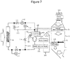
- Fig. 7 shows a schematic diagram of a fourth example of the configuration of the refrigeration cycle in the vehicle air conditioning apparatus according to the present embodiment.
- the fourth example of the configuration of the refrigeration cycle is an example in which the bypass passage 43 and the valve device 40 are applied to the apparatus described in Fig. 6 of International Publication WO 2013/035130 .
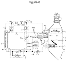
- Fig. 8 shows a schematic diagram of a fifth example of the configuration of the refrigeration cycle in the vehicle air conditioning apparatus according to the present embodiment.
- the fifth example of the configuration of the refrigeration cycle is an example in which the bypass passage 43 and the valve device 40 are applied to the apparatus described in Fig. 7 of International Publication WO 2013/035130 .
- the vehicle air conditioning apparatus it is preferable to further have the refrigerant temperature detection unit 50 which can detect the temperature of the liquid-phase refrigerant inside the accumulator, wherein the compressor 6 is of an electric type, and wherein the control device 23 starts the compressor 6 at the specified rotation speed, and sets the state in which the flow of refrigerant in the bypass passage 43 is allowed by the valve device 40 (sets the state shown in Fig.
- an estimated superheat degree T_est of the gas-phase refrigerant 48 inside the accumulator 10 which is obtained when the flow of refrigerant in the bypass passage 43 is blocked, from the specified rotation speed of the compressor 6 and from the temperature information obtained from the refrigerant temperature detection unit 50, compares the estimated superheat degree T_est and a predetermined threshold superheat degree T_def, and when the estimated superheat degree T_est falls below the threshold superheat degree T_def, causes the valve device 40 to block the flow of refrigerant in the bypass passage 43 (sets the state shown in Fig. 10 ). It is possible to estimate the time at which to close the valve device and thus possible to accurately suppress an occurrence of bumping.
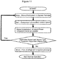
- Fig. 11 shows a specific control flowchart of the control device 23.
- the compressor 6 is of an electric type, it is possible to control the compressor 6 at the rotation speed specified by the control device 23. Then, it is possible, from the rotation speed of the compressor 6, to estimate the pressure (hereafter referred to as the estimated pressure) of the gas-phase refrigerant 48 in the accumulator 10 after blocking the flow of refrigerant in the bypass passage 43.
- the estimated superheat degree T_est is calculated from the estimated pressure and from the temperature information obtained from the refrigerant temperature detection unit 50.
- the formula to calculate a superheat degree is, as a premise, a formula to estimate that there occurs no bumping when the valve device 40 having been open is closed.
- the superheat degree is defined as the "estimated superheat degree T_est" when the valve device 40 is closed.
- the estimated superheat degree T_est is calculated as in the following formula (Math. 1).
- T_est 1 ⁇ ⁇ T_liq ⁇ ⁇ ⁇ V_eva ⁇ ⁇ ⁇ P_vs
- T_out an outside air load (an outside air temperature) T_out
- the higher an outside air load (an outside air temperature) T_out the smaller the amount of refrigerant accumulated in the accumulator, and the larger a gas-phase region, so that a decrement in the gas-phase pressure P_vs is gradual even though the refrigerant is sucked in by the compressor 6, and a rise in the gas-phase pressure P_vs is also gradual even in the event that the refrigerant evaporation amount V_eva is constant.
- the threshold superheat degree T_def is set to be lower by a predetermined temperature than the boiling temperature of the liquid refrigerant.
- the predetermined temperature is set to be, preferably, a prescribed temperature which is selected from a range of 1°C to 6°C, more preferably, a prescribed temperature which is selected from a range of 2°C to 5°C.
- the threshold superheat degree T_def is set to be, for example, preferably 2°C, more preferably 5°C, lower than the boiling temperature.
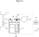
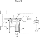
- Figs. 3 , 12 , and 13 will be referred to.
- This mode is an example in which the on/off valve of the mode shown in Figs. 2 , 9 , and 10 is changed to the three-way valve.
- Fig. 12 shows the state in which the flow of refrigerant in the bypass passage 43 is allowed by the valve device 40.
- Fig. 13 shows the state in which the flow of refrigerant in the bypass passage 43 is blocked by the valve device 40.
- the control in the control flowchart shown in Fig. 11 can also be applied to the mode shown in Figs. 3 , 12 , and 13 .
- the control device 23 sets the state in which the flow of refrigerant in the bypass passage 43 is allowed by the valve device 40 when the compressor 6 is started (sets the state shown in Fig. 9 ), and subsequently, sets the state in which the flow of refrigerant in the bypass passage 43 is blocked by the valve device 40 after a predetermined time has passed (sets the state shown in Fig. 10 ).
- the control device 23 includes a timer function.
- Fig. 14 shows a specific control flowchart of the control device 23.
- the predetermined time is a prescribed time which is selected from a range of, for example, 90 to 180 seconds.
- Fig. 4 a description will be given, referring to Fig. 4 , of the vehicle air conditioning apparatus according to the present embodiment.
- the vehicle air conditioning apparatus it is preferable to further have the vehicle exterior temperature detection unit 51, wherein the control device 23, when the compressor 6 is started, sets the state in which the flow of refrigerant in the bypass passage 43 is allowed by the valve device 40 when the vehicle exterior temperature obtained from the vehicle exterior temperature detection unit 51 is lower than the predetermined temperature, and sets the state in which the flow of refrigerant in the bypass passage 43 is blocked by the valve device 40 when the vehicle exterior temperature is equal to or higher than the predetermined temperature. It is possible, by using the vehicle exterior temperature detection unit 51, to accurately suppress an occurrence of bumping with the configuration remaining simple.
- Fig. 15 shows a specific control flowchart of the control device 23.
- the predetermined temperature of the vehicle exterior temperature is a prescribed temperature which is selected from a range of, for example, 5°C or lower.
- the vehicle air conditioning apparatus can, in any mode, avoid an excessively depressurized state of the internal space in the accumulator 10. It is thereby possible to suppress an occurrence of bumping of the liquid-phase refrigerant, and therefore possible to suppress an abnormal noise occurring in the accumulator due to the bumping phenomenon.
Landscapes
- Engineering & Computer Science (AREA)
- Physics & Mathematics (AREA)
- Mechanical Engineering (AREA)
- Thermal Sciences (AREA)
- General Engineering & Computer Science (AREA)
- Chemical & Material Sciences (AREA)
- Analytical Chemistry (AREA)
- Power Engineering (AREA)
- Air-Conditioning For Vehicles (AREA)
Abstract
Description
- The present disclosure relates to a vehicle air conditioning apparatus including a refrigeration cycle having an accumulator.
- In a refrigeration cycle having an accumulator on the upstream side of a compressor, there is a case in which a refrigerant boils inside the accumulator immediately after the compressor is started, causing an abnormal noise to occur. Therefore, a technology which aims to suppress the noise occurring and the refrigerant boiling down is provided (for example, refer to Patent Literature 1).
-
Patent Literature 1 aims to suppress the refrigerant coming to a boil by driving a stirring device utilizing the flow of refrigerant flowing into the accumulator and thus stirring a liquid-phase refrigerant accumulated inside the accumulator. - Also, an idea is disclosed wherein a vent is provided in an upper portion of a refrigerant outflow pipe inside the accumulator, short-circuiting a gas-phase refrigerant inside the accumulator (for example, refer to Patent Literature 2) .
- Patent Literature 1:
JP-A-2017-058070 - Patent Literature 2:
JP-A-2000-088402 - In the technology of
Patent Literature 1, however, there is a disadvantage in that a stirring device 90 is installed, thus leading to a complexity in the internal structure of the accumulator. - Also, in the technology of
Patent Literature 2, it is necessary, from a liquid-phase refrigerant accumulated in a lower portion inside the accumulator, to suck out a lubricant dissolved therein, and it is essential for the refrigerant outflow pipe extending to the lower portion inside the accumulator to exert a certain suction power at the lower side leading end, so that a vent such as shown bysign 17 inPatent Literature 2 cannot be set to be indiscriminately large in size. - In the meantime, it is because the internal space of the accumulator is sharply reduced in pressure that the liquid-phase refrigerant boils immediately after the compressor is started. It is considered to take countermeasures thereagainst, for example, by restricting the rotation speed (keeping the rotation speed low) immediately after the compressor is started and thus preventing excessive refrigerant from being sucked in, but by so doing, there is a problem in that it is not possible to obtain an adequate rapid cooling or heating capacity required for the refrigeration cycle.
- Therefore, the present disclosure has for its object to provide a vehicle air conditioning apparatus having a refrigeration cycle, which, while fully performing a desired temperature control function required for the vehicle air conditioning apparatus, can avoid an excessively depressurized state inside an accumulator.
- The present inventors, after their earnest studies, have found out that an abnormal noise due to bumping can be suppressed by providing a bypass passage which connects outside the accumulator a refrigerant inlet pipe, which causes a refrigerant circulating through a refrigeration cycle to flow into an accumulator, and a refrigerant outlet pipe, which causes the refrigerant to flow out from the accumulator, thus short-circuiting the refrigerant, enabling the refrigerant to circulate, and has completed the present invention. That is, the vehicle air conditioning apparatus according to the present invention includes a refrigeration cycle which includes at least a compressor, an outdoor heat exchanger, an expanding device, an evaporator, and an accumulator and in which these elements are connected in this order by piping; a bypass passage which connects outside the accumulator a refrigerant inlet pipe, which causes a refrigerant circulating through the refrigeration cycle to flow into the accumulator, and a refrigerant outlet pipe, which causes the refrigerant to flow out from the accumulator, thus short-circuiting the refrigerant, enabling the refrigerant to circulate; a valve device which, being provided in the bypass passage, has an opening/closing function; and a control device which controls at least the compressor and the valve device.
- In the vehicle air conditioning apparatus according to the present invention, it is preferable that the valve device is an on/off valve which allows or blocks the flow of the refrigerant in the bypass passage. The flow of the refrigerant in the bypass passage can be controlled with a simple structure.
- In the vehicle air conditioning apparatus according to the present invention, it is preferable that the valve device is a three-way valve which is disposed at the confluence of the bypass passage and the refrigerant outlet pipe. The flow of the refrigerant in the bypass passage can be controlled with a simple structure.
- In the vehicle air conditioning apparatus according to the present invention, it is preferable to further include a refrigerant temperature detection unit which can detect the temperature of a liquid-phase refrigerant inside the accumulator, wherein the compressor is of an electric type, and wherein the control device starts the compressor at a specified rotation speed and sets the state in which the flow of the refrigerant in the bypass passage is allowed by the valve device, subsequently, calculates an estimated superheat degree T_est of a gas-phase refrigerant inside the accumulator, which is obtained when the flow of the refrigerant in the bypass passage is blocked, from the specified rotation speed of the compressor and from temperature information obtained from the refrigerant temperature detection unit, compares the estimated superheat degree T_est and a predetermined threshold superheat degree T_def, and when the estimated superheat degree T_est falls below the threshold superheat degree T_def, causes the valve device to block the flow of the refrigerant in the bypass passage. It is possible to estimate the time at which to close the valve device and thus possible to accurately suppress an occurrence of bumping.
- In the vehicle air conditioning apparatus according to the present invention, it is preferable that a temperature sensor portion of the refrigerant temperature detection unit is disposed on the lower side of the center in the internal space of the accumulator or on the outer bottom surface of the accumulator. It is possible to more accurately estimate the time at which to close the valve device, and as a result, it is possible to more accurately suppress an occurrence of bumping.
- In the vehicle air conditioning apparatus according to the present invention, it is preferable that the control device, when the compressor is started, sets the state in which the flow of the refrigerant in the bypass passage is allowed by the valve device, and subsequently, after a predetermined time has passed, sets the state in which the flow of the refrigerant in the bypass passage is blocked by the valve device. It is possible, even without providing the refrigerant temperature detection unit, to accurately suppress an occurrence of bumping with the configuration remaining simple.
- In the vehicle air conditioning apparatus according to the present invention, it is preferable to further include a vehicle exterior temperature detection unit, wherein the control device, when the compressor is started, sets the state in which the flow of the refrigerant in the bypass passage is allowed by the valve device when a vehicle exterior temperature obtained from the vehicle exterior temperature detection unit is lower than a predetermined temperature, and sets the state in which the flow of the refrigerant in the bypass passage is blocked by the valve device when the vehicle exterior temperature is equal to or higher than the predetermined temperature. It is possible, by using the vehicle exterior temperature detection unit, to accurately suppress an occurrence of bumping with the configuration remaining simple.
- According to the present disclosure, it is possible to provide the vehicle air conditioning apparatus having the refrigeration cycle, which, while fully performing the desired temperature control function required for the vehicle air conditioning apparatus, can avoid the excessively depressurized state inside the accumulator.
-
-
Fig. 1 is a schematic diagram showing a first example of the configuration of a cooling refrigeration cycle in a vehicle air conditioning apparatus according to the present embodiment. -
Fig. 2 is a schematic diagram showing a first example of an accumulator including a bypass passage. -
Fig. 3 is a schematic diagram showing a second example of the accumulator including the bypass passage. -
Fig. 4 is a schematic diagram showing a third example of the accumulator including the bypass passage. -
Figs. 5A and 5B are schematic diagrams showing a second example of the configuration of the refrigeration cycle in the vehicle air conditioning apparatus according to the present embodiment. -
Figs. 6A and 6B are schematic diagrams showing a third example of the configuration of the refrigeration cycle in the vehicle air conditioning apparatus according to the present embodiment. -
Fig. 7 is a schematic diagram showing a fourth example of the configuration of the refrigeration cycle in the vehicle air conditioning apparatus according to the present embodiment. -
Fig. 8 is a schematic diagram showing a fifth example of the configuration of the refrigeration cycle in the vehicle air conditioning apparatus according to the present embodiment. -
Fig. 9 is a schematic diagram showing the state in which the flow of refrigerant in the bypass passage is "allowed" in the accumulator of the first example. -
Fig. 10 is a schematic diagram showing the state in which the flow of refrigerant in the bypass passage is "blocked" in the accumulator of the first example. -
Fig. 11 is a flowchart showing a first example of controlling the flow of refrigerant in the bypass passage when a compressor is started. -
Fig. 12 is a schematic diagram showing the state in which the flow of refrigerant in the bypass passage is "allowed" in the accumulator of the second example. -
Fig. 13 is a schematic diagram showing the state in which the flow of refrigerant in the bypass passage is "blocked" in the accumulator of the second example. -
Fig. 14 is a flowchart showing a second example of controlling the flow of refrigerant in the bypass passage when the compressor is started. -
Fig. 15 is a flowchart showing a third example of controlling the flow of refrigerant in the bypass passage when the compressor is started. - Hereafter, a description will be given, referring to the accompanying drawings, of one aspect of the present invention. An embodiment to be described hereafter is a working example of the present invention, and the present invention is not limited to the following embodiment. In the present description and drawings, component elements with the same signs shall indicate mutually identical ones. The embodiment may be modified in various ways as long as the modifications exert advantageous effects of the present invention.
- A description will be given, referring to
Figs. 1 and2 , of a vehicle air conditioning apparatus according to the present embodiment. The vehicle air conditioning apparatus according to the present embodiment includes arefrigeration cycle 80, which includes at least acompressor 6, anoutdoor heat exchanger 4, an expandingdevice 12, anevaporator 3, and anaccumulator 10 and in which these elements are connected in this order by piping, abypass passage 43, which connects outside theaccumulator 10 arefrigerant inlet pipe 41, which causes a refrigerant circulating through therefrigeration cycle 80 to flow into theaccumulator 10, and arefrigerant outlet pipe 42, which causes the refrigerant to flow out from theaccumulator 10, thus short-circuiting the refrigerant, enabling the refrigerant to circulate, avalve device 40 which, being provided in thebypass passage 43, has an opening/closing function, and acontrol device 23 which controls at least thecompressor 6 and thevalve device 40. - The basic configuration of the refrigeration cycle for cooling includes the
compressor 6, theoutdoor heat exchanger 4, the expandingdevice 12, theevaporator 3, and theaccumulator 10, as shown inFig. 1 . Thecompressor 6 sucks in and compresses the refrigerant. Thecompressor 6 is rotary driven by a not-shown vehicle driving engine via apulley 63, a belt, and the like. As thecompressor 6, either a variable capacity compressor or a fixed capacity compressor may be used. Also, in the event of using an electric compressor as thecompressor 6, the capability to discharge the refrigerant can be adjusted by adjusting the rotation speed of an electric motor. Also, the use of the electric compressor can obviate the necessity of the connection with the vehicle driving engine via the belt and the like. A high-pressure gas-phase refrigerant discharged from thecompressor 6 flows into theoutdoor heat exchanger 4 and herein is heat exchanged with outside air, cooled, and condensed. A liquid refrigerant condensed in theoutdoor heat exchanger 4 is next reduced in pressure to a low pressure in the expandingdevice 12, turning into a misty, gas-liquid two-phase state. The expandingdevice 12 is formed of a fixed aperture, such as an orifice or a nozzle, or an appropriate variable aperture. The low-pressure refrigerant reduced in pressure, in theevaporator 3, absorbs heat from the air blown by a not-shown air conditioning blower and evaporates. Theevaporator 3 is disposed in a not-shown air-conditioner casing, and cold air cooled in theevaporator 3, after being adjusted in temperature by a not-shown heater core section, is blown out into a vehicle interior. The refrigerant having passed through theevaporator 3, after being gas-liquid separated in theaccumulator 10, is sucked into thecompressor 6. Theaccumulator 10 plays the role of separating the refrigerant having flowed out from theevaporator 3 into a gas-phase refrigerant and a liquid-phase refrigerant, storing the liquid-phase refrigerant, and causing the gas-phase refrigerant to be sucked into thecompressor 6. Theaccumulator 10 also plays the role of causing oil, which is dissolved in the liquid refrigerant accumulating in a tank bottom portion, to be sucked into thecompressor 6. - A refrigerant 44 shown in
Fig. 2 is a refrigerant which has flowed out from theevaporator 3 and is in the gas-liquid two-phase state. The refrigerant 44 having passed through therefrigerant inlet pipe 41 connected to theevaporator 3 flows into the internal space of atank 45 through aninflow opening 46 provided in thetank 45. An accumulated liquid-phase refrigerant 47 and a gas-phase refrigerant 48 exist in the internal space of thetank 45. The refrigerant 44 in the gas-liquid two-phase state is separated by a gas-liquid separator 52 into the gas-phase refrigerant and the liquid-phase refrigerant. The gas-phase refrigerant 48 is sent to thecompressor 6 through therefrigerant outlet pipe 42 connected to anoutflow opening 49 provided in thetank 45. - The
bypass passage 43 connects outside theaccumulator 10 therefrigerant inlet pipe 41 and therefrigerant outlet pipe 42 which causes the refrigerant to flow out from theaccumulator 10, thus short-circuiting the refrigerant, enabling the refrigerant to circulate. Thevalve device 40 for carrying out the opening/closing of thebypass passage 43 is provided in thebypass passage 43. The flow of refrigerant in thebypass passage 43 is "allowed" or "blocked" by thevalve device 40. It is preferable here that thevalve device 40 is an on/off valve such as shown inFig. 2 . The on/off valve can control the flow of refrigerant in thebypass passage 43 with a simple structure. That is, when the on/off valve is opened, the flow of refrigerant in the bypass passage is "allowed". As therefrigerant inlet pipe 41 and therefrigerant outlet pipe 42 are not closed at this time, the refrigerant can flow into theaccumulator 10, but airflow resistance is lower when the refrigerant flows in thebypass passage 43 than when the refrigerant flows in theaccumulator 10, so that the refrigerant flows dominantly in thebypass passage 43. At this time, the pressure in thebypass passage 43 and the pressure in theaccumulator 10 are spontaneously approximated to each other. On the other hand, when the on/off valve is closed, the flow of refrigerant in the bypass passage is "blocked", and the refrigerant flows into theaccumulator 10. - It is preferable, as shown in
Fig. 3 , that thevalve device 40 is a three-way valve which is disposed at the confluence of thebypass passage 43 and therefrigerant outlet pipe 42. The three-way valve can control the flow of refrigerant in thebypass passage 43 with a simple structure. That is, when the three-way valve opens the bypass passage and closes therefrigerant outlet pipe 42, the flow of refrigerant in the bypass passage is "allowed". At this time, therefrigerant outlet pipe 42 is closed, and so the refrigerant does not flow into theaccumulator 10. However, as therefrigerant inlet pipe 41 is not closed, the pressure in thebypass passage 43 and the pressure in theaccumulator 10 are spontaneously approximated to each other. On the other hand, when the three-way valve closes the bypass passage and opens therefrigerant outlet pipe 42, the flow of refrigerant in the bypass passage is "blocked", and the refrigerant flows into theaccumulator 10. - The
valve device 40, whether it is the on/off valve shown inFig. 2 or the three-way valve shown inFig. 3 , acts equally in both "allowing" and "blocking" the flow of refrigerant in thebypass passage 43, as heretofore described. - In the vehicle air conditioning apparatus according to the present embodiment, it is preferable, as shown in
Fig. 2 , that it further has a refrigeranttemperature detection unit 50 which can detect the temperature of the liquid-phase refrigerant 47 inside theaccumulator 10. It is preferable here that a temperature sensor portion of the refrigeranttemperature detection unit 50 is disposed on the lower side of the center in the internal space of theaccumulator 10 or on the outer bottom surface of theaccumulator 10. The temperature sensor portion is disposed in such a place, and thereby the temperature of the liquid-phase refrigerant 47 can be accurately detected.Fig. 2 shows the mode in which the temperature sensor portion of the refrigeranttemperature detection unit 50 is disposed on the outer bottom surface of theaccumulator 10. It is possible to more accurately estimate the time at which to close the valve device, and as a result, it is possible to more accurately suppress an occurrence of bumping. Also, the temperature sensor portion of the refrigeranttemperature detection unit 50, when being disposed on the lower side of the center in the internal space of theaccumulator 10, can accurately measure the liquid temperature of the liquid-phase refrigerant 47 even in the event that the amount of liquid-phase refrigerant 47 accumulated in theaccumulator 10, which can fluctuate, fluctuates. - In the vehicle air conditioning apparatus according to the present embodiment, it is preferable, as shown in
Fig. 4 , to further have a vehicle exteriortemperature detection unit 51. In the modes shown inFigs. 2 and3 , too, it is preferable to further have the vehicle exteriortemperature detection unit 51. The refrigerant boils inside theaccumulator 10 immediately after thecompressor 6 is started, and although depending also on what the rotation speed of the compressor is, an abnormal noise is generally more apt to occur under the condition that the vehicle exterior temperature is moderate (for example, 20°C) or lower (for example, 10°C) than under the condition that it is relatively high (for example, 35°C), so that the timing with which to operate opening/closing of thevalve device 40 can be accurately adjusted by comprehending the vehicle exterior temperature. - The
control device 23 controls whether thevalve device 40 is to "allow" or "block" the flow of refrigerant in thebypass passage 43. For example, thecontrol device 23 controls switching between opening and closing the on/off valve. Also, thecontrol device 23 controls the switching of the three-way valve between both opening thebypass passage 43 and closing therefrigerant outlet pipe 42 and both closing thebypass passage 43 and opening therefrigerant outlet pipe 42. Furthermore, thecontrol device 23 carries out the control of the operation of thecompressor 6. For example, when thecompressor 6 is an electric compressor, thecontrol device 23 specifies the rotation speed of the electric compressor, and the electric compressor is driven so as to achieve the specified rotation speed. Also, thecontrol device 23, in addition to carrying out the control of thevalve device 40 and thecompressor 6, may carry out the control of another device. Furthermore, thecontrol device 23 may obtain information from each kind of sensor, for example, may obtain information on the temperature of the liquid-phase refrigerant inside the accumulator from the refrigeranttemperature detection unit 50. Furthermore, thecontrol device 23 may obtain information on the vehicle exterior temperature from the vehicle exteriortemperature detection unit 51. - In the vehicle air conditioning apparatus according to the present embodiment, the
bypass passage 43 and thevalve device 40 may be applied not only to a simple cooling refrigeration cycle (a first example of the refrigeration cycle), but to a refrigeration cycle which enables dehumidification heating. Thebypass passage 43 and thevalve device 40 may be applied, for example, to a vehicle air conditioning apparatus disclosed in International PublicationWO 2013/035130 . Specifically, thebypass passage 43 and thevalve device 40 can be applied to the apparatus described inFig. 1 ,5 ,6 , or7 of the same publication. -
Figs. 5A and 5B show schematic diagrams of a second example of the configuration of the refrigeration cycle in the vehicle air conditioning apparatus according to the present embodiment. The second example of the configuration of the refrigeration cycle is an example in which thebypass passage 43 and thevalve device 40 are applied to the apparatus described inFig. 1 of International PublicationWO 2013/035130 . An on/offvalve 17 in the drawing of the same publication is common to the on/offvalve 17 in the drawings of the present application. -
Figs. 6A and 6B show schematic diagrams of a third example of the configuration of the refrigeration cycle in the vehicle air conditioning apparatus according to the present embodiment. The third example of the configuration of the refrigeration cycle is an example in which thebypass passage 43 and thevalve device 40 are applied to the apparatus described inFig. 5 of International PublicationWO 2013/035130 . -
Fig. 7 shows a schematic diagram of a fourth example of the configuration of the refrigeration cycle in the vehicle air conditioning apparatus according to the present embodiment. The fourth example of the configuration of the refrigeration cycle is an example in which thebypass passage 43 and thevalve device 40 are applied to the apparatus described inFig. 6 of International PublicationWO 2013/035130 . -
Fig. 8 shows a schematic diagram of a fifth example of the configuration of the refrigeration cycle in the vehicle air conditioning apparatus according to the present embodiment. The fifth example of the configuration of the refrigeration cycle is an example in which thebypass passage 43 and thevalve device 40 are applied to the apparatus described inFig. 7 of International PublicationWO 2013/035130 . - Next, a more detailed description will be given, referring to
Figs. 2 ,9 , and10 , of the vehicle air conditioning apparatus according to the present embodiment. In the vehicle air conditioning apparatus according to the present embodiment, it is preferable to further have the refrigeranttemperature detection unit 50 which can detect the temperature of the liquid-phase refrigerant inside the accumulator, wherein thecompressor 6 is of an electric type, and wherein thecontrol device 23 starts thecompressor 6 at the specified rotation speed, and sets the state in which the flow of refrigerant in thebypass passage 43 is allowed by the valve device 40 (sets the state shown inFig. 9 ), subsequently, calculates an estimated superheat degree T_est of the gas-phase refrigerant 48 inside theaccumulator 10, which is obtained when the flow of refrigerant in thebypass passage 43 is blocked, from the specified rotation speed of thecompressor 6 and from the temperature information obtained from the refrigeranttemperature detection unit 50, compares the estimated superheat degree T_est and a predetermined threshold superheat degree T_def, and when the estimated superheat degree T_est falls below the threshold superheat degree T_def, causes thevalve device 40 to block the flow of refrigerant in the bypass passage 43 (sets the state shown inFig. 10 ). It is possible to estimate the time at which to close the valve device and thus possible to accurately suppress an occurrence of bumping. The specific details are as follows.Fig. 11 shows a specific control flowchart of thecontrol device 23. As thecompressor 6 is of an electric type, it is possible to control thecompressor 6 at the rotation speed specified by thecontrol device 23. Then, it is possible, from the rotation speed of thecompressor 6, to estimate the pressure (hereafter referred to as the estimated pressure) of the gas-phase refrigerant 48 in theaccumulator 10 after blocking the flow of refrigerant in thebypass passage 43. The estimated superheat degree T_est is calculated from the estimated pressure and from the temperature information obtained from the refrigeranttemperature detection unit 50. Here, the formula to calculate a superheat degree is, as a premise, a formula to estimate that there occurs no bumping when thevalve device 40 having been open is closed. The superheat degree is defined as the "estimated superheat degree T_est" when thevalve device 40 is closed. The more a refrigerant intake Vs of thecompressor 6, the lower a gas-phase pressure P_vs of the internal space of theaccumulator 10 when thevalve device 40 is closed. Also, the higher a temperature T_liq of the liquid refrigerant, the higher a boiling point temperature, while the larger also a refrigerant evaporation amount V_eva of the liquid refrigerant, and so it is not necessarily true that the higher the temperature of the liquid refrigerant is, the more easily the liquid refrigerant boils. Taking these into account, the estimated superheat degree T_est is calculated as in the following formula (Math. 1). Here, α, β, and γ are each a coefficient.
compressor 6, and a rise in the gas-phase pressure P_vs is also gradual even in the event that the refrigerant evaporation amount V_eva is constant. Because of this, the estimated superheat degree T_est can be calculated with higher accuracy by reflecting the outside air temperature T_out in Math. 1. Specifically, the estimated superheat degree T_est is calculated as in the following formula (Math. 2).
valve device 40 is carried out. It is preferable to set the threshold superheat degree T_def to be lower by a predetermined temperature than the boiling temperature of the liquid refrigerant. The lower the threshold superheat degree T_def is set to be than the boiling temperature, the higher an anti-bumping effect is. Here, the predetermined temperature is set to be, preferably, a prescribed temperature which is selected from a range of 1°C to 6°C, more preferably, a prescribed temperature which is selected from a range of 2°C to 5°C. The threshold superheat degree T_def is set to be, for example, preferably 2°C, more preferably 5°C, lower than the boiling temperature. - Next,
Figs. 3 ,12 , and13 will be referred to. This mode is an example in which the on/off valve of the mode shown inFigs. 2 ,9 , and10 is changed to the three-way valve.Fig. 12 shows the state in which the flow of refrigerant in thebypass passage 43 is allowed by thevalve device 40.Fig. 13 shows the state in which the flow of refrigerant in thebypass passage 43 is blocked by thevalve device 40. The control in the control flowchart shown inFig. 11 can also be applied to the mode shown inFigs. 3 ,12 , and13 . - Next, a description will be given, referring to
Figs. 2 ,9 , and10 , of an example in which another control is carried out in the vehicle air conditioning apparatus according to the present embodiment. In the vehicle air conditioning apparatus according to the present embodiment, it is preferable that thecontrol device 23 sets the state in which the flow of refrigerant in thebypass passage 43 is allowed by thevalve device 40 when thecompressor 6 is started (sets the state shown inFig. 9 ), and subsequently, sets the state in which the flow of refrigerant in thebypass passage 43 is blocked by thevalve device 40 after a predetermined time has passed (sets the state shown inFig. 10 ). Thecontrol device 23 includes a timer function. It is possible, even without providing the refrigerant temperature detection unit, to accurately suppress an occurrence of bumping with the configuration remaining simple.Fig. 14 shows a specific control flowchart of thecontrol device 23. The predetermined time is a prescribed time which is selected from a range of, for example, 90 to 180 seconds. - Next, a description will be given, referring to
Fig. 4 , of the vehicle air conditioning apparatus according to the present embodiment. In the vehicle air conditioning apparatus according to the present embodiment, it is preferable to further have the vehicle exteriortemperature detection unit 51, wherein thecontrol device 23, when thecompressor 6 is started, sets the state in which the flow of refrigerant in thebypass passage 43 is allowed by thevalve device 40 when the vehicle exterior temperature obtained from the vehicle exteriortemperature detection unit 51 is lower than the predetermined temperature, and sets the state in which the flow of refrigerant in thebypass passage 43 is blocked by thevalve device 40 when the vehicle exterior temperature is equal to or higher than the predetermined temperature. It is possible, by using the vehicle exteriortemperature detection unit 51, to accurately suppress an occurrence of bumping with the configuration remaining simple.Fig. 15 shows a specific control flowchart of thecontrol device 23. The predetermined temperature of the vehicle exterior temperature is a prescribed temperature which is selected from a range of, for example, 5°C or lower. - The vehicle air conditioning apparatus according to the present embodiment can, in any mode, avoid an excessively depressurized state of the internal space in the
accumulator 10. It is thereby possible to suppress an occurrence of bumping of the liquid-phase refrigerant, and therefore possible to suppress an abnormal noise occurring in the accumulator due to the bumping phenomenon. -
- 3:
- evaporator
- 4:
- outdoor heat exchanger
- 6:
- compressor
- 10:
- accumulator
- 12:
- expanding device
- 17:
- on/off valve
- 23:
- control device
- 40:
- valve device
- 41:
- refrigerant inlet pipe
- 42:
- refrigerant outlet pipe
- 43:
- bypass passage
- 44:
- refrigerant
- 45:
- tank
- 46:
- inflow opening
- 47:
- liquid-phase refrigerant
- 48:
- gas-phase refrigerant
- 49:
- outflow opening
- 50:
- refrigerant temperature detection unit
- 51:
- vehicle exterior temperature detection unit
- 52:
- gas-liquid separator
- 63:
- pulley
- 80:
- refrigeration cycle
Claims (7)
- A vehicle air conditioning apparatus, comprising:a refrigeration cycle (80) which includes at least a compressor (6), an outdoor heat exchanger (4), an expanding device (12), an evaporator (3), and an accumulator (10) and in which these elements are connected in this order by piping;a bypass passage (43) which connects outside the accumulator a refrigerant inlet pipe (41), which causes a refrigerant circulating through the refrigeration cycle to flow into the accumulator, and a refrigerant outlet pipe (42), which causes the refrigerant to flow out from the accumulator, thus short-circuiting the refrigerant, enabling the refrigerant to circulate;a valve device (40) which, being provided in the bypass passage, has an opening/closing function; anda control device (23) which controls at least the compressor and the valve device.
- The vehicle air conditioning apparatus according to claim 1, wherein
the valve device is an on/off valve which allows or blocks the flow of the refrigerant in the bypass passage. - The vehicle air conditioning apparatus according to claim 1, wherein
the valve device is a three-way valve which is disposed at the confluence of the bypass passage and the refrigerant outlet pipe. - The vehicle air conditioning apparatus according to any one of claims 1 to 3, further comprising:a refrigerant temperature detection unit (50) which can detect the temperature of a liquid-phase refrigerant inside the accumulator, whereinthe compressor is of an electric type, and whereinthe control device starts the compressor at a specified rotation speed and sets the state in which the flow of the refrigerant in the bypass passage is allowed by the valve device, subsequently,calculates an estimated superheat degree T_est of a gas-phase refrigerant (48) inside the accumulator, which is obtained when the flow of the refrigerant in the bypass passage is blocked, from the specified rotation speed of the compressor and from temperature information obtained from the refrigerant temperature detection unit,compares the estimated superheat degree T_est and a predetermined threshold superheat degree T_def, and when the estimated superheat degree T_est falls below the threshold superheat degree T_def, causes the valve device to block the flow of the refrigerant in the bypass passage.
- The vehicle air conditioning apparatus according to claim 4, wherein
a temperature sensor portion of the refrigerant temperature detection unit is disposed on the lower side of the center in the internal space of the accumulator or on the outer bottom surface of the accumulator. - The vehicle air conditioning apparatus according to any one of claims 1 to 3, wherein
the control device, when the compressor is started, sets the state in which the flow of the refrigerant in the bypass passage is allowed by the valve device, and subsequently, after a predetermined time has passed, sets the state in which the flow of the refrigerant in the bypass passage is blocked by the valve device. - The vehicle air conditioning apparatus according to any one of claims 1 to 3, further comprising:a vehicle exterior temperature detection unit (51), whereinthe control device, when the compressor is started, sets the state in which the flow of the refrigerant in the bypass passage is allowed by the valve device when a vehicle exterior temperature obtained from the vehicle exterior temperature detection unit is lower than a predetermined temperature, and sets the state in which the flow of the refrigerant in the bypass passage is blocked by the valve device when the vehicle exterior temperature is equal to or higher than the predetermined temperature.
Applications Claiming Priority (1)
| Application Number | Priority Date | Filing Date | Title |
|---|---|---|---|
| JP2018243127A JP2020104591A (en) | 2018-12-26 | 2018-12-26 | Vehicular air conditioner |
Publications (1)
| Publication Number | Publication Date |
|---|---|
| EP3674627A1 true EP3674627A1 (en) | 2020-07-01 |
Family
ID=69411068
Family Applications (1)
| Application Number | Title | Priority Date | Filing Date |
|---|---|---|---|
| EP19218445.5A Withdrawn EP3674627A1 (en) | 2018-12-26 | 2019-12-20 | Vehicle air conditioning apparatus |
Country Status (2)
| Country | Link |
|---|---|
| EP (1) | EP3674627A1 (en) |
| JP (1) | JP2020104591A (en) |
Cited By (3)
| Publication number | Priority date | Publication date | Assignee | Title |
|---|---|---|---|---|
| CN114877574A (en) * | 2022-06-07 | 2022-08-09 | 浙江欧特立汽车空调有限公司 | Liquid storage device for new energy automobile air conditioning system and working method of liquid storage device |
| US20250196569A1 (en) * | 2023-12-14 | 2025-06-19 | Rivian Ip Holdings, Llc | Bypass for heat pump systems |
| US12522053B2 (en) | 2020-12-02 | 2026-01-13 | Valeo Systemes Thermiques | Refrigerating fluid circuit comprising an accumulator bypass branch |
Families Citing this family (1)
| Publication number | Priority date | Publication date | Assignee | Title |
|---|---|---|---|---|
| WO2024053334A1 (en) * | 2022-09-07 | 2024-03-14 | 株式会社デンソー | Refrigeration cycle device |
Citations (6)
| Publication number | Priority date | Publication date | Assignee | Title |
|---|---|---|---|---|
| JP2000088402A (en) | 1998-07-13 | 2000-03-31 | Showa Alum Corp | Accumulator |
| DE102004049612A1 (en) * | 2003-10-14 | 2005-05-25 | Denso Corp., Kariya | Refrigerating cycle apparatus for indoor heat exchanger of vehicle air conditioner, has external bypass route which is connected to accumulator and performs substantial bypass of vapor liquid separation space |
| WO2013035130A1 (en) | 2011-09-06 | 2013-03-14 | 株式会社ヴァレオジャパン | Vehicle air-conditioning apparatus |
| EP3088819A1 (en) * | 2015-01-23 | 2016-11-02 | Mitsubishi Electric Corporation | Air conditioning device |
| JP2017058070A (en) | 2015-09-16 | 2017-03-23 | 本田技研工業株式会社 | Air conditioner |
| CN108180679A (en) * | 2017-12-27 | 2018-06-19 | 青岛海信日立空调系统有限公司 | The control method of refrigeration system, air conditioner and air conditioner |
-
2018
- 2018-12-26 JP JP2018243127A patent/JP2020104591A/en active Pending
-
2019
- 2019-12-20 EP EP19218445.5A patent/EP3674627A1/en not_active Withdrawn
Patent Citations (6)
| Publication number | Priority date | Publication date | Assignee | Title |
|---|---|---|---|---|
| JP2000088402A (en) | 1998-07-13 | 2000-03-31 | Showa Alum Corp | Accumulator |
| DE102004049612A1 (en) * | 2003-10-14 | 2005-05-25 | Denso Corp., Kariya | Refrigerating cycle apparatus for indoor heat exchanger of vehicle air conditioner, has external bypass route which is connected to accumulator and performs substantial bypass of vapor liquid separation space |
| WO2013035130A1 (en) | 2011-09-06 | 2013-03-14 | 株式会社ヴァレオジャパン | Vehicle air-conditioning apparatus |
| EP3088819A1 (en) * | 2015-01-23 | 2016-11-02 | Mitsubishi Electric Corporation | Air conditioning device |
| JP2017058070A (en) | 2015-09-16 | 2017-03-23 | 本田技研工業株式会社 | Air conditioner |
| CN108180679A (en) * | 2017-12-27 | 2018-06-19 | 青岛海信日立空调系统有限公司 | The control method of refrigeration system, air conditioner and air conditioner |
Cited By (5)
| Publication number | Priority date | Publication date | Assignee | Title |
|---|---|---|---|---|
| US12522053B2 (en) | 2020-12-02 | 2026-01-13 | Valeo Systemes Thermiques | Refrigerating fluid circuit comprising an accumulator bypass branch |
| CN114877574A (en) * | 2022-06-07 | 2022-08-09 | 浙江欧特立汽车空调有限公司 | Liquid storage device for new energy automobile air conditioning system and working method of liquid storage device |
| CN114877574B (en) * | 2022-06-07 | 2022-10-14 | 浙江欧特立汽车空调有限公司 | Liquid storage device for new energy automobile air conditioning system and working method of liquid storage device |
| US20250196569A1 (en) * | 2023-12-14 | 2025-06-19 | Rivian Ip Holdings, Llc | Bypass for heat pump systems |
| US12420611B2 (en) * | 2023-12-14 | 2025-09-23 | Rivian Ip Holdings, Llc | Bypass for heat pump systems |
Also Published As
| Publication number | Publication date |
|---|---|
| JP2020104591A (en) | 2020-07-09 |
Similar Documents
| Publication | Publication Date | Title |
|---|---|---|
| US11787258B2 (en) | Refrigeration cycle device | |
| EP2136158B1 (en) | Refrigerating device | |
| US8539785B2 (en) | Condensing unit having fluid injection | |
| US8925337B2 (en) | Air conditioning systems and methods having free-cooling pump-protection sequences | |
| US20180022185A1 (en) | Heat pump cycle | |
| EP3023712A1 (en) | A method for controlling a vapour compression system with a receiver | |
| US20140007601A1 (en) | Outdoor unit for air-conditioning apparatus, and air-conditioning apparatus | |
| WO2018110185A1 (en) | Refrigerant circuit system and method for controlling refrigerant circuit system | |
| US8117859B2 (en) | Methods and systems for controlling air conditioning systems having a cooling mode and a free-cooling mode | |
| US20040084175A1 (en) | Multi-zone temperature control system | |
| US20100036530A1 (en) | Air conditioning systems and methods having free-cooling pump starting sequences | |
| JP2018095182A (en) | Refrigeration cycle equipment | |
| CN112400088A (en) | Refrigeration device and associated operating method | |
| JP2020104591A (en) | Vehicular air conditioner | |
| EP3601907B1 (en) | A vapour compression system with a suction line liquid separator | |
| JPH09318166A (en) | Refrigerating apparatus | |
| JP6758485B2 (en) | Refrigeration cycle equipment | |
| EP1489369A1 (en) | Unit for calculating refrigerant suction pressure of compressor in refrigeration cycle | |
| JP5517891B2 (en) | Air conditioner | |
| JPH0674579A (en) | Refrigeration equipment | |
| EP3412482A1 (en) | Vehicle air conditioning device, vehicle provided with same, and method for controlling vehicle grill device | |
| EP3628940B1 (en) | A method for controlling a vapour compression system based on estimated flow | |
| JP3982557B2 (en) | Air conditioner | |
| KR20160096947A (en) | An air conditioning system and a method for controlling the same | |
| JP4183538B2 (en) | Operation control device for condenser fan |
Legal Events
| Date | Code | Title | Description |
|---|---|---|---|
| PUAI | Public reference made under article 153(3) epc to a published international application that has entered the european phase |
Free format text: ORIGINAL CODE: 0009012 |
|
| STAA | Information on the status of an ep patent application or granted ep patent |
Free format text: STATUS: THE APPLICATION HAS BEEN PUBLISHED |
|
| AK | Designated contracting states |
Kind code of ref document: A1 Designated state(s): AL AT BE BG CH CY CZ DE DK EE ES FI FR GB GR HR HU IE IS IT LI LT LU LV MC MK MT NL NO PL PT RO RS SE SI SK SM TR |
|
| AX | Request for extension of the european patent |
Extension state: BA ME |
|
| STAA | Information on the status of an ep patent application or granted ep patent |
Free format text: STATUS: REQUEST FOR EXAMINATION WAS MADE |
|
| 17P | Request for examination filed |
Effective date: 20201218 |
|
| RBV | Designated contracting states (corrected) |
Designated state(s): AL AT BE BG CH CY CZ DE DK EE ES FI FR GB GR HR HU IE IS IT LI LT LU LV MC MK MT NL NO PL PT RO RS SE SI SK SM TR |
|
| GRAP | Despatch of communication of intention to grant a patent |
Free format text: ORIGINAL CODE: EPIDOSNIGR1 |
|
| STAA | Information on the status of an ep patent application or granted ep patent |
Free format text: STATUS: GRANT OF PATENT IS INTENDED |
|
| RIC1 | Information provided on ipc code assigned before grant |
Ipc: F25B 5/02 20060101ALI20210301BHEP Ipc: F25B 6/04 20060101ALI20210301BHEP Ipc: F25B 43/00 20060101AFI20210301BHEP Ipc: F25B 49/02 20060101ALI20210301BHEP Ipc: F25B 6/02 20060101ALI20210301BHEP |
|
| INTG | Intention to grant announced |
Effective date: 20210319 |
|
| RIN1 | Information on inventor provided before grant (corrected) |
Inventor name: TSUJI, TERUAKI Inventor name: ONODERA, MUTSUHIRO Inventor name: ISHINO, HIROYUKI Inventor name: HIRASHITA, SHUNSUKE |
|
| STAA | Information on the status of an ep patent application or granted ep patent |
Free format text: STATUS: THE APPLICATION IS DEEMED TO BE WITHDRAWN |
|
| 18D | Application deemed to be withdrawn |
Effective date: 20210730 |