EP3674614B1 - Discharge air temperature reset for hvacr unit operating variable-air-volume box - Google Patents
Discharge air temperature reset for hvacr unit operating variable-air-volume box Download PDFInfo
- Publication number
- EP3674614B1 EP3674614B1 EP19217402.7A EP19217402A EP3674614B1 EP 3674614 B1 EP3674614 B1 EP 3674614B1 EP 19217402 A EP19217402 A EP 19217402A EP 3674614 B1 EP3674614 B1 EP 3674614B1
- Authority
- EP
- European Patent Office
- Prior art keywords
- setpoint temperature
- discharge air
- conditioned
- temperature
- hvacr
- Prior art date
- Legal status (The legal status is an assumption and is not a legal conclusion. Google has not performed a legal analysis and makes no representation as to the accuracy of the status listed.)
- Active
Links
Images


Classifications
-
- F—MECHANICAL ENGINEERING; LIGHTING; HEATING; WEAPONS; BLASTING
- F24—HEATING; RANGES; VENTILATING
- F24F—AIR-CONDITIONING; AIR-HUMIDIFICATION; VENTILATION; USE OF AIR CURRENTS FOR SCREENING
- F24F11/00—Control or safety arrangements
- F24F11/62—Control or safety arrangements characterised by the type of control or by internal processing, e.g. using fuzzy logic, adaptive control or estimation of values
- F24F11/63—Electronic processing
-
- F—MECHANICAL ENGINEERING; LIGHTING; HEATING; WEAPONS; BLASTING
- F24—HEATING; RANGES; VENTILATING
- F24F—AIR-CONDITIONING; AIR-HUMIDIFICATION; VENTILATION; USE OF AIR CURRENTS FOR SCREENING
- F24F3/00—Air-conditioning systems in which conditioned primary air is supplied from one or more central stations to distributing units in the rooms or spaces where it may receive secondary treatment; Apparatus specially designed for such systems
- F24F3/001—Air-conditioning systems in which conditioned primary air is supplied from one or more central stations to distributing units in the rooms or spaces where it may receive secondary treatment; Apparatus specially designed for such systems in which the air treatment in the central station takes place by means of a heat-pump or by means of a reversible cycle
-
- F—MECHANICAL ENGINEERING; LIGHTING; HEATING; WEAPONS; BLASTING
- F24—HEATING; RANGES; VENTILATING
- F24F—AIR-CONDITIONING; AIR-HUMIDIFICATION; VENTILATION; USE OF AIR CURRENTS FOR SCREENING
- F24F11/00—Control or safety arrangements
- F24F11/89—Arrangement or mounting of control or safety devices
-
- F—MECHANICAL ENGINEERING; LIGHTING; HEATING; WEAPONS; BLASTING
- F24—HEATING; RANGES; VENTILATING
- F24F—AIR-CONDITIONING; AIR-HUMIDIFICATION; VENTILATION; USE OF AIR CURRENTS FOR SCREENING
- F24F11/00—Control or safety arrangements
- F24F11/30—Control or safety arrangements for purposes related to the operation of the system, e.g. for safety or monitoring
-
- F—MECHANICAL ENGINEERING; LIGHTING; HEATING; WEAPONS; BLASTING
- F24—HEATING; RANGES; VENTILATING
- F24F—AIR-CONDITIONING; AIR-HUMIDIFICATION; VENTILATION; USE OF AIR CURRENTS FOR SCREENING
- F24F11/00—Control or safety arrangements
- F24F11/50—Control or safety arrangements characterised by user interfaces or communication
- F24F11/56—Remote control
- F24F11/58—Remote control using Internet communication
-
- F—MECHANICAL ENGINEERING; LIGHTING; HEATING; WEAPONS; BLASTING
- F24—HEATING; RANGES; VENTILATING
- F24F—AIR-CONDITIONING; AIR-HUMIDIFICATION; VENTILATION; USE OF AIR CURRENTS FOR SCREENING
- F24F11/00—Control or safety arrangements
- F24F11/62—Control or safety arrangements characterised by the type of control or by internal processing, e.g. using fuzzy logic, adaptive control or estimation of values
- F24F11/63—Electronic processing
- F24F11/64—Electronic processing using pre-stored data
-
- F—MECHANICAL ENGINEERING; LIGHTING; HEATING; WEAPONS; BLASTING
- F24—HEATING; RANGES; VENTILATING
- F24F—AIR-CONDITIONING; AIR-HUMIDIFICATION; VENTILATION; USE OF AIR CURRENTS FOR SCREENING
- F24F11/00—Control or safety arrangements
- F24F11/62—Control or safety arrangements characterised by the type of control or by internal processing, e.g. using fuzzy logic, adaptive control or estimation of values
- F24F11/63—Electronic processing
- F24F11/65—Electronic processing for selecting an operating mode
-
- F—MECHANICAL ENGINEERING; LIGHTING; HEATING; WEAPONS; BLASTING
- F24—HEATING; RANGES; VENTILATING
- F24F—AIR-CONDITIONING; AIR-HUMIDIFICATION; VENTILATION; USE OF AIR CURRENTS FOR SCREENING
- F24F11/00—Control or safety arrangements
- F24F11/70—Control systems characterised by their outputs; Constructional details thereof
- F24F11/72—Control systems characterised by their outputs; Constructional details thereof for controlling the supply of treated air, e.g. its pressure
- F24F11/74—Control systems characterised by their outputs; Constructional details thereof for controlling the supply of treated air, e.g. its pressure for controlling air flow rate or air velocity
-
- F—MECHANICAL ENGINEERING; LIGHTING; HEATING; WEAPONS; BLASTING
- F24—HEATING; RANGES; VENTILATING
- F24F—AIR-CONDITIONING; AIR-HUMIDIFICATION; VENTILATION; USE OF AIR CURRENTS FOR SCREENING
- F24F11/00—Control or safety arrangements
- F24F11/70—Control systems characterised by their outputs; Constructional details thereof
- F24F11/80—Control systems characterised by their outputs; Constructional details thereof for controlling the temperature of the supplied air
-
- F—MECHANICAL ENGINEERING; LIGHTING; HEATING; WEAPONS; BLASTING
- F25—REFRIGERATION OR COOLING; COMBINED HEATING AND REFRIGERATION SYSTEMS; HEAT PUMP SYSTEMS; MANUFACTURE OR STORAGE OF ICE; LIQUEFACTION SOLIDIFICATION OF GASES
- F25B—REFRIGERATION MACHINES, PLANTS OR SYSTEMS; COMBINED HEATING AND REFRIGERATION SYSTEMS; HEAT PUMP SYSTEMS
- F25B1/00—Compression machines, plants or systems with non-reversible cycle
-
- F—MECHANICAL ENGINEERING; LIGHTING; HEATING; WEAPONS; BLASTING
- F25—REFRIGERATION OR COOLING; COMBINED HEATING AND REFRIGERATION SYSTEMS; HEAT PUMP SYSTEMS; MANUFACTURE OR STORAGE OF ICE; LIQUEFACTION SOLIDIFICATION OF GASES
- F25B—REFRIGERATION MACHINES, PLANTS OR SYSTEMS; COMBINED HEATING AND REFRIGERATION SYSTEMS; HEAT PUMP SYSTEMS
- F25B41/00—Fluid-circulation arrangements
- F25B41/30—Expansion means; Dispositions thereof
- F25B41/31—Expansion valves
-
- F—MECHANICAL ENGINEERING; LIGHTING; HEATING; WEAPONS; BLASTING
- F25—REFRIGERATION OR COOLING; COMBINED HEATING AND REFRIGERATION SYSTEMS; HEAT PUMP SYSTEMS; MANUFACTURE OR STORAGE OF ICE; LIQUEFACTION SOLIDIFICATION OF GASES
- F25B—REFRIGERATION MACHINES, PLANTS OR SYSTEMS; COMBINED HEATING AND REFRIGERATION SYSTEMS; HEAT PUMP SYSTEMS
- F25B49/00—Arrangement or mounting of control or safety devices
- F25B49/02—Arrangement or mounting of control or safety devices for compression type machines, plants or systems
-
- G—PHYSICS
- G05—CONTROLLING; REGULATING
- G05D—SYSTEMS FOR CONTROLLING OR REGULATING NON-ELECTRIC VARIABLES
- G05D23/00—Control of temperature
- G05D23/19—Control of temperature characterised by the use of electric means
-
- G—PHYSICS
- G05—CONTROLLING; REGULATING
- G05D—SYSTEMS FOR CONTROLLING OR REGULATING NON-ELECTRIC VARIABLES
- G05D23/00—Control of temperature
- G05D23/19—Control of temperature characterised by the use of electric means
- G05D23/1917—Control of temperature characterised by the use of electric means using digital means
-
- F—MECHANICAL ENGINEERING; LIGHTING; HEATING; WEAPONS; BLASTING
- F24—HEATING; RANGES; VENTILATING
- F24F—AIR-CONDITIONING; AIR-HUMIDIFICATION; VENTILATION; USE OF AIR CURRENTS FOR SCREENING
- F24F2110/00—Control inputs relating to air properties
- F24F2110/10—Temperature
-
- F—MECHANICAL ENGINEERING; LIGHTING; HEATING; WEAPONS; BLASTING
- F24—HEATING; RANGES; VENTILATING
- F24F—AIR-CONDITIONING; AIR-HUMIDIFICATION; VENTILATION; USE OF AIR CURRENTS FOR SCREENING
- F24F2110/00—Control inputs relating to air properties
- F24F2110/20—Humidity
-
- F—MECHANICAL ENGINEERING; LIGHTING; HEATING; WEAPONS; BLASTING
- F24—HEATING; RANGES; VENTILATING
- F24F—AIR-CONDITIONING; AIR-HUMIDIFICATION; VENTILATION; USE OF AIR CURRENTS FOR SCREENING
- F24F2221/00—Details or features not otherwise provided for
- F24F2221/54—Heating and cooling, simultaneously or alternatively
Definitions
- the statistical deviation may be an average deviation.
- the control methods described in Figures 2 and 3 below can adjust a discharge air temperature of the HVACR unit 15 from a default discharge air temperature (e.g., 13°C [55 °F] or 41°C [105 °F] or the like) to reduce an amount of cycling of the modes of the HVACR unit 15. In an embodiment, this can reduce an amount of energy consumed by the HVACR unit 15.
- a default discharge air temperature e.g. 13°C [55 °F] or 41°C [105 °F] or the like
- the discharge air setpoint temperature may be selected to be a modified discharge air setpoint temperature of at or about 24°C (75 °F) and at an average deviation from the setpoint temperature of at or about 1.7°C (3 °F) the discharge air setpoint temperature may be selected to be the default discharge air setpoint temperature of at or about 13°C (55 °F).
- the discharge temperature setpoint can vary linearly between at or about 24°C (75 °F) and at or about 13°C (55 °F).
- the controller 40 determines a maximum humidity value for the conditioned space 25.
- the maximum humidity value can be, for example, based on a setting of the user, a standard, or the like.
- a controller e.g., the controller 40 in Figure 1 ) of the HVACR system 10 determines an operating mode of the HVACR unit 15.
- the operating mode of the HVACR unit 15 can include a heating mode or a cooling mode.
- the cooling mode can result in provision of air at a default discharge air setpoint temperature of at or about 13°C (55 °F), for example.
- the heating mode can result in provision of air at a default discharge air setpoint temperature of at or about 96°C (205 °F), for example.
- the discharge temperature setpoint can vary according to a non-linear relationship between at or about 24°C (75 °F) and at or about 13°C (55 °F).
Landscapes
- Engineering & Computer Science (AREA)
- Mechanical Engineering (AREA)
- General Engineering & Computer Science (AREA)
- Combustion & Propulsion (AREA)
- Chemical & Material Sciences (AREA)
- Physics & Mathematics (AREA)
- Signal Processing (AREA)
- Fuzzy Systems (AREA)
- Mathematical Physics (AREA)
- Thermal Sciences (AREA)
- General Physics & Mathematics (AREA)
- Automation & Control Theory (AREA)
- Fluid Mechanics (AREA)
- Human Computer Interaction (AREA)
- Air Conditioning Control Device (AREA)
Description
- This disclosure relates generally to a heating, ventilation, air conditioning, and refrigeration (HVACR) system. More specifically, the invention relates to a method for controlling a discharge air reset for a HVACR system and to a HVACR system implementing the method.
- Buildings are designed with a variety of heating, ventilation, air conditioning, and refrigeration (HVACR) system types. One such HVACR system type includes a rooftop unit (RTU) to provide conditioned air to an air distribution system that includes ductwork, variable air volume (VAV) boxes, and diffusers. The VAV boxes provide a variable amount of conditioned air to a space based on the temperature and ventilation requirements of that space.
-
US 6,296,193 B1 describes controlling the flow air from a hot air duct and a cold air duct into a zone of a building based upon performing a thermal energy balance calculation for the zone. The calculation produces a heat transfer setpoint from which a hot air flow setpoint and a cold air flow setpoint are derived. The hot and cold air flow setpoints respectively control the flow of air through the hot and cold air ducts. - The invention is defined in the attached independent claims to which reference should now be made. Further, optional features may be found in the sub-claims appended thereto.
- A method of controlling a discharge air reset in a heating, ventilation, air conditioning, and refrigeration (HVACR) system is disclosed. The method of claim 1 includes determining, by a controller, a space temperature in a conditioned space, a setpoint temperature of the conditioned space, and an operating mode of a variable-air-volume (VAV) box for the conditioned space. A deviation from the setpoint temperature of the conditioned space for the VAV box for the conditioned space is calculated. A statistical deviation from the setpoint temperature of the conditioned space is calculated. A discharge air setpoint temperature is determined based on the statistical deviation from the setpoint temperature of the conditioned space. The controller sets the discharge air setpoint temperature of the HVACR unit using the determined discharge air setpoint temperature.
- A heating, ventilation, air conditioning, and refrigeration (HVACR) system is also disclosed. The HVACR system of claim 11 includes an HVACR unit operable in a heating mode and a cooling mode. A conditioned space includes a variable-air-volume (VAV) box and a sensor. A controller is in electronic communication with the HVACR unit, the VAV box, and the sensor. The controller is configured to determine a space temperature in the conditioned space, a setpoint temperature of the conditioned space, and an operating mode of the VAV box for the conditioned space. The controller calculates a deviation from the setpoint temperature of the conditioned space for the VAV box for the conditioned space. The controller calculates a statistical deviation from the setpoint temperature of the conditioned space for the VAV box for the conditioned space. The controller determines a discharge air setpoint temperature based on the statistical deviation from the setpoint temperature of the conditioned space for the VAV box for the conditioned space. The controller sets the discharge air setpoint temperature of the HVACR unit using the determined discharge air setpoint temperature.
- In an embodiment, the statistical deviation may be an average deviation.
- According to this embodiment, the method includes determining, by a controller, a space temperature in a conditioned space, a setpoint temperature of the conditioned space, and an operating mode of a variable-air-volume (VAV) box for the conditioned space. A deviation from the setpoint temperature of the conditioned space for the VAV box for the conditioned space is calculated. An average deviation from the setpoint temperature of the conditioned space is calculated. A discharge air setpoint temperature is determined based on the average deviation from the setpoint temperature of the conditioned space. The controller sets the discharge air setpoint temperature of the HVACR unit using the determined discharge air setpoint temperature.
- Similarly, according to this embodiment the HVACR system includes an HVACR unit operable in a heating mode and a cooling mode. A conditioned space includes a variable-air-volume (VAV) box and a sensor. A controller is in electronic communication with the HVACR unit, the VAV box, and the sensor. The controller is configured to determine a space temperature in the conditioned space, a setpoint temperature of the conditioned space, and an operating mode of the VAV box for the conditioned space. The controller calculates a deviation from the setpoint temperature of the conditioned space for the VAV box for the conditioned space. The controller calculates an average deviation from the setpoint temperature of the conditioned space for the VAV box for the conditioned space. The controller determines a discharge air setpoint temperature based on the average deviation from the setpoint temperature of the conditioned space for the VAV box for the conditioned space. The controller sets the discharge air setpoint temperature of the HVACR unit using the determined discharge air setpoint temperature.
- In another embodiment, the statistical deviation may be a maximum deviation.
- According to this embodiment the method includes determining, by a controller, a space temperature in a conditioned space, a setpoint temperature of the conditioned space, and an operating mode of a variable-air-volume (VAV) box for the conditioned space. A deviation from the setpoint temperature of the conditioned space for the VAV box for the conditioned space is calculated. A maximum deviation from the setpoint temperature of the conditioned space is calculated. A discharge air setpoint temperature is determined based on the maximum deviation from the setpoint temperature of the conditioned space. The controller sets the discharge air setpoint temperature of the HVACR unit using the determined discharge air setpoint temperature.
- Similarly, according to this embodiment the HVACR system includes an HVACR unit operable in a heating mode and a cooling mode. A conditioned space includes a variable-air-volume (VAV) box and a sensor. A controller is in electronic communication with the HVACR unit, the VAV box, and the sensor. The controller is configured to determine a space temperature in the conditioned space, a setpoint temperature of the conditioned space, and an operating mode of the VAV box for the conditioned space. The controller calculates a deviation from the setpoint temperature of the conditioned space for the VAV box for the conditioned space. The controller calculates a maximum deviation from the setpoint temperature of the conditioned space for the VAV box for the conditioned space. The controller determines a discharge air setpoint temperature based on the maximum deviation from the setpoint temperature of the conditioned space for the VAV box for the conditioned space. The controller sets the discharge air setpoint temperature of the HVACR unit using the determined discharge air setpoint temperature.
- References are made to the accompanying drawings that form a part of this disclosure, and which illustrate embodiments in which the systems and methods of this invention can be practiced.
-
Figure 1 is a schematic of a heating, ventilation, air conditioning, and refrigeration (HVACR) system, according to an embodiment. -
Figure 2 is a flowchart of a method for resetting a discharge air setpoint temperature in an HVACR system, according to an embodiment. -
Figure 3 is a flowchart of a method for resetting a discharge air setpoint temperature in an HVACR system, according to an embodiment. -
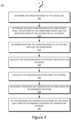
Figure 4 is a flowchart of a method for resetting a discharge air setpoint temperature in an HVACR system, according to an embodiment. -
Figure 5 is a flowchart of a method for resetting a discharge air setpoint temperature in an HVACR system, according to an embodiment. - Like reference numbers represent like parts throughout.
- This disclosure relates generally to a heating, ventilation, air conditioning, and refrigeration (HVACR) system. More specifically, the invention relates to a method for controlling a discharge air reset for a HVACR system and to a HVACR system implementing the method.
- Buildings are designed with a variety of HVACR system types. One type of HVACR system includes a rooftop unit to provide conditioned air to an air distribution system that includes ductwork, variable-air-volume (VAV) boxes, and diffusers. The VAV boxes provide a variable amount of conditioned air to a space based on the temperature and ventilation requirements of that space.
- Some rooftop units deliver a constant volume of air. These systems are commonly known as changeover bypass systems. With changeover bypass systems, the rooftop unit provides either relatively cold or relatively warm air to the VAV boxes. When the majority of spaces need cooling capability, the rooftop unit operates in the cooling mode - normally providing a default discharge air of 13°C (55 °F) air to the VAV boxes. When the majority of spaces need heating, the rooftop unit changes to the heating mode - normally providing a default discharge air of 41°C (105 °F) air to the VAV boxes. Because the rooftop unit is capable of proving only cold or warm air, the system changes between the cooling and heating modes to temporarily satisfy the needs of each space.
- Embodiments of this invention are directed to modifying a temperature of the discharge air according to a statistical deviation of a space temperature of the conditioned spaces from a setpoint temperature of the conditioned spaces.
- A "statistical deviation" of a space temperature of the conditioned spaces from a setpoint temperature of the conditioned spaces, as used in this Specification, is a single measure of an attribute of a sample. In an embodiment, the statistical deviation is an average. In an embodiment, the statistical deviation is a maximum. In an embodiment, the statistical deviation may include a mean, mode, and/or median, or the like.
- Embodiments of this invention are directed to modifying a temperature of the discharge air according to an average deviation of a space temperature of the conditioned spaces from a setpoint temperature of the conditioned spaces. The modified discharge air temperature can, for example, enable the rooftop unit to input less energy in heating or cooling the airflow when the cooling or heating loads are relatively lower (as determined by the average deviation).
- In an embodiment, utilizing the maximum deviation of the space temperature of the conditioned spaces from the setpoint temperature of the conditioned spaces can result in a more responsive control of the space temperature in the conditioned spaces. That is, the control can result in a more precise climate control for the HVACR system by enabling a faster response to outlier conditions (e.g., conditioned spaces which are not at the setpoint temperature).
-
Figure 1 is a schematic of anHVACR system 10, according to an embodiment. TheHVACR system 10 is generally representative of a constant volume changeover bypass HVACR system. - The
HVACR system 10 includes anHVACR unit 15. In an embodiment, theHVACR unit 15 may be a rooftop unit. TheHVACR unit 15 generally includes a refrigeration circuit (not shown) including a compressor, condenser, expander, and evaporator fluidly connected. The refrigeration circuit operates according to generally known principles to condition an airflow output from theHVACR unit 15. The conditioned airflow can have, for example, a controlled temperature, humidity, or the like. - In an embodiment, the
HVACR unit 15 may be able to output an airflow at various temperatures. TheHVACR unit 15 can be operable in a cooling mode and in a heating mode. In the cooling mode, the airflow can be conditioned to provide a relatively cooler temperature to the airflow than the heating mode. Similarly, in the heating mode, the airflow can be conditioned to provide a relatively warmer temperature to the airflow than the cooling mode. - In an embodiment, the
HVACR unit 15 may be able to output an airflow that is at or about 13°C (55 °F) in the cooling mode. In an embodiment, theHVACR unit 15 may be able to output an airflow that is relatively cooler than at or about 13°C (55 °F) or relatively warmer than at or about 13°C (55 °F) when in the cooling mode. For example, theHVACR unit 15 may be able to output an airflow that is from at or about 7.2°C (45 °F) to at or about 18°C (65 °F). It is to be appreciated that these numbers are examples and that the actual capabilities can vary beyond the stated temperatures. - In an embodiment, the
HVACR unit 15 may be able to output an airflow that is at or about 41°C (105 °F) in the heating mode. In an embodiment, theHVACR unit 15 may be able to output an airflow that is relatively cooler than at or about 41°C (105 °F) or relatively warmer than at or about 41°C (105 °F) when in the heating mode. For example, theHVACR unit 15 may be able to output an airflow that is from at or about 27°C (80 °F) to at or about 46°C (115 °F). It is to be appreciated that these numbers are examples and that the actual capabilities can vary beyond the stated temperatures. - The
HVACR unit 15 provides the conditioned air viaductwork 20 to a plurality of conditionedspaces 25. Theconditioned spaces 25 can alternatively be referred to as thezones 25 or the like. - Each of the plurality of conditioned
spaces 25 includes a variable air volume (VAV)box 30 and asensor 35. TheVAV box 30 can be selectively controlled for each space to meet an environmental requirement. In an embodiment, the environmental requirement can be, for example, a temperature setpoint. TheVAV box 30 can include a damper that can be modulated in response to a measurement from thesensor 35 that is indicative of whether the environment in the conditionedspace 25 is meeting the environmental requirement. The damper can control an amount of the conditioned airflow that is provided to the conditionedspaces 25. - When one of the conditioned
spaces 25 requires cooling and theHVACR unit 15 is in the cooling mode, theVAV box 30 for that space modulates to deliver more or less conditioned air to thespace 25 to control the temperature. In an embodiment, eachVAV box 30 can have a minimum airflow requirement to provide proper ventilation to the conditionedspace 25. When one of the conditionedspaces 25 requires cooling from theHVACR unit 15 but theHVACR unit 15 is in the heating mode, theVAV box 30 is controlled to reduce the airflow to the minimum flow that meets the ventilation requirement. The signal to thecontroller 40 requesting cooling from the correspondingVAV box 30 can be counted. Once a majority of theVAV boxes 30 are calling for cooling, thecontroller 40 can switch the mode of theHVACR unit 15. -
Controller 40 can control theHVACR unit 15 as well as theVAV boxes 30. Thecontroller 40 is in electronic communication with theHVACR unit 15, theVAV boxes 30, and thesensors 35. For illustrative purposes, these electronic connections are illustrated in dashed lines. It is to be appreciated that the electronic communication between the various components can be through a wired or a wireless connection. - The
HVACR unit 15 may deliver a relatively constant volume of air through theductwork 20. To balance a volume of air delivered to the conditionedspaces 25, abypass damper 45 can be included at a location that is downstream of theHVACR unit 15 and upstream of the conditionedspaces 25. - In operation, the
HVACR unit 15 either operates in the cooling mode to provide relatively cool air to the conditionedspaces 25 or in the heating mode to provide relatively warmer air to the conditionedspaces 25. Thecontroller 40 can selectively switch theHVACR unit 15 between the cooling mode and the heating mode based on what a majority of the conditionedspaces 25 require. As a result, theHVACR unit 15 can cycle back-and-forth between the heating mode and the cooling mode depending upon the needs of the conditioned spaces. The constant switching can be relatively inefficient. The control methods described inFigures 2 and3 below can adjust a discharge air temperature of theHVACR unit 15 from a default discharge air temperature (e.g., 13°C [55 °F] or 41°C [105 °F] or the like) to reduce an amount of cycling of the modes of theHVACR unit 15. In an embodiment, this can reduce an amount of energy consumed by theHVACR unit 15. -
Figure 2 is a flowchart of amethod 100 for resetting a discharge air setpoint temperature in an HVACR system (e.g., theHVACR system 10 inFigure 1 ), according to an embodiment. Themethod 100 includes determining a statistical deviation from a setpoint temperature for a plurality of VAV boxes and using the statistical deviation to determine a discharge air setpoint temperature for the conditioned air being provided by an HVACR unit. In themethod 100, the statistical deviation includes an average deviation. It is to be appreciated that the statistical deviation can, in an embodiment, utilize a maximum deviation (e.g.,Figures 4 ,5 ) or the like. - The
method 100 generally includes determining an average deviation from a setpoint temperature for a plurality of VAV boxes (e.g., theVAV boxes 30 inFigure 1 ) and using the average deviation to determine a discharge air setpoint temperature for the conditioned air being provided by an HVACR unit (e.g., theHVACR unit 15 inFigure 1 ) in theHVACR system 10. In an embodiment, themethod 100 can be performed whenever theHVACR system 10 is operational. In an embodiment, themethod 100 can be a mode of operation that can be scheduled or otherwise selectively performed. For example, a building operator may be able to define one or more rules regarding when to perform the method 100 (e.g., during occupied times, unoccupied times, or the like). - In an embodiment, the
method 100 can allow the discharge air setpoint temperature of theHVACR unit 15 to vary so that, for example, an amount of switching between a cooling mode and a heating mode of theHVACR unit 15 is reduced. In an embodiment, allowing the discharge air setpoint temperature to vary can also reduce an amount of energy consumed by theHVACR unit 15 in providing the conditioned air to conditioned spaces (e.g., conditionedspaces 25 inFigure 1 ) of a building. - At 105, a controller (e.g., the
controller 40 inFigure 1 ) of theHVACR system 10 determines an operating mode of theHVACR unit 15. The operating mode of theHVACR unit 15 can include a heating mode or a cooling mode. In operation, the cooling mode can result in provision of air at a default discharge air setpoint temperature of at or about 13°C (55 °F), for example. The heating mode can result in provision of air at a default discharge air setpoint temperature of at or about 41°C (105 °F), for example. - At 110, the
controller 40 determines a space temperature in the conditionedspaces 25 of theHVACR system 10, a setpoint temperature of the conditionedspaces 25, and an operating mode of theVAV boxes 30 in the conditionedspaces 25. - At 110, the
controller 40 may determine the space temperature, the setpoint temperature of the conditioned space, and the operating mode for allVAV boxes 30 and correspondingconditioned spaces 25 being controlled by theHVACR system 10. In response to 110, thecontroller 40 may have the setpoint temperature of the conditioned space, operating mode, and space temperature for every VAV box in theHVACR system 10. - At 115, the
controller 40 determines whether the operating mode determined at 110 of theVAV boxes 30 matches the operating mode of theHVACR unit 15 as determined at 105. In the illustrated embodiment, 115 is shown in dashed lines as being optional. - At 120, the
controller 40 calculates a deviation from the setpoint temperature for theVAV boxes 30. In an embodiment in which 115 is performed, themethod 100 may include calculating the deviation from the setpoint temperature only for thoseVAV boxes 30 which have the same operating mode as the operating mode of theHVACR unit 15. In such an embodiment, if, at 115, the operating mode for aparticular VAV box 30 does not match the operating mode for theHVACR unit 15, the information surrounding setpoint temperature and space temperature for the corresponding conditionedspace 25 is considered to be irrelevant to the discharge air temperature reset for the current mode. - In an embodiment, at 120, the
controller 40 may calculate a deviation from the setpoint temperature for allVAV boxes 30, regardless of the operating mode. Such an embodiment may, for example, occur when 115 is not performed. - While these
VAV boxes 30 may be ignored for purposes of the discharge air setpoint temperature determination, if a majority of theVAV boxes 30 have an operating mode that does not match the operating mode of theHVACR unit 15, then the operating mode of theHVACR unit 15 may be accordingly switched. - In general, a deviation from the setpoint for each of the
VAV boxes 30 includes calculating a difference between the setpoint temperature as determined at 110 and the space temperature in the conditionedspace 25 as determined at 110. - At 125, the
controller 40 calculates an average deviation from the setpoint temperature based on the deviation from the setpoint temperature for the VAV boxes collectively. In an embodiment, this will include averaging (e.g., finding a mean) the deviation from the setpoint temperature for each of theVAV boxes 30 as determined at 120. In an embodiment, the control could be based on a different statistical deviation determination, such as a maximum, a median, or a mode of the collective deviations from the setpoint temperature. - At 130, the controller determines a discharge air setpoint temperature based on the average deviation from the setpoint temperature as determined at 125. In an embodiment, the discharge air setpoint temperature can be determined based on a relationship established between the average deviation and a range of discharge air setpoint temperatures. For example, a discharge air temperature variation range can be set to be from at or about 13°C (55 °F) to at or about 24°C (75 °F) when operating in the cooling mode and from at or about 41°C (105 °F) to at or about 27°C (80 °F) when operating in the heating mode.
- In the cooling mode, a relationship can be drawn such that at an average deviation from the setpoint temperature of at or about -0.6°C (-1 °F) the discharge air setpoint temperature may be selected to be a modified discharge air setpoint temperature of at or about 24°C (75 °F) and at an average deviation from the setpoint temperature of at or about 1.7°C (3 °F) the discharge air setpoint temperature may be selected to be the default discharge air setpoint temperature of at or about 13°C (55 °F). In an embodiment, between at or about -0.6°C (-1 °F) and at or about 1.7°C (3 °F), the discharge temperature setpoint can vary linearly between at or about 24°C (75 °F) and at or about 13°C (55 °F). In an embodiment, between at or about -0.6°C (-1 °F) and at or about 1.7°C (3 °F), the discharge temperature setpoint can vary according to a non-linear relationship between at or about 24°C (75 °F) and at or about 13°C (55 °F).
- In an embodiment, a positive deviation from the setpoint temperature can be representative of a situation in which the space temperature is above the setpoint temperature when in the cooling mode. In an embodiment, a positive deviation from the setpoint temperature can be representative of a situation in which the space temperature is below the setpoint temperature when in the heating mode.
- In an embodiment, a negative deviation from the setpoint temperature can be representative of a situation in which the space temperature is below the setpoint temperature when in the cooling mode. In an embodiment, a negative deviation from the setpoint temperature can be representative of a situation in which the space temperature is above the setpoint temperature when in the heating mode.
- In an embodiment, negative deviations from the setpoint may be ignored. In such an embodiment, a discharge air setpoint temperature may be reset prior to the setpoint temperature being reached. In an embodiment in which negative deviations from the setpoint temperature are enabled, a relatively greater emphasis may be placed on maintaining setpoint control until the setpoint temperature is reached.
- In the heating mode, a relationship can be drawn such that at an average deviation from the setpoint temperature of at or about -0.6°C (-1 °F) the discharge air setpoint temperature may be selected to be a modified discharge air setpoint temperature of at or about 27°C (80 °F) and at an average deviation from the setpoint temperature of at or about 1.7°C (3 °F) the discharge air setpoint temperature may be selected to be a default discharge air setpoint temperature of at or about 41°C (105 °F). In an embodiment, between at or about -0.6°C (-1 °F) and at or about 1.7°C (3 °F), the discharge air setpoint temperature can vary linearly between at or about 27°C (80 °F) and at or about 41°C (105 °F). In an embodiment, between at or about -0.6°C (-1 °F) and at or about 1.7°C (3 °F), the discharge air setpoint temperature can vary according to a non-linear relationship between at or about 27°C (80 °F) and at or about 41°C (105 °F).
- At 135, the
controller 40 sets the discharge air setpoint temperature of theHVACR unit 15 using the discharge temperature setpoint as determined at 130. -
Figure 3 is a flowchart of amethod 150 for resetting a discharge air setpoint temperature in an HVACR system (e.g., theHVACR system 10 inFigure 1 ), according to an embodiment. - The
method 150 inFigure 3 can include one or more additional aspects relative to themethod 100 inFigure 2 . Themethod 150 can include performing themethod 100. In an embodiment, themethod 150 can generally include a humidity management consideration on top of the discharge air setpoint temperature modification in themethod 100. The humidity management operation may maintain conditioned spaces (e.g., the conditionedspaces 25 inFigure 1 ) at a particular humidity level. Accordingly, themethod 150 may balance the dischargeair reset method 100 inFigure 2 with a humidity control consideration. - At 155, a controller (e.g., the
controller 40 inFigure 1 ) of theHVACR system 10 determines a humidity control mode. In an embodiment, there can be multiple humidity control modes. For example, in a first humidity control mode (an active mode), the humidity can be maintained at or below a setpoint humidity as determined from a sensor (e.g., thesensor 35 in the conditioned space 25). In another mode (a passive mode), the humidity can be controlled based on limiting according to a temperature of the airflow being provided to the conditionedspace 25. Such an embodiment may be considered a passive humidity control, as the discharge air setpoint temperature is limited based on humidity regardless of a measured humidity in the conditioned space. - If the humidity control mode is passive, then at 160 the
controller 40 determines a maximum humidity value for the conditionedspace 25. The maximum humidity value can be, for example, based on a setting of the user, a standard, or the like. - At 165, the
controller 40 determines a discharge air setpoint temperature based on the maximum humidity value. Themethod 150 can then proceed to performing themethod 100 to determine a discharge air setpoint temperature based on the average deviation from the setpoint temperature as discussed above with respect to themethod 100 inFigure 2 . - At 180, the
controller 40 can compare a discharge air setpoint temperature with the humidity based temperature setpoint as determined at 165. Thecontroller 40 selects a lower threshold of or selects a lowest discharge air setpoint temperature based on these two setpoints, and sets the discharge air setpoint temperature of theHVACR unit 15 to the lower threshold or lowest as selected at 180. At 185, thecontroller 40 resets the discharge air setpoint temperature of theHVACR unit 15 using the discharge temperature setpoint as determined at 180. - If the humidity control is operating in the active mode, at 170 the
controller 40 determines whether the humidity in the conditionedspace 25 is equal to or exceeds a humidity setpoint. If yes, then the discharge air setpoint temperature at 175 is maintained at the default discharge air setpoint temperature (e.g., at 13°C [55 °F]) until the humidity requirement is met. If the humidity is below the humidity setpoint, then the method continues with the discharge air setpoint temperature determination of the method 100 (as described with respect toFigure 2 above). -
Figure 4 is a flowchart of amethod 200 for resetting a discharge air setpoint temperature in an HVACR system (e.g., theHVACR system 10 inFigure 1 ), according to an embodiment. Themethod 200 includes determining a statistical deviation from a setpoint temperature for a plurality of VAV boxes and using the statistical deviation to determine a discharge air setpoint temperature for the conditioned air being provided by an HVACR unit. In themethod 200, the statistical deviation includes a maximum deviation. It is to be appreciated that the statistical deviation can, in an embodiment, utilize an average deviation (e.g.,Figures 2 ,3 ) or the like. - The
method 200 generally includes determining a maximum deviation from a setpoint temperature for a plurality of VAV boxes (e.g., theVAV boxes 30 inFigure 1 ) and using the maximum deviation to determine a discharge air setpoint temperature for the conditioned air being provided by an HVACR unit (e.g., theHVACR unit 15 inFigure 1 ) in theHVACR system 10. In an embodiment, themethod 200 can be performed whenever theHVACR system 10 is operational. In an embodiment, themethod 200 can be a mode of operation that can be scheduled or otherwise selectively performed. For example, a building operator may be able to define one or more rules regarding when to perform the method 200 (e.g., during occupied times, unoccupied times, or the like). - In an embodiment, the
method 200 can allow the discharge air setpoint temperature of theHVACR unit 15 to vary so that, for example, an amount of switching between a cooling mode and a heating mode of theHVACR unit 15 is reduced. In an embodiment, allowing the discharge air setpoint temperature to vary can also reduce an amount of energy consumed by theHVACR unit 15 in providing the conditioned air to conditioned spaces (e.g., conditionedspaces 25 inFigure 1 ) of a building. - At 205, a controller (e.g., the
controller 40 inFigure 1 ) of theHVACR system 10 determines an operating mode of theHVACR unit 15. The operating mode of theHVACR unit 15 can include a heating mode or a cooling mode. In operation, the cooling mode can result in provision of air at a default discharge air setpoint temperature of at or about 13°C (55 °F), for example. The heating mode can result in provision of air at a default discharge air setpoint temperature of at or about 96°C (205 °F), for example. - At 210, the
controller 40 determines a space temperature in the conditionedspaces 25 of theHVACR system 10, a setpoint temperature of the conditionedspaces 25, and an operating mode of theVAV boxes 30 in the conditionedspaces 25. - At 210, the
controller 40 may determine the space temperature, the setpoint temperature of the conditioned space, and the operating mode for allVAV boxes 30 and correspondingconditioned spaces 25 being controlled by theHVACR system 10. In response to 210, thecontroller 40 may have the setpoint temperature of the conditioned space, operating mode, and space temperature for every VAV box in theHVACR system 10. - At 215, the
controller 40 determines whether the operating mode determined at 210 of theVAV boxes 30 matches the operating mode of theHVACR unit 15 as determined at 205. In the illustrated embodiment, 215 is shown in dashed lines as being optional. - At 220, the
controller 40 calculates a deviation from the setpoint temperature for theVAV boxes 30. In an embodiment in which 215 is performed, themethod 200 may include calculating the deviation from the setpoint temperature only for thoseVAV boxes 30 which have the same operating mode as the operating mode of theHVACR unit 15. In such an embodiment, if, at 215, the operating mode for aparticular VAV box 30 does not match the operating mode for theHVACR unit 15, the information surrounding setpoint temperature and space temperature for the corresponding conditionedspace 25 is considered to be irrelevant to the discharge air temperature reset for the current mode. - In an embodiment, at 220, the
controller 40 may calculate a deviation from the setpoint temperature for allVAV boxes 30, regardless of the operating mode. Such an embodiment may, for example, occur when 215 is not performed. - While these
VAV boxes 30 may be ignored for purposes of the discharge air setpoint temperature determination, if a majority of theVAV boxes 30 have an operating mode that does not match the operating mode of theHVACR unit 15, then the operating mode of theHVACR unit 15 may be accordingly switched. - In general, a deviation from the setpoint for each of the
VAV boxes 30 includes calculating a difference between the setpoint temperature as determined at 210 and the space temperature in the conditionedspace 25 as determined at 210. - At 225, the
controller 40 calculates a maximum deviation from the setpoint temperature based on the deviation from the setpoint temperature for the VAV boxes collectively. In an embodiment, this will include identifying the relatively largest deviation from the setpoint temperature among theVAV boxes 30 as determined at 220. In an embodiment, the control could be based on a different statistical determination, such as an average (e.g., mean), median, a mode, or the like of the collective deviations from the setpoint temperature. - At 230, the controller determines a discharge air setpoint temperature based on the maximum deviation from the setpoint temperature as determined at 225. In an embodiment, the discharge air setpoint temperature can be determined based on a relationship established between the maximum deviation and a range of discharge air setpoint temperatures. For example, a discharge air temperature variation range can be set to be from at or about 13°C (55 °F) to at or about 24°C (75 °F) when operating in the cooling mode and from at or about 96°C (205 °F) to at or about 27°C (80 °F) when operating in the heating mode.
- In the cooling mode, a relationship can be drawn such that at a maximum deviation from the setpoint temperature of at or about -0.6°C (-1 °F) the discharge air setpoint temperature may be selected to be a modified discharge air setpoint temperature of at or about 24°C (75 °F) and at a maximum deviation from the setpoint temperature of at or about 1.7°C (3 °F) the discharge air setpoint temperature may be selected to be the default discharge air setpoint temperature of at or about 13°C (55 °F). In an embodiment, between at or about -0.6°C (-1 °F) and at or about 1.7°C (3 °F), the discharge temperature setpoint can vary linearly between at or about 24°C (75 °F) and at or about 13°C (55 °F). In an embodiment, between at or about -0.6°C (-1 °F) and at or about 1.7°C (3 °F), the discharge temperature setpoint can vary according to a non-linear relationship between at or about 24°C (75 °F) and at or about 13°C (55 °F).
- In an embodiment, a positive deviation from the setpoint temperature can be representative of a situation in which the space temperature is above the setpoint temperature when in the cooling mode. In an embodiment, a positive deviation from the setpoint temperature can be representative of a situation in which the space temperature is below the setpoint temperature when in the heating mode.
- In an embodiment, a negative deviation from the setpoint temperature can be representative of a situation in which the space temperature is below the setpoint temperature when in the cooling mode. In an embodiment, a negative deviation from the setpoint temperature can be representative of a situation in which the space temperature is above the setpoint temperature when in the heating mode.
- In an embodiment, negative deviations from the setpoint may be ignored. In such an embodiment, a discharge air setpoint temperature may be reset prior to the setpoint temperature being reached. In an embodiment in which negative deviations from the setpoint temperature are enabled, a relatively greater emphasis may be placed on maintaining setpoint control until the setpoint temperature is reached.
- In the heating mode, a relationship can be drawn such that at a maximum deviation from the setpoint temperature of at or about -0.6°C (-1 °F) the discharge air setpoint temperature may be selected to be a modified discharge air setpoint temperature of at or about 27°C (80 °F) and at a maximum deviation from the setpoint temperature of at or about 1.7°C (3 °F) the discharge air setpoint temperature may be selected to be a default discharge air setpoint temperature of at or about 96°C (205 °F). In an embodiment, between at or about -0.6°C (-1 °F) and at or about 1.7°C (3 °F), the discharge air setpoint temperature can vary linearly between at or about 27°C (80 °F) and at or about 96°C (205 °F). In an embodiment, between at or about -0.6°C (-1 °F) and at or about 1.7°C (3 °F), the discharge air setpoint temperature can vary according to a non-linear relationship between at or about 27°C (80 °F) and at or about 96°C (205 °F).
- At 235, the
controller 40 sets the discharge air setpoint temperature of theHVACR unit 15 using the discharge temperature setpoint as determined at 230. -
Figure 5 is a flowchart of amethod 250 for resetting a discharge air setpoint temperature in an HVACR system (e.g., theHVACR system 10 inFigure 1 ), according to an embodiment. - The
method 250 inFigure 5 can include one or more additional aspects relative to themethod 200 inFigure 4 . Themethod 250 can include performing themethod 200. In an embodiment, themethod 250 can generally include a humidity management consideration on top of the discharge air setpoint temperature modification in themethod 200. The humidity management operation may maintain conditioned spaces (e.g., the conditionedspaces 25 inFigure 1 ) at a particular humidity level. Accordingly, themethod 250 may balance the dischargeair reset method 200 inFigure 4 with a humidity control consideration. - At 255, a controller (e.g., the
controller 40 inFigure 1 ) of theHVACR system 10 determines a humidity control mode. In an embodiment, there can be multiple humidity control modes. For example, in a first humidity control mode (an active mode), the humidity can be maintained at or below a setpoint humidity as determined from a sensor (e.g., thesensor 35 in the conditioned space 25). In another mode (a passive mode), the humidity can be controlled based on limiting according to a temperature of the airflow being provided to the conditionedspace 25. Such an embodiment may be considered a passive humidity control, as the discharge air setpoint temperature is limited based on humidity regardless of a measured humidity in the conditioned space. - If the humidity control mode is passive, then at 260 the
controller 40 determines a maximum humidity value for the conditionedspace 25. The maximum humidity value can be, for example, based on a setting of the user, a standard, or the like. - At 265, the
controller 40 determines a discharge air setpoint temperature based on the maximum humidity value. Themethod 250 can then proceed to performing themethod 200 to determine a discharge air setpoint temperature based on the maximum deviation from the setpoint temperature as discussed above with respect to themethod 200 inFigure 4 . - At 280, the
controller 40 can compare a discharge air setpoint temperature with the humidity based temperature setpoint as determined at 265. Thecontroller 40 selects a lower threshold of or selects a lowest discharge air setpoint temperature based on these two setpoints, and sets the discharge air setpoint temperature of theHVACR unit 15 to the lower threshold or lowest as selected at 280. At 285, thecontroller 40 resets the discharge air setpoint temperature of theHVACR unit 15 using the discharge temperature setpoint as determined at 280. - If the humidity control is operating in the active mode, at 270 the
controller 40 determines whether the humidity in the conditionedspace 25 is equal to or exceeds a humidity setpoint. If yes, then the discharge air setpoint temperature at 275 is maintained at the default discharge air setpoint temperature (e.g., at 13°C [55 °F]) until the humidity requirement is met. If the humidity is below the humidity setpoint, then the method continues with the discharge air setpoint temperature determination of the method 200 (as described with respect toFigure 4 above). - The terminology used in this specification is intended to describe particular embodiments and is not intended to be limiting. The terms "a," "an," and "the" include the plural forms as well, unless clearly indicated otherwise. The terms "comprises" and/or "comprising," when used in this specification, specify the presence of the stated features, integers, steps, operations, elements, and/or components, but do not preclude the presence or addition of one or more other features, integers, steps, operations, elements, and/or components.
- With regard to the preceding description, it is to be understood that changes may be made in detail, especially in matters of the construction materials employed and the shape, size, and arrangement of parts without departing from the scope of the present invention. This specification and the embodiments described are exemplary only, with the true scope of the invention being indicated by the claims that follow.
Claims (11)
- A method (100; 200) of controlling a discharge air reset in a heating, ventilation, air conditioning, and refrigeration (HVACR) system (10) that includes an HVACR unit (15) configured to provide conditioned air to a plurality of conditioned spaces, the method comprising:for each of the plurality of conditioned spaces (25), determining (110; 210), by a controller (40), a space temperature in the conditioned space, a setpoint temperature of the conditioned space, and an operating mode of a respective variable-air-volume (VAV) box (30) for the conditioned space;for each of a plurality of the conditioned spaces, calculating (120; 220) a deviation of the space temperature of the conditioned space from the setpoint temperature of the conditioned space for the VAV box for the conditioned space;calculating (125; 225) a statistical deviation from the setpoint temperatures of the conditioned spaces based on the calculated deviations;determining (130; 230) a discharge air setpoint temperature based on the statistical deviation from the setpoint temperatures of the conditioned spaces; andsetting (135; 235) the discharge air setpoint temperature of the HVACR unit of the HVACR system using the determined discharge air setpoint temperature.
- The method (100; 200) of claim 1, further comprising:determining (115; 215) whether the respective operating modes of each of the VAV boxes (30) matches an operating mode of the HVACR unit (15); andcalculating (120; 220) a deviation from the setpoint temperature of the conditioned space (25) for the VAV box for the conditioned space when the operating mode of the VAV box matches the operating mode of the HVACR unit.
- The method (100; 200) of any one of claims 1-2, further comprising:
for each of the plurality of conditioned spaces (25), determining (165; 265) a second discharge air setpoint temperature based on a maximum humidity for the conditioned space, and setting the discharge air setpoint temperature to be the second discharge air setpoint temperature when the second discharge air setpoint temperature is less than the discharge air setpoint temperature based on the statistical deviation from the setpoint temperatures of the conditioned spaces. - The method (100; 200) of any one of claims 1-3, further comprising:
for each of the plurality of conditioned spaces (25), determining a humidity in the conditioned space, wherein in response to determining the humidity in the conditioned space is greater than or equal to a threshold humidity, the discharge air setpoint temperature is maintained at a default discharge air setpoint temperature. - The method (100; 200) of any one of claims 1-4, wherein the discharge air setpoint temperature based on the statistical deviation from the setpoint temperatures of the conditioned spaces (25) varies linearly between a default discharge air setpoint temperature and a modified discharge air setpoint temperature.
- The method (100; 200) of claim 5, wherein the default discharge air temperature is at or about 13°C (55 °F) when the operating mode of the HVACR unit (15) is a cooling mode.
- The method (100; 200) of claim 6, wherein the modified discharge air setpoint temperature is at or about 18°C (65 °F) when the operating mode of the HVACR unit (15) is the cooling mode.
- The method (100; 200) of claim 5, wherein the default discharge air temperature is at or about 41°C (105 °F) when the operating mode of the HVACR unit (15) is a heating mode.
- The method (100; 200) of claim 8, wherein the modified discharge air setpoint temperature is at or about 27°C (80 °F) when the operating mode of the HVACR unit (15) is the heating mode.
- The method (100; 200) of any one of claims 1-9, wherein the statistical deviation from the setpoint temperatures of the conditioned spaces (25) is an average calculation or a maximum calculation.
- A heating, ventilation, air conditioning, and refrigeration (HVACR) system (10), comprising:a plurality of conditioned spaces (25), each of the plurality of conditioned spaces including a variable-air-volume (VAV) box (30) and a sensor (35);an HVACR unit (15) operable in a heating mode and a cooling mode, the HVACR unit being configured to provide conditioned air to the plurality of conditioned spaces;
anda controller (40) in electronic communication with the HVACR unit, the VAV boxes (30), and the sensors (35), the controller configured to perform the method of any of the preceding claims.
Applications Claiming Priority (2)
| Application Number | Priority Date | Filing Date | Title |
|---|---|---|---|
| US16/233,931 US10876752B2 (en) | 2018-12-27 | 2018-12-27 | Discharge air reset for a constant volume air changeover bypass |
| US16/246,211 US10876756B2 (en) | 2018-12-27 | 2019-01-11 | Discharge air reset for a constant volume air changeover bypass |
Publications (2)
| Publication Number | Publication Date |
|---|---|
| EP3674614A1 EP3674614A1 (en) | 2020-07-01 |
| EP3674614B1 true EP3674614B1 (en) | 2023-12-06 |
Family
ID=68944574
Family Applications (1)
| Application Number | Title | Priority Date | Filing Date |
|---|---|---|---|
| EP19217402.7A Active EP3674614B1 (en) | 2018-12-27 | 2019-12-18 | Discharge air temperature reset for hvacr unit operating variable-air-volume box |
Country Status (3)
| Country | Link |
|---|---|
| US (1) | US10876756B2 (en) |
| EP (1) | EP3674614B1 (en) |
| CN (1) | CN111380186B (en) |
Family Cites Families (17)
| Publication number | Priority date | Publication date | Assignee | Title |
|---|---|---|---|---|
| US6220518B1 (en) * | 1999-05-13 | 2001-04-24 | Acutherm L.P. | Process and apparatus for individual adjustment of the temperature set points of a plurality of VAV devices |
| US6298912B1 (en) * | 1999-06-22 | 2001-10-09 | York International Corporation | Method and system for controlling an economizer |
| US6296193B1 (en) | 1999-09-30 | 2001-10-02 | Johnson Controls Technology Co. | Controller for operating a dual duct variable air volume terminal unit of an environmental control system |
| AU2002365546B2 (en) * | 2001-11-30 | 2008-05-29 | National University Of Singapore | Energy-efficient variable-air volume (VAV) system with zonal ventilation control |
| US7496472B2 (en) * | 2007-01-25 | 2009-02-24 | Johnson Controls Technology Company | Method and system for assessing performance of control systems |
| US8484990B2 (en) * | 2007-02-14 | 2013-07-16 | Carrier Corporation | Optimization of air cooled chiller system operation |
| US8190273B1 (en) | 2008-04-18 | 2012-05-29 | Federspiel Corporation | Method and apparatus for controlling fans in heating, ventilating, and air-conditioning systems |
| CN101672509A (en) * | 2009-09-02 | 2010-03-17 | 东莞市广大制冷有限公司 | Variable air volume air conditioner control technology based on enthalpy value control |
| CN101806484B (en) * | 2010-04-06 | 2012-05-23 | 南京航空航天大学 | air-conditioner control system of variable frequency fan and digital air valve for adjusting tail end air volume and method thereof |
| KR20130098346A (en) * | 2010-08-20 | 2013-09-04 | 비질런트 코포레이션 | Energy-optimal control decisions for hvac systems |
| JP6355342B2 (en) * | 2014-01-28 | 2018-07-11 | 株式会社クボタ | Agricultural air conditioner |
| US10801508B2 (en) * | 2014-12-30 | 2020-10-13 | Delta T, Llc | Integrated thermal comfort control system with variable mode of operation |
| US10866572B2 (en) | 2016-04-27 | 2020-12-15 | Johnson Controls Technology Company | Selectable variable air volume controller |
| US10072862B2 (en) * | 2016-06-09 | 2018-09-11 | Lennox Industries Inc. | Method and system for optimizing a speed of at least one of a variable speed compressor and a variable speed circulation fan to improve latent capacity |
| SG10201605828UA (en) * | 2016-07-15 | 2018-02-27 | Barghest Building Performance Pte Ltd | Method for improving operational efficiency of a cooling system through retrofitting a building with a master controller |
| CN108151246A (en) * | 2017-12-13 | 2018-06-12 | 长安大学 | Air quantity variable air conditioner wind system Optimization of Energy Saving control method and device |
| CN108954711A (en) * | 2018-07-23 | 2018-12-07 | 江苏景源泓科技有限公司 | A kind of centralization automatic control system |
-
2019
- 2019-01-11 US US16/246,211 patent/US10876756B2/en active Active
- 2019-12-18 EP EP19217402.7A patent/EP3674614B1/en active Active
- 2019-12-27 CN CN201911382516.6A patent/CN111380186B/en active Active
Also Published As
| Publication number | Publication date |
|---|---|
| EP3674614A1 (en) | 2020-07-01 |
| CN111380186A (en) | 2020-07-07 |
| US10876756B2 (en) | 2020-12-29 |
| CN111380186B (en) | 2023-04-14 |
| US20200208865A1 (en) | 2020-07-02 |
Similar Documents
| Publication | Publication Date | Title |
|---|---|---|
| US6879881B1 (en) | Variable air volume system including BTU control function | |
| US11879658B2 (en) | Air-conditioning ventilation system | |
| US10753664B2 (en) | Method and apparatus for reheat dehumidification with variable speed outdoor fan | |
| JP2018109458A (en) | Control device for air conditioning system and air conditioning system | |
| CN108644968B (en) | Control method for air conditioning system | |
| JP2016196971A (en) | Air conditioner | |
| US10876752B2 (en) | Discharge air reset for a constant volume air changeover bypass | |
| CN108592353B (en) | Control method for air conditioning system | |
| CN108826599B (en) | Control method for air conditioning system | |
| EP3674614B1 (en) | Discharge air temperature reset for hvacr unit operating variable-air-volume box | |
| US11454411B2 (en) | Zone air flow rate adjustment for an HVAC system | |
| US11105529B2 (en) | Multi-zone indoor climate control and a method of using the same | |
| JP2013015314A (en) | Air conditioning system, air conditioning control apparatus and air conditioning control program | |
| EP3764012B1 (en) | High pressure drop control method for unit, apparatus, and air-conditioning device | |
| US20160349772A1 (en) | Coordinated control of hvac system using aggregated system demand | |
| EP3707438B1 (en) | Control system for hvac comprising an air-handling unit and a terminal unit and method of operating said control system | |
| JPH07151419A (en) | Heat pump device | |
| CN115151098A (en) | Inter-column air conditioner control method, inter-column air conditioner, electronic device, and readable storage medium | |
| CN113639388A (en) | Method and device for controlling air conditioner air outlet in machine room, air conditioner and storage medium | |
| US20240318853A1 (en) | Control systems for heating ventilation and cooling systems | |
| JPH0518594A (en) | Air conditioning system | |
| CN119196905A (en) | Control method and related equipment for secondary return air constant temperature and humidity air conditioning unit | |
| AU2004242427A1 (en) | Airconditioning system |
Legal Events
| Date | Code | Title | Description |
|---|---|---|---|
| PUAI | Public reference made under article 153(3) epc to a published international application that has entered the european phase |
Free format text: ORIGINAL CODE: 0009012 |
|
| STAA | Information on the status of an ep patent application or granted ep patent |
Free format text: STATUS: THE APPLICATION HAS BEEN PUBLISHED |
|
| AK | Designated contracting states |
Kind code of ref document: A1 Designated state(s): AL AT BE BG CH CY CZ DE DK EE ES FI FR GB GR HR HU IE IS IT LI LT LU LV MC MK MT NL NO PL PT RO RS SE SI SK SM TR |
|
| AX | Request for extension of the european patent |
Extension state: BA ME |
|
| STAA | Information on the status of an ep patent application or granted ep patent |
Free format text: STATUS: REQUEST FOR EXAMINATION WAS MADE |
|
| 17P | Request for examination filed |
Effective date: 20210104 |
|
| RBV | Designated contracting states (corrected) |
Designated state(s): AL AT BE BG CH CY CZ DE DK EE ES FI FR GB GR HR HU IE IS IT LI LT LU LV MC MK MT NL NO PL PT RO RS SE SI SK SM TR |
|
| STAA | Information on the status of an ep patent application or granted ep patent |
Free format text: STATUS: EXAMINATION IS IN PROGRESS |
|
| 17Q | First examination report despatched |
Effective date: 20220322 |
|
| GRAP | Despatch of communication of intention to grant a patent |
Free format text: ORIGINAL CODE: EPIDOSNIGR1 |
|
| STAA | Information on the status of an ep patent application or granted ep patent |
Free format text: STATUS: GRANT OF PATENT IS INTENDED |
|
| RIC1 | Information provided on ipc code assigned before grant |
Ipc: G05D 23/19 20060101ALI20230602BHEP Ipc: F24F 11/80 20180101ALI20230602BHEP Ipc: F24F 11/62 20180101ALI20230602BHEP Ipc: F24F 3/00 20060101AFI20230602BHEP |
|
| INTG | Intention to grant announced |
Effective date: 20230620 |
|
| GRAS | Grant fee paid |
Free format text: ORIGINAL CODE: EPIDOSNIGR3 |
|
| GRAA | (expected) grant |
Free format text: ORIGINAL CODE: 0009210 |
|
| STAA | Information on the status of an ep patent application or granted ep patent |
Free format text: STATUS: THE PATENT HAS BEEN GRANTED |
|
| AK | Designated contracting states |
Kind code of ref document: B1 Designated state(s): AL AT BE BG CH CY CZ DE DK EE ES FI FR GB GR HR HU IE IS IT LI LT LU LV MC MK MT NL NO PL PT RO RS SE SI SK SM TR |
|
| REG | Reference to a national code |
Ref country code: GB Ref legal event code: FG4D |
|
| REG | Reference to a national code |
Ref country code: DE Ref legal event code: R096 Ref document number: 602019042738 Country of ref document: DE |
|
| REG | Reference to a national code |
Ref country code: CH Ref legal event code: EP |
|
| REG | Reference to a national code |
Ref country code: IE Ref legal event code: FG4D |
|
| P01 | Opt-out of the competence of the unified patent court (upc) registered |
Effective date: 20231130 |
|
| REG | Reference to a national code |
Ref country code: LT Ref legal event code: MG9D |
|
| PG25 | Lapsed in a contracting state [announced via postgrant information from national office to epo] |
Ref country code: GR Free format text: LAPSE BECAUSE OF FAILURE TO SUBMIT A TRANSLATION OF THE DESCRIPTION OR TO PAY THE FEE WITHIN THE PRESCRIBED TIME-LIMIT Effective date: 20240307 |
|
| REG | Reference to a national code |
Ref country code: NL Ref legal event code: MP Effective date: 20231206 |
|
| PG25 | Lapsed in a contracting state [announced via postgrant information from national office to epo] |
Ref country code: LT Free format text: LAPSE BECAUSE OF FAILURE TO SUBMIT A TRANSLATION OF THE DESCRIPTION OR TO PAY THE FEE WITHIN THE PRESCRIBED TIME-LIMIT Effective date: 20231206 |
|
| PG25 | Lapsed in a contracting state [announced via postgrant information from national office to epo] |
Ref country code: ES Free format text: LAPSE BECAUSE OF FAILURE TO SUBMIT A TRANSLATION OF THE DESCRIPTION OR TO PAY THE FEE WITHIN THE PRESCRIBED TIME-LIMIT Effective date: 20231206 |
|
| PG25 | Lapsed in a contracting state [announced via postgrant information from national office to epo] |
Ref country code: LT Free format text: LAPSE BECAUSE OF FAILURE TO SUBMIT A TRANSLATION OF THE DESCRIPTION OR TO PAY THE FEE WITHIN THE PRESCRIBED TIME-LIMIT Effective date: 20231206 Ref country code: GR Free format text: LAPSE BECAUSE OF FAILURE TO SUBMIT A TRANSLATION OF THE DESCRIPTION OR TO PAY THE FEE WITHIN THE PRESCRIBED TIME-LIMIT Effective date: 20240307 Ref country code: ES Free format text: LAPSE BECAUSE OF FAILURE TO SUBMIT A TRANSLATION OF THE DESCRIPTION OR TO PAY THE FEE WITHIN THE PRESCRIBED TIME-LIMIT Effective date: 20231206 Ref country code: BG Free format text: LAPSE BECAUSE OF FAILURE TO SUBMIT A TRANSLATION OF THE DESCRIPTION OR TO PAY THE FEE WITHIN THE PRESCRIBED TIME-LIMIT Effective date: 20240306 |
|
| REG | Reference to a national code |
Ref country code: AT Ref legal event code: MK05 Ref document number: 1638760 Country of ref document: AT Kind code of ref document: T Effective date: 20231206 |
|
| PG25 | Lapsed in a contracting state [announced via postgrant information from national office to epo] |
Ref country code: NL Free format text: LAPSE BECAUSE OF FAILURE TO SUBMIT A TRANSLATION OF THE DESCRIPTION OR TO PAY THE FEE WITHIN THE PRESCRIBED TIME-LIMIT Effective date: 20231206 |
|
| PG25 | Lapsed in a contracting state [announced via postgrant information from national office to epo] |
Ref country code: SE Free format text: LAPSE BECAUSE OF FAILURE TO SUBMIT A TRANSLATION OF THE DESCRIPTION OR TO PAY THE FEE WITHIN THE PRESCRIBED TIME-LIMIT Effective date: 20231206 Ref country code: RS Free format text: LAPSE BECAUSE OF FAILURE TO SUBMIT A TRANSLATION OF THE DESCRIPTION OR TO PAY THE FEE WITHIN THE PRESCRIBED TIME-LIMIT Effective date: 20231206 Ref country code: NO Free format text: LAPSE BECAUSE OF FAILURE TO SUBMIT A TRANSLATION OF THE DESCRIPTION OR TO PAY THE FEE WITHIN THE PRESCRIBED TIME-LIMIT Effective date: 20240306 Ref country code: NL Free format text: LAPSE BECAUSE OF FAILURE TO SUBMIT A TRANSLATION OF THE DESCRIPTION OR TO PAY THE FEE WITHIN THE PRESCRIBED TIME-LIMIT Effective date: 20231206 Ref country code: LV Free format text: LAPSE BECAUSE OF FAILURE TO SUBMIT A TRANSLATION OF THE DESCRIPTION OR TO PAY THE FEE WITHIN THE PRESCRIBED TIME-LIMIT Effective date: 20231206 Ref country code: HR Free format text: LAPSE BECAUSE OF FAILURE TO SUBMIT A TRANSLATION OF THE DESCRIPTION OR TO PAY THE FEE WITHIN THE PRESCRIBED TIME-LIMIT Effective date: 20231206 |
|
| PG25 | Lapsed in a contracting state [announced via postgrant information from national office to epo] |
Ref country code: IS Free format text: LAPSE BECAUSE OF FAILURE TO SUBMIT A TRANSLATION OF THE DESCRIPTION OR TO PAY THE FEE WITHIN THE PRESCRIBED TIME-LIMIT Effective date: 20240406 |
|
| PG25 | Lapsed in a contracting state [announced via postgrant information from national office to epo] |
Ref country code: CZ Free format text: LAPSE BECAUSE OF FAILURE TO SUBMIT A TRANSLATION OF THE DESCRIPTION OR TO PAY THE FEE WITHIN THE PRESCRIBED TIME-LIMIT Effective date: 20231206 Ref country code: AT Free format text: LAPSE BECAUSE OF FAILURE TO SUBMIT A TRANSLATION OF THE DESCRIPTION OR TO PAY THE FEE WITHIN THE PRESCRIBED TIME-LIMIT Effective date: 20231206 |
|
| PG25 | Lapsed in a contracting state [announced via postgrant information from national office to epo] |
Ref country code: SK Free format text: LAPSE BECAUSE OF FAILURE TO SUBMIT A TRANSLATION OF THE DESCRIPTION OR TO PAY THE FEE WITHIN THE PRESCRIBED TIME-LIMIT Effective date: 20231206 |
|
| PG25 | Lapsed in a contracting state [announced via postgrant information from national office to epo] |
Ref country code: SM Free format text: LAPSE BECAUSE OF FAILURE TO SUBMIT A TRANSLATION OF THE DESCRIPTION OR TO PAY THE FEE WITHIN THE PRESCRIBED TIME-LIMIT Effective date: 20231206 Ref country code: SK Free format text: LAPSE BECAUSE OF FAILURE TO SUBMIT A TRANSLATION OF THE DESCRIPTION OR TO PAY THE FEE WITHIN THE PRESCRIBED TIME-LIMIT Effective date: 20231206 Ref country code: RO Free format text: LAPSE BECAUSE OF FAILURE TO SUBMIT A TRANSLATION OF THE DESCRIPTION OR TO PAY THE FEE WITHIN THE PRESCRIBED TIME-LIMIT Effective date: 20231206 Ref country code: IT Free format text: LAPSE BECAUSE OF FAILURE TO SUBMIT A TRANSLATION OF THE DESCRIPTION OR TO PAY THE FEE WITHIN THE PRESCRIBED TIME-LIMIT Effective date: 20231206 Ref country code: IS Free format text: LAPSE BECAUSE OF FAILURE TO SUBMIT A TRANSLATION OF THE DESCRIPTION OR TO PAY THE FEE WITHIN THE PRESCRIBED TIME-LIMIT Effective date: 20240406 Ref country code: EE Free format text: LAPSE BECAUSE OF FAILURE TO SUBMIT A TRANSLATION OF THE DESCRIPTION OR TO PAY THE FEE WITHIN THE PRESCRIBED TIME-LIMIT Effective date: 20231206 Ref country code: CZ Free format text: LAPSE BECAUSE OF FAILURE TO SUBMIT A TRANSLATION OF THE DESCRIPTION OR TO PAY THE FEE WITHIN THE PRESCRIBED TIME-LIMIT Effective date: 20231206 Ref country code: AT Free format text: LAPSE BECAUSE OF FAILURE TO SUBMIT A TRANSLATION OF THE DESCRIPTION OR TO PAY THE FEE WITHIN THE PRESCRIBED TIME-LIMIT Effective date: 20231206 |
|
| REG | Reference to a national code |
Ref country code: CH Ref legal event code: PL |
|
| PG25 | Lapsed in a contracting state [announced via postgrant information from national office to epo] |
Ref country code: PL Free format text: LAPSE BECAUSE OF FAILURE TO SUBMIT A TRANSLATION OF THE DESCRIPTION OR TO PAY THE FEE WITHIN THE PRESCRIBED TIME-LIMIT Effective date: 20231206 Ref country code: PT Free format text: LAPSE BECAUSE OF FAILURE TO SUBMIT A TRANSLATION OF THE DESCRIPTION OR TO PAY THE FEE WITHIN THE PRESCRIBED TIME-LIMIT Effective date: 20240408 |
|
| PG25 | Lapsed in a contracting state [announced via postgrant information from national office to epo] |
Ref country code: LU Free format text: LAPSE BECAUSE OF NON-PAYMENT OF DUE FEES Effective date: 20231218 |
|
| REG | Reference to a national code |
Ref country code: BE Ref legal event code: MM Effective date: 20231231 |
|
| PG25 | Lapsed in a contracting state [announced via postgrant information from national office to epo] |
Ref country code: PT Free format text: LAPSE BECAUSE OF FAILURE TO SUBMIT A TRANSLATION OF THE DESCRIPTION OR TO PAY THE FEE WITHIN THE PRESCRIBED TIME-LIMIT Effective date: 20240408 Ref country code: PL Free format text: LAPSE BECAUSE OF FAILURE TO SUBMIT A TRANSLATION OF THE DESCRIPTION OR TO PAY THE FEE WITHIN THE PRESCRIBED TIME-LIMIT Effective date: 20231206 Ref country code: LU Free format text: LAPSE BECAUSE OF NON-PAYMENT OF DUE FEES Effective date: 20231218 |
|
| REG | Reference to a national code |
Ref country code: DE Ref legal event code: R097 Ref document number: 602019042738 Country of ref document: DE |
|
| PG25 | Lapsed in a contracting state [announced via postgrant information from national office to epo] |
Ref country code: MC Free format text: LAPSE BECAUSE OF FAILURE TO SUBMIT A TRANSLATION OF THE DESCRIPTION OR TO PAY THE FEE WITHIN THE PRESCRIBED TIME-LIMIT Effective date: 20231206 |
|
| REG | Reference to a national code |
Ref country code: IE Ref legal event code: MM4A |
|
| PG25 | Lapsed in a contracting state [announced via postgrant information from national office to epo] |
Ref country code: IE Free format text: LAPSE BECAUSE OF NON-PAYMENT OF DUE FEES Effective date: 20231218 |
|
| PG25 | Lapsed in a contracting state [announced via postgrant information from national office to epo] |
Ref country code: DK Free format text: LAPSE BECAUSE OF FAILURE TO SUBMIT A TRANSLATION OF THE DESCRIPTION OR TO PAY THE FEE WITHIN THE PRESCRIBED TIME-LIMIT Effective date: 20231206 |
|
| PLBE | No opposition filed within time limit |
Free format text: ORIGINAL CODE: 0009261 |
|
| STAA | Information on the status of an ep patent application or granted ep patent |
Free format text: STATUS: NO OPPOSITION FILED WITHIN TIME LIMIT |
|
| PG25 | Lapsed in a contracting state [announced via postgrant information from national office to epo] |
Ref country code: BE Free format text: LAPSE BECAUSE OF NON-PAYMENT OF DUE FEES Effective date: 20231231 |
|
| PG25 | Lapsed in a contracting state [announced via postgrant information from national office to epo] |
Ref country code: CH Free format text: LAPSE BECAUSE OF NON-PAYMENT OF DUE FEES Effective date: 20231231 |
|
| PG25 | Lapsed in a contracting state [announced via postgrant information from national office to epo] |
Ref country code: SI Free format text: LAPSE BECAUSE OF FAILURE TO SUBMIT A TRANSLATION OF THE DESCRIPTION OR TO PAY THE FEE WITHIN THE PRESCRIBED TIME-LIMIT Effective date: 20231206 |
|
| PG25 | Lapsed in a contracting state [announced via postgrant information from national office to epo] |
Ref country code: SI Free format text: LAPSE BECAUSE OF FAILURE TO SUBMIT A TRANSLATION OF THE DESCRIPTION OR TO PAY THE FEE WITHIN THE PRESCRIBED TIME-LIMIT Effective date: 20231206 Ref country code: IE Free format text: LAPSE BECAUSE OF NON-PAYMENT OF DUE FEES Effective date: 20231218 Ref country code: DK Free format text: LAPSE BECAUSE OF FAILURE TO SUBMIT A TRANSLATION OF THE DESCRIPTION OR TO PAY THE FEE WITHIN THE PRESCRIBED TIME-LIMIT Effective date: 20231206 Ref country code: CH Free format text: LAPSE BECAUSE OF NON-PAYMENT OF DUE FEES Effective date: 20231231 Ref country code: BE Free format text: LAPSE BECAUSE OF NON-PAYMENT OF DUE FEES Effective date: 20231231 |
|
| 26N | No opposition filed |
Effective date: 20240909 |
|
| PG25 | Lapsed in a contracting state [announced via postgrant information from national office to epo] |
Ref country code: FI Free format text: LAPSE BECAUSE OF FAILURE TO SUBMIT A TRANSLATION OF THE DESCRIPTION OR TO PAY THE FEE WITHIN THE PRESCRIBED TIME-LIMIT Effective date: 20231207 |
|
| PG25 | Lapsed in a contracting state [announced via postgrant information from national office to epo] |
Ref country code: CY Free format text: LAPSE BECAUSE OF FAILURE TO SUBMIT A TRANSLATION OF THE DESCRIPTION OR TO PAY THE FEE WITHIN THE PRESCRIBED TIME-LIMIT; INVALID AB INITIO Effective date: 20191218 |
|
| PG25 | Lapsed in a contracting state [announced via postgrant information from national office to epo] |
Ref country code: HU Free format text: LAPSE BECAUSE OF FAILURE TO SUBMIT A TRANSLATION OF THE DESCRIPTION OR TO PAY THE FEE WITHIN THE PRESCRIBED TIME-LIMIT; INVALID AB INITIO Effective date: 20191218 |
|
| PG25 | Lapsed in a contracting state [announced via postgrant information from national office to epo] |
Ref country code: TR Free format text: LAPSE BECAUSE OF FAILURE TO SUBMIT A TRANSLATION OF THE DESCRIPTION OR TO PAY THE FEE WITHIN THE PRESCRIBED TIME-LIMIT Effective date: 20231206 |
|
| PGFP | Annual fee paid to national office [announced via postgrant information from national office to epo] |
Ref country code: DE Payment date: 20251126 Year of fee payment: 7 |
|
| PGFP | Annual fee paid to national office [announced via postgrant information from national office to epo] |
Ref country code: GB Payment date: 20251119 Year of fee payment: 7 |
|
| PGFP | Annual fee paid to national office [announced via postgrant information from national office to epo] |
Ref country code: FR Payment date: 20251119 Year of fee payment: 7 |