EP3674608A1 - Injection head for a gas turbine combustor - Google Patents
Injection head for a gas turbine combustor Download PDFInfo
- Publication number
- EP3674608A1 EP3674608A1 EP19219662.4A EP19219662A EP3674608A1 EP 3674608 A1 EP3674608 A1 EP 3674608A1 EP 19219662 A EP19219662 A EP 19219662A EP 3674608 A1 EP3674608 A1 EP 3674608A1
- Authority
- EP
- European Patent Office
- Prior art keywords
- fuel
- line
- primary
- injection head
- inlet
- Prior art date
- Legal status (The legal status is an assumption and is not a legal conclusion. Google has not performed a legal analysis and makes no representation as to the accuracy of the status listed.)
- Granted
Links
Images


Classifications
-
- F—MECHANICAL ENGINEERING; LIGHTING; HEATING; WEAPONS; BLASTING
- F23—COMBUSTION APPARATUS; COMBUSTION PROCESSES
- F23R—GENERATING COMBUSTION PRODUCTS OF HIGH PRESSURE OR HIGH VELOCITY, e.g. GAS-TURBINE COMBUSTION CHAMBERS
- F23R3/00—Continuous combustion chambers using liquid or gaseous fuel
- F23R3/02—Continuous combustion chambers using liquid or gaseous fuel characterised by the air-flow or gas-flow configuration
- F23R3/04—Air inlet arrangements
- F23R3/10—Air inlet arrangements for primary air
- F23R3/12—Air inlet arrangements for primary air inducing a vortex
- F23R3/14—Air inlet arrangements for primary air inducing a vortex by using swirl vanes
-
- F—MECHANICAL ENGINEERING; LIGHTING; HEATING; WEAPONS; BLASTING
- F23—COMBUSTION APPARATUS; COMBUSTION PROCESSES
- F23R—GENERATING COMBUSTION PRODUCTS OF HIGH PRESSURE OR HIGH VELOCITY, e.g. GAS-TURBINE COMBUSTION CHAMBERS
- F23R3/00—Continuous combustion chambers using liquid or gaseous fuel
- F23R3/28—Continuous combustion chambers using liquid or gaseous fuel characterised by the fuel supply
- F23R3/283—Attaching or cooling of fuel injecting means including supports for fuel injectors, stems, or lances
-
- F—MECHANICAL ENGINEERING; LIGHTING; HEATING; WEAPONS; BLASTING
- F23—COMBUSTION APPARATUS; COMBUSTION PROCESSES
- F23R—GENERATING COMBUSTION PRODUCTS OF HIGH PRESSURE OR HIGH VELOCITY, e.g. GAS-TURBINE COMBUSTION CHAMBERS
- F23R3/00—Continuous combustion chambers using liquid or gaseous fuel
- F23R3/28—Continuous combustion chambers using liquid or gaseous fuel characterised by the fuel supply
-
- F—MECHANICAL ENGINEERING; LIGHTING; HEATING; WEAPONS; BLASTING
- F23—COMBUSTION APPARATUS; COMBUSTION PROCESSES
- F23R—GENERATING COMBUSTION PRODUCTS OF HIGH PRESSURE OR HIGH VELOCITY, e.g. GAS-TURBINE COMBUSTION CHAMBERS
- F23R3/00—Continuous combustion chambers using liquid or gaseous fuel
- F23R3/28—Continuous combustion chambers using liquid or gaseous fuel characterised by the fuel supply
- F23R3/36—Supply of different fuels
-
- F—MECHANICAL ENGINEERING; LIGHTING; HEATING; WEAPONS; BLASTING
- F23—COMBUSTION APPARATUS; COMBUSTION PROCESSES
- F23C—METHODS OR APPARATUS FOR COMBUSTION USING FLUID FUEL OR SOLID FUEL SUSPENDED IN A CARRIER GAS OR AIR
- F23C2900/00—Special features of, or arrangements for combustion apparatus using fluid fuels or solid fuels suspended in air; Combustion processes therefor
- F23C2900/07001—Air swirling vanes incorporating fuel injectors
Definitions
- the present invention relates to an injection head for a gas turbine combustor.
- combustors have been designed to produce hot gas by burning gaseous or liquid fuel which is delivered in a compressed air through one or more fuel nozzles.
- One kind of combustor which proved to be effective comprises fuel nozzles arranged radially about a central axis and a fuel delivery system comprising nested fuel feed lines (at least one for each kind of fuel, but possibly two or more) with respective distributor rings and delivery pipes.
- the delivery pipes extend radially inward from the distributor rings and have respective outer ends connected thereto.
- the fuel nozzles may be provided at inner ends or on sidewalls of respective delivery pipes.
- Fuel either gas or liquid, is supplied from the fuel feed lines to the distributor rings, that act as annular plena to equalize pressure and create uniform injection conditions at all the fuel nozzles.
- connection of the outer ends of the delivery pipes to the distributor rings is quite complicate and expensive, however.
- delivery pipes need to be individually connected and compensators are required at the outer end of each delivery pipe to damp vibrations and to accommodate stress caused by thermal expansion.
- Compensators may be e.g. in the form of bellows applied between the distributor rings and the delivery pipes.
- numerous additional components are necessary for the connections and corresponding welding seams must be accounted for, which may be critical under a mechanical standpoint and makes assembling process more complicate.
- space required for the distributor rings, which extend around the burner does not allow to provide compact structures and size may be an issue.
- an injection head for a gas turbine combustor comprising:
- the distribution of fuel to the fingers from the centre to the periphery requires a single connection point to feed the fuel plenum assembly. Accordingly, a single compensator system is to be provided to attenuate adverse effects of mechanical vibrations and thermal expansion. The overall structure is thus simplified, to the benefit of manufacturing process and cost.
- the fuel plenum assembly includes a secondary fuel plenum extending about the central axis and at least partly enclosed within the primary fuel plenum, and wherein part of the fuel nozzles have respective secondary fuel lines at least partly enclosed within the respective primary fuel lines and fluidly coupled to the secondary fuel plenum.
- the concentric structure of the first and second is compact and functional to the central feed system.
- the fuel inlet comprises a primary inlet line, fluidly coupled to the primary fuel plenum, and a secondary inlet line, fluidly coupled to the secondary fuel plenum and at least in part enclosed within the primary inlet line.
- the injection unit comprises an air inlet line at least in part enclosing the primary inlet line and the secondary inlet line and fluidly coupled to the cooling air plenum.
- the primary inlet line and the secondary inlet line extend radially between the fuel plenum assembly and the injection manifold.
- Comact design is favoured by radial arrangement of the fuel inlet lines.
- the primary inlet line and the secondary inlet line are aligned to a respective one of the injector fingers upstream in an axial direction.
- the injector fingers are in the form of streamlined bodies with respective leading edges and trailing edges extending radially outward from the fuel plenum assembly and comprise at least an inlet injector finger configured to be coupled to an injection manifold, wherein the primary inlet line and the secondary inlet line are at least partially enclosed within the inlet injector finger.
- the fuel inlet lines may be enclosed in one of the injector fingers, which therefore has also a fuel supply function for the whole injection head. Aerodynamic efficiency is improved by inclusion in the streamlined finger.
- the injection head comprises a plurality of primary inlet lines, fluidly coupled to the primary fuel plenum, and of secondary inlet lines, fluidly coupled to the secondary fuel plenum at least in part enclosed within the respective primary inlet line, wherein the injector fingers comprise a plurality of inlet injector fingers, and wherein the primary inlet lines and the secondary inlet lines are at least partially enclosed within respective inlet injector fingers.
- Flexible design is provided to meet design preferences, e.g. to further increase uniform conditions in the fuel plenum assembly, without significantly increasing complexity of the structure.
- the primary inlet line and the secondary inlet line feed axially into the fuel plenum assembly.
- each fuel nozzle in each fuel nozzle the respective shielding air line encloses the respective primary fuel line and the respective secondary fuel line.
- Effective shielding air is thus provided to prevent hot air ingestion.
- the secondary fuel line tapers at a delivery end, whereby an annular space is provided between the primary fuel line and the respective secondary fuel line at the delivery end.
- the primary fuel line has through openings at the delivery end, thereby fluidly coupling the shielding air line and the annular space between the primary fuel line and the respective secondary fuel line at the delivery end.
- the injection head comprise spacers extending radially between the primary fuel line and the respective shielding air line at the delivery end and configured to allow the primary fuel line to axially slide with respect to the shielding air line.
- the nozzle are thus designed to accommodate different thermal expansion of the primary and secondary fuel lines.
- the injection unit comprises a compensator between the injection manifold and the injection head, the compensator being configured to allow relative movements of the injection head and of the injection manifold in an axial direction and/or in a radial direction.
- a gas turbine combustor comprises a least an injection unit as defined above and an injection manifold coupled to the injection head.
- Figure 1 shows a simplified view of a gas turbine assembly, designated as whole with numeral 1.
- the gas turbine assembly 1 comprises a compressor section 2, a combustor assembly 3 and a turbine section 5.
- the compressor section 2 and the turbine section 5 extend along a main axis M.
- the combustor assembly 3 may be a single-stage combustor assembly or a sequential combustor assembly.
- the combustor assembly 3 comprises a plurality of sequential can combustors 7, circumferentially arranged about the main axis M.
- the compressor section 3 of the gas turbine assembly 1 provides a compressed airflow, which is added with fuel and burned in the can combustors 7.
- the airflow delivered by the compressor section 2 is supplied to the combustor assembly 3 and to the turbine section 5 for the purpose of cooling.
- the can combustors 7 are coupled to the turbine section 5 through respective transition ducts 8.
- the can combustor 7 extends along a central axis A and comprises an outer shell 10, a liner 11 defining a flow path 12 for compressed air or hot gas and an injection unit 13 configured to deliver a controlled amount of fuel into air or hot gas in the flow path.
- the can combustor 7 may be run on different kinds of fuel, depending on conditions. for example, the can combustor 7 may use a gas fuel as a primary fuel and a liquid fuel as a secondary fuel.
- the injection unit 13 in turn comprises an injection manifold 14, coupled to fuel feed lines (here not shown) for receiving the primary fuel and the secondary fuel, and an injection head 15.
- the injection manifold 14 is coupled to the injection head 15 through a compensator 17, which is configured to allow relative movements of the injection manifold 14 and of the injection head 15 in an axial direction and/or in a radial direction.
- the compensator 17 allows to damp vibrations and accommodate thermal expansion and may be in the form of bellows and/or an axial slider.
- the injection head 15, shown in figures 2 and 3 is arranged about the central axis A of the can combustor 7 and comprises a centre body 18 with a plurality of injector fingers 19, 20 that extend radially outward from the centre body 18 to the periphery of the flow path 12.
- the injector fingers 19, 20 are arranged across the whole diameter of the flow path 12.
- the injection head 15 may be a monolithic body obtained by additive manufacturing techniques, such as Selective Laser Melting (SLM).
- SLM Selective Laser Melting
- the great advantage of the additive techniques reside in that they are extremely flexible and allow to produce complex objects incorporating a wide variety of features.
- the injection head can thus be built as a single body. This simplifies assembling of the injection unit, without limiting in any way functionality.
- the injection head 15 may be formed by assembled parts connected e.g. by a central fixing assembly extending along the central axis A.
- a cooling housing 21 and a fuel plenum assembly 22 are provided in the centre body 18 and both extend about the central axis A.
- the cooling housing 21 is provided on an upstream side by an outer casing of the injection head 15 and defines an air plenum that at least partly encloses the fuel plenum assembly 22.
- the fuel plenum assembly 22 comprises a primary fuel plenum 24 and a secondary fuel plenum 25, both of substantially annular shape about the central axis A.
- the injector fingers 19, 20 are in the form of streamlined bodies with respective leading edges 19a, 20a and trailing edges 19b, 20b extending radially outward from the plenum assembly 22.
- the injector fingers 19, 20 have straight trailing edges 19b, 20b.
- the trailing edges 19b, 20b of the injector fingers 19, 20 may be curved, e.g. lobed, in accordance with design preferences.
- the injector fingers here designated by numeral 20 (see also figure 5a ), has a special design and provides also a function of inlet for primary and secondary fuel and for shielding air.
- the inlet injector finger 20 comprises a primary inlet line 27, fluidly coupled to the primary fuel plenum 24, and a secondary inlet line 28, fluidly coupled to the secondary fuel plenum 25 and at least in part enclosed within the primary inlet line 27.
- the inlet injector finger 20 comprises an air inlet 29, which at least in part encloses the primary inlet line 27 and the secondary inlet line 28 and is fluidly coupled to the cooling air housing 21.
- the primary inlet line 27 and the secondary inlet line 28 extend radially between the fuel plenum and the injection manifold. In this manner, the primary inlet line 27 and the secondary inlet line 28 are also aligned to the injector finger 20 upstream in an axial direction, to the benefit of uniform airflow. This is not mandatory, however, and inlet lines may not be aligned to any injector finger.
- each fuel nozzle 30 (one of which is shown in detail in figures 6 to 9a, 9b ) has a respective primary fuel line fluidly 31 coupled to the primary fuel plenum 24, a respective secondary fuel line 32 fluidly coupled to the secondary fuel plenum 25 and a respective shielding air line 33 fluidly coupled to the cooling air housing 21.
- Fuel nozzle 30 are oriented substantially parallel to the central axis A and discharge fuel in a downstream direction.
- the fuel nozzle or nozzles of the inlet injector finger 20 may be directly coupled to the primary inlet line 27 and/or secondary inlet line 28, as shown in figure 5b .
- some of the fuel nozzles 30 may be provided with the primary fuel line 31 only.
- the primary fuel line 31, the secondary fuel line 32 and the shielding air line 33 are arranged coaxially, with the shielding air line 33 enclosing the primary fuel line 31 and the primary fuel line 31 in turn enclosing the secondary fuel line 32.
- the primary fuel line fluidly 31, the secondary fuel line 32 and the shielding air line 33 extend substantially radially outward from the fuel plenum assembly 22 outside the nozzle 30 and substantially parallel to the central axis A inside the nozzle 30.
- Arrangement of the primary fuel line 31, the secondary fuel line 32 and the shielding air line 33 does not need to be coaxial and mutual offset may be present to compensate for thermal expansion in accordance with design preferences.
- the secondary fuel line 32 tapers at a delivery end 30a of the nozzle 30, so that an annular space 35 is provided between the primary fuel line 31 and the respective secondary fuel line 32.
- the primary fuel line 31 has through openings 37 that fluidly couple the shielding air line 33 and the annular space 35.
- the annular space 35 is open toward the outside, so that shielding air flowing through the openings 37 is discharged downstream. Accordingly, a first shielding airflow F1 is delivered around the primary fuel line 31 and a second shielding airflow F2 is delivered between the primary fuel line 31 and the secondary fuel line 32 ( figure 8 ).
- Radial spacers 38 are provided between the primary fuel line 31 and the shielding air line 33 at the delivery end 30a of the nozzle 30.
- the spacers 38 are integral with one of the primary fuel line 31 and the shielding air line 33 and axial sliding relative movement therebetween.
- an injection unit has substantially the structure already described except in that an injection head 115 comprises a plurality of inlet injection fingers 120 equally spaced in a circumferential direction about the central axis A.
- an injection head 115 comprises a plurality of inlet injection fingers 120 equally spaced in a circumferential direction about the central axis A.
- three injection fingers 120 at 120° with respect to one another are provided.
- the inlet injection fingers 120 include respective nested shielding air lines, primary inlet lines and secondary inlet lines as already described (here not shown for the sake of simplicity). In embodiments not illustrated herein, the inlet injection fingers 120 may not be equally spaced in the circumferential direction.
- an injection head 215 of an injection unit 213 has substantially the structure of the injection head 15 of figure 3 , except in that primary fuel, secondary fuel and cooling air are supplied axially.
- the primary inlet line 227 and the secondary inlet line 228 feed axially directly into the fuel plenum assembly
- an injection manifold 214 is connected to the injection head 215 at the central axis and feeds directly into the primary fuel plenum 224 and the secondary fuel plenum 225.
- Air inlet is axially arranged as well and encloses in part primary inlet line 227 and the secondary inlet line 228.
- Inlet injector fingers with special design are not required in this case.
Landscapes
- Engineering & Computer Science (AREA)
- Chemical & Material Sciences (AREA)
- Combustion & Propulsion (AREA)
- Mechanical Engineering (AREA)
- General Engineering & Computer Science (AREA)
- Fuel-Injection Apparatus (AREA)
Abstract
Description
- This patent application claims priority from Russian patent application no.
2018146134 filed on December 25, 2018 - The present invention relates to an injection head for a gas turbine combustor.
- As known, modern gas turbines may operate on a number of different fuels, such as various kinds of liquid and gaseous fuels, such as natural gas and diesel fuel. In general, the choice of operational fuel depends on the price, availability and operational parameters.
- Several kinds of combustors have been designed to produce hot gas by burning gaseous or liquid fuel which is delivered in a compressed air through one or more fuel nozzles. One kind of combustor which proved to be effective comprises fuel nozzles arranged radially about a central axis and a fuel delivery system comprising nested fuel feed lines (at least one for each kind of fuel, but possibly two or more) with respective distributor rings and delivery pipes. The delivery pipes extend radially inward from the distributor rings and have respective outer ends connected thereto. The fuel nozzles may be provided at inner ends or on sidewalls of respective delivery pipes. Fuel, either gas or liquid, is supplied from the fuel feed lines to the distributor rings, that act as annular plena to equalize pressure and create uniform injection conditions at all the fuel nozzles.
- Connection of the outer ends of the delivery pipes to the distributor rings is quite complicate and expensive, however. In fact, delivery pipes need to be individually connected and compensators are required at the outer end of each delivery pipe to damp vibrations and to accommodate stress caused by thermal expansion. Compensators may be e.g. in the form of bellows applied between the distributor rings and the delivery pipes. In any case, numerous additional components are necessary for the connections and corresponding welding seams must be accounted for, which may be critical under a mechanical standpoint and makes assembling process more complicate. Moreover, space required for the distributor rings, which extend around the burner, does not allow to provide compact structures and size may be an issue.
- It is an aim of the present invention to provide an injection head for a gas turbine combustor, which allows to overcome or at least to attenuate the limitations described.
- According to the present invention, there is provided an injection head for a gas turbine combustor, the injection head comprising:
- a fuel plenum assembly extending about the central axis and including a primary fuel plenum;
- a plurality of injector fingers extending radially outward from the fuel plenum assembly and each provided with at least a respective fuel nozzle;
- a fuel inlet, fluidly coupled to the fuel plenum assembly;
- a cooling air housing, at least partly enclosing the fuel plenum assembly and defining a cooling air plenum;
- wherein at least part of the fuel nozzles have respective primary fuel lines fluidly coupled to the primary fuel plenum and respective shielding air lines fluidly coupled to the cooling air plenum.
- The distribution of fuel to the fingers from the centre to the periphery requires a single connection point to feed the fuel plenum assembly. Accordingly, a single compensator system is to be provided to attenuate adverse effects of mechanical vibrations and thermal expansion. The overall structure is thus simplified, to the benefit of manufacturing process and cost.
- According to an aspect of the invention, the fuel plenum assembly includes a secondary fuel plenum extending about the central axis and at least partly enclosed within the primary fuel plenum, and wherein part of the fuel nozzles have respective secondary fuel lines at least partly enclosed within the respective primary fuel lines and fluidly coupled to the secondary fuel plenum.
- The concentric structure of the first and second is compact and functional to the central feed system.
- According to an aspect of the invention, the fuel inlet comprises a primary inlet line, fluidly coupled to the primary fuel plenum, and a secondary inlet line, fluidly coupled to the secondary fuel plenum and at least in part enclosed within the primary inlet line.
- According to an aspect of the invention, the injection unit comprises an air inlet line at least in part enclosing the primary inlet line and the secondary inlet line and fluidly coupled to the cooling air plenum.
- Nesting of primary and secondary fuel lines and possibly of the air inlet contributes to small size of the fuel plenum assembly, which is also beneficial to aerodynamics.
- According to an aspect of the invention, the primary inlet line and the secondary inlet line extend radially between the fuel plenum assembly and the injection manifold.
- Comact design is favoured by radial arrangement of the fuel inlet lines.
- According to an aspect of the invention, the primary inlet line and the secondary inlet line are aligned to a respective one of the injector fingers upstream in an axial direction.
- According to an aspect of the invention, the injector fingers are in the form of streamlined bodies with respective leading edges and trailing edges extending radially outward from the fuel plenum assembly and comprise at least an inlet injector finger configured to be coupled to an injection manifold, wherein the primary inlet line and the secondary inlet line are at least partially enclosed within the inlet injector finger.
- Due to radial arrangement, the fuel inlet lines may be enclosed in one of the injector fingers, which therefore has also a fuel supply function for the whole injection head. Aerodynamic efficiency is improved by inclusion in the streamlined finger.
- According to an aspect of the invention, the injection head comprises a plurality of primary inlet lines, fluidly coupled to the primary fuel plenum, and of secondary inlet lines, fluidly coupled to the secondary fuel plenum at least in part enclosed within the respective primary inlet line, wherein the injector fingers comprise a plurality of inlet injector fingers, and wherein the primary inlet lines and the secondary inlet lines are at least partially enclosed within respective inlet injector fingers.
- Flexible design is provided to meet design preferences, e.g. to further increase uniform conditions in the fuel plenum assembly, without significantly increasing complexity of the structure.
- According to an aspect of the invention, the primary inlet line and the secondary inlet line feed axially into the fuel plenum assembly.
- According to an aspect of the invention, in each fuel nozzle the respective shielding air line encloses the respective primary fuel line and the respective secondary fuel line.
- Effective shielding air is thus provided to prevent hot air ingestion.
- According to an aspect of the invention, the secondary fuel line tapers at a delivery end, whereby an annular space is provided between the primary fuel line and the respective secondary fuel line at the delivery end.
- According to an aspect of the invention, the primary fuel line has through openings at the delivery end, thereby fluidly coupling the shielding air line and the annular space between the primary fuel line and the respective secondary fuel line at the delivery end.
- An additional flow of shielding air is thus provided immediately around the inner secondary fuel line, for further protection.
- According to an aspect of the invention, the injection head comprise spacers extending radially between the primary fuel line and the respective shielding air line at the delivery end and configured to allow the primary fuel line to axially slide with respect to the shielding air line.
- The nozzle are thus designed to accommodate different thermal expansion of the primary and secondary fuel lines.
- According to an aspect of the invention, the injection unit comprises a compensator between the injection manifold and the injection head, the compensator being configured to allow relative movements of the injection head and of the injection manifold in an axial direction and/or in a radial direction.
- According to an aspect of the invention, a gas turbine combustor comprises a least an injection unit as defined above and an injection manifold coupled to the injection head.
- The present invention will now be described with reference to the accompanying drawings, which show some non-limitative embodiment thereof, in which:
-
figure 1 is a longitudinal cross section of a gas turbine assembly; -
figure 2 is a simplified longitudinal cross section of a can combustor of the gas turbine assembly offigure 1 , including an injection unit in accordance to an embodiment of the present invention; -
figure 3 is a longitudinal cross section of an injection head of the injection unit offigure 2 ; -
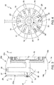
figure 4 is a rear view of the injection head offigure 3 ; -
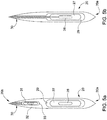
figure 5a is an enlarged cross section of a detail of the cross section of the injection head offigure 4 , cut along plane V-V offigure 4 ; -
figure 5b is an enlarged cross section of a detail of an injection head in accordance with a different embodiment of the present invention; -
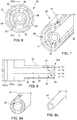
figure 6 is a rear view of a nozzle of the injection head offigure 3 ; -
figure 7 is a perspective view, partially cut along a longitudinal axial plane, of the nozzle offigure 6 ; -
figure 8 is a side view of the nozzle offigure 6 , cut along plane VIII-VIII offigure 6 ; -
figure 9a and 9b are perspective of respective components of the nozzle offigure 6 ; -
figure 10 is a rear view of an injection head of an injection nit in accordance to a different embodiment of the present invention; and -
figure 11 is a side view, cut along a longitudinal axial plane, of an injection head of an injection nit in accordance to another embodiment of the present invention. -
Figure 1 shows a simplified view of a gas turbine assembly, designated as whole withnumeral 1. Thegas turbine assembly 1 comprises acompressor section 2, acombustor assembly 3 and aturbine section 5. Thecompressor section 2 and theturbine section 5 extend along a main axis M. Thecombustor assembly 3 may be a single-stage combustor assembly or a sequential combustor assembly. In one embodiment, thecombustor assembly 3 comprises a plurality of sequential can combustors 7, circumferentially arranged about the main axis M. - The
compressor section 3 of thegas turbine assembly 1 provides a compressed airflow, which is added with fuel and burned in thecan combustors 7. The airflow delivered by thecompressor section 2 is supplied to thecombustor assembly 3 and to theturbine section 5 for the purpose of cooling. - In the
combustor assembly 3, the can combustors 7 are coupled to theturbine section 5 throughrespective transition ducts 8. - A portions of one of the
can combustors 7 is illustrated inFigure 2 . Thecan combustor 7 extends along a central axis A and comprises anouter shell 10, aliner 11 defining aflow path 12 for compressed air or hot gas and aninjection unit 13 configured to deliver a controlled amount of fuel into air or hot gas in the flow path. Thecan combustor 7 may be run on different kinds of fuel, depending on conditions. for example, thecan combustor 7 may use a gas fuel as a primary fuel and a liquid fuel as a secondary fuel. - The
injection unit 13 in turn comprises aninjection manifold 14, coupled to fuel feed lines (here not shown) for receiving the primary fuel and the secondary fuel, and aninjection head 15. Theinjection manifold 14 is coupled to theinjection head 15 through acompensator 17, which is configured to allow relative movements of theinjection manifold 14 and of theinjection head 15 in an axial direction and/or in a radial direction. Thecompensator 17 allows to damp vibrations and accommodate thermal expansion and may be in the form of bellows and/or an axial slider. - The
injection head 15, shown infigures 2 and3 , is arranged about the central axis A of thecan combustor 7 and comprises acentre body 18 with a plurality ofinjector fingers centre body 18 to the periphery of theflow path 12. In one embodiment, theinjector fingers flow path 12. In one embodiment, theinjection head 15 may be a monolithic body obtained by additive manufacturing techniques, such as Selective Laser Melting (SLM). The great advantage of the additive techniques reside in that they are extremely flexible and allow to produce complex objects incorporating a wide variety of features. The injection head can thus be built as a single body. This simplifies assembling of the injection unit, without limiting in any way functionality. In another embodiment, however, theinjection head 15 may be formed by assembled parts connected e.g. by a central fixing assembly extending along the central axis A. - A cooling
housing 21 and afuel plenum assembly 22 are provided in thecentre body 18 and both extend about the central axis A. - The cooling
housing 21 is provided on an upstream side by an outer casing of theinjection head 15 and defines an air plenum that at least partly encloses thefuel plenum assembly 22. - The
fuel plenum assembly 22 comprises aprimary fuel plenum 24 and asecondary fuel plenum 25, both of substantially annular shape about the central axis A. Thesecondary fuel plenum 25, which in one embodiment may be also cylindrical, is at least partly enclosed within theprimary fuel plenum 24. - The
injector fingers leading edges edges plenum assembly 22. In the embodiment offigures 2 and3 , theinjector fingers edges edges injector fingers - One of the injector fingers, here designated by numeral 20 (see also
figure 5a ), has a special design and provides also a function of inlet for primary and secondary fuel and for shielding air. Specifically, theinlet injector finger 20 comprises aprimary inlet line 27, fluidly coupled to theprimary fuel plenum 24, and asecondary inlet line 28, fluidly coupled to thesecondary fuel plenum 25 and at least in part enclosed within theprimary inlet line 27. Moreover, theinlet injector finger 20 comprises anair inlet 29, which at least in part encloses theprimary inlet line 27 and thesecondary inlet line 28 and is fluidly coupled to the coolingair housing 21. In the embodiment described, therefore, theprimary inlet line 27 and thesecondary inlet line 28 extend radially between the fuel plenum and the injection manifold. In this manner, theprimary inlet line 27 and thesecondary inlet line 28 are also aligned to theinjector finger 20 upstream in an axial direction, to the benefit of uniform airflow. This is not mandatory, however, and inlet lines may not be aligned to any injector finger. - At
respective trailing edges injector fingers injector finger figures 6 to 9a, 9b ) has a respective primary fuel line fluidly 31 coupled to theprimary fuel plenum 24, a respectivesecondary fuel line 32 fluidly coupled to thesecondary fuel plenum 25 and a respectiveshielding air line 33 fluidly coupled to the coolingair housing 21.Fuel nozzle 30 are oriented substantially parallel to the central axis A and discharge fuel in a downstream direction. In one embodiment, the fuel nozzle or nozzles of theinlet injector finger 20 may be directly coupled to theprimary inlet line 27 and/orsecondary inlet line 28, as shown infigure 5b . Moreover, in other embodiments not illustrated, some of thefuel nozzles 30 may be provided with theprimary fuel line 31 only. - The
primary fuel line 31, thesecondary fuel line 32 and the shieldingair line 33 are arranged coaxially, with the shieldingair line 33 enclosing theprimary fuel line 31 and theprimary fuel line 31 in turn enclosing thesecondary fuel line 32. Moreover, the primary fuel line fluidly 31, thesecondary fuel line 32 and the shieldingair line 33 extend substantially radially outward from thefuel plenum assembly 22 outside thenozzle 30 and substantially parallel to the central axis A inside thenozzle 30. Arrangement of theprimary fuel line 31, thesecondary fuel line 32 and the shieldingair line 33 does not need to be coaxial and mutual offset may be present to compensate for thermal expansion in accordance with design preferences. - The
secondary fuel line 32 tapers at adelivery end 30a of thenozzle 30, so that anannular space 35 is provided between theprimary fuel line 31 and the respectivesecondary fuel line 32. At thedelivery end 30a, theprimary fuel line 31 has throughopenings 37 that fluidly couple the shieldingair line 33 and theannular space 35. Theannular space 35 is open toward the outside, so that shielding air flowing through theopenings 37 is discharged downstream. Accordingly, a first shielding airflow F1 is delivered around theprimary fuel line 31 and a second shielding airflow F2 is delivered between theprimary fuel line 31 and the secondary fuel line 32 (figure 8 ). - Radial spacers 38 are provided between the
primary fuel line 31 and the shieldingair line 33 at thedelivery end 30a of thenozzle 30. The spacers 38 are integral with one of theprimary fuel line 31 and the shieldingair line 33 and axial sliding relative movement therebetween. - According to the embodiment illustrated in
figure 10 , an injection unit has substantially the structure already described except in that aninjection head 115 comprises a plurality ofinlet injection fingers 120 equally spaced in a circumferential direction about the central axis A. In the example offigure 10 , threeinjection fingers 120 at 120° with respect to one another are provided. Theinlet injection fingers 120 include respective nested shielding air lines, primary inlet lines and secondary inlet lines as already described (here not shown for the sake of simplicity). In embodiments not illustrated herein, theinlet injection fingers 120 may not be equally spaced in the circumferential direction. - According to the embodiment shown in
figure 11 , aninjection head 215 of aninjection unit 213 has substantially the structure of theinjection head 15 offigure 3 , except in that primary fuel, secondary fuel and cooling air are supplied axially. In this case, the primary inlet line 227 and thesecondary inlet line 228 feed axially directly into the fuel plenum assembly aninjection manifold 214 is connected to theinjection head 215 at the central axis and feeds directly into theprimary fuel plenum 224 and thesecondary fuel plenum 225. Air inlet is axially arranged as well and encloses in part primary inlet line 227 and thesecondary inlet line 228. - Inlet injector fingers with special design are not required in this case.
- Finally, it is evident that the described injection head may be subject to modifications and variations, without departing from the scope of the present invention, as defined in the appended claims.
Claims (15)
- An injection head for a gas turbine combustor, the injection head (15; 115; 215) comprising:a fuel plenum assembly (22) extending about the central axis (A) and including a primary fuel plenum (24; 224);a plurality of injector fingers (19, 20; 120) extending radially outward from the fuel plenum assembly (22) and each provided with at least a respective fuel nozzle (30);a fuel inlet (27, 28), fluidly coupled to the fuel plenum assembly (22);a cooling air housing, at least partly enclosing the fuel plenum assembly (22) and defining a cooling air plenum (21);wherein at least part of the fuel nozzles (30) have respective primary fuel lines (31) fluidly coupled to the primary fuel plenum (24; 224) and respective shielding air lines (33) fluidly coupled to the cooling air plenum (21).
- The injection head according to claim 1, wherein the fuel plenum assembly (22) includes a secondary fuel plenum (25; 225) extending about the central axis (A) and at least partly enclosed within the primary fuel plenum (24; 224), and wherein part of the fuel nozzles (30) have respective secondary fuel lines (32) at least partly enclosed within the respective primary fuel lines (31) and fluidly coupled to the secondary fuel plenum (25; 225).
- The injection head according to claim 2, wherein the fuel inlet (27, 28) comprises a primary inlet line (27), fluidly coupled to the primary fuel plenum (24; 224), and a secondary inlet line (28), fluidly coupled to the secondary fuel plenum (25; 225) and at least in part enclosed within the primary inlet line (27).
- The injection head according to claim 3, comprising an air inlet (29) at least in part enclosing the primary inlet line (27) and the secondary inlet line (28) and fluidly coupled to the cooling air plenum (21).
- The injection head according to claim 3 or 4, wherein the primary inlet line (27) and the secondary inlet line (28) extend radially between the fuel plenum assembly (22) and the injection manifold (14; 214).
- The injection head according to claim 5, wherein the primary inlet line (27) and the secondary inlet line (28) are aligned to a respective one of the injector fingers (19, 20; 120) upstream in an axial direction.
- The injection head according to claim 6, wherein the injector fingers (19, 20; 120) are in the form of streamlined bodies with respective leading edges (19a, 20a) and trailing edges (19b, 29b) extending radially outward from the fuel plenum assembly (22) and comprise at least an inlet injector finger (20) configured to be coupled to an injection manifold (14; 214), wherein the primary inlet line (27) and the secondary inlet line (28) are at least partially enclosed within the inlet injector finger (20).
- The injection head according to claim 7, comprising a plurality of primary inlet lines (27), fluidly coupled to the primary fuel plenum (24; 224), and of secondary inlet lines (28), fluidly coupled to the secondary fuel plenum (25; 225) at least in part enclosed within the respective primary inlet line (27), wherein the injector fingers (19, 20; 120) comprise a plurality of inlet injector fingers (19, 20; 120), and wherein the primary inlet lines (27) and the secondary inlet lines (28) are at least partially enclosed within respective inlet injector fingers (19, 20; 120) .
- The injection head according to claim 3 or 4, wherein the primary inlet line (27) and the secondary inlet line (28) feed axially into the fuel plenum assembly (22).
- The injection head according to any one of the preceding claims, wherein in each fuel nozzle (30) the respective shielding air line (33) encloses the respective primary fuel line (31) and secondary fuel line (32).
- The injection head according to claim 13, wherein the secondary fuel line (32) tapers at a delivery end (30a), whereby an annular space (35) is provided between the primary fuel line (31) and the respective secondary fuel line (32) at the delivery end (30a).
- The injection head according to claim 11, wherein the primary fuel line (31) has through openings (37) at the delivery end (30a), thereby fluidly coupling the shielding air line (33) and the annular space (35) between the primary fuel line (31) and the respective secondary fuel line (32) at the delivery end (30a).
- The injection head according to claim 11 or 12, comprising spacers (38) extending radially between the primary fuel line (31) and the respective shielding air line (33) at the delivery end (30a) and configured to allow the primary fuel line (31) to axially slide with respect to the shielding air line (33).
- The injection head according to any one of the foregoing claims, comprising a compensator (17) between the injection manifold (14; 214) and the injection head (15; 115; 215), the compensator (17) being configured to allow relative movements of the injection head (15; 115; 215) and of the injection manifold (14; 214) in an axial direction and/or in a radial direction.
- A gas turbine combustor, comprising at least an injection head (15; 115; 215) according to any one of the preceding claims and an injection manifold (14; 214) coupled to the injection head (15; 115; 215).
Applications Claiming Priority (1)
| Application Number | Priority Date | Filing Date | Title |
|---|---|---|---|
| RU2018146134A RU2769616C2 (en) | 2018-12-25 | 2018-12-25 | Injection head for the combustion chamber of a gas turbine |
Publications (2)
| Publication Number | Publication Date |
|---|---|
| EP3674608A1 true EP3674608A1 (en) | 2020-07-01 |
| EP3674608B1 EP3674608B1 (en) | 2022-12-07 |
Family
ID=69024198
Family Applications (1)
| Application Number | Title | Priority Date | Filing Date |
|---|---|---|---|
| EP19219662.4A Active EP3674608B1 (en) | 2018-12-25 | 2019-12-24 | Injection head for a gas turbine combustor |
Country Status (3)
| Country | Link |
|---|---|
| EP (1) | EP3674608B1 (en) |
| CN (1) | CN111380075B (en) |
| RU (1) | RU2769616C2 (en) |
Citations (6)
| Publication number | Priority date | Publication date | Assignee | Title |
|---|---|---|---|---|
| US20030121266A1 (en) * | 2001-12-21 | 2003-07-03 | Roberto Modi | Main liquid fuel injection device for a single combustion chamber, having a premixing chamber, of a gas turbine with low emission of pollutants |
| US20100180599A1 (en) * | 2009-01-21 | 2010-07-22 | Thomas Stephen R | Insertable Pre-Drilled Swirl Vane for Premixing Fuel Nozzle |
| US20140238036A1 (en) * | 2013-02-25 | 2014-08-28 | General Electric Company | Fuel/air mixing system for fuel nozzle |
| US20160146459A1 (en) * | 2014-11-26 | 2016-05-26 | General Electric Company | Premix fuel nozzle assembly |
| US20180100653A1 (en) * | 2016-10-08 | 2018-04-12 | Ansaldo Energia Switzerland AG | Dual fuel concentric nozzle for a gas turbine |
| US20180363551A1 (en) * | 2017-06-16 | 2018-12-20 | General Electric Company | System and method for combusting liquid fuel in a gas turbine combustor |
Family Cites Families (11)
| Publication number | Priority date | Publication date | Assignee | Title |
|---|---|---|---|---|
| DE3541987A1 (en) * | 1985-11-28 | 1987-06-04 | Sonvico Ag Ing Bureau | BURNERS FOR LIQUID AND / OR GASEOUS FUELS |
| US5363644A (en) * | 1989-12-21 | 1994-11-15 | Sundstrand Corporation | Annular combustor |
| US6389815B1 (en) * | 2000-09-08 | 2002-05-21 | General Electric Company | Fuel nozzle assembly for reduced exhaust emissions |
| US7762073B2 (en) * | 2006-03-01 | 2010-07-27 | General Electric Company | Pilot mixer for mixer assembly of a gas turbine engine combustor having a primary fuel injector and a plurality of secondary fuel injection ports |
| US8671691B2 (en) * | 2010-05-26 | 2014-03-18 | General Electric Company | Hybrid prefilming airblast, prevaporizing, lean-premixing dual-fuel nozzle for gas turbine combustor |
| RU2618801C2 (en) * | 2013-01-10 | 2017-05-11 | Дженерал Электрик Компани | Fuel nozzle, end fuel nozzle unit, and gas turbine |
| US9316155B2 (en) * | 2013-03-18 | 2016-04-19 | General Electric Company | System for providing fuel to a combustor |
| EP3076084B1 (en) * | 2015-03-30 | 2021-04-28 | Ansaldo Energia Switzerland AG | Fuel injector device |
| US9938903B2 (en) * | 2015-12-22 | 2018-04-10 | General Electric Company | Staged fuel and air injection in combustion systems of gas turbines |
| US10274201B2 (en) * | 2016-01-05 | 2019-04-30 | Solar Turbines Incorporated | Fuel injector with dual main fuel injection |
| US20170268786A1 (en) * | 2016-03-18 | 2017-09-21 | General Electric Company | Axially staged fuel injector assembly |
-
2018
- 2018-12-25 RU RU2018146134A patent/RU2769616C2/en active
-
2019
- 2019-12-24 EP EP19219662.4A patent/EP3674608B1/en active Active
- 2019-12-25 CN CN201911357666.1A patent/CN111380075B/en active Active
Patent Citations (6)
| Publication number | Priority date | Publication date | Assignee | Title |
|---|---|---|---|---|
| US20030121266A1 (en) * | 2001-12-21 | 2003-07-03 | Roberto Modi | Main liquid fuel injection device for a single combustion chamber, having a premixing chamber, of a gas turbine with low emission of pollutants |
| US20100180599A1 (en) * | 2009-01-21 | 2010-07-22 | Thomas Stephen R | Insertable Pre-Drilled Swirl Vane for Premixing Fuel Nozzle |
| US20140238036A1 (en) * | 2013-02-25 | 2014-08-28 | General Electric Company | Fuel/air mixing system for fuel nozzle |
| US20160146459A1 (en) * | 2014-11-26 | 2016-05-26 | General Electric Company | Premix fuel nozzle assembly |
| US20180100653A1 (en) * | 2016-10-08 | 2018-04-12 | Ansaldo Energia Switzerland AG | Dual fuel concentric nozzle for a gas turbine |
| US20180363551A1 (en) * | 2017-06-16 | 2018-12-20 | General Electric Company | System and method for combusting liquid fuel in a gas turbine combustor |
Also Published As
| Publication number | Publication date |
|---|---|
| EP3674608B1 (en) | 2022-12-07 |
| CN111380075B (en) | 2023-04-18 |
| RU2018146134A (en) | 2020-06-25 |
| RU2018146134A3 (en) | 2022-02-15 |
| RU2769616C2 (en) | 2022-04-04 |
| CN111380075A (en) | 2020-07-07 |
Similar Documents
| Publication | Publication Date | Title |
|---|---|---|
| EP3087322B1 (en) | Fuel nozzle with flexible support structures | |
| US11092084B2 (en) | Fuel delivery system for a gas turbine engine | |
| JP6134732B2 (en) | Multi-zone combustor | |
| US11629641B2 (en) | Fuel distribution manifold | |
| US10429070B2 (en) | Combustor assembly | |
| US10228136B2 (en) | Combustor assembly | |
| CN110494693B (en) | Single-cavity trapped vortex burner | |
| EP3060780B1 (en) | Fuel manifold assembly and method for assembly | |
| CN109140506B (en) | Nozzle assembly for dual fuel nozzle | |
| CN109386840B (en) | Scroll burners for gas turbine engines | |
| EP3211310B1 (en) | Combustor assembly | |
| CN108870444B (en) | Combustor assemblies for gas turbine engines | |
| EP3674608B1 (en) | Injection head for a gas turbine combustor | |
| JP7689839B2 (en) | Fuel nozzle having improved swirler vane configuration - Patents.com | |
| EP3943816B1 (en) | Combustor and fuel distribution manifold | |
| EP3674609B1 (en) | Modular injection head for a combustor of a gas turbine | |
| CN114483321B (en) | Integrated combustion nozzle with integral head | |
| US20130091849A1 (en) | Augmentor spray bar with tip support bushing |
Legal Events
| Date | Code | Title | Description |
|---|---|---|---|
| PUAI | Public reference made under article 153(3) epc to a published international application that has entered the european phase |
Free format text: ORIGINAL CODE: 0009012 |
|
| STAA | Information on the status of an ep patent application or granted ep patent |
Free format text: STATUS: THE APPLICATION HAS BEEN PUBLISHED |
|
| AK | Designated contracting states |
Kind code of ref document: A1 Designated state(s): AL AT BE BG CH CY CZ DE DK EE ES FI FR GB GR HR HU IE IS IT LI LT LU LV MC MK MT NL NO PL PT RO RS SE SI SK SM TR |
|
| AX | Request for extension of the european patent |
Extension state: BA ME |
|
| STAA | Information on the status of an ep patent application or granted ep patent |
Free format text: STATUS: REQUEST FOR EXAMINATION WAS MADE |
|
| 17P | Request for examination filed |
Effective date: 20201230 |
|
| RBV | Designated contracting states (corrected) |
Designated state(s): AL AT BE BG CH CY CZ DE DK EE ES FI FR GB GR HR HU IE IS IT LI LT LU LV MC MK MT NL NO PL PT RO RS SE SI SK SM TR |
|
| GRAP | Despatch of communication of intention to grant a patent |
Free format text: ORIGINAL CODE: EPIDOSNIGR1 |
|
| STAA | Information on the status of an ep patent application or granted ep patent |
Free format text: STATUS: GRANT OF PATENT IS INTENDED |
|
| INTG | Intention to grant announced |
Effective date: 20220629 |
|
| GRAS | Grant fee paid |
Free format text: ORIGINAL CODE: EPIDOSNIGR3 |
|
| GRAA | (expected) grant |
Free format text: ORIGINAL CODE: 0009210 |
|
| STAA | Information on the status of an ep patent application or granted ep patent |
Free format text: STATUS: THE PATENT HAS BEEN GRANTED |
|
| AK | Designated contracting states |
Kind code of ref document: B1 Designated state(s): AL AT BE BG CH CY CZ DE DK EE ES FI FR GB GR HR HU IE IS IT LI LT LU LV MC MK MT NL NO PL PT RO RS SE SI SK SM TR |
|
| REG | Reference to a national code |
Ref country code: GB Ref legal event code: FG4D |
|
| REG | Reference to a national code |
Ref country code: CH Ref legal event code: EP Ref country code: AT Ref legal event code: REF Ref document number: 1536515 Country of ref document: AT Kind code of ref document: T Effective date: 20221215 |
|
| REG | Reference to a national code |
Ref country code: DE Ref legal event code: R096 Ref document number: 602019022840 Country of ref document: DE |
|
| REG | Reference to a national code |
Ref country code: IE Ref legal event code: FG4D |
|
| REG | Reference to a national code |
Ref country code: LT Ref legal event code: MG9D |
|
| REG | Reference to a national code |
Ref country code: NL Ref legal event code: MP Effective date: 20221207 |
|
| PG25 | Lapsed in a contracting state [announced via postgrant information from national office to epo] |
Ref country code: SE Free format text: LAPSE BECAUSE OF FAILURE TO SUBMIT A TRANSLATION OF THE DESCRIPTION OR TO PAY THE FEE WITHIN THE PRESCRIBED TIME-LIMIT Effective date: 20221207 Ref country code: NO Free format text: LAPSE BECAUSE OF FAILURE TO SUBMIT A TRANSLATION OF THE DESCRIPTION OR TO PAY THE FEE WITHIN THE PRESCRIBED TIME-LIMIT Effective date: 20230307 Ref country code: LT Free format text: LAPSE BECAUSE OF FAILURE TO SUBMIT A TRANSLATION OF THE DESCRIPTION OR TO PAY THE FEE WITHIN THE PRESCRIBED TIME-LIMIT Effective date: 20221207 Ref country code: FI Free format text: LAPSE BECAUSE OF FAILURE TO SUBMIT A TRANSLATION OF THE DESCRIPTION OR TO PAY THE FEE WITHIN THE PRESCRIBED TIME-LIMIT Effective date: 20221207 Ref country code: ES Free format text: LAPSE BECAUSE OF FAILURE TO SUBMIT A TRANSLATION OF THE DESCRIPTION OR TO PAY THE FEE WITHIN THE PRESCRIBED TIME-LIMIT Effective date: 20221207 |
|
| REG | Reference to a national code |
Ref country code: AT Ref legal event code: MK05 Ref document number: 1536515 Country of ref document: AT Kind code of ref document: T Effective date: 20221207 |
|
| PG25 | Lapsed in a contracting state [announced via postgrant information from national office to epo] |
Ref country code: RS Free format text: LAPSE BECAUSE OF FAILURE TO SUBMIT A TRANSLATION OF THE DESCRIPTION OR TO PAY THE FEE WITHIN THE PRESCRIBED TIME-LIMIT Effective date: 20221207 Ref country code: PL Free format text: LAPSE BECAUSE OF FAILURE TO SUBMIT A TRANSLATION OF THE DESCRIPTION OR TO PAY THE FEE WITHIN THE PRESCRIBED TIME-LIMIT Effective date: 20221207 Ref country code: LV Free format text: LAPSE BECAUSE OF FAILURE TO SUBMIT A TRANSLATION OF THE DESCRIPTION OR TO PAY THE FEE WITHIN THE PRESCRIBED TIME-LIMIT Effective date: 20221207 Ref country code: HR Free format text: LAPSE BECAUSE OF FAILURE TO SUBMIT A TRANSLATION OF THE DESCRIPTION OR TO PAY THE FEE WITHIN THE PRESCRIBED TIME-LIMIT Effective date: 20221207 Ref country code: GR Free format text: LAPSE BECAUSE OF FAILURE TO SUBMIT A TRANSLATION OF THE DESCRIPTION OR TO PAY THE FEE WITHIN THE PRESCRIBED TIME-LIMIT Effective date: 20230308 |
|
| PG25 | Lapsed in a contracting state [announced via postgrant information from national office to epo] |
Ref country code: NL Free format text: LAPSE BECAUSE OF FAILURE TO SUBMIT A TRANSLATION OF THE DESCRIPTION OR TO PAY THE FEE WITHIN THE PRESCRIBED TIME-LIMIT Effective date: 20221207 |
|
| PG25 | Lapsed in a contracting state [announced via postgrant information from national office to epo] |
Ref country code: SM Free format text: LAPSE BECAUSE OF FAILURE TO SUBMIT A TRANSLATION OF THE DESCRIPTION OR TO PAY THE FEE WITHIN THE PRESCRIBED TIME-LIMIT Effective date: 20221207 Ref country code: RO Free format text: LAPSE BECAUSE OF FAILURE TO SUBMIT A TRANSLATION OF THE DESCRIPTION OR TO PAY THE FEE WITHIN THE PRESCRIBED TIME-LIMIT Effective date: 20221207 Ref country code: PT Free format text: LAPSE BECAUSE OF FAILURE TO SUBMIT A TRANSLATION OF THE DESCRIPTION OR TO PAY THE FEE WITHIN THE PRESCRIBED TIME-LIMIT Effective date: 20230410 Ref country code: EE Free format text: LAPSE BECAUSE OF FAILURE TO SUBMIT A TRANSLATION OF THE DESCRIPTION OR TO PAY THE FEE WITHIN THE PRESCRIBED TIME-LIMIT Effective date: 20221207 Ref country code: CZ Free format text: LAPSE BECAUSE OF FAILURE TO SUBMIT A TRANSLATION OF THE DESCRIPTION OR TO PAY THE FEE WITHIN THE PRESCRIBED TIME-LIMIT Effective date: 20221207 Ref country code: AT Free format text: LAPSE BECAUSE OF FAILURE TO SUBMIT A TRANSLATION OF THE DESCRIPTION OR TO PAY THE FEE WITHIN THE PRESCRIBED TIME-LIMIT Effective date: 20221207 Ref country code: IT Free format text: LAPSE BECAUSE OF NON-PAYMENT OF DUE FEES Effective date: 20221224 |
|
| REG | Reference to a national code |
Ref country code: CH Ref legal event code: PL |
|
| REG | Reference to a national code |
Ref country code: BE Ref legal event code: MM Effective date: 20221231 |
|
| PG25 | Lapsed in a contracting state [announced via postgrant information from national office to epo] |
Ref country code: SK Free format text: LAPSE BECAUSE OF FAILURE TO SUBMIT A TRANSLATION OF THE DESCRIPTION OR TO PAY THE FEE WITHIN THE PRESCRIBED TIME-LIMIT Effective date: 20221207 Ref country code: LU Free format text: LAPSE BECAUSE OF NON-PAYMENT OF DUE FEES Effective date: 20221224 Ref country code: IS Free format text: LAPSE BECAUSE OF FAILURE TO SUBMIT A TRANSLATION OF THE DESCRIPTION OR TO PAY THE FEE WITHIN THE PRESCRIBED TIME-LIMIT Effective date: 20230407 Ref country code: AL Free format text: LAPSE BECAUSE OF FAILURE TO SUBMIT A TRANSLATION OF THE DESCRIPTION OR TO PAY THE FEE WITHIN THE PRESCRIBED TIME-LIMIT Effective date: 20221207 |
|
| REG | Reference to a national code |
Ref country code: DE Ref legal event code: R097 Ref document number: 602019022840 Country of ref document: DE |
|
| PG25 | Lapsed in a contracting state [announced via postgrant information from national office to epo] |
Ref country code: MC Free format text: LAPSE BECAUSE OF FAILURE TO SUBMIT A TRANSLATION OF THE DESCRIPTION OR TO PAY THE FEE WITHIN THE PRESCRIBED TIME-LIMIT Effective date: 20221207 |
|
| PLBE | No opposition filed within time limit |
Free format text: ORIGINAL CODE: 0009261 |
|
| STAA | Information on the status of an ep patent application or granted ep patent |
Free format text: STATUS: NO OPPOSITION FILED WITHIN TIME LIMIT |
|
| PG25 | Lapsed in a contracting state [announced via postgrant information from national office to epo] |
Ref country code: LI Free format text: LAPSE BECAUSE OF NON-PAYMENT OF DUE FEES Effective date: 20221231 Ref country code: IE Free format text: LAPSE BECAUSE OF NON-PAYMENT OF DUE FEES Effective date: 20221224 Ref country code: DK Free format text: LAPSE BECAUSE OF FAILURE TO SUBMIT A TRANSLATION OF THE DESCRIPTION OR TO PAY THE FEE WITHIN THE PRESCRIBED TIME-LIMIT Effective date: 20221207 Ref country code: CH Free format text: LAPSE BECAUSE OF NON-PAYMENT OF DUE FEES Effective date: 20221231 |
|
| 26N | No opposition filed |
Effective date: 20230908 |
|
| PG25 | Lapsed in a contracting state [announced via postgrant information from national office to epo] |
Ref country code: SI Free format text: LAPSE BECAUSE OF FAILURE TO SUBMIT A TRANSLATION OF THE DESCRIPTION OR TO PAY THE FEE WITHIN THE PRESCRIBED TIME-LIMIT Effective date: 20221207 Ref country code: BE Free format text: LAPSE BECAUSE OF NON-PAYMENT OF DUE FEES Effective date: 20221231 |
|
| PG25 | Lapsed in a contracting state [announced via postgrant information from national office to epo] |
Ref country code: IT Free format text: LAPSE BECAUSE OF NON-PAYMENT OF DUE FEES Effective date: 20221224 Ref country code: FR Free format text: LAPSE BECAUSE OF NON-PAYMENT OF DUE FEES Effective date: 20230207 |
|
| PGRI | Patent reinstated in contracting state [announced from national office to epo] |
Ref country code: IT Effective date: 20221231 |
|
| PG25 | Lapsed in a contracting state [announced via postgrant information from national office to epo] |
Ref country code: HU Free format text: LAPSE BECAUSE OF FAILURE TO SUBMIT A TRANSLATION OF THE DESCRIPTION OR TO PAY THE FEE WITHIN THE PRESCRIBED TIME-LIMIT; INVALID AB INITIO Effective date: 20191224 |
|
| PG25 | Lapsed in a contracting state [announced via postgrant information from national office to epo] |
Ref country code: CY Free format text: LAPSE BECAUSE OF FAILURE TO SUBMIT A TRANSLATION OF THE DESCRIPTION OR TO PAY THE FEE WITHIN THE PRESCRIBED TIME-LIMIT Effective date: 20221207 |
|
| PG25 | Lapsed in a contracting state [announced via postgrant information from national office to epo] |
Ref country code: MK Free format text: LAPSE BECAUSE OF FAILURE TO SUBMIT A TRANSLATION OF THE DESCRIPTION OR TO PAY THE FEE WITHIN THE PRESCRIBED TIME-LIMIT Effective date: 20221207 |
|
| P01 | Opt-out of the competence of the unified patent court (upc) registered |
Effective date: 20240430 |
|
| PG25 | Lapsed in a contracting state [announced via postgrant information from national office to epo] |
Ref country code: BG Free format text: LAPSE BECAUSE OF FAILURE TO SUBMIT A TRANSLATION OF THE DESCRIPTION OR TO PAY THE FEE WITHIN THE PRESCRIBED TIME-LIMIT Effective date: 20221207 |
|
| PG25 | Lapsed in a contracting state [announced via postgrant information from national office to epo] |
Ref country code: MT Free format text: LAPSE BECAUSE OF FAILURE TO SUBMIT A TRANSLATION OF THE DESCRIPTION OR TO PAY THE FEE WITHIN THE PRESCRIBED TIME-LIMIT Effective date: 20221207 |
|
| PG25 | Lapsed in a contracting state [announced via postgrant information from national office to epo] |
Ref country code: TR Free format text: LAPSE BECAUSE OF FAILURE TO SUBMIT A TRANSLATION OF THE DESCRIPTION OR TO PAY THE FEE WITHIN THE PRESCRIBED TIME-LIMIT Effective date: 20221207 |
|
| PGFP | Annual fee paid to national office [announced via postgrant information from national office to epo] |
Ref country code: GB Payment date: 20251218 Year of fee payment: 7 |
|
| PGFP | Annual fee paid to national office [announced via postgrant information from national office to epo] |
Ref country code: DE Payment date: 20251222 Year of fee payment: 7 |
|
| PGFP | Annual fee paid to national office [announced via postgrant information from national office to epo] |
Ref country code: IT Payment date: 20251231 Year of fee payment: 7 |