EP3674599B1 - Lamp - Google Patents
Lamp Download PDFInfo
- Publication number
- EP3674599B1 EP3674599B1 EP19214255.2A EP19214255A EP3674599B1 EP 3674599 B1 EP3674599 B1 EP 3674599B1 EP 19214255 A EP19214255 A EP 19214255A EP 3674599 B1 EP3674599 B1 EP 3674599B1
- Authority
- EP
- European Patent Office
- Prior art keywords
- lamp body
- lamp
- assembly
- light
- positioning frame
- Prior art date
- Legal status (The legal status is an assumption and is not a legal conclusion. Google has not performed a legal analysis and makes no representation as to the accuracy of the status listed.)
- Active
Links
Images


Classifications
-
- F—MECHANICAL ENGINEERING; LIGHTING; HEATING; WEAPONS; BLASTING
- F21—LIGHTING
- F21S—NON-PORTABLE LIGHTING DEVICES; SYSTEMS THEREOF; VEHICLE LIGHTING DEVICES SPECIALLY ADAPTED FOR VEHICLE EXTERIORS
- F21S8/00—Lighting devices intended for fixed installation
- F21S8/02—Lighting devices intended for fixed installation of recess-mounted type, e.g. downlighters
-
- F—MECHANICAL ENGINEERING; LIGHTING; HEATING; WEAPONS; BLASTING
- F21—LIGHTING
- F21V—FUNCTIONAL FEATURES OR DETAILS OF LIGHTING DEVICES OR SYSTEMS THEREOF; STRUCTURAL COMBINATIONS OF LIGHTING DEVICES WITH OTHER ARTICLES, NOT OTHERWISE PROVIDED FOR
- F21V17/00—Fastening of component parts of lighting devices, e.g. shades, globes, refractors, reflectors, filters, screens, grids or protective cages
- F21V17/02—Fastening of component parts of lighting devices, e.g. shades, globes, refractors, reflectors, filters, screens, grids or protective cages with provision for adjustment
-
- F—MECHANICAL ENGINEERING; LIGHTING; HEATING; WEAPONS; BLASTING
- F21—LIGHTING
- F21V—FUNCTIONAL FEATURES OR DETAILS OF LIGHTING DEVICES OR SYSTEMS THEREOF; STRUCTURAL COMBINATIONS OF LIGHTING DEVICES WITH OTHER ARTICLES, NOT OTHERWISE PROVIDED FOR
- F21V17/00—Fastening of component parts of lighting devices, e.g. shades, globes, refractors, reflectors, filters, screens, grids or protective cages
- F21V17/10—Fastening of component parts of lighting devices, e.g. shades, globes, refractors, reflectors, filters, screens, grids or protective cages characterised by specific fastening means or way of fastening
-
- F—MECHANICAL ENGINEERING; LIGHTING; HEATING; WEAPONS; BLASTING
- F21—LIGHTING
- F21V—FUNCTIONAL FEATURES OR DETAILS OF LIGHTING DEVICES OR SYSTEMS THEREOF; STRUCTURAL COMBINATIONS OF LIGHTING DEVICES WITH OTHER ARTICLES, NOT OTHERWISE PROVIDED FOR
- F21V17/00—Fastening of component parts of lighting devices, e.g. shades, globes, refractors, reflectors, filters, screens, grids or protective cages
- F21V17/10—Fastening of component parts of lighting devices, e.g. shades, globes, refractors, reflectors, filters, screens, grids or protective cages characterised by specific fastening means or way of fastening
- F21V17/12—Fastening of component parts of lighting devices, e.g. shades, globes, refractors, reflectors, filters, screens, grids or protective cages characterised by specific fastening means or way of fastening by screwing
-
- F—MECHANICAL ENGINEERING; LIGHTING; HEATING; WEAPONS; BLASTING
- F21—LIGHTING
- F21V—FUNCTIONAL FEATURES OR DETAILS OF LIGHTING DEVICES OR SYSTEMS THEREOF; STRUCTURAL COMBINATIONS OF LIGHTING DEVICES WITH OTHER ARTICLES, NOT OTHERWISE PROVIDED FOR
- F21V17/00—Fastening of component parts of lighting devices, e.g. shades, globes, refractors, reflectors, filters, screens, grids or protective cages
- F21V17/10—Fastening of component parts of lighting devices, e.g. shades, globes, refractors, reflectors, filters, screens, grids or protective cages characterised by specific fastening means or way of fastening
- F21V17/16—Fastening of component parts of lighting devices, e.g. shades, globes, refractors, reflectors, filters, screens, grids or protective cages characterised by specific fastening means or way of fastening by deformation of parts; Snap action mounting
-
- F—MECHANICAL ENGINEERING; LIGHTING; HEATING; WEAPONS; BLASTING
- F21—LIGHTING
- F21V—FUNCTIONAL FEATURES OR DETAILS OF LIGHTING DEVICES OR SYSTEMS THEREOF; STRUCTURAL COMBINATIONS OF LIGHTING DEVICES WITH OTHER ARTICLES, NOT OTHERWISE PROVIDED FOR
- F21V21/00—Supporting, suspending, or attaching arrangements for lighting devices; Hand grips
-
- F—MECHANICAL ENGINEERING; LIGHTING; HEATING; WEAPONS; BLASTING
- F21—LIGHTING
- F21V—FUNCTIONAL FEATURES OR DETAILS OF LIGHTING DEVICES OR SYSTEMS THEREOF; STRUCTURAL COMBINATIONS OF LIGHTING DEVICES WITH OTHER ARTICLES, NOT OTHERWISE PROVIDED FOR
- F21V21/00—Supporting, suspending, or attaching arrangements for lighting devices; Hand grips
- F21V21/02—Wall, ceiling, or floor bases; Fixing pendants or arms to the bases
- F21V21/04—Recessed bases
-
- F—MECHANICAL ENGINEERING; LIGHTING; HEATING; WEAPONS; BLASTING
- F21—LIGHTING
- F21V—FUNCTIONAL FEATURES OR DETAILS OF LIGHTING DEVICES OR SYSTEMS THEREOF; STRUCTURAL COMBINATIONS OF LIGHTING DEVICES WITH OTHER ARTICLES, NOT OTHERWISE PROVIDED FOR
- F21V21/00—Supporting, suspending, or attaching arrangements for lighting devices; Hand grips
- F21V21/14—Adjustable mountings
-
- F—MECHANICAL ENGINEERING; LIGHTING; HEATING; WEAPONS; BLASTING
- F21—LIGHTING
- F21V—FUNCTIONAL FEATURES OR DETAILS OF LIGHTING DEVICES OR SYSTEMS THEREOF; STRUCTURAL COMBINATIONS OF LIGHTING DEVICES WITH OTHER ARTICLES, NOT OTHERWISE PROVIDED FOR
- F21V21/00—Supporting, suspending, or attaching arrangements for lighting devices; Hand grips
- F21V21/14—Adjustable mountings
- F21V21/30—Pivoted housings or frames
-
- F—MECHANICAL ENGINEERING; LIGHTING; HEATING; WEAPONS; BLASTING
- F21—LIGHTING
- F21S—NON-PORTABLE LIGHTING DEVICES; SYSTEMS THEREOF; VEHICLE LIGHTING DEVICES SPECIALLY ADAPTED FOR VEHICLE EXTERIORS
- F21S8/00—Lighting devices intended for fixed installation
- F21S8/02—Lighting devices intended for fixed installation of recess-mounted type, e.g. downlighters
- F21S8/026—Lighting devices intended for fixed installation of recess-mounted type, e.g. downlighters intended to be recessed in a ceiling or like overhead structure, e.g. suspended ceiling
-
- F—MECHANICAL ENGINEERING; LIGHTING; HEATING; WEAPONS; BLASTING
- F21—LIGHTING
- F21V—FUNCTIONAL FEATURES OR DETAILS OF LIGHTING DEVICES OR SYSTEMS THEREOF; STRUCTURAL COMBINATIONS OF LIGHTING DEVICES WITH OTHER ARTICLES, NOT OTHERWISE PROVIDED FOR
- F21V17/00—Fastening of component parts of lighting devices, e.g. shades, globes, refractors, reflectors, filters, screens, grids or protective cages
- F21V17/10—Fastening of component parts of lighting devices, e.g. shades, globes, refractors, reflectors, filters, screens, grids or protective cages characterised by specific fastening means or way of fastening
- F21V17/14—Bayonet-type fastening
-
- F—MECHANICAL ENGINEERING; LIGHTING; HEATING; WEAPONS; BLASTING
- F21—LIGHTING
- F21Y—INDEXING SCHEME ASSOCIATED WITH SUBCLASSES F21K, F21L, F21S and F21V, RELATING TO THE FORM OR THE KIND OF THE LIGHT SOURCES OR OF THE COLOUR OF THE LIGHT EMITTED
- F21Y2115/00—Light-generating elements of semiconductor light sources
- F21Y2115/10—Light-emitting diodes [LED]
Definitions
- the present invention relates to lighting field, with particular emphasis on a lamp.
- the lamp In the assembly, the lamp generally needs to be fixed by additional components such as a face frame, that is, the lamp body assembly is fixedly connected with the face frame to form a complete lamp.
- the lamp body component such as the LED light source breaks down
- the entire lamp needs to be disassembled, the maintenance is inconvenient, and the cost is increased.
- KR 2009 0110008 A , EP 1 462 710 A1 , US 2012/113654 A1 , KR 200 462 751 Y1 disclose different embodiments of LED lamp spots.
- the fixed structure causes a lamp to correspond to a lens or a filter.
- the entire lamp has to be replaced, resulting in waste of resources, which limits the scope of application of the lamp and further increases costs.
- an object of the present invention is to provide a lamp with simple structure, detachable, convenient maintenance, and low cost.
- the invention relates to a lamp, comprising a lamp body assembly, a positioning frame assembly surrounding the periphery of the lamp body assembly for assembling the lamp body assembly to the fixture, wherein:
- the lamp body assembly is detachably assembled with the positioning frame assembly.
- the inner wall of the positioning frame assembly is provided with a groove formed along the circumferential direction of the positioning frame assembly, and the lamp body assembly is provided with a marble on the periphery that can be chimed with the groove to realize the connection between the lamp body assembly and the positioning frame assembly, and the marble drives the lamp body assembly to slide in the groove.
- the lamp body assembly includes a lamp body and advantageously a fixing frame disposed on the outer wall of the lamp body and fixedly connected to the lamp body, and the marble is positioned on the fixing frame.
- the lamp body includes a light-emitting cylinder, a light source located at a rear end of the light-emitting cylinder, and a lens assembly detachable at a front end of the light-emitting cylinder.
- the lens assembly includes a lens located at the illumination end of the light source and connected with the light source main board, a decorative ring disposed at the light emitting end of the lens and matched with the inner wall of the light-emitting cylinder, and a detachable filter mounted on the decorative ring.
- the inner wall of the decorative ring is provided with a carrying platform that is in contact with the light incident surface of the filter, and at least two bumps disposed above the carrying platform and in contact with the edge of the light exit surface of the filter to prevent the filter from falling off.
- the side wall of the decorative ring above the carrying platform is separated by two slits facing the light incident end of the light-emitting cylinder to form an elastic wall, and one of the at least two bumps is located on the elastic wall.
- the positioning frame assembly is a ring like positioning frame, the opposite sides of the positioning frame assembly are provided with a pair of lugs for clamping.
- the invention has the advantages that the positioning frame assembly and the lamp body assembly are detachably connected, and when the lamp body assembly is damaged, the lamp body assembly can be directly removed for maintenance, and the maintenance is convenient; the sliding fit between the marble and the groove simplifies the assembly structure; the lens assembly is arranged in a detachable structure, and the filter is detachably disposed on the decorative ring, so that the lens or the filter can be replaced according to actual needs, thereby meeting different illumination effects, and the structure can be combined with the sliding setting of the positioning frame assembly and the lamp body assembly to further ensure the changing requirements of the illumination angle and realize different illumination requirements.
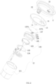
- FIG.1-3 is a schematic structural view of a preferred embodiment of the lamp of the present application.
- the lamp comprises a lamp body assembly 1 and a positioning frame assembly 2 surrounding the outer periphery of the lamp body assembly 1 for assembling the lamp body assembly 1 to a fixture.
- the lamp body assembly 1 and the positioning frame assembly 2 are detachably assembled.
- this kind of lamp is commonly used in spotlight, down light, ceiling lamp, etc., but this kind of structure is not excluded for lamps of other uses.
- the specific use of the lamps is not the focus of the protection of the present application, so it is not elaborated here.
- the positioning frame assembly serves as a connection medium between the lamp body assembly and the fixture surface, and the lamp body assembly is often fixed to the fixture surface by the positioning frame assembly.
- the existing positioning frame assembly and the lamp body assembly are generally welded or integrally formed.
- the positioning frame assembly is fixed by screw driven by the electric drill. If this operation is repeated many times, it will cause inconvenience in disassembly. At the same time, the mounting hole on the fixture will become larger due to repeated repetition of such operations, which will affect the fastness of assembly.
- the positioning frame assembly and the lamp body assembly are designed to be detachably assembled, and in the event of a failure of the light source or the like, only the lamp body assembly needs to be removed for maintenance, which reduces maintenance troubles.
- the inner wall of the positioning frame assembly 2 is provided with a groove 21 formed along the circumferential direction of the positioning frame assembly 2, and the lamp body assembly 1 is provided with a marble 11 on the periphery that can be chimed with the groove 21 to realize the connection between the lamp body assembly 1 and the positioning frame assembly 2, and the marble 11 can drive the lamp body assembly 1 to slide in the groove 21.
- the structure is simple in design, reduces the production cost, and is convenient to install.
- the entire lamp body assembly 1 can be pulled out from the groove 21, so that the marble 11 is separated from the groove 21, and only the lamp body assembly 1 needs to be repaired, reducing the maintenance cost.
- the combination of marbles and grooves enables the lamp body assembly to have the rotating function, good hand feeling, even pull strength, which can effectively prevent the lamp body assembly from being damaged due to uneven force when pulling out from the grooves.
- the lamp body assembly 1 includes a lamp body 12 and a fixing frame 13 disposed on the outer wall of the lamp body 12 and fixedly connected to the lamp body 12.
- the marble 11 is positioned on the fixing frame 13.
- the shape of the fixing frame 13 can be determined according to the actual situation, as long as the marble 11 is positioned on the fixing frame 13 and can cooperate with the groove 21.
- the lamp body 12 rotates within the positioning frame assembly 2. It is conceivable that when the light emitted from the lamp body 12 is different, the lamp body 12 can be rotated within the positioning frame assembly 2 to achieve different illumination effects, which will be explained below.
- the fixing frame 13 is fixedly connected to the outer wall of the lamp body 12 by the rivet 14 in this application, as shown in FIG. 2 and 3 , the fixing frame 13 is a fixing ring disposed around the periphery of the lamp body 12, and the positioning frame assembly 2 is ring like positioning frame.
- the lamp body 12 includes a light-emitting cylinder 121, a light source 122 located at the rear end of the light-emitting cylinder 121, and a lens assembly 123 detachable at the front end of the light-emitting cylinder 121.
- the lens assembly 123 comprises a lens 125 located at the illumination end of the light source 122 and connected with the light source main board 124 through screws, a decorative ring 126 fixed at the light emitting end of the lens 125 and matched with the inner wall of the light-emitting cylinder 121, and a detachable filter 127 mounted on the decorative ring 126.
- the inner wall of the decorative ring 126 is provided with a carrying platform 128 that is in contact with the light incident surface of the filter 127, and at least two bumps 129 disposed above the carrying platform 128 and in contact with the edge of the light exit surface of the filter 127 to prevent the filter 127 from falling off.
- the side wall of the decorative ring 126 above the carrying platform 128 is separated by two slits 130 facing the light incident end of the light-emitting cylinder 121 to form an elastic wall 131, and one of the at least two bumps 129 is located on the elastic wall 131.
- the light exit surface of the filter 127 is provided with a protrusion 127A for the finger to grip.
- the filter 127 is designed as a detachable connection that can be achieved by simply replacing the filter with the required thickness when the user needs different lighting effects, without replacing the entire lamp body or even the entire lamp.
- the detachable connection of the lens assembly also makes it easy for the user to replace the lens and filter together and install other suitable lens assembly as required, thereby meeting the lighting requirements of different angles and effects, which not only reduces the stock of lamp accessories, reduces the inventory and cost pressure, and at the same time, combined with the function that the lamp body assembly 1 can rotate within the positioning frame assembly 2 with the cooperation of marble 11 and groove 21,but also expand the illumination angle adjustment range, thereby better realizing different illumination requirements, so as to achieve better illumination effect.
- the specific installation and fixation mode of the replaced lens assembly is similar to the above, which is not described here.
- the opposite sides of the positioning frame assembly 2 in the present application are further provided with a pair of lugs 22 for clamping, which can be clamped and fixed with the fixture, such as when the lamp is a ceiling light, generally the hole is opened in the ceiling.
- the lug 22 is used to clamp the ceiling through the hole to secure the entire lamp.
Landscapes
- Engineering & Computer Science (AREA)
- General Engineering & Computer Science (AREA)
- Fastening Of Light Sources Or Lamp Holders (AREA)
- Securing Globes, Refractors, Reflectors Or The Like (AREA)
- Non-Portable Lighting Devices Or Systems Thereof (AREA)
Description
- This application claims priority to a Chinese Patent Application No.
CN 201811596020.4, filed on December 25, 2018 - The present invention relates to lighting field, with particular emphasis on a lamp.
- In the assembly, the lamp generally needs to be fixed by additional components such as a face frame, that is, the lamp body assembly is fixedly connected with the face frame to form a complete lamp. In this fixed structure, when the lamp body component such as the LED light source breaks down, the entire lamp needs to be disassembled, the maintenance is inconvenient, and the cost is increased.
KR 2009 0110008 A EP 1 462 710 A1 ,US 2012/113654 A1 ,KR 200 462 751 Y1 - Moreover, the fixed structure causes a lamp to correspond to a lens or a filter. To achieve different illumination effects and obtain different spots, the entire lamp has to be replaced, resulting in waste of resources, which limits the scope of application of the lamp and further increases costs.
- In view of the above problems, an object of the present invention is to provide a lamp with simple structure, detachable, convenient maintenance, and low cost.
- it is also an object of the present invention to provide a lamp capable of providing a plurality of illumination effects.
- In particular, the invention relates to a lamp, comprising a lamp body assembly, a positioning frame assembly surrounding the periphery of the lamp body assembly for assembling the lamp body assembly to the fixture, wherein:
- the lamp body assembly is detachably assembled with the positioning frame assembly.
- The inner wall of the positioning frame assembly is provided with a groove formed along the circumferential direction of the positioning frame assembly, and the lamp body assembly is provided with a marble on the periphery that can be chimed with the groove to realize the connection between the lamp body assembly and the positioning frame assembly, and the marble drives the lamp body assembly to slide in the groove.
- The lamp body assembly includes a lamp body and advantageously a fixing frame disposed on the outer wall of the lamp body and fixedly connected to the lamp body, and the marble is positioned on the fixing frame.
- The lamp body includes a light-emitting cylinder, a light source located at a rear end of the light-emitting cylinder, and a lens assembly detachable at a front end of the light-emitting cylinder.
- The lens assembly includes a lens located at the illumination end of the light source and connected with the light source main board, a decorative ring disposed at the light emitting end of the lens and matched with the inner wall of the light-emitting cylinder, and a detachable filter mounted on the decorative ring.
- The inner wall of the decorative ring is provided with a carrying platform that is in contact with the light incident surface of the filter, and at least two bumps disposed above the carrying platform and in contact with the edge of the light exit surface of the filter to prevent the filter from falling off.
- Advantageously, the side wall of the decorative ring above the carrying platform is separated by two slits facing the light incident end of the light-emitting cylinder to form an elastic wall, and one of the at least two bumps is located on the elastic wall.
- advantageously, the fixing frame is fixedly connected to the outer wall of the lamp body by a rivet.
- advantageously, the fixing frame is a fixing ring disposed around the periphery of the lamp body.
- Advantageously, the positioning frame assembly is a ring like positioning frame, the opposite sides of the positioning frame assembly are provided with a pair of lugs for clamping.
- Compared with the prior art, the invention has the advantages that the positioning frame assembly and the lamp body assembly are detachably connected, and when the lamp body assembly is damaged, the lamp body assembly can be directly removed for maintenance, and the maintenance is convenient; the sliding fit between the marble and the groove simplifies the assembly structure; the lens assembly is arranged in a detachable structure, and the filter is detachably disposed on the decorative ring, so that the lens or the filter can be replaced according to actual needs, thereby meeting different illumination effects, and the structure can be combined with the sliding setting of the positioning frame assembly and the lamp body assembly to further ensure the changing requirements of the illumination angle and realize different illumination requirements.
-
-
FIG. 1 is a schematic structural view of a lamp of the present application. -
FIG. 2 is an exploded view of the lamp of the present application. -
FIG. 3 is a cross-sectional view of the lamp of the present application. - the present application is illustrated by way of the following detailed description based on of the accompanying drawings. It should be noted that illustration to the embodiment in this application is not intended to limit the invention. The embodiments of the present invention are described in detail below, and the examples of the embodiments are illustrated in the drawings, wherein the same or similar reference numerals are used to refer to the same or similar elements or elements having the same or similar functions. The embodiments described below with reference to the accompanying drawings are intended to be illustrative of the invention and are not to be construed as limiting.
-
FIG.1-3 is a schematic structural view of a preferred embodiment of the lamp of the present application. The lamp comprises alamp body assembly 1 and apositioning frame assembly 2 surrounding the outer periphery of thelamp body assembly 1 for assembling thelamp body assembly 1 to a fixture. Thelamp body assembly 1 and thepositioning frame assembly 2 are detachably assembled. Generally, this kind of lamp is commonly used in spotlight, down light, ceiling lamp, etc., but this kind of structure is not excluded for lamps of other uses. At the same time, the specific use of the lamps is not the focus of the protection of the present application, so it is not elaborated here. - As is well known, the positioning frame assembly serves as a connection medium between the lamp body assembly and the fixture surface, and the lamp body assembly is often fixed to the fixture surface by the positioning frame assembly. The existing positioning frame assembly and the lamp body assembly are generally welded or integrally formed. When the light source or other internal components in the lamp break down, it is necessary to remove the lamp from the fixture surface as a whole. In many cases, the positioning frame assembly is fixed by screw driven by the electric drill. If this operation is repeated many times, it will cause inconvenience in disassembly. At the same time, the mounting hole on the fixture will become larger due to repeated repetition of such operations, which will affect the fastness of assembly. In the present application, the positioning frame assembly and the lamp body assembly are designed to be detachably assembled, and in the event of a failure of the light source or the like, only the lamp body assembly needs to be removed for maintenance, which reduces maintenance troubles.
- In this embodiment, referring to
FIG. 2 , the inner wall of thepositioning frame assembly 2 is provided with agroove 21 formed along the circumferential direction of thepositioning frame assembly 2, and thelamp body assembly 1 is provided with amarble 11 on the periphery that can be chimed with thegroove 21 to realize the connection between thelamp body assembly 1 and thepositioning frame assembly 2, and themarble 11 can drive thelamp body assembly 1 to slide in thegroove 21. The structure is simple in design, reduces the production cost, and is convenient to install. When the light source in the lamp body assembly, namely the LED lamp, is broken, the entirelamp body assembly 1 can be pulled out from thegroove 21, so that themarble 11 is separated from thegroove 21, and only thelamp body assembly 1 needs to be repaired, reducing the maintenance cost. Moreover, the combination of marbles and grooves enables the lamp body assembly to have the rotating function, good hand feeling, even pull strength, which can effectively prevent the lamp body assembly from being damaged due to uneven force when pulling out from the grooves. - The
lamp body assembly 1 includes alamp body 12 and afixing frame 13 disposed on the outer wall of thelamp body 12 and fixedly connected to thelamp body 12. Themarble 11 is positioned on the fixingframe 13. The shape of thefixing frame 13 can be determined according to the actual situation, as long as themarble 11 is positioned on thefixing frame 13 and can cooperate with thegroove 21. - obviously, since the
marble 21 is disposed on thefixing frame 13, when themarble 21 slides in thegroove 21, it not only corresponds to that thefixing frame 13 is in thepositioning frame assembly 2, but also that thefixing frame 13 is fixedly connected to the lamp body 12.In essence, thelamp body 12 rotates within thepositioning frame assembly 2. It is conceivable that when the light emitted from thelamp body 12 is different, thelamp body 12 can be rotated within thepositioning frame assembly 2 to achieve different illumination effects, which will be explained below. - The
fixing frame 13 is fixedly connected to the outer wall of thelamp body 12 by therivet 14 in this application, as shown inFIG. 2 and3 , thefixing frame 13 is a fixing ring disposed around the periphery of thelamp body 12, and thepositioning frame assembly 2 is ring like positioning frame. - Continue to refer to
FIG.2 and3 , thelamp body 12 includes a light-emittingcylinder 121, alight source 122 located at the rear end of the light-emittingcylinder 121, and alens assembly 123 detachable at the front end of the light-emittingcylinder 121. Thelens assembly 123 comprises alens 125 located at the illumination end of thelight source 122 and connected with the light sourcemain board 124 through screws, adecorative ring 126 fixed at the light emitting end of thelens 125 and matched with the inner wall of the light-emittingcylinder 121, and adetachable filter 127 mounted on thedecorative ring 126. - The inner wall of the
decorative ring 126 is provided with acarrying platform 128 that is in contact with the light incident surface of thefilter 127, and at least twobumps 129 disposed above thecarrying platform 128 and in contact with the edge of the light exit surface of thefilter 127 to prevent thefilter 127 from falling off. In the present application, the side wall of thedecorative ring 126 above thecarrying platform 128 is separated by twoslits 130 facing the light incident end of the light-emittingcylinder 121 to form anelastic wall 131, and one of the at least twobumps 129 is located on theelastic wall 131. In order to facilitate the user to adjust the position and the mounting direction of thefilter 127, and to facilitate the removal of filter, the light exit surface of thefilter 127 is provided with aprotrusion 127A for the finger to grip. - When assembling the
filter 127, first insert the edge of thefilter 127 between theother bump 129 and thecorresponding carrying platform 128, and then open theelastic wall 131 apart outward in the radial direction, place the corresponding side edge of thefilter 127 on thecarrying platform 128 corresponding to theelastic wall 131, and then loose theelastic wall 131, and thus thebump 129 located on theelastic wall 131 cooperates with thecarrying platform 128 to fix thefilter 127; When removing thefilter 127, open theelastic wall 131 and remove thefilter 127 located below theelastic wall 131. - The
filter 127 is designed as a detachable connection that can be achieved by simply replacing the filter with the required thickness when the user needs different lighting effects, without replacing the entire lamp body or even the entire lamp. The detachable connection of the lens assembly also makes it easy for the user to replace the lens and filter together and install other suitable lens assembly as required, thereby meeting the lighting requirements of different angles and effects, which not only reduces the stock of lamp accessories, reduces the inventory and cost pressure, and at the same time, combined with the function that thelamp body assembly 1 can rotate within thepositioning frame assembly 2 with the cooperation ofmarble 11 andgroove 21,but also expand the illumination angle adjustment range, thereby better realizing different illumination requirements, so as to achieve better illumination effect. The specific installation and fixation mode of the replaced lens assembly is similar to the above, which is not described here. - The opposite sides of the
positioning frame assembly 2 in the present application are further provided with a pair oflugs 22 for clamping, which can be clamped and fixed with the fixture, such as when the lamp is a ceiling light, generally the hole is opened in the ceiling. Thelug 22 is used to clamp the ceiling through the hole to secure the entire lamp.
Claims (9)
- A lamp, comprising a lamp body assembly (1), a positioning frame assembly (2) surrounding the periphery of the lamp body assembly (1) for assembling the lamp body assembly (1) to a fixture,
whereinthe lamp body assembly (1) is detachably assembled with the positioning frame assembly (2)wherein the inner wall of the positioning frame assembly (2) is provided with a groove (21) formed along the circumferential direction of the positioning frame assembly (2), and the lamp body assembly (1) is provided with a marble (11) on the periphery that can be chimed with the groove (21) to realize the connection between the lamp body assembly (1) and the positioning frame assembly (2), and the marble (11) drives the lamp body assembly (1) to slide in the groove (21),wherein the lamp body assembly (1) includes a lamp body (12), wherein the lamp body (12) includes a light-emitting cylinder (121) and a lens assembly (123) detachable at a front end of the light-emitting cylinder (121), wherein the lens assembly (123) includes a lens (125), a decorative ring (126) disposed at the light emitting end of the lens (125) and matched with the inner wall of the light-emitting cylinder (121), and a detachable filter (127) mounted on the decorative ring (126)characterized in thatthe inner wall of the decorative ring (126) is provided with a carrying platform (128) that is in contact with the light incident surface of the filter (127), and at least two bumps (129) disposed above the carrying platform (128) and in contact with an edge of the light exit surface of the filter (127) to prevent the filter (127) from falling off. - The lamp as claimed in claim 1, wherein the lamp body assembly (1) also includes a fixing frame (13) disposed on the outer wall of the lamp body (12) and fixedly connected to the lamp body (12), and the marble (11) is positioned on the fixing frame (13).
- The lamp as claimed in any of the claims 1 or 2, wherein the lamp body (12) includes a light source (122) located at a rear end of the light-emitting cylinder (121).
- The lamp as claimed in claim 2 or 3, wherein the lens (125) is located at the illumination end of the light source (122) and connected with the light source main board (124).
- The lamp as claimed in any of the claims 1 to 4, wherein the side wall of the decorative ring (126) above the carrying platform (128) is separated by two slits (130) facing the light incident end of the light-emitting cylinder (121) to form an elastic wall (131), and one of the at least two bumps (129) is located on the elastic wall (131).
- The lamp as claimed in any of the claims 2 to 5, wherein the fixing frame (13) is fixedly connected to the outer wall of the lamp body (12) by a rivet (14).
- The lamp as claimed in any of the claim 2 to 6, wherein the fixing frame (13) is a fixing ring disposed around the periphery of the lamp body (12).
- The lamp as claimed in any of the claims 1 to 7, wherein the positioning frame assembly (2) is a ring like positioning frame, the opposite sides of the positioning frame assembly (2) are provided with a pair of lugs (22) for clamping.
- The lamp as claimed in any of the claims 4 to 8, wherein the light exit surface of the filter (127) is provided with a protrusion (127A) for the finger to grip.
Applications Claiming Priority (1)
| Application Number | Priority Date | Filing Date | Title |
|---|---|---|---|
| CN201811596020.4A CN109519891B (en) | 2018-12-25 | 2018-12-25 | Lamp set |
Publications (2)
| Publication Number | Publication Date |
|---|---|
| EP3674599A1 EP3674599A1 (en) | 2020-07-01 |
| EP3674599B1 true EP3674599B1 (en) | 2024-10-23 |
Family
ID=65797329
Family Applications (1)
| Application Number | Title | Priority Date | Filing Date |
|---|---|---|---|
| EP19214255.2A Active EP3674599B1 (en) | 2018-12-25 | 2019-12-06 | Lamp |
Country Status (3)
| Country | Link |
|---|---|
| US (1) | US10851972B2 (en) |
| EP (1) | EP3674599B1 (en) |
| CN (1) | CN109519891B (en) |
Families Citing this family (3)
| Publication number | Priority date | Publication date | Assignee | Title |
|---|---|---|---|---|
| CN111998271B (en) * | 2020-09-18 | 2023-08-29 | 欧普照明股份有限公司 | Lamp body, lighting fixture and method for assembling the lighting fixture |
| US11428398B1 (en) * | 2021-06-21 | 2022-08-30 | Troy-CSL Lighting Inc. | Adjustable lighting device with further optic |
| USD1072317S1 (en) * | 2022-04-21 | 2025-04-22 | Lumi Plugin Ltd. | Lighting fixture |
Family Cites Families (28)
| Publication number | Priority date | Publication date | Assignee | Title |
|---|---|---|---|---|
| JPS63200403A (en) * | 1987-02-09 | 1988-08-18 | ジョルジュ、ウプラン | Lighting lamp mounting device with detachable support member |
| EP1462710A1 (en) * | 2003-03-25 | 2004-09-29 | Miguel Soriano Sola | Flush fitting trim for a halogen or similar spotlight |
| KR20090110008A (en) * | 2008-04-17 | 2009-10-21 | 삼성유니램 주식회사 | Rotating mechanism of ceiling mounted halogen lamp |
| US8602601B2 (en) * | 2009-02-11 | 2013-12-10 | Koninklijke Philips N.V. | LED downlight retaining ring |
| CN201496788U (en) * | 2009-07-01 | 2010-06-02 | 戴忠果 | LED underwater lamp |
| TWM412312U (en) * | 2011-01-31 | 2011-09-21 | Ceramate Technical Co Ltd | Multi-functional magnetic attraction type LED lamp which is easy to attach/detach |
| KR200462751Y1 (en) * | 2011-05-03 | 2012-09-27 | 김민선 | Reclame lights with spotlight function |
| PL3242071T3 (en) * | 2012-10-05 | 2020-07-13 | Fischer Lighting Aps | Lighting device, insertion and receiving element |
| JP2014130758A (en) * | 2012-12-28 | 2014-07-10 | Toshiba Lighting & Technology Corp | lighting equipment |
| CN104180201B (en) * | 2013-05-22 | 2016-08-17 | 深圳市宝泰光电科技有限公司 | A kind of LED lamp being easy to focusing |
| CN203560795U (en) * | 2013-12-02 | 2014-04-23 | 广东凯西欧照明有限公司 | Double-circle rotating focusing ceiling lamp limited by check ring |
| CN203757582U (en) * | 2014-02-19 | 2014-08-06 | 厦门灿弘光电有限公司 | Ceiling spotlight |
| CN107091462A (en) * | 2014-03-31 | 2017-08-25 | 瑞仪光电股份有限公司 | Lamp fitting |
| GB2531364B (en) * | 2014-12-05 | 2016-09-14 | Ecoled Ltd | A light fitting |
| CN204593126U (en) * | 2015-05-20 | 2015-08-26 | 惠州市西顿工业发展有限公司 | A kind of short lamp body angle adjustable Down lamp |
| CA2967954C (en) * | 2016-05-24 | 2018-07-10 | Georgi Y. Georgiev | Recessed light-emitting diode lighting fixture |
| CN106090649A (en) * | 2016-07-29 | 2016-11-09 | 横店集团得邦照明股份有限公司 | A kind of multi-functional illuminator of LED and its implementation |
| CN206036838U (en) * | 2016-09-29 | 2017-03-22 | 佛山市南海嘉美时代照明有限公司 | Convenient LED ceiling light of dismouting |
| US20180156442A1 (en) * | 2016-12-01 | 2018-06-07 | Ching-Hsiang Tseng | LED Lamp with Expanded Illuminating Range |
| CN206539965U (en) * | 2017-01-22 | 2017-10-03 | 宁波亿拓光电科技有限公司 | Cabinet lamp |
| US9982855B1 (en) * | 2017-08-10 | 2018-05-29 | Treasure Best Ltd. | Bidirectional rotating LED downlight |
| CN207438359U (en) * | 2017-10-25 | 2018-06-01 | 贵派电器股份有限公司 | Snap LED downlight |
| CN207471468U (en) * | 2017-11-22 | 2018-06-08 | 中山市中盈照明科技有限公司 | The adjustable fixed spring leaf of height |
| CN107806601A (en) * | 2017-11-24 | 2018-03-16 | 江门市菲克照明有限公司 | A kind of modularity Down lamp |
| CN208025190U (en) * | 2017-11-30 | 2018-10-30 | 四川炫动照明技术有限公司 | A kind of Combined LED lamp module |
| US11300281B2 (en) * | 2018-03-16 | 2022-04-12 | Luminiz Inc. | Light fixture |
| US10900635B2 (en) * | 2018-04-03 | 2021-01-26 | Xiamen Eco Lighting Co. Ltd. | Lighting device |
| CN209622713U (en) * | 2018-12-25 | 2019-11-12 | 赛尔富电子有限公司 | A kind of lamps and lanterns |
-
2018
- 2018-12-25 CN CN201811596020.4A patent/CN109519891B/en active Active
-
2019
- 2019-12-06 US US16/706,158 patent/US10851972B2/en active Active
- 2019-12-06 EP EP19214255.2A patent/EP3674599B1/en active Active
Also Published As
| Publication number | Publication date |
|---|---|
| EP3674599A1 (en) | 2020-07-01 |
| CN109519891B (en) | 2024-06-07 |
| US20200200370A1 (en) | 2020-06-25 |
| US10851972B2 (en) | 2020-12-01 |
| CN109519891A (en) | 2019-03-26 |
Similar Documents
| Publication | Publication Date | Title |
|---|---|---|
| US10851972B2 (en) | Detachable lamp assembly | |
| CA2883626C (en) | Self-centering hyperbolic trim | |
| EP4119836B1 (en) | Fan lamp | |
| EP3260769B1 (en) | Angle adjustment mechanism for led bar lighting | |
| CN204593108U (en) | A kind of quick despatch modularization Down lamp | |
| CN205037175U (en) | Can dismantle lamps and lanterns | |
| CA2411576A1 (en) | Housing for an led fixture and soffit lighting system utilizing the same | |
| EP3462083A1 (en) | A zoom led lamp | |
| CN209622713U (en) | A kind of lamps and lanterns | |
| US20160153641A1 (en) | Retrofit kit for recessed light fixtures and retrofitting method | |
| KR20100001958U (en) | Attachment structure such as ceiling embedding | |
| GB2624941A (en) | Improvements to an electrical fitting | |
| CN215001255U (en) | Projection lamp | |
| US8561961B1 (en) | Captive hardware for improved installation | |
| KR101300216B1 (en) | Lighting apparatus | |
| KR200466480Y1 (en) | Insert type lamp for the ceiling | |
| CN222798787U (en) | Anti-disassembly structure and lamp | |
| CN224261544U (en) | Quick-release downlights | |
| CN216591370U (en) | Ceiling lamp | |
| KR20180093328A (en) | PCB mounting device for LED lighting lamp | |
| CN216591371U (en) | Ceiling lamp | |
| CN103836383A (en) | Lamp structure | |
| CN210662542U (en) | Lamp with replaceable lens | |
| CN222798835U (en) | A modular light source module, LED downlight and lighting fixture | |
| CN216243705U (en) | Lamp structure capable of rapidly replacing optical device |
Legal Events
| Date | Code | Title | Description |
|---|---|---|---|
| PUAI | Public reference made under article 153(3) epc to a published international application that has entered the european phase |
Free format text: ORIGINAL CODE: 0009012 |
|
| STAA | Information on the status of an ep patent application or granted ep patent |
Free format text: STATUS: THE APPLICATION HAS BEEN PUBLISHED |
|
| AK | Designated contracting states |
Kind code of ref document: A1 Designated state(s): AL AT BE BG CH CY CZ DE DK EE ES FI FR GB GR HR HU IE IS IT LI LT LU LV MC MK MT NL NO PL PT RO RS SE SI SK SM TR |
|
| AX | Request for extension of the european patent |
Extension state: BA ME |
|
| STAA | Information on the status of an ep patent application or granted ep patent |
Free format text: STATUS: REQUEST FOR EXAMINATION WAS MADE |
|
| 17P | Request for examination filed |
Effective date: 20200920 |
|
| RBV | Designated contracting states (corrected) |
Designated state(s): AL AT BE BG CH CY CZ DE DK EE ES FI FR GB GR HR HU IE IS IT LI LT LU LV MC MK MT NL NO PL PT RO RS SE SI SK SM TR |
|
| STAA | Information on the status of an ep patent application or granted ep patent |
Free format text: STATUS: EXAMINATION IS IN PROGRESS |
|
| 17Q | First examination report despatched |
Effective date: 20220517 |
|
| GRAP | Despatch of communication of intention to grant a patent |
Free format text: ORIGINAL CODE: EPIDOSNIGR1 |
|
| STAA | Information on the status of an ep patent application or granted ep patent |
Free format text: STATUS: GRANT OF PATENT IS INTENDED |
|
| INTG | Intention to grant announced |
Effective date: 20240613 |
|
| GRAS | Grant fee paid |
Free format text: ORIGINAL CODE: EPIDOSNIGR3 |
|
| GRAA | (expected) grant |
Free format text: ORIGINAL CODE: 0009210 |
|
| STAA | Information on the status of an ep patent application or granted ep patent |
Free format text: STATUS: THE PATENT HAS BEEN GRANTED |
|
| AK | Designated contracting states |
Kind code of ref document: B1 Designated state(s): AL AT BE BG CH CY CZ DE DK EE ES FI FR GB GR HR HU IE IS IT LI LT LU LV MC MK MT NL NO PL PT RO RS SE SI SK SM TR |
|
| REG | Reference to a national code |
Ref country code: GB Ref legal event code: FG4D |
|
| REG | Reference to a national code |
Ref country code: CH Ref legal event code: EP |
|
| REG | Reference to a national code |
Ref country code: DE Ref legal event code: R096 Ref document number: 602019060735 Country of ref document: DE |
|
| REG | Reference to a national code |
Ref country code: IE Ref legal event code: FG4D |
|
| REG | Reference to a national code |
Ref country code: LT Ref legal event code: MG9D |
|
| REG | Reference to a national code |
Ref country code: NL Ref legal event code: MP Effective date: 20241023 |
|
| REG | Reference to a national code |
Ref country code: AT Ref legal event code: MK05 Ref document number: 1735104 Country of ref document: AT Kind code of ref document: T Effective date: 20241023 |
|
| PG25 | Lapsed in a contracting state [announced via postgrant information from national office to epo] |
Ref country code: NL Free format text: LAPSE BECAUSE OF FAILURE TO SUBMIT A TRANSLATION OF THE DESCRIPTION OR TO PAY THE FEE WITHIN THE PRESCRIBED TIME-LIMIT Effective date: 20241023 |
|
| PG25 | Lapsed in a contracting state [announced via postgrant information from national office to epo] |
Ref country code: NL Free format text: LAPSE BECAUSE OF FAILURE TO SUBMIT A TRANSLATION OF THE DESCRIPTION OR TO PAY THE FEE WITHIN THE PRESCRIBED TIME-LIMIT Effective date: 20241023 |
|
| PG25 | Lapsed in a contracting state [announced via postgrant information from national office to epo] |
Ref country code: IS Free format text: LAPSE BECAUSE OF FAILURE TO SUBMIT A TRANSLATION OF THE DESCRIPTION OR TO PAY THE FEE WITHIN THE PRESCRIBED TIME-LIMIT Effective date: 20250223 Ref country code: HR Free format text: LAPSE BECAUSE OF FAILURE TO SUBMIT A TRANSLATION OF THE DESCRIPTION OR TO PAY THE FEE WITHIN THE PRESCRIBED TIME-LIMIT Effective date: 20241023 Ref country code: PT Free format text: LAPSE BECAUSE OF FAILURE TO SUBMIT A TRANSLATION OF THE DESCRIPTION OR TO PAY THE FEE WITHIN THE PRESCRIBED TIME-LIMIT Effective date: 20250224 |
|
| PG25 | Lapsed in a contracting state [announced via postgrant information from national office to epo] |
Ref country code: FI Free format text: LAPSE BECAUSE OF FAILURE TO SUBMIT A TRANSLATION OF THE DESCRIPTION OR TO PAY THE FEE WITHIN THE PRESCRIBED TIME-LIMIT Effective date: 20241023 |
|
| PG25 | Lapsed in a contracting state [announced via postgrant information from national office to epo] |
Ref country code: BG Free format text: LAPSE BECAUSE OF FAILURE TO SUBMIT A TRANSLATION OF THE DESCRIPTION OR TO PAY THE FEE WITHIN THE PRESCRIBED TIME-LIMIT Effective date: 20241023 |
|
| PG25 | Lapsed in a contracting state [announced via postgrant information from national office to epo] |
Ref country code: ES Free format text: LAPSE BECAUSE OF FAILURE TO SUBMIT A TRANSLATION OF THE DESCRIPTION OR TO PAY THE FEE WITHIN THE PRESCRIBED TIME-LIMIT Effective date: 20241023 |
|
| PG25 | Lapsed in a contracting state [announced via postgrant information from national office to epo] |
Ref country code: NO Free format text: LAPSE BECAUSE OF FAILURE TO SUBMIT A TRANSLATION OF THE DESCRIPTION OR TO PAY THE FEE WITHIN THE PRESCRIBED TIME-LIMIT Effective date: 20250123 |
|
| PG25 | Lapsed in a contracting state [announced via postgrant information from national office to epo] |
Ref country code: AT Free format text: LAPSE BECAUSE OF FAILURE TO SUBMIT A TRANSLATION OF THE DESCRIPTION OR TO PAY THE FEE WITHIN THE PRESCRIBED TIME-LIMIT Effective date: 20241023 Ref country code: LV Free format text: LAPSE BECAUSE OF FAILURE TO SUBMIT A TRANSLATION OF THE DESCRIPTION OR TO PAY THE FEE WITHIN THE PRESCRIBED TIME-LIMIT Effective date: 20241023 Ref country code: GR Free format text: LAPSE BECAUSE OF FAILURE TO SUBMIT A TRANSLATION OF THE DESCRIPTION OR TO PAY THE FEE WITHIN THE PRESCRIBED TIME-LIMIT Effective date: 20250124 |
|
| PG25 | Lapsed in a contracting state [announced via postgrant information from national office to epo] |
Ref country code: PL Free format text: LAPSE BECAUSE OF FAILURE TO SUBMIT A TRANSLATION OF THE DESCRIPTION OR TO PAY THE FEE WITHIN THE PRESCRIBED TIME-LIMIT Effective date: 20241023 |
|
| PG25 | Lapsed in a contracting state [announced via postgrant information from national office to epo] |
Ref country code: RS Free format text: LAPSE BECAUSE OF FAILURE TO SUBMIT A TRANSLATION OF THE DESCRIPTION OR TO PAY THE FEE WITHIN THE PRESCRIBED TIME-LIMIT Effective date: 20250123 |
|
| PG25 | Lapsed in a contracting state [announced via postgrant information from national office to epo] |
Ref country code: SM Free format text: LAPSE BECAUSE OF FAILURE TO SUBMIT A TRANSLATION OF THE DESCRIPTION OR TO PAY THE FEE WITHIN THE PRESCRIBED TIME-LIMIT Effective date: 20241023 |
|
| PG25 | Lapsed in a contracting state [announced via postgrant information from national office to epo] |
Ref country code: MC Free format text: LAPSE BECAUSE OF FAILURE TO SUBMIT A TRANSLATION OF THE DESCRIPTION OR TO PAY THE FEE WITHIN THE PRESCRIBED TIME-LIMIT Effective date: 20241023 |
|
| PG25 | Lapsed in a contracting state [announced via postgrant information from national office to epo] |
Ref country code: DK Free format text: LAPSE BECAUSE OF FAILURE TO SUBMIT A TRANSLATION OF THE DESCRIPTION OR TO PAY THE FEE WITHIN THE PRESCRIBED TIME-LIMIT Effective date: 20241023 |
|
| PG25 | Lapsed in a contracting state [announced via postgrant information from national office to epo] |
Ref country code: EE Free format text: LAPSE BECAUSE OF FAILURE TO SUBMIT A TRANSLATION OF THE DESCRIPTION OR TO PAY THE FEE WITHIN THE PRESCRIBED TIME-LIMIT Effective date: 20241023 |
|
| PG25 | Lapsed in a contracting state [announced via postgrant information from national office to epo] |
Ref country code: RO Free format text: LAPSE BECAUSE OF FAILURE TO SUBMIT A TRANSLATION OF THE DESCRIPTION OR TO PAY THE FEE WITHIN THE PRESCRIBED TIME-LIMIT Effective date: 20241023 |
|
| REG | Reference to a national code |
Ref country code: DE Ref legal event code: R097 Ref document number: 602019060735 Country of ref document: DE |
|
| PG25 | Lapsed in a contracting state [announced via postgrant information from national office to epo] |
Ref country code: SK Free format text: LAPSE BECAUSE OF FAILURE TO SUBMIT A TRANSLATION OF THE DESCRIPTION OR TO PAY THE FEE WITHIN THE PRESCRIBED TIME-LIMIT Effective date: 20241023 |
|
| PG25 | Lapsed in a contracting state [announced via postgrant information from national office to epo] |
Ref country code: CZ Free format text: LAPSE BECAUSE OF FAILURE TO SUBMIT A TRANSLATION OF THE DESCRIPTION OR TO PAY THE FEE WITHIN THE PRESCRIBED TIME-LIMIT Effective date: 20241023 |
|
| PG25 | Lapsed in a contracting state [announced via postgrant information from national office to epo] |
Ref country code: IT Free format text: LAPSE BECAUSE OF FAILURE TO SUBMIT A TRANSLATION OF THE DESCRIPTION OR TO PAY THE FEE WITHIN THE PRESCRIBED TIME-LIMIT Effective date: 20241023 |
|
| PG25 | Lapsed in a contracting state [announced via postgrant information from national office to epo] |
Ref country code: LU Free format text: LAPSE BECAUSE OF NON-PAYMENT OF DUE FEES Effective date: 20241206 |
|
| PLBE | No opposition filed within time limit |
Free format text: ORIGINAL CODE: 0009261 |
|
| STAA | Information on the status of an ep patent application or granted ep patent |
Free format text: STATUS: NO OPPOSITION FILED WITHIN TIME LIMIT |
|
| PG25 | Lapsed in a contracting state [announced via postgrant information from national office to epo] |
Ref country code: SE Free format text: LAPSE BECAUSE OF FAILURE TO SUBMIT A TRANSLATION OF THE DESCRIPTION OR TO PAY THE FEE WITHIN THE PRESCRIBED TIME-LIMIT Effective date: 20241023 |
|
| GBPC | Gb: european patent ceased through non-payment of renewal fee |
Effective date: 20250123 |
|
| 26N | No opposition filed |
Effective date: 20250724 |
|
| REG | Reference to a national code |
Ref country code: BE Ref legal event code: MM Effective date: 20241231 |
|
| PG25 | Lapsed in a contracting state [announced via postgrant information from national office to epo] |
Ref country code: GB Free format text: LAPSE BECAUSE OF NON-PAYMENT OF DUE FEES Effective date: 20250123 Ref country code: BE Free format text: LAPSE BECAUSE OF NON-PAYMENT OF DUE FEES Effective date: 20241231 |
|
| PG25 | Lapsed in a contracting state [announced via postgrant information from national office to epo] |
Ref country code: FR Free format text: LAPSE BECAUSE OF NON-PAYMENT OF DUE FEES Effective date: 20241223 |
|
| PG25 | Lapsed in a contracting state [announced via postgrant information from national office to epo] |
Ref country code: IE Free format text: LAPSE BECAUSE OF NON-PAYMENT OF DUE FEES Effective date: 20241206 |
|
| REG | Reference to a national code |
Ref country code: CH Ref legal event code: U11 Free format text: ST27 STATUS EVENT CODE: U-0-0-U10-U11 (AS PROVIDED BY THE NATIONAL OFFICE) Effective date: 20260101 |
|
| PG25 | Lapsed in a contracting state [announced via postgrant information from national office to epo] |
Ref country code: CY Free format text: LAPSE BECAUSE OF FAILURE TO SUBMIT A TRANSLATION OF THE DESCRIPTION OR TO PAY THE FEE WITHIN THE PRESCRIBED TIME-LIMIT; INVALID AB INITIO Effective date: 20191206 |
|
| PGFP | Annual fee paid to national office [announced via postgrant information from national office to epo] |
Ref country code: DE Payment date: 20251219 Year of fee payment: 7 |
|
| PGFP | Annual fee paid to national office [announced via postgrant information from national office to epo] |
Ref country code: CH Payment date: 20260101 Year of fee payment: 7 |