EP3674589B1 - Passages d'eau autonettoyants sur un insert de diaphragme - Google Patents
Passages d'eau autonettoyants sur un insert de diaphragme Download PDFInfo
- Publication number
- EP3674589B1 EP3674589B1 EP19213765.1A EP19213765A EP3674589B1 EP 3674589 B1 EP3674589 B1 EP 3674589B1 EP 19213765 A EP19213765 A EP 19213765A EP 3674589 B1 EP3674589 B1 EP 3674589B1
- Authority
- EP
- European Patent Office
- Prior art keywords
- diaphragm
- insert
- bleed
- passageway
- water
- Prior art date
- Legal status (The legal status is an assumption and is not a legal conclusion. Google has not performed a legal analysis and makes no representation as to the accuracy of the status listed.)
- Active
Links
Images


Classifications
-
- F—MECHANICAL ENGINEERING; LIGHTING; HEATING; WEAPONS; BLASTING
- F16—ENGINEERING ELEMENTS AND UNITS; GENERAL MEASURES FOR PRODUCING AND MAINTAINING EFFECTIVE FUNCTIONING OF MACHINES OR INSTALLATIONS; THERMAL INSULATION IN GENERAL
- F16K—VALVES; TAPS; COCKS; ACTUATING-FLOATS; DEVICES FOR VENTING OR AERATING
- F16K31/00—Actuating devices; Operating means; Releasing devices
- F16K31/12—Actuating devices; Operating means; Releasing devices actuated by fluid
- F16K31/36—Actuating devices; Operating means; Releasing devices actuated by fluid in which fluid from the circuit is constantly supplied to the fluid motor
- F16K31/40—Actuating devices; Operating means; Releasing devices actuated by fluid in which fluid from the circuit is constantly supplied to the fluid motor with electrically-actuated member in the discharge of the motor
- F16K31/402—Actuating devices; Operating means; Releasing devices actuated by fluid in which fluid from the circuit is constantly supplied to the fluid motor with electrically-actuated member in the discharge of the motor acting on a diaphragm
- F16K31/404—Actuating devices; Operating means; Releasing devices actuated by fluid in which fluid from the circuit is constantly supplied to the fluid motor with electrically-actuated member in the discharge of the motor acting on a diaphragm the discharge being effected through the diaphragm and being blockable by an electrically-actuated member making contact with the diaphragm
-
- F—MECHANICAL ENGINEERING; LIGHTING; HEATING; WEAPONS; BLASTING
- F15—FLUID-PRESSURE ACTUATORS; HYDRAULICS OR PNEUMATICS IN GENERAL
- F15B—SYSTEMS ACTING BY MEANS OF FLUIDS IN GENERAL; FLUID-PRESSURE ACTUATORS, e.g. SERVOMOTORS; DETAILS OF FLUID-PRESSURE SYSTEMS, NOT OTHERWISE PROVIDED FOR
- F15B13/00—Details of servomotor systems ; Valves for servomotor systems
- F15B13/02—Fluid distribution or supply devices characterised by their adaptation to the control of servomotors
- F15B13/04—Fluid distribution or supply devices characterised by their adaptation to the control of servomotors for use with a single servomotor
- F15B13/0401—Valve members; Fluid interconnections therefor
-
- F—MECHANICAL ENGINEERING; LIGHTING; HEATING; WEAPONS; BLASTING
- F16—ENGINEERING ELEMENTS AND UNITS; GENERAL MEASURES FOR PRODUCING AND MAINTAINING EFFECTIVE FUNCTIONING OF MACHINES OR INSTALLATIONS; THERMAL INSULATION IN GENERAL
- F16K—VALVES; TAPS; COCKS; ACTUATING-FLOATS; DEVICES FOR VENTING OR AERATING
- F16K31/00—Actuating devices; Operating means; Releasing devices
- F16K31/12—Actuating devices; Operating means; Releasing devices actuated by fluid
- F16K31/36—Actuating devices; Operating means; Releasing devices actuated by fluid in which fluid from the circuit is constantly supplied to the fluid motor
- F16K31/38—Actuating devices; Operating means; Releasing devices actuated by fluid in which fluid from the circuit is constantly supplied to the fluid motor in which the fluid works directly on both sides of the fluid motor, one side being connected by means of a restricted passage and the motor being actuated by operating a discharge from that side
- F16K31/385—Actuating devices; Operating means; Releasing devices actuated by fluid in which fluid from the circuit is constantly supplied to the fluid motor in which the fluid works directly on both sides of the fluid motor, one side being connected by means of a restricted passage and the motor being actuated by operating a discharge from that side the fluid acting on a diaphragm
-
- E—FIXED CONSTRUCTIONS
- E02—HYDRAULIC ENGINEERING; FOUNDATIONS; SOIL SHIFTING
- E02F—DREDGING; SOIL-SHIFTING
- E02F9/00—Component parts of dredgers or soil-shifting machines, not restricted to one of the kinds covered by groups E02F3/00 - E02F7/00
- E02F9/20—Drives; Control devices
- E02F9/22—Hydraulic or pneumatic drives
- E02F9/2278—Hydraulic circuits
- E02F9/2285—Pilot-operated systems
-
- F—MECHANICAL ENGINEERING; LIGHTING; HEATING; WEAPONS; BLASTING
- F15—FLUID-PRESSURE ACTUATORS; HYDRAULICS OR PNEUMATICS IN GENERAL
- F15B—SYSTEMS ACTING BY MEANS OF FLUIDS IN GENERAL; FLUID-PRESSURE ACTUATORS, e.g. SERVOMOTORS; DETAILS OF FLUID-PRESSURE SYSTEMS, NOT OTHERWISE PROVIDED FOR
- F15B2211/00—Circuits for servomotor systems
- F15B2211/60—Circuit components or control therefor
- F15B2211/635—Circuits providing pilot pressure to pilot pressure-controlled fluid circuit elements
- F15B2211/6355—Circuits providing pilot pressure to pilot pressure-controlled fluid circuit elements having valve means
Definitions
- This invention generally relates to pilot operated water valves, and more particularly to systems and methods to reduce bleed hole clogs in diaphragm inserts and water valves incorporating same.
- Pilot operated water valves use passageways to allow water to flow to separate chambers formed by a diaphragm inside the water valve's internal cavity to aid in opening and closing of the water valve. Because water in an outlet chamber on one side of the diaphragm is pressurized at, the same pressure as that of the water in an inlet chamber on the other side of the diaphragm, and assuming the pressure of the valve outlet is less than that of the inlet chamber, the combined effect is to keep the diaphragm seated against the main valve seat to keep the valve closed.
- a pilot passageway leading from the outlet chamber to the valve outlet is opened by a small solenoid lifting the sealing member exposing the pilot passage.
- the water in the outlet chamber then proceeds to evacuate from the outlet chamber through the pilot passageway to the outlet. While water will flow into the outlet chamber due to the pressure differential on either side of the diaphragm, the rate at which water is evacuated through the pilot passageway exceeds the ability of the water to refill the outlet chamber, the pressure in the inlet chamber will exceed that of the pressure in the outlet chamber.
- This pressure differential thus causes the diaphragm to unseat from the main valve seat, thereby fully exposing the opening surrounded by the main valve seat to the inlet chamber. This results in a full opening of the water valve allowing water to flow from the inlet chamber to the outlet.
- the pilot passageway is closed when the sealing member closes the pilot passage by de-energizing the solenoid. Water from the inlet chamber flowing through the diaphragm via the passageways then accumulates in the outlet chamber at the pressure of the inlet. This results in a pressure differential across the diaphragm that aids in closing the valve.
- bleed hole As the passageway through the diaphragm between the inlet chamber and the outlet chamber.
- Molded diaphragm inserts presently have a center hole forming the pilot passageway and a single bleed hole that forms the passageway to allow water to enter the outlet chamber to equalize pressure across the diaphragm as discussed above.
- the bleed hole may become clogged.
- Bleed hole clogs can be caused by a number of issues, including contaminants in the water, a phenomenon known as window-paning, etc. Window-paning occurs when water in a water valve is allowed to dry and leftover minerals form a skin over the bleed hole. Such clogs are a problem as they prevent water from entering the outlet chamber, causing the valve to operate incorrectly.
- a rigid insert is used along with the diaphragm.
- the diaphragm contacts the sides and/or upper edge of the insert, and the bleed holes through the diaphragm communicate with the outlet chamber via bleed slots formed in the side and/or bleed holes in the upper edge of the insert. This allows the bleed holes in the diaphragm to be larger to reduce clogging risk therein, while the size of the bleed slots and/or bleed holes regulate the water flow between the inlet chamber and the outlet chamber.
- embodiments of the present invention provide a new and improved pilot operated water valve having a self-cleaning water passageway that overcomes one or more of the problems described above. More particularly, embodiments of the present invention provide a new and improved self-cleaning water passageway in a pilot operated water valve that substantially reduces bleed hole clogs that may lead to valve failure. Still more particularly, embodiments of the present invention provide a new and improved self-cleaning water passageway that creates a self-cleaning action to dislodge any contaminants from the bleed slot. Still more particularly, embodiments of the present invention provide a new and improved self-cleaning water passageway that creates a wiping action that clears away any contaminants in the water passageway.
- the new and improved self-cleaning water passageway terminates in a bleed hole formed by a scallop in an upper edge of the insert cooperating with the diaphragm itself when closed. When opened, the scallop and the diaphragm separate to allow clearance of any trapped debris that would otherwise operate to cause failure in a pilot operated water valve.
- the invention provides a pilot operated water valve incorporating the self-cleaning water passageway that includes an insert with a tapered bleed slot with a large bottom and a narrower top.
- the increasing taper of the bleed slot allows in-rushing water to accelerate as it moves towards to narrower top of the bleed slot. This increases the force with which the water exits through a bleed hole, which is located at the top of the bleed slot, causing the water to flush out any contaminants that may have become stuck in the bleed hole.
- the invention provides a pilot operated water valve incorporating the self-cleaning water passageway includes a diaphragm with an unrolling feature.
- the unrolling feature of the diaphragm creates a two-step cleaning process.
- the first cleaning step is a self-cleaning action.
- the second cleaning step is a wiping action during the valve closing process.
- the invention provides a pilot operated water valve incorporating the self-cleaning water passageway that includes a bleed hole formed by an internal wall of the diaphragm contacting a scallop located at the top of a bleed slot, on the upper edge of the insert. This allows the two halves or portions of the bleed hole to be separated and to open the bleed hole for cleaning. In the case that a bleed slot is not powerful enough to flush out a bleed hole clog, separating the two halves or portions of the bleed hole will allow the clog to be cleared out.
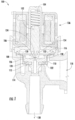
- FIG. 1 the pilot operated water valve 100 is shown in a cross-section in the closed position. Armature 102 is biased by spring 104 against pilot member 106 of insert 108 such that diaphragm 110 sealingly contacts main valve seat 112. As can be seen in this view, diaphragm 110 separates the internal valving cavity of the pilot operated water valve 100 into inlet chamber 114 and outlet chamber 116 situated respectively on either side of diaphragm 110. In the closed position, water entering inlet 118 may proceed into inlet chamber 114. This water may then pass through diaphragm 110 by way of a plurality of passageways 120 and 122 formed through diaphragm 110. However, one skilled in the art will recognize, in view of the present disclosure, that more or fewer passageways may be utilized.
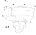
- FIG. 2 illustrates one embodiment of insert 108.
- insert 108 two identical bleed slots 126 and 128 are included and located on opposite sides of insert 108.
- bleed slot 126 is tapered, large at the bottom and a specific size at the top.
- the size of the top of bleed slots 126 and 128 determines the ratio to center hole of pilot passageway 124 for opening, as shown in FIG. 1 . That is, the rate of water flow that is allowed from the inlet chamber 114 to the outlet chamber 116 is governed by these and is less than the rate at which water flows out of the outlet chamber 116 through the pilot passageway 124 in order to allow the valve to open.
- each bleed slots 126 and 128 Located at the top of each bleed slots 126 and 128 is a scallop 140. Scallop 140 for bleed slot 126 can be seen in this illustration, while scallop 142 of bleed slot 128 can be seen in FIG. 3 .
- the upper edge 144 of insert 108 also has notches 146 and 148 through which water can flow into the center of insert 108 (particularly when water valve 100 is open as shown in FIG. 3 when the upper edge 144 is in contact with the underside of the solenoid actuator 136). Insert 108 has four notches in one embodiment, two of which are not shown in this FIG. 2 . However, one skilled in the art would recognize, in view of the present disclosure, that more or fewer notches may be utilized.
- scallops 140 and 142 meet with the inner wall of diaphragm 110 to form bleed holes 130 and 132, respectively, as seen in FIG. 1 .
- the increasing taper of bleed slots 126 and 128 allows in-rushing water to accelerate as it moves towards to narrower top of bleed slots 126 and 128. This increases the force with which the water exits through bleed holes 130 and 132, causing the water to flush out any contaminants that may have become stuck.
- FIG. 3 one embodiment of water valve 100 is shown in a cross-section in the opened position.
- electrical current must be applied to solenoid actuator 136.
- armature 102 moves upward and unseats seal member 134 from pilot member 106 thereby exposing the uppermost opening of pilot passageway 124 to outlet chamber 116.
- the water in outlet chamber 116 is pressurized at the same pressure as that of the water in inlet chamber 114, and assuming the pressure through outlet 138 and pilot passageway 124 is less than that of inlet chamber 114, this water then proceeds to evacuate from outlet chamber 116 through pilot passageway 124 to outlet 138.
- the water in water valve 100 is also in fluid communication with inlet chamber 114 and outlet chamber 116 in the open position.
- water in inlet chamber 114 may pass through diaphragm 110 by way of a plurality of passageways 120 and 122 then process up bleed slots 126 and 128 and flow into outlet chamber 116 through the exposed tops of bleed slots 126 and 128.
- From outlet chamber 116 water can flow through notches 146 and 148, on the upper edge 144 of insert 108, into the center of insert 108. Once in the center of insert 108, the water can then flow through pilot passageway 124 to outlet 138 until the solenoid is de-energized to close the pilot passageway 124.
- the differential pressure acts to close the valve (as shown in FIG. 1 ).
- FIG. 4 illustrates an enlarged view of bleed slot 128 of water valve 100 in the closed position.
- diaphragm 110 is closed around insert 108.
- Bleed slot 128 forms a passageway in conjunction with the inner wall of diaphragm 110.
- Scallop 142 on upper edge 144 of insert 108 contacts the inner wall of diaphragm 110 to form bleed hole 132.
Landscapes
- Engineering & Computer Science (AREA)
- General Engineering & Computer Science (AREA)
- Mechanical Engineering (AREA)
- Physics & Mathematics (AREA)
- Fluid Mechanics (AREA)
- Fluid-Driven Valves (AREA)
- Lift Valve (AREA)
- Self-Closing Valves And Venting Or Aerating Valves (AREA)
Claims (9)
- Une vanne à commande pilote (100), comprenant :un corps de vanne ayant une entrée (118), une cavité de vanne interne, et une sortie (138) ;un élément de vanne principal positionné dans la cavité de vanne interne et pouvant fonctionner pour contrôler un écoulement principal d'eau à partir de l'entrée (118) jusqu'à la sortie (138) ;l'élément de vanne principal comprenant un diaphragme (110) positionné dans le corps de vanne pour diviser la cavité de vanne interne en une chambre d'entrée (114) et une chambre de sortie (116), et un insert (108) couplé de manière opérationnelle au diaphragme (110) et coopérant avec celui-ci ;caractérisée en ce que :
le diaphragme (110) définit au moins un passage (120, 122) à travers celui-ci positionné pour coopérer avec au moins une fente de purge effilée (126, 128) définie dans une paroi extérieure de l'insert (108) et ayant un fond large et un sommet plus étroit, de sorte que l'effilement croissante de la fente de purge (126, 128) accélère l'eau entrante lorsqu'elle passe vers le sommet plus étroit de la fente de purge et dans la chambre de sortie (116). - La vanne à commande pilote selon la revendication 1, l'insert (108) définissant en outre au moins une échancrure (140, 142) au niveau d'un bord supérieur (144) de celui-ci, et l'au moins une échancrure (140, 142) coopérant avec le diaphragme (110) pour former au moins un trou de purge (130, 132) lorsque l'élément de vanne principal est dans une position fermée.
- La vanne à commande pilote selon la revendication 2, l'au moins un passage (120, 122), l'au moins une fente de purge effilée (126, 128), et l'au moins un trou de purge (130, 132) coopérant pour fournir une communication fluidique entre la chambre d'entrée (114) et la chambre de sortie (116) ; ou le diaphragme (110) définissant une pluralité de passages (120, 122) à travers celui-ci positionnés pour coopérer avec une pluralité de fentes de purge effilées (126, 128) définies dans une paroi extérieure de l'insert (108), et l'insert (108) définissant en outre une pluralité d'échancrures (140, 142) au niveau d'un bord supérieur (144) de celui-ci qui coopèrent avec le diaphragme (110) pour former une pluralité de trous de purge (130, 132) lorsque l'élément de vanne principal est dans une position fermée.
- La vanne à commande pilote selon la revendication 2, le diaphragme (110) définissant un premier passage (120, 122) et un second passage (120, 122) à travers celui-ci positionnés pour coopérer avec une première fente de purge effilée (126, 128) et une seconde fente de purge effilée (126, 128), respectivement, définies dans une paroi extérieure de l'insert (108), et l'insert (108) définissant en outre une première échancrure (140, 142) et une seconde échancrure (140, 142) au niveau d'un bord supérieur (144) de celui-ci qui coopèrent chacune avec le diaphragme (110) pour former un premier trou de purge (130, 132) et un second trou de purge (130, 132) lorsque l'élément de vanne principal est dans une position fermée.
- La vanne à commande pilote selon la revendication 4, le premier passage (120, 122), la première fente de purge effilée (126, 128) et le premier trou de purge (130, 132) coopérant pour fournir une communication fluidique entre la chambre d'entrée (114) et la chambre de sortie (116), et le second passage (120, 122), la seconde fente de purge effilée (126, 128) et le second trou de purge (130, 132) coopérant pour fournir une communication fluidique entre la chambre d'entrée (114) et la chambre de sortie (116).
- La vanne à commande pilote selon la revendication 2, une courbure d'une paroi interne du diaphragme (110) formant, à l'endroit où le contact est fait avec l'échancrure (140, 142), un bord le plus externe du trou de purge (130, 132) qui est infundibulaire.
- La vanne à commande pilote selon la revendication 1, le bord supérieur (144) de l'insert (108) définissant en outre au moins une encoche (146, 148) configurée pour permettre un écoulement d'eau dans une base en forme de cuvette de l'insert (108) lorsque l'élément de vanne principal est dans une position ouverte ; ou la fente de purge effilée (126, 128) ayant une première largeur proximale au passage (120, 122) à travers le diaphragme (110) et une seconde largeur distale au passage (120, 122) à travers le diaphragme (110) ; ou la fente de purge effilée (126, 128) étant configurée de telle sorte qu'un écoulement de fluide à travers celle-ci à partir de la chambre d'entrée (114) jusqu'à la chambre de sortie (116) s'accélère de manière à aider à éliminer des contaminants piégés dans la fente de purge effilée (126, 128).
- La vanne à commande pilote selon la revendication 1, le diaphragme (110) et l'insert (108) se séparant au moins partiellement lorsque l'élément de vanne principal est dans une position ouverte pour exposer la fente de purge effilée (126, 128) à la chambre de sortie (116), le diaphragme (110) de préférence s'enroulant pour entrer en contact avec la paroi extérieure de l'insert (108) lorsque l'élément de vanne principal passe d'une position ouverte à une position fermée, créant ainsi une action d'essuyage pour chasser des débris piégés de la fente de purge effilée (126, 128).
- La vanne à commande pilote selon la revendication 2, le diaphragme (110) et l'insert (108) se séparant au moins partiellement lorsque l'élément de vanne principal est dans une position ouverte pour exposer l'échancrure (140, 142) à la chambre de sortie (116).
Applications Claiming Priority (1)
| Application Number | Priority Date | Filing Date | Title |
|---|---|---|---|
| US16/213,778 US11300223B2 (en) | 2018-12-07 | 2018-12-07 | Self-cleaning water passageways on diaphragm insert |
Publications (3)
| Publication Number | Publication Date |
|---|---|
| EP3674589A2 EP3674589A2 (fr) | 2020-07-01 |
| EP3674589A3 EP3674589A3 (fr) | 2020-09-16 |
| EP3674589B1 true EP3674589B1 (fr) | 2023-05-03 |
Family
ID=68806625
Family Applications (1)
| Application Number | Title | Priority Date | Filing Date |
|---|---|---|---|
| EP19213765.1A Active EP3674589B1 (fr) | 2018-12-07 | 2019-12-05 | Passages d'eau autonettoyants sur un insert de diaphragme |
Country Status (2)
| Country | Link |
|---|---|
| US (1) | US11300223B2 (fr) |
| EP (1) | EP3674589B1 (fr) |
Family Cites Families (11)
| Publication number | Priority date | Publication date | Assignee | Title |
|---|---|---|---|---|
| GB2296075B (en) | 1994-12-12 | 1998-08-05 | Elbi Int Spa | A support and guide unit for an obturator of a solenoid valve and a method for the manufacture thereof |
| DE69629452T2 (de) * | 1995-09-08 | 2004-07-01 | Toto Ltd., Kita-Kyushu | Elektromagnet und elektromagnetventil |
| US5887848A (en) * | 1997-09-18 | 1999-03-30 | Sloan Valve Company | Flush valve bypass and filter |
| US7093529B2 (en) * | 2004-10-14 | 2006-08-22 | Delaware Capital Formation, Inc. | Composite piston |
| KR101832999B1 (ko) * | 2009-11-20 | 2018-04-13 | 엘비 인터내셔널 에스.피.에이. | 전자기 밸브 장치 |
| ITTO20111148A1 (it) * | 2011-12-14 | 2013-06-15 | Elbi Int Spa | Valvola pilota a solenoide per una valvola idraulica, particolarmente per apparecchi elettrodomestici |
| CA2946628C (fr) * | 2012-04-20 | 2018-05-15 | Sdb Ip Holdings, Llc | Piston rigide adapte a un robinet de chasse a membrane |
| US9033305B2 (en) * | 2013-03-14 | 2015-05-19 | Prettl | Water valve with supported opening function |
| EP3227593B1 (fr) * | 2014-12-03 | 2020-09-30 | Hydralectric Group Ltd | Soupape proportionnelle, et douche électrique et robinet incorporant la soupape proportionnelle |
| KR20170033724A (ko) * | 2015-09-17 | 2017-03-27 | 바이트론 인더스트리즈 차이나 | 다이어프램 구조 및 이를 포함하는 다이어프램 밸브 |
| JP2017201198A (ja) * | 2016-05-06 | 2017-11-09 | Toto株式会社 | 流量調整バルブ |
-
2018
- 2018-12-07 US US16/213,778 patent/US11300223B2/en active Active
-
2019
- 2019-12-05 EP EP19213765.1A patent/EP3674589B1/fr active Active
Also Published As
| Publication number | Publication date |
|---|---|
| EP3674589A3 (fr) | 2020-09-16 |
| US11300223B2 (en) | 2022-04-12 |
| EP3674589A2 (fr) | 2020-07-01 |
| US20200182370A1 (en) | 2020-06-11 |
Similar Documents
| Publication | Publication Date | Title |
|---|---|---|
| EP0631077A1 (fr) | Soupape d'eau avec prévention de l'obstruction | |
| US6457697B1 (en) | Foreign particle resistant valve | |
| CA2854045C (fr) | Siege de soupape anti-cavitation | |
| EP2331758B1 (fr) | Clapet de rinçage pour système d évacuation des eaux usées sous vide | |
| JP4587419B2 (ja) | メタルダイヤフラム弁 | |
| US7007916B2 (en) | Low flow valve improvement | |
| KR101909759B1 (ko) | 롤 오버 밸브 | |
| JPS5949381B2 (ja) | 洗浄弁 | |
| CN101743425B (zh) | 阀 | |
| KR102080603B1 (ko) | 스템용 가이드부를 구비한 리플레이스 시트 및 이를 포함하는 밸브 | |
| CN103669519B (zh) | 活塞式冲水阀 | |
| EP3674589B1 (fr) | Passages d'eau autonettoyants sur un insert de diaphragme | |
| EP1519091B1 (fr) | Robinet à manchon déformable | |
| KR20140073954A (ko) | 복층 시트부 구조를 갖는 글로브 밸브 | |
| EP3396218A1 (fr) | Soupape pilotée à insert étendu | |
| KR102225407B1 (ko) | 유량조절 및 개폐 기능을 가지는 고압용 밸브 | |
| CA2869834C (fr) | Robinet a piston rigide comprenant un solenoide | |
| KR101736026B1 (ko) | 인서트 바디가 구비되는 게이트 밸브 | |
| JPH0649877A (ja) | 貯水槽用ボールタップ | |
| JP3383945B2 (ja) | フィルタレギュレータ用オートドレン弁 | |
| US3439896A (en) | Pilot type valve | |
| KR102387388B1 (ko) | 캐비테이션 및 채터링 현상을 방지하는 이중 시트링 구조의 컨트롤 밸브 | |
| JP4689318B2 (ja) | 開放弁 | |
| JP2022062497A5 (fr) | ||
| US7673352B2 (en) | Flush valve for water closets |
Legal Events
| Date | Code | Title | Description |
|---|---|---|---|
| PUAI | Public reference made under article 153(3) epc to a published international application that has entered the european phase |
Free format text: ORIGINAL CODE: 0009012 |
|
| STAA | Information on the status of an ep patent application or granted ep patent |
Free format text: STATUS: THE APPLICATION HAS BEEN PUBLISHED |
|
| AK | Designated contracting states |
Kind code of ref document: A2 Designated state(s): AL AT BE BG CH CY CZ DE DK EE ES FI FR GB GR HR HU IE IS IT LI LT LU LV MC MK MT NL NO PL PT RO RS SE SI SK SM TR |
|
| AX | Request for extension of the european patent |
Extension state: BA ME |
|
| PUAL | Search report despatched |
Free format text: ORIGINAL CODE: 0009013 |
|
| AK | Designated contracting states |
Kind code of ref document: A3 Designated state(s): AL AT BE BG CH CY CZ DE DK EE ES FI FR GB GR HR HU IE IS IT LI LT LU LV MC MK MT NL NO PL PT RO RS SE SI SK SM TR |
|
| AX | Request for extension of the european patent |
Extension state: BA ME |
|
| RIC1 | Information provided on ipc code assigned before grant |
Ipc: F16K 31/385 20060101ALI20200811BHEP Ipc: F16K 31/40 20060101ALI20200811BHEP Ipc: F16K 31/383 20060101AFI20200811BHEP |
|
| RAP1 | Party data changed (applicant data changed or rights of an application transferred) |
Owner name: ROBERTSHAW CONTROLS COMPANY |
|
| STAA | Information on the status of an ep patent application or granted ep patent |
Free format text: STATUS: REQUEST FOR EXAMINATION WAS MADE |
|
| 17P | Request for examination filed |
Effective date: 20210316 |
|
| RBV | Designated contracting states (corrected) |
Designated state(s): AL AT BE BG CH CY CZ DE DK EE ES FI FR GB GR HR HU IE IS IT LI LT LU LV MC MK MT NL NO PL PT RO RS SE SI SK SM TR |
|
| GRAP | Despatch of communication of intention to grant a patent |
Free format text: ORIGINAL CODE: EPIDOSNIGR1 |
|
| STAA | Information on the status of an ep patent application or granted ep patent |
Free format text: STATUS: GRANT OF PATENT IS INTENDED |
|
| RIC1 | Information provided on ipc code assigned before grant |
Ipc: F16K 31/40 20060101ALI20221019BHEP Ipc: F16K 31/385 20060101ALI20221019BHEP Ipc: F16K 31/383 20060101AFI20221019BHEP |
|
| INTG | Intention to grant announced |
Effective date: 20221111 |
|
| GRAS | Grant fee paid |
Free format text: ORIGINAL CODE: EPIDOSNIGR3 |
|
| GRAA | (expected) grant |
Free format text: ORIGINAL CODE: 0009210 |
|
| STAA | Information on the status of an ep patent application or granted ep patent |
Free format text: STATUS: THE PATENT HAS BEEN GRANTED |
|
| AK | Designated contracting states |
Kind code of ref document: B1 Designated state(s): AL AT BE BG CH CY CZ DE DK EE ES FI FR GB GR HR HU IE IS IT LI LT LU LV MC MK MT NL NO PL PT RO RS SE SI SK SM TR |
|
| REG | Reference to a national code |
Ref country code: GB Ref legal event code: FG4D |
|
| REG | Reference to a national code |
Ref country code: AT Ref legal event code: REF Ref document number: 1564861 Country of ref document: AT Kind code of ref document: T Effective date: 20230515 Ref country code: CH Ref legal event code: EP |
|
| REG | Reference to a national code |
Ref country code: DE Ref legal event code: R096 Ref document number: 602019028318 Country of ref document: DE |
|
| REG | Reference to a national code |
Ref country code: IE Ref legal event code: FG4D |
|
| REG | Reference to a national code |
Ref country code: LT Ref legal event code: MG9D |
|
| REG | Reference to a national code |
Ref country code: NL Ref legal event code: MP Effective date: 20230503 |
|
| REG | Reference to a national code |
Ref country code: AT Ref legal event code: MK05 Ref document number: 1564861 Country of ref document: AT Kind code of ref document: T Effective date: 20230503 |
|
| PG25 | Lapsed in a contracting state [announced via postgrant information from national office to epo] |
Ref country code: SE Free format text: LAPSE BECAUSE OF FAILURE TO SUBMIT A TRANSLATION OF THE DESCRIPTION OR TO PAY THE FEE WITHIN THE PRESCRIBED TIME-LIMIT Effective date: 20230503 Ref country code: PT Free format text: LAPSE BECAUSE OF FAILURE TO SUBMIT A TRANSLATION OF THE DESCRIPTION OR TO PAY THE FEE WITHIN THE PRESCRIBED TIME-LIMIT Effective date: 20230904 Ref country code: NO Free format text: LAPSE BECAUSE OF FAILURE TO SUBMIT A TRANSLATION OF THE DESCRIPTION OR TO PAY THE FEE WITHIN THE PRESCRIBED TIME-LIMIT Effective date: 20230803 Ref country code: NL Free format text: LAPSE BECAUSE OF FAILURE TO SUBMIT A TRANSLATION OF THE DESCRIPTION OR TO PAY THE FEE WITHIN THE PRESCRIBED TIME-LIMIT Effective date: 20230503 Ref country code: ES Free format text: LAPSE BECAUSE OF FAILURE TO SUBMIT A TRANSLATION OF THE DESCRIPTION OR TO PAY THE FEE WITHIN THE PRESCRIBED TIME-LIMIT Effective date: 20230503 Ref country code: AT Free format text: LAPSE BECAUSE OF FAILURE TO SUBMIT A TRANSLATION OF THE DESCRIPTION OR TO PAY THE FEE WITHIN THE PRESCRIBED TIME-LIMIT Effective date: 20230503 |
|
| PG25 | Lapsed in a contracting state [announced via postgrant information from national office to epo] |
Ref country code: RS Free format text: LAPSE BECAUSE OF FAILURE TO SUBMIT A TRANSLATION OF THE DESCRIPTION OR TO PAY THE FEE WITHIN THE PRESCRIBED TIME-LIMIT Effective date: 20230503 Ref country code: PL Free format text: LAPSE BECAUSE OF FAILURE TO SUBMIT A TRANSLATION OF THE DESCRIPTION OR TO PAY THE FEE WITHIN THE PRESCRIBED TIME-LIMIT Effective date: 20230503 Ref country code: LV Free format text: LAPSE BECAUSE OF FAILURE TO SUBMIT A TRANSLATION OF THE DESCRIPTION OR TO PAY THE FEE WITHIN THE PRESCRIBED TIME-LIMIT Effective date: 20230503 Ref country code: LT Free format text: LAPSE BECAUSE OF FAILURE TO SUBMIT A TRANSLATION OF THE DESCRIPTION OR TO PAY THE FEE WITHIN THE PRESCRIBED TIME-LIMIT Effective date: 20230503 Ref country code: IS Free format text: LAPSE BECAUSE OF FAILURE TO SUBMIT A TRANSLATION OF THE DESCRIPTION OR TO PAY THE FEE WITHIN THE PRESCRIBED TIME-LIMIT Effective date: 20230903 Ref country code: HR Free format text: LAPSE BECAUSE OF FAILURE TO SUBMIT A TRANSLATION OF THE DESCRIPTION OR TO PAY THE FEE WITHIN THE PRESCRIBED TIME-LIMIT Effective date: 20230503 Ref country code: GR Free format text: LAPSE BECAUSE OF FAILURE TO SUBMIT A TRANSLATION OF THE DESCRIPTION OR TO PAY THE FEE WITHIN THE PRESCRIBED TIME-LIMIT Effective date: 20230804 |
|
| PG25 | Lapsed in a contracting state [announced via postgrant information from national office to epo] |
Ref country code: FI Free format text: LAPSE BECAUSE OF FAILURE TO SUBMIT A TRANSLATION OF THE DESCRIPTION OR TO PAY THE FEE WITHIN THE PRESCRIBED TIME-LIMIT Effective date: 20230503 |
|
| PG25 | Lapsed in a contracting state [announced via postgrant information from national office to epo] |
Ref country code: SK Free format text: LAPSE BECAUSE OF FAILURE TO SUBMIT A TRANSLATION OF THE DESCRIPTION OR TO PAY THE FEE WITHIN THE PRESCRIBED TIME-LIMIT Effective date: 20230503 |
|
| PG25 | Lapsed in a contracting state [announced via postgrant information from national office to epo] |
Ref country code: SM Free format text: LAPSE BECAUSE OF FAILURE TO SUBMIT A TRANSLATION OF THE DESCRIPTION OR TO PAY THE FEE WITHIN THE PRESCRIBED TIME-LIMIT Effective date: 20230503 Ref country code: SK Free format text: LAPSE BECAUSE OF FAILURE TO SUBMIT A TRANSLATION OF THE DESCRIPTION OR TO PAY THE FEE WITHIN THE PRESCRIBED TIME-LIMIT Effective date: 20230503 Ref country code: RO Free format text: LAPSE BECAUSE OF FAILURE TO SUBMIT A TRANSLATION OF THE DESCRIPTION OR TO PAY THE FEE WITHIN THE PRESCRIBED TIME-LIMIT Effective date: 20230503 Ref country code: EE Free format text: LAPSE BECAUSE OF FAILURE TO SUBMIT A TRANSLATION OF THE DESCRIPTION OR TO PAY THE FEE WITHIN THE PRESCRIBED TIME-LIMIT Effective date: 20230503 Ref country code: DK Free format text: LAPSE BECAUSE OF FAILURE TO SUBMIT A TRANSLATION OF THE DESCRIPTION OR TO PAY THE FEE WITHIN THE PRESCRIBED TIME-LIMIT Effective date: 20230503 Ref country code: CZ Free format text: LAPSE BECAUSE OF FAILURE TO SUBMIT A TRANSLATION OF THE DESCRIPTION OR TO PAY THE FEE WITHIN THE PRESCRIBED TIME-LIMIT Effective date: 20230503 |
|
| REG | Reference to a national code |
Ref country code: DE Ref legal event code: R097 Ref document number: 602019028318 Country of ref document: DE |
|
| PLBE | No opposition filed within time limit |
Free format text: ORIGINAL CODE: 0009261 |
|
| STAA | Information on the status of an ep patent application or granted ep patent |
Free format text: STATUS: NO OPPOSITION FILED WITHIN TIME LIMIT |
|
| 26N | No opposition filed |
Effective date: 20240206 |
|
| PG25 | Lapsed in a contracting state [announced via postgrant information from national office to epo] |
Ref country code: SI Free format text: LAPSE BECAUSE OF FAILURE TO SUBMIT A TRANSLATION OF THE DESCRIPTION OR TO PAY THE FEE WITHIN THE PRESCRIBED TIME-LIMIT Effective date: 20230503 |
|
| PG25 | Lapsed in a contracting state [announced via postgrant information from national office to epo] |
Ref country code: SI Free format text: LAPSE BECAUSE OF FAILURE TO SUBMIT A TRANSLATION OF THE DESCRIPTION OR TO PAY THE FEE WITHIN THE PRESCRIBED TIME-LIMIT Effective date: 20230503 |
|
| REG | Reference to a national code |
Ref country code: DE Ref legal event code: R119 Ref document number: 602019028318 Country of ref document: DE |
|
| REG | Reference to a national code |
Ref country code: CH Ref legal event code: PL |
|
| PG25 | Lapsed in a contracting state [announced via postgrant information from national office to epo] |
Ref country code: LU Free format text: LAPSE BECAUSE OF NON-PAYMENT OF DUE FEES Effective date: 20231205 |
|
| PG25 | Lapsed in a contracting state [announced via postgrant information from national office to epo] |
Ref country code: MC Free format text: LAPSE BECAUSE OF FAILURE TO SUBMIT A TRANSLATION OF THE DESCRIPTION OR TO PAY THE FEE WITHIN THE PRESCRIBED TIME-LIMIT Effective date: 20230503 |
|
| GBPC | Gb: european patent ceased through non-payment of renewal fee |
Effective date: 20231205 |
|
| REG | Reference to a national code |
Ref country code: BE Ref legal event code: MM Effective date: 20231231 |
|
| PG25 | Lapsed in a contracting state [announced via postgrant information from national office to epo] |
Ref country code: MC Free format text: LAPSE BECAUSE OF FAILURE TO SUBMIT A TRANSLATION OF THE DESCRIPTION OR TO PAY THE FEE WITHIN THE PRESCRIBED TIME-LIMIT Effective date: 20230503 Ref country code: LU Free format text: LAPSE BECAUSE OF NON-PAYMENT OF DUE FEES Effective date: 20231205 |
|
| REG | Reference to a national code |
Ref country code: IE Ref legal event code: MM4A |
|
| PG25 | Lapsed in a contracting state [announced via postgrant information from national office to epo] |
Ref country code: DE Free format text: LAPSE BECAUSE OF NON-PAYMENT OF DUE FEES Effective date: 20240702 Ref country code: IE Free format text: LAPSE BECAUSE OF NON-PAYMENT OF DUE FEES Effective date: 20231205 |
|
| PG25 | Lapsed in a contracting state [announced via postgrant information from national office to epo] |
Ref country code: GB Free format text: LAPSE BECAUSE OF NON-PAYMENT OF DUE FEES Effective date: 20231205 |
|
| PG25 | Lapsed in a contracting state [announced via postgrant information from national office to epo] |
Ref country code: BE Free format text: LAPSE BECAUSE OF NON-PAYMENT OF DUE FEES Effective date: 20231231 |
|
| PG25 | Lapsed in a contracting state [announced via postgrant information from national office to epo] |
Ref country code: FR Free format text: LAPSE BECAUSE OF NON-PAYMENT OF DUE FEES Effective date: 20231231 |
|
| PG25 | Lapsed in a contracting state [announced via postgrant information from national office to epo] |
Ref country code: CH Free format text: LAPSE BECAUSE OF NON-PAYMENT OF DUE FEES Effective date: 20231231 |
|
| PG25 | Lapsed in a contracting state [announced via postgrant information from national office to epo] |
Ref country code: IE Free format text: LAPSE BECAUSE OF NON-PAYMENT OF DUE FEES Effective date: 20231205 Ref country code: GB Free format text: LAPSE BECAUSE OF NON-PAYMENT OF DUE FEES Effective date: 20231205 Ref country code: FR Free format text: LAPSE BECAUSE OF NON-PAYMENT OF DUE FEES Effective date: 20231231 Ref country code: DE Free format text: LAPSE BECAUSE OF NON-PAYMENT OF DUE FEES Effective date: 20240702 Ref country code: CH Free format text: LAPSE BECAUSE OF NON-PAYMENT OF DUE FEES Effective date: 20231231 Ref country code: BE Free format text: LAPSE BECAUSE OF NON-PAYMENT OF DUE FEES Effective date: 20231231 |
|
| PG25 | Lapsed in a contracting state [announced via postgrant information from national office to epo] |
Ref country code: BG Free format text: LAPSE BECAUSE OF FAILURE TO SUBMIT A TRANSLATION OF THE DESCRIPTION OR TO PAY THE FEE WITHIN THE PRESCRIBED TIME-LIMIT Effective date: 20230503 |
|
| PG25 | Lapsed in a contracting state [announced via postgrant information from national office to epo] |
Ref country code: BG Free format text: LAPSE BECAUSE OF FAILURE TO SUBMIT A TRANSLATION OF THE DESCRIPTION OR TO PAY THE FEE WITHIN THE PRESCRIBED TIME-LIMIT Effective date: 20230503 |
|
| PG25 | Lapsed in a contracting state [announced via postgrant information from national office to epo] |
Ref country code: CY Free format text: LAPSE BECAUSE OF FAILURE TO SUBMIT A TRANSLATION OF THE DESCRIPTION OR TO PAY THE FEE WITHIN THE PRESCRIBED TIME-LIMIT; INVALID AB INITIO Effective date: 20191205 |
|
| PG25 | Lapsed in a contracting state [announced via postgrant information from national office to epo] |
Ref country code: HU Free format text: LAPSE BECAUSE OF FAILURE TO SUBMIT A TRANSLATION OF THE DESCRIPTION OR TO PAY THE FEE WITHIN THE PRESCRIBED TIME-LIMIT; INVALID AB INITIO Effective date: 20191205 |
|
| PG25 | Lapsed in a contracting state [announced via postgrant information from national office to epo] |
Ref country code: TR Free format text: LAPSE BECAUSE OF FAILURE TO SUBMIT A TRANSLATION OF THE DESCRIPTION OR TO PAY THE FEE WITHIN THE PRESCRIBED TIME-LIMIT Effective date: 20230503 |