EP3674586B1 - Valve - Google Patents
Valve Download PDFInfo
- Publication number
- EP3674586B1 EP3674586B1 EP19216932.4A EP19216932A EP3674586B1 EP 3674586 B1 EP3674586 B1 EP 3674586B1 EP 19216932 A EP19216932 A EP 19216932A EP 3674586 B1 EP3674586 B1 EP 3674586B1
- Authority
- EP
- European Patent Office
- Prior art keywords
- channel
- obstacle
- valve
- axis
- rotation
- Prior art date
- Legal status (The legal status is an assumption and is not a legal conclusion. Google has not performed a legal analysis and makes no representation as to the accuracy of the status listed.)
- Active
Links
- 239000012530 fluid Substances 0.000 claims description 21
- 238000011144 upstream manufacturing Methods 0.000 claims description 5
- 230000000903 blocking effect Effects 0.000 claims 15
- VNWKTOKETHGBQD-UHFFFAOYSA-N methane Chemical compound C VNWKTOKETHGBQD-UHFFFAOYSA-N 0.000 description 2
- 241000287107 Passer Species 0.000 description 1
- QVGXLLKOCUKJST-UHFFFAOYSA-N atomic oxygen Chemical compound [O] QVGXLLKOCUKJST-UHFFFAOYSA-N 0.000 description 1
- 230000033228 biological regulation Effects 0.000 description 1
- 230000000295 complement effect Effects 0.000 description 1
- 230000021615 conjugation Effects 0.000 description 1
- 230000007423 decrease Effects 0.000 description 1
- 238000006073 displacement reaction Methods 0.000 description 1
- 230000000694 effects Effects 0.000 description 1
- 239000001257 hydrogen Substances 0.000 description 1
- 229910052739 hydrogen Inorganic materials 0.000 description 1
- 125000004435 hydrogen atom Chemical class [H]* 0.000 description 1
- 239000007788 liquid Substances 0.000 description 1
- 230000009063 long-term regulation Effects 0.000 description 1
- 238000000034 method Methods 0.000 description 1
- 239000001301 oxygen Substances 0.000 description 1
- 229910052760 oxygen Inorganic materials 0.000 description 1
- 230000000750 progressive effect Effects 0.000 description 1
- 230000001105 regulatory effect Effects 0.000 description 1
- 230000007704 transition Effects 0.000 description 1
Images


Classifications
-
- F—MECHANICAL ENGINEERING; LIGHTING; HEATING; WEAPONS; BLASTING
- F16—ENGINEERING ELEMENTS AND UNITS; GENERAL MEASURES FOR PRODUCING AND MAINTAINING EFFECTIVE FUNCTIONING OF MACHINES OR INSTALLATIONS; THERMAL INSULATION IN GENERAL
- F16K—VALVES; TAPS; COCKS; ACTUATING-FLOATS; DEVICES FOR VENTING OR AERATING
- F16K5/00—Plug valves; Taps or cocks comprising only cut-off apparatus having at least one of the sealing faces shaped as a more or less complete surface of a solid of revolution, the opening and closing movement being predominantly rotary
- F16K5/06—Plug valves; Taps or cocks comprising only cut-off apparatus having at least one of the sealing faces shaped as a more or less complete surface of a solid of revolution, the opening and closing movement being predominantly rotary with plugs having spherical surfaces; Packings therefor
- F16K5/0605—Plug valves; Taps or cocks comprising only cut-off apparatus having at least one of the sealing faces shaped as a more or less complete surface of a solid of revolution, the opening and closing movement being predominantly rotary with plugs having spherical surfaces; Packings therefor with particular plug arrangements, e.g. particular shape or built-in means
-
- F—MECHANICAL ENGINEERING; LIGHTING; HEATING; WEAPONS; BLASTING
- F16—ENGINEERING ELEMENTS AND UNITS; GENERAL MEASURES FOR PRODUCING AND MAINTAINING EFFECTIVE FUNCTIONING OF MACHINES OR INSTALLATIONS; THERMAL INSULATION IN GENERAL
- F16K—VALVES; TAPS; COCKS; ACTUATING-FLOATS; DEVICES FOR VENTING OR AERATING
- F16K5/00—Plug valves; Taps or cocks comprising only cut-off apparatus having at least one of the sealing faces shaped as a more or less complete surface of a solid of revolution, the opening and closing movement being predominantly rotary
- F16K5/08—Details
- F16K5/12—Arrangements for modifying the way in which the rate of flow varies during the actuation of the valve
Definitions
- the present invention relates to a valve.
- the first and second obstacle elements each comprise a second surface oriented towards an axis of symmetry of the channel.
- the second surfaces of the first and second obstacle elements are curved and convex.
- the valve is arranged so that, in the closed position, the rotary shutter is partially engaged between the first and the second obstacle elements.
- This offset is preferably 0.5 to 5%, for example 2% of the diameter of the channel. This allows the rotary shutter to be shifted downstream to the closed position. The friction between the rotary shutter and the seal is then less, which decreases the wear of the seal, and improves the tightness and precision of long-term regulation.
- the third obstacle element includes a surface parallel to the axis of rotation.
- the valve comprises at most three obstacle elements.
- the area of the obstacle represents 10% to 40% of the area of a section of the channel, preferably 20% to 30% of the area of a section of the channel. channel.
- the invention further provides a use of a valve according to any one of the embodiments of the invention, the use comprising a rotation of the rotary shutter about the axis of rotation.
- first and second are used only to differentiate between the different elements and do not imply order between these elements.
- the part of the channel 2 which is not obstructed by the obstacle 3 can be called the bottleneck 23.
- the bottleneck 23 does not vary over time.
- the second surfaces 34a, 34b are turned towards the axis of symmetry 26 so as to be at least partially opposed to the respective first surfaces 33a, 33b.
- the first and second surfaces 33a, 33b, 34a, 34b are preferably curved and convex.
- each of the protrusions 32a, 32b forms a point which is directed towards the median plane 25, but preferably not in a direction perpendicular to the median plane 25.
- the obstacle 3 preferably comprises a third obstacle element 31c. It is symmetrical with respect to the median plane 25. It is preferably located in the channel 2 opposite the first part 21 of the channel.
- the third obstacle element 31c may comprise a surface 32c parallel to the axis of rotation 51.
- the obstacle 3 preferably does not include any obstacle elements other than the first 31a, second 31b and third 31c obstacle elements.
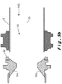
- the figure 3a is a schematic sectional view in the median plane 25, and illustrating a valve 1 according to an embodiment of the invention in a closed position 101.
- the figure 3b is a schematic sectional view in a plane comprising the axis of symmetry 26 and perpendicular to the median plane 25, and illustrating a valve 1 according to an embodiment of the invention in a closed position 101.
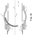
- the figures 4a and 4b correspond to a position 102 intermediate between the closed position 101 and an open position 103.
- the figures 5a and 5b correspond to the open position 103.
- These figures illustrate a seal 92 making it possible to avoid leaks between the rotary shutter 5 and the obstacle 3 and a guide 91 making it possible to guide the rotation of the rotary shutter 5.
- the obstacle 3 is preferably located upstream of the axis of rotation 51 relative to the movement of fluid.
- the part of the rotary shutter 5 which is in the channel 2, in particular the recess 52, is preferably symmetrical with respect to the median plane 25.
- the recess 52 In the closed position 101, the recess 52 is preferably open downstream and the rotary shutter 5 has a wall 53 directed essentially upstream.
- the arrow 55 represents the direction of rotation of the rotary shutter 5 between the closed position 101 and the open position 103.
- the rotary shutter 5 preferably rotates 90 ° around the axis of rotation 51 between the closed position. 101 and the open position 103.
- the third obstacle element 31c forms a screen for the part of the rotary shutter 5 which is in the median plane 25, and which may be called the median part of the rotary shutter 5.
- the first 31a and the second 31b obstacle elements form a screen for the parts of the rotary shutter 5 which are on either side of the recess 52 along the axis 51, and which can be called upper parts and lower part of the rotary shutter 5.
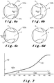
- the figure 6 is an elevational view illustrating the evolution of the position of the rotary shutter 5 as it moves through its rotary stroke.
- the arrow 56 is the direction of enlargement of the opening 4. This direction is parallel to the median plane 25.
- the protrusions 32a, 32b point both in a direction partially opposite to this direction of enlargement of the opening 4 and towards the median plane 25.
- the figure 6a corresponds to a first part 102a of the rotary stroke, which is the rotary stroke part between the closed position and the meeting of the opening 4 with the first and second obstacle elements 31a, 31b.
- the obstruction device 10 is preferably designed not to obstruct the opening 4 during the first part 102a of the rotary stroke in order to have a flow rate which increases rapidly as a function of the angle of rotation.
- the protrusions 32a, 32b are the parts of the first and second obstacle elements 31a, 31b which are first encountered by the opening 4.
- the figures 6b and 6c correspond to a second part 102b of the rotary stroke, which is the rotary stroke part between the meeting of the opening 4 with the first and second obstacle elements 31a, 31b and the meeting of the opening 4 with the third element obstacle 31c.
- a first object of the present invention is to obtain a slope of the flow rate curve 62 versus angle 61 in the first part 102a of the stroke. rotary which is high, in the second portion 102b of the rotary stroke which is low in order to allow regulation with high precision.
- a second object is to have at the end of the third part 102c of the rotary stroke the greatest flow rate value 62.
- the figure 6d corresponds to a third part 102c of the rotary stroke, which is the rotary stroke part after meeting the opening 4 with the third obstacle member 31c.
- the flow rate then hardly depends on the angle because almost all of the rotary shutter 5 is behind the obstacle 3.
- the invention relates in particular to a ball valve 1 for regulating a flow of fluid through a channel 2.
- the valve 1 comprises a rotary shutter 5 and an obstacle 3 located directly upstream of the shutter. rotary 5.
- the combined obstructions due to the rotary shutter 5 and the obstacle 3 reduce the possible passage for the fluid to an opening 4 whose area depends on the angle of rotation of the rotary shutter 5.
- the obstacle 3 comprises a first 31a and a second 31b obstacle elements located on either side of a median plane 25 perpendicular to the axis of rotation 51 of the rotary shutter 5.
- the first 31a and second 31b elements d The obstacle each have a protrusion 32a, 32b which points to the part 21 of channel 2 which is opened first when opening the valve 1.
Description
La présente invention concerne une vanne.The present invention relates to a valve.
Il existe des vannes comprenant un obturateur rotatif. Un problème de ces vannes est leur manque de précision. En effet, il est difficile de régler précisément le débit de fluide passant à travers ces vannes.There are valves including a rotary shutter. One problem with these valves is their lack of precision. Indeed, it is difficult to precisely regulate the flow of fluid passing through these valves.
Un objet de la présente invention est de fournir une vanne permettant de réguler plus finement le débit de fluide.An object of the present invention is to provide a valve making it possible to more finely regulate the flow of fluid.
A cet effet, l'invention propose une vanne comprenant un canal et un dispositif d'obstruction, le dispositif d'obstruction comprenant :
- un obstacle obstruant partiellement le canal de façon, l'obstacle comprenant un premier et un deuxième éléments d'obstacle couplés mécaniquement à une paroi intérieure du canal, et
- un obturateur rotatif agencé pour tourner autour d'un axe de rotation ; la vanne étant agencée pour avoir :
- une position fermée dans laquelle le dispositif d'obstruction obstrue au maximum le canal, et
- une position ouverte dans laquelle le dispositif d'obstruction obstrue au minimum le canal ;
dans laquelle le premier et le deuxième éléments d'obstacle ont une saillie tournée en direction de la première partie du canal.
- an obstacle partially obstructing the channel, the obstacle comprising first and second obstacle elements mechanically coupled to an interior wall of the channel, and
- a rotary shutter arranged to rotate about an axis of rotation; the valve being arranged to have:
- a closed position in which the obstruction device obstructs the channel as much as possible, and
- an open position in which the obstruction device minimally obstructs the channel;
wherein the first and second obstacle elements have a projection facing towards the first part of the channel.
Lorsque la vanne commence à s'ouvrir, c'est-à-dire lorsque l'obturateur rotatif commence à tourner, l'ouverture par laquelle peut passer le fluide est dans la première partie du canal. Cette ouverture a initialement une forme de croissant. Ce croissant s'agrandit au fur et à mesure que l'obturateur rotatif poursuit sa course rotative, de préférence sans rencontrer d'obstacle. C'est la première partie de la course rotative.When the valve begins to open, that is, when the rotary shutter begins to rotate, the opening through which the fluid can pass is in the first part of the channel. This opening initially has a crescent shape. This crescent increases as the rotary shutter continues its rotary stroke, preferably without encountering any obstacle. This is the first part of the rotary stroke.
Lorsque l'obturateur rotatif continue sa course rotative, l'ouverture rencontre les premier et deuxième éléments d'obstacle. La deuxième partie de la course rotative commence alors. Puisque les saillies des premier et deuxième éléments d'obstacle sont dirigées vers la première partie du canal, l'ouverture en forme de croissant peut s'étendre dans des creux entre la paroi du canal et les premier et deuxième éléments d'obstacle. Ainsi, les saillies permettent que la surface de l'ouverture qui correspond à la rencontre avec les premier et deuxième éléments d'obstacle soit particulièrement grande. Un premier effet des saillies est donc de permettre d'atteindre un grand débit pour un angle faible au début de la course rotative de l'obturateur rotatif.As the rotary shutter continues its rotary stroke, the opening encounters the first and second obstacle elements. The second part of the rotary stroke then begins. Since the protrusions of the first and second obstacle members are directed towards the first part of the channel, the crescent-shaped opening can extend into recesses between the wall of the channel and the first and second obstacle members. Thus, the projections allow the area of the opening which corresponds to the meeting with the first and second obstacle elements to be particularly large. A first effect of the projections is therefore to make it possible to achieve a high flow rate for a low angle at the start of the rotary stroke of the rotary shutter.
Dans la deuxième partie de la course rotative, l'ouverture continue à s'étendre et son aire peut dépendre de la forme des premier et deuxième éléments d'obstacle. Comme la rencontre de l'ouverture avec les saillies se produit à un angle de course faible tout en ayant un grand débit, l'ensemble de la deuxième partie de la course rotative peut correspondre à une amplitude angulaire importante. Ainsi, une variation de débit peut correspondre à une variation angulaire particulièrement grande de la course angulaire de l'obturateur rotatif. Par conséquent, il est possible en variant faiblement l'angle de rotation de l'obturateur rotatif, d'obtenir une variation de débit particulièrement petite. En d'autres termes, l'invention permet d'obtenir une grande résolution de débit dans la partie de la course angulaire de l'obturateur rotatif où le débit est grand.In the second part of the rotary stroke, the opening continues to expand and its area may depend on the shape of the first and second obstacle elements. Since the meeting of the opening with the protrusions occurs at a small stroke angle while having a large flow rate, the whole of the second part of the rotary stroke can correspond to a large angular amplitude. Thus, a variation in flow rate can correspond to a particularly large angular variation in the angular travel of the rotary shutter. Therefore, it is possible by slightly varying the angle of rotation of the rotary shutter, to obtain a particularly small variation in flow rate. In other words, the invention makes it possible to obtain a high flow resolution in the part of the angular travel of the rotary shutter where the flow rate is large.
Un avantage de l'invention est que l'obturateur rotatif, qui est un élément devant répondre à des spécifications particulièrement contraignantes puisqu'il tourne, peut être d'une forme relativement simple. En effet, la complexité de la forme de l'ouverture peut être reportée sur l'obstacle, qui ne tourne pas.An advantage of the invention is that the rotary shutter, which is an element having to meet particularly restrictive specifications since it rotates, can be of a relatively simple shape. Indeed, the complexity of the shape of the opening can be transferred to the obstacle, which does not turn.
La vanne est de préférence une vanne à boisseau creux. La vanne peut par exemple être une vanne cryogénique pour un moteur de fusée. Le fluide peut par exemple être de l'oxygène, de l'hydrogène, ou du méthane liquides ou gazeux..The valve is preferably a hollow plug valve. The valve can for example be a cryogenic valve for a rocket engine. The fluid can for example be liquid or gaseous oxygen, hydrogen, or methane.
Le canal est de section circulaire. La première partie du canal peut être vue par exemple comme la partie du canal correspondant à une rotation de 0° à 10° de l'obturateur rotatif à partir de la position fermée. Elle a de préférence une section en forme de croissant.The canal has a circular section. The first part of the channel can be seen for example as the part of the channel corresponding to a rotation of 0 ° to 10 ° of the rotary shutter from the closed position. It preferably has a crescent-shaped section.
L'obstacle est un élément d'obstruction du canal. Il est de préférence fixe. Il est couplé mécaniquement, de préférence fixé, à la surface intérieure du canal. Les premier, deuxième et optionnellement troisième éléments d'obstacle sont préférentiellement dans un même plan qui forme une section du canal. L'obstacle définit un goulet pour le fluide, qui est la partie du canal complémentaire de l'obstacle. Les saillies, qui peuvent être appelées « sommets » ou « crêtes » ou « pointes » peuvent être pointues ou arrondies.The obstacle is an obstruction element of the channel. It is preferably fixed. It is mechanically coupled, preferably fixed, to the interior surface of the channel. The first, second and optionally third obstacle elements are preferably in the same plane which forms a section of the channel. The obstacle defines a bottleneck for the fluid, which is the part of the complementary channel of the obstacle. The protrusions, which may be referred to as "tops" or "ridges" or "points" may be pointed or rounded.
L'obturateur rotatif peut être appelé cuillère ou boisseau creux. L'axe de rotation est de préférence perpendiculaire à la direction de passage du fluide dans le canal. De préférence, l'obturateur rotatif obstrue sur un secteur angulaire limité, d'environ 90° d'angle au centre. Le fluide passe à côté de l'obturateur, entre lui et la section du canal.The rotary shutter may be referred to as a hollow spoon or cup. The axis of rotation is preferably perpendicular to the direction of passage of the fluid in the channel. Preferably, the rotary shutter obstructs over a limited angular sector, of about 90 ° of angle in the center. The fluid passes next to the obturator, between it and the section of the channel.
La course ou course rotative est le déplacement angulaire de l'obturateur mobile entre la position fermée, qui correspond de préférence à un angle de 0°, et la position ouverte, qui correspond de préférence à un angle de 90°.The stroke or rotary stroke is the angular displacement of the movable shutter between the closed position, which preferably corresponds to an angle of 0 °, and the open position, which preferably corresponds to an angle of 90 °.
L'ouverture du canal est la partie de la section du canal au niveau du dispositif d'obstruction qui n'est pas obstruée par le dispositif d'obstruction. En position fermée, l'ouverture est minimale. En position ouverte, l'ouverture est maximale. En position ouverte, l'ouverture correspond de préférence au goulet défini par l'obstacle. En position fermée, l'ouverture est, de préférence, inexistante, car l'obturateur rotatif obstrue totalement le goulet défini par l'obstacle. Il y a une continuité de positions intermédiaires entre la position fermée et la position ouverte qui correspondent à l'agrandissement progressif de l'ouverture au fur et à mesure de la course.The opening of the channel is the part of the section of the channel at the level of the obstruction device which is not obstructed by the obstruction device. In the closed position, the opening is minimal. In the open position, the opening is maximum. In the open position, the opening preferably corresponds to the neck defined by the obstacle. In the closed position, the opening is preferably non-existent, since the rotary shutter completely obstructs the neck defined by the obstacle. There is a continuity of intermediate positions between the closed position and the open position which correspond to the progressive enlargement of the opening as the stroke progresses.
Dans un mode de réalisation de l'invention, l'obstacle est symétrique par rapport à un plan médian perpendiculaire à l'axe de rotation et qui sépare le canal en deux parties symétriques.In one embodiment of the invention, the obstacle is symmetrical with respect to a median plane perpendicular to the axis of rotation and which separates the channel into two symmetrical parts.
Cela permet d'éviter les pertes de charge dans le fluide.This makes it possible to avoid pressure drops in the fluid.
Dans un mode de réalisation de l'invention, le premier et le deuxième éléments d'obstacle comprennent chacun une première surface orientée vers la surface intérieure du canal.In one embodiment of the invention, the first and second obstacle elements each comprise a first surface oriented towards the interior surface of the channel.
Dans un mode de réalisation de l'invention, l'obstacle est tel qu'il existe un rayon de la section du canal qui part de la surface intérieure du canal, puis passe successivement par une partie de canal non-obstruée par l'obstacle (c'est-à-dire par un creux entre la surface intérieure du canal et le premier élément d'obstacle), par le premier élément d'obstacle puis par une partie de canal non-obstruée par l'obstacle et arrive au centre de la section du canal. De même pour le deuxième élément d'obstacle.In one embodiment of the invention, the obstacle is such that there is a radius of the section of the channel which starts from the interior surface of the channel, then passes successively through a part of the channel not obstructed by the obstacle. (i.e. by a hollow between the internal surface of the channel and the first obstacle element), by the first obstacle element then by a part of the channel not obstructed by the obstacle and arrives at the center of the canal section. Likewise for the second obstacle element.
Dans un mode de réalisation de l'invention, les premières surfaces des premier et deuxième éléments d'obstacle sont courbes et convexes.In one embodiment of the invention, the first surfaces of the first and second obstacle elements are curved and convex.
Cela permet d'avoir une ouverture en forme de croissant ayant une aire particulièrement grande durant la course de l'obturateur rotatif.This makes it possible to have a crescent-shaped opening having a particularly large area during the travel of the rotary shutter.
Dans un mode de réalisation de l'invention, la vanne est agencée pour que les premières surfaces des premier et deuxième éléments d'obstacle se superposent à la limite de l'évidement de l'obturateur rotatif lors de la transition entre la première partie de la course rotative et la deuxième partie de la course rotative.In one embodiment of the invention, the valve is arranged so that the first surfaces of the first and second elements obstacle overlap at the limit of the rotary shutter recess during the transition from the first part of the rotary stroke to the second part of the rotary stroke.
Dans un mode de réalisation de l'invention, le premier et le deuxième éléments d'obstacle comprennent chacun une deuxième surface orientée vers un axe de symétrie du canal.In one embodiment of the invention, the first and second obstacle elements each comprise a second surface oriented towards an axis of symmetry of the channel.
Dans un mode de réalisation de l'invention, les deuxième surfaces des premier et deuxième éléments d'obstacle sont courbes et convexes.In one embodiment of the invention, the second surfaces of the first and second obstacle elements are curved and convex.
Dans un mode de réalisation de l'invention, l'obstacle est situé en amont de l'axe de rotation par rapport au mouvement de fluide.In one embodiment of the invention, the obstacle is located upstream of the axis of rotation with respect to the movement of fluid.
Cela permet que l'obstacle fasse écran devant l'obturateur rotatif. Ainsi, les tensions subies par l'obturateur rotatif sont réduites et l'obturateur rotatif peut être particulièrement peu épais. Cette faible épaisseur permet que le couple exercé par le fluide sur la vanne soit particulièrement faible.This allows the obstacle to form a screen in front of the rotary shutter. Thus, the tensions undergone by the rotary shutter are reduced and the rotary shutter can be particularly thin. This small thickness allows the torque exerted by the fluid on the valve to be particularly low.
Dans un mode de réalisation de l'invention, la vanne est agencée pour qu'en position fermée, l'obturateur rotatif soit partiellement engagés entre le premier et le deuxième éléments d'obstacle.In one embodiment of the invention, the valve is arranged so that, in the closed position, the rotary shutter is partially engaged between the first and the second obstacle elements.
Cela permet de diminuer les fuites entre l'obturateur rotatif et les éléments d'obstacle.This makes it possible to reduce the leaks between the rotary shutter and the obstacle elements.
Dans un mode de réalisation de l'invention, l'obturateur rotatif comprend un évidement symétrique par rapport à un plan médian perpendiculaire à l'axe de rotation et qui sépare le canal en deux parties symétriques.In one embodiment of the invention, the rotary shutter comprises a recess symmetrical with respect to a median plane perpendicular to the axis of rotation and which separates the channel into two symmetrical parts.
Dans un mode de réalisation de l'invention, l'axe de rotation est décalé vers la première partie du canal par rapport à un axe de symétrie du canal.In one embodiment of the invention, the axis of rotation is offset towards the first part of the channel relative to an axis of symmetry of the channel.
Ce décalage est de préférence de 0,5 à 5%, par exemple de 2% du diamètre du canal. Cela permet de décaler l'obturateur rotatif vers l'aval en position fermée. Le frottement entre l'obturateur rotatif et le joint est alors moindre, ce qui diminue l'usure du joint, et améliore l'étanchéité et la précision de la régulation à long terme.This offset is preferably 0.5 to 5%, for example 2% of the diameter of the channel. This allows the rotary shutter to be shifted downstream to the closed position. The friction between the rotary shutter and the seal is then less, which decreases the wear of the seal, and improves the tightness and precision of long-term regulation.
L'obstacle comprend un troisième élément d'obstacle couplé mécaniquement à une paroi intérieure du canal et situé à l'opposé du canal par rapport à la première partie du canal.The obstacle includes a third obstacle element mechanically coupled to an interior wall of the channel and located opposite the channel from the first part of the channel.
Ce troisième élément d'obstacle correspond à la partie de la course où l'ouverture est très grande. A cause de l'épaisseur de l'obturateur rotatif, celui-ci obstrue partiellement le canal, même en position ouverte. Le troisième élément d'obstacle fait écran devant l'obturateur rotatif en position ouverte, ce qui permet de diminuer les tensions dans l'obturateur rotatif et de réduire les pertes de charge du fluide. Ainsi, la valeur de débit atteinte en fin de troisième partie de course est particulièrement haute. De préférence, en position ouverte, l'obturateur rotatif est complétement caché derrière l'obstacle.This third obstacle element corresponds to the part of the race where the opening is very large. Due to the thickness of the rotary shutter, it partially obstructs the channel, even in the open position. The third obstacle element screens in front of the rotary shutter in the open position, which makes it possible to reduce the tensions in the rotary shutter and to reduce the pressure drops of the fluid. Thus, the flow rate value reached at the end of the third part of the stroke is particularly high. Preferably, in the open position, the rotary shutter is completely hidden behind the obstacle.
Le troisième élément d'obstacle comprend une surface parallèle à l'axe de rotation.The third obstacle element includes a surface parallel to the axis of rotation.
Dans un mode de réalisation de l'invention, le troisième élément d'obstacle est disjoint des premier et deuxième éléments d'obstacle.In one embodiment of the invention, the third obstacle element is separate from the first and second obstacle elements.
Dans un mode de réalisation de l'invention, la vanne comprend au plus trois éléments d'obstacle.In one embodiment of the invention, the valve comprises at most three obstacle elements.
Dans un mode de réalisation de l'invention, l'aire de l'obstacle représente 10% à 40% de l'aire d'une section du canal, de préférence 20% à 30% de l'aire d'une section du canal.In one embodiment of the invention, the area of the obstacle represents 10% to 40% of the area of a section of the channel, preferably 20% to 30% of the area of a section of the channel. channel.
L'invention propose en outre une utilisation d'une vanne selon l'un quelconque des modes de réalisation de l'invention, l'utilisation comprenant une rotation de l'obturateur rotatif autour de l'axe de rotation.The invention further provides a use of a valve according to any one of the embodiments of the invention, the use comprising a rotation of the rotary shutter about the axis of rotation.
Les avantages mentionnés pour le dispositif s'appliquent mutatis mutandis à la méthode.The advantages mentioned for the device apply mutatis mutandis to the method.
D'autres caractéristiques et avantages de l'invention apparaîtront à la lecture de la description détaillée qui suit pour la compréhension de laquelle on se reportera aux figures annexées parmi lesquelles :
- la
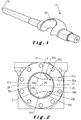
figure 1 illustre un exemple d'un obturateur rotatif qui peut être utilisé dans un mode de réalisation d'une vanne selon l'invention ; - la
figure 2 est une vue en élévation d'une partie d'une vanne selon un mode de réalisation de l'invention ; - la
figure 3a est une coupe schématique dans un plan médian, et illustrant une vanne selon un mode de réalisation de l'invention dans une position fermée ; - la
figure 3b est en coupe schématique dans un plan qui comprend un axe de symétrie du canal et qui perpendiculaire au plan médian, et illustrant une vanne selon un mode de réalisation de l'invention dans une position fermée ; - la
figure 4a est une coupe schématique dans un plan médian, et illustrant une vanne selon un mode de réalisation de l'invention dans une position intermédiaire ; - la
figure 4b est une coupe schématique dans un plan qui comprend un axe de symétrie du canal et qui perpendiculaire au plan médian, et illustrant une vanne selon un mode de réalisation de l'invention dans une position intermédiaire ; - la
figure 5a est une coupe schématique dans un plan médian, et illustrant une vanne selon un mode de réalisation de l'invention dans une position ouverte ; - la
figure 5b est une coupe schématique dans un plan qui comprend un axe de symétrie du canal et qui perpendiculaire au plan médian, et illustrant une vanne selon un mode de réalisation de l'invention dans une position ouverte ; - la
figure 6 est une vue en élévation illustrant l'évolution de la position d'un l'obturateur rotatif selon un mode de réalisation de l'invention au fur et à mesure de sa course rotative ; et - la
figure 7 est un exemple de courbe de débit pouvant être obtenue grâce à la vanne selon l'invention.
- the
figure 1 illustrates an example of a rotary shutter which can be used in one embodiment of a valve according to the invention; - the
figure 2 is an elevational view of part of a valve according to one embodiment of the invention; - the
figure 3a is a schematic sectional view in a median plane, and illustrating a valve according to an embodiment of the invention in a closed position; - the
figure 3b is in schematic section on a plane which includes an axis of symmetry of the channel and which is perpendicular to the median plane, and illustrating a valve according to an embodiment of the invention in a closed position; - the
figure 4a is a schematic sectional view in a median plane, and illustrating a valve according to an embodiment of the invention in an intermediate position; - the
figure 4b is a schematic sectional view in a plane which comprises an axis of symmetry of the channel and which is perpendicular to the median plane, and illustrating a valve according to an embodiment of the invention in an intermediate position; - the
figure 5a is a schematic sectional view in a median plane, and illustrating a valve according to an embodiment of the invention in an open position; - the
figure 5b is a schematic sectional view in a plane which comprises an axis of symmetry of the channel and which is perpendicular to the median plane, and illustrating a valve according to an embodiment of the invention in an open position; - the
figure 6 is an elevational view illustrating the evolution of the position of a rotary shutter according to one embodiment of the invention as it progresses in rotation; and - the
figure 7 is an example of a flow rate curve that can be obtained by virtue of the valve according to the invention.
La présente invention est décrite avec des réalisations particulières et des références à des figures mais l'invention n'est pas limitée par celles-ci. Les dessins ou figures décrits ne sont que schématiques et ne sont pas limitants.The present invention is described with particular embodiments and references to figures but the invention is not limited thereby. The drawings or figures described are only schematic and are not limiting.
Dans le contexte du présent document, les termes « premier » et « deuxième » servent uniquement à différencier les différents éléments et n'impliquent pas d'ordre entre ces éléments.In the context of this document, the terms “first” and “second” are used only to differentiate between the different elements and do not imply order between these elements.
Sur les figures, les éléments identiques ou analogues peuvent porter les mêmes références.In the figures, identical or similar elements may bear the same references.
La
La
La
La partie du canal 2 qui n'est pas obstruée par l'obstacle 3 peut être appelée goulet 23. De préférence, le goulet 23 ne varie pas dans le temps.The part of the
L'obstacle 3 bloque préférentiellement de 10 à 40% de la section du canal 2, et le goulet 23 de 60 à 90%. L'obstacle 3 bloque préférentiellement 20 à 30% de la section du canal 2, et le goulet 70 à 80%.
Lorsque la vanne 1 est fermée, l'obturateur rotatif 5 obstrue le goulet 23, de préférence totalement (
L'obstacle 3 comprend un premier 31a et un deuxième 31b élément d'obstacles. Ils sont de préférence le symétrique l'un de l'autre par rapport au plan médian 25. Chacun d'eux comprend ou forme une saillie 32a, 32b orientée en direction de la première partie 21 du canal. La saillie 32a, 32b est de préférence formée d'une première surface 33a, 33b et d'une deuxième surface 34a, 34b.The
Les premières surfaces 33a, 33b sont tournées vers la surface intérieure du canal 2. En d'autres termes, les premières surfaces 33a, 33b sont orientées à l'opposé de l'axe de symétrie 26 de façon à faire face à la surface intérieure du canal 2. Cela permet qu'il existe des creux 22a, 22b entre la paroi intérieure du canal 2 et les premières surfaces 33a, 33b.The
Les deuxièmes surfaces 34a, 34b sont tournées vers l'axe de symétrie 26 de façon à être au moins partiellement opposées aux premières surfaces respectives 33a, 33b.The
Les premières et surfaces deuxièmes 33a, 33b, 34a, 34b sont de préférence courbes et convexes.The first and
Dans un mode de réalisation de l'invention, chacune des saillies 32a, 32b forme une pointe qui est dirigée vers le plan médian 25, mais de préférence pas selon une direction perpendiculaire au plan médian 25.In one embodiment of the invention, each of the
L'obstacle 3 comprend préférentiellement un troisième élément d'obstacle 31c. Il est symétrique par rapport au plan médian 25. Il est de préférence situé dans le canal 2 à l'opposé de la première partie 21 du canal. Le troisième élément d'obstacle 31c peut comprendre une surface 32c parallèle à l'axe de rotation 51.The
Les premier 31a, deuxième 31b et optionnellement troisième 31c éléments d'obstacle sont préférentiellement dans un même plan.The first 31a, second 31b and optionally third 31c obstacle elements are preferably in the same plane.
Les premier 31a, deuxième 31b et optionnellement troisième 31c éléments d'obstacle sont préférentiellement disjoints, dans le sens où ils préférentiellement sont tous indépendamment fixés au canal 2. Néanmoins, ils pourraient être joints tout en restant dans le cadre de l'invention.The first 31a, second 31b and optionally third 31c obstacle elements are preferably separate, in the sense that they are preferably all independently attached to the
L'obstacle 3 ne comporte de préférence pas d'autres éléments d'obstacle que les premier 31a, deuxième 31b et troisième 31c éléments d'obstacle.The
La
L'obstacle 3 est préférentiellement situé en amont de l'axe de rotation 51 par rapport au mouvement de fluide.The
En position fermée 101, l'obturateur rotatif 5 est de préférence partiellement engagés entre le premier 31a et le deuxième 31b éléments d'obstacle. En position fermée 101, l'obturateur rotatif 5 est de préférence partiellement engagés entre le troisième élément d'obstacle 31c et la paroi intérieure du canal 2.In the
La partie de l'obturateur rotatif 5 qui est dans le canal 2, en particulier l'évidement 52, est de préférence symétrique par rapport au plan médian 25. En position fermée 101, l'évidement52 est de préférence ouvert vers l'aval et l'obturateur rotatif 5 a une paroi 53 dirigée essentiellement vers l'amont.The part of the
Le dispositif d'obstruction 10 comprend l'obstacle 3 et l'obturateur rotatif 5. La partie de la section du canal 2 qui est laissée libre par le dispositif d'obstruction 10 peut être appelée ouverture 4 (
La flèche 55 représente la direction de rotation de l'obturateur rotatif 5 entre la position fermée 101 et la position ouverte 103. L'obturateur rotatif 5 fait de préférence une rotation de 90° autour de l'axe de rotation 51 entre la position fermée 101 et la position ouverte 103.The
Comme visible à la
La
La
La
Les
La
En d'autres termes, l'invention se rapporte notamment à une vanne 1 à boisseau pour réguler un débit de fluide à travers un canal 2. La vanne 1 comprend un obturateur rotatif 5 et un obstacle 3 situé directement en amont de l'obturateur rotatif 5. Les obstructions combinées dues à l'obturateur rotatif 5 et à l'obstacle 3 réduisent le passage possible pour le fluide à une ouverture 4 dont l'aire dépend de l'angle de rotation de l'obturateur rotatif 5. L'obstacle 3 comprend un premier 31a et un deuxième 31b éléments d'obstacle situés de part et d'autre d'un plan médian 25 perpendiculaire à l'axe de rotation 51 de l'obturateur rotatif 5. Les premier 31a et deuxième 31b éléments d'obstacle ont chacun une saillie 32a, 32b qui pointe vers la partie 21 du canal 2 qui est ouverte en premier lorsqu'on commence à ouvrir la vanne 1.In other words, the invention relates in particular to a ball valve 1 for regulating a flow of fluid through a
La présente invention a été décrite en relation avec des modes de réalisations spécifiques, qui ont une valeur purement illustrative et ne doivent pas être considérés comme limitatifs. D'une manière générale, la présente invention n'est pas limitée aux exemples illustrés et/ou décrits ci-dessus. Les fonctions des éléments ne sont pas limitées par les structures décrites ici. L'usage des verbes « comprendre », « inclure », « comporter », ou toute autre variante, ainsi que leurs conjugaisons, ne peut en aucune façon exclure la présence d'éléments autres que ceux mentionnés. L'usage de l'article indéfini « un », « une », ou de l'article défini « le », « la » ou « l' », pour introduire un élément n'exclut pas la présence d'une pluralité de ces éléments. Les numéros de référence dans les revendications ne limitent pas leur portée.The present invention has been described in relation to specific embodiments, which have a purely illustrative value and should not be considered as limiting. In general, the present invention is not limited to the examples illustrated and / or described above. The functions of the elements are not limited by the structures described here. The use of the verbs "to understand", "to include", "to include", or any other variant, as well as their conjugations, can in no way exclude the presence of elements other than those mentioned. The use of the indefinite article "a", "a", or of the definite article "the", "the" or "the », To introduce an element does not exclude the presence of a plurality of these elements. Reference numbers in the claims do not limit their scope.
Claims (13)
- Valve (1) comprising a channel (2) and a blocking device (10), the blocking device (10) comprising:• an obstacle (3) partially blocking the channel (2), the obstacle (3) comprising a first (31a) and a second (31b) obstacle element mechanically coupled to an inner wall of the channel (2), and• a rotating blocker (5) arranged to rotate about an axis of rotation (51);
the valve (1) being arranged to have:- a closed position (101), wherein the blocking device (10) blocks the channel (2) to the maximum, and- an open position (103), wherein the blocking device (10) blocks the channel (2) to the minimum;the channel (2) comprising a first portion (21) which is the portion of the channel (2) which is unblocked first by the rotating blocker (5) during a rotating movement of the rotating blocker (5) to pass between the closed position (101) and the open position (103) of the valve (1),
wherein the first (31a) and the second (31b) blocking elements have a projection (32a, 32b) rotated in the direction of the first portion (21) of the channel, characterised in that the obstacle (3) comprises a third blocking element (31c) mechanically coupled to an inner wall of the channel (2), situated opposite the channel (2) with respect to the first portion (21) of the channel (2), and comprising a surface (32c) parallel to the axis of rotation (51). - Valve (1) according to claim 1, wherein the obstacle (3) is symmetrical with respect to a median plane (25) perpendicular to the axis of rotation (51) and which separates the channel (2) into two symmetrical portions.
- Valve (1) according to any one of the preceding claims, wherein the first (31a) and the second (31b) blocking elements each comprise a first surface (33a, 33b) oriented towards the inner surface of the channel (2).
- Valve (1) according to the preceding claim, wherein the first surfaces (33a, 33b) of the first (31a) and second (31b) blocking elements are curved and convex.
- Valve (1) according to any one of the preceding claims, wherein the first (31a) and the second (31b) blocking elements each comprise a second surface (34a, 34b) oriented towards an axis of symmetry (26) of the channel (2).
- Valve (1) according to the preceding claim, wherein the second surfaces (34a, 34b) of the first (31a) and second (31b) blocking elements are curved and convex.
- Valve (1) according to any one of the preceding claims, wherein the obstacle (3) is situated upstream from the axis of rotation (51) with respect to the fluid movement.
- Valve (1) according to any one of the preceding claims, arranged such that in closed position (101), the rotating blocker (5) is partially engaged between the first (31a) and the second (31b) blocking elements.
- Valve (1) according to any one of the preceding claims, wherein the axis of rotation (51) is offset towards the first portion (21) of the channel with respect to an axis of symmetry (26) of the channel (2).
- Valve (1) according to any one of the preceding claims, wherein the third blocking element (31c) is disconnected from the first (31a) and second (31b) blocking elements.
- Valve (1) according to any one of the preceding claims, comprising at most three blocking elements (31a, 31b, 31c).
- Valve (1) according to any one of the preceding claims, wherein the area of the obstacle (3) represents 10% to 40% of the area of a cross-section of the channel (2), preferably 20% to 30% of the area of a cross-section of the channel (2).
- Use of a valve (1) according to any one of the preceding claims comprising a rotation of the rotating blocker (5) about the axis of rotation (51).
Applications Claiming Priority (1)
| Application Number | Priority Date | Filing Date | Title |
|---|---|---|---|
| BE20185948A BE1026921B1 (en) | 2018-12-26 | 2018-12-26 | Valve |
Publications (2)
| Publication Number | Publication Date |
|---|---|
| EP3674586A1 EP3674586A1 (en) | 2020-07-01 |
| EP3674586B1 true EP3674586B1 (en) | 2021-06-23 |
Family
ID=65234310
Family Applications (1)
| Application Number | Title | Priority Date | Filing Date |
|---|---|---|---|
| EP19216932.4A Active EP3674586B1 (en) | 2018-12-26 | 2019-12-17 | Valve |
Country Status (2)
| Country | Link |
|---|---|
| EP (1) | EP3674586B1 (en) |
| BE (1) | BE1026921B1 (en) |
Family Cites Families (6)
| Publication number | Priority date | Publication date | Assignee | Title |
|---|---|---|---|---|
| GB2115112A (en) * | 1982-02-01 | 1983-09-01 | Worcester Controls Corp | Rotary ball valves |
| US5937890A (en) * | 1998-01-09 | 1999-08-17 | Griswold Controls, Inc. | Insert for flow throttling ball valves |
| US7111643B2 (en) * | 2005-01-26 | 2006-09-26 | Invensys Building Systems, Inc. | Flow characterization in a flowpath |
| US8413684B2 (en) * | 2009-09-16 | 2013-04-09 | Schneider Electric Buildings, Llc | Ball valve with anti-rotational pressure plate |
| US20140209828A1 (en) * | 2013-01-31 | 2014-07-31 | Belimo Holding Ag | Flow characterizing device and ball valve with such a flow characterizing device |
| SE541043C2 (en) * | 2015-08-28 | 2019-03-19 | Ab Somas Ventiler | A valve, a valve set and a method for modifying a valve |
-
2018
- 2018-12-26 BE BE20185948A patent/BE1026921B1/en active IP Right Grant
-
2019
- 2019-12-17 EP EP19216932.4A patent/EP3674586B1/en active Active
Also Published As
| Publication number | Publication date |
|---|---|
| EP3674586A1 (en) | 2020-07-01 |
| BE1026921A1 (en) | 2020-07-22 |
| BE1026921B1 (en) | 2020-07-28 |
Similar Documents
| Publication | Publication Date | Title |
|---|---|---|
| LU83496A1 (en) | BUTTERFLY VALVE | |
| EP3123059B1 (en) | Transmission assembly including a transmission member and an oil distribution system | |
| EP2850298B1 (en) | Valve for controlling a flow of fluid, including a rotary closure means | |
| FR2497317A1 (en) | FLUID PRESSURE JOINT FOR BUTTERFLY VALVES | |
| WO2008122712A2 (en) | Connection member with stop valve | |
| CA2879516C (en) | Cvc combustion chamber for an aircraft turbine engine including intake/exhaust valves with a spherical plug | |
| EP0023172B1 (en) | Anti-vibration valve | |
| EP3674586B1 (en) | Valve | |
| EP2984374B1 (en) | Valve, in particular an engine control valve, equipped with a metering gate and a diverter gate | |
| CA2921915C (en) | Afterbody for a turbojet engine comprising a nozzle provided with a thrust reverser system that incorporates a crown of noise-reducing chevrons | |
| EP0268521B1 (en) | Lock valve | |
| EP1283964B1 (en) | Faucet with secondary opening | |
| EP2273126B1 (en) | Check valve for automatic recirculation | |
| EP1938010B1 (en) | Faucet with spherical rotating closure | |
| EP2984377A1 (en) | Valve, in particular an engine control valve, equipped with a metering gate and a diverter gate | |
| EP2811208A1 (en) | Isolation and control valve | |
| EP4088015A1 (en) | Nozzle with variable outlet cross-section for rocket engine and rocket engine comprising such a nozzle | |
| EP4305328A1 (en) | Expansion valve comprising a movable slide | |
| WO2011141641A1 (en) | Faucet having a metal gasket | |
| FR3004777A1 (en) | INCLINE BUTTERFLY VALVE DEVICE. | |
| FR2554202A1 (en) | Gate valve. | |
| EP2795038A1 (en) | Tubular component for boring and exploiting hydrocarbons wells and resultant threaded joint | |
| WO2016059325A1 (en) | Valve comprising a conduit for guiding a fluid and a seal arranged in the conduit | |
| WO2017085391A1 (en) | Valve for the circulation of a fluid, comprising a valve body | |
| CH494356A (en) | Double wedge shutter valve |
Legal Events
| Date | Code | Title | Description |
|---|---|---|---|
| PUAI | Public reference made under article 153(3) epc to a published international application that has entered the european phase |
Free format text: ORIGINAL CODE: 0009012 |
|
| STAA | Information on the status of an ep patent application or granted ep patent |
Free format text: STATUS: THE APPLICATION HAS BEEN PUBLISHED |
|
| AK | Designated contracting states |
Kind code of ref document: A1 Designated state(s): AL AT BE BG CH CY CZ DE DK EE ES FI FR GB GR HR HU IE IS IT LI LT LU LV MC MK MT NL NO PL PT RO RS SE SI SK SM TR |
|
| AX | Request for extension of the european patent |
Extension state: BA ME |
|
| STAA | Information on the status of an ep patent application or granted ep patent |
Free format text: STATUS: REQUEST FOR EXAMINATION WAS MADE |
|
| 17P | Request for examination filed |
Effective date: 20201210 |
|
| RBV | Designated contracting states (corrected) |
Designated state(s): AL AT BE BG CH CY CZ DE DK EE ES FI FR GB GR HR HU IE IS IT LI LT LU LV MC MK MT NL NO PL PT RO RS SE SI SK SM TR |
|
| GRAP | Despatch of communication of intention to grant a patent |
Free format text: ORIGINAL CODE: EPIDOSNIGR1 |
|
| STAA | Information on the status of an ep patent application or granted ep patent |
Free format text: STATUS: GRANT OF PATENT IS INTENDED |
|
| INTG | Intention to grant announced |
Effective date: 20210210 |
|
| GRAS | Grant fee paid |
Free format text: ORIGINAL CODE: EPIDOSNIGR3 |
|
| GRAA | (expected) grant |
Free format text: ORIGINAL CODE: 0009210 |
|
| STAA | Information on the status of an ep patent application or granted ep patent |
Free format text: STATUS: THE PATENT HAS BEEN GRANTED |
|
| AK | Designated contracting states |
Kind code of ref document: B1 Designated state(s): AL AT BE BG CH CY CZ DE DK EE ES FI FR GB GR HR HU IE IS IT LI LT LU LV MC MK MT NL NO PL PT RO RS SE SI SK SM TR |
|
| REG | Reference to a national code |
Ref country code: GB Ref legal event code: FG4D Free format text: NOT ENGLISH |
|
| REG | Reference to a national code |
Ref country code: CH Ref legal event code: EP |
|
| REG | Reference to a national code |
Ref country code: DE Ref legal event code: R096 Ref document number: 602019005591 Country of ref document: DE Ref country code: AT Ref legal event code: REF Ref document number: 1404586 Country of ref document: AT Kind code of ref document: T Effective date: 20210715 |
|
| REG | Reference to a national code |
Ref country code: IE Ref legal event code: FG4D Free format text: LANGUAGE OF EP DOCUMENT: FRENCH |
|
| REG | Reference to a national code |
Ref country code: LT Ref legal event code: MG9D |
|
| PG25 | Lapsed in a contracting state [announced via postgrant information from national office to epo] |
Ref country code: FI Free format text: LAPSE BECAUSE OF FAILURE TO SUBMIT A TRANSLATION OF THE DESCRIPTION OR TO PAY THE FEE WITHIN THE PRESCRIBED TIME-LIMIT Effective date: 20210623 Ref country code: HR Free format text: LAPSE BECAUSE OF FAILURE TO SUBMIT A TRANSLATION OF THE DESCRIPTION OR TO PAY THE FEE WITHIN THE PRESCRIBED TIME-LIMIT Effective date: 20210623 Ref country code: LT Free format text: LAPSE BECAUSE OF FAILURE TO SUBMIT A TRANSLATION OF THE DESCRIPTION OR TO PAY THE FEE WITHIN THE PRESCRIBED TIME-LIMIT Effective date: 20210623 Ref country code: BG Free format text: LAPSE BECAUSE OF FAILURE TO SUBMIT A TRANSLATION OF THE DESCRIPTION OR TO PAY THE FEE WITHIN THE PRESCRIBED TIME-LIMIT Effective date: 20210923 |
|
| REG | Reference to a national code |
Ref country code: AT Ref legal event code: MK05 Ref document number: 1404586 Country of ref document: AT Kind code of ref document: T Effective date: 20210623 |
|
| PG25 | Lapsed in a contracting state [announced via postgrant information from national office to epo] |
Ref country code: RS Free format text: LAPSE BECAUSE OF FAILURE TO SUBMIT A TRANSLATION OF THE DESCRIPTION OR TO PAY THE FEE WITHIN THE PRESCRIBED TIME-LIMIT Effective date: 20210623 Ref country code: SE Free format text: LAPSE BECAUSE OF FAILURE TO SUBMIT A TRANSLATION OF THE DESCRIPTION OR TO PAY THE FEE WITHIN THE PRESCRIBED TIME-LIMIT Effective date: 20210623 Ref country code: NO Free format text: LAPSE BECAUSE OF FAILURE TO SUBMIT A TRANSLATION OF THE DESCRIPTION OR TO PAY THE FEE WITHIN THE PRESCRIBED TIME-LIMIT Effective date: 20210923 Ref country code: LV Free format text: LAPSE BECAUSE OF FAILURE TO SUBMIT A TRANSLATION OF THE DESCRIPTION OR TO PAY THE FEE WITHIN THE PRESCRIBED TIME-LIMIT Effective date: 20210623 Ref country code: GR Free format text: LAPSE BECAUSE OF FAILURE TO SUBMIT A TRANSLATION OF THE DESCRIPTION OR TO PAY THE FEE WITHIN THE PRESCRIBED TIME-LIMIT Effective date: 20210924 |
|
| REG | Reference to a national code |
Ref country code: NL Ref legal event code: MP Effective date: 20210623 |
|
| PG25 | Lapsed in a contracting state [announced via postgrant information from national office to epo] |
Ref country code: AT Free format text: LAPSE BECAUSE OF FAILURE TO SUBMIT A TRANSLATION OF THE DESCRIPTION OR TO PAY THE FEE WITHIN THE PRESCRIBED TIME-LIMIT Effective date: 20210623 Ref country code: CZ Free format text: LAPSE BECAUSE OF FAILURE TO SUBMIT A TRANSLATION OF THE DESCRIPTION OR TO PAY THE FEE WITHIN THE PRESCRIBED TIME-LIMIT Effective date: 20210623 Ref country code: NL Free format text: LAPSE BECAUSE OF FAILURE TO SUBMIT A TRANSLATION OF THE DESCRIPTION OR TO PAY THE FEE WITHIN THE PRESCRIBED TIME-LIMIT Effective date: 20210623 Ref country code: RO Free format text: LAPSE BECAUSE OF FAILURE TO SUBMIT A TRANSLATION OF THE DESCRIPTION OR TO PAY THE FEE WITHIN THE PRESCRIBED TIME-LIMIT Effective date: 20210623 Ref country code: PT Free format text: LAPSE BECAUSE OF FAILURE TO SUBMIT A TRANSLATION OF THE DESCRIPTION OR TO PAY THE FEE WITHIN THE PRESCRIBED TIME-LIMIT Effective date: 20211025 Ref country code: SM Free format text: LAPSE BECAUSE OF FAILURE TO SUBMIT A TRANSLATION OF THE DESCRIPTION OR TO PAY THE FEE WITHIN THE PRESCRIBED TIME-LIMIT Effective date: 20210623 Ref country code: SK Free format text: LAPSE BECAUSE OF FAILURE TO SUBMIT A TRANSLATION OF THE DESCRIPTION OR TO PAY THE FEE WITHIN THE PRESCRIBED TIME-LIMIT Effective date: 20210623 Ref country code: ES Free format text: LAPSE BECAUSE OF FAILURE TO SUBMIT A TRANSLATION OF THE DESCRIPTION OR TO PAY THE FEE WITHIN THE PRESCRIBED TIME-LIMIT Effective date: 20210623 Ref country code: EE Free format text: LAPSE BECAUSE OF FAILURE TO SUBMIT A TRANSLATION OF THE DESCRIPTION OR TO PAY THE FEE WITHIN THE PRESCRIBED TIME-LIMIT Effective date: 20210623 |
|
| PG25 | Lapsed in a contracting state [announced via postgrant information from national office to epo] |
Ref country code: PL Free format text: LAPSE BECAUSE OF FAILURE TO SUBMIT A TRANSLATION OF THE DESCRIPTION OR TO PAY THE FEE WITHIN THE PRESCRIBED TIME-LIMIT Effective date: 20210623 |
|
| REG | Reference to a national code |
Ref country code: DE Ref legal event code: R097 Ref document number: 602019005591 Country of ref document: DE |
|
| PG25 | Lapsed in a contracting state [announced via postgrant information from national office to epo] |
Ref country code: DK Free format text: LAPSE BECAUSE OF FAILURE TO SUBMIT A TRANSLATION OF THE DESCRIPTION OR TO PAY THE FEE WITHIN THE PRESCRIBED TIME-LIMIT Effective date: 20210623 |
|
| PLBE | No opposition filed within time limit |
Free format text: ORIGINAL CODE: 0009261 |
|
| STAA | Information on the status of an ep patent application or granted ep patent |
Free format text: STATUS: NO OPPOSITION FILED WITHIN TIME LIMIT |
|
| 26N | No opposition filed |
Effective date: 20220324 |
|
| PG25 | Lapsed in a contracting state [announced via postgrant information from national office to epo] |
Ref country code: AL Free format text: LAPSE BECAUSE OF FAILURE TO SUBMIT A TRANSLATION OF THE DESCRIPTION OR TO PAY THE FEE WITHIN THE PRESCRIBED TIME-LIMIT Effective date: 20210623 |
|
| PG25 | Lapsed in a contracting state [announced via postgrant information from national office to epo] |
Ref country code: MC Free format text: LAPSE BECAUSE OF FAILURE TO SUBMIT A TRANSLATION OF THE DESCRIPTION OR TO PAY THE FEE WITHIN THE PRESCRIBED TIME-LIMIT Effective date: 20210623 |
|
| PG25 | Lapsed in a contracting state [announced via postgrant information from national office to epo] |
Ref country code: LU Free format text: LAPSE BECAUSE OF NON-PAYMENT OF DUE FEES Effective date: 20211217 Ref country code: IE Free format text: LAPSE BECAUSE OF NON-PAYMENT OF DUE FEES Effective date: 20211217 |
|
| PGFP | Annual fee paid to national office [announced via postgrant information from national office to epo] |
Ref country code: BE Payment date: 20221122 Year of fee payment: 4 |
|
| PGFP | Annual fee paid to national office [announced via postgrant information from national office to epo] |
Ref country code: IT Payment date: 20221231 Year of fee payment: 4 |
|
| PG25 | Lapsed in a contracting state [announced via postgrant information from national office to epo] |
Ref country code: CY Free format text: LAPSE BECAUSE OF FAILURE TO SUBMIT A TRANSLATION OF THE DESCRIPTION OR TO PAY THE FEE WITHIN THE PRESCRIBED TIME-LIMIT Effective date: 20210623 |
|
| PG25 | Lapsed in a contracting state [announced via postgrant information from national office to epo] |
Ref country code: HU Free format text: LAPSE BECAUSE OF FAILURE TO SUBMIT A TRANSLATION OF THE DESCRIPTION OR TO PAY THE FEE WITHIN THE PRESCRIBED TIME-LIMIT; INVALID AB INITIO Effective date: 20191217 |
|
| REG | Reference to a national code |
Ref country code: CH Ref legal event code: PL |
|
| PG25 | Lapsed in a contracting state [announced via postgrant information from national office to epo] |
Ref country code: LI Free format text: LAPSE BECAUSE OF NON-PAYMENT OF DUE FEES Effective date: 20221231 Ref country code: CH Free format text: LAPSE BECAUSE OF NON-PAYMENT OF DUE FEES Effective date: 20221231 |
|
| PGFP | Annual fee paid to national office [announced via postgrant information from national office to epo] |
Ref country code: GB Payment date: 20231121 Year of fee payment: 5 |
|
| PGFP | Annual fee paid to national office [announced via postgrant information from national office to epo] |
Ref country code: FR Payment date: 20231122 Year of fee payment: 5 Ref country code: DE Payment date: 20231121 Year of fee payment: 5 |
|
| PGFP | Annual fee paid to national office [announced via postgrant information from national office to epo] |
Ref country code: BE Payment date: 20231121 Year of fee payment: 5 |