EP3674579A1 - Wave motion gear device provided with lubricant mixing prevention part - Google Patents
Wave motion gear device provided with lubricant mixing prevention part Download PDFInfo
- Publication number
- EP3674579A1 EP3674579A1 EP17922218.7A EP17922218A EP3674579A1 EP 3674579 A1 EP3674579 A1 EP 3674579A1 EP 17922218 A EP17922218 A EP 17922218A EP 3674579 A1 EP3674579 A1 EP 3674579A1
- Authority
- EP
- European Patent Office
- Prior art keywords
- toothed gear
- cylindrical extension
- externally toothed
- lubricant
- extension portion
- Prior art date
- Legal status (The legal status is an assumption and is not a legal conclusion. Google has not performed a legal analysis and makes no representation as to the accuracy of the status listed.)
- Granted
Links
- 239000000314 lubricant Substances 0.000 title claims abstract description 52
- 230000002265 prevention Effects 0.000 title 1
- 238000005461 lubrication Methods 0.000 claims abstract description 81
- 230000002093 peripheral effect Effects 0.000 claims abstract description 46
- 230000015572 biosynthetic process Effects 0.000 claims description 20
- 238000007789 sealing Methods 0.000 claims 2
- 230000004048 modification Effects 0.000 description 10
- 238000012986 modification Methods 0.000 description 10
- 238000000638 solvent extraction Methods 0.000 description 8
- 230000001050 lubricating effect Effects 0.000 description 4
- 238000005299 abrasion Methods 0.000 description 1
- 230000008878 coupling Effects 0.000 description 1
- 238000010168 coupling process Methods 0.000 description 1
- 238000005859 coupling reaction Methods 0.000 description 1
- ZZUFCTLCJUWOSV-UHFFFAOYSA-N furosemide Chemical compound C1=C(Cl)C(S(=O)(=O)N)=CC(C(O)=O)=C1NCC1=CC=CO1 ZZUFCTLCJUWOSV-UHFFFAOYSA-N 0.000 description 1
Images


Classifications
-
- F—MECHANICAL ENGINEERING; LIGHTING; HEATING; WEAPONS; BLASTING
- F16—ENGINEERING ELEMENTS AND UNITS; GENERAL MEASURES FOR PRODUCING AND MAINTAINING EFFECTIVE FUNCTIONING OF MACHINES OR INSTALLATIONS; THERMAL INSULATION IN GENERAL
- F16H—GEARING
- F16H57/00—General details of gearing
- F16H57/04—Features relating to lubrication or cooling or heating
- F16H57/048—Type of gearings to be lubricated, cooled or heated
-
- F—MECHANICAL ENGINEERING; LIGHTING; HEATING; WEAPONS; BLASTING
- F16—ENGINEERING ELEMENTS AND UNITS; GENERAL MEASURES FOR PRODUCING AND MAINTAINING EFFECTIVE FUNCTIONING OF MACHINES OR INSTALLATIONS; THERMAL INSULATION IN GENERAL
- F16H—GEARING
- F16H1/00—Toothed gearings for conveying rotary motion
- F16H1/28—Toothed gearings for conveying rotary motion with gears having orbital motion
- F16H1/32—Toothed gearings for conveying rotary motion with gears having orbital motion in which the central axis of the gearing lies inside the periphery of an orbital gear
-
- F—MECHANICAL ENGINEERING; LIGHTING; HEATING; WEAPONS; BLASTING
- F16—ENGINEERING ELEMENTS AND UNITS; GENERAL MEASURES FOR PRODUCING AND MAINTAINING EFFECTIVE FUNCTIONING OF MACHINES OR INSTALLATIONS; THERMAL INSULATION IN GENERAL
- F16H—GEARING
- F16H49/00—Other gearings
- F16H49/001—Wave gearings, e.g. harmonic drive transmissions
-
- F—MECHANICAL ENGINEERING; LIGHTING; HEATING; WEAPONS; BLASTING
- F16—ENGINEERING ELEMENTS AND UNITS; GENERAL MEASURES FOR PRODUCING AND MAINTAINING EFFECTIVE FUNCTIONING OF MACHINES OR INSTALLATIONS; THERMAL INSULATION IN GENERAL
- F16H—GEARING
- F16H57/00—General details of gearing
- F16H57/04—Features relating to lubrication or cooling or heating
- F16H57/0467—Elements of gearings to be lubricated, cooled or heated
- F16H57/0469—Bearings or seals
- F16H57/0472—Seals
-
- F—MECHANICAL ENGINEERING; LIGHTING; HEATING; WEAPONS; BLASTING
- F16—ENGINEERING ELEMENTS AND UNITS; GENERAL MEASURES FOR PRODUCING AND MAINTAINING EFFECTIVE FUNCTIONING OF MACHINES OR INSTALLATIONS; THERMAL INSULATION IN GENERAL
- F16C—SHAFTS; FLEXIBLE SHAFTS; ELEMENTS OR CRANKSHAFT MECHANISMS; ROTARY BODIES OTHER THAN GEARING ELEMENTS; BEARINGS
- F16C2361/00—Apparatus or articles in engineering in general
- F16C2361/61—Toothed gear systems, e.g. support of pinion shafts
-
- F—MECHANICAL ENGINEERING; LIGHTING; HEATING; WEAPONS; BLASTING
- F16—ENGINEERING ELEMENTS AND UNITS; GENERAL MEASURES FOR PRODUCING AND MAINTAINING EFFECTIVE FUNCTIONING OF MACHINES OR INSTALLATIONS; THERMAL INSULATION IN GENERAL
- F16H—GEARING
- F16H49/00—Other gearings
- F16H49/001—Wave gearings, e.g. harmonic drive transmissions
- F16H2049/003—Features of the flexsplines therefor
-
- F—MECHANICAL ENGINEERING; LIGHTING; HEATING; WEAPONS; BLASTING
- F16—ENGINEERING ELEMENTS AND UNITS; GENERAL MEASURES FOR PRODUCING AND MAINTAINING EFFECTIVE FUNCTIONING OF MACHINES OR INSTALLATIONS; THERMAL INSULATION IN GENERAL
- F16H—GEARING
- F16H55/00—Elements with teeth or friction surfaces for conveying motion; Worms, pulleys or sheaves for gearing mechanisms
- F16H55/02—Toothed members; Worms
- F16H55/08—Profiling
- F16H55/0833—Flexible toothed member, e.g. harmonic drive
-
- F—MECHANICAL ENGINEERING; LIGHTING; HEATING; WEAPONS; BLASTING
- F16—ENGINEERING ELEMENTS AND UNITS; GENERAL MEASURES FOR PRODUCING AND MAINTAINING EFFECTIVE FUNCTIONING OF MACHINES OR INSTALLATIONS; THERMAL INSULATION IN GENERAL
- F16H—GEARING
- F16H57/00—General details of gearing
- F16H57/04—Features relating to lubrication or cooling or heating
- F16H57/0467—Elements of gearings to be lubricated, cooled or heated
- F16H57/0469—Bearings or seals
- F16H57/0471—Bearing
-
- H—ELECTRICITY
- H02—GENERATION; CONVERSION OR DISTRIBUTION OF ELECTRIC POWER
- H02K—DYNAMO-ELECTRIC MACHINES
- H02K7/00—Arrangements for handling mechanical energy structurally associated with dynamo-electric machines, e.g. structural association with mechanical driving motors or auxiliary dynamo-electric machines
- H02K7/10—Structural association with clutches, brakes, gears, pulleys or mechanical starters
- H02K7/116—Structural association with clutches, brakes, gears, pulleys or mechanical starters with gears
Definitions
- the present invention relates to a strain wave gearing, and more particularly relates to a strain wave gearing provided with a lubricant-mixing-prevention part for preventing the inter-mixing of a lubricant supplied to a tooth meshing portion on the outer side of an externally toothed gear and a lubricant of a different type supplied to a portion of a wave generator on the inner side of the externally toothed gear.
- Strain wave gearings have an inner-side lubrication portion positioned on the inner side of an externally toothed gear, and an outer-side lubrication portion positioned on the outer side of an externally toothed gear.
- the inner-side lubrication portion includes sliding portions in the wave generator and a sliding portion between the wave generator and the internal peripheral surface of the externally toothed gear
- the outer-side lubrication portion is the tooth meshing portion between the externally toothed gear and the internally toothed gear.
- Optimal lubricants differ for the inner-side lubrication portion and the outer-side lubrication portion, and therefore, lubricants having respectively different lubricating properties are preferably supplied.
- the inner-side lubrication portion and the outer-side lubrication portion are located in nearby positions inside and outside the externally toothed gear, and therefore the two lubricants mix together. Accordingly, the same type of lubricant is often used in both ) lubrication portions, and there are problems such as reduced efficiency, and abrasion of the tooth meshing portion during a high load.
- a ring-shaped seal member is disposed on both sides I of a cylindrical externally toothed gear, and the space between the inner-side lubrication portion and the outer-side lubrication portion is blocked to prevent mixing of different types of lubricant.
- a seal member is disposed at an opening end of an externally toothed gear to prevent mixing of lubricants.
- an elastic seal is sandwiched between an externally toothed gear and a secure member to prevent mixing of lubricants.
- An object of the present invention is to provide a strain wave gearing provided with a lubricant-mixing-prevention part that can suppress, to a level that does not impede practical use, the inter-mixing of lubricant supplied to an inner-side lubrication portion and lubricant supplied to an outer-side lubrication portion.
- Another object of the present invention is to provide a strain wave gearing provided with a lubricant-mixing-prevention part that can effectively prevent inter-mixing of the lubricant supplied to the inner-side lubrication portion and the lubricant supplied to the outer-side lubrication portion.
- the strain wave gearing of the present invention has a rigid internally toothed gear, a flexible externally toothed gear having a cup shape or a top hat shape, a wave generator, an inner-side lubrication portion on an inner side of the externally toothed gear, an outer-side lubrication portion on an outer side of the externally toothed gear, and a lubricant-mixing-prevention part for preventing a lubricant that lubricates the inner-side lubrication portion and a lubricant that lubricates the outer-side lubrication portion from inter-mixing.
- the externally toothed gear is provided with a cylindrical barrel part, a diaphragm extending radially inward or outward from one end of the cylindrical barrel part, and an open end, which is the other end of the cylindrical barrel part.
- the cylindrical barrel part is provided with an external tooth formation portion on which external teeth are formed, and a cylindrical extension portion between the end of the external tooth formation portion and the opening end.
- the internally toothed gear is disposed so as to surround the external tooth formation portion, and the wave generator is disposed on the inner side of the external tooth formation portion, flexing the external tooth formation portion into a non-circular shape to cause the externally toothed gear to partially mesh with internally toothed gear.
- the inner-side lubrication portion includes sliding portions in the wave generator and the contact portion between the wave generator and the internal peripheral surface of the externally toothed gear.
- the outer-side lubrication portion is the tooth meshing portion between the externally toothed gear and the internally toothed ) gear.
- the cylindrical extension portion functions as the lubrication-mixing-prevention part.
- the end of the external tooth formation portion is extended to form the ) cylindrical extension portion.
- the distance from the outer-side lubrication portion (tooth meshing portion) on the outer side of the externally toothed gear to the inner-side lubrication portion on the inner side of the externally toothed gear is increased by the length of the cylindrical extension portion.
- Appropriately ) setting the length of the cylindrical extension portion in accordance with, inter alia, the viscosity of the supplied lubricant makes it possible to suppress mixing of the two lubricants to a level that does not impede practical use. Mixing of lubricants can be suppressed without attaching a seal member or other components.
- the space between the inner-side lubrication portion and the outer-side lubrication portion can be sealed using an oil seal.
- the oil seal can be directly secured to the internally toothed gear, or can be secured to a member secured to the internally toothed gear.
- the external peripheral surface or the internal peripheral surface of the cylindrical extension portion can be the site where the seal lip of the oil seal is allowed to be brought into contact.
- the present invention can similarly be applied to a flat-type strain wave gearing.
- Embodiments of the present invention are described below with reference to the drawings. Following are embodiments of the present invention applied to a lubricating structure of a cup-type or flat-type strain wave gearing.
- the present invention can be applied to a top-hat-type strain wave gearing in similar fashion to the case of a cup-type strain wave gearing.
- FIG. 1 is a schematic cross-sectional view of a cup-type strain wave gearing according to a first embodiment of the ) present invention.
- the strain wave gearing 1 is provided with a rigid internally toothed gear 2 having an annular shape, a flexible externally toothed gear 3 having the profile of a cup disposed on the inner side of the internally toothed gear 2, and a wave generator 4 disposed on the inner side of the externally toothed gear 3.
- the internally toothed gear 2 is coaxially secured to the internal peripheral portion of a cylindrical device housing 5.
- the externally toothed gear 3 is provided with a cylindrical barrel part 31, a diaphragm 32 extending radially inward from one end of the cylindrical barrel part 31, and a rigid annular boss 33 formed in continuous fashion on the internal peripheral edge of the diaphragm.
- the externally toothed gear 3 has an external tooth formation portion 36, on which are formed external teeth 35, formed on the cylindrical barrel part 31, on the side nearer to an open end 34, which is the other end of the cylindrical barrel part 31.
- the area from an end 36a of the external tooth formation portion 36 to the open end 34 constitutes a cylindrical extension portion 37 in which external teeth are not formed.
- the internally toothed gear 2 is disposed so as to surround the external tooth formation portion 36.
- the wave generator 4 is disposed on the inner side of the external tooth formation portion 36.
- a discoid output shaft 6 is coupled and secured to the boss 33 of the externally toothed gear 3.
- the wave generator 4 is provided with a cylindrical hub 41, a rigid cam plate 43 coaxially attached to the external peripheral surface of the hub 41 via an Oldham coupling mechanism 42, and a wave bearing 44.
- the wave bearing 44 is mounted between the internal peripheral surface of the external tooth formation portion 36 of the externally toothed gear 3 and an ellipsoidal external peripheral surface 43a of the rigid cam plate 43.
- the external tooth formation portion 36 is ellipsoidally flexed by the wave generator 4.
- the externally toothed gear 3 thereby meshes with the internally toothed gear 2 at both ends of a long axis of an ellipsoid.
- a rotating motor-shaft or other rotation input shaft 7 is coaxially coupled and secured to the hub 41.
- a partitioning plate 8 for partitioning off the motor and other components on the rotation input side is secured to an end face 5a of the device housing 5.
- the partitioning plate 8 is provided with a facing surface 8a that faces the open end 34 of the externally toothed gear 3, and the space between the internal peripheral surface of the partitioning plate 8 and the rotation input shaft 7 is sealed by a seal member.
- the tooth meshing portion of the teeth of the externally toothed gear 3 and the internally toothed gear 2 positioned on the outer side of the externally toothed gear 3 is an outer-side lubrication portion 11 which is lubricated by a lubricant.
- the sliding portions in the wave generator 4 positioned on the inner side of the externally toothed gear 3, and the contact portion between the wave ) generator 4 and the externally toothed gear 3, are the inner-side lubrication portion 12 which is lubricated by a lubricant of a type different from the lubricant supplied to the tooth meshing portion.
- the strain wave gearing 1 is provided with a lubricant-mixing-prevention part for preventing the lubricant supplied to the outer-side lubrication portion 11 and the lubricant supplied to the inner-side lubrication portion 12 from inter-mixing.
- the lubricant-mixing-prevention part of the present example is configured from the cylindrical extension portion 37 formed on the externally toothed gear 3, and an annular oil seal 13.
- the cylindrical extension portion 37 is a portion from an end 36a to the open end 34 in the tooth-trace direction of the external teeth in the external tooth formation portion 36 of the externally toothed gear 3.
- the oil seal 13 is secured to a portion on the internal peripheral edge side of the internally toothed gear 2.
- a seal lip 13a of the oil seal 13 is in contact with the external peripheral surface of the cylindrical extension portion 37.
- the area between the outer-side lubrication portion 11 and the inner-side lubrication portion 12 is sealed by the oil seal 13.
- the oil seal 13 is provided with deformability capable of following deformation of the cylindrical extension portion 37 of the externally toothed gear 3, and each portion in the circumferential direction is constantly kept in a state of ) contact with the cylindrical extension portion 37.
- the lubricant supplied to the outer-side lubrication portion 11 is blocked by the oil seal 13 from flowing out to the open end 34 side.
- the lubricant supplied to the inner-side lubrication portion 12 flows out to the external peripheral side of the externally toothed gear 3 by way of a gap portion between the cylindrical extension portion 37 and the partitioning plate 8. Outflow to the external peripheral side of the externally toothed gear 3 is suppressed by the cylindrical extension portion 37.
- Lubricant that has flowed out to the external peripheral side is ) blocked by the oil seal 13 from flowing into the outer-side lubrication portion 11.
- the two lubricants can be reliably prevented from mixing together, and both the outer-side lubrication portion 11 and the inner-side lubrication portion 12 can be kept in an appropriately lubricated state.
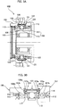
- FIG. 2A is a schematic sectional view showing an example of a lubricant-mixing-prevention part having this configuration.
- An annular oil seal 14 is secured to the external peripheral surface of a cylinder part 8b formed on the internal peripheral edge portion of the partitioning plate 8.
- a seal lip 14a of the oil seal 14 is in contact with the internal peripheral surface of the cylindrical extension portion 37 of the externally toothed gear 3.
- the oil seal 14 is provided with deformability capable of following deformation of the cylindrical extension portion 37 of the externally toothed gear 3, and each portion in the circumferential direction is ) constantly kept in a state of contact with the internal peripheral surface of the cylindrical extension portion 37.
- FIG. 2B is a schematic half-sectional view of an example of a lubricant-mixing-prevention part in which an oil seal is not used.
- the length of the cylindrical extension portion 37 is set, as appropriate, and the ) gap dimension between the open end 34 and the partitioning plate 8 is set, as appropriate. Mixing of lubricants can thereby be suppressed to a level that does not hinder practical use. Mixing of the two lubricants can be essentially prevented by a very simple lubricant-mixing-prevention part.
- FIG. 2C is a schematic half-sectional view showing an example in which a labyrinth seal is used as the lubricant-mixing-prevention part.
- An annular groove 8c having a rectangular cross section is formed on the facing surface 8a of the partitioning plate 8 that faces the open end 34 of the cylindrical extension portion 37 of the externally toothed gear 3.
- a state is formed in which a portion of the open end 34 of ) the cylindrical extension portion 37 is inserted into the groove 8c.
- the width of the groove 8c is set to a dimension in which there is no interference with the portion of the open end 34 even if the portion deforms.
- a labyrinth seal is formed between the internal peripheral surface of the groove 8c and the external peripheral surface portion of the portion of the open end 34 of the cylindrical extension portion 37. Mixing of lubricants with each other can be reliably prevented by a lubricant-mixing-prevention part configured from the cylindrical extension portion 37 and a labyrinth seal.
- FIG. 3A is a schematic cross-sectional view showing the strain wave gearing according to a second embodiment in which the present invention has been applied
- FIG. 3B is an enlarged cross-sectional view showing a portion thereof.
- the strain wave gearing 100 is a flat-type strain wave gearing, and is provided with rigid first and second internally toothed gears 101 and 102 disposed in parallel, a cylindrically shaped flexible externally toothed gear 103 disposed on the inner side thereof, and a hollow wave generator 104 disposed on the inner side of the externally toothed gear 103.
- a motor 105 is coaxially accommodated in the hollow part of the wave generator 104.
- the first and second internally toothed gears 101, 102 are supported by a cross roller bearing 106 so as to allow rotation relative to each other, and the first internally toothed gear 101 is secured to the device housing 107.
- An annular output shaft part 108 is integrally formed on the second internally toothed gear 102.
- the wave generator 104 is provided with a rigid cam plate portion 110 integrally formed on the motor rotor 109, and a wave bearing 111 mounted on an ellipsoidal external peripheral surface of the rigid cam plate portion 110. Ball bearings 112, 113 are disposed on both sides of the wave bearing 111.
- the motor rotor 109 is supported by the device housing 107 and the ) output shaft part 108 via the ball bearings 112, 113.
- the externally toothed gear 103 is ellipsoidally flexed by the wave generator 104 and meshes with the first and second internally toothed gears 101, 102.
- the rigid cam plate portion 110 which is integrally formed therewith, also rotates, and the meshing position of the externally toothed gear 103 with the first and second internally toothed gears 101, 102 also moves in the circumferential direction.
- the second internally toothed gear 102 and the externally toothed gear 103 have the same number I of teeth.
- the number of teeth of the first internally toothed gear 101 on the secured side is two greater than the number of teeth of the gears 102, 103.
- the tooth meshing portion between the externally toothed gear 103 and the first and second internally toothed gears 101, 102 positioned on the outer side of the externally toothed gear 103 is the outer-side lubrication portion 121 which is lubricated by a lubricant.
- the sliding portions in the wave generator 104 positioned on the inner side of the externally toothed gear 103, and the contact portion between the wave generator 104 and the externally toothed gear 103, are the inner-side lubrication portion 122 which is ) lubricated by a lubricant of a type different from the lubricant used in the tooth meshing portion.
- the strain wave gearing 100 is provided with a lubricant-mixing-prevention part for preventing the lubricant supplied to the outer-side lubrication portion 121 and the lubricant supplied to the inner-side ) lubrication portion 122 from inter-mixing.
- annular first and second oil seals 123, 124 that seal off the area between the outer-side lubrication portion 121 and the inner-side lubrication portion 122 are disposed as the lubricant-mixing-prevention part.
- the internal peripheral edge of the end face 107a is connected to a circular internal peripheral surface 107b, and an outer race 114 of the ball bearing 112 is secured to the circular internal peripheral surface 107b.
- the first oil seal 123 is secured to an end face 115 of the outer race 114 on the wave generator 104 side.
- a seal lip 123a of the first oil seal 123 is in contact with the internal peripheral surface portion of the externally toothed gear 103 on the first open end 103a side.
- the internal peripheral edge of the end face 108a is connected to a circular internal peripheral surface 108b, and an outer race 116 of the ball bearing 113 is secured to the circular internal peripheral surface 108b.
- the I second oil seal 124 is secured to an end face 117 of the outer race 116 on the wave generator 104 side.
- a seal lip 124a of the second oil seal 124 is in contact with the internal peripheral surface portion of the externally toothed gear on the second open end 103b side.
- the strain wave gearing 100 is provided with rigid first and second internally toothed gears, a cylindrically shaped flexible externally toothed gear, and a wave generator.
- the first and second internally toothed gears are disposed in parallel on the outer side of the externally toothed gear, and the wave generator is disposed on the inner side of the externally toothed gear.
- the strain wave gearing 100 has an inner-side lubrication portion on the inner side of the externally toothed gear, an outer-side lubrication portion on the outer side of the externally toothed gear, and a lubricant-mixing-prevention part for preventing a lubricant for lubricating the inner-side lubrication portion and a lubricant for lubricating the outer-side lubrication portion from inter-mixing.
- the inner-side lubrication portion includes sliding portions of the wave generator and a contact portion between the wave generator and the internal peripheral surface of the externally toothed gear, and the outer-side lubrication portion is the tooth meshing portion between the externally toothed gear and the first and second internally toothed gears.
- First and second oil seals which seal off the area between the inner-side lubrication portion and the outer-side lubrication portion, are provided as the lubricant-mixing-prevention part.
- the first oil seal is secured to the first internally toothed gear, or is secured to a member which is secured to the first internally toothed gear.
- the seal lip of the first oil seal is in contact with the internal peripheral surface of the externally toothed gear.
- the second oil seal is secured to the second internally toothed gear, or is secured to a member which is secured to the second internally toothed gear.
- the seal lip of the second oil seal is secured to the internal peripheral surface of the externally toothed gear.
- the first and second oil seals 123, 124 are provided with a deforming property enabling the deformation of the externally toothed gear 3 to be followed, so that each portion in the circumferential direction is constantly kept in a state of contact with the internal peripheral surface of the externally toothed gear 3. Lubricants can be reliably prevented by the first and second oil seals 123, 124 from mixing together, and both the outer-side lubrication portion 121 and the inner-side lubrication portion 122 can be kept in an appropriately lubricated state.
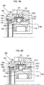
- the oil seals 123, 124 can be omitted.
- the internal peripheral surface portion of the externally toothed gear 103 on both sides of the wave bearing 111 is narrow, and the oil seals 123, 124 cannot be disposed in the externally toothed gear 103.
- the externally toothed gear 103A there are formed a first cylindrical extension portion 131 and a second cylindrical extension portion 132, which extend a predetermined length without external teeth from the ends, respectively, on both sides of the cylindrical external tooth formation portion in which external teeth are formed.
- Seal lips 123a, 124a of the first and second oil seals 123, 124 are caused to be in contact with the internal peripheral surfaces of the first and second cylindrical extension portions 131, 132, respectively.
- Lubricants can be reliably prevented from inter-mixing by the lubricant-mixing-prevention part provided with the first and second oil seals 123, 124 and the first and second cylindrical extension portions 131, 132, and both the outer-side lubrication portion 121 and the inner-side lubrication portion 122 can be kept in an appropriately lubricated state.
- a labyrinth seal can be used in lieu of an oil seal as a lubricant-mixing-prevention structure.
- the end face 107a of the device housing 107 faces a first open end 131a, which is an open end of the first cylindrical extension portion 131 of the externally toothed gear 103A.
- An annular groove 107c having a rectangular cross section is formed on the end face 107a.
- a portion of the first open end 131a of the first cylindrical extension portion 131 is inserted into the groove 107c.
- the open width of the groove 107c is of such a dimension as to prevent interference with deformation of the first cylindrical extension portion 131.
- a first labyrinth seal is formed between the groove 107c and a portion of the first open end 131a of the first cylindrical extension portion 131.
- the end face 108a of the output shaft part 108 faces a second open end 132a, which is an open end of the second cylindrical extension portion 132 of the externally toothed gear 103A.
- An annular groove 108c having a rectangular cross section is formed on the end face 108a.
- a state is formed in which a portion of the second open end 132a of the second cylindrical extension portion 132 is inserted into the groove 108c.
- the open width of the groove 108c is set to a dimension in which there is no interference with deformation of the second cylindrical extension portion 132.
- a second labyrinth seal is formed between the groove 108c and a portion of the second cylindrical extension portion 132.
- Lubricants can be reliably prevented from inter-mixing by a lubricant-mixing-prevention structure provided with first and second labyrinth seals, and both the outer-side lubrication portion 121 and the inner-side lubrication portion 122 can be kept in an appropriately lubricated state.
Abstract
Description
- The present invention relates to a strain wave gearing, and more particularly relates to a strain wave gearing provided with a lubricant-mixing-prevention part for preventing the inter-mixing of a lubricant supplied to a tooth meshing portion on the outer side of an externally toothed gear and a lubricant of a different type supplied to a portion of a wave generator on the inner side of the externally toothed gear.
- Strain wave gearings have an inner-side lubrication portion positioned on the inner side of an externally toothed gear, and an outer-side lubrication portion positioned on the outer side of an externally toothed gear. The inner-side lubrication portion includes sliding portions in the wave generator and a sliding portion between the wave generator and the internal peripheral surface of the externally toothed gear, and the outer-side lubrication portion is the tooth meshing portion between the externally toothed gear and the internally toothed gear. Optimal lubricants differ for the inner-side lubrication portion and the outer-side lubrication portion, and therefore, lubricants having respectively different lubricating properties are preferably supplied. However, the inner-side lubrication portion and the outer-side lubrication portion are located in nearby positions inside and outside the externally toothed gear, and therefore the two lubricants mix together. Accordingly, the same type of lubricant is often used in both ) lubrication portions, and there are problems such as reduced efficiency, and abrasion of the tooth meshing portion during a high load.
- In the flat-type strain wave gearing described in
Patent Document 1, a ring-shaped seal member is disposed on both sides I of a cylindrical externally toothed gear, and the space between the inner-side lubrication portion and the outer-side lubrication portion is blocked to prevent mixing of different types of lubricant. In the strain wave gearing described inPatent Document 2, a seal member is disposed at an opening end of an externally toothed gear to prevent mixing of lubricants. In the strain wave gearing described inPatent Document 3, an elastic seal is sandwiched between an externally toothed gear and a secure member to prevent mixing of lubricants. -
- Patent Document 1:
JP 2017-96343 A - Patent Document 2:
JP H09-291985 A - Patent Document 3:
JP H09-250609 A - An object of the present invention is to provide a strain wave gearing provided with a lubricant-mixing-prevention part that can suppress, to a level that does not impede practical use, the inter-mixing of lubricant supplied to an inner-side lubrication portion and lubricant supplied to an outer-side lubrication portion.
- Another object of the present invention is to provide a strain wave gearing provided with a lubricant-mixing-prevention part that can effectively prevent inter-mixing of the lubricant supplied to the inner-side lubrication portion and the lubricant supplied to the outer-side lubrication portion.
- The strain wave gearing of the present invention has a rigid internally toothed gear, a flexible externally toothed gear having a cup shape or a top hat shape, a wave generator, an inner-side lubrication portion on an inner side of the externally toothed gear, an outer-side lubrication portion on an outer side of the externally toothed gear, and a lubricant-mixing-prevention part for preventing a lubricant that lubricates the inner-side lubrication portion and a lubricant that lubricates the outer-side lubrication portion from inter-mixing. The externally toothed gear is provided with a cylindrical barrel part, a diaphragm extending radially inward or outward from one end of the cylindrical barrel part, and an open end, which is the other end of the cylindrical barrel part. The cylindrical barrel part is provided with an external tooth formation portion on which external teeth are formed, and a cylindrical extension portion between the end of the external tooth formation portion and the opening end. The internally toothed gear is disposed so as to surround the external tooth formation portion, and the wave generator is disposed on the inner side of the external tooth formation portion, flexing the external tooth formation portion into a non-circular shape to cause the externally toothed gear to partially mesh with internally toothed gear. The inner-side lubrication portion includes sliding portions in the wave generator and the contact portion between the wave generator and the internal peripheral surface of the externally toothed gear. The outer-side lubrication portion is the tooth meshing portion between the externally toothed gear and the internally toothed ) gear. The cylindrical extension portion functions as the lubrication-mixing-prevention part.
- According to the present invention, in the externally toothed gear having the profile of a cup or top hat, the end of the external tooth formation portion is extended to form the ) cylindrical extension portion. The distance from the outer-side lubrication portion (tooth meshing portion) on the outer side of the externally toothed gear to the inner-side lubrication portion on the inner side of the externally toothed gear is increased by the length of the cylindrical extension portion. Appropriately ) setting the length of the cylindrical extension portion in accordance with, inter alia, the viscosity of the supplied lubricant makes it possible to suppress mixing of the two lubricants to a level that does not impede practical use. Mixing of lubricants can be suppressed without attaching a seal member or other components.
- In order to effectively prevent the lubricants from mixing together, the space between the inner-side lubrication portion and the outer-side lubrication portion can be sealed using an oil seal. The oil seal can be directly secured to the internally toothed gear, or can be secured to a member secured to the internally toothed gear. Moreover, in the externally toothed gear, the external peripheral surface or the internal peripheral surface of the cylindrical extension portion can be the site where the seal lip of the oil seal is allowed to be brought into contact.
- In lieu of an oil seal, it is possible to form a labyrinth seal between the cylindrical extension portion and a facing member that faces the cylindrical extension portion to prevent lubricant from circulating between the inner-side lubrication portion and the outer-side lubrication portion.
- The present invention can similarly be applied to a flat-type strain wave gearing. In such instances, it is possible to form a cylindrical extension portion at both ends of the cylindrical externally toothed gear, the cylindrical extension portion making it difficult for lubricant to circulate between the inner-side lubrication portion and the outer-side lubrication portion.
- It is also possible to prevent lubricant from circulating between the inner-side lubrication portion and the outer-side lubrication portion by using an oil seal or a labyrinth seal.
- Furthermore, in a flat-type strain wave gearing, there are cases in which the portion of the internal peripheral surface that can be in contact with the seal lip of the oil seal can be ensured on both sides of the wave generator in the externally toothed gear. In such cases, the cylindrical extension portion can be omitted.
-
-
FIG. 1 is a schematic cross-sectional view of a cup-type strain wave gearing according to the first embodiment of the present invention; -
FIG. 2A is a schematic cross-sectional view showing a modification of the lubricant-mixing-prevention part of the strain wave gearing ofFIG. 1 ; -
FIG. 2B is a schematic half-sectional view showing a modification of the lubricant-mixing-prevention part of the strain wave gearing ofFIG. 1 ; -
FIG. 2C is a schematic half-sectional view showing a modification of the lubricant-mixing-prevention part of the strain wave gearing ofFIG. 1 ; -
FIG. 3A is a schematic cross-sectional view of a flat-type strain wave gearing according to the second embodiment of the present invention; -
FIG. 3B is an enlarged partial sectional view showing part of the strain wave gearing ofFIG. 3A ; -
FIG. 4A is a schematic half-sectional view showing a modification of the lubricant-mixing-prevention part of the strain wave gearing ofFIG. 3A ; and -
FIG. 4B is a schematic half-sectional view showing a modification of the lubricant-mixing-prevention part of the strain wave gearing ofFIG. 3A . - Embodiments of the present invention are described below with reference to the drawings. Following are embodiments of the present invention applied to a lubricating structure of a cup-type or flat-type strain wave gearing. The present invention can be applied to a top-hat-type strain wave gearing in similar fashion to the case of a cup-type strain wave gearing.
-
FIG. 1 is a schematic cross-sectional view of a cup-type strain wave gearing according to a first embodiment of the ) present invention. Thestrain wave gearing 1 is provided with a rigid internallytoothed gear 2 having an annular shape, a flexible externallytoothed gear 3 having the profile of a cup disposed on the inner side of the internallytoothed gear 2, and awave generator 4 disposed on the inner side of the externallytoothed gear 3. The internallytoothed gear 2 is coaxially secured to the internal peripheral portion of acylindrical device housing 5. - The externally
toothed gear 3 is provided with acylindrical barrel part 31, adiaphragm 32 extending radially inward from one end of thecylindrical barrel part 31, and a rigidannular boss 33 formed in continuous fashion on the internal peripheral edge of the diaphragm. The externallytoothed gear 3 has an externaltooth formation portion 36, on which are formedexternal teeth 35, formed on thecylindrical barrel part 31, on the side nearer to anopen end 34, which is the other end of thecylindrical barrel part 31. In thecylindrical barrel part 31, the area from anend 36a of the externaltooth formation portion 36 to theopen end 34 constitutes acylindrical extension portion 37 in which external teeth are not formed. The internallytoothed gear 2 is disposed so as to surround the externaltooth formation portion 36. Thewave generator 4 is disposed on the inner side of the externaltooth formation portion 36. Adiscoid output shaft 6 is coupled and secured to theboss 33 of the externallytoothed gear 3. - The
wave generator 4 is provided with acylindrical hub 41, arigid cam plate 43 coaxially attached to the external peripheral surface of thehub 41 via anOldham coupling mechanism 42, and awave bearing 44. Thewave bearing 44 is mounted between the internal peripheral surface of the externaltooth formation portion 36 of the externallytoothed gear 3 and an ellipsoidal externalperipheral surface 43a of therigid cam plate 43. The externaltooth formation portion 36 is ellipsoidally flexed by thewave generator 4. The externallytoothed gear 3 thereby meshes with the internallytoothed gear 2 at both ends of a long axis of an ellipsoid. A rotating motor-shaft or otherrotation input shaft 7 is coaxially coupled and secured to thehub 41. - When the
wave generator 4 is rotated by therotation input shaft 7, the meshing position of bothgears gears toothed gear 2 is secured, and a reduced rotation is outputted from the externallytoothed gear 3 via theoutput shaft 6. - A
partitioning plate 8 for partitioning off the motor and other components on the rotation input side is secured to anend face 5a of thedevice housing 5. Thepartitioning plate 8 is provided with a facingsurface 8a that faces theopen end 34 of the externallytoothed gear 3, and the space between the internal peripheral surface of thepartitioning plate 8 and therotation input shaft 7 is sealed by a seal member. - In the strain wave gearing 1, the tooth meshing portion of the teeth of the externally
toothed gear 3 and the internallytoothed gear 2 positioned on the outer side of the externallytoothed gear 3 is an outer-side lubrication portion 11 which is lubricated by a lubricant. The sliding portions in thewave generator 4 positioned on the inner side of the externallytoothed gear 3, and the contact portion between the wave )generator 4 and the externallytoothed gear 3, are the inner-side lubrication portion 12 which is lubricated by a lubricant of a type different from the lubricant supplied to the tooth meshing portion. The strain wave gearing 1 is provided with a lubricant-mixing-prevention part for preventing the lubricant supplied to the outer-side lubrication portion 11 and the lubricant supplied to the inner-side lubrication portion 12 from inter-mixing. The lubricant-mixing-prevention part of the present example is configured from thecylindrical extension portion 37 formed on the externallytoothed gear 3, and anannular oil seal 13. - The
cylindrical extension portion 37 is a portion from anend 36a to theopen end 34 in the tooth-trace direction of the external teeth in the externaltooth formation portion 36 of the externallytoothed gear 3. Theoil seal 13 is secured to a portion on the internal peripheral edge side of the internallytoothed gear 2. Aseal lip 13a of theoil seal 13 is in contact with the external peripheral surface of thecylindrical extension portion 37. The area between the outer-side lubrication portion 11 and the inner-side lubrication portion 12 is sealed by theoil seal 13. Theoil seal 13 is provided with deformability capable of following deformation of thecylindrical extension portion 37 of the externallytoothed gear 3, and each portion in the circumferential direction is constantly kept in a state of ) contact with thecylindrical extension portion 37. - The lubricant supplied to the outer-
side lubrication portion 11 is blocked by theoil seal 13 from flowing out to theopen end 34 side. The lubricant supplied to the inner-side lubrication portion 12 flows out to the external peripheral side of the externallytoothed gear 3 by way of a gap portion between thecylindrical extension portion 37 and thepartitioning plate 8. Outflow to the external peripheral side of the externallytoothed gear 3 is suppressed by thecylindrical extension portion 37. Lubricant that has flowed out to the external peripheral side is ) blocked by theoil seal 13 from flowing into the outer-side lubrication portion 11. The two lubricants can be reliably prevented from mixing together, and both the outer-side lubrication portion 11 and the inner-side lubrication portion 12 can be kept in an appropriately lubricated state. - Here, the oil seal can be disposed on the inner-
side lubrication portion 12 side.FIG. 2A is a schematic sectional view showing an example of a lubricant-mixing-prevention part having this configuration. Anannular oil seal 14 is secured to the external peripheral surface of acylinder part 8b formed on the internal peripheral edge portion of thepartitioning plate 8. Aseal lip 14a of theoil seal 14 is in contact with the internal peripheral surface of thecylindrical extension portion 37 of the externallytoothed gear 3. In this case as well, theoil seal 14 is provided with deformability capable of following deformation of thecylindrical extension portion 37 of the externallytoothed gear 3, and each portion in the circumferential direction is ) constantly kept in a state of contact with the internal peripheral surface of thecylindrical extension portion 37. - There are also cases in which the oil seals 13, 14 can be omitted. For example, when the lubricants are provided with a ) property that makes mixing with each other difficult, the oil seals can be omitted.
FIG. 2B is a schematic half-sectional view of an example of a lubricant-mixing-prevention part in which an oil seal is not used. In this case, the length of thecylindrical extension portion 37 is set, as appropriate, and the ) gap dimension between theopen end 34 and thepartitioning plate 8 is set, as appropriate. Mixing of lubricants can thereby be suppressed to a level that does not hinder practical use. Mixing of the two lubricants can be essentially prevented by a very simple lubricant-mixing-prevention part. -
FIG. 2C is a schematic half-sectional view showing an example in which a labyrinth seal is used as the lubricant-mixing-prevention part. Anannular groove 8c having a rectangular cross section is formed on the facingsurface 8a of thepartitioning plate 8 that faces theopen end 34 of thecylindrical extension portion 37 of the externallytoothed gear 3. A state is formed in which a portion of theopen end 34 of ) thecylindrical extension portion 37 is inserted into thegroove 8c. The width of thegroove 8c is set to a dimension in which there is no interference with the portion of theopen end 34 even if the portion deforms. A labyrinth seal is formed between the internal peripheral surface of thegroove 8c and the external peripheral surface portion of the portion of theopen end 34 of thecylindrical extension portion 37. Mixing of lubricants with each other can be reliably prevented by a lubricant-mixing-prevention part configured from thecylindrical extension portion 37 and a labyrinth seal. -
FIG. 3A is a schematic cross-sectional view showing the strain wave gearing according to a second embodiment in which the present invention has been applied, andFIG. 3B is an enlarged cross-sectional view showing a portion thereof. The strain wave gearing 100 is a flat-type strain wave gearing, and is provided with rigid first and second internallytoothed gears toothed gear 103 disposed on the inner side thereof, and ahollow wave generator 104 disposed on the inner side of the externallytoothed gear 103. Amotor 105 is coaxially accommodated in the hollow part of thewave generator 104. - The first and second internally
toothed gears cross roller bearing 106 so as to allow rotation relative to each other, and the first internallytoothed gear 101 is secured to thedevice housing 107. An annularoutput shaft part 108 is integrally formed on the second internallytoothed gear 102. Thewave generator 104 is provided with a rigidcam plate portion 110 integrally formed on themotor rotor 109, and a wave bearing 111 mounted on an ellipsoidal external peripheral surface of the rigidcam plate portion 110.Ball bearings wave bearing 111. Themotor rotor 109 is supported by thedevice housing 107 and the )output shaft part 108 via theball bearings - The externally
toothed gear 103 is ellipsoidally flexed by thewave generator 104 and meshes with the first and second internallytoothed gears motor 105 is driven and themotor rotor 109 rotates, the rigidcam plate portion 110, which is integrally formed therewith, also rotates, and the meshing position of the externallytoothed gear 103 with the first and second internallytoothed gears toothed gear 102 and the externallytoothed gear 103 have the same number I of teeth. The number of teeth of the first internallytoothed gear 101 on the secured side is two greater than the number of teeth of thegears strain wave generator 104 rotates, a relative rotation corresponding to the difference in the number of teeth is generated between the first internallytoothed gear 101 and the externallytoothed gear 103. This rotation is outputted from the second internallytoothed gear 102 via theoutput shaft part 108. - In the strain wave gearing 100, the tooth meshing portion between the externally
toothed gear 103 and the first and second internallytoothed gears toothed gear 103 is the outer-side lubrication portion 121 which is lubricated by a lubricant. The sliding portions in thewave generator 104 positioned on the inner side of the externallytoothed gear 103, and the contact portion between thewave generator 104 and the externallytoothed gear 103, are the inner-side lubrication portion 122 which is ) lubricated by a lubricant of a type different from the lubricant used in the tooth meshing portion. The strain wave gearing 100 is provided with a lubricant-mixing-prevention part for preventing the lubricant supplied to the outer-side lubrication portion 121 and the lubricant supplied to the inner-side )lubrication portion 122 from inter-mixing. In the present example, annular first and second oil seals 123, 124 that seal off the area between the outer-side lubrication portion 121 and the inner-side lubrication portion 122 are disposed as the lubricant-mixing-prevention part. - An
end face 107a that faces a first open end 103a, which is one open end of the externallytoothed gear 103, is formed on thedevice housing 107 in which the first internallytoothed gear 101 is formed. The internal peripheral edge of theend face 107a is connected to a circular internalperipheral surface 107b, and anouter race 114 of theball bearing 112 is secured to the circular internalperipheral surface 107b. Thefirst oil seal 123 is secured to anend face 115 of theouter race 114 on thewave generator 104 side. Aseal lip 123a of thefirst oil seal 123 is in contact with the internal peripheral surface portion of the externallytoothed gear 103 on the first open end 103a side. - An
end face 108a that faces a secondopen end 103b, which is the other open end of the externallytoothed gear 103, is formed on theoutput shaft part 108 on which the second internallytoothed gear 102 is formed. The internal peripheral edge of theend face 108a is connected to a circular internalperipheral surface 108b, and anouter race 116 of theball bearing 113 is secured to the circular internalperipheral surface 108b. The Isecond oil seal 124 is secured to anend face 117 of theouter race 116 on thewave generator 104 side. Aseal lip 124a of thesecond oil seal 124 is in contact with the internal peripheral surface portion of the externally toothed gear on the secondopen end 103b side. - Thus, the strain wave gearing 100 is provided with rigid first and second internally toothed gears, a cylindrically shaped flexible externally toothed gear, and a wave generator. The first and second internally toothed gears are disposed in parallel on the outer side of the externally toothed gear, and the wave generator is disposed on the inner side of the externally toothed gear. The strain wave gearing 100 has an inner-side lubrication portion on the inner side of the externally toothed gear, an outer-side lubrication portion on the outer side of the externally toothed gear, and a lubricant-mixing-prevention part for preventing a lubricant for lubricating the inner-side lubrication portion and a lubricant for lubricating the outer-side lubrication portion from inter-mixing. The inner-side lubrication portion includes sliding portions of the wave generator and a contact portion between the wave generator and the internal peripheral surface of the externally toothed gear, and the outer-side lubrication portion is the tooth meshing portion between the externally toothed gear and the first and second internally toothed gears. First and second oil seals, which seal off the area between the inner-side lubrication portion and the outer-side lubrication portion, are provided as the lubricant-mixing-prevention part. The first oil seal is secured to the first internally toothed gear, or is secured to a member which is secured to the first internally toothed gear. The seal lip of the first oil seal is in contact with the internal peripheral surface of the externally toothed gear. The second oil seal is secured to the second internally toothed gear, or is secured to a member which is secured to the second internally toothed gear. The seal lip of the second oil seal is secured to the internal peripheral surface of the externally toothed gear.
- The first and second oil seals 123, 124 are provided with a deforming property enabling the deformation of the externally
toothed gear 3 to be followed, so that each portion in the circumferential direction is constantly kept in a state of contact with the internal peripheral surface of the externallytoothed gear 3. Lubricants can be reliably prevented by the first and second oil seals 123, 124 from mixing together, and both the outer-side lubrication portion 121 and the inner-side lubrication portion 122 can be kept in an appropriately lubricated state. - Here, in the case of two types of lubricants that do not easily intermix, the oil seals 123, 124 can be omitted. There are some cases in which the internal peripheral surface portion of the externally
toothed gear 103 on both sides of the wave bearing 111 is narrow, and the oil seals 123, 124 cannot be disposed in the externallytoothed gear 103. In such cases, as shown inFIG. 4A , on the externallytoothed gear 103A there are formed a firstcylindrical extension portion 131 and a secondcylindrical extension portion 132, which extend a predetermined length without external teeth from the ends, respectively, on both sides of the cylindrical external tooth formation portion in which external teeth are formed.Seal lips cylindrical extension portions - Lubricants can be reliably prevented from inter-mixing by the lubricant-mixing-prevention part provided with the first and second oil seals 123, 124 and the first and second
cylindrical extension portions side lubrication portion 121 and the inner-side lubrication portion 122 can be kept in an appropriately lubricated state. - A labyrinth seal can be used in lieu of an oil seal as a lubricant-mixing-prevention structure. As shown in
FIG. 4B , in the strain wave gearing 100, theend face 107a of thedevice housing 107 faces a firstopen end 131a, which is an open end of the firstcylindrical extension portion 131 of the externallytoothed gear 103A. Anannular groove 107c having a rectangular cross section is formed on theend face 107a. A portion of the firstopen end 131a of the firstcylindrical extension portion 131 is inserted into thegroove 107c. The open width of thegroove 107c is of such a dimension as to prevent interference with deformation of the firstcylindrical extension portion 131. A first labyrinth seal is formed between thegroove 107c and a portion of the firstopen end 131a of the firstcylindrical extension portion 131. - Similarly, the
end face 108a of theoutput shaft part 108 faces a secondopen end 132a, which is an open end of the secondcylindrical extension portion 132 of the externallytoothed gear 103A. Anannular groove 108c having a rectangular cross section is formed on theend face 108a. A state is formed in which a portion of the secondopen end 132a of the secondcylindrical extension portion 132 is inserted into thegroove 108c. The open width of thegroove 108c is set to a dimension in which there is no interference with deformation of the secondcylindrical extension portion 132. A second labyrinth seal is formed between thegroove 108c and a portion of the secondcylindrical extension portion 132. - Lubricants can be reliably prevented from inter-mixing by a lubricant-mixing-prevention structure provided with first and second labyrinth seals, and both the outer-
side lubrication portion 121 and the inner-side lubrication portion 122 can be kept in an appropriately lubricated state.
Claims (6)
- A strain wave gearing comprising:a rigid internally toothed gear;a flexible externally toothed gear having a cup shape or top hat shape;a wave generator;an inner-side lubrication portion on an inner side of the externally toothed gear;an outer-side lubrication portion on an outer side of the externally toothed gear; anda lubricant-mixing-prevention part for preventing a lubricant that lubricates the inner-side lubrication portion and a lubricant that lubricates the outer-side lubrication portion from inter-mixing,wherein the externally toothed gear has: a cylindrical barrel part; a diaphragm extending radially inward or outward from one end of the cylindrical barrel part; and an open end, which is the other end of the cylindrical barrel part,the cylindrical barrel part has: an external tooth formation portion on which external teeth are formed; and a cylindrical extension portion between an end of the external tooth formation portion and the opening end,the internally toothed gear is disposed so as to surround the external tooth formation portion,the wave generator is disposed on an inner side of the external tooth formation portion, flexing the external tooth formation portion into a non-circular shape to cause the externally toothed gear to partially mesh with internally toothed gear,the inner-side lubrication portion includes sliding portions in the wave generator and a contact portion between the wave generator and an internal peripheral surface of the externally toothed gear,the outer-side lubrication portion is a tooth meshing portion between the externally toothed gear and the internally toothed gear, andthe lubrication-mixing-prevention part comprises the cylindrical extension portion.
- The strain wave gearing according to claim 1, wherein
the lubricant-mixing -prevention part further comprises an oil seal for sealing an area between the inner-side lubrication portion and the outer-side lubrication portion,
the oil seal is secured to the internally toothed gear, or is secured to a member secured to the internally toothed gear, and
the oil seal has a seal lip is in contact with an external peripheral surface or internal peripheral surface of the cylindrical extension portion of the externally toothed gear. - The strain wave gearing according to claim 1, further comprising:a facing member that faces the open end of the cylindrical extension portion,wherein the facing member has an annular groove where the open end of the cylindrical extension portion is inserted, anda labyrinth seal is formed between the cylindrical extension portion and the annular groove.
- A strain wave gearing having rigid first and second internally toothed gears, a cylindrically shaped flexible externally toothed gear, and a wave generator, the first and second internally toothed gear being disposed in parallel on a radially outer side of the externally toothed gear, the wave generator being disposed on a radially inner side of the externally toothed gear, the strain wave gearing comprising:an inner-side lubrication portion on an inner side of the externally toothed gear;an outer-side lubrication portion on an outer side of the externally toothed gear; anda lubricant-mixing-prevention part for preventing a lubricant that lubricates the inner-side lubrication portion and a lubricant that lubricates the outer-side lubrication portion from inter-mixing,wherein the inner-side lubrication portion includes sliding portions in the wave generator and a contact portion between the wave generator and an internal peripheral surface of the externally toothed gear,the outer-side lubrication portion is a tooth meshing portion between the externally toothed gear and the first and second internally toothed gears,the externally toothed gear has: a cylindrical externa tooth formation portion where external teeth are formed, a first cylindrical extension portion, and a second cylindrical extension portion, wherein the first and second cylindrical extensions are not formed with the external teeth and extend in a tooth trace direction by a prescribed length from both side ends of the external tooth forming portion, andthe lubrication-mixing-prevention part comprises the first and second cylindrical extension portions.
- The strain wave gearing according to claim 4, wherein
the lubricant-mixing -prevention part further comprises first and second oil seals for sealing an area between the inner-side lubrication portion and the outer-side lubrication portion,
the first oil seal is secured to the first internally toothed gear, or is secured to a first member secured to the first internally toothed gear, wherein the first oil seal has a seal lip in contact with an external peripheral surface or internal peripheral surface of the first cylindrical extension portion, and
the second oil seal is secured to the second internally toothed gear, or is secured to a second member secured to the second internally toothed gear, wherein second oil seal has a seal lip in contact with an external peripheral surface or internal peripheral surface of the second cylindrical extension portion. - The strain wave gearing according to claim 4, further comprising:a first facing member that faces a first open end of the first cylindrical extension portion, anda second facing member that faces a second open end of the second cylindrical extension portion,wherein the first facing member has a first annular groove where the first open end of the first cylindrical extension portion is inserted,the second facing member has a second annular groove where the second open end of the second cylindrical extension portion is inserted,a first labyrinth seal is formed between the first cylindrical extension portion and the first annular groove, anda second labyrinth seal is formed between the second cylindrical extension portion and the second annular groove.
Applications Claiming Priority (1)
| Application Number | Priority Date | Filing Date | Title |
|---|---|---|---|
| PCT/JP2017/029830 WO2019038817A1 (en) | 2017-08-21 | 2017-08-21 | Wave motion gear device provided with lubricant mixing prevention part |
Publications (3)
| Publication Number | Publication Date |
|---|---|
| EP3674579A1 true EP3674579A1 (en) | 2020-07-01 |
| EP3674579A4 EP3674579A4 (en) | 2021-03-17 |
| EP3674579B1 EP3674579B1 (en) | 2022-10-26 |
Family
ID=65439432
Family Applications (1)
| Application Number | Title | Priority Date | Filing Date |
|---|---|---|---|
| EP17922218.7A Active EP3674579B1 (en) | 2017-08-21 | 2017-08-21 | Wave motion gear device provided with lubricant mixing prevention part |
Country Status (7)
| Country | Link |
|---|---|
| US (1) | US11118669B2 (en) |
| EP (1) | EP3674579B1 (en) |
| JP (1) | JP6739888B2 (en) |
| KR (1) | KR102269120B1 (en) |
| CN (1) | CN110998139B (en) |
| TW (1) | TWI770208B (en) |
| WO (1) | WO2019038817A1 (en) |
Families Citing this family (4)
| Publication number | Priority date | Publication date | Assignee | Title |
|---|---|---|---|---|
| JP2020034128A (en) * | 2018-08-31 | 2020-03-05 | セイコーエプソン株式会社 | Gear device, gear device unit and robot |
| JP7401990B2 (en) | 2019-08-07 | 2023-12-20 | Ntn株式会社 | ball bearing |
| JP2022032789A (en) * | 2020-08-14 | 2022-02-25 | セイコーエプソン株式会社 | Gear device and robot |
| JP2022077275A (en) * | 2020-11-11 | 2022-05-23 | セイコーエプソン株式会社 | Drive unit and assembling method of drive unit |
Family Cites Families (17)
| Publication number | Priority date | Publication date | Assignee | Title |
|---|---|---|---|---|
| DE2434834C2 (en) * | 1974-07-19 | 1985-07-25 | Werner Dr.-Ing. 2000 Hamburg Ohm | Gear motor |
| JPS59113343A (en) * | 1982-12-20 | 1984-06-30 | Matsushita Electric Ind Co Ltd | Reduction gear |
| JPS6057058A (en) * | 1983-09-05 | 1985-04-02 | Haamonitsuku Drive Syst:Kk | Lubricating oil seal device of harmonic gear device |
| SU1321962A2 (en) * | 1985-02-11 | 1987-07-07 | Военный Инженерный Краснознаменный Институт Им.А.Ф.Можайского | Wave gearing |
| JP2901424B2 (en) * | 1992-08-06 | 1999-06-07 | 住友重機械工業株式会社 | Low speed geared motor |
| JPH0942466A (en) * | 1995-07-28 | 1997-02-14 | Suzuki Motor Corp | Oil seal structure on drive shaft |
| JP3781312B2 (en) * | 1996-03-18 | 2006-05-31 | 株式会社ハーモニック・ドライブ・システムズ | Lubrication mechanism of flexure mesh gear system |
| JP3788526B2 (en) | 1996-04-30 | 2006-06-21 | 株式会社ハーモニック・ドライブ・システムズ | Lubricant sealing mechanism for flexibly meshing gear system |
| US5984048A (en) * | 1997-09-10 | 1999-11-16 | Harmonic Drive Systems, Inc. | Lubricant supplying mechanism for a wave gear drive |
| JP2008164149A (en) * | 2007-01-04 | 2008-07-17 | Jtekt Corp | Lubricant inclusion preventing mechanism of undulating gear speed reducer and steering device with variable gear ratio |
| DE112011105253T5 (en) * | 2011-05-16 | 2014-02-13 | Harmonic Drive Systems Inc. | Unit type wave gear |
| WO2015037105A1 (en) * | 2013-09-12 | 2015-03-19 | 株式会社ハーモニック・ドライブ・システムズ | Strain wave gear device unit |
| DE102015104308A1 (en) * | 2015-03-23 | 2016-09-29 | Harmonic Drive Ag | Gearbox kit with an output bearing and a voltage wave gearbox which can be stored in it |
| CN104832622A (en) * | 2015-05-20 | 2015-08-12 | 蒋桂云 | Harmonic reducer of improved structure |
| JP2017096343A (en) | 2015-11-19 | 2017-06-01 | 住友重機械工業株式会社 | Flexing engagement type gear device |
| CN105864365B (en) * | 2016-06-16 | 2018-09-07 | 南通慧幸智能科技有限公司 | Self-lubricated harmonic speed reducer |
| CN107588177A (en) * | 2017-09-28 | 2018-01-16 | 深圳市领略数控设备有限公司 | A kind of cycloidal-pin wheel harmonic drive |
-
2017
- 2017-08-21 CN CN201780093843.2A patent/CN110998139B/en active Active
- 2017-08-21 JP JP2019537446A patent/JP6739888B2/en active Active
- 2017-08-21 KR KR1020207006093A patent/KR102269120B1/en active IP Right Grant
- 2017-08-21 WO PCT/JP2017/029830 patent/WO2019038817A1/en unknown
- 2017-08-21 US US16/633,391 patent/US11118669B2/en active Active
- 2017-08-21 EP EP17922218.7A patent/EP3674579B1/en active Active
-
2018
- 2018-06-27 TW TW107122027A patent/TWI770208B/en active
Also Published As
| Publication number | Publication date |
|---|---|
| CN110998139B (en) | 2022-09-13 |
| US20200232549A1 (en) | 2020-07-23 |
| JP6739888B2 (en) | 2020-08-12 |
| JPWO2019038817A1 (en) | 2020-07-02 |
| WO2019038817A1 (en) | 2019-02-28 |
| EP3674579A4 (en) | 2021-03-17 |
| TW201920852A (en) | 2019-06-01 |
| KR102269120B1 (en) | 2021-06-23 |
| TWI770208B (en) | 2022-07-11 |
| KR20200032740A (en) | 2020-03-26 |
| CN110998139A (en) | 2020-04-10 |
| US11118669B2 (en) | 2021-09-14 |
| EP3674579B1 (en) | 2022-10-26 |
Similar Documents
| Publication | Publication Date | Title |
|---|---|---|
| EP3674579A1 (en) | Wave motion gear device provided with lubricant mixing prevention part | |
| US11566695B2 (en) | Unit-type strain wave gearing device | |
| JP6021694B2 (en) | Wheel drive series | |
| JPH09250609A (en) | Lubricating mechanism for bendingly egaged gear device | |
| US11320041B2 (en) | Method for lubricating strain wave gearing | |
| CN114110095A (en) | Flexible engagement type gear device | |
| KR101973662B1 (en) | Reducer with an intermittent lubricating device | |
| JP2007263201A (en) | Lubricant-sealing structure in gear device | |
| JP2009287634A (en) | Gear transmission | |
| CN112443645A (en) | Motor assembly | |
| JP7482895B2 (en) | Strain Wave Gearing | |
| CN114245852A (en) | Unit type wave gear device | |
| JP2005188729A (en) | Shaft seal part structure for dip-feed lubrication type transmission gear | |
| CN209414573U (en) | Speed change gear | |
| JP2022536629A (en) | Strain wave gearing | |
| JP2004301276A (en) | Grease sealing structure of transmission | |
| JP2022105356A (en) | Deflection engagement type gear device | |
| JPH0379847A (en) | Shaft sealing device for gear roraty shaft | |
| JP2006250260A (en) | Lubricant-sealing structure in gear case |
Legal Events
| Date | Code | Title | Description |
|---|---|---|---|
| STAA | Information on the status of an ep patent application or granted ep patent |
Free format text: STATUS: THE INTERNATIONAL PUBLICATION HAS BEEN MADE |
|
| PUAI | Public reference made under article 153(3) epc to a published international application that has entered the european phase |
Free format text: ORIGINAL CODE: 0009012 |
|
| STAA | Information on the status of an ep patent application or granted ep patent |
Free format text: STATUS: REQUEST FOR EXAMINATION WAS MADE |
|
| 17P | Request for examination filed |
Effective date: 20200320 |
|
| AK | Designated contracting states |
Kind code of ref document: A1 Designated state(s): AL AT BE BG CH CY CZ DE DK EE ES FI FR GB GR HR HU IE IS IT LI LT LU LV MC MK MT NL NO PL PT RO RS SE SI SK SM TR |
|
| AX | Request for extension of the european patent |
Extension state: BA ME |
|
| DAV | Request for validation of the european patent (deleted) | ||
| DAX | Request for extension of the european patent (deleted) | ||
| A4 | Supplementary search report drawn up and despatched |
Effective date: 20210211 |
|
| RIC1 | Information provided on ipc code assigned before grant |
Ipc: F16H 57/04 20100101AFI20210205BHEP Ipc: F16H 49/00 20060101ALI20210205BHEP |
|
| REG | Reference to a national code |
Ref country code: DE Ref legal event code: R079 Ref document number: 602017063159 Country of ref document: DE Free format text: PREVIOUS MAIN CLASS: F16H0001320000 Ipc: F16H0057040000 |
|
| GRAP | Despatch of communication of intention to grant a patent |
Free format text: ORIGINAL CODE: EPIDOSNIGR1 |
|
| STAA | Information on the status of an ep patent application or granted ep patent |
Free format text: STATUS: GRANT OF PATENT IS INTENDED |
|
| RIC1 | Information provided on ipc code assigned before grant |
Ipc: F16H 49/00 20060101ALI20220428BHEP Ipc: F16H 57/04 20100101AFI20220428BHEP |
|
| INTG | Intention to grant announced |
Effective date: 20220517 |
|
| GRAS | Grant fee paid |
Free format text: ORIGINAL CODE: EPIDOSNIGR3 |
|
| GRAA | (expected) grant |
Free format text: ORIGINAL CODE: 0009210 |
|
| STAA | Information on the status of an ep patent application or granted ep patent |
Free format text: STATUS: THE PATENT HAS BEEN GRANTED |
|
| AK | Designated contracting states |
Kind code of ref document: B1 Designated state(s): AL AT BE BG CH CY CZ DE DK EE ES FI FR GB GR HR HU IE IS IT LI LT LU LV MC MK MT NL NO PL PT RO RS SE SI SK SM TR |
|
| REG | Reference to a national code |
Ref country code: GB Ref legal event code: FG4D |
|
| REG | Reference to a national code |
Ref country code: CH Ref legal event code: EP |
|
| REG | Reference to a national code |
Ref country code: AT Ref legal event code: REF Ref document number: 1527239 Country of ref document: AT Kind code of ref document: T Effective date: 20221115 |
|
| REG | Reference to a national code |
Ref country code: DE Ref legal event code: R096 Ref document number: 602017063159 Country of ref document: DE |
|
| REG | Reference to a national code |
Ref country code: IE Ref legal event code: FG4D |
|
| REG | Reference to a national code |
Ref country code: LT Ref legal event code: MG9D |
|
| REG | Reference to a national code |
Ref country code: NL Ref legal event code: MP Effective date: 20221026 |
|
| REG | Reference to a national code |
Ref country code: AT Ref legal event code: MK05 Ref document number: 1527239 Country of ref document: AT Kind code of ref document: T Effective date: 20221026 |
|
| PG25 | Lapsed in a contracting state [announced via postgrant information from national office to epo] |
Ref country code: NL Free format text: LAPSE BECAUSE OF FAILURE TO SUBMIT A TRANSLATION OF THE DESCRIPTION OR TO PAY THE FEE WITHIN THE PRESCRIBED TIME-LIMIT Effective date: 20221026 |
|
| PG25 | Lapsed in a contracting state [announced via postgrant information from national office to epo] |
Ref country code: SE Free format text: LAPSE BECAUSE OF FAILURE TO SUBMIT A TRANSLATION OF THE DESCRIPTION OR TO PAY THE FEE WITHIN THE PRESCRIBED TIME-LIMIT Effective date: 20221026 Ref country code: PT Free format text: LAPSE BECAUSE OF FAILURE TO SUBMIT A TRANSLATION OF THE DESCRIPTION OR TO PAY THE FEE WITHIN THE PRESCRIBED TIME-LIMIT Effective date: 20230227 Ref country code: NO Free format text: LAPSE BECAUSE OF FAILURE TO SUBMIT A TRANSLATION OF THE DESCRIPTION OR TO PAY THE FEE WITHIN THE PRESCRIBED TIME-LIMIT Effective date: 20230126 Ref country code: LT Free format text: LAPSE BECAUSE OF FAILURE TO SUBMIT A TRANSLATION OF THE DESCRIPTION OR TO PAY THE FEE WITHIN THE PRESCRIBED TIME-LIMIT Effective date: 20221026 Ref country code: FI Free format text: LAPSE BECAUSE OF FAILURE TO SUBMIT A TRANSLATION OF THE DESCRIPTION OR TO PAY THE FEE WITHIN THE PRESCRIBED TIME-LIMIT Effective date: 20221026 Ref country code: ES Free format text: LAPSE BECAUSE OF FAILURE TO SUBMIT A TRANSLATION OF THE DESCRIPTION OR TO PAY THE FEE WITHIN THE PRESCRIBED TIME-LIMIT Effective date: 20221026 Ref country code: AT Free format text: LAPSE BECAUSE OF FAILURE TO SUBMIT A TRANSLATION OF THE DESCRIPTION OR TO PAY THE FEE WITHIN THE PRESCRIBED TIME-LIMIT Effective date: 20221026 |
|
| PG25 | Lapsed in a contracting state [announced via postgrant information from national office to epo] |
Ref country code: RS Free format text: LAPSE BECAUSE OF FAILURE TO SUBMIT A TRANSLATION OF THE DESCRIPTION OR TO PAY THE FEE WITHIN THE PRESCRIBED TIME-LIMIT Effective date: 20221026 Ref country code: PL Free format text: LAPSE BECAUSE OF FAILURE TO SUBMIT A TRANSLATION OF THE DESCRIPTION OR TO PAY THE FEE WITHIN THE PRESCRIBED TIME-LIMIT Effective date: 20221026 Ref country code: LV Free format text: LAPSE BECAUSE OF FAILURE TO SUBMIT A TRANSLATION OF THE DESCRIPTION OR TO PAY THE FEE WITHIN THE PRESCRIBED TIME-LIMIT Effective date: 20221026 Ref country code: IS Free format text: LAPSE BECAUSE OF FAILURE TO SUBMIT A TRANSLATION OF THE DESCRIPTION OR TO PAY THE FEE WITHIN THE PRESCRIBED TIME-LIMIT Effective date: 20230226 Ref country code: HR Free format text: LAPSE BECAUSE OF FAILURE TO SUBMIT A TRANSLATION OF THE DESCRIPTION OR TO PAY THE FEE WITHIN THE PRESCRIBED TIME-LIMIT Effective date: 20221026 Ref country code: GR Free format text: LAPSE BECAUSE OF FAILURE TO SUBMIT A TRANSLATION OF THE DESCRIPTION OR TO PAY THE FEE WITHIN THE PRESCRIBED TIME-LIMIT Effective date: 20230127 |
|
| REG | Reference to a national code |
Ref country code: DE Ref legal event code: R097 Ref document number: 602017063159 Country of ref document: DE |
|
| PG25 | Lapsed in a contracting state [announced via postgrant information from national office to epo] |
Ref country code: SM Free format text: LAPSE BECAUSE OF FAILURE TO SUBMIT A TRANSLATION OF THE DESCRIPTION OR TO PAY THE FEE WITHIN THE PRESCRIBED TIME-LIMIT Effective date: 20221026 Ref country code: RO Free format text: LAPSE BECAUSE OF FAILURE TO SUBMIT A TRANSLATION OF THE DESCRIPTION OR TO PAY THE FEE WITHIN THE PRESCRIBED TIME-LIMIT Effective date: 20221026 Ref country code: EE Free format text: LAPSE BECAUSE OF FAILURE TO SUBMIT A TRANSLATION OF THE DESCRIPTION OR TO PAY THE FEE WITHIN THE PRESCRIBED TIME-LIMIT Effective date: 20221026 Ref country code: DK Free format text: LAPSE BECAUSE OF FAILURE TO SUBMIT A TRANSLATION OF THE DESCRIPTION OR TO PAY THE FEE WITHIN THE PRESCRIBED TIME-LIMIT Effective date: 20221026 Ref country code: CZ Free format text: LAPSE BECAUSE OF FAILURE TO SUBMIT A TRANSLATION OF THE DESCRIPTION OR TO PAY THE FEE WITHIN THE PRESCRIBED TIME-LIMIT Effective date: 20221026 |
|
| PGFP | Annual fee paid to national office [announced via postgrant information from national office to epo] |
Ref country code: FR Payment date: 20230621 Year of fee payment: 7 |
|
| PG25 | Lapsed in a contracting state [announced via postgrant information from national office to epo] |
Ref country code: SK Free format text: LAPSE BECAUSE OF FAILURE TO SUBMIT A TRANSLATION OF THE DESCRIPTION OR TO PAY THE FEE WITHIN THE PRESCRIBED TIME-LIMIT Effective date: 20221026 Ref country code: AL Free format text: LAPSE BECAUSE OF FAILURE TO SUBMIT A TRANSLATION OF THE DESCRIPTION OR TO PAY THE FEE WITHIN THE PRESCRIBED TIME-LIMIT Effective date: 20221026 |
|
| PLBE | No opposition filed within time limit |
Free format text: ORIGINAL CODE: 0009261 |
|
| STAA | Information on the status of an ep patent application or granted ep patent |
Free format text: STATUS: NO OPPOSITION FILED WITHIN TIME LIMIT |
|
| 26N | No opposition filed |
Effective date: 20230727 |
|
| PGFP | Annual fee paid to national office [announced via postgrant information from national office to epo] |
Ref country code: IT Payment date: 20230621 Year of fee payment: 7 |
|
| PG25 | Lapsed in a contracting state [announced via postgrant information from national office to epo] |
Ref country code: SI Free format text: LAPSE BECAUSE OF FAILURE TO SUBMIT A TRANSLATION OF THE DESCRIPTION OR TO PAY THE FEE WITHIN THE PRESCRIBED TIME-LIMIT Effective date: 20221026 |
|
| PGFP | Annual fee paid to national office [announced via postgrant information from national office to epo] |
Ref country code: DE Payment date: 20230620 Year of fee payment: 7 |
|
| PG25 | Lapsed in a contracting state [announced via postgrant information from national office to epo] |
Ref country code: MC Free format text: LAPSE BECAUSE OF FAILURE TO SUBMIT A TRANSLATION OF THE DESCRIPTION OR TO PAY THE FEE WITHIN THE PRESCRIBED TIME-LIMIT Effective date: 20221026 |
|
| REG | Reference to a national code |
Ref country code: CH Ref legal event code: PL |
|
| PG25 | Lapsed in a contracting state [announced via postgrant information from national office to epo] |
Ref country code: MC Free format text: LAPSE BECAUSE OF FAILURE TO SUBMIT A TRANSLATION OF THE DESCRIPTION OR TO PAY THE FEE WITHIN THE PRESCRIBED TIME-LIMIT Effective date: 20221026 |
|
| PG25 | Lapsed in a contracting state [announced via postgrant information from national office to epo] |
Ref country code: LU Free format text: LAPSE BECAUSE OF NON-PAYMENT OF DUE FEES Effective date: 20230821 |
|
| GBPC | Gb: european patent ceased through non-payment of renewal fee |
Effective date: 20230821 |
|
| PG25 | Lapsed in a contracting state [announced via postgrant information from national office to epo] |
Ref country code: LU Free format text: LAPSE BECAUSE OF NON-PAYMENT OF DUE FEES Effective date: 20230821 Ref country code: CH Free format text: LAPSE BECAUSE OF NON-PAYMENT OF DUE FEES Effective date: 20230831 |