EP3674522A1 - Engine - Google Patents
Engine Download PDFInfo
- Publication number
- EP3674522A1 EP3674522A1 EP19202560.9A EP19202560A EP3674522A1 EP 3674522 A1 EP3674522 A1 EP 3674522A1 EP 19202560 A EP19202560 A EP 19202560A EP 3674522 A1 EP3674522 A1 EP 3674522A1
- Authority
- EP
- European Patent Office
- Prior art keywords
- breather
- blow
- chamber
- gas
- wall
- Prior art date
- Legal status (The legal status is an assumption and is not a legal conclusion. Google has not performed a legal analysis and makes no representation as to the accuracy of the status listed.)
- Withdrawn
Links
- 239000007789 gas Substances 0.000 claims abstract description 60
- 238000000926 separation method Methods 0.000 claims abstract description 47
- 238000005192 partition Methods 0.000 claims description 7
- 238000002347 injection Methods 0.000 claims description 5
- 239000007924 injection Substances 0.000 claims description 5
- 239000000446 fuel Substances 0.000 claims description 2
- 230000002093 peripheral effect Effects 0.000 claims description 2
- 239000003595 mist Substances 0.000 description 12
- 230000000694 effects Effects 0.000 description 5
- 230000005494 condensation Effects 0.000 description 4
- 238000009833 condensation Methods 0.000 description 4
- 238000012986 modification Methods 0.000 description 3
- 230000004048 modification Effects 0.000 description 3
- 239000000126 substance Substances 0.000 description 2
- 238000013459 approach Methods 0.000 description 1
- 238000007664 blowing Methods 0.000 description 1
Images

Classifications
-
- F—MECHANICAL ENGINEERING; LIGHTING; HEATING; WEAPONS; BLASTING
- F01—MACHINES OR ENGINES IN GENERAL; ENGINE PLANTS IN GENERAL; STEAM ENGINES
- F01M—LUBRICATING OF MACHINES OR ENGINES IN GENERAL; LUBRICATING INTERNAL COMBUSTION ENGINES; CRANKCASE VENTILATING
- F01M13/00—Crankcase ventilating or breathing
- F01M13/0011—Breather valves
-
- F—MECHANICAL ENGINEERING; LIGHTING; HEATING; WEAPONS; BLASTING
- F01—MACHINES OR ENGINES IN GENERAL; ENGINE PLANTS IN GENERAL; STEAM ENGINES
- F01M—LUBRICATING OF MACHINES OR ENGINES IN GENERAL; LUBRICATING INTERNAL COMBUSTION ENGINES; CRANKCASE VENTILATING
- F01M13/00—Crankcase ventilating or breathing
-
- F—MECHANICAL ENGINEERING; LIGHTING; HEATING; WEAPONS; BLASTING
- F01—MACHINES OR ENGINES IN GENERAL; ENGINE PLANTS IN GENERAL; STEAM ENGINES
- F01M—LUBRICATING OF MACHINES OR ENGINES IN GENERAL; LUBRICATING INTERNAL COMBUSTION ENGINES; CRANKCASE VENTILATING
- F01M13/00—Crankcase ventilating or breathing
- F01M13/04—Crankcase ventilating or breathing having means for purifying air before leaving crankcase, e.g. removing oil
-
- F—MECHANICAL ENGINEERING; LIGHTING; HEATING; WEAPONS; BLASTING
- F01—MACHINES OR ENGINES IN GENERAL; ENGINE PLANTS IN GENERAL; STEAM ENGINES
- F01M—LUBRICATING OF MACHINES OR ENGINES IN GENERAL; LUBRICATING INTERNAL COMBUSTION ENGINES; CRANKCASE VENTILATING
- F01M13/00—Crankcase ventilating or breathing
- F01M13/04—Crankcase ventilating or breathing having means for purifying air before leaving crankcase, e.g. removing oil
- F01M13/0416—Crankcase ventilating or breathing having means for purifying air before leaving crankcase, e.g. removing oil arranged in valve-covers
-
- F—MECHANICAL ENGINEERING; LIGHTING; HEATING; WEAPONS; BLASTING
- F01—MACHINES OR ENGINES IN GENERAL; ENGINE PLANTS IN GENERAL; STEAM ENGINES
- F01M—LUBRICATING OF MACHINES OR ENGINES IN GENERAL; LUBRICATING INTERNAL COMBUSTION ENGINES; CRANKCASE VENTILATING
- F01M13/00—Crankcase ventilating or breathing
- F01M2013/0038—Layout of crankcase breathing systems
- F01M2013/0044—Layout of crankcase breathing systems with one or more valves
-
- F—MECHANICAL ENGINEERING; LIGHTING; HEATING; WEAPONS; BLASTING
- F01—MACHINES OR ENGINES IN GENERAL; ENGINE PLANTS IN GENERAL; STEAM ENGINES
- F01M—LUBRICATING OF MACHINES OR ENGINES IN GENERAL; LUBRICATING INTERNAL COMBUSTION ENGINES; CRANKCASE VENTILATING
- F01M13/00—Crankcase ventilating or breathing
- F01M13/04—Crankcase ventilating or breathing having means for purifying air before leaving crankcase, e.g. removing oil
- F01M2013/0433—Crankcase ventilating or breathing having means for purifying air before leaving crankcase, e.g. removing oil with a deflection device, e.g. screen
-
- F—MECHANICAL ENGINEERING; LIGHTING; HEATING; WEAPONS; BLASTING
- F01—MACHINES OR ENGINES IN GENERAL; ENGINE PLANTS IN GENERAL; STEAM ENGINES
- F01M—LUBRICATING OF MACHINES OR ENGINES IN GENERAL; LUBRICATING INTERNAL COMBUSTION ENGINES; CRANKCASE VENTILATING
- F01M13/00—Crankcase ventilating or breathing
- F01M13/04—Crankcase ventilating or breathing having means for purifying air before leaving crankcase, e.g. removing oil
- F01M2013/0438—Crankcase ventilating or breathing having means for purifying air before leaving crankcase, e.g. removing oil with a filter
-
- F—MECHANICAL ENGINEERING; LIGHTING; HEATING; WEAPONS; BLASTING
- F01—MACHINES OR ENGINES IN GENERAL; ENGINE PLANTS IN GENERAL; STEAM ENGINES
- F01M—LUBRICATING OF MACHINES OR ENGINES IN GENERAL; LUBRICATING INTERNAL COMBUSTION ENGINES; CRANKCASE VENTILATING
- F01M13/00—Crankcase ventilating or breathing
- F01M13/04—Crankcase ventilating or breathing having means for purifying air before leaving crankcase, e.g. removing oil
- F01M2013/045—Crankcase ventilating or breathing having means for purifying air before leaving crankcase, e.g. removing oil using compression or decompression of the gas
-
- F—MECHANICAL ENGINEERING; LIGHTING; HEATING; WEAPONS; BLASTING
- F01—MACHINES OR ENGINES IN GENERAL; ENGINE PLANTS IN GENERAL; STEAM ENGINES
- F01M—LUBRICATING OF MACHINES OR ENGINES IN GENERAL; LUBRICATING INTERNAL COMBUSTION ENGINES; CRANKCASE VENTILATING
- F01M13/00—Crankcase ventilating or breathing
- F01M13/04—Crankcase ventilating or breathing having means for purifying air before leaving crankcase, e.g. removing oil
- F01M2013/0461—Crankcase ventilating or breathing having means for purifying air before leaving crankcase, e.g. removing oil with a labyrinth
-
- F—MECHANICAL ENGINEERING; LIGHTING; HEATING; WEAPONS; BLASTING
- F02—COMBUSTION ENGINES; HOT-GAS OR COMBUSTION-PRODUCT ENGINE PLANTS
- F02F—CYLINDERS, PISTONS OR CASINGS, FOR COMBUSTION ENGINES; ARRANGEMENTS OF SEALINGS IN COMBUSTION ENGINES
- F02F7/00—Casings, e.g. crankcases
Definitions
- the present invention relates to an engine, and more specifically to an engine where an oil is minimally blown off through a breather chamber.
- an engine includes a breather chamber (1).
- the breather chamber (1) includes: a plurality of breather inlet chambers (4) each having a breather inlet (3) which opens on a bottom wall (2); an oil separation chamber (6) where blow-by gases (5) flown out from the plurality of breather inlet chambers (4) merge together and oil separation is performed; and a breather outlet (19).
- a ceiling wall (4a) of each breather inlet chamber (4) is lower than a ceiling wall (6a) of the oil separation chamber (6).
- the present invention can acquire the following advantageous effects.
- a blow-by gas (5) which flows in the breather chamber (1) upwardly through the breather inlet (3) impinges on low ceiling walls (4a) of the respective breather inlet chambers (4) at a high speed so that oil mist contained in the blow-by gas (5) is condensed and falls down, and is discharged from the breather inlet (3).
- additional oil separation is performed in the oil separation chamber (6) and hence, the breather chamber (1) can acquire a high oil separation efficiency whereby oil is minimally blown-off through the breather chamber (1).
- the plurality of breather inlets (3) are formed in the bottom wall (2) with a small opening area respectively and hence, an inflow speed of the blow-by gas (5) which passes through the breather inlets (3) exemplified in Fig. 1B and Fig. 4B is high so that the blow-by gas (5) impinges on the ceiling walls (4a) of the respective breather inlet chambers (4) at a high speed whereby condensation of the oil mist is accelerated.
- the blow-by gas (5) exemplified in Fig. 1B and Fig. 4B flows in the breather chamber (1) through the plurality of breather inlets (3) little by little and hence, the breather inlet chambers (4) having the low ceiling walls (4a) exemplified in Fig. 1B , Fig. 3 and Fig. 4B do not generate a large passage resistance.
- the oil separation chamber (6) where the blow-by gas (5) flown from the plurality of breather inlet chambers (4) merge has a large passage cross-sectional area because of the high ceiling wall (6a) and hence, also the oil separation chamber (6) does not generate a large passage resistance. Accordingly, a passage resistance of the breather chamber (1) can be reduced.
- Fig. 1A to Fig. 3 are views for describing a basic example of a breather chamber of the engine according to the embodiment of the present invention
- Figs. 4A and 4B are views for describing a modification of the breather chamber.
- the description is made with respect to a vertical-type in-line multiple cylinder diesel engine.
- the engine includes: a cylinder block (20); a cylinder head (21) which is assembled to an upper portion of the cylinder block (20); and a cylinder head cover (10) which is assembled to an upper portion of the cylinder head (21).
- the engine includes a valve operating device (22), and a breather chamber (1).
- the valve operating device (22) performs a valve opening operation of an exhaust valve (25) and an intake valve (not shown in the drawing) by way of a valve operating cam (26), a tappet (23), a pushing rod (24), and a rocker arm (12) in this order.
- the breather chamber (1) communicates with a rocker arm chamber (10c) in the cylinder head cover (10).
- the engine includes the breather chamber (1).
- the breather chamber (1) includes: a plurality of breather inlet chambers (4) each having a breather inlet (3) which opens in a bottom wall (2); an oil separation chamber (6) where blow-by gases (5) flown out from the plurality of breather inlet chambers (4) merge together and oil separation is performed; and a breather outlet (19).
- ceiling walls (4a) of the respective breather inlet chambers (4) are set lower than a ceiling wall (6a) of the oil separation chamber (6).
- this engine can acquire the above-mentioned advantageous effects of the present invention.
- the respective breather inlet chambers (4) each have: a remote-side chamber portion (7) which is disposed remote from the oil separation chamber (6); and a near-side chamber portion (8) which is disposed near the oil separation chamber (6).
- a ceiling wall (8a) of the near-side chamber portion (8) is disposed lower than a ceiling wall (7a) of the remote-side chamber portion (7) with a stepped portion (9) formed between the ceiling wall (8a) and the ceiling wall (7a).
- the breather inlet (3) is opened at the near-side chamber portion (8).
- the breather inlet (3) is opened at the remote-side chamber portion (7).
- the breather chamber (1) is formed in a ceiling portion (10a) of the cylinder head cover (10).
- the breather inlet chambers (4) extend sideward from the oil separation chamber (6).
- a connector (11) of a wire harness of a fuel injector is disposed between a pair of breather inlet chambers (4) which are disposed adjacently to each other in a crankshaft extending direction.
- the breather chamber (1) is formed between a ceiling wall (10b) of the cylinder head cover (10) which houses the rocker arm (12) and the bottom wall (2) which opposedly faces the ceiling wall (10b).
- the bottom wall (2) includes: a plurality of oil receiving wall portions (2a) shown in Fig. 1A and Fig. 4A which receive an injection oil (13) injected upward from the rocker arm (12) shown in Fig. 2 ; and the breather inlets (3) which are opened at positions avoiding the oil receiving wall portions (2a).
- the injection oil (13) which is injected upward from the rocker arm (12) shown in Fig. 2 minimally enters the breather chamber (1) through the breather inlets (3) so that an oil is minimally blown off through the breather chamber (1).
- the breather inlet (3) is opened at a position displaced from the oil receiving wall portion (2a) in an obliquely sideward direction.
- the bottom wall (2) of the breather chamber (1) includes cylindrical oil receiving frames (14) which extend downward from peripheral portions of the breather inlets (3).
- the oil separation chamber (6) includes: a blow-by gas merging passage (15) where blow-by gasses (5) flown out from the plurality of breather inlet chambers (4) merge together; a blow-by gas detour passage (16) which guides the blow-by gas (5) in the blow-by gas merging passage (15) to the breather outlet (19) by detouring the blow-by gas (5); and a passage partition wall (17) by which the blow-by gas merging passage (15) and the blow-by gas detour passage (16) are separated from each other.
- oil mist contained in the blow-by gas (5) is condensed in a long passage formed in the oil separation chamber (6) and hence, the oil separation chamber (6) can acquire a high oil separation performance.
- the oil separation chamber (6) having a large height can have a relatively large passage cross-sectional area even when the oil separation chamber (6) is partitioned by the passage partition wall (17). Accordingly, a passage resistance of the breather chamber (1) can be reduced.
- the passage partition wall (17) includes bent wall portions (17a).
- the blow-by gas (5) which passes through the long passage impinges on surfaces of the bent wall portions (17a) so that oil mist is condensed efficiently and hence, the oil separation chamber (6) can acquire a high oil separation performance.
- the bent wall portions (17a) protrude toward the breather inlet (3) side respectively in the blow-by gas merging passage (15).
- the blow-by gas (5) which flows in the breather chamber (1) from the breather inlet (3) impinges on the bent wall portions (17a) close to the breather inlets (3) at a high speed so that condensation of oil mist contained in the blow-by gas (5) is accelerated whereby the blow-by gas merging passage (15) can acquire a high oil separation performance.
- the bent wall portion (17a) is formed in a V shape where a width is gradually narrowed toward the breather inlet (3) side.
- the breather chamber (1) includes a pair of merging passage outlets (15a), (15a) which are provided on both end sides of the passage partition wall (17), the blow-by gas merging passage (15) communicates with both end sides of the blow-by gas detour passage (16) through the respective merging passage outlets (15a) on both end side of the blow-by gas merging passage (15), and the breather outlet (19) is disposed on a center portion of the blow-by gas detour passage (16) in a longitudinal direction of the blow-by gas detour passage (16).
- the pair of blow-by gasses (5) which is distributed by the pair of merging chamber outlets (15a), (15a) flow out through the breather outlet (19) from the blow-by gas detour passage (16) by way of the equal detour distance respectively. Accordingly, the blow-by gasses (5) can make use of the oil separation performance of the blow-by gas detour passage (16) without either excess or insufficiency and hence, the blow-by gas detour passage (16) exhibits a high oil separation performance.
- the blow-by gas detour passage (16) includes baffle plates (18) which stand upright from the bottom wall (2).
- blow-by gas (5) which passes through the blow-by gas detour passage (16) impinges on the baffle plates (18) and hence, the oil mist contained in the blow-by gas (5) is condensed on surfaces of the baffle plates (18). Accordingly, the blow-by gas detour passage (16) can acquire a high oil separation performance.
- the condensed oil accumulated on the bottom wall (2) of the blow-by gas detour passage (16) is blown off by the blow-by gas (5), the condensed oil is received by the baffle plates (18) and hence, the oil is minimally formed into mist again. Accordingly, it is possible to suppress the occurrence of a phenomenon that the condensed oil is formed into mist again in the blow-by gas detour passage (16).
- the blow-by gas detour passage (16) can acquire a relatively large passage cross-sectional area and hence, a passage resistance of the breather chamber (1) can be reduced.
Landscapes
- Engineering & Computer Science (AREA)
- Mechanical Engineering (AREA)
- General Engineering & Computer Science (AREA)
- Lubrication Details And Ventilation Of Internal Combustion Engines (AREA)
Abstract
Description
- The present invention relates to an engine, and more specifically to an engine where an oil is minimally blown off through a breather chamber.
- Conventionally, there has been known an engine which includes a breather chamber (for example, see
JP S62-122108 Y Fig. 1 ,Fig. 2 )). - In an engine disclosed in
JP S62-122108 Y - It is an object of the present invention to provide an engine where oil is minimally blown off through a breather chamber.
- The configuration of the present invention is described as follows.
- As exemplified in all drawings, an engine includes a breather chamber (1).
- As shown in
Figs. 1A and 1B ,Figs. 4A and 4B , the breather chamber (1) includes: a plurality of breather inlet chambers (4) each having a breather inlet (3) which opens on a bottom wall (2); an oil separation chamber (6) where blow-by gases (5) flown out from the plurality of breather inlet chambers (4) merge together and oil separation is performed; and a breather outlet (19). As exemplified inFig. 1B ,Fig. 2 ,Fig. 3 , andFig. 4B , a ceiling wall (4a) of each breather inlet chamber (4) is lower than a ceiling wall (6a) of the oil separation chamber (6). - The present invention can acquire the following advantageous effects.
- In the present invention, as exemplified in
Fig. 1B ,Fig. 2 , andFig. 4B , a blow-by gas (5) which flows in the breather chamber (1) upwardly through the breather inlet (3) impinges on low ceiling walls (4a) of the respective breather inlet chambers (4) at a high speed so that oil mist contained in the blow-by gas (5) is condensed and falls down, and is discharged from the breather inlet (3). After the oil-separation is preliminarily performed in the breather inlet chamber (4), as exemplified inFigs. 1A and 1B ,Fig. 2 , andFigs. 4A and 4B , additional oil separation is performed in the oil separation chamber (6) and hence, the breather chamber (1) can acquire a high oil separation efficiency whereby oil is minimally blown-off through the breather chamber (1). - In the present invention, as exemplified in
Fig. 1A ,Fig. 3 , andFig. 4A , the plurality of breather inlets (3) are formed in the bottom wall (2) with a small opening area respectively and hence, an inflow speed of the blow-by gas (5) which passes through the breather inlets (3) exemplified inFig. 1B andFig. 4B is high so that the blow-by gas (5) impinges on the ceiling walls (4a) of the respective breather inlet chambers (4) at a high speed whereby condensation of the oil mist is accelerated. - In the present invention, the blow-by gas (5) exemplified in
Fig. 1B andFig. 4B flows in the breather chamber (1) through the plurality of breather inlets (3) little by little and hence, the breather inlet chambers (4) having the low ceiling walls (4a) exemplified inFig. 1B ,Fig. 3 andFig. 4B do not generate a large passage resistance. The oil separation chamber (6) where the blow-by gas (5) flown from the plurality of breather inlet chambers (4) merge has a large passage cross-sectional area because of the high ceiling wall (6a) and hence, also the oil separation chamber (6) does not generate a large passage resistance. Accordingly, a passage resistance of the breather chamber (1) can be reduced. -
-
Figs. 1A and 1B are views for describing a basic example of a breather chamber of an engine according to an embodiment of the present invention, whereinFig. 1A is a transverse cross-sectional plan view, andFig. 1B is a cross-sectional view taken along a line B-B inFig. 1A . -
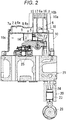
Fig. 2 is a vertical cross-sectional view of a main part of an engine including a breather chamber shown inFigs. 1A and 1B . -
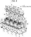
Fig. 3 is an exploded perspective view of the main part of the engine including the breather chamber shown inFigs. 1A and 1B . -
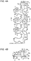
Figs. 4A and 4B are views for describing a modification of the breather chamber, whereinFig. 4A is a transverse cross-sectional plan view, andFig. 4B is a cross-sectional view taken along a line B-B inFig. 4A . -
Fig. 1A to Fig. 3 are views for describing a basic example of a breather chamber of the engine according to the embodiment of the present invention,Figs. 4A and 4B are views for describing a modification of the breather chamber. In this embodiment, the description is made with respect to a vertical-type in-line multiple cylinder diesel engine. - As shown in
Fig. 2 , the engine includes: a cylinder block (20); a cylinder head (21) which is assembled to an upper portion of the cylinder block (20); and a cylinder head cover (10) which is assembled to an upper portion of the cylinder head (21). - The engine includes a valve operating device (22), and a breather chamber (1).
- The valve operating device (22) performs a valve opening operation of an exhaust valve (25) and an intake valve (not shown in the drawing) by way of a valve operating cam (26), a tappet (23), a pushing rod (24), and a rocker arm (12) in this order.
- The breather chamber (1) communicates with a rocker arm chamber (10c) in the cylinder head cover (10).
- As shown in all drawings, the engine includes the breather chamber (1).
- As shown in
Figs. 1A and 1B andFigs. 4A and 4B , the breather chamber (1) includes: a plurality of breather inlet chambers (4) each having a breather inlet (3) which opens in a bottom wall (2); an oil separation chamber (6) where blow-by gases (5) flown out from the plurality of breather inlet chambers (4) merge together and oil separation is performed; and a breather outlet (19). - As shown in
Fig. 1B ,Fig. 2 ,Fig. 3 andFig. 4B , ceiling walls (4a) of the respective breather inlet chambers (4) are set lower than a ceiling wall (6a) of the oil separation chamber (6). - Accordingly, this engine can acquire the above-mentioned advantageous effects of the present invention.
- As shown in all drawings, the respective breather inlet chambers (4) each have: a remote-side chamber portion (7) which is disposed remote from the oil separation chamber (6); and a near-side chamber portion (8) which is disposed near the oil separation chamber (6). A ceiling wall (8a) of the near-side chamber portion (8) is disposed lower than a ceiling wall (7a) of the remote-side chamber portion (7) with a stepped portion (9) formed between the ceiling wall (8a) and the ceiling wall (7a).
- In the engine, an oil which is condensed on the ceiling wall (7a) of the remote-side chamber portion (7) shown in
Fig. 1B ,Fig. 3 andFig. 4B is blocked by the stepped portion (9) so that the flow of oil is stopped and hence, the breather inlet chamber (4) can acquire a high oil separation performance. - In the basic example shown in
Fig. 1A to Fig. 3 , the breather inlet (3) is opened at the near-side chamber portion (8). However, in the modification shown inFigs. 4A and 4B , the breather inlet (3) is opened at the remote-side chamber portion (7). - As shown in
Fig. 1B ,Fig. 2 ,Fig. 3 andFig. 4B , the engine is characterized by the following technical features. The breather chamber (1) is formed in a ceiling portion (10a) of the cylinder head cover (10). - As shown in all drawings, in a state where an engine width direction is set as a lateral direction, the breather inlet chambers (4) extend sideward from the oil separation chamber (6).
- As shown in
Fig. 3 , a connector (11) of a wire harness of a fuel injector is disposed between a pair of breather inlet chambers (4) which are disposed adjacently to each other in a crankshaft extending direction. - In this engine, a foreign substance which approaches the connector (11) shown in
Fig. 3 is received by the oil separation chamber (6) having a large height and walls of the pair of breather inlet chambers (4) which sandwiches the connector (11) therebetween. Accordingly, it is possible to prevent the foreign substance from impinging on the connector (11). - As shown in
Fig. 3 , the breather chamber (1) is formed between a ceiling wall (10b) of the cylinder head cover (10) which houses the rocker arm (12) and the bottom wall (2) which opposedly faces the ceiling wall (10b). - The bottom wall (2) includes: a plurality of oil receiving wall portions (2a) shown in
Fig. 1A andFig. 4A which receive an injection oil (13) injected upward from the rocker arm (12) shown inFig. 2 ; and the breather inlets (3) which are opened at positions avoiding the oil receiving wall portions (2a). - In this engine, the injection oil (13) which is injected upward from the rocker arm (12) shown in
Fig. 2 minimally enters the breather chamber (1) through the breather inlets (3) so that an oil is minimally blown off through the breather chamber (1). - As shown in
Fig. 1A andFig. 4A , in a state where the engine width direction is set as the lateral direction, the breather inlet (3) is opened at a position displaced from the oil receiving wall portion (2a) in an obliquely sideward direction. - In this engine, even when an impingement position (13a) of the injection oil (13) at the oil receiving wall portion (2a) shown in
Fig. 1A ,Fig. 3 andFig. 4A is changed due to rocking of the rocker arm (12) shown inFig. 2 or blowing off of the blow-by gas (5), the injection oil (13) minimally enters the breather inlets (3). - As shown in
Fig. 1A andFig. 4A , the bottom wall (2) of the breather chamber (1) includes cylindrical oil receiving frames (14) which extend downward from peripheral portions of the breather inlets (3). - In this engine, a condensed oil which is blown off by the blow-by gas (5) on a lower surface of the bottom wall (2) of the breather chamber (1) is received by the oil receiving frames (14) and hence, the condensed oil minimally enters the breather inlets (3).
- As shown in
Fig. 1A andFig. 4A , the oil separation chamber (6) includes: a blow-by gas merging passage (15) where blow-by gasses (5) flown out from the plurality of breather inlet chambers (4) merge together; a blow-by gas detour passage (16) which guides the blow-by gas (5) in the blow-by gas merging passage (15) to the breather outlet (19) by detouring the blow-by gas (5); and a passage partition wall (17) by which the blow-by gas merging passage (15) and the blow-by gas detour passage (16) are separated from each other. - In this engine, oil mist contained in the blow-by gas (5) is condensed in a long passage formed in the oil separation chamber (6) and hence, the oil separation chamber (6) can acquire a high oil separation performance.
- Further, in this engine, as shown in
Fig. 1B ,Fig. 2 andFig. 4B , the oil separation chamber (6) having a large height can have a relatively large passage cross-sectional area even when the oil separation chamber (6) is partitioned by the passage partition wall (17). Accordingly, a passage resistance of the breather chamber (1) can be reduced. - As shown in
Fig. 1A ,Fig. 3 andFig. 4A , the passage partition wall (17) includes bent wall portions (17a). - In this engine, the blow-by gas (5) which passes through the long passage impinges on surfaces of the bent wall portions (17a) so that oil mist is condensed efficiently and hence, the oil separation chamber (6) can acquire a high oil separation performance.
- As shown in
Fig. 1A ,Fig. 3 andFig. 4A , the bent wall portions (17a) protrude toward the breather inlet (3) side respectively in the blow-by gas merging passage (15). - In this engine, as shown in
Fig. 1A andFig. 4A , the blow-by gas (5) which flows in the breather chamber (1) from the breather inlet (3) impinges on the bent wall portions (17a) close to the breather inlets (3) at a high speed so that condensation of oil mist contained in the blow-by gas (5) is accelerated whereby the blow-by gas merging passage (15) can acquire a high oil separation performance. - As shown in
Fig. 1A andFig. 4A , as viewed in a direction parallel to a center axis (3a) of the breather inlet (3), the bent wall portion (17a) is formed in a V shape where a width is gradually narrowed toward the breather inlet (3) side. - In this engine, the respective blow-by gasses (5) which flow into the breather chamber (1) through the plurality of breather inlets (3) advance in the oil separation chamber (6) in a meandering manner by being guided by the V-shaped bent walls, and impinge on each other in a crossing manner, and small oil droplets in the oil mist contained in the blow-by gas are merged together thus forming large oil droplets, and the large oil droplets fall down and are condensed. Accordingly, the oil separation chamber (6) can acquire a high oil separation performance.
- As shown in
Fig. 1A andFig. 4A , the breather chamber (1) includes a pair of merging passage outlets (15a), (15a) which are provided on both end sides of the passage partition wall (17), the blow-by gas merging passage (15) communicates with both end sides of the blow-by gas detour passage (16) through the respective merging passage outlets (15a) on both end side of the blow-by gas merging passage (15), and the breather outlet (19) is disposed on a center portion of the blow-by gas detour passage (16) in a longitudinal direction of the blow-by gas detour passage (16). - In this engine, the pair of blow-by gasses (5) which is distributed by the pair of merging chamber outlets (15a), (15a) flow out through the breather outlet (19) from the blow-by gas detour passage (16) by way of the equal detour distance respectively. Accordingly, the blow-by gasses (5) can make use of the oil separation performance of the blow-by gas detour passage (16) without either excess or insufficiency and hence, the blow-by gas detour passage (16) exhibits a high oil separation performance.
- As shown in
Fig. 1B ,Fig. 2 andFig. 4B , the blow-by gas detour passage (16) includes baffle plates (18) which stand upright from the bottom wall (2). - In this engine, the blow-by gas (5) which passes through the blow-by gas detour passage (16) impinges on the baffle plates (18) and hence, the oil mist contained in the blow-by gas (5) is condensed on surfaces of the baffle plates (18). Accordingly, the blow-by gas detour passage (16) can acquire a high oil separation performance.
- Further, according to the present invention, even when the condensed oil accumulated on the bottom wall (2) of the blow-by gas detour passage (16) is blown off by the blow-by gas (5), the condensed oil is received by the baffle plates (18) and hence, the oil is minimally formed into mist again. Accordingly, it is possible to suppress the occurrence of a phenomenon that the condensed oil is formed into mist again in the blow-by gas detour passage (16).
- Further, according to the present invention, even when the baffle plates (18) stand upright from the bottom wall (2) of the blow-by gas detour passage (16), in the oil separation chamber (6) which has the relatively high ceiling wall (6a), the blow-by gas detour passage (16) can acquire a relatively large passage cross-sectional area and hence, a passage resistance of the breather chamber (1) can be reduced.
Claims (12)
- An engine comprising a breather chamber (1), wherein
the breather chamber (1) includes: a plurality of breather inlet chambers (4) each having a breather inlet (3) which opens on a bottom wall (2); an oil separation chamber (6) where blow-by gases (5) flown out from the plurality of breather inlet chambers (4) merge together and oil separation is performed; and a breather outlet (19), wherein
a ceiling wall (4a) of each breather inlet chamber (4) is lower than a ceiling wall (6a) of an oil separation chamber (6). - The engine according to claim 1, wherein the respective breather inlet chambers (4) each have: a remote-side chamber portion (7) which is disposed remote from the oil separation chamber (6); and a near-side chamber portion (8) which is disposed near the oil separation chamber (6), and a ceiling wall (8a) of the near-side chamber portion (8) is disposed lower than a ceiling wall (7a) of the remote-side chamber portion (7) with a stepped portion (9) formed between the ceiling wall (8a) and the ceiling wall (7a).
- The engine according to claim 2, wherein
the breather chamber (1) is formed in a ceiling portion (10a) of the cylinder head cover (10),
the breather inlet chambers (4) extend sideward from the oil separation chamber (6) in a state where an engine width direction is set as a lateral direction, and
a connector (11) of a wire harness of a fuel injector is disposed between a pair of breather inlet chambers (4) which is disposed adjacently to each other in a crankshaft extending direction. - The engine according to any one of claims 1 to 3, wherein
the breather chamber (1) is formed between a ceiling wall (10b) of the cylinder head cover (10) which houses a rocker arm (12) and the bottom wall (2) which opposedly faces the ceiling wall (10b), and
the bottom wall (2) includes: a plurality of oil receiving wall portions (2a) which receive an injection oil (13) injected upward from the rocker arm (12); and breather inlets (3) which open at positions avoiding the oil receiving wall portions (2a). - The engine according to claim 4, wherein the breather inlet (3) is opened at a position displaced from the oil receiving wall portion (2a) in an obliquely sideward direction in a state where an engine width direction is set as a lateral direction.
- The engine according to claim 4 or 5, wherein the bottom wall (2) of the breather chamber (1) includes a cylindrical oil receiving frame (14) which extends downward from a peripheral portion of the breather inlet (3).
- The engine according to any one of claims 1 to 6, wherein the oil separation chamber (6) includes: a blow-by gas merging passage (15) where blow-by gases (5) flown out from the plurality of breather inlet chambers (4) merge together; a blow-by gas detour passage (16) which guides the blow-by gas (5) in the blow-by gas merging passage (15) to a breather outlet (19) by detouring the blow-by gas (5); and a passage partition wall (17) by which the blow-by gas merging passage (15) and the blow-by gas detour passage (16) are separated from each other.
- The engine according to claim 7, wherein the passage partition wall (17) includes a bent wall portion (17a).
- The engine according to claim 8, wherein the bent wall portion (17a) protrudes toward the breather inlet (3) side in the blow-by gas merging passage (15).
- The engine according to claim 9, wherein, as viewed in a direction parallel to a center axis (3a) of the breather inlet (3), the bent wall portion (17a) is formed in a V shape where a width is gradually narrowed toward a breather inlet (3) side.
- The engine according to any one of claims 7 to 10, wherein the breather chamber (1) includes a pair of merging passage outlets (15a, 15a) disposed on both end sides of the passage partition wall (17), the blow-by gas merging passage (15) communicates with both end sides of the blow-by gas detour passage (16) through the respective merging passage outlets (15a) on the both end sides, and the breather outlet (19) is disposed at a center portion of the blow-by gas detour passage (16) in a longitudinal direction of the blow-by gas detour passage (16).
- The engine according to any one of claims 7 to 11, wherein the blow-by gas detour passage (16) includes a baffle plate (18) which stands upright from the bottom wall (2).
Applications Claiming Priority (2)
| Application Number | Priority Date | Filing Date | Title |
|---|---|---|---|
| JP2018248837A JP2020109271A (en) | 2018-12-31 | 2018-12-31 | engine |
| JP2018248836A JP2020109270A (en) | 2018-12-31 | 2018-12-31 | engine |
Publications (1)
| Publication Number | Publication Date |
|---|---|
| EP3674522A1 true EP3674522A1 (en) | 2020-07-01 |
Family
ID=68280760
Family Applications (1)
| Application Number | Title | Priority Date | Filing Date |
|---|---|---|---|
| EP19202560.9A Withdrawn EP3674522A1 (en) | 2018-12-31 | 2019-10-10 | Engine |
Country Status (3)
| Country | Link |
|---|---|
| US (1) | US20200208552A1 (en) |
| EP (1) | EP3674522A1 (en) |
| CN (1) | CN111379609A (en) |
Cited By (1)
| Publication number | Priority date | Publication date | Assignee | Title |
|---|---|---|---|---|
| US20220090526A1 (en) * | 2020-09-21 | 2022-03-24 | Caterpillar Inc. | Internal combustion engine with purge system |
Families Citing this family (1)
| Publication number | Priority date | Publication date | Assignee | Title |
|---|---|---|---|---|
| CN114251156A (en) * | 2020-09-21 | 2022-03-29 | 深圳臻宇新能源动力科技有限公司 | Oil-gas separator |
Citations (8)
| Publication number | Priority date | Publication date | Assignee | Title |
|---|---|---|---|---|
| US4597372A (en) * | 1984-09-26 | 1986-07-01 | Toyota Jidosha Kabushiki Kaisha | Oil separator for blowby gas |
| US4602595A (en) * | 1984-03-01 | 1986-07-29 | Aisin Seiki Kabushiki Kaisha | Oil separator for internal combustion engine |
| JPS62122108U (en) | 1986-01-24 | 1987-08-03 | ||
| US4723529A (en) * | 1985-07-19 | 1988-02-09 | Toyota Jidosha Kabushiki Kaisha | Oil separator for a blowby gas ventilation system of an internal combustion engine |
| US5944001A (en) * | 1995-12-22 | 1999-08-31 | Rover Group Limited | Liquid from gas separator and an internal combustion engine including same |
| JP2005139934A (en) * | 2003-11-05 | 2005-06-02 | Mazda Motor Corp | Engine oil separator |
| US20100313861A1 (en) * | 2008-03-12 | 2010-12-16 | Renault S.A.S | improved-efficiency device for recovering the oil contained in combustion gas |
| US20160333753A1 (en) * | 2015-05-14 | 2016-11-17 | Toyota Boshoku Kabushiki Kaisha | Blow-by gas passage structure |
-
2019
- 2019-10-10 EP EP19202560.9A patent/EP3674522A1/en not_active Withdrawn
- 2019-10-21 US US16/658,935 patent/US20200208552A1/en not_active Abandoned
- 2019-11-06 CN CN201911077472.6A patent/CN111379609A/en active Pending
Patent Citations (8)
| Publication number | Priority date | Publication date | Assignee | Title |
|---|---|---|---|---|
| US4602595A (en) * | 1984-03-01 | 1986-07-29 | Aisin Seiki Kabushiki Kaisha | Oil separator for internal combustion engine |
| US4597372A (en) * | 1984-09-26 | 1986-07-01 | Toyota Jidosha Kabushiki Kaisha | Oil separator for blowby gas |
| US4723529A (en) * | 1985-07-19 | 1988-02-09 | Toyota Jidosha Kabushiki Kaisha | Oil separator for a blowby gas ventilation system of an internal combustion engine |
| JPS62122108U (en) | 1986-01-24 | 1987-08-03 | ||
| US5944001A (en) * | 1995-12-22 | 1999-08-31 | Rover Group Limited | Liquid from gas separator and an internal combustion engine including same |
| JP2005139934A (en) * | 2003-11-05 | 2005-06-02 | Mazda Motor Corp | Engine oil separator |
| US20100313861A1 (en) * | 2008-03-12 | 2010-12-16 | Renault S.A.S | improved-efficiency device for recovering the oil contained in combustion gas |
| US20160333753A1 (en) * | 2015-05-14 | 2016-11-17 | Toyota Boshoku Kabushiki Kaisha | Blow-by gas passage structure |
Cited By (2)
| Publication number | Priority date | Publication date | Assignee | Title |
|---|---|---|---|---|
| US20220090526A1 (en) * | 2020-09-21 | 2022-03-24 | Caterpillar Inc. | Internal combustion engine with purge system |
| US11454147B2 (en) * | 2020-09-21 | 2022-09-27 | Caterpillar Inc. | Internal combustion engine with purge system |
Also Published As
| Publication number | Publication date |
|---|---|
| US20200208552A1 (en) | 2020-07-02 |
| CN111379609A (en) | 2020-07-07 |
Similar Documents
| Publication | Publication Date | Title |
|---|---|---|
| JP4344579B2 (en) | Cylinder head cover oil separator | |
| US8408190B2 (en) | Air-oil separator for extracting oil from engine blowby gas | |
| US8256404B2 (en) | Oil separator for blow-by gas | |
| JP2009121281A (en) | Oil separator for internal combustion engine | |
| EP3674522A1 (en) | Engine | |
| JP2013113109A (en) | Head cover structure for internal combustion engine | |
| WO2012157309A1 (en) | Oil separator for internal combustion engine | |
| CN101680320A (en) | Breather device for engine | |
| US10533471B2 (en) | Internal combustion engine | |
| US8161951B2 (en) | Internal combustion engine | |
| JP2010203299A (en) | Oil separator | |
| US20090159056A1 (en) | PCV System for V-Type Engine | |
| US8844506B2 (en) | Positive crankcase ventilation system | |
| JPH07243317A (en) | Oil mist separator | |
| JP2004162625A (en) | Oil separator of blow-by gas reflux system | |
| JP2008121478A (en) | Blowby flow channel structure of internal combustion engine | |
| JP2924467B2 (en) | Oil return structure of internal combustion engine | |
| JP4419818B2 (en) | Internal combustion engine | |
| CN111379610A (en) | Cylinder head cover | |
| JP7103936B2 (en) | Blow-by gas recirculation device | |
| JP6412425B2 (en) | Oil separator inlet structure of internal combustion engine | |
| JPS6318747Y2 (en) | ||
| JP4918843B2 (en) | Rocker cover oil separator structure | |
| JP2020109270A (en) | engine | |
| JP2020109271A (en) | engine |
Legal Events
| Date | Code | Title | Description |
|---|---|---|---|
| PUAI | Public reference made under article 153(3) epc to a published international application that has entered the european phase |
Free format text: ORIGINAL CODE: 0009012 |
|
| STAA | Information on the status of an ep patent application or granted ep patent |
Free format text: STATUS: THE APPLICATION HAS BEEN PUBLISHED |
|
| AK | Designated contracting states |
Kind code of ref document: A1 Designated state(s): AL AT BE BG CH CY CZ DE DK EE ES FI FR GB GR HR HU IE IS IT LI LT LU LV MC MK MT NL NO PL PT RO RS SE SI SK SM TR |
|
| STAA | Information on the status of an ep patent application or granted ep patent |
Free format text: STATUS: REQUEST FOR EXAMINATION WAS MADE |
|
| 17P | Request for examination filed |
Effective date: 20201211 |
|
| RBV | Designated contracting states (corrected) |
Designated state(s): AL AT BE BG CH CY CZ DE DK EE ES FI FR GB GR HR HU IE IS IT LI LT LU LV MC MK MT NL NO PL PT RO RS SE SI SK SM TR |
|
| STAA | Information on the status of an ep patent application or granted ep patent |
Free format text: STATUS: THE APPLICATION IS DEEMED TO BE WITHDRAWN |
|
| 18D | Application deemed to be withdrawn |
Effective date: 20220503 |