EP3674477A1 - Fabric treating appliance with pelletizer - Google Patents
Fabric treating appliance with pelletizer Download PDFInfo
- Publication number
- EP3674477A1 EP3674477A1 EP19214557.1A EP19214557A EP3674477A1 EP 3674477 A1 EP3674477 A1 EP 3674477A1 EP 19214557 A EP19214557 A EP 19214557A EP 3674477 A1 EP3674477 A1 EP 3674477A1
- Authority
- EP
- European Patent Office
- Prior art keywords
- lint
- pellet
- treating appliance
- laundry treating
- pelletizer
- Prior art date
- Legal status (The legal status is an assumption and is not a legal conclusion. Google has not performed a legal analysis and makes no representation as to the accuracy of the status listed.)
- Granted
Links
Images

Classifications
-
- D—TEXTILES; PAPER
- D06—TREATMENT OF TEXTILES OR THE LIKE; LAUNDERING; FLEXIBLE MATERIALS NOT OTHERWISE PROVIDED FOR
- D06F—LAUNDERING, DRYING, IRONING, PRESSING OR FOLDING TEXTILE ARTICLES
- D06F58/00—Domestic laundry dryers
- D06F58/20—General details of domestic laundry dryers
- D06F58/22—Lint collecting arrangements
-
- D—TEXTILES; PAPER
- D06—TREATMENT OF TEXTILES OR THE LIKE; LAUNDERING; FLEXIBLE MATERIALS NOT OTHERWISE PROVIDED FOR
- D06F—LAUNDERING, DRYING, IRONING, PRESSING OR FOLDING TEXTILE ARTICLES
- D06F25/00—Washing machines with receptacles, e.g. perforated, having a rotary movement, e.g. oscillatory movement, the receptacle serving both for washing and for centrifugally separating water from the laundry and having further drying means, e.g. using hot air
-
- D—TEXTILES; PAPER
- D06—TREATMENT OF TEXTILES OR THE LIKE; LAUNDERING; FLEXIBLE MATERIALS NOT OTHERWISE PROVIDED FOR
- D06F—LAUNDERING, DRYING, IRONING, PRESSING OR FOLDING TEXTILE ARTICLES
- D06F39/00—Details of washing machines not specific to a single type of machines covered by groups D06F9/00 - D06F27/00
- D06F39/10—Filtering arrangements
Definitions
- the present disclosure relates to a method and apparatus for operating a laundry treating appliance and more specifically to trapping and pelletizing lint.
- Lint is any type of fiber that separates from clothing and is a byproduct of washing, drying or treating clothing in a fabric treating appliance, such as a clothes washer, clothes dryer or combination clothes washer/dryer, as part of an automatic cycle of operation.
- a fabric treating appliance such as a clothes washer, clothes dryer or combination clothes washer/dryer
- the lint is entrained in the waste liquid, which, depending on the machine, is ultimately flushed down the household drain.
- a laundry treating appliance comprising: a treating chamber with a fluid circuit; a lint trap fluidly coupled to the fluid circuit; and a lint pelletizer having an inlet coupled to the lint trap; whereby lint from the fluid circuit is trapped by the line lint trap and formed into a pellet by the lint pelletizer.
- a method for pelletizing lint entrained in fluid for laundry treatment in a household appliance comprising: trapping the lint from the fluid for laundry treatment, compressing the trapped lint into a pellet, and fusing at least a portion of the lint in the pellet.
- FIG. 1 illustrates a laundry treating appliance in the form of a top-loading, vertical axis washing machine 10 incorporating a lint pelletizer 12.
- the vertical axis washing machine 10 comprises a chassis or cabinet 14 defining an interior 16 accessible through a top door 18.
- a tub 22 is located within the interior 16 and defines a fluid tank for holding water, wash liquid, and the like.
- a basket 24 is located within and rotatable relative to the tub 22.
- the basket 24 defines a treating chamber 26 for receiving laundry, such as clothes, for treatment.
- the basket 24 can have drain holes, such as perforations 28, through which liquid can pass to and from the tub 22.
- a clothes mover shown as an impeller 30 is located within the treating chamber 26 and is rotationally driven by a motor 32, which can also rotate the basket 24.
- the impeller 30 is one example of a suitable clothes mover.
- Other clothes movers like an agitator, auger, nutator, etc. are contemplated.
- a household water supply 36 is provided and supplies water, hot or cold, to the treating chamber 26 directly or indirectly.
- a dispenser 38 is fluidly coupled to the household water supply 36.
- the dispenser 38 can be filled with one or more charges of treating chemistry, which is then flushed into the treating chamber 26 from the household water supply 36.
- a fluid recirculation circuit 40 is provided to recirculate liquid into the treating chamber 26.
- the recirculation circuit 40 comprises a recirculation pump 42 that is supplied by a sump or sump line 44 that is fluidly coupled to the tub 22.
- An output line 46 receives liquid from the recirculation pump 42 and returns the liquid to the treating chamber 26.
- a spray head 48 or some other type of distribution device or nozzle can be located on the end of the output line 46.
- a fluid drain circuit 50 is provided to drain liquid from the treating chamber 26.
- the drain circuit 50 comprises a drain pump 52 that is supplied by the sump or sump line 44.
- a drain line 54 receives liquid from the drain pump 52 and sends the liquid to a household drain.
- the pelletizer 12 is fluidly coupled to both of the recirculation and drain circuits 40, 50. In the illustrated implementation, the pelletizer forms a junction between both the circuits, but this is not necessary.
- the pelletizer 12 is situated such that it is supplied liquid from the sump line 44 and the supplied liquid can then be directed to the recirculation circuit 40 or drain circuit 50 by the activation of the corresponding recirculation pump 42 or drain pump 52.
- a controller 60 is operably coupled to the pelletizer 12, motor 32, household water supply 36, recirculation pump 42, and drain pump 52 to control their respective operation during the implementing of a treating cycle of operation or sub-cycle of operation, such as a pelletizing cycle, where lint entrained in the liquid is formed into a pellet P. While shown in the lower left of the cabinet 14, the controller 60 can be located anywhere within or on the cabinet 14 and includes a user interface, which can be remote from the processor of the controller 60.
- the pelletizer 12 includes a lint trap 70, a hopper 72, and a ram 74, which are operationally interconnected to form a lint pellet P from lint entrained in the liquid.
- the lint trap 70 can be any suitable device for trapping lint and is illustrated as a filter in the form of a mesh or screen 80 through which passes the liquid from the sump line 44.
- a lint mover which is illustrated as a wiper 82, moves over the screen 80 in the direction of arrow 84 to direct any lint trapped on the screen 80 into the hopper 72.
- the hopper 72 defines a hopper chamber 90 for receiving the trapped lint.
- the hopper 72 can have a piston 92 that is reciprocated into and out of the hopper chamber 90 by an actuator, such as solenoid 94.
- the reciprocation of the piston 92 moves the lint in the hopper chamber 90 into the ram 74.
- the piston 92 is not necessary. In that sense, neither is the hopper 72. It is possible to configure the pelletizer 12 such that the trapped lint can be moved to the ram 74 without the hopper 72.
- the ram 74 defines a pellet chamber 100 having drain holes 102.
- a pellet piston 104 can be reciprocated within the pellet chamber 100 by an actuator, such as solenoid 108. If greater mechanical leverage is needed, a force multiplier, such as a gear train with motor, could be used.
- a heater in the form of a film heater 106 surrounds the pellet chamber and thereby heats the contents of the pellet chamber 100. While a film heater 106 is illustrated, any type of heater can be used. For example, a coiled resistive heater could be wrapped around the pellet chamber 100 while leaving spaces, if need be, for the drain holes 102. In place of or in addition to the drain holes 102, a small gap can be left between the piston and the pellet chamber through which the water, water vapor, or steam can escape.
- the wiper 82, solenoids 94, 108, and heater 106 are all operably coupled to the controller 60 and selectively controllable by the controller 60 to effect a suitable lint pelletizing operation.
- liquid will be recirculated through the recirculation circuit 40, with the liquid passing through the screen 80, which traps the lint L entrained within the liquid.
- the lint L trapped on the screen 80 can be moved by the wiper 82 into the hopper chamber 90.
- the piston 92 is then reciprocated into the hopper chamber 90 to move the lint L into the pellet chamber 100.
- the piston 92 can remain in a position closing off an upper end of the pellet chamber 100 to function as a back plate for the pellet piston 104.
- the pellet piston 104 can then be reciprocated into the pellet chamber 100 compressing the lint L against the piston 92 to form a pellet P of lint L. Liquid squeezed from the lint L during the forming of the pellet P can exit the pellet chamber 100 through the drain holes 102.
- the heater 106 can then be activated to heat the pellet chamber 100, which conducts heat to the pellet P, which is heated to a temperature sufficient to fuse together at least some of the outermost lint fibers forming the pellet P.
- the piston 92 is reciprocated out of the hopper chamber 90 and the pellet piston 104 is advanced further to expel the pellet P from the pellet chamber 100 into the hopper chamber 90, where the pellet P can be drained away with the liquid during a draining operation.
- a suitable degree of fusing is any amount of fusing where most of the lint L forming the pellet P stays together as a mass, even if the mass does not retain the original pellet shape.
- the fusing can include a complete or partial melting of all, some or a portion of some of at least the outermost fibers. The fusing can result in a mechanical or chemical connection between some of the fibers.
- the fused fibers become sufficiently soft, molten, or even fully melt along at least a portion of the fiber mechanically couple, once cooled, with an adjacent fiber, which may or may not have become soft, molten or fully melt.
- the heat can provide sufficient energy for the chemicals of adjacent fibers to chemical break their bonds and form new bonds with each other. In most cases, it is anticipated that the likely fibers will result in a mechanical connection.
- a suitable pellet size is a cylinder on the order of a 1 ⁇ 4" diameter and a 1 ⁇ 2" in length. While the pellet P can be any shape and size, as it is contemplated that the pellet P will be drained away. Thus, the pellet P need be small enough that it will not clog any household plumbing, yet large enough that it is easily captured by a municipal water treatment plant. It is also contemplated that the pellet P can be stored within the laundry treating appliance for removal by a user.
- the implementation of the pelletizing cycle can take place at any time. It can be initiated before or as part of the drain phase, where liquid is drained from the laundry treating appliance. It can be implemented multiple times during a given cycle of operation, after a certain number of cycles of operation, after an amount of time of operation, or a sensor can be provided to sense the amount of lint L accumulated on the screen 80.
- the pelletizer 12 can be implemented in other fabric treating appliances than a vertical axis clothes washer. It can, for example, be implemented in a horizontal axis clothes washer.
- a pelletizer 112 can be implemented as a clothes dryer 110.
- the clothes dryer 110 includes a cabinet 114 that defines an interior 116 housing a rotating drum 124 defining a treating chamber 126, which receives fluid, in the form of air, through an inlet vent 128, and exhausts air through an exhaust vent 130. The air is continuously recirculated via a recirculation circuit 132 through the treating chamber 126 by recirculating the air exiting the exhaust vent 130 back to the inlet vent 128.
- the pelletizer 112 is located within the recirculation circuit 132.
- the pelletizer 112 has an almost identical structure to the pelletizer 12, with identical parts increased by 100, in that it has a lint trap 170 in the form of a screen 180 with a wiper 182; a hopper 172 with a hopper chamber 190, piston 192, and solenoid 194; a ram 174 with a pellet chamber 200; and a heater 206.
- These identical structures will not be described in detail as the description of these structures for the pelletizer 12 applies. What will be described are the primary differences in the pelletizer 112 as compared to the pelletizer 12.
- the pelletizer 112 does not include a separate pellet piston 104. Instead, a back plate 210 having a corresponding solenoid 212 is provided and takes the place of the pellet piston 104. An output bin 214 is provided by the back plate 210.
- the operation of the pelletizer 112 is essentially the same as described for the pelletizer 12 in that the wiper 182 moves the lint L captured on the screen 180 into the hopper chamber 190, the piston 192 moves the lint L from the hopper chamber 190 into the pellet chamber 200. What differs is that the piston 192 is also used to compress the lint L in the pellet chamber 200 against the back plate 210. Once the lint L is compressed into a pellet, the heater 206 is actuated to fuse the lint L. After fusing, the solenoid 212 is actuated to withdraw the back plate 210 and open the pellet chamber 200, where further advancement of the piston 192 expels the pellet into the output bin 214 for storage until removed by a user.
Landscapes
- Engineering & Computer Science (AREA)
- Textile Engineering (AREA)
- Processing And Handling Of Plastics And Other Materials For Molding In General (AREA)
- Detail Structures Of Washing Machines And Dryers (AREA)
Abstract
Description
- The present disclosure relates to a method and apparatus for operating a laundry treating appliance and more specifically to trapping and pelletizing lint.
- Lint is any type of fiber that separates from clothing and is a byproduct of washing, drying or treating clothing in a fabric treating appliance, such as a clothes washer, clothes dryer or combination clothes washer/dryer, as part of an automatic cycle of operation. In many fabric treating appliances, the lint is entrained in the waste liquid, which, depending on the machine, is ultimately flushed down the household drain.
- The nature of lint when it is entrained in waste water, especially its fine size, makes it difficult to trap or filter conveniently in the fabric treating appliance or in a municipal waste treatment plant receiving the waste water for processing. While entrained lint can be filtered from a waste liquid stream, it can quickly clog filters and because of its string-like shape, it can be difficult to remove from the filter.
- A laundry treating appliance comprising: a treating chamber with a fluid circuit; a lint trap fluidly coupled to the fluid circuit; and a lint pelletizer having an inlet coupled to the lint trap; whereby lint from the fluid circuit is trapped by the line lint trap and formed into a pellet by the lint pelletizer.
- A method for pelletizing lint entrained in fluid for laundry treatment in a household appliance, the method comprising: trapping the lint from the fluid for laundry treatment, compressing the trapped lint into a pellet, and fusing at least a portion of the lint in the pellet.
-
-
Figure 1 is a schematic front view of a laundry treating appliance in the form of a clothes washer with a lint pelletizer. -
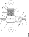
Figure 2 is an enlarged view of the lint pelletizer ofFigure 1 . -
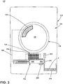
Figure 3 is a schematic front view of a laundry treating appliance in the form of a clothes dryer with a lint pelletizer. -
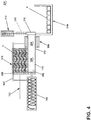
Figure 4 is an enlarged view of the lint pelletizer ofFigure 3 . -
Figure 1 illustrates a laundry treating appliance in the form of a top-loading, verticalaxis washing machine 10 incorporating alint pelletizer 12. The verticalaxis washing machine 10 comprises a chassis orcabinet 14 defining aninterior 16 accessible through atop door 18. Atub 22 is located within theinterior 16 and defines a fluid tank for holding water, wash liquid, and the like. Abasket 24 is located within and rotatable relative to thetub 22. Thebasket 24 defines a treatingchamber 26 for receiving laundry, such as clothes, for treatment. Thebasket 24 can have drain holes, such asperforations 28, through which liquid can pass to and from thetub 22. - A clothes mover shown as an
impeller 30 is located within the treatingchamber 26 and is rotationally driven by amotor 32, which can also rotate thebasket 24. Theimpeller 30 is one example of a suitable clothes mover. Other clothes movers like an agitator, auger, nutator, etc. are contemplated. - A
household water supply 36 is provided and supplies water, hot or cold, to the treatingchamber 26 directly or indirectly. Adispenser 38 is fluidly coupled to thehousehold water supply 36. Thedispenser 38 can be filled with one or more charges of treating chemistry, which is then flushed into the treatingchamber 26 from thehousehold water supply 36. - A
fluid recirculation circuit 40 is provided to recirculate liquid into the treatingchamber 26. Therecirculation circuit 40 comprises arecirculation pump 42 that is supplied by a sump orsump line 44 that is fluidly coupled to thetub 22. Anoutput line 46 receives liquid from therecirculation pump 42 and returns the liquid to the treatingchamber 26. A spray head 48 or some other type of distribution device or nozzle can be located on the end of theoutput line 46. - A
fluid drain circuit 50 is provided to drain liquid from the treatingchamber 26. Thedrain circuit 50 comprises adrain pump 52 that is supplied by the sump orsump line 44. Adrain line 54 receives liquid from thedrain pump 52 and sends the liquid to a household drain. - The
pelletizer 12 is fluidly coupled to both of the recirculation anddrain circuits pelletizer 12 is situated such that it is supplied liquid from thesump line 44 and the supplied liquid can then be directed to therecirculation circuit 40 ordrain circuit 50 by the activation of thecorresponding recirculation pump 42 ordrain pump 52. - A
controller 60 is operably coupled to thepelletizer 12,motor 32,household water supply 36,recirculation pump 42, anddrain pump 52 to control their respective operation during the implementing of a treating cycle of operation or sub-cycle of operation, such as a pelletizing cycle, where lint entrained in the liquid is formed into a pellet P. While shown in the lower left of thecabinet 14, thecontroller 60 can be located anywhere within or on thecabinet 14 and includes a user interface, which can be remote from the processor of thecontroller 60. - Referring to
Figure 2 , thepelletizer 12 includes alint trap 70, ahopper 72, and aram 74, which are operationally interconnected to form a lint pellet P from lint entrained in the liquid. Thelint trap 70 can be any suitable device for trapping lint and is illustrated as a filter in the form of a mesh orscreen 80 through which passes the liquid from thesump line 44. A lint mover, which is illustrated as awiper 82, moves over thescreen 80 in the direction ofarrow 84 to direct any lint trapped on thescreen 80 into thehopper 72. - The
hopper 72 defines a hopper chamber 90 for receiving the trapped lint. As illustrated, thehopper 72 can have apiston 92 that is reciprocated into and out of the hopper chamber 90 by an actuator, such assolenoid 94. The reciprocation of thepiston 92 moves the lint in the hopper chamber 90 into theram 74. Thepiston 92 is not necessary. In that sense, neither is thehopper 72. It is possible to configure thepelletizer 12 such that the trapped lint can be moved to theram 74 without thehopper 72. - The
ram 74 defines a pellet chamber 100 having drain holes 102. Apellet piston 104 can be reciprocated within the pellet chamber 100 by an actuator, such assolenoid 108. If greater mechanical leverage is needed, a force multiplier, such as a gear train with motor, could be used. A heater, in the form of afilm heater 106 surrounds the pellet chamber and thereby heats the contents of the pellet chamber 100. While afilm heater 106 is illustrated, any type of heater can be used. For example, a coiled resistive heater could be wrapped around the pellet chamber 100 while leaving spaces, if need be, for the drain holes 102. In place of or in addition to the drain holes 102, a small gap can be left between the piston and the pellet chamber through which the water, water vapor, or steam can escape. - The
wiper 82,solenoids heater 106 are all operably coupled to thecontroller 60 and selectively controllable by thecontroller 60 to effect a suitable lint pelletizing operation. For example, during a typical treating cycle of operation, liquid will be recirculated through therecirculation circuit 40, with the liquid passing through thescreen 80, which traps the lint L entrained within the liquid. The lint L trapped on thescreen 80 can be moved by thewiper 82 into the hopper chamber 90. Thepiston 92 is then reciprocated into the hopper chamber 90 to move the lint L into the pellet chamber 100. Thepiston 92 can remain in a position closing off an upper end of the pellet chamber 100 to function as a back plate for thepellet piston 104. Thepellet piston 104 can then be reciprocated into the pellet chamber 100 compressing the lint L against thepiston 92 to form a pellet P of lint L. Liquid squeezed from the lint L during the forming of the pellet P can exit the pellet chamber 100 through the drain holes 102. Theheater 106 can then be activated to heat the pellet chamber 100, which conducts heat to the pellet P, which is heated to a temperature sufficient to fuse together at least some of the outermost lint fibers forming the pellet P. After the fusing, thepiston 92 is reciprocated out of the hopper chamber 90 and thepellet piston 104 is advanced further to expel the pellet P from the pellet chamber 100 into the hopper chamber 90, where the pellet P can be drained away with the liquid during a draining operation. - It is contemplated that since the lint L is likely to be wet at the time of pelletizing only a portion of the outermost fibers will be fused together. It is not necessary for all of the fibers of the pellet P to be fused. A suitable degree of fusing is any amount of fusing where most of the lint L forming the pellet P stays together as a mass, even if the mass does not retain the original pellet shape. The fusing can include a complete or partial melting of all, some or a portion of some of at least the outermost fibers. The fusing can result in a mechanical or chemical connection between some of the fibers. In a mechanical connection, the fused fibers become sufficiently soft, molten, or even fully melt along at least a portion of the fiber mechanically couple, once cooled, with an adjacent fiber, which may or may not have become soft, molten or fully melt. In a chemical connection, the heat can provide sufficient energy for the chemicals of adjacent fibers to chemical break their bonds and form new bonds with each other. In most cases, it is anticipated that the likely fibers will result in a mechanical connection.
- It is further contemplated that a suitable pellet size is a cylinder on the order of a ¼" diameter and a ½" in length. While the pellet P can be any shape and size, as it is contemplated that the pellet P will be drained away. Thus, the pellet P need be small enough that it will not clog any household plumbing, yet large enough that it is easily captured by a municipal water treatment plant. It is also contemplated that the pellet P can be stored within the laundry treating appliance for removal by a user.
- The implementation of the pelletizing cycle can take place at any time. It can be initiated before or as part of the drain phase, where liquid is drained from the laundry treating appliance. It can be implemented multiple times during a given cycle of operation, after a certain number of cycles of operation, after an amount of time of operation, or a sensor can be provided to sense the amount of lint L accumulated on the
screen 80. - The
pelletizer 12 can be implemented in other fabric treating appliances than a vertical axis clothes washer. It can, for example, be implemented in a horizontal axis clothes washer. As seen inFigures 3 and4 , apelletizer 112 can be implemented as aclothes dryer 110. As the basic structure of aclothes dryer 110 is known, only the structure and features needed to set the environment for thepelletizer 112 are described. Theclothes dryer 110 includes acabinet 114 that defines an interior 116 housing arotating drum 124 defining a treatingchamber 126, which receives fluid, in the form of air, through aninlet vent 128, and exhausts air through anexhaust vent 130. The air is continuously recirculated via arecirculation circuit 132 through the treatingchamber 126 by recirculating the air exiting theexhaust vent 130 back to theinlet vent 128. - The
pelletizer 112 is located within therecirculation circuit 132. Thepelletizer 112 has an almost identical structure to thepelletizer 12, with identical parts increased by 100, in that it has alint trap 170 in the form of ascreen 180 with awiper 182; ahopper 172 with ahopper chamber 190,piston 192, andsolenoid 194; aram 174 with apellet chamber 200; and aheater 206. These identical structures will not be described in detail as the description of these structures for thepelletizer 12 applies. What will be described are the primary differences in thepelletizer 112 as compared to thepelletizer 12. - As can readily be seen, the
pelletizer 112 does not include aseparate pellet piston 104. Instead, aback plate 210 having a correspondingsolenoid 212 is provided and takes the place of thepellet piston 104. Anoutput bin 214 is provided by theback plate 210. - The operation of the
pelletizer 112 is essentially the same as described for thepelletizer 12 in that thewiper 182 moves the lint L captured on thescreen 180 into thehopper chamber 190, thepiston 192 moves the lint L from thehopper chamber 190 into thepellet chamber 200. What differs is that thepiston 192 is also used to compress the lint L in thepellet chamber 200 against theback plate 210. Once the lint L is compressed into a pellet, theheater 206 is actuated to fuse the lint L. After fusing, thesolenoid 212 is actuated to withdraw theback plate 210 and open thepellet chamber 200, where further advancement of thepiston 192 expels the pellet into theoutput bin 214 for storage until removed by a user. - It is intended that the following concepts can define at least a portion of the scope of the disclosure and that the apparatus and/or method(s) within the scope of these concepts and their equivalents be covered thereby. This disclosure should be understood to include all novel and non-obvious combinations of elements described herein, and the concepts may be presented in this or a later application to any novel and non-obvious combination of these elements. Any aspect of any embodiment can be combined with any aspect of any other embodiments. Moreover, the foregoing embodiments are illustrative, and no single feature or element is essential to all possible combinations that may be included in this or a later application. Further aspects of the invention are provided by the subject matter of the following clauses:
- 1. A laundry treating appliance comprising: a treating chamber with a fluid circuit, a lint trap fluidly coupled to the fluid circuit, and a lint pelletizer having an inlet coupled to the lint trap, whereby lint from the fluid circuit is trapped by the line lint trap and formed into a pellet by the lint pelletizer.
- 2. The laundry treating appliance of any preceding clause wherein the lint trap comprises at least one of a filter or screen located in the fluid circuit.
- 3. The laundry treating appliance of any preceding clause wherein the lint trap further comprises a wiper movable over the lint trap to move lint on the lint trap to the lint pelletizer.
- 4. The laundry treating appliance of any preceding clause wherein the lint trap further comprises a screen and the wiper moves across the screen.
- 5. The laundry treating appliance of any preceding clause wherein the lint trap further comprises a ram to compress the lint into a pellet.
- 6. The laundry treating appliance of any preceding clause wherein the ram further comprises a heater that applies heat to the pellet.
- 7. The laundry treating appliance of any preceding clause wherein the ram further comprises a pellet chamber.
- 8. The laundry treating appliance of any preceding clause wherein the heater further comprises at least one of a film heater or a coiled resistive heater located about at least a portion of the pellet chamber.
- 9. The laundry treating appliance of any preceding clause wherein the ram further comprises a ram piston reciprocating in the pellet chamber to compress the lint into the pellet.
- 10. The laundry treating appliance of any preceding clause wherein the heater is located around at least a portion of the pellet chamber.
- 11. The laundry treating appliance of any preceding clause wherein the pellet chamber has drain holes.
- 12. The laundry treating appliance of any preceding clause further comprising a hopper connecting the lint trap to the pelletizer.
- 13. The laundry treating appliance of any preceding clause wherein the lint trap comprises a lint mover that moves the lint from the lint trap into the hopper.
- 14. The laundry treating appliance of any preceding clause wherein the hopper comprises a hopper piston reciprocating within the hopper to move the lint from the hopper into the lint pelletizer.
- 15. The laundry treating appliance of any preceding clause wherein the laundry treating appliance is at least one of a clothes washer or a clothes dryer.
- 16. A method for pelletizing lint entrained in waste liquid in a household appliance, the method comprising trapping the lint from the waste liquid, compressing the trapped lint into a pellet, and fusing at least a portion of the lint in the pellet.
- 17. The method of any preceding clause wherein the fusing comprises fusing at least some of the lint on an exterior of the pellet.
- 18. The method of any preceding clause wherein the fusing comprises applying sufficient heat to at least soften at least some of the lint on the exterior of the pellet.
- 19. The method of any preceding clause wherein the applied heat is sufficient to render molten at least some of the lint on the exterior of the pellet.
- 20. The method of any preceding clause wherein the applied heat is sufficient to melt at least some of the lint on the exterior of the pellet.
- 21. The method of any preceding clause wherein the pellet is less than ¼" wide and ½" long.
Claims (15)
- A laundry treating appliance (10, 110) comprising:a treating chamber (26, 126) with a fluid circuit (40, 50);a lint trap (70, 170) fluidly coupled to the fluid circuit (40, 50); anda lint pelletizer (12, 112) having an inlet coupled to the lint trap (70, 170);whereby the lint trap (70, 170) is configured to trap lint (L) from the fluid circuit (40, 50) and the lint pelletizer (12, 112) is configured to form a pellet (P) from the lint (L).
- The laundry treating appliance (10, 110) of claim 1 wherein the lint trap (70, 170) comprises at least one of a filter or screen (80, 180) located in the fluid circuit (40, 50).
- The laundry treating appliance (10, 110) of any preceding claim wherein the lint trap (70, 170) further comprises a wiper (82, 182) movable over the lint trap (70, 170) to move lint (L) on the lint trap (70, 170) to the lint pelletizer (12, 112).
- The laundry treating appliance (10, 110) of claim 3 wherein the lint trap (70, 170) further comprises a screen (80, 180) and the wiper (82, 182) moves across the screen (80, 180).
- The laundry treating appliance (10, 110) of any preceding claim wherein the lint pelletizer (12, 112) comprises a ram (74, 174) to compress the lint (L) into a pellet (P).
- The laundry treating appliance (10, 110) of claim 5 wherein the ram (74, 174) further comprises a pellet chamber (100, 200) and a heater (106, 206) that applies heat to the pellet (P).
- The laundry treating appliance (10, 110) of claim 6 wherein the heater (106, 206) comprises at least one of a film heater or a coiled resistive heater located about at least a portion of the pellet chamber (100, 200).
- The laundry treating appliance (10, 110) of any of claims 6-7 wherein the ram (74, 174) further comprises a ram piston (104) reciprocating in the pellet chamber (100, 200) to compress the lint into the pellet (P).
- The laundry treating appliance (10, 110) of any of claims 6-8 wherein the heater (106, 206) is located around at least a portion of the pellet chamber (100, 200).
- The laundry treating appliance (10, 110) of any of claims 6-9 wherein the pellet chamber (100, 200) has drain holes (102).
- The laundry treating appliance (10, 110) of any of the preceding claims further comprises a hopper (72, 172) connecting the lint trap (70, 170) to the pelletizer (12, 112).
- The laundry treating appliance (10, 110) of claim 11 wherein the lint trap (70, 170) comprises a lint mover (82, 182) that moves the lint (L) from the lint trap (70, 170) into the hopper (72, 172).
- The laundry treating appliance (10, 110) of any of claims 11-12 wherein the hopper (72, 172) comprises a hopper piston (92, 192) reciprocating within the hopper (72, 172) to move the lint (L) from the hopper (72, 172) into the lint pelletizer (12, 112).
- A method for pelletizing lint (L) entrained in fluid for laundry treatment in a household appliance (10, 110), the method comprising:trapping the lint (L) from the fluid for laundry treatment,compressing the trapped lint into a pellet (P), andfusing at least a portion of the lint in the pellet (P).
- The method of claim 14 wherein the fusing comprises applying sufficient heat to at least soften at least some of the lint on the exterior of the pellet (P).
Applications Claiming Priority (2)
| Application Number | Priority Date | Filing Date | Title |
|---|---|---|---|
| US201862785765P | 2018-12-28 | 2018-12-28 | |
| US16/663,401 US11230806B2 (en) | 2018-12-28 | 2019-10-25 | Fabric treating appliance with pelletizer |
Publications (2)
| Publication Number | Publication Date |
|---|---|
| EP3674477A1 true EP3674477A1 (en) | 2020-07-01 |
| EP3674477B1 EP3674477B1 (en) | 2021-06-23 |
Family
ID=68840975
Family Applications (1)
| Application Number | Title | Priority Date | Filing Date |
|---|---|---|---|
| EP19214557.1A Active EP3674477B1 (en) | 2018-12-28 | 2019-12-09 | Fabric treating appliance with pelletizer |
Country Status (2)
| Country | Link |
|---|---|
| US (2) | US11230806B2 (en) |
| EP (1) | EP3674477B1 (en) |
Cited By (2)
| Publication number | Priority date | Publication date | Assignee | Title |
|---|---|---|---|---|
| EP3816336A1 (en) * | 2019-10-30 | 2021-05-05 | BSH Hausgeräte GmbH | Laundry care device with a filter element |
| US11230806B2 (en) * | 2018-12-28 | 2022-01-25 | Whirlpool Corporation | Fabric treating appliance with pelletizer |
Families Citing this family (4)
| Publication number | Priority date | Publication date | Assignee | Title |
|---|---|---|---|---|
| GB2576859B (en) * | 2019-12-10 | 2021-03-03 | Inheriting Earth Ltd | Microplastic compactor and method of compacting microplastics |
| US12618191B2 (en) * | 2022-10-12 | 2026-05-05 | Haier Us Appliance Solutions, Inc. | Adaptive scent dispensing for dryer appliance based on input from linked washer appliance |
| JP2025133554A (en) * | 2024-03-01 | 2025-09-11 | 日立グローバルライフソリューションズ株式会社 | washing machine |
| DE102024204263A1 (en) * | 2024-05-07 | 2025-11-13 | BSH Hausgeräte GmbH | Filter system for a laundry treatment machine |
Citations (3)
| Publication number | Priority date | Publication date | Assignee | Title |
|---|---|---|---|---|
| DE9419580U1 (en) * | 1993-12-17 | 1995-02-16 | Böwe-Passat Reinigungs- und Wäschereitechnik GmbH, 86161 Augsburg | Tumble dryer with active lint separation |
| DE102015119854A1 (en) * | 2015-11-17 | 2017-05-18 | Miele & Cie. Kg | Clothes dryer with a rotatably mounted in a housing drum and method for the continuous cleaning of a lint filter of a clothes dryer during operation |
| EP3460121A1 (en) * | 2017-09-26 | 2019-03-27 | Whirlpool Corporation | Laundry appliance having a maintenance free lint removal system |
Family Cites Families (16)
| Publication number | Priority date | Publication date | Assignee | Title |
|---|---|---|---|---|
| US1594361A (en) * | 1926-04-19 | 1926-08-03 | William B Frankenstein | Sink strainer |
| US3769818A (en) * | 1972-07-14 | 1973-11-06 | Gen Motors Corp | Lint filter for washing machine |
| US4217667A (en) * | 1979-05-04 | 1980-08-19 | Whitehouse Stanley W | Drain lint separator and strainer |
| US4314409A (en) * | 1980-02-06 | 1982-02-09 | Whirlpool Corporation | Automatic lint screen cleaner and storage system for dryer |
| EP0341450B1 (en) * | 1988-05-11 | 1992-08-12 | Maschinenfabrik Rieter Ag | Device for taking a fibre mat from a feeding duct |
| US5762171A (en) * | 1996-09-12 | 1998-06-09 | Carver, Inc. | Lint cleaning apparatus |
| US7886458B2 (en) * | 2006-12-22 | 2011-02-15 | G.A. Braun Inc. | Lint collection apparatus and system for fabric dryers |
| KR101716821B1 (en) | 2010-10-12 | 2017-03-15 | 삼성전자주식회사 | Clothes dryer and lint cleaning device thereof |
| CH704608A2 (en) | 2011-03-01 | 2012-09-14 | V Zug Ag | Dryers with Flusenfilterreinigung. |
| KR101993226B1 (en) | 2012-12-31 | 2019-06-26 | 엘지전자 주식회사 | Laundry Treating Apparatus |
| WO2015069561A2 (en) | 2013-11-05 | 2015-05-14 | Barrett Kenneth A | Dryer lint collection system |
| US10077528B2 (en) | 2014-11-28 | 2018-09-18 | Samsung Electronics Co., Ltd. | Clothes dryer |
| KR101718040B1 (en) * | 2015-06-18 | 2017-03-20 | 엘지전자 주식회사 | Clothes treating apparatus having drying function |
| US10907290B2 (en) * | 2017-01-17 | 2021-02-02 | Whirlpool Corporation | Laundry treating appliance |
| US11230806B2 (en) * | 2018-12-28 | 2022-01-25 | Whirlpool Corporation | Fabric treating appliance with pelletizer |
| US11519129B2 (en) * | 2018-12-28 | 2022-12-06 | Whirlpool Corporation | Separation of lint from an exhaust airstream within a laundry appliance |
-
2019
- 2019-10-25 US US16/663,401 patent/US11230806B2/en not_active Expired - Fee Related
- 2019-12-09 EP EP19214557.1A patent/EP3674477B1/en active Active
-
2021
- 2021-12-17 US US17/553,982 patent/US11753763B2/en active Active
Patent Citations (3)
| Publication number | Priority date | Publication date | Assignee | Title |
|---|---|---|---|---|
| DE9419580U1 (en) * | 1993-12-17 | 1995-02-16 | Böwe-Passat Reinigungs- und Wäschereitechnik GmbH, 86161 Augsburg | Tumble dryer with active lint separation |
| DE102015119854A1 (en) * | 2015-11-17 | 2017-05-18 | Miele & Cie. Kg | Clothes dryer with a rotatably mounted in a housing drum and method for the continuous cleaning of a lint filter of a clothes dryer during operation |
| EP3460121A1 (en) * | 2017-09-26 | 2019-03-27 | Whirlpool Corporation | Laundry appliance having a maintenance free lint removal system |
Cited By (3)
| Publication number | Priority date | Publication date | Assignee | Title |
|---|---|---|---|---|
| US11230806B2 (en) * | 2018-12-28 | 2022-01-25 | Whirlpool Corporation | Fabric treating appliance with pelletizer |
| US11753763B2 (en) | 2018-12-28 | 2023-09-12 | Whirlpool Corporation | Fabric treating appliance with pelletizer |
| EP3816336A1 (en) * | 2019-10-30 | 2021-05-05 | BSH Hausgeräte GmbH | Laundry care device with a filter element |
Also Published As
| Publication number | Publication date |
|---|---|
| US20200208337A1 (en) | 2020-07-02 |
| US11230806B2 (en) | 2022-01-25 |
| US11753763B2 (en) | 2023-09-12 |
| EP3674477B1 (en) | 2021-06-23 |
| US20220106728A1 (en) | 2022-04-07 |
Similar Documents
| Publication | Publication Date | Title |
|---|---|---|
| US11753763B2 (en) | Fabric treating appliance with pelletizer | |
| EP4073312B1 (en) | Microplastic compactor and method of compacting microplastics | |
| EP1441059B1 (en) | Process for treating fabrics in a domestic laundry dryer | |
| EP1990466B1 (en) | Improved laundry dryer with refreshment operation | |
| ITMI961295A1 (en) | DOMESTIC WASHING MACHINE WITH CLOSED DRYING CIRCUIT, AIR CONDENSATION OF THE STEAM AND SELF-CLEANING FILTER | |
| RU2671718C2 (en) | Laundry washing machine | |
| US3531954A (en) | Combination clothes washer and dryer | |
| EP2603629B1 (en) | Process for removing smell of laundry in a laundry-dryer and a laundry-dryer suitable therefor | |
| EP2295628B1 (en) | Process for treating laundry in a domestic applicance and domestic applicance, in particular domestic laundry dryer | |
| EP2314759B1 (en) | Laundry dryer machine having a system for washing the drying air filter | |
| JP2018110789A (en) | Washing and drying machine | |
| RU2446239C2 (en) | Household dryer for linen | |
| EP2535454B1 (en) | Washing machine | |
| EP2503048A1 (en) | Method for washing laundry in a laundry washing machine and laundry washing machine | |
| JP5100731B2 (en) | Washing machine | |
| AU2022462813A1 (en) | Microparticles filter device for a laundry washing machine, the device being provided with a cleaning device and method for removing the cleaning device | |
| US20250354321A1 (en) | Laundry washing machine equipped with a microparticles filter device | |
| US20250314005A1 (en) | Laundry washing machine having a microparticles filter device provided with a cleaning device and method for removing the cleaning device | |
| JP2022047885A (en) | Clothes dryer | |
| WO2024125790A1 (en) | Laundry washing machine equipped with a filtering group assembly | |
| DE1196617B (en) | Method and machine for washing and rinsing laundry |
Legal Events
| Date | Code | Title | Description |
|---|---|---|---|
| PUAI | Public reference made under article 153(3) epc to a published international application that has entered the european phase |
Free format text: ORIGINAL CODE: 0009012 |
|
| STAA | Information on the status of an ep patent application or granted ep patent |
Free format text: STATUS: THE APPLICATION HAS BEEN PUBLISHED |
|
| AK | Designated contracting states |
Kind code of ref document: A1 Designated state(s): AL AT BE BG CH CY CZ DE DK EE ES FI FR GB GR HR HU IE IS IT LI LT LU LV MC MK MT NL NO PL PT RO RS SE SI SK SM TR |
|
| AX | Request for extension of the european patent |
Extension state: BA ME |
|
| STAA | Information on the status of an ep patent application or granted ep patent |
Free format text: STATUS: REQUEST FOR EXAMINATION WAS MADE |
|
| 17P | Request for examination filed |
Effective date: 20201209 |
|
| RBV | Designated contracting states (corrected) |
Designated state(s): AL AT BE BG CH CY CZ DE DK EE ES FI FR GB GR HR HU IE IS IT LI LT LU LV MC MK MT NL NO PL PT RO RS SE SI SK SM TR |
|
| RIC1 | Information provided on ipc code assigned before grant |
Ipc: F26B 25/00 20060101ALN20210121BHEP Ipc: D06F 58/22 20060101AFI20210121BHEP |
|
| RIC1 | Information provided on ipc code assigned before grant |
Ipc: F26B 25/00 20060101ALN20210127BHEP Ipc: D06F 58/22 20060101AFI20210127BHEP |
|
| GRAP | Despatch of communication of intention to grant a patent |
Free format text: ORIGINAL CODE: EPIDOSNIGR1 |
|
| STAA | Information on the status of an ep patent application or granted ep patent |
Free format text: STATUS: GRANT OF PATENT IS INTENDED |
|
| GRAJ | Information related to disapproval of communication of intention to grant by the applicant or resumption of examination proceedings by the epo deleted |
Free format text: ORIGINAL CODE: EPIDOSDIGR1 |
|
| STAA | Information on the status of an ep patent application or granted ep patent |
Free format text: STATUS: REQUEST FOR EXAMINATION WAS MADE |
|
| RIC1 | Information provided on ipc code assigned before grant |
Ipc: D06F 58/22 20060101AFI20210210BHEP Ipc: F26B 25/00 20060101ALN20210210BHEP |
|
| INTG | Intention to grant announced |
Effective date: 20210311 |
|
| GRAP | Despatch of communication of intention to grant a patent |
Free format text: ORIGINAL CODE: EPIDOSNIGR1 |
|
| STAA | Information on the status of an ep patent application or granted ep patent |
Free format text: STATUS: GRANT OF PATENT IS INTENDED |
|
| INTC | Intention to grant announced (deleted) | ||
| RIC1 | Information provided on ipc code assigned before grant |
Ipc: D06F 58/22 20060101AFI20210318BHEP Ipc: F26B 25/00 20060101ALN20210318BHEP |
|
| RIC1 | Information provided on ipc code assigned before grant |
Ipc: D06F 58/22 20060101AFI20210324BHEP Ipc: F26B 25/00 20060101ALN20210324BHEP |
|
| GRAS | Grant fee paid |
Free format text: ORIGINAL CODE: EPIDOSNIGR3 |
|
| INTG | Intention to grant announced |
Effective date: 20210419 |
|
| GRAA | (expected) grant |
Free format text: ORIGINAL CODE: 0009210 |
|
| STAA | Information on the status of an ep patent application or granted ep patent |
Free format text: STATUS: THE PATENT HAS BEEN GRANTED |
|
| AK | Designated contracting states |
Kind code of ref document: B1 Designated state(s): AL AT BE BG CH CY CZ DE DK EE ES FI FR GB GR HR HU IE IS IT LI LT LU LV MC MK MT NL NO PL PT RO RS SE SI SK SM TR |
|
| REG | Reference to a national code |
Ref country code: GB Ref legal event code: FG4D |
|
| REG | Reference to a national code |
Ref country code: CH Ref legal event code: EP |
|
| REG | Reference to a national code |
Ref country code: DE Ref legal event code: R096 Ref document number: 602019005587 Country of ref document: DE Ref country code: AT Ref legal event code: REF Ref document number: 1404421 Country of ref document: AT Kind code of ref document: T Effective date: 20210715 |
|
| REG | Reference to a national code |
Ref country code: IE Ref legal event code: FG4D |
|
| REG | Reference to a national code |
Ref country code: LT Ref legal event code: MG9D |
|
| PG25 | Lapsed in a contracting state [announced via postgrant information from national office to epo] |
Ref country code: BG Free format text: LAPSE BECAUSE OF FAILURE TO SUBMIT A TRANSLATION OF THE DESCRIPTION OR TO PAY THE FEE WITHIN THE PRESCRIBED TIME-LIMIT Effective date: 20210923 Ref country code: HR Free format text: LAPSE BECAUSE OF FAILURE TO SUBMIT A TRANSLATION OF THE DESCRIPTION OR TO PAY THE FEE WITHIN THE PRESCRIBED TIME-LIMIT Effective date: 20210623 Ref country code: LT Free format text: LAPSE BECAUSE OF FAILURE TO SUBMIT A TRANSLATION OF THE DESCRIPTION OR TO PAY THE FEE WITHIN THE PRESCRIBED TIME-LIMIT Effective date: 20210623 Ref country code: FI Free format text: LAPSE BECAUSE OF FAILURE TO SUBMIT A TRANSLATION OF THE DESCRIPTION OR TO PAY THE FEE WITHIN THE PRESCRIBED TIME-LIMIT Effective date: 20210623 |
|
| REG | Reference to a national code |
Ref country code: AT Ref legal event code: MK05 Ref document number: 1404421 Country of ref document: AT Kind code of ref document: T Effective date: 20210623 |
|
| PG25 | Lapsed in a contracting state [announced via postgrant information from national office to epo] |
Ref country code: GR Free format text: LAPSE BECAUSE OF FAILURE TO SUBMIT A TRANSLATION OF THE DESCRIPTION OR TO PAY THE FEE WITHIN THE PRESCRIBED TIME-LIMIT Effective date: 20210924 Ref country code: NO Free format text: LAPSE BECAUSE OF FAILURE TO SUBMIT A TRANSLATION OF THE DESCRIPTION OR TO PAY THE FEE WITHIN THE PRESCRIBED TIME-LIMIT Effective date: 20210923 Ref country code: LV Free format text: LAPSE BECAUSE OF FAILURE TO SUBMIT A TRANSLATION OF THE DESCRIPTION OR TO PAY THE FEE WITHIN THE PRESCRIBED TIME-LIMIT Effective date: 20210623 Ref country code: RS Free format text: LAPSE BECAUSE OF FAILURE TO SUBMIT A TRANSLATION OF THE DESCRIPTION OR TO PAY THE FEE WITHIN THE PRESCRIBED TIME-LIMIT Effective date: 20210623 Ref country code: SE Free format text: LAPSE BECAUSE OF FAILURE TO SUBMIT A TRANSLATION OF THE DESCRIPTION OR TO PAY THE FEE WITHIN THE PRESCRIBED TIME-LIMIT Effective date: 20210623 |
|
| REG | Reference to a national code |
Ref country code: NL Ref legal event code: MP Effective date: 20210623 |
|
| PG25 | Lapsed in a contracting state [announced via postgrant information from national office to epo] |
Ref country code: ES Free format text: LAPSE BECAUSE OF FAILURE TO SUBMIT A TRANSLATION OF THE DESCRIPTION OR TO PAY THE FEE WITHIN THE PRESCRIBED TIME-LIMIT Effective date: 20210623 Ref country code: EE Free format text: LAPSE BECAUSE OF FAILURE TO SUBMIT A TRANSLATION OF THE DESCRIPTION OR TO PAY THE FEE WITHIN THE PRESCRIBED TIME-LIMIT Effective date: 20210623 Ref country code: SK Free format text: LAPSE BECAUSE OF FAILURE TO SUBMIT A TRANSLATION OF THE DESCRIPTION OR TO PAY THE FEE WITHIN THE PRESCRIBED TIME-LIMIT Effective date: 20210623 Ref country code: AT Free format text: LAPSE BECAUSE OF FAILURE TO SUBMIT A TRANSLATION OF THE DESCRIPTION OR TO PAY THE FEE WITHIN THE PRESCRIBED TIME-LIMIT Effective date: 20210623 Ref country code: CZ Free format text: LAPSE BECAUSE OF FAILURE TO SUBMIT A TRANSLATION OF THE DESCRIPTION OR TO PAY THE FEE WITHIN THE PRESCRIBED TIME-LIMIT Effective date: 20210623 Ref country code: NL Free format text: LAPSE BECAUSE OF FAILURE TO SUBMIT A TRANSLATION OF THE DESCRIPTION OR TO PAY THE FEE WITHIN THE PRESCRIBED TIME-LIMIT Effective date: 20210623 Ref country code: PT Free format text: LAPSE BECAUSE OF FAILURE TO SUBMIT A TRANSLATION OF THE DESCRIPTION OR TO PAY THE FEE WITHIN THE PRESCRIBED TIME-LIMIT Effective date: 20211025 Ref country code: RO Free format text: LAPSE BECAUSE OF FAILURE TO SUBMIT A TRANSLATION OF THE DESCRIPTION OR TO PAY THE FEE WITHIN THE PRESCRIBED TIME-LIMIT Effective date: 20210623 Ref country code: SM Free format text: LAPSE BECAUSE OF FAILURE TO SUBMIT A TRANSLATION OF THE DESCRIPTION OR TO PAY THE FEE WITHIN THE PRESCRIBED TIME-LIMIT Effective date: 20210623 |
|
| PG25 | Lapsed in a contracting state [announced via postgrant information from national office to epo] |
Ref country code: PL Free format text: LAPSE BECAUSE OF FAILURE TO SUBMIT A TRANSLATION OF THE DESCRIPTION OR TO PAY THE FEE WITHIN THE PRESCRIBED TIME-LIMIT Effective date: 20210623 |
|
| REG | Reference to a national code |
Ref country code: DE Ref legal event code: R097 Ref document number: 602019005587 Country of ref document: DE |
|
| PG25 | Lapsed in a contracting state [announced via postgrant information from national office to epo] |
Ref country code: DK Free format text: LAPSE BECAUSE OF FAILURE TO SUBMIT A TRANSLATION OF THE DESCRIPTION OR TO PAY THE FEE WITHIN THE PRESCRIBED TIME-LIMIT Effective date: 20210623 |
|
| PLBE | No opposition filed within time limit |
Free format text: ORIGINAL CODE: 0009261 |
|
| STAA | Information on the status of an ep patent application or granted ep patent |
Free format text: STATUS: NO OPPOSITION FILED WITHIN TIME LIMIT |
|
| 26N | No opposition filed |
Effective date: 20220324 |
|
| PG25 | Lapsed in a contracting state [announced via postgrant information from national office to epo] |
Ref country code: AL Free format text: LAPSE BECAUSE OF FAILURE TO SUBMIT A TRANSLATION OF THE DESCRIPTION OR TO PAY THE FEE WITHIN THE PRESCRIBED TIME-LIMIT Effective date: 20210623 |
|
| PG25 | Lapsed in a contracting state [announced via postgrant information from national office to epo] |
Ref country code: MC Free format text: LAPSE BECAUSE OF FAILURE TO SUBMIT A TRANSLATION OF THE DESCRIPTION OR TO PAY THE FEE WITHIN THE PRESCRIBED TIME-LIMIT Effective date: 20210623 |
|
| REG | Reference to a national code |
Ref country code: BE Ref legal event code: MM Effective date: 20211231 |
|
| PG25 | Lapsed in a contracting state [announced via postgrant information from national office to epo] |
Ref country code: LU Free format text: LAPSE BECAUSE OF NON-PAYMENT OF DUE FEES Effective date: 20211209 Ref country code: IE Free format text: LAPSE BECAUSE OF NON-PAYMENT OF DUE FEES Effective date: 20211209 |
|
| PG25 | Lapsed in a contracting state [announced via postgrant information from national office to epo] |
Ref country code: BE Free format text: LAPSE BECAUSE OF NON-PAYMENT OF DUE FEES Effective date: 20211231 |
|
| P01 | Opt-out of the competence of the unified patent court (upc) registered |
Effective date: 20230522 |
|
| PG25 | Lapsed in a contracting state [announced via postgrant information from national office to epo] |
Ref country code: CY Free format text: LAPSE BECAUSE OF FAILURE TO SUBMIT A TRANSLATION OF THE DESCRIPTION OR TO PAY THE FEE WITHIN THE PRESCRIBED TIME-LIMIT Effective date: 20210623 |
|
| PG25 | Lapsed in a contracting state [announced via postgrant information from national office to epo] |
Ref country code: HU Free format text: LAPSE BECAUSE OF FAILURE TO SUBMIT A TRANSLATION OF THE DESCRIPTION OR TO PAY THE FEE WITHIN THE PRESCRIBED TIME-LIMIT; INVALID AB INITIO Effective date: 20191209 |
|
| REG | Reference to a national code |
Ref country code: CH Ref legal event code: PL |
|
| PG25 | Lapsed in a contracting state [announced via postgrant information from national office to epo] |
Ref country code: LI Free format text: LAPSE BECAUSE OF NON-PAYMENT OF DUE FEES Effective date: 20221231 Ref country code: CH Free format text: LAPSE BECAUSE OF NON-PAYMENT OF DUE FEES Effective date: 20221231 |
|
| PGFP | Annual fee paid to national office [announced via postgrant information from national office to epo] |
Ref country code: GB Payment date: 20231219 Year of fee payment: 5 |
|
| PGFP | Annual fee paid to national office [announced via postgrant information from national office to epo] |
Ref country code: IT Payment date: 20231221 Year of fee payment: 5 Ref country code: FR Payment date: 20231226 Year of fee payment: 5 |
|
| PG25 | Lapsed in a contracting state [announced via postgrant information from national office to epo] |
Ref country code: MK Free format text: LAPSE BECAUSE OF FAILURE TO SUBMIT A TRANSLATION OF THE DESCRIPTION OR TO PAY THE FEE WITHIN THE PRESCRIBED TIME-LIMIT Effective date: 20210623 |
|
| PGFP | Annual fee paid to national office [announced via postgrant information from national office to epo] |
Ref country code: DE Payment date: 20231227 Year of fee payment: 5 |
|
| PG25 | Lapsed in a contracting state [announced via postgrant information from national office to epo] |
Ref country code: TR Free format text: LAPSE BECAUSE OF FAILURE TO SUBMIT A TRANSLATION OF THE DESCRIPTION OR TO PAY THE FEE WITHIN THE PRESCRIBED TIME-LIMIT Effective date: 20210623 |
|
| PG25 | Lapsed in a contracting state [announced via postgrant information from national office to epo] |
Ref country code: MT Free format text: LAPSE BECAUSE OF FAILURE TO SUBMIT A TRANSLATION OF THE DESCRIPTION OR TO PAY THE FEE WITHIN THE PRESCRIBED TIME-LIMIT Effective date: 20210623 |
|
| REG | Reference to a national code |
Ref country code: DE Ref legal event code: R119 Ref document number: 602019005587 Country of ref document: DE |
|
| GBPC | Gb: european patent ceased through non-payment of renewal fee |
Effective date: 20241209 |
|
| PG25 | Lapsed in a contracting state [announced via postgrant information from national office to epo] |
Ref country code: DE Free format text: LAPSE BECAUSE OF NON-PAYMENT OF DUE FEES Effective date: 20250701 |
|
| PG25 | Lapsed in a contracting state [announced via postgrant information from national office to epo] |
Ref country code: IT Free format text: LAPSE BECAUSE OF NON-PAYMENT OF DUE FEES Effective date: 20241209 |
|
| PG25 | Lapsed in a contracting state [announced via postgrant information from national office to epo] |
Ref country code: GB Free format text: LAPSE BECAUSE OF NON-PAYMENT OF DUE FEES Effective date: 20241209 |
|
| PG25 | Lapsed in a contracting state [announced via postgrant information from national office to epo] |
Ref country code: FR Free format text: LAPSE BECAUSE OF NON-PAYMENT OF DUE FEES Effective date: 20241231 |