EP3674238A1 - Automatic winder, thread winding module provided in automatic winder, thread splicing module, supply thread exchanging module, and automatic winder manufacturing method - Google Patents
Automatic winder, thread winding module provided in automatic winder, thread splicing module, supply thread exchanging module, and automatic winder manufacturing method Download PDFInfo
- Publication number
- EP3674238A1 EP3674238A1 EP18848557.7A EP18848557A EP3674238A1 EP 3674238 A1 EP3674238 A1 EP 3674238A1 EP 18848557 A EP18848557 A EP 18848557A EP 3674238 A1 EP3674238 A1 EP 3674238A1
- Authority
- EP
- European Patent Office
- Prior art keywords
- yarn
- section
- winding
- automatic winder
- joining
- Prior art date
- Legal status (The legal status is an assumption and is not a legal conclusion. Google has not performed a legal analysis and makes no representation as to the accuracy of the status listed.)
- Granted
Links
Images



Classifications
-
- B—PERFORMING OPERATIONS; TRANSPORTING
- B65—CONVEYING; PACKING; STORING; HANDLING THIN OR FILAMENTARY MATERIAL
- B65H—HANDLING THIN OR FILAMENTARY MATERIAL, e.g. SHEETS, WEBS, CABLES
- B65H54/00—Winding, coiling, or depositing filamentary material
- B65H54/70—Other constructional features of yarn-winding machines
- B65H54/72—Framework; Casings; Coverings
-
- B—PERFORMING OPERATIONS; TRANSPORTING
- B65—CONVEYING; PACKING; STORING; HANDLING THIN OR FILAMENTARY MATERIAL
- B65H—HANDLING THIN OR FILAMENTARY MATERIAL, e.g. SHEETS, WEBS, CABLES
- B65H2701/00—Handled material; Storage means
- B65H2701/30—Handled filamentary material
- B65H2701/31—Textiles threads or artificial strands of filaments
Definitions
- the present invention relates to an automatic winder and a method for manufacturing the automatic winder.
- Patent Document 1 discloses this kind of automatic winder.
- the textile machine of Patent Document 1 includes a plurality of spinning places (units). Each of the spinning places includes one can feeding means, one spinning unit, and one winding up unit.
- the spinning unit and/or the winding up unit are configured according to a modular concept, and they are exchangeable.
- Patent Document 1 discloses that, with the textile machine having the above-described configuration, downtimes due to failures of machine components of the spinning place or during refitting of the spinning place can be minimized.
- Patent Document 1 Japanese Patent Application Laid-Open No. 2004-169264
- each component for each unit has modularized.
- the present invention has been made in view of the circumstances described above, and an object of the present invention is to stably support a plurality of modules each included in the winder units, and easily provide several types of automatic winder.
- an automatic winder with the following configuration. That is, the automatic winder winds a yarn from a yarn supply bobbin to form a package.
- the automatic winder includes a plurality of winder units and a base member. Each of the winder units has at least a first module and a second module. Each of the winder units is arranged in the base member.
- the base member has a first receiving surface facing upward and a second receiving surface facing upward. The first receiving surface supports more than half of the weight of the first module.
- the second receiving surface supports more than half of the weight of the second module.
- the first module is a yarn winding module configured as a yarn winding section for winding the yarn into the package.
- the second module is a yarn joining module configured as a yarn joining section for joining the yarn.
- the first module and the second module are mounted to the base member via a different mounting mechanism, respectively.
- each module can be stably supported on each surface facing upward, and also each module that has been conventionally integrated therewith can be individually mounted to the base member.
- Each module is more compact and lighter than the entire winder unit, which can improve mounting workability.
- each of the winder units has a third module.
- the base member has a third receiving surface that faces upward and supports more than half of the weight of the third module.
- the third module is a yarn supply exchanging module configured as a yarn supply exchanging section for holding a yarn wound in the yarn winding section.
- the yarn supply exchanging module can be also individually mounted, which can further improve mounting workability.
- the yarn joining module preferably includes a fixing member for fixing the yarn supply exchanging module.
- the yarn supply exchanging module is fixed to the yarn joining module, which can suppress vibration of the yarn supply exchanging module.
- the automatic winder is preferably configured as follows. That is, the base member includes a duct and a compressed air pipe. A suction airflow sucked from the winder units flows through the duct. The compressed air pipe supplies compressed air to the winder units. The first receiving surface is formed in the duct. The second receiving surface is formed in the compressed air pipe.
- surfaces on other functional members are diverted as the first receiving surface and the second receiving surface, which can reduce costs and simplify structure.
- the automatic winder is preferably configured as follows. That is, the yarn winding module includes a cradle, a driving source, and a traverse device.
- the cradle supports the package in a rotatable manner.
- the driving source generates driving force for rotating the package.
- the traverse device traverses the yarn to be wound in the package.
- devices relating to formation of the package can be combined into one module.
- the yarn winding module can be exchanged without affecting other modules.
- the yarn winding module is preferably mounted to a covering member provided in the first receiving surface.
- the yarn winding module can be mounted without forming a mounting hole for mounting the yarn winding module on the first receiving surface. This can achieve a configuration in which the first receiving surface can support more than half of the weight of the yarn winding module.
- the first receiving surface facing upward preferably supports all of the weight of the yarn winding module.
- the automatic winder is preferably configured as follows. That is, the second receiving surface is provided downward of the duct through which the suction airflow sucked from the winder units flows.
- the yarn joining module supported by the second receiving surface is mounted on a surface facing outward in the duct.
- the yarn joining module can be suitably fixed by mounting the yarn joining module via two portions positioned in the vertical direction.
- the automatic winder is preferably configured as follows. That is, the yarn winding module is provided upward and rearward of the yarn joining module.
- the yarn joining module is provided upward of the yarn supply exchanging module configured as a yarn supply exchanging section for holding a yarn to be wound in the yarn winding section.
- the automatic winder that causes the yarn to run upward from downward can be provided.
- the automatic winder is preferably configured as follows. That is, the base member is a main frame.
- the automatic winder includes a yarn supply exchanging section that is arranged at a lower portion of the main frame, the yarn supply exchanging section including one of several types of yarn supply exchanging devices that is selectively mounted.
- the yarn winding section arranged at an upper portion of the main frame includes one of several types of yarn winding devices that is selectively mounted.
- the yarn joining section arranged in an intermediate portion of the main frame in the vertical direction joins a yarn supplied from the yarn supply exchanging section to the yarn winding section.
- each component can be handled as a module to easily provide several types of winding units. Furthermore, mixed production and batch production can be easily implemented in the automatic winder having the plurality of winding units. This can achieve reduction of the number of devices as a whole textile machine equipment with the automatic winder, manpower-saving, and cost reduction thereof.
- the automatic winder is preferably configured as follows. That is, the yarn supply exchanging devices are a magazine type bobbin supply device, and a transport tray type bobbin supply device.
- the yarn winding devices are a traversing drum type yarn winding device, and an arm traverse type yarn winding device.
- a combination of the yarn supply exchanging device and the yarn winding device is varied, which can easily provide four types of winding units.
- the automatic winder is preferably configured as follows. That is, the yarn supply exchanging devices are a magazine type bobbin supply device, a transport tray type bobbin supply device, and a package supply device for supporting a cone-shaped package.
- the yarn winding devices are a traversing drum type yarn winding device, and an arm traverse type yarn winding device.
- a combination of the yarn supply exchanging device and the yarn winding device is varied, which can easily provide six types of winding units.
- the automatic winder is preferably configured as follows. That is, one of several types of yarn joining mechanisms is selectively mounted to the yarn joining section.
- the yarn supply exchanging devices are a magazine type bobbin supply device, and a transport tray type bobbin supply device.
- the yarn winding devices are a traversing drum type yarn winding device, and an arm traverse type yarn winding device.
- the yarn joining mechanisms are a suction mouth type yarn joining mechanism, and a yarn accumulation type yarn joining mechanism having a yarn accumulation part.
- a combination of the yarn supply exchanging device, the yarn winding device, and the yarn joining mechanism is varied, which can easily provide six types of winding units.
- the traversing drum type yarn winding device or the arm traverse type yarn winding device can be selected as the yarn winding device to be mounted to the yarn winding section.
- a combination of the yarn supply exchanging device, the yarn winding device, and the yarn joining mechanism is varied, which can easily provide eight types of winding units.
- an additional functional device necessary for winding the yarn is removably provided in at least one of the yarn supply exchanging section, the yarn winding section, or the yarn joining section.
- the functional device is preferably at least one of an air splicer, a yarn tension applying device, a wax applying device, a yarn defect monitoring device, and a yarn speed measuring device.
- a configuration of the automatic winder can be appropriately changed by mounting a suitable functional device according to an application of the winding units.
- the automatic winder is preferably configured as follows. That is, the base member is a main frame.
- the automatic winder includes a yarn supply exchanging section removably provided at a lower portion of the main frame.
- the yarn winding section is removably mounted, in the main frame, above a position where the yarn supply exchanging section is provided.
- the yarn joining section is removably mounted, in the main frame, above a position where the yarn supply exchanging section is provided, and below a position where the yarn winding section is mounted.
- each of the yarn supply exchanging section, the yarn winding section, and the yarn joining section can be mounted or removed as a module.
- This can easily implement mixed production and batch production in the automatic winder having the plurality of winding units. This can achieve reduction of the number of devices as a whole textile machine equipment with the automatic winder, manpower-saving, and cost reduction thereof.
- the yarn supply exchanging section, the yarn winding section, and the yarn joining section can be individually mounted or removed, works such as maintenance and inspection can be implemented for each module. This can improve work efficiency.
- the height of a mounting position of the yarn winding section with respect to the main frame can be changed.
- the dimension of the yarn joining section in the vertical direction that is positioned in an intermediate portion of the automatic winder is varied.
- the mounting position of the yarn winding section can be changed in accordance with change in the height of the yarn joining section. This can achieve various organization of the winding units.
- the automatic winder is preferably configured as follows. That is, the yarn joining section includes a winding controller for controlling the yarn winding section.
- the yarn joining section includes an unit controller for controlling the winding controller and totally controlling the yarn joining section and the yarn supply exchanging section.
- the unit controller mainly controls the yarn winding section and the yarn supply exchanging section positioned above or below the unit controller. This leads to a simple and rational flow of control signals therebetween.
- the automatic winder is preferably configured as follows. That is, the base member is a main frame.
- the yarn winding section is mounted to the main frame.
- the automatic winder includes a yarn processing section and an unit controller.
- the yarn processing section including a mechanism for joining the yarn, is mounted to the main frame at a position different from the position where the yarn winding section is mounted to the main frame.
- the unit controller arranged in the yarn processing section controls the yarn winding section and the yarn processing section.
- the yarn winding section in which a large vibration occurs along with winding of the yarn is mounted to the main frame, at a position different from the position where the yarn processing section is mounted to the main frame.
- This can reduce a direct transmission of vibration from the yarn winding section to the yarn processing section.
- the unit controller typically weak in vibration and impact can be protected from vibration, and stability of control can be ensured.
- the automatic winder is preferably configured as follows. That is, the yarn winding section is mounted to an upper portion of the main frame.
- the yarn supply exchanging section is arranged at a lower portion of the main frame.
- the yarn joining section arranged between the yarn supply exchanging section and the yarn winding section is adapted to join a yarn supplied from the yarn supply exchanging section to the yarn winding section.
- the yarn processing section includes the yarn supply exchanging section and the yarn joining section.
- each of the yarn winding section, the yarn supply exchanging section, and the yarn joining section is modularly configured, which can suppress transmission of large vibrations occurred in the yarn winding section to other modules.
- the automatic winder is preferably configured as follows. That is, the yarn winding section includes a yarn winding frame.
- the yarn joining section of the yarn supply exchanging section includes a yarn joining frame.
- the yarn winding frame and the yarn joining frame spaced from each other are mounted to the main frame.
- the unit controller can be protected from vibration.
- a cradle for supporting a package that winds a yarn is mounted to the yarn winding frame.
- the unit controller can be protected from vibration.
- a yarn defect monitoring device for monitoring yarn defects is mounted to the yarn joining frame.
- the yarn defect monitoring device typically weak in vibration can be protected from vibration. Therefore, a yarn sensing by the yarn defect monitoring device can be implemented with high accuracy.
- an air splicer for joining the yarn by using a swirl air stream is mounted to the yarn joining frame.
- the air splicer can be protected from vibration.
- a yarn tension applying device for applying tension to the yarn is mounted to the yarn joining frame.
- the yarn tension applying device can be protected from vibration.
- a position where the yarn winding section is mounted to the main frame is arranged above a position where the yarn processing section is mounted to the main frame.
- the yarn winding section and the yarn processing section can be rationally arranged.
- a vibration absorbing member for absorbing vibration is provided at least either between the yarn winding section and the main frame or between the yarn processing section and the main frame.
- This can more reliably suppress transmission of vibration in the yarn winding section to the unit controller of the yarn processing section.
- the automatic winder is preferably configured as follows. That is, the main frame bridged horizontally between a pair of side plates includes a duct through which a suction airflow generated in the yarn processing section passes.
- the yarn processing section is fixed to the duct.
- a bottom portion on the back side of the yarn winding section is fixed to a receiving plate bridged between the side plates and arranged above the duct.
- the yarn winding section is placed on the receiving plate arranged above the duct, not on an upper surface of the duct, and then fixed thereto. This can suppress vibration transmitted from the yarn winding section to the yarn processing section via the duct. Therefore, the unit controller can be protected from vibration, and stability of control can be ensured.
- the automatic winder is preferably configured as follows. That is, the yarn winding section includes a cradle for supporting a package to be formed by winding a yarn supplied from the yarn processing section. A pivot of the cradle is arranged above the receiving plate.
- the pivot is positioned in an upper area of the receiving plate. This can suppress unstable placement of the pivot. Therefore, the unit controller can be efficiently protected from vibration, and stability of control can be ensured.
- the automatic winder is preferably configured as follows. That is, a position where the cradle supports the package is arranged on a front side of the yarn winding section, rather than a position where the yarn winding section is fixed to the receiving plate.
- the front side of the yarn winding section is positioned rearward of the front side of the yarn processing section.
- the amount of protruding to the front (the amount of overhang) is reduced to further suppress looseness of the receiving plate. As a result, stability of control can be improved.
- a yarn winding module included in each of the winder units that is provided in the automatic winder.
- a winding section can be modularized, and the entire winding section can be easily exchanged.
- a yarn joining module included in each of the winder units that is provided in the automatic winder.
- a yarn joining section can be modularized, and the entire yarn joining section can be easily exchanged.
- a yarn supply exchanging module included in each of the winder units that is provided in the automatic winder.
- a yarn supply exchanging section can be modularized, and the entire yarn supply exchanging section can be easily exchanged.
- the method for manufacturing the automatic winder is a method for manufacturing an automatic winder including a plurality of winder units each having at least a first module and a second module, and a base member arranged across the plurality of winder units.
- the method for manufacturing the automatic winder includes a first supporting step and a second supporting step. In the first supporting step, a first receiving surface facing upward and included in the base member supports more than half of the weight of the first module that is a yarn winding module configured as a yarn winding section for winding a yarn into a package.
- a second receiving surface facing upward and included in the base member supports more than half of the weight of the second module that is a yarn joining module configured as a yarn joining section for joining a yarn.
- the first module to be supported in the first supporting step and the second module to be supported in the second supporting step are mounted to the base member via a different mounting mechanism, respectively.
- each module can be stably supported on each surface facing upward, and also each module can be individually mounted to the base member.
- Each module is lighter than the entire winder unit, which can improve mounting workability.
- the method for manufacturing the automatic winder is preferably provided as follows. That is, the method for manufacturing the automatic winder includes a main frame placement step, a first step, a second step, and a third step.
- the main frame placement step a main frame that is the base member is arranged at a position to be arranged.
- the first step one of a removable yarn supply exchanging section selected from several types of sections, a removable yarn winding section selected from several types of sections, and a removable yarn joining section is provided at one of an upper portion, an intermediate portion in the vertical direction, and a lower portion of the main frame.
- one of the yarn supply exchanging section, the yarn winding section, and the yarn joining section, that is not provided in the first step is provided at one of the upper portion, the intermediate portion in the vertical direction, and the lower portion of the main frame, that is not arranged in the first step.
- one of the yarn supply exchanging section, the yarn winding section, and the yarn joining section, that is not provided in the first step and the second step is provided at one of the upper portion, the intermediate portion in the vertical direction, and the lower portion of the main frame, that is not arranged in the first step and the second step.
- the first supporting step is implemented as one of the first step, the second step, and the third step.
- the second supporting step is implemented as one of the first step, the second step, and the third step.
- each of the yarn supply exchanging section, the yarn winding section, and the yarn joining section is modularized and assembled to the main frame. This can easily manufacture the automatic winder. Before assembling the entire automatic winder, inspection can be also implemented at a stage where assembly in a module unit is completed. Furthermore, since each section is removable, maintenance and inspection, etc., can be implemented for each section as necessary. This can improve work efficiency.
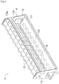
- FIG. 1 is a perspective view showing a configuration of a main frame 2 provided in an automatic winder 1 according to one embodiment of the present invention.
- a side close to the front of the automatic winder may be referred to as the front, and a side close to the back may be referred to as the back.
- the automatic winder 1 mainly includes the main frame 2, a plurality of winding units (winder units) 4,4, ... arranged side by side and mounted to the main frame 2, and a machine controller (not shown).
- the winding units 4,4, ... are arranged side by side in the left-right direction, as seen in a front view.
- each of the winding units 4 unwinds a yarn from a bobbin 6 or a package 7 which are set in a yarn supply exchanging section 3 and winds such yarn to form a package 9.
- FIG. 2 shows an example in which the yarn is unwound from the bobbin 6.
- FIG. 5 shows an example in which the yarn is unwound from the package 7.
- the machine controller is arranged at one end of the main frame 2 in the direction where the plurality of winding units 4, 4, ... are arranged.
- the machine controller communicates with an unit controller 90 provided in each of the winding units 4 and thereby totally controls the winding units 4, 4...
- An operator inputs appropriate commands to the machine controller, which can collectively manage the plurality of winding units 4.
- the main frame 2 is a framework of the automatic winder 1.
- the main frame 2 mainly includes side plate parts (side plates) 11, a bottom plate part 12, a blower duct (duct) 13, a support shaft (compressed air pipe) 14, and a receiving plate (covering member) 15.
- the side plate parts 11 that are plate-like members, are provided in a pair of left and right, with its thickness direction facing the horizontal direction.
- the left and right side plate parts 11 face each other with a space necessary for arranging the plurality of winding units 4, 4,...
- the bottom plate part 12 that is a plate-like member, horizontally connects a lower end portion of the left side plate part 11 and a lower end portion of the right side plate part 11.
- the bottom plate part 12 has a horizontal plate shape elongated in the left-right direction.
- the blower duct 13 for flowing suction flow (suction airflow) generated (sucked) in each of the winding units 4 due to rotation of a fan (not shown) is bridged between the left and right side plate parts 11. Openings 13a formed on a front surface side of the blower duct 13 correspond to the winding units 4, respectively. Each opening 13a is connected, via a pipe etc., to a member in each winding unit 4, specifically, the member subjected to cause suction flow to be generated.
- the receiving plate 15 arranged parallel to an upper surface of the blower duct 13 is arranged above the blower duct 13.
- the receiving plate 15 having a horizontal plate shape elongated in the left-right direction is bridged between the left and right side plate parts 11.
- the receiving plate 15 is slightly spaced in the vertical direction with respect to the upper surface (first receiving surface) of the blower duct 13.
- the receiving plate 15 faces an upper surface of the blower duct 13.
- the receiving plate 15 has one end in the front-back direction of the automatic winder, the one end that is bent downward, so that the receiving plate 15 is supported by the upper surface of the blower duct 13.
- the receiving plate 15 is fixed to the blower duct 13 by welding or the like.
- the receiving plate 15 may have a U-like shape that opens downward as seen from a side surface of one of the winding units 4, and may be fixed to the upper surface of the blower duct 13 having a hexagonal cross section. In this case, when a yarn winding section 5, which will be described later, is mounted on the receiving plate 15, all of the weight of the yarn winding section 5 is supported by the blower duct 13 (the upper surface of the blower duct 13).
- the support shaft 14 having a cross section that is a circular elongated shaft is provided at a position below a front end surface of the blower duct 13.
- the support shaft 14 is horizontally bridged between the left and right side plate parts 11 with its axial line facing the left and right direction. Compressed air to be supplied to the winding units 4 flows through the support shaft 14 made of a hollow tubular member.
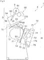
- FIG. 2 is a side view schematically showing an example of a configuration of one of the winding units 4 provided in the automatic winder 1.
- each of the winding units 4 includes a yarn winding section (first module /yarn winding module) 5 arranged at an upper portion of the main frame 2, and a yarn processing section 10 arranged below the yarn winding section 5.
- the yarn processing section 10 includes a yarn supply exchanging section (third module/yarn supply exchanging module) 3 arranged at a lower portion of the main frame 2, and a yarn joining section (second module/yarn joining module) 8 arranged at an intermediate portion of the main frame 2 in the vertical direction.
- each of the winding units 4 is formed by combining three modules, the yarn supply exchanging section 3, the yarn winding section 5, and the yarn joining section 8.
- the yarn supply exchanging section 3 that is a part of the yarn processing section 10 is a section in which a yarn supply bobbin (the bobbin 6 or the package 7) that supplies the yarn to be rewound into the package 9 is set to be exchangeable.
- the yarn supply exchanging section 3 is mounted to the lower portion of the main frame 2 so as to be placed on an upper surface (third receiving surface) of the bottom plate part 12 of the main frame 2. That is, the yarn supply exchanging section 3 is supported by the upper surface of the bottom plate part 12.
- the yarn supply exchanging section 3 is formed by selectively mounting one of several types of yarn supply exchanging devices. To be specific, one of a magazine type bobbin supply device 20, a tray type bobbin supply device 30, and a package supply device 40 can be mounted to the yarn supply exchanging section 3 of this embodiment.
- the yarn winding section 5 is a section for winding a yarn supplied from the yarn supply exchanging section 3 into a core tube (paper tube) to form the package 9.
- the yarn winding section 5 is mounted to the upper portion of the main frame 2 so as to be placed on the receiving plate 15 of the main frame 2 via a vibration absorbing member 59. That is, all of the weight of the yarn winding section 5 is supported by the upper surface of the blower duct 13. In other words, the yarn winding section 5 is supported, on its back side, by the receiving plate 15 from below.
- the yarn winding section 5 is mounted to the main frame 2 via the receiving plate 15 and an appropriate fixing member (for example, bolts 16).
- the receiving plate 15 and the bolts 16 are regarded as a mounting mechanism (first mounting mechanism) for mounting the yarn winding section 5 to the main frame 2.
- the yarn winding section 5 is formed by selectively mounting one of several types of yarn winding devices. To be specific, either one of a traversing drum type yarn winding device 50 or an arm traverse type yarn winding device 60 can be mounted to the yarn winding section 5 of this embodiment.
- the yarn joining section 8 that is a part of the yarn processing section 10 is a section for joining the yarn supplied from the yarn supply exchanging section 3 to the yarn winding section 5.
- the yarn joining section 8 is mounted to the front side surface of the main frame 2 so that the yarn joining section 8 is supported by an upper surface (second receiving surface) of the support shaft 14 of the main frame 2 and so that a back surface of the yarn joining section 8 comes in contact with an front end surface of the blower duct 13. That is, most (more than half) of the weight of the yarn joining section 8 is supported by the upper surface of the support shaft 14. Accordingly, the yarn joining section 8 is mounted to the intermediate portion of the main frame 2 in the vertical direction, specifically, above the yarn supply exchanging section 3 and below and forward of the yarn winding section 5.
- the yarn joining section 8 is fixed to the front end surface of the blower duct 13 via an appropriate fixing member (for example, a bolt 17), in a state where a stay 77 which will be described later is hooked on the support shaft 14.
- the front end surface of the blower duct 13 is a surface facing outward in the blower duct 13.
- a portion for hooking the stay 77 and the bolt 17 are regarded as a mounting mechanism (second mounting mechanism) for mounting the yarn joining section 8 to the main frame 2.
- the mounting mechanism for mounting the yarn joining section 8 to the main frame 2 is different from that for mounting the yarn winding section 5 to the main frame 2.
- the yarn joining section 8 preferably includes a connecting member (fixing member) 78 for connecting to the yarn supply exchanging section 3.
- the connecting member 78 formed at a lower end of the yarn joining section 8 is used for fixing an upper end of the yarn supply exchanging section 3. Accordingly, the upper end of the yarn supply exchanging section 3 that is individually modularized via the connecting member 78 can be fixed to the yarn joining section 8, which can suppress vibration in the yarn supply exchanging section 3.
- the yarn joining section 8 is formed by selectively mounting one of several types of yarn joining mechanisms. To be specific, either one of a suction mouth type yarn joining mechanism 70 or a yarn accumulation type yarn joining mechanism 80 can be mounted to the yarn joining section 8 of this embodiment.
- Each component mounted to the yarn supply exchanging section 3, the yarn winding section 5, and the yarn joining section 8 has a casing (not shown) independent of other components. That is, a casing of the yarn supply exchanging section 3, a casing of the yarn winding section 5, and a casing of the yarn joining section 8 are different from each other.
- Each component that is configured as a module combined in each casing can be mounted to and removed from the main frame 2.
- the main frame 2 is a base material for combining modules such as the yarn supply exchanging section 3, the yarn winding section 5, the yarn joining section 8. The configuration is not limited as long as each module can be mounted and removed.
- FIG. 2 schematically shows a configuration in which the magazine type bobbin supply device 20 is mounted to the yarn supply exchanging section 3, in which the traversing drum type yarn winding device 50 is mounted to the yarn winding section 5, and in which the suction mouth type yarn joining mechanism 70 is mounted to the yarn joining section 8.
- a configuration of each winding unit 4 will be specifically described with reference to an example in which each winding unit 4 is formed by a combination of these three modules.
- the magazine type bobbin supply device 20 mainly includes a bobbin setting part 21, a magazine type bobbin supply mechanism 22, and an unwinding assist device 29.
- the bobbin setting part 21 is adapted to hold the yarn supply bobbin 6 for unwinding the yarn in an upright state, at a predetermined position.
- the magazine type bobbin supply mechanism 22 includes a cylindrical magazine can 23 for which an operator manually supplies the yarn supply bobbin 6.
- the magazine can 23 has a plurality of pockets arranged in a circle. The operator inserts the yarn supply bobbin 6 into such pocket, so that the yarn supply bobbin 6 can be stocked.
- a yarn supply bobbin guide part 24 for dropping the yarn supply bobbin 6 that has fallen from the magazine can 23 diagonally downward and guiding the yarn supply bobbin 6 to the bobbin setting part 21 is provided below the magazine can 23.
- All of the yarn is unwound from the yarn supply bobbin 6 already set in the bobbin setting part 21, and an empty yarn supply bobbin is discharged by a discharge mechanism (not shown). Then, the yarn supply bobbin 6 stocked in the bobbin supply mechanism 22 is dropped into the yarn supply bobbin guide part 24. Thereby, the yarn supply bobbin 6 can be newly set in the bobbin setting part 21.
- the unwinding assist device 29 appropriately controls the size of balloon by coming into movable member contact with the balloon that is formed at an upper portion of the yarn supply bobbin 6 by swinging the yarn unwound from the yarn supply bobbin 6, and thereby assists unwinding of the yarn.
- the bobbin supply mechanism 22 and the unwinding assist device 29 are supported at a bottom portion of the bobbin setting part 21 via a support 28.
- the bobbin setting part 21 (and thus the magazine type bobbin supply device 20), with its bottom portion placed on the bottom plate part 12, is mounted to the main frame 2.
- the traversing drum type yarn winding device 50 mainly includes a winding bobbin 51, a cradle 52, a traversing drum (traverse device) 53, and a yarn winding frame 54.
- the winding bobbin 51 forms the package 9 by winding the yarn supplied from the yarn supply exchanging section 3 into its outer circumference.
- the cradle 52 is adapted to hold the winding bobbin 51 (package 9).
- the traversing drum 53 traverses the yarn and causes the winding bobbin 51 to be rotated.
- the cradle 52 is rotated around a pivot 58, and thereby swings in a direction approaching or separating from the traversing drum 53. Accordingly, the package 9 comes in contact with or separates from the traversing drum 53.
- the pivot 58 of the cradle 52 is arranged within an upper area of the receiving plate 15.
- a traverse groove with a spiral shape is formed on an outer circumferential surface of the traversing drum 53.
- the yarn is wound into the winding bobbin 51 while being traversed by the traverse groove with a certain width. This can form the package 9 with a certain winding width.
- the yarn winding frame 54 is a substantially rectangular member.
- the cradle 52 and the traversing drum 53, arranged on one side in the left and right of the yarn winding frame 54, are supported by the yarn winding frame 54 in a cantilever manner.
- a driving motor (driving source) for the traversing drum 53 is arranged in the yarn winding frame 54.
- a horizontal bottom plate 55 is provided on a bottom part on a back side of the yarn winding frame 54. In a state that the bottom plate 55 placed on the upper surface of the receiving plate 15 via the vibration absorbing member 59, the yarn winding frame 54 (and thus, the yarn winding section 5) is mounted to the main frame 2.
- the yarn winding frame 54 partitions between itself and the yarn winding section 5 of the adjacent winding unit 4.
- the bottom plate 55 can be also formed integrally with the yarn winding frame 54.
- the suction mouth type yarn joining mechanism 70 mainly includes a yarn monitoring device (yarn defect monitoring device) 71, a splicer 72, a lower yarn guide pipe 73, an upper yarn guide pipe 74, a tension applying device (yarn tension applying device) 75, a yarn joining frame 76, and a stay 77.
- the yarn joining frame 76 is a substantially rectangular member elongated in the vertical direction.
- the yarn monitoring device 71, the splicer 72, the lower yarn guide pipe 73, the upper yarn guide pipe 74, and the tension applying device 75 arranged on one side in left and right of the yarn joining frame 76, are supported by the yarn joining frame 76 in a cantilever manner.
- the yarn joining frame 76 is mounted to an intermediate portion of the main frame 2 in the vertical direction, while supporting each above-described component.
- the yarn joining frame 76 is aligned with the yarn winding frame 54 in the left-right direction so as to partition between itself and the yarn joining section 8 of the adjacent winding unit 4.
- the yarn winding frame 54 and the yarn joining frame 76 are not connected directly to each other.
- a gap as a space is formed between the yarn winding frame 54 and the yarn joining frame 76 (in the vertical direction).
- a configuration for mounting the yarn joining frame 76 to the main frame 2 will be specifically described.
- the stay 77 protruding from the back side of the yarn joining frame 76 toward the rear side, is hooked on the support shaft 14.
- the yarn joining frame 76 is then mounted to the main frame 2 such that the back side of the yarn joining frame 76 comes in contact with the front end surface of the blower duct 13 via the vibration absorbing member 79.
- the member subjected to cause suction flow of the yarn joining section 8 and the yarn supply exchanging section 3 to be generated, and each opening 13a of the blower duct 13 shown in FIG. 1 are connected to each other via a pipe, etc.
- the unit controller 90 and the like that is a control section for controlling each component of the winding unit 4, is arranged inside the yarn joining frame 76.
- the yarn monitoring device 71 monitors the thickness of the yarn, and thereby detects the defects such as slabs which occur in the yarn (in the following, may be referred to as yarn defect).
- a cutter for immediately cutting the yarn when the yarn monitoring device 71 detects the yarn defect, is arranged in the vicinity of the yarn monitoring device 71.
- the splicer 72 joins the yarn on the yarn supply exchanging section 3 side and the yarn on the yarn winding section 5 side (performs yarn joining), when the yarn monitoring device 71 detects the yarn defect and then cuts the yarn by the cutter, when yarn breakage occurs during unwinding of the yarn from the yarn supply bobbin 6, when the yarn supply bobbin 6 is exchanged, and the like.
- the splicer 72 of this embodiment is an air splicer in which the yarn is twisted by using a swirl air stream formed using compressed air that is supplied from a compressor (not shown), and then the yarn joining is performed.
- the lower yarn guide pipe 73 for sucking, capturing and guiding a lower yarn on the yarn supply exchanging section 3 side, and the upper yarn guide pipe 74 for sucking, capturing and guiding an upper yarn on the yarn winding section 5 side, are provided on the lower side and the upper side of the splicer 72.
- a suction port is formed at a tip of the lower yarn guide pipe 73.
- a suction mouth is provided at a tip of the upper yarn guide pipe 74.
- the lower yarn guide pipe 73 and the upper yarn guide pipe 74 are connected to each opening 13a of the blower duct 13 via a pipe, etc. This can cause the suction airflow to be generated in the suction port and the suction mouth.
- the suction port of the lower yarn guide pipe 73 rotated downward, sucks and captures the lower yarn. Then, the suction port is rotated upward, which can guide the lower yarn to the splicer 72.
- the suction mouth of the upper yarn guide pipe 74 sucks and captures the upper yarn unwound from the package 9 that is driven in reverse. Then, the suction mouth is turned downward, which can guide the upper yarn to the splicer 72. The yarn joining between the lower yarn and the upper yarn is performed in the splicer 72.
- the winding unit 4 shown in FIG. 2 unwinds the yarn from the yarn supply bobbin 6 set in the yarn supply exchanging section 3, and winds the yarn into the winding bobbin 51, which can form the package 9 with a predetermined length.
- each winding unit 4 includes the unit controller 90 and a winding controller 91.
- the unit controller 90 and the winding controller 91 are configured as a computer.
- the unit controller 90 and the winding controller 91 are configured with hardware such as CPU, ROM, RAM etc., and software such as a control program stored in the ROM and/or the RAM. Collaboration of the hardware and the software allows the winding controller 91 to control a winding operation of the yarn winding section 5.
- the unit controller 90 that is higher order control section than the winding controller 91, controls the winding controller 91, and also totally controls the entire winding unit 4 including the yarn joining section 8 and the yarn supply exchanging section 3.
- the unit controller 90 is adapted to communicate with the above-described machine controller.
- the unit controller 90 and the winding controller 91 are arranged inside the back side of the yarn joining frame 76.
- the back side of the yarn joining frame 76 is spaced from the front end surface of the blower duct 13 and then the yarn joining frame 76 is rotated around the support shaft 14, which can expose a surface for accessing to the unit controller 90 and the winding controller 91, as shown in FIG. 3 .
- the unit controller 90 or the winding controller 91 is taken out of the yarn joining frame 76 and then works such as maintenance and exchanging thereof can be implemented.
- the winding controller 91 is electrically connected to each component of the yarn winding device 50 by connecting a connector 98 provided at a tip of a harness extending from the yarn winding device 50 to a connector 99 in the winding controller 91.
- the winding controller 91 and the unit controller 90 are electrically connected to each other via connectors.
- the unit controller 90 is electrically connected to each component of the yarn joining mechanism 70 by connecting a connector provided at a tip of a harness extending from the yarn joining mechanism 70 to a connector in the unit controller 90.
- the unit controller 90 is electrically connected to each component of the magazine type bobbin supply device 20 by connecting a connector provided at a tip of a harness extending from the magazine type bobbin supply device 20 to a connector in the unit controller 90.
- FIG. 4 schematically shows a configuration in which the transport tray type bobbin supply device 30 is mounted to the yarn supply exchanging section 3.
- FIG. 5 schematically shows a configuration in which the package supply device 40 is mounted to the yarn supply exchanging section 3.
- FIG. 4 schematically shows a configuration in which the arm traverse type yarn winding device 60 is mounted to the yarn winding section 5.
- the operator operates works in accordance with the following procedure, for example. That is, the operator removes the connector provided at the tip of the harness extending from the magazine type bobbin supply device 20, from the connector in the unit controller 90. The operator lifts the magazine type bobbin supply device 20 from the bottom plate part 12, moves the magazine type bobbin supply device 20 to another place, and replaces the transport tray type bobbin supply device 30 on the bottom plate part 12. Then, the operator connects the connector provided at the tip of the harness extending from the transport tray type bobbin supply device 30 to the connector in the unit controller 90.
- the operator removes the connector 98 provided at the tip of the harness extending from the traversing drum type yarn winding device 50 from the connector 99 in the winding controller 91.
- the operator removes the bottom plate 55 of the traversing drum type yarn winding device 50 from the receiving plate 15, and moves the entire yarn winding device 50 into another place.
- the operator also removes the winding controller 91 for the traversing drum type from the yarn joining frame 76, and replaces a controller 93 for the arm traverse type (see FIG. 4 ).
- the controller 93 and unit controller 90 are connected to each other via a connector.
- the controller 93 and the arm traverse type yarn winding device 60 are electrically connected to each other via the connector.
- the arm traverse type yarn winding device 60 is also placed on the receiving plate 15 and mounted thereto.
- a main frame 200 shown in FIG. 6 instead of the above-described main frame 2, is used as the main frame for assembling the plurality of winding units 4,4, ..., which can mount the yarn accumulation type yarn joining mechanism 80 to the yarn joining section 8.
- the main frame 200 is different from the main frame 2 in the position (height) where the blower duct 13 is mounted.
- FIG. 6 schematically shows a configuration in which the yarn accumulation type yarn joining mechanism 80 is mounted to the yarn joining section 8.
- the transport tray type bobbin supply device 30 shown in FIG. 4 mainly includes a bobbin setting part 31, a yarn unwinding assist device 39, and a support 38.
- the bobbin setting part 31 is adapted to hold the yarn supply bobbin 6 for unwinding the yarn in an upright state, at a predetermined position.
- the yarn unwinding assist device 39 appropriately controls the size of balloon by a movable member coming into contact with the balloon that is formed at an upper portion of the yarn supply bobbin 6, and thereby assists unwinding of the yarn.
- the support 38 supports the yarn unwinding assist device 39 at a position above the bobbin setting part 31.
- the bobbin setting part 31 with its bottom portion placed on the bottom plate part 12, (and thus the transport tray type bobbin supply device 30) is mounted to the main frame 2.
- the package supply device 40 shown in FIG. 5 mainly includes package setting parts 41, a rotating arm 42, and a support 48.
- Each of the package setting part 41 that is a shaft-shaped member can be set by inserting a cone-shaped yarn supply package (package 7) for unwinding the yarn.
- the package setting parts 41 are provided in both end portions of the rotating arm 42 that is an elongated plate-like member.
- a center part 44 of the rotating arm 42 is rotatably supported by the support 48.
- the rotating arm 42 is rotated around the center part 44, and thereby the package 7 for unwinding the yarn can be switched to either one of the packages 7 set in the package setting parts 41 on both end portions.
- a bottom portion of the support 48 is placed on the bottom plate part 12, which can mount the package supply device 40 to the main frame 2.
- the arm traverse type yarn winding device 60 shown in FIG. 4 and FIG. 6 mainly includes a winding bobbin 61, a winding bobbin rotation driving source (driving source) (not shown), a cradle 62, a contact roller 63, a yarn winding frame 64, and a traverse arm 67 and a traverse driving motor 66 included in a traverse device.
- the cradle 62 rotatably supports the winding bobbin 61.
- the yarn winding device 60 including the cradle 62, the winding bobbin rotation driving source, and the traverse driving motor 66, etc., are arranged on one side in the left and right of the yarn winding frame 64, and supported by the yarn winding frame 64 in a cantilever manner.
- the traverse arm 67 is driven to reciprocate and swirl by the traverse driving motor 66.
- the contact roller 63 can be rotated while coming in contact with a peripheral surface of the winding bobbin 61.
- the traverse arm 67 is moved in reciprocating and swirling motion as a rotor of the traverse driving motor 66 repeats forward and reverse rotation. Accordingly, the yarn hooked on a tip of the traverse arm 67 is traversed and also wound into the winding bobbin 61 that is driven in rotation, via the contact roller 63. This can form the package 9 in which the package 7 is rewound.
- a horizontal bottom plate 65 is provided at a bottom portion on the back side of the yarn winding frame 64. The bottom plate 65 is placed on the upper surface of the receiving plate 15 and fixed thereto, which can mount the yarn winding device 60 to the main frame 2.
- the yarn accumulation type yarn joining mechanism 80 shown in FIG. 6 once accumulates the yarn supplied from the yarn supply exchanging section 3 with a yarn accumulation part (accumulator) 81, and then winds the yarn into a core tube (paper tube) with the yarn winding section 5 to form the package 9.
- the yarn accumulation part 81 includes a yarn accumulation roller 82 in which the yarn can be wound.
- the yarn joining mechanism 80 mainly includes a splicer 83, a yarn monitoring device 84, a yarn guiding member 85, and a yarn joining frame 86, as other components.
- the yarn supplied from the yarn supply exchanging section 3 is wound into the yarn accumulation roller 82 and temporarily accumulated therein. Thereby, the yarn is wound into the core tube (paper tube) in a state where an appropriate tension is applied to the yarn.
- the yarn monitoring device 84 the yarn is immediately cut by the cutter and divided thereby.
- a lower yarn on the yarn supply exchanging section 3 side is blown up by a lower yarn blowing-up part (not shown) and guided to the splicer 83.
- An upper yarn on the yarn winding section 5 side is guided and taken out by the yarn guiding member 85, and then pulled out from the yarn accumulation roller 82. Then, the yarn is joined by the splicer 83. Thereby, the yarn is reconnected and yarn winding is resumed.
- the yarn accumulation part 81, the splicer 83, the yarn monitoring device 84, and the yarn guiding member 85 are arranged on one side in left and right of the yarn joining frame 86.
- the yarn joining frame 86 supports these members in a cantilever manner.
- the yarn joining frame 86 is aligned with a winding frame (the yarn winding frame 64 in the example in FIG. 6 ) of the yarn winding section 5 in the left-right direction, so as to partition between itself and the yarn joining section 8 of the adjacent winding unit 4.
- the winding frame and yarn joining frame 86 are not connected directly to each other.
- a space is formed between the winding frame and yarn joining frame 86. In other words, the winding frame and the yarn joining frame 86 are spaced from each other in the vertical direction.
- the yarn joining frame 86 is mounted to the yarn joining section 8 such that a stay 87 protruding from the back side of the yarn joining frame 86 is hooked on the support shaft 14 and comes in contact with the front end surface of the blower duct 13.
- a unit controller 94 for the yarn accumulation type yarn joining mechanism is arranged inside the back side of the yarn joining frame 86.
- the size of the yarn joining section 8 in the vertical direction is increased. This is because the yarn accumulation roller 82 for accumulating the yarn requires a space in the vertical direction.
- the dedicated main frame 200 is used as the framework in a case of applying the yarn accumulation type yarn joining mechanism 80 to the yarn joining section 8. Accordingly, the combination of the above-described two types of yarn winding section 5, and the above-described three types of yarn supply exchanging section 3, can easily provide twelve types of winding unit 4.
- the automatic winder 1 of this embodiment adopts a special configuration for protecting the unit controller 90 (94) and the winding controller 91 (93) weak in vibration and impact.
- a configuration for countermeasures against such vibration will be specifically described as follows.
- the automatic winder 1 is assembled by modules as shown in FIG. 2 , however, the same configuration also applies to other examples as shown in FIG. 3 to FIG. 6 .
- the yarn winding section 5 is mounted to the main frame 2 at a position different from a position where the yarn processing section 10 is mounted to the main frame 2.
- the yarn winding section 5 is connected indirectly to the yarn joining section 8 via the main frame 2. Therefore, vibration generated by winding the yarn in the yarn winding section 5 is transmitted to the yarn joining section 8 only via main frame 2.
- the unit controller 90 and the winding controller 91 typically weak in vibration and impact can be protected from vibration.
- the yarn monitoring device 71, the splicer 72 and the tension applying device 75 arranged in the yarn joining section 8 in order from a side closest to the yarn winding section 5, can also be protected from vibration of the yarn winding section 5.
- the yarn monitoring device 71 that is a device for sensing and typically weak in vibration, even so, is arranged in the vicinity of the yarn winding section 5. With a configuration of this embodiment, the yarn monitoring device 71 can also be well protected from vibration.
- the vibration absorbing member 59 is arranged between the bottom plate 55 of the yarn winding frame 54 and the receiving plate 15.
- the vibration absorbing member 79 is arranged between the back side of the yarn joining frame 76 and the blower duct 13. Furthermore, the yarn winding section 5 and the yarn joining section 8 are arranged with a gap (space) in the vertical direction. This can efficiently reduce transmission of vibration along with a winding operation of the yarn in the yarn winding section 5 to the unit controller 90 and the winding controller 91 of the yarn joining section 8. Similarly, transmission of vibration to the yarn monitoring device 71, the splicer 72, and the tension applying device 75 is also effectively suppressed.
- the simplest layout of the textile machine, in its upper portion, having a yarn winding section is a configuration in which the yarn winding section is fixed to an upper surface of a blower duct that is a main structure of the main frame.
- the yarn joining section 8 since the yarn joining section 8 is fixed to the blower duct 13, vibration along with rotation of the package 9 in the yarn winding section 5 is easily transmitted to the yarn joining section 8 via the blower duct 13.
- the yarn winding section 5 (specifically, the bottom plate 55 of the yarn winding frame 54) is supported not on the upper surface of the blower duct 13, but on the upper surface of the receiving plate 15 spaced upward from the blower duct 13. With this configuration, vibration transmitted to the yarn joining section 8 can be suppressed, which can protect the unit controller 90 inside the yarn joining section 8.
- a vibration source of the yarn winding section 5 is arranged at a position (a position where the winding bobbin 61 or the package 9 comes in contact with the contact roller 63) forward of a back side position (a mating surface between the bottom plate 55 and the receiving plate 15) where the yarn winding section 5 is supported by the main frame 2.
- a layout in which a front surface of the yarn winding section 5 is aligned with a front surface of the yarn joining section 8 in the front-rear direction, by making the amount in which the yarn winding section 5 protrudes forward (frontward) equal to the amount in which the yarn joining mechanism 70 protrudes forward.
- the front surface of the yarn winding section 5 is positioned rearward of the front surface of the yarn joining section 8 by a distance P. This can reduce the amount in which the yarn winding section 5 overhangs forward and also reduce looseness of the bottom plate 55. Accordingly, vibration transmitted to the main frame 2 (and thus the unit controller 90) can be suppressed.
- the pivot 58 of the cradle 52 to which vibration generated on the vibration source of the yarn winding section 5 (at a position where the winding bobbin 61 or the package 9 comes in contact with the contact roller 63) is directly transmitted is arranged in an upper region of the receiving plate 15 (a region supported from below), not in a region where the yarn winding section 5 overhangs. This can stably hold a position of the pivot 58 and reduce unstable placement of the pivot 58. Accordingly, looseness of the bottom plate 55 can be suppressed, and vibration transmitted to the main frame 2 (and thus the unit controller 90) can be suppressed.
- the automatic winder 1 of this embodiment winds the yarn from the yarn supply bobbin 6 to form the package 9.
- the automatic winder 1 includes the plurality of winding units 4, and the main frame 2.
- Each of the plurality of winding units 4 includes at least the yarn winding section 5 and the yarn joining section 8.
- the main frame 2 has the plurality of winding units 4.
- the main frame 2 has an upper surface of the blower duct 13 and an upper surface of the support shaft 14.
- the upper surface of the blower duct 13 that is an upward surface, supports more than half the weight of the yarn winding section 5.
- the upper surface of the support shaft 14 that is an upward surface supports more than half the weight of the yarn joining section 8.
- the yarn winding section 5 winds the yarn into the package 9.
- the yarn joining section 8 joins the yarn.
- the yarn winding section 5 and the yarn joining section 8 are mounted to the main frame 2 via a different mounting mechanism, respectively.
- each module can be stably supported on the upward surfaces, and also each module conventionally integrated can be individually mounted to the main frame 2.
- Each module is more compact and lighter than the entire winder unit 4, which can improve mounting workability.
- each winding unit 4 includes the yarn supply exchanging section 3.
- the main frame 2 has an upper surface of the bottom plate part 12.
- the upper surface of the bottom plate part 12 that is an upward surface, supports more than half of the weight of the yarn supply exchanging section 3.
- the yarn supply exchanging section 3 holds the yarn wound in the yarn winding section 5.
- the yarn supply exchanging section 3 as a yarn supply exchanging module can be individually mounted, which can further improve mounting workability.
- the yarn joining section 8 includes the connecting member 78 for fixing the yarn supply exchanging section 3.
- the yarn supply exchanging section 3 is fixed to the yarn joining section 8, which can suppress vibration of the yarn supply exchanging section 3.
- the main frame 2 includes the blower duct 13 and the support shaft 14 having a tubular shape that functions as a pipe.
- the suction airflow sucked from the winder units 4 flows through the blower duct 13.
- the tubular support shaft 14 supplies compressed air to the winding units 4.
- the upper surface of the blower duct 13 supports more than half of the weight of the yarn winding section 5.
- the upper surface of the support shaft 14 supports more than half of the weight of the yarn joining section 8.
- surfaces of other functional members can be used to support the weight of the yarn winding section 5 and the weight of the yarn joining section 8, which can reduce the cost and simplify the structure.
- the yarn winding section 5 shown in FIG. 2 includes the cradle 52, the drive motor, and the traversing drum 53.
- the yarn winding section 5 shown in FIG. 4 includes the cradle 62, the driving motor, the traverse arm 67, and the traverse driving motor 66.
- the cradles 52, 62 rotatably support the package 9.
- the driving motor generates a driving force for rotating the package 9.
- the traversing drum 53 in FIG. 2 included in the traverse device traverses the yarn wound into the package 9.
- the traverse arm 67 and the traverse driving motor 66 in FIG. 4 included in the traverse device traverses the yarn wound into the package 9.
- the devices for forming the package 9 can be combined into one module.
- the yarn winding section 5 can be exchanged without affecting other modules.
- the yarn winding section 5 is mounted to the receiving plate 15 provided on the upper surface of the blower duct 13.
- the yarn winding section 5 can be mounted without forming a mounting hole for mounting the yarn winding section 5 on the upper surface of the blower duct 13.
- a configuration in which the upper surface of the blower duct 13 supports most of the weight of the yarn winding section 5, can be achieved.
- the upper surface of the blower duct 13 facing upward supports all of the weight of the yarn winding section 5.
- the upper surface of the support shaft 14 is provided downward of the blower duct 13 which flows suction flow sucked from the winding units 4.
- the yarn joining section 8 supported on the upper surface of the support shaft 14 is mounted to the front end surface that is a surface facing outward in the blower duct 13.
- the yarn joining section 8 is mounted via two portions positioned in the vertical direction, which can preferably fix the yarn joining section 8.
- the yarn winding section 5 is provided upward and rearward of the yarn joining section 8.
- the yarn joining section 8 is provided upward of the yarn supply exchanging section 3 that holds the yarn wound in the yarn winding section 5.
- the automatic winder 1 that causes the yarn to run upward from downward can be configured.
- the automatic winder 1 of this embodiment includes the main frame 2 as a base member, and the yarn supply exchanging section 3.
- the yarn supply exchanging section 3 is arranged at a lower portion of the main frame 2.
- One of several types of the yarn supply exchanging devices 20, 30, 40 is selectively mounted to the yarn supply exchanging section 3.
- the yarn winding section 5 is arranged at an upper portion of the main frame 2.
- One of several types of the yarn winding devices 50, 60 is selectively mounted to the yarn winding section 5.
- the yarn joining section 8 arranged at an intermediate portion of the main frame 2 in the vertical direction, joins the yarn supplied from the yarn supply exchanging section 3 to the yarn winding section 5.
- each component is modularly managed to easily form several types of the winding units 4. Furthermore, mixed production and batch production can be easily implemented in the automatic winder 1 having the plurality of winding units 4,4,... This can achieve reduction of the number of devices as a whole textile machine equipment with the automatic winder 1, manpower-saving, and cost reduction thereby.
- the yarn supply exchanging device is the magazine type bobbin supply device 20, and the transport tray type bobbin supply device 30.
- the yarn winding device is the traversing drum type yarn winding device 50, and the arm traverse type yarn winding device 60.
- the yarn supply exchanging device the magazine type bobbin supply device 20, the transport tray type bobbin supply device 30, and the package supply device 40 for supporting the cone-shaped package 7.
- the yarn winding device is the traversing drum type yarn winding device 50, and the arm traverse type yarn winding device 60.
- a combination of the yarn supply exchanging devices 20,30,40 and the yarn winding devices 50,60 is varied, which can easily provide six types of winding units 4.
- either one of several types of the yarn joining mechanisms 70,80 is selectively mounted to the yarn joining section 8.
- the yarn supply exchanging device is the magazine type bobbin supply device 20, and the transport tray type bobbin supply device 30.
- the yarn winding device is the traversing drum type yarn winding device 50, and the arm traverse type yarn winding device 60.
- the yarn joining mechanism is the suction mouth type yarn joining mechanism 70, and the yarn accumulation type yarn joining mechanism 80 having the yarn accumulation part 81.
- a combination of the yarn supply exchanging devices 20,30, the yarn winding devices 50,60, and the yarn joining mechanisms 70,80 is varied, which can easily provide six or more types of winding units 4.
- either the traversing drum type yarn winding device 50 or the arm traverse type yarn winding device 60 can be selected as the yarn winding device to be mounted to the yarn winding section 5.
- the automatic winder 1 of this embodiment includes the main frame 2 as a base member, and the yarn supply exchanging section 3.
- the yarn supply exchanging section 3 is removably provided at a lower portion of the main frame 2.
- the yarn winding section 5 is removably mounted above a position where the yarn supply exchanging section 3 is provided.
- the yarn joining section 8 is removably mounted, in the main frame 2, above a position where the yarn supply exchanging section 3 is provided, and below a position where the yarn winding section 5 is mounted.
- each of the yarn supply exchanging section 3, the yarn winding section 5, and the yarn joining section 8 can be mounted or removed as a module.
- This can easily implement mixed production and batch production in the automatic winder 1 having the plurality of winding units 4, 4.... This can achieve reduction of the number of devices as a whole textile machine equipment with the automatic winder 1, manpower-saving, and cost reduction thereby.
- the yarn supply exchanging section 3, the yarn winding section 5, and the yarn joining section 8 can be individually mounted or removed, maintenance and inspection, etc., can be implemented for each module. This can improve work efficiency. Specifically, for example, operation can be checked by temporarily connecting the yarn winding section 5, the yarn joining section 8, and the yarn supply exchanging section 3 prepared for each module to a winding controller for inspection (not shown) or an unit controller for inspection (not shown).
- the yarn joining section 8 includes a winding controller 91 (93) for controlling the yarn winding section 5.
- the yarn joining section 8 includes a unit controller 90 for controlling the winding controller 91 (93) and totally controlling the yarn joining section 8 and the yarn supply exchanging section 3.
- the unit controller 90 mainly controls the yarn winding section 5 and the yarn supply exchanging section 3 positioned above or below the unit controller 90. This leads to a simple and rational flow of control signals therebetween.
- the yarn winding section 5 is connected indirectly to the yarn joining section 8 via the main frame 2.
- the yarn winding section 5 in which large vibration is likely to occur along with winding of the yarn is not connected directly to the yarn joining section 8, which can suppress transmission of vibration of the yarn winding section 5 to the unit controller 90 and the winding controller 91 included in the yarn joining section 8.
- the control components weak in vibration and impact can be protected.
- the automatic winder 1 of this embodiment includes the main frame 2, the yarn winding section 5, the yarn processing section 10, and the unit controller 90.
- the yarn winding section 5 is mounted to the main frame 2.
- the yarn processing section 10 including a mechanism for joining the yarn is mounted to the main frame 2 at a position different from a position where the yarn winding section 5 is mounted to the main frame 2.
- the unit controller 90 arranged in the yarn processing section 10, controls the yarn winding section 5 and the yarn processing section 10.
- the yarn winding section 5 in which large vibration occurs along with winding of the yarn is mounted to the main frame 2, at a position different from a position where the yarn processing section 10 is mounted to the main frame 2.
- This can reduce a direct transmission of vibration from the yarn winding section 5 to the yarn processing section 10.
- the unit controller 90 typically weak in vibration, and impact can be protected from vibration and stability of control can be ensured.
- the winding controller 91 as a subordinate controller of the unit controller 90, the winding controller 91 for controlling the yarn winding operation of the yarn winding section 5, is arranged in the yarn processing section 10 together with the unit controller 90.
- the winding controller 91 as the control section of the yarn winding section 5 can be protected from vibration, which can stably implement winding of the yarn.
- the yarn winding section 5 is mounted to an upper portion of the main frame 2.
- the yarn processing section 10 includes the yarn supply exchanging section 3 and the yarn joining section 8.
- the yarn supply exchanging section 3 is arranged at a lower portion of the main frame 2.
- each of the yarn winding section 5, the yarn supply exchanging section 3, and the yarn joining section 8 is modularly configured, which can suppress transmission of large vibration occurred in the yarn winding section 5 to other modules 3, 8.
- the yarn winding section 5 includes the yarn winding frame 54.
- the yarn joining section 8 of the yarn supply exchanging section 3 includes the yarn joining frame 76.
- the yarn winding frame 54 and the yarn joining frame 76 spaced from each other, are mounted to the main frame 2.
- the unit controller 90 can be protected from vibration.
- the cradle 52 for supporting the package 9 that winds the yarn is mounted to the yarn winding frame 54.
- vibration of the cradle 52 is not transmitted directly to the yarn joining frame 76, which can protect the unit controller 90 from vibration.
- the yarn monitoring device 71 for monitoring yarn defect is mounted to the yarn joining frame 76.
- the air splicer 72 for joining the yarn by using a swirl air stream is mounted to the yarn joining frame 76.
- the splicer 72 can be protected from vibration.
- the tension applying device (yarn tension applying device) 75 for applying tension to the yarn is mounted to the yarn joining frame 76.
- the tension applying device 75 can be protected from vibration.
- a space is formed between the yarn winding section 5 and the yarn processing section 10.
- a position (an upper surface of the receiving plate 15) where the yarn winding section 5 is mounted to the main frame 2 is arranged above a position (the support shaft 14) where the yarn processing section 10 is mounted to the main frame 2.
- the yarn winding section 5 and the yarn processing section 10 can be rationally arranged.
- the vibration absorbing members 59, 79 for absorbing vibration are provided between the yarn winding section 5 and the main frame 2 and between the yarn processing section 8 (10) and the main frame 2.
- the main frame 2 arranged horizontally across the pair of side plate parts (side plates) 11, includes the blower duct 13 that passes a suction airflow generated in the yarn processing section 10.
- the yarn processing section 10 (specifically, the yarn joining section 8) is fixed to the blower duct 13.
- the bottom plate (bottom portion) 55 on the back side of the yarn winding section 5 is fixed to the receiving plate 15 bridged between the side plates 11 and arranged above the blower duct 13.
- the yarn winding section 5 is placed on the receiving plate 15 arranged above the blower duct 13, not on an upper surface of the blower duct 13, and then fixed thereto.
- the yarn winding section 5 is supported from below, at a position close to the vibration source of the yarn winding section 5 (a position where the yarn winding is implemented). Therefore, the yarn winding section 5 can be further stably supported, and thus the unit controller 90 can be protected from vibration. This can improve control stability.
- the yarn winding section 5 includes the cradle 52 for supporting the package 9 that is formed by winding the yarn supplied from the yarn processing section 10.
- the pivot 58 of the cradle 52 is arranged above the receiving plate 15.
- the pivot 58 of the cradle 52 is positioned in an upper area of the receiving plate 15. This can suppress unstable placement of the pivot 58. Therefore, the unit controller 90 can be efficiently protected from vibration, and stability of control can be improved.
- a position where the cradle 52 supports the package 9 is arranged on a front side of the yarn winding section 5, rather than a position where the yarn winding section 5 is fixed to the receiving plate 15.
- the front side of the yarn winding section 5 is positioned rearward of the front side of the yarn processing section 10.
- the front side of the yarn winding frame 64 is positioned rearward of the front side of the yarn joining frame 76.
- the amount of protruding to the front (the amount of overhang) is reduced to further suppress looseness of the receiving plate 15. As a result, stability of control can be improved.
- the automatic winder 1 is manufactured by the following method. That is, such method for manufacturing an automatic winder is a method for manufacturing the automatic winder 1 including the plurality of winding units 4 each having at least the yarn winding section 5 and the yarn joining section 8, and the main frame 2 arranged across the plurality of winding units 4.
- the method for manufacturing the automatic winder 1 includes a first supporting step and a second supporting step.
- an upper surface of the blower duct 13 facing upward and included in the main frame 2 supports more than half of the weight of the yarn winding section 5 for winding the yarn into the package 9.
- an upper surface of the support shaft 14 facing upward and included in the main frame 2 supports more than half of the weight of the yarn joining section 8 for joining the yarn.
- the yarn winding section 5 to be supported in the first supporting step and the yarn joining section 8 to be supported in the second supporting step are mounted to the main frame 2 via a different mounting mechanism, respectively.
- each module (the yarn winding section 5 and the yarn joining section 8) can be stably supported on each surface facing upward, and also each module can be individually mounted to the main frame 2.
- Each module is lighter than the entire winding unit 4, which can improve mounting workability.
- the method for manufacturing the automatic winder 1 of this embodiment includes a main frame placement step, a first step, a second step, and a third step.
- the main frame placement step the main frame 2 that is the base member is arranged in an installation position in a textile machine factory, for example.
- the removable yarn supply exchanging section 3 selected from several types of sections is provided at a lower portion of the main frame 2.
- the removable yarn winding section 5 selected from several types of sections is mounted to an upper portion of the main frame 2.
- the removable yarn joining section 8 is mounted to the intermediate portion of the main frame 2 in the vertical direction.
- the first supporting step is implemented as one of the first step, the second step, and the third step.
- the second supporting step is implemented as one of the first step, the second step, and the third step.
- each of the yarn supply exchanging section 3, the yarn winding section 5, and the yarn joining section 8 is modularized and assembled to the main frame 2.
- This can easily manufacture the automatic winder 1.
- inspection can be also implemented in a module unit.
- the yarn winding section 5 prepared for each module for example, can be temporarily connected to a winding controller for inspection (not shown) to check the operation.
- each section is removable, maintenance and inspection, etc., can be implemented for each section as necessary. This can improve work efficiency.
- the splicer 72, the tension applying device (yarn tension applying member) 75, and the yarn monitoring device 71 that are pre-assembled with the yarn joining mechanism 70 are mounted to the yarn joining section 8 each winding unit 4.
- the splicer 83 and the yarn monitoring device 84 that are pre-assembled with the yarn joining mechanism 80 are mounted to the yarn joining section 8 of each winding unit 4.
- the splicers 72,83, the tension applying device 75, and the yarn monitoring devices 71,84 that are regarded as additional functional devices, can be appropriately mounted to and removable from the yarn joining mechanisms 70,80.
- the additional functional devices are not limited to the above-described splicers 72,83, the tension applying device 75, and the yarn monitoring devices 71,84.
- a waxing (wax applying device) or a yarn speed sensor (yarn speed measuring device) may also be adopted as the additional functional devices. That is, various members necessary for winding the yarn can be included in the additional functional devices.
- the additional functional devices necessary for winding operation of the yarn are removably mounted to at least one of the yarn supply exchanging section 3, the yarn winding section 5, or the yarn joining section 8.
- the above-described additional functional devices are at least one of the splicers 72,83, the tension applying device 75, the waxing, the yarn monitoring devices 71,84, and the yarn speed sensor.
- the configuration of the automatic winder 1 can be appropriately changed by mounting the suitable additional functional devices.
- the yarn joining mechanism 80 can be combined with other modules, but this is not limited thereto.
- the yarn joining mechanism 80 may be applied to the main frame 2 by appropriately expanding the space L between the receiving plate 15 and the upper surface of the blower duct 13.
- the common main frame 2 can be used as a framework when applying the yarn joining mechanism 70 to the yarn joining section 8 and when applying the yarn joining mechanism 80 to the yarn joining section 8, which can further promote platform establishment.
- the main frame 2 is a base member for combining the modules such as the yarn supply exchanging section 3, the yarn winding section 5, the yarn joining section 8, etc. As long as each module can be removable, the structure is not limited.
- the vertical dimension of the yarn joining section 8 arranged at the intermediate portion of the automatic winder 1 is changed.
- the mounting position of the yarn winding section 5 can be changed, and various configurations of the winding units 4 can be achieved with a common platform.
- the unit controller 90 and the winding controller 91 are arranged in the yarn joining section 8, but this is not limited thereto. That is, the unit controller 90 and the winding controller 91 may be arranged in the yarn supply exchanging section 3, instead of the yarn joining section 8.
- the yarn joining section 8 and the yarn supply exchanging section 3 may be integrally provided.
- the vibration absorbing member 59 is provided between the yarn winding section 5 (bottom plate 55) and the main frame 2, and the vibration absorbing member 79 is provided between the yarn joining section 8 (yarn joining frame 76) and the front end surface of the blower duct 13, but either one or both of them may be omitted.
- a space is formed between the yarn winding section 5 and the yarn joining section 8, but this is not limited thereto.
- a vibration absorbing member such as a sponge may be provided in the space.
Landscapes
- Engineering & Computer Science (AREA)
- Textile Engineering (AREA)
- Replacing, Conveying, And Pick-Finding For Filamentary Materials (AREA)
Abstract
Description
- The present invention relates to an automatic winder and a method for manufacturing the automatic winder.
- The automatic winder for rewinding a spun yarn to form a package has been conventionally known.
Patent Document 1 discloses this kind of automatic winder. The textile machine ofPatent Document 1 includes a plurality of spinning places (units). Each of the spinning places includes one can feeding means, one spinning unit, and one winding up unit. The spinning unit and/or the winding up unit are configured according to a modular concept, and they are exchangeable.Patent Document 1 discloses that, with the textile machine having the above-described configuration, downtimes due to failures of machine components of the spinning place or during refitting of the spinning place can be minimized. - Patent Document 1: Japanese Patent Application Laid-Open No.
2004-169264 - In the textile machine of the above-described
Patent Document 1, in response to diversification (difference in a winding type, a yarn feeding type, etc.) of the plurality of spinning places (units) provided in the textile machine and needs of improvement of mounting workability in maintenance, etc., each component for each unit has modularized. - The present invention has been made in view of the circumstances described above, and an object of the present invention is to stably support a plurality of modules each included in the winder units, and easily provide several types of automatic winder.
- Problems to be solved by the present invention are as described above, and next, means for solving the problems and effects thereof will be described.
- According to the first aspect of the present invention, an automatic winder with the following configuration is provided. That is, the automatic winder winds a yarn from a yarn supply bobbin to form a package. The automatic winder includes a plurality of winder units and a base member. Each of the winder units has at least a first module and a second module. Each of the winder units is arranged in the base member. The base member has a first receiving surface facing upward and a second receiving surface facing upward. The first receiving surface supports more than half of the weight of the first module. The second receiving surface supports more than half of the weight of the second module. The first module is a yarn winding module configured as a yarn winding section for winding the yarn into the package. The second module is a yarn joining module configured as a yarn joining section for joining the yarn. The first module and the second module are mounted to the base member via a different mounting mechanism, respectively.
- Accordingly, each module can be stably supported on each surface facing upward, and also each module that has been conventionally integrated therewith can be individually mounted to the base member. Each module is more compact and lighter than the entire winder unit, which can improve mounting workability.
- The automatic winder is preferably configured as follows. That is, each of the winder units has a third module. The base member has a third receiving surface that faces upward and supports more than half of the weight of the third module. The third module is a yarn supply exchanging module configured as a yarn supply exchanging section for holding a yarn wound in the yarn winding section.
- Accordingly, the yarn supply exchanging module can be also individually mounted, which can further improve mounting workability.
- In the automatic winder, the yarn joining module preferably includes a fixing member for fixing the yarn supply exchanging module.
- The yarn supply exchanging module is fixed to the yarn joining module, which can suppress vibration of the yarn supply exchanging module.
- The automatic winder is preferably configured as follows. That is, the base member includes a duct and a compressed air pipe. A suction airflow sucked from the winder units flows through the duct. The compressed air pipe supplies compressed air to the winder units. The first receiving surface is formed in the duct. The second receiving surface is formed in the compressed air pipe.
- Accordingly, surfaces on other functional members are diverted as the first receiving surface and the second receiving surface, which can reduce costs and simplify structure.
- The automatic winder is preferably configured as follows. That is, the yarn winding module includes a cradle, a driving source, and a traverse device. The cradle supports the package in a rotatable manner. The driving source generates driving force for rotating the package. The traverse device traverses the yarn to be wound in the package.
- Accordingly, devices relating to formation of the package can be combined into one module. The yarn winding module can be exchanged without affecting other modules.
- In the automatic winder, the yarn winding module is preferably mounted to a covering member provided in the first receiving surface.
- Accordingly, the yarn winding module can be mounted without forming a mounting hole for mounting the yarn winding module on the first receiving surface. This can achieve a configuration in which the first receiving surface can support more than half of the weight of the yarn winding module.
- In the automatic winder, the first receiving surface facing upward preferably supports all of the weight of the yarn winding module.
- Accordingly, there is no need to provide other members for supporting the yarn winding module. This can simplify a configuration of the automatic winder.
- The automatic winder is preferably configured as follows. That is, the second receiving surface is provided downward of the duct through which the suction airflow sucked from the winder units flows. The yarn joining module supported by the second receiving surface is mounted on a surface facing outward in the duct.
- Accordingly, the yarn joining module can be suitably fixed by mounting the yarn joining module via two portions positioned in the vertical direction.
- The automatic winder is preferably configured as follows. That is, the yarn winding module is provided upward and rearward of the yarn joining module. The yarn joining module is provided upward of the yarn supply exchanging module configured as a yarn supply exchanging section for holding a yarn to be wound in the yarn winding section.
- Accordingly, the automatic winder that causes the yarn to run upward from downward can be provided.
- The automatic winder is preferably configured as follows. That is, the base member is a main frame. The automatic winder includes a yarn supply exchanging section that is arranged at a lower portion of the main frame, the yarn supply exchanging section including one of several types of yarn supply exchanging devices that is selectively mounted. The yarn winding section arranged at an upper portion of the main frame, includes one of several types of yarn winding devices that is selectively mounted. The yarn joining section arranged in an intermediate portion of the main frame in the vertical direction joins a yarn supplied from the yarn supply exchanging section to the yarn winding section.
- Accordingly, by appropriately selecting one of the yarn supply exchanging devices mounted to the yarn supply exchanging section and appropriately selecting one of the yarn winding devices mounted to the yarn winding section, each component can be handled as a module to easily provide several types of winding units. Furthermore, mixed production and batch production can be easily implemented in the automatic winder having the plurality of winding units. This can achieve reduction of the number of devices as a whole textile machine equipment with the automatic winder, manpower-saving, and cost reduction thereof.
- The automatic winder is preferably configured as follows. That is, the yarn supply exchanging devices are a magazine type bobbin supply device, and a transport tray type bobbin supply device. The yarn winding devices are a traversing drum type yarn winding device, and an arm traverse type yarn winding device.
- Accordingly, a combination of the yarn supply exchanging device and the yarn winding device is varied, which can easily provide four types of winding units.
- The automatic winder is preferably configured as follows. That is, the yarn supply exchanging devices are a magazine type bobbin supply device, a transport tray type bobbin supply device, and a package supply device for supporting a cone-shaped package. The yarn winding devices are a traversing drum type yarn winding device, and an arm traverse type yarn winding device.
- Accordingly, a combination of the yarn supply exchanging device and the yarn winding device is varied, which can easily provide six types of winding units.
- The automatic winder is preferably configured as follows. That is, one of several types of yarn joining mechanisms is selectively mounted to the yarn joining section. The yarn supply exchanging devices are a magazine type bobbin supply device, and a transport tray type bobbin supply device. The yarn winding devices are a traversing drum type yarn winding device, and an arm traverse type yarn winding device. The yarn joining mechanisms are a suction mouth type yarn joining mechanism, and a yarn accumulation type yarn joining mechanism having a yarn accumulation part.
- Accordingly, a combination of the yarn supply exchanging device, the yarn winding device, and the yarn joining mechanism is varied, which can easily provide six types of winding units.
- In the automatic winder, when the yarn accumulation type yarn joining mechanism is mounted to the yarn joining section, it is preferable that either the traversing drum type yarn winding device or the arm traverse type yarn winding device can be selected as the yarn winding device to be mounted to the yarn winding section.
- Accordingly, a combination of the yarn supply exchanging device, the yarn winding device, and the yarn joining mechanism is varied, which can easily provide eight types of winding units.
- In the automatic winder, it is preferable that an additional functional device necessary for winding the yarn is removably provided in at least one of the yarn supply exchanging section, the yarn winding section, or the yarn joining section.
- Accordingly, coupled with not only a combination of the yarn supply exchanging section, the yarn winding section, and the yarn joining section, but also a combination of the additional functional device, various types of winding units can be easily provided.
- In the automatic winder, the functional device is preferably at least one of an air splicer, a yarn tension applying device, a wax applying device, a yarn defect monitoring device, and a yarn speed measuring device.
- Accordingly, a configuration of the automatic winder can be appropriately changed by mounting a suitable functional device according to an application of the winding units.
- The automatic winder is preferably configured as follows. That is, the base member is a main frame. The automatic winder includes a yarn supply exchanging section removably provided at a lower portion of the main frame. The yarn winding section is removably mounted, in the main frame, above a position where the yarn supply exchanging section is provided. The yarn joining section is removably mounted, in the main frame, above a position where the yarn supply exchanging section is provided, and below a position where the yarn winding section is mounted.
- Accordingly, each of the yarn supply exchanging section, the yarn winding section, and the yarn joining section can be mounted or removed as a module. This can easily implement mixed production and batch production in the automatic winder having the plurality of winding units. This can achieve reduction of the number of devices as a whole textile machine equipment with the automatic winder, manpower-saving, and cost reduction thereof. Furthermore, since the yarn supply exchanging section, the yarn winding section, and the yarn joining section can be individually mounted or removed, works such as maintenance and inspection can be implemented for each module. This can improve work efficiency.
- In the automatic winder, it is preferable that the height of a mounting position of the yarn winding section with respect to the main frame can be changed.
- Depending on whether a type of sections including a yarn accumulation device or a type of sections without a yarn accumulation device is adopted as the yarn joining section, for example, the dimension of the yarn joining section in the vertical direction that is positioned in an intermediate portion of the automatic winder is varied. In this respect, according to this configuration, the mounting position of the yarn winding section can be changed in accordance with change in the height of the yarn joining section. This can achieve various organization of the winding units.
- The automatic winder is preferably configured as follows. That is, the yarn joining section includes a winding controller for controlling the yarn winding section. The yarn joining section includes an unit controller for controlling the winding controller and totally controlling the yarn joining section and the yarn supply exchanging section.
- Accordingly, the unit controller mainly controls the yarn winding section and the yarn supply exchanging section positioned above or below the unit controller. This leads to a simple and rational flow of control signals therebetween.
- The automatic winder is preferably configured as follows. That is, the base member is a main frame. The yarn winding section is mounted to the main frame. The automatic winder includes a yarn processing section and an unit controller. The yarn processing section, including a mechanism for joining the yarn, is mounted to the main frame at a position different from the position where the yarn winding section is mounted to the main frame. The unit controller arranged in the yarn processing section controls the yarn winding section and the yarn processing section.
- Accordingly, the yarn winding section in which a large vibration occurs along with winding of the yarn is mounted to the main frame, at a position different from the position where the yarn processing section is mounted to the main frame. This can reduce a direct transmission of vibration from the yarn winding section to the yarn processing section. Thus, the unit controller typically weak in vibration and impact can be protected from vibration, and stability of control can be ensured.
- The automatic winder is preferably configured as follows. That is, the yarn winding section is mounted to an upper portion of the main frame. The yarn supply exchanging section is arranged at a lower portion of the main frame. The yarn joining section arranged between the yarn supply exchanging section and the yarn winding section is adapted to join a yarn supplied from the yarn supply exchanging section to the yarn winding section. The yarn processing section includes the yarn supply exchanging section and the yarn joining section.
- Accordingly, each of the yarn winding section, the yarn supply exchanging section, and the yarn joining section is modularly configured, which can suppress transmission of large vibrations occurred in the yarn winding section to other modules.
- The automatic winder is preferably configured as follows. That is, the yarn winding section includes a yarn winding frame. The yarn joining section of the yarn supply exchanging section includes a yarn joining frame. The yarn winding frame and the yarn joining frame spaced from each other are mounted to the main frame.
- Accordingly, even when the yarn winding frame greatly vibrates along with winding of the yarn, such vibration is not transmitted directly to the yarn joining frame. Therefore, the unit controller can be protected from vibration.
- In the automatic winder, it is preferable that a cradle for supporting a package that winds a yarn is mounted to the yarn winding frame.
- Accordingly, since vibration of the cradle is not transmitted directly to the yarn joining frame, the unit controller can be protected from vibration.
- In the automatic winder, it is preferable that a yarn defect monitoring device for monitoring yarn defects is mounted to the yarn joining frame.
- Accordingly, the yarn defect monitoring device typically weak in vibration can be protected from vibration. Therefore, a yarn sensing by the yarn defect monitoring device can be implemented with high accuracy.
- In the automatic winder, it is preferable that an air splicer for joining the yarn by using a swirl air stream is mounted to the yarn joining frame.
- Accordingly, the air splicer can be protected from vibration.
- In the automatic winder, it is preferable that a yarn tension applying device for applying tension to the yarn is mounted to the yarn joining frame.
- Accordingly, the yarn tension applying device can be protected from vibration.
- In the automatic winder, it is preferable that a space is formed between the yarn winding section and the yarn processing section.
- This can efficiently suppress transmission of large vibrations occurred in the yarn winding section to the yarn processing section. Therefore, an adverse effect on the unit controller due to vibration can be reduced.
- In the automatic winder, it is preferable that a position where the yarn winding section is mounted to the main frame is arranged above a position where the yarn processing section is mounted to the main frame.
- Accordingly, the yarn winding section and the yarn processing section can be rationally arranged.
- In the automatic winder, it is preferable that a vibration absorbing member for absorbing vibration is provided at least either between the yarn winding section and the main frame or between the yarn processing section and the main frame.
- This can more reliably suppress transmission of vibration in the yarn winding section to the unit controller of the yarn processing section.
- The automatic winder is preferably configured as follows. That is, the main frame bridged horizontally between a pair of side plates includes a duct through which a suction airflow generated in the yarn processing section passes. The yarn processing section is fixed to the duct. A bottom portion on the back side of the yarn winding section is fixed to a receiving plate bridged between the side plates and arranged above the duct.
- Accordingly, the yarn winding section is placed on the receiving plate arranged above the duct, not on an upper surface of the duct, and then fixed thereto. This can suppress vibration transmitted from the yarn winding section to the yarn processing section via the duct. Therefore, the unit controller can be protected from vibration, and stability of control can be ensured.
- The automatic winder is preferably configured as follows. That is, the yarn winding section includes a cradle for supporting a package to be formed by winding a yarn supplied from the yarn processing section. A pivot of the cradle is arranged above the receiving plate.
- Accordingly, although large vibration is transmitted to the pivot of the cradle along with rotation of the package, the pivot is positioned in an upper area of the receiving plate. This can suppress unstable placement of the pivot. Therefore, the unit controller can be efficiently protected from vibration, and stability of control can be ensured.
- The automatic winder is preferably configured as follows. That is, a position where the cradle supports the package is arranged on a front side of the yarn winding section, rather than a position where the yarn winding section is fixed to the receiving plate. The front side of the yarn winding section is positioned rearward of the front side of the yarn processing section.
- Accordingly, in the yarn winding section in which large vibration is likely to occur in a portion where the cradle supports the package, the amount of protruding to the front (the amount of overhang) is reduced to further suppress looseness of the receiving plate. As a result, stability of control can be improved.
- According to the second aspect of the present invention, provided is a yarn winding module included in each of the winder units that is provided in the automatic winder.
- Accordingly, a winding section can be modularized, and the entire winding section can be easily exchanged.
- According to the third aspect of the present invention, provided is a yarn joining module included in each of the winder units that is provided in the automatic winder.
- Accordingly, a yarn joining section can be modularized, and the entire yarn joining section can be easily exchanged.
- According to the fourth aspect of the present invention, provided is a yarn supply exchanging module included in each of the winder units that is provided in the automatic winder.
- Accordingly, a yarn supply exchanging section can be modularized, and the entire yarn supply exchanging section can be easily exchanged.
- According to the fifth aspect of the present invention, a method for manufacturing an automatic winder is provided as follows. That is, the method for manufacturing the automatic winder is a method for manufacturing an automatic winder including a plurality of winder units each having at least a first module and a second module, and a base member arranged across the plurality of winder units. The method for manufacturing the automatic winder includes a first supporting step and a second supporting step. In the first supporting step, a first receiving surface facing upward and included in the base member supports more than half of the weight of the first module that is a yarn winding module configured as a yarn winding section for winding a yarn into a package. In the second supporting step, a second receiving surface facing upward and included in the base member supports more than half of the weight of the second module that is a yarn joining module configured as a yarn joining section for joining a yarn. The first module to be supported in the first supporting step and the second module to be supported in the second supporting step are mounted to the base member via a different mounting mechanism, respectively.
- Accordingly, each module can be stably supported on each surface facing upward, and also each module can be individually mounted to the base member. Each module is lighter than the entire winder unit, which can improve mounting workability.
- The method for manufacturing the automatic winder is preferably provided as follows. That is, the method for manufacturing the automatic winder includes a main frame placement step, a first step, a second step, and a third step. In the main frame placement step, a main frame that is the base member is arranged at a position to be arranged. In the first step, one of a removable yarn supply exchanging section selected from several types of sections, a removable yarn winding section selected from several types of sections, and a removable yarn joining section is provided at one of an upper portion, an intermediate portion in the vertical direction, and a lower portion of the main frame. In the second step, one of the yarn supply exchanging section, the yarn winding section, and the yarn joining section, that is not provided in the first step, is provided at one of the upper portion, the intermediate portion in the vertical direction, and the lower portion of the main frame, that is not arranged in the first step. In the third step, one of the yarn supply exchanging section, the yarn winding section, and the yarn joining section, that is not provided in the first step and the second step, is provided at one of the upper portion, the intermediate portion in the vertical direction, and the lower portion of the main frame, that is not arranged in the first step and the second step. The first supporting step is implemented as one of the first step, the second step, and the third step. The second supporting step is implemented as one of the first step, the second step, and the third step.
- Accordingly, each of the yarn supply exchanging section, the yarn winding section, and the yarn joining section is modularized and assembled to the main frame. This can easily manufacture the automatic winder. Before assembling the entire automatic winder, inspection can be also implemented at a stage where assembly in a module unit is completed. Furthermore, since each section is removable, maintenance and inspection, etc., can be implemented for each section as necessary. This can improve work efficiency.
-
- [
FIG. 1 ] A perspective view showing a configuration of a main frame provided in an automatic winder according to one embodiment of the present invention. - [
FIG. 2 ] A side view schematically showing an example of a configuration of one of winding units provided in the automatic winder. - [
FIG. 3 ] A side view illustrating works during maintenance and exchanging of a control section provided in the winding unit. - [
FIG. 4 ] A side view schematically showing another example of a configuration of the winding unit. - [
FIG. 5 ] A side view schematically showing another example of a configuration of the winding unit. - [
FIG. 6 ] A side view schematically showing another example of a configuration of the winding unit. - Next, an embodiment of the present invention will be described with reference to drawings.
FIG. 1 is a perspective view showing a configuration of amain frame 2 provided in anautomatic winder 1 according to one embodiment of the present invention. In the following description, a side close to the front of the automatic winder may be referred to as the front, and a side close to the back may be referred to as the back. - The
automatic winder 1 mainly includes themain frame 2, a plurality of winding units (winder units) 4,4, ... arranged side by side and mounted to themain frame 2, and a machine controller (not shown). The windingunits FIG. 2 , etc., each of the windingunits 4 unwinds a yarn from abobbin 6 or apackage 7 which are set in a yarnsupply exchanging section 3 and winds such yarn to form apackage 9. For example,FIG. 2 shows an example in which the yarn is unwound from thebobbin 6.FIG. 5 shows an example in which the yarn is unwound from thepackage 7. - The machine controller is arranged at one end of the
main frame 2 in the direction where the plurality of windingunits unit controller 90 provided in each of the windingunits 4 and thereby totally controls the windingunits units 4. - Next, a configuration of the
main frame 2 will be more specifically described with reference toFIG. 1 . Themain frame 2 is a framework of theautomatic winder 1. Themain frame 2 mainly includes side plate parts (side plates) 11, abottom plate part 12, a blower duct (duct) 13, a support shaft (compressed air pipe) 14, and a receiving plate (covering member) 15. - The
side plate parts 11 that are plate-like members, are provided in a pair of left and right, with its thickness direction facing the horizontal direction. The left and rightside plate parts 11 face each other with a space necessary for arranging the plurality of windingunits bottom plate part 12 that is a plate-like member, horizontally connects a lower end portion of the leftside plate part 11 and a lower end portion of the rightside plate part 11. Thebottom plate part 12 has a horizontal plate shape elongated in the left-right direction. - The
blower duct 13 for flowing suction flow (suction airflow) generated (sucked) in each of the windingunits 4 due to rotation of a fan (not shown) is bridged between the left and rightside plate parts 11.Openings 13a formed on a front surface side of theblower duct 13 correspond to the windingunits 4, respectively. Eachopening 13a is connected, via a pipe etc., to a member in each windingunit 4, specifically, the member subjected to cause suction flow to be generated. - The receiving
plate 15 arranged parallel to an upper surface of theblower duct 13 is arranged above theblower duct 13. The receivingplate 15 having a horizontal plate shape elongated in the left-right direction is bridged between the left and rightside plate parts 11. The receivingplate 15 is slightly spaced in the vertical direction with respect to the upper surface (first receiving surface) of theblower duct 13. The receivingplate 15 faces an upper surface of theblower duct 13. - As shown in
FIG. 1 , the receivingplate 15 has one end in the front-back direction of the automatic winder, the one end that is bent downward, so that the receivingplate 15 is supported by the upper surface of theblower duct 13. The receivingplate 15 is fixed to theblower duct 13 by welding or the like. - As shown in
FIG. 2 , for example, the receivingplate 15 may have a U-like shape that opens downward as seen from a side surface of one of the windingunits 4, and may be fixed to the upper surface of theblower duct 13 having a hexagonal cross section. In this case, when ayarn winding section 5, which will be described later, is mounted on the receivingplate 15, all of the weight of theyarn winding section 5 is supported by the blower duct 13 (the upper surface of the blower duct 13). - The
support shaft 14 having a cross section that is a circular elongated shaft is provided at a position below a front end surface of theblower duct 13. Thesupport shaft 14 is horizontally bridged between the left and rightside plate parts 11 with its axial line facing the left and right direction. Compressed air to be supplied to the windingunits 4 flows through thesupport shaft 14 made of a hollow tubular member. - Next, a configuration of one of the winding
units 4 will be more specifically described with reference toFIG. 2. FIG. 2 is a side view schematically showing an example of a configuration of one of the windingunits 4 provided in theautomatic winder 1. - As shown in
FIG. 2 , each of the windingunits 4 includes a yarn winding section (first module /yarn winding module) 5 arranged at an upper portion of themain frame 2, and ayarn processing section 10 arranged below theyarn winding section 5. Theyarn processing section 10 includes a yarn supply exchanging section (third module/yarn supply exchanging module) 3 arranged at a lower portion of themain frame 2, and a yarn joining section (second module/yarn joining module) 8 arranged at an intermediate portion of themain frame 2 in the vertical direction. As such, each of the windingunits 4 is formed by combining three modules, the yarnsupply exchanging section 3, theyarn winding section 5, and theyarn joining section 8. - The yarn
supply exchanging section 3 that is a part of theyarn processing section 10 is a section in which a yarn supply bobbin (thebobbin 6 or the package 7) that supplies the yarn to be rewound into thepackage 9 is set to be exchangeable. The yarnsupply exchanging section 3 is mounted to the lower portion of themain frame 2 so as to be placed on an upper surface (third receiving surface) of thebottom plate part 12 of themain frame 2. That is, the yarnsupply exchanging section 3 is supported by the upper surface of thebottom plate part 12. The yarnsupply exchanging section 3 is formed by selectively mounting one of several types of yarn supply exchanging devices. To be specific, one of a magazine typebobbin supply device 20, a tray typebobbin supply device 30, and apackage supply device 40 can be mounted to the yarnsupply exchanging section 3 of this embodiment. - The
yarn winding section 5 is a section for winding a yarn supplied from the yarnsupply exchanging section 3 into a core tube (paper tube) to form thepackage 9. Theyarn winding section 5 is mounted to the upper portion of themain frame 2 so as to be placed on the receivingplate 15 of themain frame 2 via avibration absorbing member 59. That is, all of the weight of theyarn winding section 5 is supported by the upper surface of theblower duct 13. In other words, theyarn winding section 5 is supported, on its back side, by the receivingplate 15 from below. Theyarn winding section 5 is mounted to themain frame 2 via the receivingplate 15 and an appropriate fixing member (for example, bolts 16). The receivingplate 15 and thebolts 16 are regarded as a mounting mechanism (first mounting mechanism) for mounting theyarn winding section 5 to themain frame 2. Theyarn winding section 5 is formed by selectively mounting one of several types of yarn winding devices. To be specific, either one of a traversing drum typeyarn winding device 50 or an arm traverse typeyarn winding device 60 can be mounted to theyarn winding section 5 of this embodiment. - The
yarn joining section 8 that is a part of theyarn processing section 10 is a section for joining the yarn supplied from the yarnsupply exchanging section 3 to theyarn winding section 5. Theyarn joining section 8 is mounted to the front side surface of themain frame 2 so that theyarn joining section 8 is supported by an upper surface (second receiving surface) of thesupport shaft 14 of themain frame 2 and so that a back surface of theyarn joining section 8 comes in contact with an front end surface of theblower duct 13. That is, most (more than half) of the weight of theyarn joining section 8 is supported by the upper surface of thesupport shaft 14. Accordingly, theyarn joining section 8 is mounted to the intermediate portion of themain frame 2 in the vertical direction, specifically, above the yarnsupply exchanging section 3 and below and forward of theyarn winding section 5. Theyarn joining section 8 is fixed to the front end surface of theblower duct 13 via an appropriate fixing member (for example, a bolt 17), in a state where astay 77 which will be described later is hooked on thesupport shaft 14. The front end surface of theblower duct 13 is a surface facing outward in theblower duct 13. A portion for hooking thestay 77 and thebolt 17 are regarded as a mounting mechanism (second mounting mechanism) for mounting theyarn joining section 8 to themain frame 2. The mounting mechanism for mounting theyarn joining section 8 to themain frame 2 is different from that for mounting theyarn winding section 5 to themain frame 2. - As shown in
FIG. 4 , theyarn joining section 8 preferably includes a connecting member (fixing member) 78 for connecting to the yarnsupply exchanging section 3. The connectingmember 78 formed at a lower end of theyarn joining section 8 is used for fixing an upper end of the yarnsupply exchanging section 3. Accordingly, the upper end of the yarnsupply exchanging section 3 that is individually modularized via the connectingmember 78 can be fixed to theyarn joining section 8, which can suppress vibration in the yarnsupply exchanging section 3. Theyarn joining section 8 is formed by selectively mounting one of several types of yarn joining mechanisms. To be specific, either one of a suction mouth typeyarn joining mechanism 70 or a yarn accumulation typeyarn joining mechanism 80 can be mounted to theyarn joining section 8 of this embodiment. - Each component mounted to the yarn
supply exchanging section 3, theyarn winding section 5, and theyarn joining section 8 has a casing (not shown) independent of other components. That is, a casing of the yarnsupply exchanging section 3, a casing of theyarn winding section 5, and a casing of theyarn joining section 8 are different from each other. Each component that is configured as a module combined in each casing, can be mounted to and removed from themain frame 2. In the present invention, themain frame 2 is a base material for combining modules such as the yarnsupply exchanging section 3, theyarn winding section 5, theyarn joining section 8. The configuration is not limited as long as each module can be mounted and removed. -
FIG. 2 schematically shows a configuration in which the magazine typebobbin supply device 20 is mounted to the yarnsupply exchanging section 3, in which the traversing drum typeyarn winding device 50 is mounted to theyarn winding section 5, and in which the suction mouth typeyarn joining mechanism 70 is mounted to theyarn joining section 8. In the following, a configuration of each windingunit 4 will be specifically described with reference to an example in which each windingunit 4 is formed by a combination of these three modules. - The magazine type
bobbin supply device 20 mainly includes abobbin setting part 21, a magazine typebobbin supply mechanism 22, and anunwinding assist device 29. - The
bobbin setting part 21 is adapted to hold theyarn supply bobbin 6 for unwinding the yarn in an upright state, at a predetermined position. - The magazine type
bobbin supply mechanism 22 includes a cylindrical magazine can 23 for which an operator manually supplies theyarn supply bobbin 6. The magazine can 23 has a plurality of pockets arranged in a circle. The operator inserts theyarn supply bobbin 6 into such pocket, so that theyarn supply bobbin 6 can be stocked. A yarn supplybobbin guide part 24 for dropping theyarn supply bobbin 6 that has fallen from the magazine can 23 diagonally downward and guiding theyarn supply bobbin 6 to thebobbin setting part 21 is provided below the magazine can 23. - All of the yarn is unwound from the
yarn supply bobbin 6 already set in thebobbin setting part 21, and an empty yarn supply bobbin is discharged by a discharge mechanism (not shown). Then, theyarn supply bobbin 6 stocked in thebobbin supply mechanism 22 is dropped into the yarn supplybobbin guide part 24. Thereby, theyarn supply bobbin 6 can be newly set in thebobbin setting part 21. - The unwinding
assist device 29 appropriately controls the size of balloon by coming into movable member contact with the balloon that is formed at an upper portion of theyarn supply bobbin 6 by swinging the yarn unwound from theyarn supply bobbin 6, and thereby assists unwinding of the yarn. - The
bobbin supply mechanism 22 and the unwinding assistdevice 29 are supported at a bottom portion of thebobbin setting part 21 via asupport 28. The bobbin setting part 21 (and thus the magazine type bobbin supply device 20), with its bottom portion placed on thebottom plate part 12, is mounted to themain frame 2. - The traversing drum type
yarn winding device 50 mainly includes a windingbobbin 51, acradle 52, a traversing drum (traverse device) 53, and ayarn winding frame 54. - The winding
bobbin 51 forms thepackage 9 by winding the yarn supplied from the yarnsupply exchanging section 3 into its outer circumference. Thecradle 52 is adapted to hold the winding bobbin 51 (package 9). The traversingdrum 53 traverses the yarn and causes the windingbobbin 51 to be rotated. - The
cradle 52 is rotated around apivot 58, and thereby swings in a direction approaching or separating from the traversingdrum 53. Accordingly, thepackage 9 comes in contact with or separates from the traversingdrum 53. Thepivot 58 of thecradle 52 is arranged within an upper area of the receivingplate 15. A traverse groove with a spiral shape is formed on an outer circumferential surface of the traversingdrum 53. The yarn is wound into the windingbobbin 51 while being traversed by the traverse groove with a certain width. This can form thepackage 9 with a certain winding width. - The
yarn winding frame 54 is a substantially rectangular member. Thecradle 52 and the traversingdrum 53, arranged on one side in the left and right of theyarn winding frame 54, are supported by theyarn winding frame 54 in a cantilever manner. A driving motor (driving source) for the traversingdrum 53 is arranged in theyarn winding frame 54. Ahorizontal bottom plate 55 is provided on a bottom part on a back side of theyarn winding frame 54. In a state that thebottom plate 55 placed on the upper surface of the receivingplate 15 via thevibration absorbing member 59, the yarn winding frame 54 (and thus, the yarn winding section 5) is mounted to themain frame 2. Theyarn winding frame 54 partitions between itself and theyarn winding section 5 of the adjacent windingunit 4. Thebottom plate 55 can be also formed integrally with theyarn winding frame 54. - The suction mouth type
yarn joining mechanism 70 mainly includes a yarn monitoring device (yarn defect monitoring device) 71, asplicer 72, a loweryarn guide pipe 73, an upperyarn guide pipe 74, a tension applying device (yarn tension applying device) 75, ayarn joining frame 76, and astay 77. - The
yarn joining frame 76 is a substantially rectangular member elongated in the vertical direction. Theyarn monitoring device 71, thesplicer 72, the loweryarn guide pipe 73, the upperyarn guide pipe 74, and thetension applying device 75 arranged on one side in left and right of theyarn joining frame 76, are supported by theyarn joining frame 76 in a cantilever manner. Theyarn joining frame 76 is mounted to an intermediate portion of themain frame 2 in the vertical direction, while supporting each above-described component. Theyarn joining frame 76 is aligned with theyarn winding frame 54 in the left-right direction so as to partition between itself and theyarn joining section 8 of the adjacent windingunit 4. Theyarn winding frame 54 and theyarn joining frame 76 are not connected directly to each other. A gap as a space is formed between theyarn winding frame 54 and the yarn joining frame 76 (in the vertical direction). - A configuration for mounting the
yarn joining frame 76 to themain frame 2 will be specifically described. Thestay 77 protruding from the back side of theyarn joining frame 76 toward the rear side, is hooked on thesupport shaft 14. Theyarn joining frame 76 is then mounted to themain frame 2 such that the back side of theyarn joining frame 76 comes in contact with the front end surface of theblower duct 13 via thevibration absorbing member 79. At this time, the member subjected to cause suction flow of theyarn joining section 8 and the yarnsupply exchanging section 3 to be generated, and eachopening 13a of theblower duct 13 shown inFIG. 1 , are connected to each other via a pipe, etc. - As specifically described later, the
unit controller 90 and the like, that is a control section for controlling each component of the windingunit 4, is arranged inside theyarn joining frame 76. - The
yarn monitoring device 71 monitors the thickness of the yarn, and thereby detects the defects such as slabs which occur in the yarn (in the following, may be referred to as yarn defect). A cutter for immediately cutting the yarn when theyarn monitoring device 71 detects the yarn defect, is arranged in the vicinity of theyarn monitoring device 71. - The
splicer 72 joins the yarn on the yarnsupply exchanging section 3 side and the yarn on theyarn winding section 5 side (performs yarn joining), when theyarn monitoring device 71 detects the yarn defect and then cuts the yarn by the cutter, when yarn breakage occurs during unwinding of the yarn from theyarn supply bobbin 6, when theyarn supply bobbin 6 is exchanged, and the like. Thesplicer 72 of this embodiment is an air splicer in which the yarn is twisted by using a swirl air stream formed using compressed air that is supplied from a compressor (not shown), and then the yarn joining is performed. - The lower
yarn guide pipe 73 for sucking, capturing and guiding a lower yarn on the yarnsupply exchanging section 3 side, and the upperyarn guide pipe 74 for sucking, capturing and guiding an upper yarn on theyarn winding section 5 side, are provided on the lower side and the upper side of thesplicer 72. A suction port is formed at a tip of the loweryarn guide pipe 73. A suction mouth is provided at a tip of the upperyarn guide pipe 74. The loweryarn guide pipe 73 and the upperyarn guide pipe 74 are connected to eachopening 13a of theblower duct 13 via a pipe, etc. This can cause the suction airflow to be generated in the suction port and the suction mouth. - With this configuration, for example, at a time of exchanging the
yarn supply bobbin 6, the suction port of the loweryarn guide pipe 73 rotated downward, sucks and captures the lower yarn. Then, the suction port is rotated upward, which can guide the lower yarn to thesplicer 72. At almost the same time, the suction mouth of the upperyarn guide pipe 74 sucks and captures the upper yarn unwound from thepackage 9 that is driven in reverse. Then, the suction mouth is turned downward, which can guide the upper yarn to thesplicer 72. The yarn joining between the lower yarn and the upper yarn is performed in thesplicer 72. - With the above-described configuration, the winding
unit 4 shown inFIG. 2 unwinds the yarn from theyarn supply bobbin 6 set in the yarnsupply exchanging section 3, and winds the yarn into the windingbobbin 51, which can form thepackage 9 with a predetermined length. - A configuration of a control system in the
automatic winder 1 will be described as follows. As shown inFIG. 2 , each windingunit 4 includes theunit controller 90 and a windingcontroller 91. Theunit controller 90 and the windingcontroller 91 are configured as a computer. Theunit controller 90 and the windingcontroller 91 are configured with hardware such as CPU, ROM, RAM etc., and software such as a control program stored in the ROM and/or the RAM. Collaboration of the hardware and the software allows the windingcontroller 91 to control a winding operation of theyarn winding section 5. Theunit controller 90 that is higher order control section than the windingcontroller 91, controls the windingcontroller 91, and also totally controls the entire windingunit 4 including theyarn joining section 8 and the yarnsupply exchanging section 3. Theunit controller 90 is adapted to communicate with the above-described machine controller. - As shown in
FIG. 2 , theunit controller 90 and the windingcontroller 91 are arranged inside the back side of theyarn joining frame 76. With such configuration, the back side of theyarn joining frame 76 is spaced from the front end surface of theblower duct 13 and then theyarn joining frame 76 is rotated around thesupport shaft 14, which can expose a surface for accessing to theunit controller 90 and the windingcontroller 91, as shown inFIG. 3 . Accordingly, theunit controller 90 or the windingcontroller 91 is taken out of theyarn joining frame 76 and then works such as maintenance and exchanging thereof can be implemented. When theyarn joining frame 76 is rotated around thesupport shaft 14, theyarn winding device 50 is rotated upward in advance around a rear end of thebottom plate 55 of theyarn winding device 50, so as not to interference with theyarn winding device 50. A clearance is provided between theyarn joining frame 76 and the yarnsupply exchanging section 3. A stopper for restricting movement of theyarn joining frame 76 within a range of the clearance is also provided. This can tilt the yarn joining frame 76 (yarn joining mechanism 70) forward (to the front) without interfering with theyarn winding device 50 and the yarnsupply exchanging section 3. Furthermore, the above-described stopper can stop theyarn joining frame 76 while being tilted.FIG. 3 schematically shows works during maintenance and exchanging of theunit controller 90 and the windingcontroller 91 provided in each windingunit 4. If the above-described clearance is not sufficiently provided, the yarnsupply exchanging section 3 may be removed and then theyarn joining frame 76 may be tilted. - The winding
controller 91 is electrically connected to each component of theyarn winding device 50 by connecting aconnector 98 provided at a tip of a harness extending from theyarn winding device 50 to aconnector 99 in the windingcontroller 91. The windingcontroller 91 and theunit controller 90 are electrically connected to each other via connectors. - The
unit controller 90 is electrically connected to each component of theyarn joining mechanism 70 by connecting a connector provided at a tip of a harness extending from theyarn joining mechanism 70 to a connector in theunit controller 90. Theunit controller 90 is electrically connected to each component of the magazine typebobbin supply device 20 by connecting a connector provided at a tip of a harness extending from the magazine typebobbin supply device 20 to a connector in theunit controller 90. - In each winding
unit 4 with the following configuration, the magazine typebobbin supply device 20 mounted to the yarnsupply exchanging section 3 can be exchanged into the transport tray typebobbin supply device 30 or thepackage supply device 40 depending on the situation.FIG. 4 schematically shows a configuration in which the transport tray typebobbin supply device 30 is mounted to the yarnsupply exchanging section 3.FIG. 5 schematically shows a configuration in which thepackage supply device 40 is mounted to the yarnsupply exchanging section 3. - The traversing drum type
yarn winding device 50 mounted to theyarn winding section 5 can be exchanged into the arm traverse typeyarn winding device 60 depending on the situation.FIG. 4 schematically shows a configuration in which the arm traverse typeyarn winding device 60 is mounted to theyarn winding section 5. - At a time of changing from a state shown in
FIG. 2 to a state shown inFIG. 4 , the operator operates works in accordance with the following procedure, for example. That is, the operator removes the connector provided at the tip of the harness extending from the magazine typebobbin supply device 20, from the connector in theunit controller 90. The operator lifts the magazine typebobbin supply device 20 from thebottom plate part 12, moves the magazine typebobbin supply device 20 to another place, and replaces the transport tray typebobbin supply device 30 on thebottom plate part 12. Then, the operator connects the connector provided at the tip of the harness extending from the transport tray typebobbin supply device 30 to the connector in theunit controller 90. - The operator removes the
connector 98 provided at the tip of the harness extending from the traversing drum typeyarn winding device 50 from theconnector 99 in the windingcontroller 91. The operator removes thebottom plate 55 of the traversing drum typeyarn winding device 50 from the receivingplate 15, and moves the entireyarn winding device 50 into another place. The operator also removes the windingcontroller 91 for the traversing drum type from theyarn joining frame 76, and replaces acontroller 93 for the arm traverse type (seeFIG. 4 ). At this time, thecontroller 93 andunit controller 90 are connected to each other via a connector. Then, thecontroller 93 and the arm traverse typeyarn winding device 60 are electrically connected to each other via the connector. The arm traverse typeyarn winding device 60 is also placed on the receivingplate 15 and mounted thereto. - In the same way, by combining two types of
yarn winding section 5 and three types of yarnsupply exchanging section 3, at least six types of windingunit 4 can be easily assembled. - In this embodiment, a
main frame 200 shown inFIG. 6 , instead of the above-describedmain frame 2, is used as the main frame for assembling the plurality of windingunits yarn joining mechanism 80 to theyarn joining section 8. Themain frame 200 is different from themain frame 2 in the position (height) where theblower duct 13 is mounted.FIG. 6 schematically shows a configuration in which the yarn accumulation typeyarn joining mechanism 80 is mounted to theyarn joining section 8. - In the following, a configuration of each module will be briefly described.
- The transport tray type
bobbin supply device 30 shown inFIG. 4 mainly includes abobbin setting part 31, a yarn unwinding assistdevice 39, and asupport 38. Thebobbin setting part 31 is adapted to hold theyarn supply bobbin 6 for unwinding the yarn in an upright state, at a predetermined position. The yarn unwinding assistdevice 39 appropriately controls the size of balloon by a movable member coming into contact with the balloon that is formed at an upper portion of theyarn supply bobbin 6, and thereby assists unwinding of the yarn. Thesupport 38 supports the yarn unwinding assistdevice 39 at a position above thebobbin setting part 31. Thebobbin setting part 31 with its bottom portion placed on thebottom plate part 12, (and thus the transport tray type bobbin supply device 30) is mounted to themain frame 2. - The
package supply device 40 shown inFIG. 5 mainly includespackage setting parts 41, arotating arm 42, and asupport 48. Each of thepackage setting part 41 that is a shaft-shaped member can be set by inserting a cone-shaped yarn supply package (package 7) for unwinding the yarn. Thepackage setting parts 41 are provided in both end portions of therotating arm 42 that is an elongated plate-like member. Acenter part 44 of therotating arm 42 is rotatably supported by thesupport 48. Therotating arm 42 is rotated around thecenter part 44, and thereby thepackage 7 for unwinding the yarn can be switched to either one of thepackages 7 set in thepackage setting parts 41 on both end portions. A bottom portion of thesupport 48 is placed on thebottom plate part 12, which can mount thepackage supply device 40 to themain frame 2. - The arm traverse type
yarn winding device 60 shown inFIG. 4 andFIG. 6 mainly includes a windingbobbin 61, a winding bobbin rotation driving source (driving source) (not shown), acradle 62, acontact roller 63, ayarn winding frame 64, and atraverse arm 67 and atraverse driving motor 66 included in a traverse device. Thecradle 62 rotatably supports the windingbobbin 61. Theyarn winding device 60 including thecradle 62, the winding bobbin rotation driving source, and thetraverse driving motor 66, etc., are arranged on one side in the left and right of theyarn winding frame 64, and supported by theyarn winding frame 64 in a cantilever manner. Thetraverse arm 67 is driven to reciprocate and swirl by thetraverse driving motor 66. Thecontact roller 63 can be rotated while coming in contact with a peripheral surface of the windingbobbin 61. - The
traverse arm 67 is moved in reciprocating and swirling motion as a rotor of thetraverse driving motor 66 repeats forward and reverse rotation. Accordingly, the yarn hooked on a tip of thetraverse arm 67 is traversed and also wound into the windingbobbin 61 that is driven in rotation, via thecontact roller 63. This can form thepackage 9 in which thepackage 7 is rewound. Ahorizontal bottom plate 65 is provided at a bottom portion on the back side of theyarn winding frame 64. Thebottom plate 65 is placed on the upper surface of the receivingplate 15 and fixed thereto, which can mount theyarn winding device 60 to themain frame 2. - The yarn accumulation type
yarn joining mechanism 80 shown inFIG. 6 once accumulates the yarn supplied from the yarnsupply exchanging section 3 with a yarn accumulation part (accumulator) 81, and then winds the yarn into a core tube (paper tube) with theyarn winding section 5 to form thepackage 9. Theyarn accumulation part 81 includes ayarn accumulation roller 82 in which the yarn can be wound. Theyarn joining mechanism 80 mainly includes asplicer 83, ayarn monitoring device 84, ayarn guiding member 85, and ayarn joining frame 86, as other components. - The yarn supplied from the yarn
supply exchanging section 3 is wound into theyarn accumulation roller 82 and temporarily accumulated therein. Thereby, the yarn is wound into the core tube (paper tube) in a state where an appropriate tension is applied to the yarn. For example, when the yarn defect is detected by theyarn monitoring device 84, the yarn is immediately cut by the cutter and divided thereby. A lower yarn on the yarnsupply exchanging section 3 side is blown up by a lower yarn blowing-up part (not shown) and guided to thesplicer 83. An upper yarn on theyarn winding section 5 side is guided and taken out by theyarn guiding member 85, and then pulled out from theyarn accumulation roller 82. Then, the yarn is joined by thesplicer 83. Thereby, the yarn is reconnected and yarn winding is resumed. - The
yarn accumulation part 81, thesplicer 83, theyarn monitoring device 84, and theyarn guiding member 85 are arranged on one side in left and right of theyarn joining frame 86. Theyarn joining frame 86 supports these members in a cantilever manner. Theyarn joining frame 86 is aligned with a winding frame (theyarn winding frame 64 in the example inFIG. 6 ) of theyarn winding section 5 in the left-right direction, so as to partition between itself and theyarn joining section 8 of the adjacent windingunit 4. The winding frame andyarn joining frame 86 are not connected directly to each other. A space is formed between the winding frame andyarn joining frame 86. In other words, the winding frame and theyarn joining frame 86 are spaced from each other in the vertical direction. Theyarn joining frame 86 is mounted to theyarn joining section 8 such that astay 87 protruding from the back side of theyarn joining frame 86 is hooked on thesupport shaft 14 and comes in contact with the front end surface of theblower duct 13. Aunit controller 94 for the yarn accumulation type yarn joining mechanism is arranged inside the back side of theyarn joining frame 86. - As shown in
FIG. 6 , in a case of mounting the yarn accumulation typeyarn joining mechanism 80 to theyarn joining section 8, as compared with a case of mounting theyarn joining mechanism 70, the size of theyarn joining section 8 in the vertical direction is increased. This is because theyarn accumulation roller 82 for accumulating the yarn requires a space in the vertical direction. In this embodiment, in order to handle the yarn accumulation typeyarn joining mechanism 80 in a modular manner, the dedicatedmain frame 200 is used as the framework in a case of applying the yarn accumulation typeyarn joining mechanism 80 to theyarn joining section 8. Accordingly, the combination of the above-described two types ofyarn winding section 5, and the above-described three types of yarnsupply exchanging section 3, can easily provide twelve types of windingunit 4. - The
automatic winder 1 of this embodiment adopts a special configuration for protecting the unit controller 90 (94) and the winding controller 91 (93) weak in vibration and impact. A configuration for countermeasures against such vibration will be specifically described as follows. In the following description, as an example, theautomatic winder 1 is assembled by modules as shown inFIG. 2 , however, the same configuration also applies to other examples as shown inFIG. 3 to FIG. 6 . - As described above, the
yarn winding section 5 is mounted to themain frame 2 at a position different from a position where theyarn processing section 10 is mounted to themain frame 2. In other words, theyarn winding section 5 is connected indirectly to theyarn joining section 8 via themain frame 2. Therefore, vibration generated by winding the yarn in theyarn winding section 5 is transmitted to theyarn joining section 8 only viamain frame 2. As a result, theunit controller 90 and the windingcontroller 91 typically weak in vibration and impact can be protected from vibration. Theyarn monitoring device 71, thesplicer 72 and thetension applying device 75 arranged in theyarn joining section 8 in order from a side closest to theyarn winding section 5, can also be protected from vibration of theyarn winding section 5. In particular, theyarn monitoring device 71 that is a device for sensing and typically weak in vibration, even so, is arranged in the vicinity of theyarn winding section 5. With a configuration of this embodiment, theyarn monitoring device 71 can also be well protected from vibration. - The
vibration absorbing member 59 is arranged between thebottom plate 55 of theyarn winding frame 54 and the receivingplate 15. Thevibration absorbing member 79 is arranged between the back side of theyarn joining frame 76 and theblower duct 13. Furthermore, theyarn winding section 5 and theyarn joining section 8 are arranged with a gap (space) in the vertical direction. This can efficiently reduce transmission of vibration along with a winding operation of the yarn in theyarn winding section 5 to theunit controller 90 and the windingcontroller 91 of theyarn joining section 8. Similarly, transmission of vibration to theyarn monitoring device 71, thesplicer 72, and thetension applying device 75 is also effectively suppressed. - The simplest layout of the textile machine, in its upper portion, having a yarn winding section, is a configuration in which the yarn winding section is fixed to an upper surface of a blower duct that is a main structure of the main frame. However, in this embodiment, since the
yarn joining section 8 is fixed to theblower duct 13, vibration along with rotation of thepackage 9 in theyarn winding section 5 is easily transmitted to theyarn joining section 8 via theblower duct 13. Then, in this embodiment, the yarn winding section 5 (specifically, thebottom plate 55 of the yarn winding frame 54) is supported not on the upper surface of theblower duct 13, but on the upper surface of the receivingplate 15 spaced upward from theblower duct 13. With this configuration, vibration transmitted to theyarn joining section 8 can be suppressed, which can protect theunit controller 90 inside theyarn joining section 8. - Furthermore, in the
yarn winding section 5, because of its structure, a vibration source of theyarn winding section 5 is arranged at a position (a position where the windingbobbin 61 or thepackage 9 comes in contact with the contact roller 63) forward of a back side position (a mating surface between thebottom plate 55 and the receiving plate 15) where theyarn winding section 5 is supported by themain frame 2. Considering the simplest layout, it is possible to provide a layout in which a front surface of theyarn winding section 5 is aligned with a front surface of theyarn joining section 8 in the front-rear direction, by making the amount in which theyarn winding section 5 protrudes forward (frontward) equal to the amount in which theyarn joining mechanism 70 protrudes forward. However, as the weight in which theyarn winding section 5 overhangs forward is increased, large load is applied to the mating surface between thebottom plate 55 and the receivingplate 15. This causes looseness of thebottom plate 55. In this respect, in this embodiment, even when the tray typebobbin supply device 30 is used as shown inFIG. 4 , the front surface of theyarn winding section 5 is positioned rearward of the front surface of theyarn joining section 8 by a distance P. This can reduce the amount in which theyarn winding section 5 overhangs forward and also reduce looseness of thebottom plate 55. Accordingly, vibration transmitted to the main frame 2 (and thus the unit controller 90) can be suppressed. - Furthermore, in this embodiment, the
pivot 58 of thecradle 52 to which vibration generated on the vibration source of the yarn winding section 5 (at a position where the windingbobbin 61 or thepackage 9 comes in contact with the contact roller 63) is directly transmitted, is arranged in an upper region of the receiving plate 15 (a region supported from below), not in a region where theyarn winding section 5 overhangs. This can stably hold a position of thepivot 58 and reduce unstable placement of thepivot 58. Accordingly, looseness of thebottom plate 55 can be suppressed, and vibration transmitted to the main frame 2 (and thus the unit controller 90) can be suppressed. - As described above, the
automatic winder 1 of this embodiment winds the yarn from theyarn supply bobbin 6 to form thepackage 9. Theautomatic winder 1 includes the plurality of windingunits 4, and themain frame 2. Each of the plurality of windingunits 4 includes at least theyarn winding section 5 and theyarn joining section 8. Themain frame 2 has the plurality of windingunits 4. Themain frame 2 has an upper surface of theblower duct 13 and an upper surface of thesupport shaft 14. The upper surface of theblower duct 13 that is an upward surface, supports more than half the weight of theyarn winding section 5. The upper surface of thesupport shaft 14 that is an upward surface, supports more than half the weight of theyarn joining section 8. Theyarn winding section 5 winds the yarn into thepackage 9. Theyarn joining section 8 joins the yarn. Theyarn winding section 5 and theyarn joining section 8 are mounted to themain frame 2 via a different mounting mechanism, respectively. - Accordingly, the
yarn winding section 5 and theyarn joining section 8 as each module can be stably supported on the upward surfaces, and also each module conventionally integrated can be individually mounted to themain frame 2. Each module is more compact and lighter than theentire winder unit 4, which can improve mounting workability. - In the
automatic winder 1 of this embodiment, each windingunit 4 includes the yarnsupply exchanging section 3. Themain frame 2 has an upper surface of thebottom plate part 12. The upper surface of thebottom plate part 12 that is an upward surface, supports more than half of the weight of the yarnsupply exchanging section 3. The yarnsupply exchanging section 3 holds the yarn wound in theyarn winding section 5. - Accordingly, the yarn
supply exchanging section 3 as a yarn supply exchanging module can be individually mounted, which can further improve mounting workability. - In the
automatic winder 1 of this embodiment, theyarn joining section 8 includes the connectingmember 78 for fixing the yarnsupply exchanging section 3. - The yarn
supply exchanging section 3 is fixed to theyarn joining section 8, which can suppress vibration of the yarnsupply exchanging section 3. - In the
automatic winder 1 of this embodiment, themain frame 2 includes theblower duct 13 and thesupport shaft 14 having a tubular shape that functions as a pipe. The suction airflow sucked from thewinder units 4 flows through theblower duct 13. Thetubular support shaft 14 supplies compressed air to the windingunits 4. The upper surface of theblower duct 13 supports more than half of the weight of theyarn winding section 5. The upper surface of thesupport shaft 14 supports more than half of the weight of theyarn joining section 8. - Accordingly, surfaces of other functional members can be used to support the weight of the
yarn winding section 5 and the weight of theyarn joining section 8, which can reduce the cost and simplify the structure. - In the
automatic winder 1 of this embodiment, theyarn winding section 5 shown inFIG. 2 , for example, includes thecradle 52, the drive motor, and the traversingdrum 53. Theyarn winding section 5 shown inFIG. 4 includes thecradle 62, the driving motor, thetraverse arm 67, and thetraverse driving motor 66. Thecradles package 9. The driving motor generates a driving force for rotating thepackage 9. The traversingdrum 53 inFIG. 2 included in the traverse device, traverses the yarn wound into thepackage 9. Similarly, thetraverse arm 67 and thetraverse driving motor 66 inFIG. 4 included in the traverse device, traverses the yarn wound into thepackage 9. - Accordingly, the devices for forming the
package 9 can be combined into one module. Theyarn winding section 5 can be exchanged without affecting other modules. - In the
automatic winder 1 of this embodiment, theyarn winding section 5 is mounted to the receivingplate 15 provided on the upper surface of theblower duct 13. - Accordingly, the
yarn winding section 5 can be mounted without forming a mounting hole for mounting theyarn winding section 5 on the upper surface of theblower duct 13. A configuration in which the upper surface of theblower duct 13 supports most of the weight of theyarn winding section 5, can be achieved. - In the
automatic winder 1 of this embodiment, the upper surface of theblower duct 13 facing upward supports all of the weight of theyarn winding section 5. - Accordingly, it is not necessary to provide other members for supporting the
yarn winding section 5, which can simplify the configuration of theautomatic winder 1. - In the
automatic winder 1 of this embodiment, the upper surface of thesupport shaft 14 is provided downward of theblower duct 13 which flows suction flow sucked from the windingunits 4. Theyarn joining section 8 supported on the upper surface of thesupport shaft 14 is mounted to the front end surface that is a surface facing outward in theblower duct 13. - Accordingly, the
yarn joining section 8 is mounted via two portions positioned in the vertical direction, which can preferably fix theyarn joining section 8. - In the
automatic winder 1 of this embodiment, theyarn winding section 5 is provided upward and rearward of theyarn joining section 8. Theyarn joining section 8 is provided upward of the yarnsupply exchanging section 3 that holds the yarn wound in theyarn winding section 5. - Accordingly, the
automatic winder 1 that causes the yarn to run upward from downward can be configured. - The
automatic winder 1 of this embodiment includes themain frame 2 as a base member, and the yarnsupply exchanging section 3. The yarnsupply exchanging section 3 is arranged at a lower portion of themain frame 2. One of several types of the yarnsupply exchanging devices supply exchanging section 3. Theyarn winding section 5 is arranged at an upper portion of themain frame 2. One of several types of theyarn winding devices yarn winding section 5. Theyarn joining section 8 arranged at an intermediate portion of themain frame 2 in the vertical direction, joins the yarn supplied from the yarnsupply exchanging section 3 to theyarn winding section 5. - Accordingly, by appropriately selecting the yarn
supply exchanging devices supply exchanging section 3 and appropriately selecting theyarn winding devices yarn winding section 5, each component is modularly managed to easily form several types of the windingunits 4. Furthermore, mixed production and batch production can be easily implemented in theautomatic winder 1 having the plurality of windingunits automatic winder 1, manpower-saving, and cost reduction thereby. - In the
automatic winder 1 of this embodiment, the yarn supply exchanging device is the magazine typebobbin supply device 20, and the transport tray typebobbin supply device 30. The yarn winding device is the traversing drum typeyarn winding device 50, and the arm traverse typeyarn winding device 60. - Accordingly, a combination of the yarn
supply exchanging devices yarn winding devices units 4. - In the
automatic winder 1 of this embodiment, the yarn supply exchanging device the magazine typebobbin supply device 20, the transport tray typebobbin supply device 30, and thepackage supply device 40 for supporting the cone-shapedpackage 7. The yarn winding device is the traversing drum typeyarn winding device 50, and the arm traverse typeyarn winding device 60. - Accordingly, a combination of the yarn
supply exchanging devices yarn winding devices units 4. - In the
automatic winder 1 of this embodiment, either one of several types of theyarn joining mechanisms yarn joining section 8. The yarn supply exchanging device is the magazine typebobbin supply device 20, and the transport tray typebobbin supply device 30. The yarn winding device is the traversing drum typeyarn winding device 50, and the arm traverse typeyarn winding device 60. The yarn joining mechanism is the suction mouth typeyarn joining mechanism 70, and the yarn accumulation typeyarn joining mechanism 80 having theyarn accumulation part 81. - Accordingly, a combination of the yarn
supply exchanging devices yarn winding devices yarn joining mechanisms units 4. - In the
automatic winder 1 of this embodiment, when the yarn accumulation typeyarn joining mechanism 80 is mounted to theyarn joining section 8, either the traversing drum typeyarn winding device 50 or the arm traverse typeyarn winding device 60 can be selected as the yarn winding device to be mounted to theyarn winding section 5. - Accordingly, a combination of the yarn
supply exchanging devices yarn winding devices yarn joining mechanisms units 4. - The
automatic winder 1 of this embodiment includes themain frame 2 as a base member, and the yarnsupply exchanging section 3. The yarnsupply exchanging section 3 is removably provided at a lower portion of themain frame 2. Theyarn winding section 5 is removably mounted above a position where the yarnsupply exchanging section 3 is provided. Theyarn joining section 8 is removably mounted, in themain frame 2, above a position where the yarnsupply exchanging section 3 is provided, and below a position where theyarn winding section 5 is mounted. - Accordingly, each of the yarn
supply exchanging section 3, theyarn winding section 5, and theyarn joining section 8 can be mounted or removed as a module. This can easily implement mixed production and batch production in theautomatic winder 1 having the plurality of windingunits automatic winder 1, manpower-saving, and cost reduction thereby. Furthermore, since the yarnsupply exchanging section 3, theyarn winding section 5, and theyarn joining section 8 can be individually mounted or removed, maintenance and inspection, etc., can be implemented for each module. This can improve work efficiency. Specifically, for example, operation can be checked by temporarily connecting theyarn winding section 5, theyarn joining section 8, and the yarnsupply exchanging section 3 prepared for each module to a winding controller for inspection (not shown) or an unit controller for inspection (not shown). - In the
automatic winder 1 of this embodiment, theyarn joining section 8 includes a winding controller 91 (93) for controlling theyarn winding section 5. Theyarn joining section 8 includes aunit controller 90 for controlling the winding controller 91 (93) and totally controlling theyarn joining section 8 and the yarnsupply exchanging section 3. - Accordingly, the
unit controller 90 mainly controls theyarn winding section 5 and the yarnsupply exchanging section 3 positioned above or below theunit controller 90. This leads to a simple and rational flow of control signals therebetween. - In the
automatic winder 1 of this embodiment, theyarn winding section 5 is connected indirectly to theyarn joining section 8 via themain frame 2. - Accordingly, the
yarn winding section 5 in which large vibration is likely to occur along with winding of the yarn is not connected directly to theyarn joining section 8, which can suppress transmission of vibration of theyarn winding section 5 to theunit controller 90 and the windingcontroller 91 included in theyarn joining section 8. As a result, the control components weak in vibration and impact can be protected. - The
automatic winder 1 of this embodiment includes themain frame 2, theyarn winding section 5, theyarn processing section 10, and theunit controller 90. Theyarn winding section 5 is mounted to themain frame 2. Theyarn processing section 10 including a mechanism for joining the yarn, is mounted to themain frame 2 at a position different from a position where theyarn winding section 5 is mounted to themain frame 2. Theunit controller 90 arranged in theyarn processing section 10, controls theyarn winding section 5 and theyarn processing section 10. - Accordingly, the
yarn winding section 5 in which large vibration occurs along with winding of the yarn is mounted to themain frame 2, at a position different from a position where theyarn processing section 10 is mounted to themain frame 2. This can reduce a direct transmission of vibration from theyarn winding section 5 to theyarn processing section 10. Thus, theunit controller 90 typically weak in vibration, and impact can be protected from vibration and stability of control can be ensured. - In the
automatic winder 1 of this embodiment, the windingcontroller 91 as a subordinate controller of theunit controller 90, the windingcontroller 91 for controlling the yarn winding operation of theyarn winding section 5, is arranged in theyarn processing section 10 together with theunit controller 90. - Accordingly, the winding
controller 91 as the control section of theyarn winding section 5 can be protected from vibration, which can stably implement winding of the yarn. - In the
automatic winder 1 of this embodiment, theyarn winding section 5 is mounted to an upper portion of themain frame 2. Theyarn processing section 10 includes the yarnsupply exchanging section 3 and theyarn joining section 8. The yarnsupply exchanging section 3 is arranged at a lower portion of themain frame 2. Theyarn joining section 8 arranged between the yarnsupply exchanging section 3 and theyarn winding section 5, joins the yarn supplied from the yarnsupply exchanging section 3 to theyarn winding section 5. - Accordingly, each of the
yarn winding section 5, the yarnsupply exchanging section 3, and theyarn joining section 8 is modularly configured, which can suppress transmission of large vibration occurred in theyarn winding section 5 toother modules - In the
automatic winder 1 of this embodiment, theyarn winding section 5 includes theyarn winding frame 54. Theyarn joining section 8 of the yarnsupply exchanging section 3 includes theyarn joining frame 76. Theyarn winding frame 54 and theyarn joining frame 76 spaced from each other, are mounted to themain frame 2. - Accordingly, even when the
yarn winding frame 54 greatly vibrates along with winding of the yarn, such vibration is not transmitted directly to theyarn joining frame 76. Therefore, theunit controller 90 can be protected from vibration. - In the
automatic winder 1 of this embodiment, thecradle 52 for supporting thepackage 9 that winds the yarn is mounted to theyarn winding frame 54. - Accordingly, vibration of the
cradle 52 is not transmitted directly to theyarn joining frame 76, which can protect theunit controller 90 from vibration. - In the
automatic winder 1 of this embodiment, theyarn monitoring device 71 for monitoring yarn defect is mounted to theyarn joining frame 76. - Accordingly, the
yarn monitoring device 71 arranged close to the vibration source (the yarn winding section 5), despite typically weak in vibration, can be protected from vibration. Therefore, a yarn sensing by theyarn monitoring device 71 can be implemented with high accuracy. - In the
automatic winder 1 of this embodiment, theair splicer 72 for joining the yarn by using a swirl air stream is mounted to theyarn joining frame 76. - Accordingly, the
splicer 72 can be protected from vibration. - In the
automatic winder 1 of this embodiment, the tension applying device (yarn tension applying device) 75 for applying tension to the yarn is mounted to theyarn joining frame 76. - Accordingly, the
tension applying device 75 can be protected from vibration. - In the
automatic winder 1 of this embodiment, a space is formed between theyarn winding section 5 and theyarn processing section 10. - This can efficiently suppress transmission of large vibration occurred in the
yarn winding section 5 to theyarn processing section 10. Therefore, an adverse effect on theunit controller 90 due to vibration can be reduced. - In the
automatic winder 1 of this embodiment, a position (an upper surface of the receiving plate 15) where theyarn winding section 5 is mounted to themain frame 2 is arranged above a position (the support shaft 14) where theyarn processing section 10 is mounted to themain frame 2. - Accordingly, the
yarn winding section 5 and theyarn processing section 10 can be rationally arranged. - In the
automatic winder 1 of this embodiment, thevibration absorbing members yarn winding section 5 and themain frame 2 and between the yarn processing section 8 (10) and themain frame 2. - This can more reliably suppress transmission of vibration in the
yarn winding section 5 to theunit controller 90 of theyarn processing section 10. - In the
automatic winder 1 of this embodiment, themain frame 2 arranged horizontally across the pair of side plate parts (side plates) 11, includes theblower duct 13 that passes a suction airflow generated in theyarn processing section 10. The yarn processing section 10 (specifically, the yarn joining section 8) is fixed to theblower duct 13. The bottom plate (bottom portion) 55 on the back side of theyarn winding section 5 is fixed to the receivingplate 15 bridged between theside plates 11 and arranged above theblower duct 13. - Accordingly, the
yarn winding section 5 is placed on the receivingplate 15 arranged above theblower duct 13, not on an upper surface of theblower duct 13, and then fixed thereto. As a result, theyarn winding section 5 is supported from below, at a position close to the vibration source of the yarn winding section 5 (a position where the yarn winding is implemented). Therefore, theyarn winding section 5 can be further stably supported, and thus theunit controller 90 can be protected from vibration. This can improve control stability. - In the
automatic winder 1 of this embodiment, theyarn winding section 5 includes thecradle 52 for supporting thepackage 9 that is formed by winding the yarn supplied from theyarn processing section 10. Thepivot 58 of thecradle 52 is arranged above the receivingplate 15. - Accordingly, although large vibration is transmitted to the
pivot 58 of thecradle 52 along with rotation of thepackage 9, thepivot 58 is positioned in an upper area of the receivingplate 15. This can suppress unstable placement of thepivot 58. Therefore, theunit controller 90 can be efficiently protected from vibration, and stability of control can be improved. - In the
automatic winder 1 of this embodiment, a position where thecradle 52 supports thepackage 9 is arranged on a front side of theyarn winding section 5, rather than a position where theyarn winding section 5 is fixed to the receivingplate 15. The front side of theyarn winding section 5 is positioned rearward of the front side of theyarn processing section 10. For example, in a configuration ofFIG. 4 , the front side of theyarn winding frame 64 is positioned rearward of the front side of theyarn joining frame 76. - Accordingly, in the
yarn winding section 5 in which large vibration is likely to occur in a portion where thecradle 52 supports thepackage 9, the amount of protruding to the front (the amount of overhang) is reduced to further suppress looseness of the receivingplate 15. As a result, stability of control can be improved. - In this embodiment, the
automatic winder 1 is manufactured by the following method. That is, such method for manufacturing an automatic winder is a method for manufacturing theautomatic winder 1 including the plurality of windingunits 4 each having at least theyarn winding section 5 and theyarn joining section 8, and themain frame 2 arranged across the plurality of windingunits 4. The method for manufacturing theautomatic winder 1 includes a first supporting step and a second supporting step. In the first supporting step, an upper surface of theblower duct 13 facing upward and included in themain frame 2, supports more than half of the weight of theyarn winding section 5 for winding the yarn into thepackage 9. In the second supporting step, an upper surface of thesupport shaft 14 facing upward and included in themain frame 2, supports more than half of the weight of theyarn joining section 8 for joining the yarn. Theyarn winding section 5 to be supported in the first supporting step and theyarn joining section 8 to be supported in the second supporting step are mounted to themain frame 2 via a different mounting mechanism, respectively. - Accordingly, each module (the
yarn winding section 5 and the yarn joining section 8) can be stably supported on each surface facing upward, and also each module can be individually mounted to themain frame 2. Each module is lighter than the entire windingunit 4, which can improve mounting workability. - The method for manufacturing the
automatic winder 1 of this embodiment includes a main frame placement step, a first step, a second step, and a third step. In the main frame placement step, themain frame 2 that is the base member is arranged in an installation position in a textile machine factory, for example. In the first step, the removable yarnsupply exchanging section 3 selected from several types of sections, is provided at a lower portion of themain frame 2. In the second step, the removableyarn winding section 5 selected from several types of sections, is mounted to an upper portion of themain frame 2. In the third step, the removableyarn joining section 8 is mounted to the intermediate portion of themain frame 2 in the vertical direction. However, the order of mounting the yarnsupply exchanging section 3, theyarn winding section 5, and the yarn joining section can be appropriately changed. The first supporting step is implemented as one of the first step, the second step, and the third step. The second supporting step is implemented as one of the first step, the second step, and the third step. - Accordingly, each of the yarn
supply exchanging section 3, theyarn winding section 5, and theyarn joining section 8 is modularized and assembled to themain frame 2. This can easily manufacture theautomatic winder 1. Before assembling the entireautomatic winder 1, inspection can be also implemented in a module unit. Specifically, theyarn winding section 5 prepared for each module, for example, can be temporarily connected to a winding controller for inspection (not shown) to check the operation. Furthermore, since each section is removable, maintenance and inspection, etc., can be implemented for each section as necessary. This can improve work efficiency. - Next, variation of the above-described embodiment will be described. In the following description, the parts identical or similar to those of the above-described embodiment will be denoted by the same reference numerals, and descriptions thereof may be omitted.
- In the above-described embodiment, the
splicer 72, the tension applying device (yarn tension applying member) 75, and theyarn monitoring device 71 that are pre-assembled with theyarn joining mechanism 70, are mounted to theyarn joining section 8 each windingunit 4. Similarly, thesplicer 83 and theyarn monitoring device 84 that are pre-assembled with theyarn joining mechanism 80, are mounted to theyarn joining section 8 of each windingunit 4. - In this respect, in this variation, the
splicers tension applying device 75, and theyarn monitoring devices yarn joining mechanisms - In this variation, the additional functional devices are not limited to the above-described
splicers tension applying device 75, and theyarn monitoring devices - These additional functional devices may be mounted to and removable from the yarn
supply exchanging section 3 or theyarn winding section 5, as well as theyarn joining section 8. - Accordingly, various combinations of the additional functional devices can be mounted to each winding
unit 4, and various types of theautomatic winder 1 can be easily provided. - As described above, in the
automatic winder 1 of this variation, the additional functional devices necessary for winding operation of the yarn are removably mounted to at least one of the yarnsupply exchanging section 3, theyarn winding section 5, or theyarn joining section 8. - With not only the combination of the yarn
supply exchanging section 3, theyarn winding section 5, and theyarn joining section 8, but also the combination of the additional functional devices, various types of the windingunits 4 can be easily provided. - In the
automatic winder 1 of this variation, the above-described additional functional devices are at least one of thesplicers tension applying device 75, the waxing, theyarn monitoring devices - Accordingly, depending on the use of the winding
units 4, the configuration of theautomatic winder 1 can be appropriately changed by mounting the suitable additional functional devices. - Although some preferred embodiments of the present invention have been described above, the above-described configurations can be changed, for example, as follows.
- In the above-described embodiment, by using the dedicated
main frame 200 with its height different from themain frame 2, theyarn joining mechanism 80 can be combined with other modules, but this is not limited thereto. For example, instead of the above, theyarn joining mechanism 80 may be applied to themain frame 2 by appropriately expanding the space L between the receivingplate 15 and the upper surface of theblower duct 13. As a result, the commonmain frame 2 can be used as a framework when applying theyarn joining mechanism 70 to theyarn joining section 8 and when applying theyarn joining mechanism 80 to theyarn joining section 8, which can further promote platform establishment. In the present invention, themain frame 2 is a base member for combining the modules such as the yarnsupply exchanging section 3, theyarn winding section 5, theyarn joining section 8, etc. As long as each module can be removable, the structure is not limited. - As described above, when the height of the position where the
yarn winding section 5 is mounted to themain frame 2 is changeable, there are the following advantages. That is, depending on whether a type including the yarn accumulation part (yarn accumulation device) 81 is adopted as theyarn joining section 8 or whether a type without including theyarn accumulation part 81 is adopted as theyarn joining section 8, the vertical dimension of theyarn joining section 8 arranged at the intermediate portion of theautomatic winder 1 is changed. In this respect, with a configuration of the present invention, in accordance with changing of the height of theyarn joining section 8, the mounting position of theyarn winding section 5 can be changed, and various configurations of the windingunits 4 can be achieved with a common platform. - In the above-described embodiment, the
unit controller 90 and the windingcontroller 91 are arranged in theyarn joining section 8, but this is not limited thereto. That is, theunit controller 90 and the windingcontroller 91 may be arranged in the yarnsupply exchanging section 3, instead of theyarn joining section 8. - The
yarn joining section 8 and the yarnsupply exchanging section 3 may be integrally provided. - In the above-described embodiment, the
vibration absorbing member 59 is provided between the yarn winding section 5 (bottom plate 55) and themain frame 2, and thevibration absorbing member 79 is provided between the yarn joining section 8 (yarn joining frame 76) and the front end surface of theblower duct 13, but either one or both of them may be omitted. - In the above-described embodiment, a space is formed between the
yarn winding section 5 and theyarn joining section 8, but this is not limited thereto. For example, instead of this configuration, a vibration absorbing member such as a sponge may be provided in the space. -
- 1
- automatic winder
- 2
- main frame (base member)
- 3
- yarn supply exchanging section (yarn supply exchanging module)
- 4
- winding unit (winder unit)
- 5
- yarn winding section (first module, yarn winding module)
- 8
- yarn joining section (second module, yarn joining module)
Claims (37)
- An automatic winder for winding a yarn from a yarn supply bobbin to form a package comprising:a plurality of winder units each having at least a first module and a second module; anda base member in which the plurality of winder units is arranged, whereinthe base member has a first receiving surface that faces upward and supports more than half of the weight of the first module, and a second receiving surface that faces upward and supports more than half of the weight of the second module,the first module is a yarn winding module configured as a yarn winding section for winding the yarn into the package,the second module is a yarn joining module configured as a yarn joining section for joining the yarn,the first module and the second module are mounted to the base member via a different mounting mechanism, respectively.
- The automatic winder according to claim 1, wherein
each of the winder units has a third module,
the base member has a third receiving surface that faces upward and supports more than half of the weight of the third module,
the third module is a yarn supply exchanging module configured as a yarn supply exchanging section for holding a yarn wound in the yarn winding section. - The automatic winder according to claim 2, wherein
the yarn joining module includes a fixing member for fixing the yarn supply exchanging module. - The automatic winder according to any one of claims 1 to 3, wherein
the base member includes:a duct through which a suction airflow sucked from the winder units flows; anda compressed air pipe that supplies compressed air to the winder units,the first receiving surface is formed in the duct,the second receiving surface is formed in the compressed air pipe. - The automatic winder according to any one of claims 1 to 4, wherein
the yarn winding module includes:a cradle that supports the package in a rotatable manner;a driving source that generates driving force for rotating the package; anda traverse device that traverses the yarn to be wound in the package. - The automatic winder according to any one of claims 1 to 5, wherein
the yarn winding module is mounted to a covering member provided in the first receiving surface. - The automatic winder according to any one of claims 1 to 6, wherein
the first receiving surface facing upward, supports all of the weight of the yarn winding module. - The automatic winder according to any one of claims 1 to 7, wherein
the second receiving surface is provided downward of the duct through which the suction airflow sucked from the winder units flows,
the yarn joining module supported by the second receiving surface is mounted on a surface facing outward in the duct. - The automatic winder according to any one of claims 1 to 8, wherein
the yarn winding module is provided upward and rearward of the yarn joining module,
the yarn joining module is provided upward of the yarn supply exchanging module configured as a yarn supply exchanging section for holding a yarn to be wound in the yarn winding section. - The automatic winder according to any one of claims 1 to 9, wherein
the base member is a main frame,
the automatic winder includes:a yarn supply exchanging section that is arranged at a lower portion of the main frame, the yarn supply exchanging section including one of several types of yarn supply exchanging devices that is selectively mounted, whereinthe yarn winding section arranged at an upper portion of the main frame, includes one of several types of yarn winding devices that is selectively mounted,the yarn joining section arranged in an intermediate portion of the main frame in the vertical direction, joins a yarn supplied from the yarn supply exchanging section to the yarn winding section. - The automatic winder according to claim 10, wherein
several types of the yarn supply exchanging devices are a magazine type bobbin supply device, and a transport tray type bobbin supply device,
several types of the yarn winding devices are a traversing drum type yarn winding device, and an arm traverse type yarn winding device. - The automatic winder according to claim 10, wherein
several types of the yarn supply exchanging devices are a magazine type bobbin supply device, a transport tray type bobbin supply device, and a package supply device for supporting a cone-shaped package,
several types of the yarn winding devices are a traversing drum type yarn winding device, and an arm traverse type yarn winding device. - The automatic winder according to claim 10, wherein
one of several types of yarn joining mechanisms is selectively mounted to the yarn joining section,
several types of the yarn supply exchanging devices are a magazine type bobbin supply device, and a transport tray type bobbin supply device,
several types of the yarn winding devices are a traversing drum type yarn winding device, and an arm traverse type yarn winding device,
several types of the yarn joining mechanisms are a suction mouth type yarn joining mechanism, and a yarn accumulation type yarn joining mechanism having a yarn accumulation part. - The automatic winder according to claim 13, wherein
when the yarn accumulation type yarn joining mechanism is mounted to the yarn joining section, either the traversing drum type yarn winding device or the arm traverse type yarn winding device can be selected as the yarn winding device to be mounted to the yarn winding section. - The automatic winder according to any one of claims 10 to 13, wherein
an additional functional device necessary for winding the yarn is removably provided in at least one of the yarn supply exchanging section, the yarn winding section, or the yarn joining section. - The automatic winder according to claim 15, wherein
the functional device is at least one of an air splicer, a yarn tension applying device, a wax applying device, a yarn defect monitoring device, and a yarn speed measuring device. - The automatic winder according to any one of claims 1 to 9, wherein
the base member is a main frame,
the automatic winder includes:a yarn supply exchanging section removably provided at a lower portion of the main frame, whereinthe yarn winding section is removably mounted, in the main frame, above a position where the yarn supply exchanging section is provided,the yarn joining section is removably mounted, in the main frame, above a position where the yarn supply exchanging section is provided, and below a position where the yarn winding section is mounted. - The automatic winder according to claim 17, wherein
the height of a mounting position of the yarn winding section with respect to the main frame can be changed. - The automatic winder according to claim 17 or 18, wherein
the yarn joining section includes a winding controller for controlling the yarn winding section, and an unit controller for controlling the winding controller and totally controlling the yarn joining section and the yarn supply exchanging section. - The automatic winder according to any one of claims 1 to 9, wherein
the base member is a main frame,
the yarn winding section is mounted to the main frame,
the automatic winder includes:a yarn processing section including a mechanism for joining the yarn, the yarn processing section that is mounted to the main frame at a position different from the position where the yarn winding section is mounted to the main frame; andan unit controller arranged in the yarn processing section, the unit controller that controls the yarn winding section and the yarn processing section. - The automatic winder according to claim 20, wherein
the yarn winding section is mounted to an upper portion of the main frame,
the yarn supply exchanging section is arranged at a lower portion of the main frame,
the yarn joining section arranged between the yarn supply exchanging section and the yarn winding section, is adapted to join a yarn supplied from the yarn supply exchanging section to the yarn winding section,
the yarn processing section includes the yarn supply exchanging section and the yarn joining section. - The automatic winder according to claim 21, wherein
the yarn winding section includes a yarn winding frame,
the yarn joining section of the yarn supply exchanging section includes a yarn joining frame, the yarn winding frame and the yarn joining frame spaced from each other, are mounted to the main frame. - The automatic winder according to claim 22, wherein
a cradle for supporting a package that winds a yarn is mounted to the yarn winding frame. - The automatic winder according to claim 23, wherein
a yarn defect monitoring device for monitoring yarn defects is mounted to the yarn joining frame. - The automatic winder according to claim 23 or 24, wherein
an air splicer for joining the yarn by using a swirl air stream is mounted to the yarn joining frame. - The automatic winder according to any one of claims 23 to 25, wherein
a yarn tension applying device for applying tension to the yarn, is mounted to the yarn joining frame. - The automatic winder according to any one of claims 20 to 26, wherein
a space is formed between the yarn winding section and the yarn processing section. - The automatic winder according to any one of claims 20 to 27, wherein
a position where the yarn winding section is mounted to the main frame is arranged above a position where the yarn processing section is mounted to the main frame. - The automatic winder according to any one of claims 20 to 28, wherein
a vibration absorbing member for absorbing vibration is provided at least either between the yarn winding section and the main frame or between the yarn processing section and the main frame. - The automatic winder according to any one of claims 20 to 29, wherein
the main frame bridged horizontally between a pair of side plates, includes a duct that passes a suction airflow generated in the yarn processing section,
the yarn processing section is fixed to the duct,
a bottom portion on the back side of the yarn winding section is fixed to a receiving plate bridged between the side plates and arranged above the duct. - The automatic winder according to claim 30, wherein
the yarn winding section includes a cradle for supporting a package to be formed by winding a yarn supplied from the yarn processing section,
a pivot of the cradle is arranged above the receiving plate. - The automatic winder according to claim 31, wherein
a position where the cradle supports the package is arranged on a front side of the yarn winding section, rather than a position where the yarn winding section is fixed to the receiving plate,
the front side of the yarn winding section is positioned rearward of a front side of the yarn processing section. - A yarn winding module included in each of the winder units that is provided in the automatic winder according to any one of claims 1 to 32.
- A yarn joining module included in each of the winder units that is provided in the automatic winder according to any one of claims 1 to 32.
- A yarn supply exchanging module included in each of the winder units that is provided in the automatic winder according to any one of claims 1 to 32.
- A method for manufacturing an automatic winder including a plurality of winder units each having at least a first module and a second module, and a base member arranged across the plurality of winder units comprising:a first supporting step in which a first receiving surface facing upward and included in the base member supports more than half of the weight of the first module that is a yarn winding module configured as a yarn winding section for winding a yarn into a package; anda second supporting step in which a second receiving surface facing upward and included in the base member supports more than half of the weight of the second module that is a yarn joining module configured as a yarn joining section for joining a yarn, whereinthe first module to be supported in the first supporting step and the second module to be supported in the second supporting step are mounted to the base member via a different mounting mechanism, respectively.
- The method for manufacturing the automatic winder according to claim 36 comprising:a main frame placement step in which a main frame that is the base member is arranged at a position to be arranged;a first step in which one of a removable yarn supply exchanging section selected from several types of sections, the removable yarn winding section selected from several types of sections, and the removable yarn joining section is provided at one of an upper portion, an intermediate portion in the vertical direction, and a lower portion of the main frame;a second step in which one of the yarn supply exchanging section, the yarn winding section, and the yarn joining section, that is not provided in the first step, is provided at one of the upper portion, the intermediate portion in the vertical direction, and the lower portion of the main frame, that is not arranged in the first step; anda third step in which one of the yarn supply exchanging section, the yarn winding section, and the yarn joining section, that is not provided in the first step and the second step, is provided at one of the upper portion, the intermediate portion in the vertical direction, and the lower portion of the main frame, that is not arranged in the first step and the second step, whereinthe first supporting step is implemented as one of the first step, the second step, and the third step,the second supporting step is implemented as one of the first step, the second step, and the third step.
Applications Claiming Priority (3)
| Application Number | Priority Date | Filing Date | Title |
|---|---|---|---|
| JP2017158975A JP2019034847A (en) | 2017-08-22 | 2017-08-22 | Automatic winder, and manufacturing method of automatic winder |
| JP2017158976A JP2019034848A (en) | 2017-08-22 | 2017-08-22 | Automatic winder |
| PCT/JP2018/030378 WO2019039367A1 (en) | 2017-08-22 | 2018-08-15 | Automatic winder, thread winding module provided in automatic winder, thread splicing module, supply thread exchanging module, and automatic winder manufacturing method |
Publications (3)
| Publication Number | Publication Date |
|---|---|
| EP3674238A1 true EP3674238A1 (en) | 2020-07-01 |
| EP3674238A4 EP3674238A4 (en) | 2021-07-07 |
| EP3674238B1 EP3674238B1 (en) | 2024-05-08 |
Family
ID=65438905
Family Applications (1)
| Application Number | Title | Priority Date | Filing Date |
|---|---|---|---|
| EP18848557.7A Active EP3674238B1 (en) | 2017-08-22 | 2018-08-15 | Automatic winder and automatic winder manufacturing method |
Country Status (3)
| Country | Link |
|---|---|
| EP (1) | EP3674238B1 (en) |
| CN (1) | CN111032548B (en) |
| WO (1) | WO2019039367A1 (en) |
Families Citing this family (1)
| Publication number | Priority date | Publication date | Assignee | Title |
|---|---|---|---|---|
| JP7577573B2 (en) * | 2021-03-09 | 2024-11-05 | Tmtマシナリー株式会社 | Yarn Package Mounting System |
Family Cites Families (7)
| Publication number | Priority date | Publication date | Assignee | Title |
|---|---|---|---|---|
| DE4438346C2 (en) * | 1994-10-27 | 2002-12-05 | Schlafhorst & Co W | Textile machine producing cross-wound bobbins |
| EP1422323B1 (en) | 2002-11-20 | 2017-04-12 | Maschinenfabrik Rieter Ag | Modular air vortex spinning machine |
| DE102004052564A1 (en) * | 2004-10-29 | 2006-05-04 | Saurer Gmbh & Co. Kg | Method and device for operating a workstation of a textile machine producing cross-wound bobbins |
| JP2013067482A (en) * | 2011-09-21 | 2013-04-18 | Murata Machinery Ltd | Yarn winding apparatus and method of checking yarn tension |
| DE102011113883B4 (en) * | 2011-09-22 | 2019-01-10 | Saurer Germany Gmbh & Co. Kg | Multi-station textile machine, in particular double twisting or cabling machine |
| JP2016169065A (en) * | 2015-03-11 | 2016-09-23 | 村田機械株式会社 | Yarn winder, automatic winder, and inspection method of yarn splicing portion |
| CN204980643U (en) * | 2015-07-30 | 2016-01-20 | 海宁市美纶化纤有限公司 | Winding machine |
-
2018
- 2018-08-15 WO PCT/JP2018/030378 patent/WO2019039367A1/en not_active Ceased
- 2018-08-15 EP EP18848557.7A patent/EP3674238B1/en active Active
- 2018-08-15 CN CN201880050161.8A patent/CN111032548B/en active Active
Also Published As
| Publication number | Publication date |
|---|---|
| EP3674238A4 (en) | 2021-07-07 |
| CN111032548B (en) | 2021-10-29 |
| WO2019039367A1 (en) | 2019-02-28 |
| EP3674238B1 (en) | 2024-05-08 |
| CN111032548A (en) | 2020-04-17 |
Similar Documents
| Publication | Publication Date | Title |
|---|---|---|
| JP6940931B2 (en) | A textile machine equipped with a work station in which processing elements for thread splicing are arranged and a method of operating the textile machine. | |
| EP2573029B1 (en) | Bobbin delivering device and winding system | |
| JP2012086924A (en) | Bobbin installation device and yarn winding apparatus including the same | |
| JP2018062425A (en) | A yarn splicing device for a work unit of a textile machine for manufacturing a chewy package | |
| CN103010816A (en) | Yarn winding machine | |
| WO2016139741A1 (en) | Reel supporting device | |
| JP2018080436A (en) | Work station of textile machine, pneumatic type yarn storage element in work station of textile machine, and textile machine | |
| EP3674238B1 (en) | Automatic winder and automatic winder manufacturing method | |
| JP2014125714A (en) | Spinning machine | |
| JP7425695B2 (en) | Splicing system for synthetic yarns | |
| JP7425696B2 (en) | Splicing system for synthetic yarns | |
| EP2573018B1 (en) | Spinning unit and spinning machine | |
| EP3103750B1 (en) | Yarn winding machine and spinning machine | |
| CN109969862B (en) | Yarn winding machine | |
| JP2014009052A (en) | Textile machine | |
| JP2019034847A (en) | Automatic winder, and manufacturing method of automatic winder | |
| EP1616827B1 (en) | Automatic winder and its winding unit | |
| JP2016137959A (en) | Yarn winder | |
| JP2020059585A (en) | Yarn winding facility | |
| ITMI951885A1 (en) | TEXTILE MACHINE FOR THE PRODUCTION OF CROSSED COILS | |
| CN112553701A (en) | Spinning winding device | |
| JP4179436B2 (en) | Automatic winder winding unit | |
| CN115448099A (en) | Operation trolley and yarn winding machine | |
| JP2024033763A (en) | automatic winder | |
| JP2024043433A (en) | Textile machine |
Legal Events
| Date | Code | Title | Description |
|---|---|---|---|
| STAA | Information on the status of an ep patent application or granted ep patent |
Free format text: STATUS: THE INTERNATIONAL PUBLICATION HAS BEEN MADE |
|
| PUAI | Public reference made under article 153(3) epc to a published international application that has entered the european phase |
Free format text: ORIGINAL CODE: 0009012 |
|
| STAA | Information on the status of an ep patent application or granted ep patent |
Free format text: STATUS: REQUEST FOR EXAMINATION WAS MADE |
|
| 17P | Request for examination filed |
Effective date: 20200317 |
|
| AK | Designated contracting states |
Kind code of ref document: A1 Designated state(s): AL AT BE BG CH CY CZ DE DK EE ES FI FR GB GR HR HU IE IS IT LI LT LU LV MC MK MT NL NO PL PT RO RS SE SI SK SM TR |
|
| AX | Request for extension of the european patent |
Extension state: BA ME |
|
| DAV | Request for validation of the european patent (deleted) | ||
| DAX | Request for extension of the european patent (deleted) | ||
| A4 | Supplementary search report drawn up and despatched |
Effective date: 20210608 |
|
| RIC1 | Information provided on ipc code assigned before grant |
Ipc: B65H 67/06 20060101AFI20210601BHEP Ipc: B65H 54/72 20060101ALI20210601BHEP |
|
| GRAP | Despatch of communication of intention to grant a patent |
Free format text: ORIGINAL CODE: EPIDOSNIGR1 |
|
| STAA | Information on the status of an ep patent application or granted ep patent |
Free format text: STATUS: GRANT OF PATENT IS INTENDED |
|
| INTG | Intention to grant announced |
Effective date: 20231130 |
|
| GRAS | Grant fee paid |
Free format text: ORIGINAL CODE: EPIDOSNIGR3 |
|
| GRAA | (expected) grant |
Free format text: ORIGINAL CODE: 0009210 |
|
| STAA | Information on the status of an ep patent application or granted ep patent |
Free format text: STATUS: THE PATENT HAS BEEN GRANTED |
|
| AK | Designated contracting states |
Kind code of ref document: B1 Designated state(s): AL AT BE BG CH CY CZ DE DK EE ES FI FR GB GR HR HU IE IS IT LI LT LU LV MC MK MT NL NO PL PT RO RS SE SI SK SM TR |
|
| REG | Reference to a national code |
Ref country code: GB Ref legal event code: FG4D |
|
| REG | Reference to a national code |
Ref country code: CH Ref legal event code: EP |
|
| REG | Reference to a national code |
Ref country code: DE Ref legal event code: R096 Ref document number: 602018069358 Country of ref document: DE |
|
| REG | Reference to a national code |
Ref country code: IE Ref legal event code: FG4D |
|
| REG | Reference to a national code |
Ref country code: LT Ref legal event code: MG9D |
|
| REG | Reference to a national code |
Ref country code: NL Ref legal event code: MP Effective date: 20240508 |
|
| PG25 | Lapsed in a contracting state [announced via postgrant information from national office to epo] |
Ref country code: IS Free format text: LAPSE BECAUSE OF FAILURE TO SUBMIT A TRANSLATION OF THE DESCRIPTION OR TO PAY THE FEE WITHIN THE PRESCRIBED TIME-LIMIT Effective date: 20240908 |
|
| PG25 | Lapsed in a contracting state [announced via postgrant information from national office to epo] |
Ref country code: BG Free format text: LAPSE BECAUSE OF FAILURE TO SUBMIT A TRANSLATION OF THE DESCRIPTION OR TO PAY THE FEE WITHIN THE PRESCRIBED TIME-LIMIT Effective date: 20240508 |
|
| PG25 | Lapsed in a contracting state [announced via postgrant information from national office to epo] |
Ref country code: HR Free format text: LAPSE BECAUSE OF FAILURE TO SUBMIT A TRANSLATION OF THE DESCRIPTION OR TO PAY THE FEE WITHIN THE PRESCRIBED TIME-LIMIT Effective date: 20240508 Ref country code: FI Free format text: LAPSE BECAUSE OF FAILURE TO SUBMIT A TRANSLATION OF THE DESCRIPTION OR TO PAY THE FEE WITHIN THE PRESCRIBED TIME-LIMIT Effective date: 20240508 |
|
| PG25 | Lapsed in a contracting state [announced via postgrant information from national office to epo] |
Ref country code: GR Free format text: LAPSE BECAUSE OF FAILURE TO SUBMIT A TRANSLATION OF THE DESCRIPTION OR TO PAY THE FEE WITHIN THE PRESCRIBED TIME-LIMIT Effective date: 20240809 |
|
| PG25 | Lapsed in a contracting state [announced via postgrant information from national office to epo] |
Ref country code: PT Free format text: LAPSE BECAUSE OF FAILURE TO SUBMIT A TRANSLATION OF THE DESCRIPTION OR TO PAY THE FEE WITHIN THE PRESCRIBED TIME-LIMIT Effective date: 20240909 |
|
| REG | Reference to a national code |
Ref country code: AT Ref legal event code: MK05 Ref document number: 1684854 Country of ref document: AT Kind code of ref document: T Effective date: 20240508 |
|
| PG25 | Lapsed in a contracting state [announced via postgrant information from national office to epo] |
Ref country code: NL Free format text: LAPSE BECAUSE OF FAILURE TO SUBMIT A TRANSLATION OF THE DESCRIPTION OR TO PAY THE FEE WITHIN THE PRESCRIBED TIME-LIMIT Effective date: 20240508 |
|
| PG25 | Lapsed in a contracting state [announced via postgrant information from national office to epo] |
Ref country code: ES Free format text: LAPSE BECAUSE OF FAILURE TO SUBMIT A TRANSLATION OF THE DESCRIPTION OR TO PAY THE FEE WITHIN THE PRESCRIBED TIME-LIMIT Effective date: 20240508 |
|
| PG25 | Lapsed in a contracting state [announced via postgrant information from national office to epo] |
Ref country code: AT Free format text: LAPSE BECAUSE OF FAILURE TO SUBMIT A TRANSLATION OF THE DESCRIPTION OR TO PAY THE FEE WITHIN THE PRESCRIBED TIME-LIMIT Effective date: 20240508 |
|
| PG25 | Lapsed in a contracting state [announced via postgrant information from national office to epo] |
Ref country code: PL Free format text: LAPSE BECAUSE OF FAILURE TO SUBMIT A TRANSLATION OF THE DESCRIPTION OR TO PAY THE FEE WITHIN THE PRESCRIBED TIME-LIMIT Effective date: 20240508 |
|
| PG25 | Lapsed in a contracting state [announced via postgrant information from national office to epo] |
Ref country code: LV Free format text: LAPSE BECAUSE OF FAILURE TO SUBMIT A TRANSLATION OF THE DESCRIPTION OR TO PAY THE FEE WITHIN THE PRESCRIBED TIME-LIMIT Effective date: 20240508 |
|
| PG25 | Lapsed in a contracting state [announced via postgrant information from national office to epo] |
Ref country code: PT Free format text: LAPSE BECAUSE OF FAILURE TO SUBMIT A TRANSLATION OF THE DESCRIPTION OR TO PAY THE FEE WITHIN THE PRESCRIBED TIME-LIMIT Effective date: 20240909 Ref country code: PL Free format text: LAPSE BECAUSE OF FAILURE TO SUBMIT A TRANSLATION OF THE DESCRIPTION OR TO PAY THE FEE WITHIN THE PRESCRIBED TIME-LIMIT Effective date: 20240508 Ref country code: NO Free format text: LAPSE BECAUSE OF FAILURE TO SUBMIT A TRANSLATION OF THE DESCRIPTION OR TO PAY THE FEE WITHIN THE PRESCRIBED TIME-LIMIT Effective date: 20240808 Ref country code: NL Free format text: LAPSE BECAUSE OF FAILURE TO SUBMIT A TRANSLATION OF THE DESCRIPTION OR TO PAY THE FEE WITHIN THE PRESCRIBED TIME-LIMIT Effective date: 20240508 Ref country code: LV Free format text: LAPSE BECAUSE OF FAILURE TO SUBMIT A TRANSLATION OF THE DESCRIPTION OR TO PAY THE FEE WITHIN THE PRESCRIBED TIME-LIMIT Effective date: 20240508 Ref country code: IS Free format text: LAPSE BECAUSE OF FAILURE TO SUBMIT A TRANSLATION OF THE DESCRIPTION OR TO PAY THE FEE WITHIN THE PRESCRIBED TIME-LIMIT Effective date: 20240908 Ref country code: HR Free format text: LAPSE BECAUSE OF FAILURE TO SUBMIT A TRANSLATION OF THE DESCRIPTION OR TO PAY THE FEE WITHIN THE PRESCRIBED TIME-LIMIT Effective date: 20240508 Ref country code: GR Free format text: LAPSE BECAUSE OF FAILURE TO SUBMIT A TRANSLATION OF THE DESCRIPTION OR TO PAY THE FEE WITHIN THE PRESCRIBED TIME-LIMIT Effective date: 20240809 Ref country code: FI Free format text: LAPSE BECAUSE OF FAILURE TO SUBMIT A TRANSLATION OF THE DESCRIPTION OR TO PAY THE FEE WITHIN THE PRESCRIBED TIME-LIMIT Effective date: 20240508 Ref country code: ES Free format text: LAPSE BECAUSE OF FAILURE TO SUBMIT A TRANSLATION OF THE DESCRIPTION OR TO PAY THE FEE WITHIN THE PRESCRIBED TIME-LIMIT Effective date: 20240508 Ref country code: BG Free format text: LAPSE BECAUSE OF FAILURE TO SUBMIT A TRANSLATION OF THE DESCRIPTION OR TO PAY THE FEE WITHIN THE PRESCRIBED TIME-LIMIT Effective date: 20240508 Ref country code: AT Free format text: LAPSE BECAUSE OF FAILURE TO SUBMIT A TRANSLATION OF THE DESCRIPTION OR TO PAY THE FEE WITHIN THE PRESCRIBED TIME-LIMIT Effective date: 20240508 Ref country code: RS Free format text: LAPSE BECAUSE OF FAILURE TO SUBMIT A TRANSLATION OF THE DESCRIPTION OR TO PAY THE FEE WITHIN THE PRESCRIBED TIME-LIMIT Effective date: 20240808 |
|
| PG25 | Lapsed in a contracting state [announced via postgrant information from national office to epo] |
Ref country code: DK Free format text: LAPSE BECAUSE OF FAILURE TO SUBMIT A TRANSLATION OF THE DESCRIPTION OR TO PAY THE FEE WITHIN THE PRESCRIBED TIME-LIMIT Effective date: 20240508 |
|
| PG25 | Lapsed in a contracting state [announced via postgrant information from national office to epo] |
Ref country code: EE Free format text: LAPSE BECAUSE OF FAILURE TO SUBMIT A TRANSLATION OF THE DESCRIPTION OR TO PAY THE FEE WITHIN THE PRESCRIBED TIME-LIMIT Effective date: 20240508 |
|
| PG25 | Lapsed in a contracting state [announced via postgrant information from national office to epo] |
Ref country code: CZ Free format text: LAPSE BECAUSE OF FAILURE TO SUBMIT A TRANSLATION OF THE DESCRIPTION OR TO PAY THE FEE WITHIN THE PRESCRIBED TIME-LIMIT Effective date: 20240508 |
|
| PG25 | Lapsed in a contracting state [announced via postgrant information from national office to epo] |
Ref country code: SK Free format text: LAPSE BECAUSE OF FAILURE TO SUBMIT A TRANSLATION OF THE DESCRIPTION OR TO PAY THE FEE WITHIN THE PRESCRIBED TIME-LIMIT Effective date: 20240508 Ref country code: RO Free format text: LAPSE BECAUSE OF FAILURE TO SUBMIT A TRANSLATION OF THE DESCRIPTION OR TO PAY THE FEE WITHIN THE PRESCRIBED TIME-LIMIT Effective date: 20240508 |
|
| PG25 | Lapsed in a contracting state [announced via postgrant information from national office to epo] |
Ref country code: SM Free format text: LAPSE BECAUSE OF FAILURE TO SUBMIT A TRANSLATION OF THE DESCRIPTION OR TO PAY THE FEE WITHIN THE PRESCRIBED TIME-LIMIT Effective date: 20240508 |
|
| PG25 | Lapsed in a contracting state [announced via postgrant information from national office to epo] |
Ref country code: SM Free format text: LAPSE BECAUSE OF FAILURE TO SUBMIT A TRANSLATION OF THE DESCRIPTION OR TO PAY THE FEE WITHIN THE PRESCRIBED TIME-LIMIT Effective date: 20240508 Ref country code: SK Free format text: LAPSE BECAUSE OF FAILURE TO SUBMIT A TRANSLATION OF THE DESCRIPTION OR TO PAY THE FEE WITHIN THE PRESCRIBED TIME-LIMIT Effective date: 20240508 Ref country code: RO Free format text: LAPSE BECAUSE OF FAILURE TO SUBMIT A TRANSLATION OF THE DESCRIPTION OR TO PAY THE FEE WITHIN THE PRESCRIBED TIME-LIMIT Effective date: 20240508 Ref country code: EE Free format text: LAPSE BECAUSE OF FAILURE TO SUBMIT A TRANSLATION OF THE DESCRIPTION OR TO PAY THE FEE WITHIN THE PRESCRIBED TIME-LIMIT Effective date: 20240508 Ref country code: DK Free format text: LAPSE BECAUSE OF FAILURE TO SUBMIT A TRANSLATION OF THE DESCRIPTION OR TO PAY THE FEE WITHIN THE PRESCRIBED TIME-LIMIT Effective date: 20240508 Ref country code: CZ Free format text: LAPSE BECAUSE OF FAILURE TO SUBMIT A TRANSLATION OF THE DESCRIPTION OR TO PAY THE FEE WITHIN THE PRESCRIBED TIME-LIMIT Effective date: 20240508 |
|
| REG | Reference to a national code |
Ref country code: DE Ref legal event code: R097 Ref document number: 602018069358 Country of ref document: DE |
|
| PLBE | No opposition filed within time limit |
Free format text: ORIGINAL CODE: 0009261 |
|
| STAA | Information on the status of an ep patent application or granted ep patent |
Free format text: STATUS: NO OPPOSITION FILED WITHIN TIME LIMIT |
|
| REG | Reference to a national code |
Ref country code: CH Ref legal event code: PL |
|
| 26N | No opposition filed |
Effective date: 20250211 |
|
| PG25 | Lapsed in a contracting state [announced via postgrant information from national office to epo] |
Ref country code: LU Free format text: LAPSE BECAUSE OF NON-PAYMENT OF DUE FEES Effective date: 20240815 |
|
| GBPC | Gb: european patent ceased through non-payment of renewal fee |
Effective date: 20240815 |
|
| PG25 | Lapsed in a contracting state [announced via postgrant information from national office to epo] |
Ref country code: SI Free format text: LAPSE BECAUSE OF FAILURE TO SUBMIT A TRANSLATION OF THE DESCRIPTION OR TO PAY THE FEE WITHIN THE PRESCRIBED TIME-LIMIT Effective date: 20240508 Ref country code: CH Free format text: LAPSE BECAUSE OF NON-PAYMENT OF DUE FEES Effective date: 20240831 Ref country code: MC Free format text: LAPSE BECAUSE OF FAILURE TO SUBMIT A TRANSLATION OF THE DESCRIPTION OR TO PAY THE FEE WITHIN THE PRESCRIBED TIME-LIMIT Effective date: 20240508 |
|
| REG | Reference to a national code |
Ref country code: BE Ref legal event code: MM Effective date: 20240831 |
|
| PG25 | Lapsed in a contracting state [announced via postgrant information from national office to epo] |
Ref country code: GB Free format text: LAPSE BECAUSE OF NON-PAYMENT OF DUE FEES Effective date: 20240815 |
|
| PG25 | Lapsed in a contracting state [announced via postgrant information from national office to epo] |
Ref country code: BE Free format text: LAPSE BECAUSE OF NON-PAYMENT OF DUE FEES Effective date: 20240831 |
|
| PG25 | Lapsed in a contracting state [announced via postgrant information from national office to epo] |
Ref country code: FR Free format text: LAPSE BECAUSE OF NON-PAYMENT OF DUE FEES Effective date: 20240831 |
|
| PG25 | Lapsed in a contracting state [announced via postgrant information from national office to epo] |
Ref country code: IE Free format text: LAPSE BECAUSE OF NON-PAYMENT OF DUE FEES Effective date: 20240815 |
|
| PG25 | Lapsed in a contracting state [announced via postgrant information from national office to epo] |
Ref country code: SE Free format text: LAPSE BECAUSE OF FAILURE TO SUBMIT A TRANSLATION OF THE DESCRIPTION OR TO PAY THE FEE WITHIN THE PRESCRIBED TIME-LIMIT Effective date: 20240508 |
|
| PGFP | Annual fee paid to national office [announced via postgrant information from national office to epo] |
Ref country code: DE Payment date: 20250724 Year of fee payment: 8 |
|
| PGFP | Annual fee paid to national office [announced via postgrant information from national office to epo] |
Ref country code: IT Payment date: 20250723 Year of fee payment: 8 |
|
| PG25 | Lapsed in a contracting state [announced via postgrant information from national office to epo] |
Ref country code: CY Free format text: LAPSE BECAUSE OF FAILURE TO SUBMIT A TRANSLATION OF THE DESCRIPTION OR TO PAY THE FEE WITHIN THE PRESCRIBED TIME-LIMIT; INVALID AB INITIO Effective date: 20180815 |
|
| PG25 | Lapsed in a contracting state [announced via postgrant information from national office to epo] |
Ref country code: HU Free format text: LAPSE BECAUSE OF FAILURE TO SUBMIT A TRANSLATION OF THE DESCRIPTION OR TO PAY THE FEE WITHIN THE PRESCRIBED TIME-LIMIT; INVALID AB INITIO Effective date: 20180815 |