EP3674219B1 - Power supply device - Google Patents
Power supply device Download PDFInfo
- Publication number
- EP3674219B1 EP3674219B1 EP19210592.2A EP19210592A EP3674219B1 EP 3674219 B1 EP3674219 B1 EP 3674219B1 EP 19210592 A EP19210592 A EP 19210592A EP 3674219 B1 EP3674219 B1 EP 3674219B1
- Authority
- EP
- European Patent Office
- Prior art keywords
- housing
- airframe
- power supply
- flying body
- supply device
- Prior art date
- Legal status (The legal status is an assumption and is not a legal conclusion. Google has not performed a legal analysis and makes no representation as to the accuracy of the status listed.)
- Active
Links
- 239000000446 fuel Substances 0.000 claims description 112
- 239000007789 gas Substances 0.000 claims description 111
- 238000010248 power generation Methods 0.000 claims description 66
- 238000003860 storage Methods 0.000 claims description 63
- 239000000567 combustion gas Substances 0.000 claims description 12
- 239000002828 fuel tank Substances 0.000 description 111
- 230000007246 mechanism Effects 0.000 description 80
- 238000000926 separation method Methods 0.000 description 67
- 238000002485 combustion reaction Methods 0.000 description 60
- 102100028043 Fibroblast growth factor 3 Human genes 0.000 description 31
- 108050002021 Integrator complex subunit 2 Proteins 0.000 description 31
- 230000002093 peripheral effect Effects 0.000 description 26
- 238000005192 partition Methods 0.000 description 21
- 238000012423 maintenance Methods 0.000 description 17
- 238000002347 injection Methods 0.000 description 15
- 239000007924 injection Substances 0.000 description 15
- 230000006835 compression Effects 0.000 description 13
- 238000007906 compression Methods 0.000 description 13
- 230000004048 modification Effects 0.000 description 13
- 238000012986 modification Methods 0.000 description 13
- OKKJLVBELUTLKV-UHFFFAOYSA-N Methanol Chemical compound OC OKKJLVBELUTLKV-UHFFFAOYSA-N 0.000 description 12
- 239000000203 mixture Substances 0.000 description 12
- 238000001514 detection method Methods 0.000 description 11
- 238000010586 diagram Methods 0.000 description 10
- 239000007788 liquid Substances 0.000 description 9
- 238000000034 method Methods 0.000 description 9
- 238000004519 manufacturing process Methods 0.000 description 8
- UFHFLCQGNIYNRP-UHFFFAOYSA-N Hydrogen Chemical compound [H][H] UFHFLCQGNIYNRP-UHFFFAOYSA-N 0.000 description 7
- 238000001816 cooling Methods 0.000 description 7
- 230000003213 activating effect Effects 0.000 description 6
- 230000007423 decrease Effects 0.000 description 6
- 239000003502 gasoline Substances 0.000 description 6
- 230000008569 process Effects 0.000 description 6
- 238000006243 chemical reaction Methods 0.000 description 5
- 230000006872 improvement Effects 0.000 description 5
- 230000010006 flight Effects 0.000 description 4
- 239000001257 hydrogen Substances 0.000 description 4
- 229910052739 hydrogen Inorganic materials 0.000 description 4
- 238000005304 joining Methods 0.000 description 4
- 238000012797 qualification Methods 0.000 description 4
- 230000009467 reduction Effects 0.000 description 4
- 238000012360 testing method Methods 0.000 description 4
- 230000017525 heat dissipation Effects 0.000 description 3
- 230000033001 locomotion Effects 0.000 description 3
- 229910000831 Steel Inorganic materials 0.000 description 2
- 239000000853 adhesive Substances 0.000 description 2
- 230000001070 adhesive effect Effects 0.000 description 2
- QVGXLLKOCUKJST-UHFFFAOYSA-N atomic oxygen Chemical compound [O] QVGXLLKOCUKJST-UHFFFAOYSA-N 0.000 description 2
- 230000008859 change Effects 0.000 description 2
- 230000000694 effects Effects 0.000 description 2
- 239000000835 fiber Substances 0.000 description 2
- 239000002184 metal Substances 0.000 description 2
- 239000001301 oxygen Substances 0.000 description 2
- 229910052760 oxygen Inorganic materials 0.000 description 2
- 230000003014 reinforcing effect Effects 0.000 description 2
- 229910001220 stainless steel Inorganic materials 0.000 description 2
- 239000010935 stainless steel Substances 0.000 description 2
- 239000010959 steel Substances 0.000 description 2
- 238000003466 welding Methods 0.000 description 2
- PNEYBMLMFCGWSK-UHFFFAOYSA-N aluminium oxide Inorganic materials [O-2].[O-2].[O-2].[Al+3].[Al+3] PNEYBMLMFCGWSK-UHFFFAOYSA-N 0.000 description 1
- 239000000470 constituent Substances 0.000 description 1
- 238000005336 cracking Methods 0.000 description 1
- 238000011161 development Methods 0.000 description 1
- 238000009826 distribution Methods 0.000 description 1
- 230000005611 electricity Effects 0.000 description 1
- 239000003365 glass fiber Substances 0.000 description 1
- 239000002241 glass-ceramic Substances 0.000 description 1
- 239000000463 material Substances 0.000 description 1
- 238000002844 melting Methods 0.000 description 1
- 230000008018 melting Effects 0.000 description 1
Images


Classifications
-
- B—PERFORMING OPERATIONS; TRANSPORTING
- B64—AIRCRAFT; AVIATION; COSMONAUTICS
- B64D—EQUIPMENT FOR FITTING IN OR TO AIRCRAFT; FLIGHT SUITS; PARACHUTES; ARRANGEMENTS OR MOUNTING OF POWER PLANTS OR PROPULSION TRANSMISSIONS IN AIRCRAFT
- B64D27/00—Arrangement or mounting of power plant in aircraft; Aircraft characterised thereby
- B64D27/02—Aircraft characterised by the type or position of power plant
- B64D27/24—Aircraft characterised by the type or position of power plant using steam, electricity, or spring force
-
- B—PERFORMING OPERATIONS; TRANSPORTING
- B64—AIRCRAFT; AVIATION; COSMONAUTICS
- B64D—EQUIPMENT FOR FITTING IN OR TO AIRCRAFT; FLIGHT SUITS; PARACHUTES; ARRANGEMENTS OR MOUNTING OF POWER PLANTS OR PROPULSION TRANSMISSIONS IN AIRCRAFT
- B64D27/00—Arrangement or mounting of power plant in aircraft; Aircraft characterised thereby
- B64D27/02—Aircraft characterised by the type or position of power plant
-
- B—PERFORMING OPERATIONS; TRANSPORTING
- B60—VEHICLES IN GENERAL
- B60L—PROPULSION OF ELECTRICALLY-PROPELLED VEHICLES; SUPPLYING ELECTRIC POWER FOR AUXILIARY EQUIPMENT OF ELECTRICALLY-PROPELLED VEHICLES; ELECTRODYNAMIC BRAKE SYSTEMS FOR VEHICLES IN GENERAL; MAGNETIC SUSPENSION OR LEVITATION FOR VEHICLES; MONITORING OPERATING VARIABLES OF ELECTRICALLY-PROPELLED VEHICLES; ELECTRIC SAFETY DEVICES FOR ELECTRICALLY-PROPELLED VEHICLES
- B60L50/00—Electric propulsion with power supplied within the vehicle
- B60L50/10—Electric propulsion with power supplied within the vehicle using propulsion power supplied by engine-driven generators, e.g. generators driven by combustion engines
-
- B—PERFORMING OPERATIONS; TRANSPORTING
- B60—VEHICLES IN GENERAL
- B60L—PROPULSION OF ELECTRICALLY-PROPELLED VEHICLES; SUPPLYING ELECTRIC POWER FOR AUXILIARY EQUIPMENT OF ELECTRICALLY-PROPELLED VEHICLES; ELECTRODYNAMIC BRAKE SYSTEMS FOR VEHICLES IN GENERAL; MAGNETIC SUSPENSION OR LEVITATION FOR VEHICLES; MONITORING OPERATING VARIABLES OF ELECTRICALLY-PROPELLED VEHICLES; ELECTRIC SAFETY DEVICES FOR ELECTRICALLY-PROPELLED VEHICLES
- B60L50/00—Electric propulsion with power supplied within the vehicle
- B60L50/50—Electric propulsion with power supplied within the vehicle using propulsion power supplied by batteries or fuel cells
- B60L50/70—Electric propulsion with power supplied within the vehicle using propulsion power supplied by batteries or fuel cells using power supplied by fuel cells
-
- B—PERFORMING OPERATIONS; TRANSPORTING
- B64—AIRCRAFT; AVIATION; COSMONAUTICS
- B64C—AEROPLANES; HELICOPTERS
- B64C27/00—Rotorcraft; Rotors peculiar thereto
- B64C27/04—Helicopters
-
- B64D27/026—
-
- B—PERFORMING OPERATIONS; TRANSPORTING
- B64—AIRCRAFT; AVIATION; COSMONAUTICS
- B64D—EQUIPMENT FOR FITTING IN OR TO AIRCRAFT; FLIGHT SUITS; PARACHUTES; ARRANGEMENTS OR MOUNTING OF POWER PLANTS OR PROPULSION TRANSMISSIONS IN AIRCRAFT
- B64D27/00—Arrangement or mounting of power plant in aircraft; Aircraft characterised thereby
- B64D27/02—Aircraft characterised by the type or position of power plant
- B64D27/10—Aircraft characterised by the type or position of power plant of gas-turbine type
- B64D27/14—Aircraft characterised by the type or position of power plant of gas-turbine type within or attached to fuselage
-
- B—PERFORMING OPERATIONS; TRANSPORTING
- B64—AIRCRAFT; AVIATION; COSMONAUTICS
- B64D—EQUIPMENT FOR FITTING IN OR TO AIRCRAFT; FLIGHT SUITS; PARACHUTES; ARRANGEMENTS OR MOUNTING OF POWER PLANTS OR PROPULSION TRANSMISSIONS IN AIRCRAFT
- B64D37/00—Arrangements in connection with fuel supply for power plant
- B64D37/02—Tanks
- B64D37/06—Constructional adaptations thereof
- B64D37/08—Internal partitioning
-
- B—PERFORMING OPERATIONS; TRANSPORTING
- B64—AIRCRAFT; AVIATION; COSMONAUTICS
- B64U—UNMANNED AERIAL VEHICLES [UAV]; EQUIPMENT THEREFOR
- B64U50/00—Propulsion; Power supply
- B64U50/10—Propulsion
- B64U50/11—Propulsion using internal combustion piston engines
-
- B—PERFORMING OPERATIONS; TRANSPORTING
- B64—AIRCRAFT; AVIATION; COSMONAUTICS
- B64U—UNMANNED AERIAL VEHICLES [UAV]; EQUIPMENT THEREFOR
- B64U50/00—Propulsion; Power supply
- B64U50/10—Propulsion
- B64U50/19—Propulsion using electrically powered motors
-
- H—ELECTRICITY
- H02—GENERATION; CONVERSION OR DISTRIBUTION OF ELECTRIC POWER
- H02K—DYNAMO-ELECTRIC MACHINES
- H02K7/00—Arrangements for handling mechanical energy structurally associated with dynamo-electric machines, e.g. structural association with mechanical driving motors or auxiliary dynamo-electric machines
- H02K7/18—Structural association of electric generators with mechanical driving motors, e.g. with turbines
- H02K7/1807—Rotary generators
- H02K7/1815—Rotary generators structurally associated with reciprocating piston engines
-
- H—ELECTRICITY
- H02—GENERATION; CONVERSION OR DISTRIBUTION OF ELECTRIC POWER
- H02K—DYNAMO-ELECTRIC MACHINES
- H02K7/00—Arrangements for handling mechanical energy structurally associated with dynamo-electric machines, e.g. structural association with mechanical driving motors or auxiliary dynamo-electric machines
- H02K7/18—Structural association of electric generators with mechanical driving motors, e.g. with turbines
- H02K7/1807—Rotary generators
- H02K7/1823—Rotary generators structurally associated with turbines or similar engines
-
- H—ELECTRICITY
- H02—GENERATION; CONVERSION OR DISTRIBUTION OF ELECTRIC POWER
- H02K—DYNAMO-ELECTRIC MACHINES
- H02K9/00—Arrangements for cooling or ventilating
- H02K9/22—Arrangements for cooling or ventilating by solid heat conducting material embedded in, or arranged in contact with, the stator or rotor, e.g. heat bridges
- H02K9/227—Heat sinks
-
- B—PERFORMING OPERATIONS; TRANSPORTING
- B60—VEHICLES IN GENERAL
- B60L—PROPULSION OF ELECTRICALLY-PROPELLED VEHICLES; SUPPLYING ELECTRIC POWER FOR AUXILIARY EQUIPMENT OF ELECTRICALLY-PROPELLED VEHICLES; ELECTRODYNAMIC BRAKE SYSTEMS FOR VEHICLES IN GENERAL; MAGNETIC SUSPENSION OR LEVITATION FOR VEHICLES; MONITORING OPERATING VARIABLES OF ELECTRICALLY-PROPELLED VEHICLES; ELECTRIC SAFETY DEVICES FOR ELECTRICALLY-PROPELLED VEHICLES
- B60L2200/00—Type of vehicles
- B60L2200/10—Air crafts
-
- Y—GENERAL TAGGING OF NEW TECHNOLOGICAL DEVELOPMENTS; GENERAL TAGGING OF CROSS-SECTIONAL TECHNOLOGIES SPANNING OVER SEVERAL SECTIONS OF THE IPC; TECHNICAL SUBJECTS COVERED BY FORMER USPC CROSS-REFERENCE ART COLLECTIONS [XRACs] AND DIGESTS
- Y02—TECHNOLOGIES OR APPLICATIONS FOR MITIGATION OR ADAPTATION AGAINST CLIMATE CHANGE
- Y02T—CLIMATE CHANGE MITIGATION TECHNOLOGIES RELATED TO TRANSPORTATION
- Y02T50/00—Aeronautics or air transport
- Y02T50/40—Weight reduction
-
- Y—GENERAL TAGGING OF NEW TECHNOLOGICAL DEVELOPMENTS; GENERAL TAGGING OF CROSS-SECTIONAL TECHNOLOGIES SPANNING OVER SEVERAL SECTIONS OF THE IPC; TECHNICAL SUBJECTS COVERED BY FORMER USPC CROSS-REFERENCE ART COLLECTIONS [XRACs] AND DIGESTS
- Y02—TECHNOLOGIES OR APPLICATIONS FOR MITIGATION OR ADAPTATION AGAINST CLIMATE CHANGE
- Y02T—CLIMATE CHANGE MITIGATION TECHNOLOGIES RELATED TO TRANSPORTATION
- Y02T50/00—Aeronautics or air transport
- Y02T50/60—Efficient propulsion technologies, e.g. for aircraft
-
- Y—GENERAL TAGGING OF NEW TECHNOLOGICAL DEVELOPMENTS; GENERAL TAGGING OF CROSS-SECTIONAL TECHNOLOGIES SPANNING OVER SEVERAL SECTIONS OF THE IPC; TECHNICAL SUBJECTS COVERED BY FORMER USPC CROSS-REFERENCE ART COLLECTIONS [XRACs] AND DIGESTS
- Y02—TECHNOLOGIES OR APPLICATIONS FOR MITIGATION OR ADAPTATION AGAINST CLIMATE CHANGE
- Y02T—CLIMATE CHANGE MITIGATION TECHNOLOGIES RELATED TO TRANSPORTATION
- Y02T90/00—Enabling technologies or technologies with a potential or indirect contribution to GHG emissions mitigation
- Y02T90/40—Application of hydrogen technology to transportation, e.g. using fuel cells
Definitions
- the present invention relates to a power supply device for a flying body and a flying body.
- the present invention provides a power supply device that improves the degree of freedom in designing the airframe of a flying body.
- the present invention in its first aspect provides a power supply device as specified in claims 1 to 5.
- the housing includes, at a rear end portion (for example, 2b) in the front-and-rear direction of the flying body, an exhaust portion (for example, 2b') configured to exhaust a combustion gas of the gas turbine engine to a rear side in the front-and-rear direction of the flying body, it is possible to raise the exhaust efficiency and use the exhaust gas flow as an auxiliary thrust.
- the housing 2 has an outer shape long in the X direction.
- the housing 2 has a pod-like outer shape long in the X direction in particular.
- the X direction is the longitudinal direction of the housing 2.
- the housing 2 according to this embodiment is a hollow body having a cylindrical shape long in the X direction. This can make the influence of a cross wind smaller.
- the housing 2 can be formed by, for example, connecting a plurality of parts having a cylindrical shape in the X direction.
- a center axis C indicates the center axis of the cylinder.
- the plurality of (here, two) connecting portions 3 are formed apart in the X direction.
- the housing 2 is connected apart from the airframe 101 by the connecting portions 3.
- the connecting portion 3 may inseparably fix the power supply device 1 and the airframe 101 by welding or the like, but may detachably connect the power supply device 1 and the airframe 101.
- the structure that detachably connect them may be a fastening structure using a bolt and a threaded hole, or may be an engaging structure using a hook and a hole.
- Fig. 3 shows an explanatory view and a partial enlarged view of the internal structure of the power supply device, which correspond to a sectional view of the power supply device 1 passing through the center axis C.
- the internal space of the housing 2 is roughly divided into a reserving portion 2d on the front side and a storage portion 2e on the rear side.
- the reserving portion 2d and the storage portion 2e are arranged in the longitudinal direction (X direction) of the housing 2.
- X direction longitudinal direction
- the power supply device 1 that has a small air drag and is long in the X direction can easily be formed.
- a plurality of annular reinforcing members 2f are provided apart in the X direction on the inner circumferential surface of the housing 2, thereby improving the strength of the housing 2.
- the storage portion 2e stores the power generation unit 4.
- the reserving portion 2d is a space to reserve the fuel (light oil or the like) of the power generation unit 4.
- a fuel tank 7 is stored.
- the reserving portion 2d itself may form a fuel tank.
- the fuel tank 7 is a hollow body having a tubular shape long in the X direction.
- the reserved fuel is supplied to the power generation unit 4 by a pump (not shown).
- the reserving portion 2d is designed to have a large range in the X direction of the housing 2 as compared to the storage portion 2e, and a larger amount of fuel can be reserved. This can increase the cruising distance of the flying body 100.
- the power generation unit 4 includes a power generator 5, and a gas turbine engine 6.
- the power generator 5 generates power by the output of the gas turbine engine 6.
- the gas turbine engine 6 includes a rotating shaft 60 provided on the same axis as the rotation axis C of the housing 2. When the rotating shaft 60 is provided on the same axis as the rotation axis C, the larger gas turbine engine 6 can be stored in the housing 2 having a cylindrical shape without wasting the space.
- a rotor 51 such as a permanent magnet is provided on the rotating shaft 50, and a stator 52 such as a coil is provided around the rotor 51.
- a plurality of fins 53 for cooling are provided around the stator 52 in the circumferential direction of the rotating shaft 50 and cool the power generator 5 by air cooling.
- the control unit 8 includes a circuit that controls power generation of the power generator 5, and a circuit that controls driving of the gas turbine engine 6.
- An auxiliary power supply such as a lead battery may be provided as the power supply in activating the control unit 8.
- the auxiliary power supply may be provided in the power supply device 1, or an auxiliary power supply provided on the side of the airframe 101 may be used.
- Power generated by the power generator 5 is supplied to the control unit 107 of the flying body 100 via a cable (not shown). The cable may pass through the connecting portions 3.
- the control unit 8 and the control unit 107 may be able to communicate with each other, and the control unit 8 may perform power generation control in accordance with an instruction from the control unit 107.
- the degree of freedom in designing the airframe 101 of the flying body 100 can be improved. For example, it is possible to ensure a wider cabin space in the airframe 101 and improve the comfort of crew.
- noise and vibrations generated by the operation of the power supply device 1 are reduced as compared to a case in which the power supply device 1 is provided in the airframe 101, and silence improves.
- access to the inside of the power supply device 1 is easy, the maintenance is facilitated, and the maintenance burden is reduced.
- a control unit that controls the power generation amount of the power generation unit 4 may be provided.
- the example using the fuel cell it is advantageous from the viewpoint of the power generation efficiency or low pollution.
- pipes can be made simpler than in the example in which the gas turbine engine 6 and the power generator 5 are combined.
- the example EX2 also shows an example in which a fuel cell is used.
- hydrogen is reserved in the fuel tank 7.
- the power generation unit 4 does not include the fuel reformer 41, and includes the fuel cell (fuel cell stack) 42 and the inverter 43. Hydrogen gas is directly supplied from the fuel tank 7 to the fuel cell 42. Since the fuel reformer 41 is not provided, the apparatus can be made compact and lightweight.
- An input shaft 45a of the shaft conversion portion 45 is arranged on the same axis as the output shaft 44a, and an output shaft 45b of the shaft conversion portion 45 is arranged on the same axis as the center axis C.
- the power generator 46 is a power generator having a structure similar to that of the power generator 5.
- the power generator 46 includes a rotating shaft on the same axis as the output shaft 45b, and generates power as it rotates. When the reciprocating engine 44 is used, the power supply device 1 of relatively low cost can be provided.
- connection portions of the power supply device can include the upper surface of a wing portion of the airframe and the bottom surface of a wing portion of the airframe in addition to the bottom surface of the airframe.
- the power supplied by the power supply device may be power supplied to a power load that constitutes a driving source such as a motor, may be power supplied to a power load other than the driving source, or may be power supplied to both.
- the housing 2 may have another tubular shape such as a square tubular shape.
- the housing 2 may include a portion with a cylindrical shape and a portion with a square tubular shape.
- the power supply device 2-1 will be described next with reference to Figs. 6 and 7 .
- Fig. 6 is an external view of the power supply device 2-1
- Fig. 7 is a sectional view of the power supply device 2-1.
- the power supply device 2-1 includes a hollow housing 2-2 that forms the outer wall of the power supply device 2-1, and the plurality of connecting mechanisms 2-3 that connect the housing 2-2 and the airframe 2-101.
- the plurality of connecting mechanisms 2-3 are provided on the housing 2-2 apart in the front-and-rear direction of the flying body 2-100, and connect the housing 2-2 and the airframe 2-101.
- the housing 2-2 according to the second embodiment includes a total of two connecting mechanisms 2-3 including one connecting mechanism 2-3 on a storage portion 2-21 to be described later, and one connecting mechanism 2-3 on a fuel tank 2-22, and is connected apart from the airframe 2-101 by the plurality of (two) connecting mechanisms 2-3.
- the connecting mechanism 2-3 detachably connects the power supply device 2-1 (housing 2-2) and the airframe 2-101.
- the structure may be a fastening structure using a bolt and a threaded hole, or may be an engaging structure using a hook and a hole.
- the storage portion 2-21 and the fuel tank 2-22 are preferably formed into the same thickness (sectional diameter).
- the air drag during forward flight of the flying body 2-100 can be reduced.
- the gas turbine engine 2-5 includes a compressor including an impeller 2-51 and a diffuser 2-52.
- the impeller 2-51 is attached to the rotating shaft 2-6. Air taken from air intake ports 2-7 is sent to a compression chamber 2-53 while being compressed via the diffuser 2-52 as the impeller 2-51 rotates.
- the compression chamber 2-53 is a closed space defined between a tubular outer circumferential case 2-21a that constitutes part (first portion) of the storage portion 2-21 surrounding the gas turbine engine 2-5 and a tubular inner circumferential case 2-21b that is arranged inside the outer circumferential case 2-21a and constitutes an exhaust pipe 2-57.
- the gas turbine engine 2-5 exclusively aims at driving the power generator 2-4, and actively using the exhaust gas flow as the thrust of the flying body 2-100 is not assumed.
- a form in which the exhaust gas flow is used as an auxiliary thrust is also possible.
- the power supply device 2-1 alone can be developed separately from the airframe 2-101, various kinds of qualification tests and type certifications before mass production become easy, and mass production can be implemented early. Furthermore, the power supply device 2-1 has a shape long in the front-and-rear direction of the flying body 2-100, that is, a low air drag shape with a small front projection area. For this reason, even in the arrangement in which the power supply device 2-1 is arranged outside the airframe 2-101, the fuel consumption performance of the flying body 2-100 is not greatly lowered. Since the gas turbine engine 2-5 of the power supply device 2-1 does not aim at generating the thrust of the flying body 2-100, the rigidity of the connecting mechanisms 2-3 can be low, and the structure can be relatively simple.
- the heat insulating member 2-23 is configured to be detachable, when performing maintenance of the gas turbine engine 2-5, the heat insulating member 2-23 can be detached from the outer circumferential case 2-21a to easily access the gas turbine engine 2-5. Hence, the maintenability can be improved.
- the inside member 2-23a and the outside member 2-23b are made of a metal such as stainless steel or steel
- the core member 2-23c is made of at least one of alumina fiber, glass fiber, and ceramic fiber.
- connection portions of the power supply device 2-1 can include the upper surface of a wing portion of the airframe 2-101 and the bottom surface of a wing portion of the airframe 2-101 in addition to the bottom surface of the airframe 2-101.
- the power supplied by the power supply device 2-1 may be power supplied to a power load that constitutes a driving source such as a motor, may be power supplied to a power load other than the driving source, or may be power supplied to both.
- the flying body 3-10 includes an airframe 3-200, a main rotor 3-202 provided in the upper portion of the airframe 3-200, a tail rotor 3-203 provided in the rear portion of the airframe 3-200, and skids 3-204.
- the motor 3-305 is a driving source that rotates the main rotor 3-202
- the motor 3-306 is a driving source that rotates the tail rotor 3-203.
- Driving of the motors 3-305 and 3-306 is controlled by a control unit 3-207 (control device) using power supplied from the power supply device 3-100.
- the housing HS has an outer shape long in the x direction.
- the housing HS has a pod-like outer shape long in the x direction in particular.
- the x direction is the longitudinal direction of the housing HS.
- the housing HS according to the third embodiment is a hollow body having a cylindrical shape long in the x direction. This can make the influence of a cross wind smaller.
- the housing HS can be formed by, for example, connecting a plurality of parts having a cylindrical shape in the x direction.
- the distal end portion 3-100a has a tapered shape whose diameter is reduced toward the front.
- the distal end portion 3-100a has a hemispherical shape but may have a triangular pyramid shape.
- Fig. 13 is a block diagram showing the functional arrangement of the power supply device 3-100 according to the third embodiment of the present invention.
- the flying body 3-10 including a propulsion device 3-300 that generates a thrust based on power includes the power supply device 3-100 and the airframe 3-200 (airframe main body).
- the power supply device 3-100 is connected to the outside of the airframe 3-200.
- the propulsion device 3-300 includes the main rotor 3-202 using the motor 3-305 as the driving source, and the tail rotor 3-203 using the motor 3-306 as the driving source, which have been described with reference to Fig. 12 .
- Fig. 14 is a view showing the detailed arrangement of the power generation portion PG (the power generator GE and the driving portion DR (gas turbine engine)), and this portion is an arrangement corresponding to a portion A in Fig. 15 .
- the driving portion DR gas turbine engine
- the driving portion DR includes a rotating shaft 3-60 provided on the same axis as a rotation axis C of the housing HS.
- the rotating shaft 3-60 is provided on the same axis as the rotation axis C, the larger driving portion DR (gas turbine engine) can be stored in the housing HS having a cylindrical shape without wasting the space.
- the compressed air in the compression chamber 3-62 flows from opening portions 3-63a provided in the circumferential wall of the combustion device BST and other opening portions into the combustion device BST.
- a plurality of fuel injection nozzles 3-64 are provided in the circumferential direction of the rotation axis C.
- the fuel reserved in the reserving portion TN (fuel tank) is supplied to the fuel injection nozzles 3-64 via a pipe (not shown), and the fuel injection nozzles 3-64 inject the fuel into the combustion device BST.
- an ignition device (not shown) ignites the air fuel mixture in the combustion device BST. After that, combustion of the air fuel mixture continuously occurs in the combustion device BST.
- An exhaust portion 3-100c that is an opening portion communicating with the exhaust pipe 3-67 is formed in the rear end portion 3-100b of the housing HS, and the combustion gas flow (exhaust gas flow) is discharged to the rear of the housing HS.
- the driving portion DR gas turbine engine
- the driving portion DR gas turbine engine
- the driving portion DR exclusively aims at driving the power generator GE, and actively using the exhaust gas flow as the thrust of the flying body 3-10 is not assumed.
- a form in which the exhaust gas flow is used as an auxiliary thrust can also be employed.
- the power generator GE includes a rotating shaft 3-50 on the same axis as the rotating shaft 3-60. That is, the rotating shaft 3-50 is also provided on the same axis as the center axis C, and the larger power generator GE can be stored in the housing HS having a cylindrical shape without wasting the space.
- Bearings 3-50a that rotatably support the rotating shaft 3-50 (and the rotating shaft 3-60) are provided at the two end portions of the power generator GE in the x direction.
- a control unit 3-107 (control device) provided in the power supply device 3-100 includes a circuit that controls power generation of the power generator GE, and a circuit that controls driving of the driving portion DR (gas turbine engine).
- An auxiliary power supply such as a lead battery may be provided as the power supply in activating the control unit 3-107.
- the auxiliary power supply may be provided in the power supply device 3-100, or an auxiliary power supply provided on the side of the airframe 3-200 may be used. Power generated by the power generator GE is supplied to the control unit 3-207 of the airframe 3-200 via a cable (not shown). The cable may pass through the separation mechanisms SP.
- the degree of freedom in designing the airframe 3-200 of the flying body 3-10 can be improved. For example, it is possible to ensure a wider cabin space in the airframe 3-200 and improve the comfort of crew.
- noise and vibrations generated by the operation of the power supply device 3-100 are reduced as compared to a case in which the power supply device 3-100 is provided in the airframe 3-200, and silence improves.
- access to the inside of the power supply device 3-100 is easy, the maintenance is facilitated, and the maintenance burden is reduced.
- Fig. 15 is a view showing the sectional structure of the air intake portion INT on an x-z plane.
- the sectional structure shown in Fig. 15 corresponds to a portion B shown in Fig. 14 .
- the air intake portion INT includes the inlet portion 3-110 that is formed in the outer peripheral surface of the housing HS and takes air outside the housing, a hollow introduction passage 3-120 communicating with the inlet portion 3-110 and formed in the housing HS, and an outlet portion 3-130 that supplies the air taken from the inlet portion 3-110 to the driving portion DR (gas turbine engine) via the introduction passage 3-120.
- the inlet portion 3-110 of the air intake portion INT is formed at a position L1 about 60% to 70% from the front with respect to a total length L of the housing HS.
- a flow of air with a predetermined velocity gradient is generated on the outer surface portion of the housing HS. Because of the viscosity of air, the flow velocity is low near the surface of the housing HS. The velocity gradient increases along with an increase in the distance from the surface of the housing HS, and the flow obtains the velocity of a uniform flow at a predetermined distance.
- Fig. 16 is an enlarged view of the sectional structure of the air intake portion INT.
- the introduction passage 3-120 is formed while tilting from the inlet portion 3-110 to the rear side of the housing HS in the longitudinal direction.
- the introduction passage 3-120 tilts by a predetermined angle ⁇ made by the surface of the housing HS and the center line passing through the center of the inlet portion 3-110 and the center of the introduction passage 3-120.
- the introduction passage 3-120 is formed to tilt by the predetermined angle ⁇ within the range of, for example, 20° to 60°.
- the end of the inner cylinder wall 3-140 of the introduction passage 3-120 connected to the surface of the housing HS (the one end 3-112 of the inlet portion 3-110) is formed by a curved surface.
- the end (corner portion) of the inner cylinder wall 3-140 is formed by a curved surface to eliminate a portion projecting from the surface (outer peripheral surface) of the housing HS, the air drag can be reduced, and air flowing near the outer peripheral surface of the housing HS can easily be taken from the inlet portion. It is therefore possible to reduce the air drag.
- the portion between the inner cylinder wall 3-140 and the outer cylinder wall 3-150 can be reinforced.
- the sectional shape of the strut 3-160 is formed into a wing shape, the pressure loss in the introduction passage 3-120 can be reduced, and the propulsion efficiency can be improved.
- the power supply device 3-100 supplies generated power to a control unit 3-207 of the airframe 3-200, and the control unit 3-207 controls driving of the motors 3-305 and 3-306 based on the supplied power.
- the x direction is the flying direction in which the flying body 3-10 propels, and is the longitudinal direction of the power supply device 3-100.
- the y direction is the widthwise direction of a housing HS, and the z direction is the vertical direction of the housing HS orthogonal to the longitudinal direction (x direction) and the widthwise direction (y direction) of the housing HS.
- the housing HS that stores the power generation portion PG (the power generator GE, the compressor COM, the combustion device BST, and the turbine TB), a reserving portion TN (fuel tank) that reserves a fuel and supplies it to the combustion device BST in the power generation portion PG, and air intake portions (INT and INT2) that take outside air and supply it to the compressor COM in the power generation portion PG is connected to the airframe 3-200 of the flying body 3-10 via detachable separation mechanisms SP.
- the power generation portion PG the power generator GE, the compressor COM, the combustion device BST, and the turbine TB
- a reserving portion TN fuel tank
- air intake portions INT and INT2
- Fig. 19 is a view showing the detailed arrangement of the power generation portion PG (the power generator GE and the driving portion DR (gas turbine engine)), and this portion is an arrangement corresponding to a portion A in Fig. 20 .
- the driving portion DR gas turbine engine
- the driving portion DR includes a rotating shaft 4-60 provided on the same axis as a rotation axis C of the housing HS.
- the rotating shaft 4-60 is provided on the same axis as the rotation axis C, the larger driving portion DR (gas turbine engine) can be stored in the housing HS having a cylindrical shape without wasting the space.
- the compressed air in the compression chamber 4-62 flows from opening portions 4-63a provided in the circumferential wall of the combustion device BST and other opening portions into the combustion device BST.
- a plurality of fuel injection nozzles 4-64 are provided in the circumferential direction of the rotation axis C.
- the fuel reserved in the reserving portion TN (fuel tank) is supplied to the fuel injection nozzles 4-64 via a pipe (not shown), and the fuel injection nozzles 4-64 inject the fuel into the combustion device BST.
- an ignition device (not shown) ignites the air fuel mixture in the combustion device BST. After that, combustion of the air fuel mixture continuously occurs in the combustion device BST.
- An exhaust portion 4-100c that is an opening portion communicating with the exhaust pipe 4-67 is formed in a rear end portion 3-100b of the housing HS, and the combustion gas flow (exhaust gas flow) is discharged to the rear of the housing HS.
- the driving portion DR gas turbine engine
- the driving portion DR gas turbine engine
- the driving portion DR exclusively aims at driving the power generator GE, and actively using the exhaust gas flow as the thrust of the flying body 3-10 is not assumed.
- a form in which the exhaust gas flow is used as an auxiliary thrust can also be employed.
- a rotor RT such as a permanent magnet is provided on the rotating shaft 4-50, and a stator ST such as a coil is provided around the rotor RT.
- a plurality of heat sinks 4-170 for cooling are provided around the stator ST in the circumferential direction of the rotating shaft 4-50 and cool the power generator GE by air cooling.
- a control unit 3-107 provided in the power supply device 3-100 includes a circuit that controls power generation of the power generator GE, and a circuit that controls driving of the driving portion DR (gas turbine engine).
- An auxiliary power supply such as a lead battery may be provided as the power supply in activating the control unit 3-107.
- the auxiliary power supply may be provided in the power supply device 3-100, or an auxiliary power supply provided on the side of the airframe 3-200 may be used. Power generated by the power generator GE is supplied to the control unit 3-207 of the airframe 3-200 via a cable (not shown). The cable may pass through the separation mechanisms SP.
- the driving portion DR gas turbine engine
- the rotating shaft 4-50 is rotated by the rotation of the rotating shaft 4-60 that is the output of the driving portion DR
- the power generator GE generates power.
- the generated power is supplied to the control unit 3-207 of the airframe 3-200 and used to drive the motors 3-305 and 3-306 for the propulsion device 4-300 (the main rotor 3-202 and the tail rotor 3-203).
- the degree of freedom in designing the airframe 3-200 in the flying body 3-10 can be improved. For example, it is possible to ensure a wider cabin space in the airframe 3-200 and improve the comfort of crew.
- noise and vibrations generated by the operation of the power supply device 3-100 are reduced as compared to a case in which the power supply device 3-100 is provided in the airframe 3-200, and silence improves.
- access to the inside of the power supply device 3-100 is easy, the maintenance is facilitated, and the maintenance burden is reduced.
- the power supply device 3-100 includes the plurality of air intake portions (INT and INT2) arranged in the longitudinal direction (x direction).
- the air intake portion INT is an air intake portion provided on the front side in the longitudinal direction
- the air intake portion INT2 (to be also referred to as the auxiliary air intake portion INT2 hereinafter) is an air intake portion provided on the rear side in the longitudinal direction.
- the air intake portion INT provided on the front side of the housing HS in the longitudinal direction includes the inlet portion 4-110 that is formed in the outer peripheral surface of the housing HS and takes air outside the housing, an introduction passage 4-120 communicating with the inlet portion 4-110 and formed in the housing HS, and an outlet portion 4-130 that supplies the air taken from the inlet portion 4-110 to the compressor COM of the driving portion DR (gas turbine engine) via the introduction passage 4-120.
- the end of the inner cylinder wall 4-140 of the introduction passage 4-120 connected to the surface of the housing HS (the one end 4-112 of the inlet portion 4-110) is formed by a curved surface.
- the end (corner portion) of the inner cylinder wall 4-140 is formed by a curved surface to eliminate a portion projecting from the surface (outer peripheral surface) of the housing HS, the air drag can be reduced, and air flowing near the outer peripheral surface of the housing HS can easily be taken from the inlet portion 4-110. It is therefore possible to reduce the air drag.
- the power generator GE is arranged on the front side of the driving portion DR (the compressor COM, the combustion device BST, and the turbine TB) and on the lower side of the introduction passage 4-120.
- the heat sinks 4-170 configured to dissipate the heat of the power generator GE are arranged on the outer peripheral portion of the stator ST of the power generator GE.
- the heat sinks 4-170 are arranged in a passage in which air flows from the inlet portion 4-110 to the compressor COM of the driving portion DR. That is, the heat sinks 4-170 are arranged between the outlet portion 4-130 and the compressor COM of the driving portion DR.
- Fig. 25 is a schematic view of the housing HS showing a state in which part of the housing HS is cut away on a y-z plane.
- a support member that connects the inner cylinder wall 4-140 and the outer cylinder wall 4-150 is provided in the radial direction of the introduction passage 4-120.
- the support member provided in the radial direction is formed by a plurality of struts 4-160 arranged in the circumferential direction of the introduction passage 4-120.
- the plurality of heat sinks 4-170 arranged in the circumferential direction are formed on the rear side of the struts 4-160.
- the power generator GE can be cooled by placing the heat sinks 4-170 such as heat dissipation fins around the stator ST of the power generator GE.
- the heat sinks 4-170 are set to satisfy requirements for cooling of the power generator even under conditions with a high temperature of outside air to be taken. For this reason, in a state with a low outside air temperature, the capacity of the heat sinks can be small in principle, that is, the pressure loss caused by the heat sinks can be made small. However, if the heat sinks are arranged for a high temperature state, a pressure loss more than necessary may occur.
- the control unit 4-501 opens the auxiliary air intake portion INT2 based on the temperature of the power generator GE detected by temperature detection portions. Accordingly, air inflow from the side of the auxiliary air intake portion INT2 with a small air drag becomes dominant as compared to the air drag in the heat sinks 4-170 on the downstream side of the air intake portion INT, and the pressure loss decreases consequently.
- control unit 4-501 controls opening/closing of the movable member 4-505 by driving the actuator 4-503 based on the detection result of each sensor.
- a driving mechanism configured to drive the movable member 4-505 will be described later with reference to Fig. 22 .
- the power supply device 3-100 includes the auxiliary air intake portion INT2 that is arranged at a position on the rear side of the heat sinks 4-170, takes outside air, and supplies it to the compressor COM of the driving portion DR.
- the auxiliary air intake portion INT2 includes the movable member 4-505 that can be opened/closed in accordance with the temperature of the power generator GE detected by the temperature detection portion (for example, the power generator temperature sensor 4-520), and the auxiliary inlet portion 4-111 (opening portion) formed in the outer peripheral surface of the housing HS and configured to take air outside the housing HS in a state in which the movable member 4-505 is open.
- the movable member 4-505 is arranged in the opening plane of the auxiliary inlet portion 4-111 so as to be flush with the outer peripheral surface of the housing HS. In a state in which the movable member 4-505 is open, the air outside the housing HS is taken from the auxiliary inlet portion 4-111. In a state in which the movable member 4-505 is closed, air intake is blocked.
- the auxiliary air intake portion INT2 includes the auxiliary introduction passage 4-121 that is formed in the housing HS and communicates with the auxiliary inlet portion 4-111 in a state in which the movable member 4-505 is open, and an outlet portion 4-131 that supplies air taken from the auxiliary inlet portion 4-111 to the compressor COM of the driving portion DR arranged on the rear side of the auxiliary introduction passage 4-121.
- a plurality of auxiliary inlet portions 4-111 are provided in the outer peripheral surface of the housing HS at a predetermined interval in the circumferential direction.
- the movable member 4-505 is opened, air intake from the inlet portion 4-110 on the front side is reduced by the pressure loss caused by the heat sinks 4-170. If the temperature of the power generator GE is lower than a predetermined threshold temperature, the movable member 4-505 of the auxiliary air intake portion INT2 is opened to supply air to the driving portion DR via the auxiliary introduction passage 4-121 (bypass passage) communicating with the auxiliary inlet portions 4-111, thereby reducing a wasteful pressure loss.
- the inlet portion 4-110 of the air intake portion INT is formed into an annular shape along the outer peripheral surface of the housing HS, and a plurality of movable members 4-504 are provided on the outer peripheral surface of the housing HS at a predetermined interval in the circumferential direction.
- the movable member 4-504 of the air intake portion INT is a movable member similar to the movable member 4-505 of the auxiliary air intake portion INT2 described with reference to Fig. 20 , and opening/closing of the movable member 4-504 is controlled by the control unit 4-501.
- the movable member 4-504 is arranged in the opening plane of the inlet portion 4-110. In a state in which the movable member 4-504 is open, the air outside the housing HS is taken from the inlet portion 4-110. In a state in which the movable member 4-504 is closed, air intake is blocked.
- Fig. 22 depicts views for exemplarily explaining a driving mechanism configured to drive the movable members 4-504 and 4-505.
- 22A of Fig. 22 is a front view (sectional view) of the driving mechanism viewed from a y-z plane.
- the driving mechanism is actually formed to have an annular section with a curvature.
- a linear sectional view with an infinite curvature is shown for the descriptive convenience.
- the horizontal direction is the circumferential direction of the housing HS
- the vertical direction is the radial direction of the housing HS.
- 22B of Fig. 22 is a view schematically showing radial direction sliders 4-401 and slider guides (a circumferential direction slider guide 4-420 and a radial direction slider guide 4-430) in 22A of Fig. 22 .
- 22C of Fig. 22 is a side view (sectional view) of the driving mechanism viewed from an x-z plane.
- the vertical direction with respect to the drawing surface is the circumferential direction of the housing HS
- the longitudinal direction corresponds to the radial direction of the housing HS.
- the circumferential direction slider 4-402 When a driving force is transmitted to the circumferential direction slider 4-402 by driving the actuators 4-502 and 4-503 based on the control of the control unit 4-501, the circumferential direction slider 4-402 can move in the direction of the arrow 4-410 (circumferential direction) while being guided by the circumferential direction slider guide 4-420.
- each radial direction slider 4-401 is connected to an opening/closing crank arm 4-450.
- the opening/closing crank arm 4-450 is supported to be rotatable about a fulcrum 4-440 held on the inner surface side of the housing HS.
- the movable member 4-504 (or the movable member 4-505) described with reference to Figs. 20 and 21 is formed at the distal end of the opening/closing crank arm 4-450.
- the opening/closing crank arm 4-450 rotates about the fulcrum 4-440 in the direction reverse to the arrow 4-480.
- the movable member 4-504 (or the movable member 4-505) formed at the distal end of the opening/closing crank arm 4-450 also rotates in the direction reverse to the arrow 4-480, and the movable member is set in a close state.
- the control unit 4-501 controls the actuators 4-502 and 4-503, thereby controlling the opening/closing of the movable members 4-504 and 4-505.
- Fig. 26 is a view for explaining the procedure of passage switching control executed by the control unit 4-501.
- the description of Fig. 26 is a description about the arrangement shown in Fig. 21 in which the movable members 4-504 and 4-505 are arranged on the front side and the rear side of the housing HS. This also applies to the arrangement shown in Fig. 20 in which the movable member 4-505 is arranged only on the rear side of the housing HS.
- step S10 the temperature information of the power generator GE is acquired.
- the control unit 4-501 collects temperature information from the temperature detection portions (the outside air temperature sensor 4-510, the power generator temperature sensor 4-520, the speed sensor, and the altitude sensor 4-530), thereby acquiring the temperature information of the power generator GE.
- the control unit 4-501 can acquire the temperature information of the power generator GE based on the detection result of the power generator temperature sensor 4-520.
- the temperature information of the power generator GE can be corrected by auxiliarily using the detection results of the outside air temperature sensor 4-510, the speed sensor, and the altitude sensor 4-530.
- step S20 the control unit 4-501 determines whether the temperature of the power generator GE is equal to or more than a threshold temperature. If the temperature of the power generator GE is equal to or more than the threshold temperature (YES in step S20), the control unit 4-501 advances the process to step S30.
- step S30 the control unit 4-501 controls the actuator 4-502 such that the movable member 4-504 in the air intake portion INT provided on the front side of the housing HS in the longitudinal direction is set in the open state.
- the control unit 4-501 controls the actuator 4-503 such that the movable member 4-505 in the auxiliary air intake portion INT2 provided on the rear side of the housing HS in the longitudinal direction is set in the close state.
- air is taken from the inlet portion 4-110 of the air intake portion INT, and the air flows to the introduction passage 4-120.
- the power generator GE is cooled by heat dissipation from the heat sinks 4-170.
- the power generator GE is cooled, reduction of power output from the power generator GE can be suppressed, and the propulsion efficiency can be improved.
- step S20 determines whether the temperature of the power generator GE is less than the threshold temperature (NO in step S20). If it is determined in step S20 that the temperature of the power generator GE is less than the threshold temperature (NO in step S20), the control unit 4-501 advances the process to step S40.
- the inlet portion 4-110 is blocked not to make the air flow to the introduction passage 4-120 passing through the heat sinks 4-170, and the movable member 4-505 of the auxiliary air intake portion INT2 is opened to supply the air to the driving portion DR via the auxiliary introduction passage 4-121 that does not pass through the heat sinks 4-170, thereby reducing a wasteful pressure loss.
- the process of this step is applied to the arrangement shown in Fig. 20 .
- the movable member 4-504 is not arranged in the arrangement shown in Fig. 20 .
- air intake from the inlet portion 4-110 on the front side is reduced by the pressure loss caused by the heat sinks 4-170, and the air is taken from the side of the auxiliary air intake portion INT2 by driving the compressor COM.
- the air is supplied to the driving portion DR via the auxiliary introduction passage 4-121 communicating with the auxiliary inlet portion 4-111, thereby reducing a wasteful pressure loss.
- the 5Ath to 5Cth embodiments of the present invention will be described below with reference to the accompanying drawings.
- the outline of flying bodies according to the 5Ath to 5Cth embodiments is similar to Figs. 12 to 14 described in the third embodiment.
- the separation mechanism SP includes engaging portions (the engaging portion 5-40 on the front side of the airframe 3-200 in the longitudinal direction and an engaging portion 5-45 on the rear side) attached to the front portion and the rear portion of the airframe 3-200 that constitutes the flying body 3-10, and following engaging portions (the following engaging portion 5-50 on the front side of the housing HS in the longitudinal direction and a following engaging portion 5-55 on the rear side) attached to the front side and the rear side of a housing HS and engaging with the engaging portions 5-40 and 5-45 to attach the housing HS to the airframe 3-200.
- a power supply device 3-100 (the housing HS) separates from the airframe 3-200.
- the separation mechanism SP a separation driving portion 5-10 is held in the airframe 3-200 and generates a driving force for canceling an engaging state.
- the separation mechanism SP includes a fixed arm 5-30 fixed to the airframe 3-200, a separation arm 5-48 in which the engaging portion 5-40 is formed, and a driving arm 5-20 that is rotatably connected, at a first pivoting portion 5-32, to a driving rod 5-15 of the separation driving portion 5-10 and rotatably connected, at a second pivoting portion 5-34, to the fixed arm 5-30 and is configured to transmit the driving force of the separation driving portion 5-10 to the separation arm 5-48.
- Fig. 28 is a view showing the arrangement of the fixed arm 5-30, the separation arm 5-48, and the driving arms 5-20.
- the driving arms 5-20 are configured to sandwich the separation arm 5-48 from the left and right sides.
- Each of the left and right driving arms 5-20 is rotatably connected, at the first pivoting portion 5-32, to the driving rod 5-15 of the separation driving portion 5-10.
- a slidable cam face 5-21 is formed at an end portion of the driving arm 5-20, and the slidable cam face 5-21 is in contact with the convex portion of the separation arm 5-48.
- the engaging portion 5-40 moves in the direction of an arrow 5-150, and the engaging state with the following engaging portion 5-50 is canceled.
- the separation driving portion 5-10 drives the driving arms 5-20 and the separation arm 5-48 to cancel the engaging state between the engaging portion 5-40 and the following engaging portion 5-50
- the power supply device 3-100 (the housing HS) can be separated from the airframe 3-200.
- An arrangement that cancels the engaging state between the engaging portion 5-40 and the following engaging portion 5-50 on the front side has been described with reference to Fig. 27 .
- a similar driving mechanism is arranged on the rear side, the engaging state between the engaging portion 5-45 and the following engaging portion 5-55 on the rear side can also be canceled.
- the power supply device 3-100 can be separated from the flying body 3-10 ( Fig. 12 ). This facilitates the maintenance operation of the power supply device 3-100.
- the power supply device can be replaced (rented) with another power supply device to avoid troubles in commercial flights. It is therefore possible to increase the operation efficiency of the flying body in commercial flights.
- 29A of Fig. 29 is a view for explaining the arrangement of the modification
- 29B of Fig. 29 is an enlarged view of 29A of Fig. 29 .
- the separation mechanism SP on one side is formed based on the separation driving portion 5-10, the fixed arm 5-30, the separation arm 5-48, and the driving arms 5-20 described with reference to Fig. 27 to 28 .
- the separation mechanism SP on the other side has the arrangement as shown in Fig. 29 .
- the state shown in 29B of Fig. 29 indicates an engaging state in which the projection (the spherical projection 5-420) of the following engaging portion 5-410 is held by the slider engaging portion 5-400.
- the spherical projection 5-420 indicated by an alternate long and short dashed line represents a state in which the spherical projection 5-420 has moved (slidably moved) in an obliquely downward direction along the slider engaging hole 5-430 in the direction of an arrow 5-440.
- the slider engaging hole 5-430 holds the following engaging portion 5-410 (the spherical projection 5-420) in the engaging state. If the engaging state is canceled by the separation mechanism SP on one side, a rotation moment based on a weight W of the power supply device with respect to the spherical projection 5-420 as a fulcrum acts on the spherical projection 5-420. At the same time, a force component of the weight W based on the tilt angle of the slider engaging hole 5-430 acts. At this time, the slider engaging hole 5-430 slidably moves the following engaging portion 5-410 from the holding position in the direction of the arrow 5-440 by the weight W of the power supply device 3-100 (the housing HS). The slider opening portion 5-435 separates the slidably moved following engaging portion 5-410 in the direction of an arrow 5-450.
- the separation mechanism SP on one side is formed by the driving mechanism including the separation driving portion, the fixed arm, the separation arm, and the driving arms.
- the separation mechanism SP on the other side cancels the engaging state between the engaging portion and the following engaging portion without using the driving mechanism, as shown in Fig. 29 . This can reduce cost and weight.
- the arrangement of a separation mechanism SP of a flying body 3-10 ( Fig. 12 ) according to the 5Bth embodiment will be described next.
- the arrangement of the flying body 3-10 is similar to the arrangement described in the 5Ath embodiment.
- the flying body 3-10 includes a power supply device 3-100 and an airframe 3-200 (airframe main body), and the power supply device 3-100 is connected to the lower surface side of the airframe 3-200 via the separation mechanism SP in the vertical direction.
- the engaging portion 5-540 is provided on the front side of the airframe 3-200 in the longitudinal direction.
- the following engaging portion 5-550 is provided on the front side of a housing HS in the longitudinal direction.
- a projecting portion (for example, a spherical projection 5-555) is formed integrally with the end portion of the following engaging portion 5-550.
- a joint upper member 5-558 and a joint lower member 5-557 sandwich the spherical projection 5-555 in the up-and-down direction, and are fastened by a fastening portion 5-556 in this state.
- the spherical projection 5-555 is pivotally supported by the joint upper member 5-558 and the joint lower member 5-557.
- the three members that is, the fastening portion 5-556, the joint lower member 5-557, and the joint upper member 5-558 form a spherical joint portion 5-559.
- the following engaging portion is formed by the following engaging portion 5-550, the spherical projection 5-555, and the spherical joint portion 5-559 (5-556, 5-557, and 5-558).
- the following engaging portion can function as a spherical joint. Since the following engaging portion (5-550, 5-555, and 5-559 (5-556, 5-557, and 5-558)) has the function of a spherical joint, when attaching the power supply device 3-100 (the housing HS) to the airframe 3-200 of the flying body 3-10, it is possible to easily adjust the relative positions of the airframe 3-200 of the flying body 3-10 and the power supply device 3-100 (the housing HS). Hence, the operation efficiency can be improved.
- a separation driving portion 5-510 is held in the airframe 3-200 and generates a driving force for canceling the engaging state.
- the separation mechanism SP includes a fixed arm 5-530 fixed to the airframe 3-200, and a driving arm 5-520 on which pawl portions 5-521 and 5-522 capable of engaging with the connecting pin 5-541 are formed at an end portion.
- the pawl portions 5-521 and 5-522 are formed into a fork shape at the end portion of the driving arm 5-520.
- the convex portion of the connecting pin 5-541 formed into an L shape engages between the pawl portions 5-521 and 5-522 formed into a fork shape.
- the driving arm 5-520 rotates in the direction of an arrow 5-523 with respect to the second pivoting portion 5-534 as a rotation center.
- the load (removing force) from the driving arm 5-520 acts, in the direction of an arrow 5-524, on the connecting pin 5-541 engaging between the pawl portions 5-521 and 5-522, and the connecting pin 5-541 is removed.
- the separation driving portion 5-510 drives the driving arm 5-520 by the driving force to remove the connecting pin 5-541, and cancels the engaging state between the engaging portion 5-540 and the following engaging portion (5-550, 5-555, and 5-559 (5-556, 5-557, and 5-558)), thereby separating the power supply device 3-100 (the housing HS) from the airframe 3-200.
- the power supply device 3-100 can be separated from the flying body 3-10. This facilitates the maintenance operation of the power supply device 3-100.
- the power supply device can be replaced with another power supply device to avoid troubles in commercial flights. It is therefore possible to increase the operation efficiency of the flying body in commercial flights.
- the arrangement of a flying body 3-10 ( Fig. 12 ) according to the 5Cth embodiment will be described next.
- the arrangement of the flying body 3-10 is similar to the 5Ath embodiment.
- the flying body 3-10 includes a power supply device 3-100 and an airframe 3-200 (airframe main body), and the power supply device 3-100 is connected to the lower surface side of the airframe 3-200 via a separation mechanism SP in the vertical direction.
- a separation mechanism SP any arrangement of the 5Ath embodiment, the modification, and the 5Bth embodiment can be applied.
- a cowling 5-610 functioning as a windshield device is attached to the airframe 3-200 to cover the separation mechanisms SP in the front portion and the rear portion of the airframe 3-200.
- the cowling 5-610 is attached to the airframe 3-200, the air drag caused by the exposure of the separation mechanisms SP decreases, and the propulsion efficiency can be improved.
- the sixth embodiment of the present invention will be described below with reference to Fig. 32 to 36 .
- the outline of a flying body including a power supply device 2-1 according to the sixth embodiment is similar to Fig. 5 described in the second embodiment.
- the housing 2-2 includes a storage portion 6-21 that stores a power generation unit, and a fuel tank 6-22 serving as a reserving portion that stores the fuel of the power generation unit.
- a storage portion 6-21 that stores a power generation unit
- a fuel tank 6-22 serving as a reserving portion that stores the fuel of the power generation unit.
- methanol, gasoline, or the like can be used as the fuel reserved in the fuel tank 6-22.
- the storage portion 6-21 and the fuel tank 6-22 are arrayed along the front-and-rear direction (X direction) of a flying body 2-100 ( Fig. 5 ), and separably connected by a connecting portion 6-23.
- the fuel tank 6-22 is arranged on the front side of the flying body 2-100
- the storage portion 6-21 is arranged on the rear side of the flying body 2-100.
- the storage portion 6-21 is preferably set (configured) to have a thickness (sectional diameter) equal to or smaller than that of the fuel tank 6-22.
- the storage portion 6-21 and the fuel tank 6-22 are constituted/arranged in this way, the air drag during forward flight of the flying body 2-100 can be reduced.
- the gas turbine engine 6-5 includes a compressor including an impeller 6-51 and a diffuser 6-52.
- the impeller 6-51 is attached to the rotating shaft 6-6.
- Air taken from air intake ports 6-7 is sent to a compression chamber 6-53 while being compressed via the diffuser 6-52 as the impeller 6-51 rotates.
- the compressed air in the compression chamber 6-53 is taken from opening portions 6-54a provided in the circumferential wall of a combustion chamber 6-54 and other opening portions into the combustion chamber 6-54.
- fuel injection nozzles 6-55 are provided, and the fuel taken from the fuel tank 6-22 via a pipe by a fuel pump 6-8 (supply portion) is injected (supplied) into the combustion chamber 6-54 by the fuel injection nozzles 6-55.
- an ignition device (not shown) ignites the air fuel mixture in the combustion chamber 6-54. After that, combustion of the air fuel mixture continuously occurs in the combustion chamber 6-54.
- the impeller 6-51, the turbine 6-58, and a rotor 6-41 (permanent magnet) of the power generator 6-4 to be described later are provided on the rotating shaft 6-6, and the impeller 6-51 and the rotor 6-41 can integrally be rotated by the rotation of the turbine 6-58.
- a control unit 6-10 includes a circuit that controls power generation of the power generator 6-4, and a circuit that controls driving of the gas turbine engine 6-5.
- An auxiliary power supply such as a battery may be provided as the power supply in activating the control unit 6-10.
- the auxiliary power supply may be provided in the housing 2-2, or may be provided in an airframe 2-101. Power generated by the power generator 6-4 is supplied to a power load (a battery 2-107 or motors 2-105 and 2-106) in the airframe 2-101 via a cable (not shown). The cable may pass through connecting mechanisms 2-3.
- the control unit 6-10 of the power supply device 2-1 may be able to communicate with a control device 2-108 of the airframe 2-101, and the control unit 6-10 may be configured to perform power generation control in accordance with an instruction from the control device 2-108.
- the capacity of fuel consumed in flight is decided (defined) in accordance with the flight purpose (cruising distance). For this reason, if the fuel tank 2-22 ( Fig. 6 ) having a capacity much larger than the capacity of fuel consumed in flight is used, the weight of the flying body 2-100 increases by the capacity, and the fuel consumption performance is greatly lowered.
- the storage portion 6-21 that stores the power generation unit and the fuel tank 6-22 are separably connected by the connecting portion 6-23.
- the plurality of connecting mechanisms 2-3 are attached to positions where the positional relationship between the connecting mechanisms 2-3 does not change even if the fuel tank 6-22 of a different size is connected to the storage portion 6-21.
- the fuel tanks 6-22a to 6-22c of different sizes are configured to have lengths different from each other on the distal end side of the connecting mechanism 2-3.
- Fig. 34 is an enlarged view of a region R shown in Fig. 33 .
- Fig. 35 is an external perspective view showing the rear end portion of the fuel tank 6-22 and the storage portion 6-21 so as to explain the arrangement of the connecting portion 6-23.
- Fig. 36 is a schematic view showing the storage portion 6-21 in a state in which the fuel tank 6-22 is detached viewed from the front side.
- the connecting portion 6-23 fixes, by screws or the like, an annular abutting target portion 6-23a provided on the storage portion 6-21 and an annular abutting portion 6-23b provided on the fuel tank 6-22, thereby connecting the storage portion 6-21 and the fuel tank 6-22.
- a plurality of screw grooves 6-23c are formed in the abutting target portion 6-23a of the storage portion 6-21 along the circumferential direction, and a plurality of holes are formed in the abutting portion 6-23b of the fuel tank 6-22 at positions corresponding to the plurality of screw grooves 6-23c in the storage portion 6-21.
- a pipe 6-8a extracted from the fuel tank 6-22 is inserted into the supply pump 6-8, and the abutting portion 6-23b of the fuel tank 6-22 is made to abut against the abutting target portion 6-23a of the storage portion 6-21.
- screw members 6-23d are threadably engaged with the plurality of screw grooves 6-23c in the abutting target portion 6-23a of the storage portion 6-21 via the holes in the abutting portion 6-23b of the fuel tank 6-22. This can fix the abutting portion 6-23b to the abutting target portion 6-23a and connect the fuel tank 6-22 to the storage portion 6-21.
- a fireproof plate 6-24 is provided between the storage portion 6-21 and the fuel tank 6-22.
- the fireproof plate 6-24 has a circular shape having the same diameter as the thickness (sectional diameter) of the housing 2-2 when viewed from the front side, and includes, in the peripheral portion, a plurality of holes at positions corresponding to the plurality of screw grooves 6-23c in the abutting target portion 6-23a of the storage portion 6-21.
- the fireproof plate 6-24 is arranged between the abutting target portion 6-23a of the storage portion 6-21 and the abutting portion 6-23b of the fuel tank 6-22, fastened together by the screw members 6-23d, and thus fixed to the storage portion 6-21 and the fuel tank 6-22.
- the fireproof plate 6-24 is preferably made of a fireproof material that does not burn and does not cause damages such as deformation, melting, cracking, and the like by heat.
- the storage portion 6-21 and the fuel tank 6-22 are separably connected. Since the fuel tank 6-22 of a size according to the flight purpose (cruising distance) of the flying body 2-100 can be selected, and the fuel tank 6-22 can be attached to the storage portion 6-21, an excess increase in the weight can be prevented, and lowering of fuel consumption performance can be reduced.
- a helicopter has been shown as the flying body 2-100.
- the present invention can be applied not only to an aircraft such as a fixed-wing aircraft or airship but also to a flying type personal mobility, spacecraft, a space shuttle, and the like.
- the rotorcraft can include a glider aircraft represented by a glider and an aircraft represented by a propeller plane.
- the present invention is also applicable to a flying body that is not of electric propulsion type.
- connection portions of the power supply device 2-1 can include the upper surface of a wing portion of the airframe 2-101 and the bottom surface of a wing portion of the airframe 2-101 in addition to the bottom surface of the airframe 2-101.
- the power supplied by the power supply device 2-1 may be power supplied to a power load that constitutes a driving source such as a motor, may be power supplied to a power load other than the driving source, or may be power supplied to both.
- a plurality of power supply devices 2-1 may be provided in one flying body. If a plurality of power supply devices are provided, they may be juxtaposed in the widthwise direction of the flying body, or may be arranged in one line in the front-and-rear direction of the flying body.
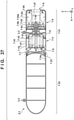
- the seventh embodiment of the present invention will be described below with reference to Figs. 37 to 42 .
- the outline of a flying body including a power supply device 2-1 according to the seventh embodiment is similar to Figs. 5 and 6 described in the second embodiment.
- the housing 2-2 includes a storage portion 7-21 that stores a power generation unit, and a fuel tank 7-22 serving as a reserving portion that stores the fuel of the power generation unit.
- a fuel tank 7-22 serving as a reserving portion that stores the fuel of the power generation unit.
- methanol, gasoline, or the like can be used as the fuel reserved in the fuel tank 7-22.
- the storage portion 7-21 and the fuel tank 7-22 are arrayed along the front-and-rear direction (X direction) of a flying body 2-100 ( Fig. 5 ), and separably connected by a connecting portion 7-23.
- the fuel tank 7-22 is arranged on the front side of the flying body 2-100
- the storage portion 7-21 is arranged on the rear side of the flying body 2-100.
- the storage portion 7-21 and the fuel tank 7-22 are preferably formed into the same thickness (sectional diameter).
- the air drag during forward flight of the flying body 2-100 can be reduced.
- the power generation unit stored in the storage portion 7-21 will be described with reference to Fig. 37 .
- the power generation unit includes a power generator 7-4 and a gas turbine engine 7-5.
- the power generator 7-4 generates power by the output of the gas turbine engine 7-5.
- the power generator 7-4 and the gas turbine engine 7-5 are provided on a common rotating shaft 7-6.
- the power generator 7-4 can generate power.
- the power generator 7-4 and the gas turbine engine 7-5 can be arranged without wasting the space, and the size can be reduced.
- the gas turbine engine 7-5 includes a compressor including an impeller 7-51 and a diffuser 7-52.
- the impeller 7-51 is attached to the rotating shaft 7-6.
- Air taken from air intake ports 7-7 is sent to a compression chamber 7-53 while being compressed via the diffuser 7-52 as the impeller 7-51 rotates.
- the compressed air held in the compression chamber 7-53 is taken from opening portions 7-54a provided in the circumferential wall of a combustion chamber 7-54 and other opening portions into the combustion chamber 7-54.
- fuel injection nozzles 7-55 are provided, and the fuel taken from the fuel tank 7-22 via a pipe 7-8a by a fuel pump 7-8 (supply portion) is injected (supplied) into the combustion chamber 7-54 by the fuel injection nozzles 7-55.
- an ignition device (not shown) ignites the air fuel mixture in the combustion chamber 7-54. After that, combustion of the air fuel mixture continuously occurs in the combustion chamber 7-54.
- the impeller 7-51, the turbine 7-58, and a rotor 7-41 (permanent magnet) of the power generator 7-4 to be described later are provided on the rotating shaft 7-6, and the impeller 7-51 and the rotor 7-41 can integrally be rotated by the rotation of the turbine 7-58.
- the gas turbine engine 7-5 exclusively aims at driving the power generator 7-4, and actively using the exhaust gas flow as the thrust of the flying body 2-100 is not assumed.
- a form in which the exhaust gas flow is used as an auxiliary thrust is also possible.
- the power generator 7-4 includes the rotor 7-41 such as a permanent magnet attached to the rotating shaft 7-6 and a stator 7-42 such as a coil disposed around the rotor 7-41.
- the stator 7-42 can generate power.
- a plurality of fins 7-43 configured to cool the stator 7-42 are provided around the stator 7-42 in the circumferential direction of the rotating shaft 7-6.
- the plurality of fins 7-43 are arranged in a space to which the air taken from the air intake ports 7-7 is guided. When the air passes between the plurality of fins 7-43, the plurality of fins 7-43 are cooled, and the stator 7-42 can thus be cooled.
- a control unit 7-10 includes a circuit that controls power generation of the power generator 7-4, and a circuit that controls driving of the gas turbine engine 7-5.
- An auxiliary power supply such as a battery may be provided as the power supply in activating the control unit 7-10.
- the auxiliary power supply may be provided in the housing 2-2, or may be provided in an airframe 2-101. Power generated by the power generator 7-4 is supplied to a power load (a battery 2-107 or motors 2-105 and 2-106) in the airframe 2-101 via a cable (not shown). The cable may pass through connecting mechanisms 2-3.
- the control unit 7-10 of the power supply device 2-1 may be able to communicate with a control device 2-108 of the airframe 2-101, and the control unit 7-10 may be configured to perform power generation control in accordance with an instruction from the control device 2-108.
- the degree of freedom in designing the airframe 2-101 of the flying body 2-100 can be improved. For example, it is possible to ensure a wider cabin space in the airframe 2-101 and improve the comfort of crew.
- noise and vibrations generated by the operation of the power supply device 2-1 are reduced as compared to a case in which the power supply device 2-1 is provided in the airframe 2-101, and silence can be improved.
- access to the inside of the power supply device 2-1 is easy, the maintenance is facilitated, and the maintenance burden can be reduced.
- the power supply device 2-1 alone can be developed separately from the airframe 2-101, various kinds of qualification tests and type certifications before mass production become easy, and mass production can be implemented early. Furthermore, the power supply device 2-1 has a shape long in the front-and-rear direction of the flying body 2-100, that is, a low air drag shape with a small front projection area. For this reason, even in the arrangement in which the power supply device 2-1 is arranged outside the airframe 2-101, the fuel consumption performance of the flying body 2-100 is not greatly lowered. Since the gas turbine engine 7-5 of the power supply device 2-1 does not aim at generating the thrust of the flying body 2-100, the rigidity of the connecting mechanisms 2-3 can be low, and the structure can be relatively simple.
- a vibration sometimes occurs in the fuel tank 7-22 due to, for example, a vibration transmitted from the airframe 2-101, an airflow outside the airframe 2-101, and the like.
- a so-called sloshing phenomenon occurs in which the liquid fuel reserved in the fuel tank 7-22 causes resonance, and the liquid surface moves up and down (swings). If the sloshing phenomenon occurs, the power supply device 2-1 (housing 2-2) swings to exert an influence on posture control of the airframe 2-101, or the fuel tank 7-22 itself may break.
- the power supply device 2-1 according to this embodiment is configured to be able to suppress the occurrence of the sloshing phenomenon in the fuel tank 7-22.
- Fig. 38 is an X-Z sectional view of the fuel tank 7-22 according to the seventh embodiment.
- the fuel tank 7-22 includes partitions 7-25 that divide the reservation space of fuel into a plurality of partial spaces 7-24 arrayed along the longitudinal direction of the housing 2-2. Since the partitions 7-25 function as wave dissipating plates configured to reduce the swing of the liquid surface of the fuel (liquid) reserved in the fuel tank 7-22, it is possible to suppress the occurrence of the sloshing phenomenon and reduce the influence on posture control of the airframe 2-101 and the breakage of the fuel tank 7-22.
- each of the partitions 7-25a to 7-25d is formed into a plate shape with a plate surface perpendicular to the longitudinal direction of the housing 2-2 and connected to the inner wall of the fuel tank 7-22.
- Vent holes 7-31 that communicate the inside of the fuel tank 7-22 with the outside are provided in the fuel tank 7-22.
- the vent holes 7-31 are provided for several partial spaces divided by the partitions 7-25.
- each of the partial spaces 7-24b to 7-24e is provided with one vent hole 7-31.
- a fuel level sensor 7-32 configured to detect the remaining amount of the fuel is provided in the fuel tank 7-22. Fuel remaining amount information detected by the fuel level sensor 7-32 is transmitted to the control device 2-108 or the control unit 7-10 via a cable.
- Fig. 39 is a view showing one partition 7-25 viewed from the X direction side.
- Opening portions 7-26 configured to make the plurality of partial spaces 7-24a to 7-24e communicate are formed in each of the partitions 7-25a to 7-25d.
- the opening portions 7-26 (an upper opening portion 7-26a and a lower opening portion 7-26b) are formed in each partition 7-25 at two points on the upper and lower sides.
- each of the opening portions 7-26 of the partitions 7-25a to 7-25d is provided with a check valve 7-29 that prevents the reverse flow of the fuel that has passed through the opening portions 7-26.
- the check valve 7-29 is provided on the lower opening portion 7-26b of each of the partitions 7-25a to 7-25d.
- the check valve 7-29 has a function of preventing the fuel that has flowed from the partial space 7-24 on the front side to the partial space 7-24 on the rear side via the lower opening portion 7-26b from reversely flowing to the partial space 7-24 on the front side via the lower opening portion 7-26b.
- the check valve 7-29 can be formed by, for example, a thin plate having an area larger than the opening area of the opening portion 7-26 (lower opening portion 7-26b) and provided on the rear surface of each of the partitions 7-25a to 7-25d to cover the opening portion 7-26 (lower opening portion 7-26b).
- the concave portion 7-22a is provided in the bottom portion on the side of the storage portion 7-21 (power generation unit side) in the fuel tank 7-22.
- a concave portion 7-22b may be provided in the bottom portion in the longitudinal direction of the housing 2-2.
- Fig. 42 is a view showing a modification of the fuel tank 7-22.
- a slope is preferably formed such that the rear side of the flying body 2-100 becomes lower than the front side. This can efficiently collect the fuel remaining in the fuel tank 7-22.
Description
- The present invention relates to a power supply device for a flying body and a flying body.
- An electric propulsion type flying body including an electric driving source such as a motor has been proposed. For example,
U.S. Patent No. 9,248,908 U.S. Patent No. 8,727,271 discloses an electric propulsion type helicopter including a motor that is driven by power of a battery or a gas turbine engine and a power generator. - In an arrangement in which a power supply device such as a battery is disposed in the airframe of a flying body, like
U.S. Patent No. 9,248,908 8,727,271 , to ensure the disposition space, there is a lower degree of freedom in designing another space in the airframe such as a cabin space. -
US2018/002027A1 , Figs 7A-C (to which the search report refers to and on which the preamble ofclaim 1 is based), discloses an aircraft with a propulsion assembly including a nacelle, fuel tanks, an engine, a drive system, a rotor hub, a proprotor and an electronics node. -
US2011/071706A1 discloses an aerial vehicle including a fuel cell hybrid power system. The hybrid power device provides power to portions of a control system residing on an aerial vehicle, a propulsion module, a gimbaled actuator, a laser designator, a video camera, and a flight dynamics and propulsion control module. The power system includes a power board, a power bus, a battery, and a fuel cell module. -
US2017/327219A1 discloses an aircraft including a fuselage, an elongated wing structure, a plurality of nacelles and a plurality of rotors. The aircraft uses a hybrid power system including a first power system and a second power system. The first and second power systems and include a fuel cell, the fuel cell electrochemically combines hydrogen and oxygen to produce electricity, which drives a motor connected to a gearbox, which in turn drives rotor. The fuel cell uses liquid hydrogen stored at least partially in a liquid hydrogen tank within the fuselage. - The present invention provides a power supply device that improves the degree of freedom in designing the airframe of a flying body.
- The present invention in its first aspect provides a power supply device as specified in
claims 1 to 5. - According to the present invention, it is possible to provide a power supply device that improves the degree of freedom in designing the airframe of a flying body.
- Since the power supply device is arranged outside the airframe, the degree of freedom in designing the airframe of the flying body can be improved. The housing has a shape long in the front-and-rear direction of the flying body, and has a low air drag shape with a small front projection area. For this reason, even in the arrangement in which the power supply device is arranged outside the airframe, the fuel consumption performance (air drag reduction) of the flying body is not greatly lowered.
- As the gas turbine engine is employed, the power generation means can be stored in the housing with the cylindrical shape efficiently in terms of space. In addition, when the gas turbine engine of relatively small noise is used, silence can be improved.
- If the flying body comprises an electric propulsion type flying body, and the power load comprises a motor (for example, 105, 106), it is possible to supply sufficient power to a motor serving as a driving source that needs relatively large power and prolong the cruising distance of the flying body.
- If the reserving portion, the power generator, and the gas turbine engine are arranged in this order from the front side in the front-and-rear direction of the flying body, it is possible to efficiently use the internal space of the housing. In particular, the exhaust efficiency can be raised by locating the gas turbine engine at an end, and the exhaust gas flow can be used as an auxiliary thrust.
- If the housing includes, at a rear end portion (for example, 2b) in the front-and-rear direction of the flying body, an exhaust portion (for example, 2b') configured to exhaust a combustion gas of the gas turbine engine to a rear side in the front-and-rear direction of the flying body, it is possible to raise the exhaust efficiency and use the exhaust gas flow as an auxiliary thrust.
- If the reserving portion has a large range in the longitudinal direction of the housing as compared to the storage portion, it is possible to reserve more fuel and prolong the cruising distance of the flying body.
- Further features of the present invention will become apparent from the following description of exemplary embodiments (with reference to the attached drawings).
-
-
Fig. 1 is a schematic view of a flying body including a power supply device according to an embodiment of the present invention; -
Fig. 2 is a perspective view of the power supply device shown inFig. 1 ; -
Fig. 3 shows an explanatory view and a partial enlarged view of the internal structure of the power supply device shown inFig. 1 ; -
Fig. 4 is an explanatory view of a power supply device according to another example, which is not according to the invention and is present for illustration purposes only; -
Fig. 5 is a schematic view of a flying body including a power supply device; -
Fig. 6 is an external view of the power supply device; -
Fig. 7 is a sectional view of the power supply device; -
Fig. 8 is an enlarged view of a region R shown inFig. 7 ; -
Fig. 9 is a schematic view showing an example of attachment of a heat insulating member; -
Fig. 10 is a schematic view showing the sectional structure of the heat insulating member; -
Fig. 11 is a schematic view showing an example in which a second heat insulating member is further provided; -
Fig. 12 is a schematic view of a flying body including a power supply device according to the third embodiment; -
Fig. 13 is a block diagram showing the functional arrangement of the power supply device according to the third embodiment; -
Fig. 14 is a view showing the detailed arrangement of a power generation unit; -
Fig. 15 is a sectional view showing the structure of an air intake portion; -
Fig. 16 is an enlarged sectional view showing the structure of the air intake portion; -
Fig. 17 is a view schematically showing the layout of struts; -
Fig. 18 is a block diagram showing the functional arrangement of a power supply device according to the fourth embodiment; -
Fig. 19 is a view showing the detailed arrangement of a power generation unit PG; -
Fig. 20 is a view showing the sectional structure of air intake portions (INT and INT2); -
Fig. 21 is a view showing a sectional structure concerning a modification of the air intake portion INT; -
Fig. 22 depicts views for exemplarily explaining a driving mechanism configured to drive movable members; -
Fig. 23 is a control block diagram showing control of opening/closing of the movable member in an auxiliary air intake portion; -
Fig. 24 is a control block diagram showing control of air intake and opening/closing of the movable member in the auxiliary air intake portion; -
Fig. 25 is a schematic view showing a state in which part of a housing is cut away by a y-z plane; -
Fig. 26 is a view for explaining the procedure of passage switching control; -
Fig. 27 depicts a view showing the structure of a separation mechanism in a flying body according to the 5Ath embodiment; -
Fig. 28 is a view showing the arrangement of a fixed arm, a separation arm, and a driving arm; -
Fig. 29 depicts a view for explaining an arrangement of a modification of a separation mechanism; -
Fig. 30 depicts a view showing the structure of the separation mechanism of a flying body according to the 5Bth embodiment; -
Fig. 31 depicts a view showing the arrangement of a flying body according to the 5Cth embodiment; -
Fig. 32 depicts external views of a power supply device according to the sixth embodiment; -
Fig. 33 is a sectional view of the power supply device according to the sixth embodiment; -
Fig. 34 is an enlarged view of a region R shown inFig. 33 ; -
Fig. 35 is an external perspective view showing the rear end portion of a fuel tank and a storage portion; -
Fig. 36 is a schematic view showing the storage portion in a state in which the fuel tank is detached viewed from the front side; -
Fig. 37 is a sectional view of a power supply device according to the seventh embodiment; -
Fig. 38 is an X-Z sectional view of a fuel tank; -
Fig. 39 is a view showing one partition viewed from an X direction side; -
Fig. 40 is an X-Y sectional view of the fuel tank; -
Fig. 41 is a view showing a section (Y-Z section) taken along a line A - A inFigs. 38 and40 ; and -
Fig. 42 is a view showing a modification of the fuel tank. - The first to seventh embodiments of the present invention will now be described with reference to the accompanying drawings. The present invention is not limited to the following embodiments, and includes changes and modifications of arrangements within the scope of the present invention. In addition, not all the combinations of features described in the embodiments are necessarily essential to the present invention.
-
Fig. 1 is a schematic view of a flyingbody 100 including apower supply device 1 according to an embodiment of the present invention. InFig. 1 , arrows X, Y, and Z indicate the front-and-rear direction, the widthwise direction (left-and-right direction), and the up-and-down direction of the flyingbody 100, respectively. The flyingbody 100 according to this embodiment is an electric propulsion type flyingbody using motors - The flying
body 100 includes anairframe 101, amain rotor 102 provided in the upper portion of theairframe 101, atail rotor 103 provided in the rear portion of theairframe 101, and skids 104. Themotor 105 is a driving source that rotates themain rotor 102, and themotor 106 is a driving source that rotates thetail rotor 103. Driving of themotors control device 107 using power supplied from thepower supply device 1. - The
power supply device 1 functions as the main power supply of the flyingbody 100, and supplies not only the driving power for themotors body 100. Thepower supply device 1 will be described with reference toFig. 2 in addition toFig. 1 .Fig. 2 is a perspective view of thepower supply device 1. - The
power supply device 1 includes ahousing 2 that forms the outer wall of thehousing 2, and a plurality of connectingportions 3 that connect thehousing 2 and theairframe 101. Thehousing 2 is arranged outside theairframe 101 and, in this embodiment, supported at the center in the Y direction while being hung from the bottom wall of theairframe 101 via the connectingportions 3. When thehousing 2 is arranged outside theairframe 101, occupation of the internal space of theairframe 101 by thepower supply device 1 can be avoided. This contributes to expansion of a cabin, improvement of layout of other components, and improvement of maintenability of thepower supply device 1. - The
housing 2 has an outer shape long in the X direction. In this embodiment, thehousing 2 has a pod-like outer shape long in the X direction in particular. In other words, the X direction is the longitudinal direction of thehousing 2. When thehousing 2 has such an outer shape, the air drag during forward flight of the flyingbody 100 can be reduced while arranging thehousing 2 outside theairframe 101. Thehousing 2 according to this embodiment is a hollow body having a cylindrical shape long in the X direction. This can make the influence of a cross wind smaller. Thehousing 2 can be formed by, for example, connecting a plurality of parts having a cylindrical shape in the X direction. InFig. 2 , a center axis C indicates the center axis of the cylinder. - Of a
distal end portion 2a and arear end portion 2b of thehousing 2 in the X direction, thedistal end portion 2a has a tapered shape whose diameter is reduced toward the front. In this embodiment, thedistal end portion 2a has a hemispherical shape but may have a triangular pyramid shape. When thedistal end portion 2a has a tapered shape, the air drag during forward flight of the flyingbody 100 can further be reduced. A plurality ofair intake ports 2c configured to take air into apower generation unit 4 to be described later are formed in thehousing 2. Theair intake port 2c is a slit-shaped opening long in the X direction, and the plurality ofair intake ports 2c are formed in the circumferential direction of thehousing 2. - The plurality of (here, two) connecting
portions 3 are formed apart in the X direction. Thehousing 2 is connected apart from theairframe 101 by the connectingportions 3. The connectingportion 3 may inseparably fix thepower supply device 1 and theairframe 101 by welding or the like, but may detachably connect thepower supply device 1 and theairframe 101. The structure that detachably connect them may be a fastening structure using a bolt and a threaded hole, or may be an engaging structure using a hook and a hole. When thepower supply device 1 is detachable from theairframe 101, a contribution can be made for exchange of thepower supply device 1 or improvement of maintenability. - The internal structure of the
housing 2 will be described next with reference toFig. 3. Fig. 3 shows an explanatory view and a partial enlarged view of the internal structure of the power supply device, which correspond to a sectional view of thepower supply device 1 passing through the center axis C. - The internal space of the
housing 2 is roughly divided into a reservingportion 2d on the front side and astorage portion 2e on the rear side. The reservingportion 2d and thestorage portion 2e are arranged in the longitudinal direction (X direction) of thehousing 2. With this layout, thepower supply device 1 that has a small air drag and is long in the X direction can easily be formed. A plurality of annular reinforcingmembers 2f are provided apart in the X direction on the inner circumferential surface of thehousing 2, thereby improving the strength of thehousing 2. - The
storage portion 2e stores thepower generation unit 4. The reservingportion 2d is a space to reserve the fuel (light oil or the like) of thepower generation unit 4. In this embodiment, afuel tank 7 is stored. However, the reservingportion 2d itself may form a fuel tank. Thefuel tank 7 is a hollow body having a tubular shape long in the X direction. The reserved fuel is supplied to thepower generation unit 4 by a pump (not shown). In this embodiment, the reservingportion 2d is designed to have a large range in the X direction of thehousing 2 as compared to thestorage portion 2e, and a larger amount of fuel can be reserved. This can increase the cruising distance of the flyingbody 100. - In this embodiment, the reserving
portion 2d is also used as the storage space for acontrol unit 8. Thecontrol unit 8 controls thepower generation unit 4. In this embodiment, thecontrol unit 8 is provided in thepower supply device 1. However, instead of providing thecontrol unit 8 in thepower supply device 1, thecontrol unit 107 of the flyingbody 100 may control thepower generation unit 4. - The
power generation unit 4 includes apower generator 5, and agas turbine engine 6. Thepower generator 5 generates power by the output of thegas turbine engine 6. Thegas turbine engine 6 includes arotating shaft 60 provided on the same axis as the rotation axis C of thehousing 2. When therotating shaft 60 is provided on the same axis as the rotation axis C, the largergas turbine engine 6 can be stored in thehousing 2 having a cylindrical shape without wasting the space. - The
gas turbine engine 6 includes acompressor 61. Thecompressor 61 includes animpeller 61a attached to therotating shaft 60, and adiffuser 61b. As theimpeller 61a rotates, air is sent from theair intake ports 2c to acompression chamber 62 while being compressed via thediffuser 61b. - The compressed air in the
compression chamber 62 flows from openingportions 63a provided in the circumferential wall of acombustion chamber 63 and other opening portions (not shown) into thecombustion chamber 63. In thecombustion chamber 63, a plurality offuel injection nozzles 64 are provided in the circumferential direction of the rotation axis C. The fuel reserved in thefuel tank 7 is supplied to thefuel injection nozzles 64 via a pipe (not shown), and thefuel injection nozzles 64 inject the fuel into thecombustion chamber 63. At the time of start, an ignition device (not shown) ignites the air fuel mixture in thecombustion chamber 63. After that, combustion of the air fuel mixture continuously occurs in thecombustion chamber 63. - A combustion gas flow that has a high temperature and a high pressure in the
combustion chamber 63 jets out fromturbine nozzles 65 to atubular exhaust pipe 67 on the same axis as the center axis C and, in the process, rotates aturbine 66 attached to therotating shaft 60. Theturbine 66, the rotatingshaft 60, and theimpeller 61a integrally rotate. Anexhaust portion 2b' that is an opening portion communicating with theexhaust pipe 67 is formed in therear end portion 2b of thehousing 2, and the combustion gas flow (exhaust gas flow) is discharged to the rear of thehousing 2. In this embodiment, since thegas turbine engine 6 is arranged adjacent to therear end portion 2b of thehousing 2, exhaust to the rear can smoothly be performed. Note that in this embodiment, thegas turbine engine 6 exclusively aims at driving thepower generator 5, and actively using the exhaust gas flow as the thrust of the flyingbody 100 is not assumed. However, a form in which the exhaust gas flow is used as an auxiliary thrust can also be employed. - The
power generator 5 includes arotating shaft 50 on the same axis as the rotatingshaft 60. That is, the rotatingshaft 50 is also provided on the same axis as the center axis C, and thelarger power generator 5 can be stored in thehousing 2 having a cylindrical shape without wasting the space. In this embodiment, the rotatingshaft 50 and therotating shaft 60 are integrally formed.Bearings 50a that rotatably support the rotating shaft 50 (and the rotating shaft 60) are provided at the two end portions of thepower generator 5 in the X direction. - A
rotor 51 such as a permanent magnet is provided on therotating shaft 50, and astator 52 such as a coil is provided around therotor 51. A plurality offins 53 for cooling are provided around thestator 52 in the circumferential direction of therotating shaft 50 and cool thepower generator 5 by air cooling. - The
control unit 8 includes a circuit that controls power generation of thepower generator 5, and a circuit that controls driving of thegas turbine engine 6. An auxiliary power supply such as a lead battery may be provided as the power supply in activating thecontrol unit 8. The auxiliary power supply may be provided in thepower supply device 1, or an auxiliary power supply provided on the side of theairframe 101 may be used. Power generated by thepower generator 5 is supplied to thecontrol unit 107 of the flyingbody 100 via a cable (not shown). The cable may pass through the connectingportions 3. Thecontrol unit 8 and thecontrol unit 107 may be able to communicate with each other, and thecontrol unit 8 may perform power generation control in accordance with an instruction from thecontrol unit 107. - In the
power supply device 1 with this arrangement, thegas turbine engine 6 is driven by the fuel reserved in thefuel tank 7, the rotatingshaft 50 is rotated by the rotation of therotating shaft 60 that is the output of thegas turbine engine 6, and thepower generator 5 generates power. The generated power is supplied to the flyingbody 100 and used to drive themotors - Since the
power supply device 1 is arranged outside theairframe 101, the degree of freedom in designing theairframe 101 of the flyingbody 100 can be improved. For example, it is possible to ensure a wider cabin space in theairframe 101 and improve the comfort of crew. In addition, noise and vibrations generated by the operation of thepower supply device 1 are reduced as compared to a case in which thepower supply device 1 is provided in theairframe 101, and silence improves. Furthermore, as compared to a case in which thepower supply device 1 is provided in theairframe 101, access to the inside of thepower supply device 1 is easy, the maintenance is facilitated, and the maintenance burden is reduced. Thepower supply device 1 alone can be developed separately from theairframe 101, various kinds of qualification tests and type certifications before mass production become easy, and mass production can be implemented early. Thehousing 2 of thepower supply device 1 has a shape long in the front-and-rear direction of the flyingbody 100, and forms a pod in a low air drag shape with a small front projection area. For this reason, even in the arrangement in which thepower supply device 1 is arranged outside theairframe 101, the fuel consumption performance (air drag reduction) of the flyingbody 100 is not greatly lowered. Since thegas turbine engine 6 of thepower supply device 1 does not aim at generating the thrust of the flyingbody 100, the rigidity of the connectingportions 3 can be low, and the structure can be relatively simple. - In the above embodiment, the combination of the
gas turbine engine 6 and thepower generator 5 is shown as thepower generation unit 4. However, the present invention is not limited to this.Fig. 4 shows other examples EX1 to EX3 of thepower generation unit 4 which are not according to the invention and are present for illustration purposes only. - The example EX1 shows an example (not covered by the enclosed claims) in which a fuel cell is used. The
power generation unit 4 includes afuel reformer 41, a fuel cell (fuel cell stack) 42, and aninverter 43. Methanol, gasoline, or the like is reserved in thefuel tank 7. Thefuel reformer 41 reforms the fuel in thefuel tank 7 into hydrogen gas by a chemical reaction, and supplies it to thefuel cell 42. Thefuel cell 42 generates power using the hydrogen gas supplied from thefuel reformer 41 and air (oxygen) taken from theair intake ports 2c. The exhaust gas is exhausted from theexhaust portion 2b' to the outside of thehousing 2. The generated power is rectified by theinverter 43 and supplied to theairframe 101. In thehousing 2, a control unit that controls the power generation amount of thepower generation unit 4 may be provided. In the example using the fuel cell, it is advantageous from the viewpoint of the power generation efficiency or low pollution. In addition, pipes can be made simpler than in the example in which thegas turbine engine 6 and thepower generator 5 are combined. - The example EX2 also shows an example in which a fuel cell is used. In this example, it is assumed that hydrogen is reserved in the
fuel tank 7. Thepower generation unit 4 does not include thefuel reformer 41, and includes the fuel cell (fuel cell stack) 42 and theinverter 43. Hydrogen gas is directly supplied from thefuel tank 7 to thefuel cell 42. Since thefuel reformer 41 is not provided, the apparatus can be made compact and lightweight. - The
power generation unit 4 can also be formed by combining an internal combustion engine other than a gas turbine engine and a power generator. The example EX3 shows an example (not covered by the enclosed claims). Thepower generation unit 4 includes areciprocating engine 44, adecelerator 45, and apower generator 46. Thereciprocating engine 44 is, for example, a gasoline engine or a diesel engine, and a fuel such as gasoline or light oil is reserved in thefuel tank 7 in accordance with the type of thereciprocating engine 44. - The
reciprocating engine 44 can be either a single-cylinder engine or a multi-cylinder engine. In a case of a multi-cylinder engine, various kinds of engine layouts such as an in-line layout or a V layout can be employed as the cylinder layout. In this embodiment, thereciprocating engine 44 is arranged such that its cylinder line direction is directed in the X direction. Because of this engine layout, it is difficult to arrange anoutput shaft 44a (crankshaft) on the same axis as the center axis C in many cases. In this embodiment, the position of the shaft is converted by interposing theshaft conversion portion 45 between thereciprocating engine 44 and thepower generator 46. Theshaft conversion portion 45 is, for example, a decelerator such as a gear device. Aninput shaft 45a of theshaft conversion portion 45 is arranged on the same axis as theoutput shaft 44a, and anoutput shaft 45b of theshaft conversion portion 45 is arranged on the same axis as the center axis C. Thepower generator 46 is a power generator having a structure similar to that of thepower generator 5. Thepower generator 46 includes a rotating shaft on the same axis as theoutput shaft 45b, and generates power as it rotates. When thereciprocating engine 44 is used, thepower supply device 1 of relatively low cost can be provided. - In the above embodiment, a helicopter has been shown as the flying body. In addition to such a rotorcraft, the present invention can be applied not only to an aircraft such as a fixed-wing aircraft or airship but also to a flying type personal mobility, spacecraft, a space shuttle, and the like. The rotorcraft can include a glider aircraft represented by a glider and an aircraft represented by a propeller plane. The present invention is also applicable to a flying body that is not of electric propulsion type.
- The connection portions of the power supply device can include the upper surface of a wing portion of the airframe and the bottom surface of a wing portion of the airframe in addition to the bottom surface of the airframe. The power supplied by the power supply device may be power supplied to a power load that constitutes a driving source such as a motor, may be power supplied to a power load other than the driving source, or may be power supplied to both.
- A plurality of power supply devices may be provided in one flying body. If a plurality of power supply devices are provided, they may be juxtaposed in the widthwise direction of the flying body, or may be arranged in one line in the front-and-rear direction of the flying body.
- In the above embodiment, an example in which the
housing 2 has a cylindrical shape has been described. However, thehousing 2 may have another tubular shape such as a square tubular shape. In addition, thehousing 2 may include a portion with a cylindrical shape and a portion with a square tubular shape. - The second embodiment of the present invention will be described with reference to
Figs. 5 to 11 . -
Fig. 5 is a schematic view of a flying body 2-100 including a power supply device 2-1 according to the second embodiment of the present invention. InFig. 5 , arrows X, Y, and Z indicate the front-and-rear direction, the widthwise direction (left-and-right direction), and the up-and-down direction of the flying body 2-100, respectively. The flying body 2-100 according to the second embodiment is an electric propulsion type flying body using motors 2-105 and 2-106 as driving sources and, more particularly, a helicopter. - The flying body 2-100 includes an airframe 2-101 with a cabin, a main rotor 2-102 provided in the upper portion of the airframe 2-101, a tail rotor 2-103 provided in the rear portion of the airframe 2-101, and skids 2-104. The motor 2-105 is a driving source that rotates the main rotor 2-102, and the motor 2-106 is a driving source that rotates the tail rotor 2-103. Power is suppled from a battery 2-107 to the motors 2-105 and 2-106, and driving of the motors 2-105 and 2-106 is controlled by a control device 2-108. In addition, power generated by the power supply device 2-1 is supplied to the battery 2-107 via a cable (not shown). In the second embodiment, the power generated by the power supply device 2-1 is supplied to the battery 2-107 of the airframe 2-101. However, the power generated by the power supply device 2-1 may directly be supplied to the motors 2-105 and 2-106 without an intervention of a battery.
- The power supply device 2-1 is arranged outside the airframe 2-101, and connected to the airframe 2-101 by a plurality of connecting mechanisms 2-3. In the second embodiment, the power supply device 2-1 is arranged between the left and right skids 2-104 in the Y direction, and supported while being hung from the bottom wall of the airframe 2-101. When the power supply device 2-1 is arranged outside the airframe 2-101, occupation of the internal space of the airframe 2-101 by the power supply device 2-1 can be avoided. This can expand the cabin, improve layout of other components, and improve of maintenability of the power supply device 2-1.
- The power supply device 2-1 will be described next with reference to
Figs. 6 and7 .Fig. 6 is an external view of the power supply device 2-1, andFig. 7 is a sectional view of the power supply device 2-1. The power supply device 2-1 includes a hollow housing 2-2 that forms the outer wall of the power supply device 2-1, and the plurality of connecting mechanisms 2-3 that connect the housing 2-2 and the airframe 2-101. - The housing 2-2 has an outer shape long in the X direction (that is, a pod-like outer shape long in the X direction). Hence, in other words, the X direction defined in the second embodiment can be said to be the longitudinal direction of the housing 2-2. When the housing 2-2 arranged outside the airframe 2-101 has such an outer shape, the air drag during forward flight of the flying body 2-100 can be reduced. Since the body portion of the housing 2-2 according to the second embodiment has a columnar shape, the influence of a cross wind can be made smaller. In addition, the distal end portion of the housing 2-2 has a tapered shape whose diameter is reduced toward the front. In the second embodiment, the distal end portion of the housing 2-2 is formed into a hemispherical shape but may have a triangular pyramid shape. When the distal end portion is formed into a tapered shape, the air drag during forward flight of the flying body 2-100 can further be reduced.
- The plurality of connecting mechanisms 2-3 are provided on the housing 2-2 apart in the front-and-rear direction of the flying body 2-100, and connect the housing 2-2 and the airframe 2-101. The housing 2-2 according to the second embodiment includes a total of two connecting mechanisms 2-3 including one connecting mechanism 2-3 on a storage portion 2-21 to be described later, and one connecting mechanism 2-3 on a fuel tank 2-22, and is connected apart from the airframe 2-101 by the plurality of (two) connecting mechanisms 2-3. The connecting mechanism 2-3 detachably connects the power supply device 2-1 (housing 2-2) and the airframe 2-101. The structure may be a fastening structure using a bolt and a threaded hole, or may be an engaging structure using a hook and a hole. When the power supply device 2-1 (housing 2-2) is detachable from the airframe 2-101, exchange of the power supply device 2-1 can be facilitated, or maintenability can be improved.
- The internal structure of the housing 2-2 will be described next. The housing according to the second embodiment includes the storage portion 2-21 that stores a power generation unit, and the fuel tank 2-22 serving as a reserving portion that stores the fuel of the power generation unit. For example, methanol, gasoline, or the like can be used as the fuel reserved in the fuel tank 2-22. The storage portion 2-21 and the fuel tank 2-22 are arrayed along the front-and-rear direction (X direction) of the flying body 2-100, and separably connected by a connecting portion. In the second embodiment, the fuel tank 2-22 is arranged on the front side of the flying body 2-100, and the storage portion 2-21 is arranged on the rear side of the flying body 2-100. In addition, the storage portion 2-21 and the fuel tank 2-22 are preferably formed into the same thickness (sectional diameter). When the storage portion 2-21 and the fuel tank 2-22 are constituted/arranged in this way, the air drag during forward flight of the flying body 2-100 can be reduced.
- The power generation unit stored in the storage portion 2-21 will be described with reference to
Figs. 7 and8. Fig. 8 is an enlarged view of a region R shown inFig. 7 . The power generation unit includes a power generator 2-4 and a gas turbine engine 2-5. The power generator 2-4 generates power by the output of the gas turbine engine 2-5. In the second embodiment, the power generator 2-4 and the gas turbine engine 2-5 are provided on a common rotating shaft 2-6. When the gas turbine engine 2-5 rotationally drives the rotating shaft 2-6, the power generator 2-4 can generate power. With this arrangement, the power generator 2-4 and the gas turbine engine 2-5 can be arranged without wasting the space, and the size can be reduced. - The gas turbine engine 2-5 includes a compressor including an impeller 2-51 and a diffuser 2-52. The impeller 2-51 is attached to the rotating shaft 2-6. Air taken from air intake ports 2-7 is sent to a compression chamber 2-53 while being compressed via the diffuser 2-52 as the impeller 2-51 rotates. As shown in
Fig. 8 , the compression chamber 2-53 is a closed space defined between a tubular outer circumferential case 2-21a that constitutes part (first portion) of the storage portion 2-21 surrounding the gas turbine engine 2-5 and a tubular inner circumferential case 2-21b that is arranged inside the outer circumferential case 2-21a and constitutes an exhaust pipe 2-57. The compressed air held in the compression chamber 2-53 is taken from opening portions 2-54a provided in the circumferential wall of a combustion chamber 2-54 and other opening portions into the combustion chamber 2-54. In the combustion chamber 2-54, fuel injection nozzles 2-55 are provided, and the fuel taken from the fuel tank 2-22 via a pipe by a fuel pump 2-8 (supply portion) is injected (supplied) into the combustion chamber 2-54 by the fuel injection nozzles 2-55. At the time of start, an ignition device (not shown) ignites the air fuel mixture in the combustion chamber 2-54. After that, combustion of the air fuel mixture continuously occurs in the combustion chamber 2-54. - A combustion gas that has a high temperature and a high pressure in the combustion chamber 2-54 jets out from turbine nozzles 2-56 to the exhaust pipe 2-57 (the inside of the inner circumferential case 2-21b), rotates a turbine 2-58 attached to the rotating shaft 2-6, and is discharged to the rear from an exhaust port 2-9 provided in the rear portion of the power supply device 2-1. The impeller 2-51, the turbine 2-58, and a rotor 2-41 (permanent magnet) of the power generator 2-4 to be described later are provided on the rotating shaft 2-6, and the impeller 2-51 and the rotor 2-41 can integrally be rotated by the rotation of the turbine 2-58. Note that in the second embodiment, the gas turbine engine 2-5 exclusively aims at driving the power generator 2-4, and actively using the exhaust gas flow as the thrust of the flying body 2-100 is not assumed. However, a form in which the exhaust gas flow is used as an auxiliary thrust is also possible.
- The power generator 2-4 includes the rotor 2-41 such as a permanent magnet attached to the rotating shaft 2-6 and a stator 2-42 such as a coil disposed around the rotor 2-41. When the rotating shaft 2-6 is rotated by the gas turbine engine 2-5, and the rotor 2-41 attached to the rotating shaft 2-6 thus rotates, the stator 2-42 can generate power. In addition, a plurality of fins 2-43 configured to cool the stator 2-42 are provided around the stator 2-42 in the circumferential direction of the rotating shaft 2-6. The plurality of fins 2-43 are arranged in a space to which the air taken from the air intake ports 2-7 is guided. When the air passes between the plurality of fins 2-43, the plurality of fins 2-43 are cooled, and the stator 2-42 can thus be cooled.
- A control unit 2-10 includes a circuit that controls power generation of the power generator 2-4, and a circuit that controls driving of the gas turbine engine 2-5. An auxiliary power supply such as a battery may be provided as the power supply in activating the control unit 2-10. The auxiliary power supply may be provided in the housing 2-2, or may be provided in the airframe 2-101. Power generated by the power generator 2-4 is supplied to a power load (the battery 2-107 or the motors 2-105 and 2-106) in the airframe 2-101 via a cable (not shown). The cable may pass through the connecting mechanisms 2-3. In addition, the control unit 2-10 of the power supply device 2-1 may be able to communicate with the control device 2-108 of the airframe 2-101, and the control unit 2-10 may be configured to perform power generation control in accordance with an instruction from the control device 2-108.
- As described above, when the power supply device 2-1 is arranged outside the airframe 2-101, the degree of freedom in designing the airframe 2-101 of the flying body 2-100 can be improved. For example, it is possible to ensure a wider cabin space in the airframe 2-101 and improve the comfort of crew. In addition, noise and vibrations generated by the operation of the power supply device 2-1 are reduced as compared to a case in which the power supply device 2-1 is provided in the airframe 2-101, and silence can be improved. Furthermore, as compared to a case in which the power supply device 2-1 is provided in the airframe 2-101, access to the inside of the power supply device 2-1 is easy, the maintenance is facilitated, and the maintenance burden can be reduced. The power supply device 2-1 alone can be developed separately from the airframe 2-101, various kinds of qualification tests and type certifications before mass production become easy, and mass production can be implemented early. Furthermore, the power supply device 2-1 has a shape long in the front-and-rear direction of the flying body 2-100, that is, a low air drag shape with a small front projection area. For this reason, even in the arrangement in which the power supply device 2-1 is arranged outside the airframe 2-101, the fuel consumption performance of the flying body 2-100 is not greatly lowered. Since the gas turbine engine 2-5 of the power supply device 2-1 does not aim at generating the thrust of the flying body 2-100, the rigidity of the connecting mechanisms 2-3 can be low, and the structure can be relatively simple.
- The power supply device 2-1 according to the second embodiment is arranged outside the airframe 2-101. Since the gas turbine engine 2-5 that is a constituent element of the power generation unit becomes hot, safety needs to be ensured. In addition, since the power supply device 2-1 is exposed to outside air at the time of flight, there is a fear about lowering of the thermal efficiency (fuel consumption performance) of the gas turbine engine 2-5. Hence, in the power supply device 2-1 according to the second embodiment, in the housing 2-2, the outer circumferential case 2-21a that is part (first portion) of the storage portion 2-21 surrounding the gas turbine engine 2-5 is covered by a heat insulating member 2-23.
- An example of the arrangement of the heat insulating member 2-23 will be described with reference to
Fig. 8 . The heat insulating member 2-23 is formed into a tubular shape to cover the tubular outer circumferential case 2-21a. In the portion where the exhaust port 2-9 is arranged, an opening is provided so the discharge of the combustion gas is not impeded. In addition, the sectional diameter (thickness) of the heat insulating member 2-23 is formed to be equal to or less than the sectional diameter (thickness) of part (second portion 2-21c) of the storage portion 2-21 surrounding the power generator 2-4. More preferably, the outer surface of the heat insulating member 2-23 is configured to form a continuous surface that continues to the outer surface of the second portion 2-21c. That is, the heat insulating member 2-23 is preferably configured not to form a step at the boundary between the outer surface of the second portion 2-21c of the storage portion 2-21 and the outer surface of the heat insulating member 2-23 (for example, to form a step of 0.5 mm or less). When the heat insulating member 2-23 has such an outer shape, the air drag during forward flight of the flying body 2-100 can be reduced. - In the second embodiment, as shown in
Fig. 9 , the heat insulating member 2-23 is formed into a tubular shape, fitted on the outer circumferential case 2-21a, and joined to the outer circumferential case 2-21a. As the joining method for the heat insulating member 2-23 and the outer circumferential case 2-21a, for example, adhesive joining using an adhesive, mechanical joining using a rivet, a screw, or the like, or welding can be used. If mechanical joining using a detachable part such as a screw is applied, the heat insulating member 2-23 may be configured to be detachable for the outer circumferential case 2-21a. In a case in which the heat insulating member 2-23 is configured to be detachable, when performing maintenance of the gas turbine engine 2-5, the heat insulating member 2-23 can be detached from the outer circumferential case 2-21a to easily access the gas turbine engine 2-5. Hence, the maintenability can be improved. - The detailed sectional structure of the heat insulating member 2-23 will be described next with reference to
Fig. 10. Fig. 10 is a schematic view showing the sectional structure of the heat insulating member 2-23. The heat insulating member 2-23 includes an inside member 2-23a that surrounds the outer circumferential case 2-21a (the first portion of the storage portion 2-21), an outside member 2-23b that surrounds the inside member 2-23a, and a core member 2-23c interposed between the inside member 2-23a and the outside member 2-23b. The inside member 2-23a is in contact with (connected to) the outer surface of the outer circumferential case 2-21a. In the second embodiment, the inside member 2-23a and the outside member 2-23b are made of a metal such as stainless steel or steel, and the core member 2-23c is made of at least one of alumina fiber, glass fiber, and ceramic fiber. When the core member 2-23c is interposed in this way, a higher heat insulating effect can be implemented as compared to a case in which the gas turbine engine 2-5 is covered with only a metal such as stainless steel or steel. It is therefore possible to ensure safety and reduce the lowering of the thermal efficiency (fuel consumption performance) of the gas turbine engine 2-5. - Here, in the second embodiment, a heat insulating member 2-24 (second heat insulating member) may also be provided between the power generator 2-4 and the gas turbine engine 2-5. For example, as shown in
Fig. 11 , the heat insulating member 2-24 can be provided on the surface of the diffuser 2-52 of the gas turbine engine 2-5 on the side of the power generator 2-4.Fig. 11 is an enlarged view of the region R inFig. 7 , and shows an example in which the heat insulating member 2-24 is provided between the power generator 2-4 and the gas turbine engine 2-5, in addition to the heat insulating member 2-23 surrounding the outer circumferential case 2-21a. When the heat insulating member 2-24 is provided in this way, heat transmitted from the gas turbine engine 2-5 to the power generator 2-4 can be reduced, and the lowering of the thermal efficiency (fuel consumption performance) of the gas turbine engine 2-5 can further be reduced. In the power generator 2-4 as well, the lowering of the power generation efficiency caused by heat can be reduced. - In the above second embodiment, a helicopter has been shown as the flying body 2-100. In addition to such a rotorcraft, the present invention can be applied not only to an aircraft such as a fixed-wing aircraft or airship but also to a flying type personal mobility, spacecraft, a space shuttle, and the like. The rotorcraft can include a glider aircraft represented by a glider and an aircraft represented by a propeller plane. The present invention is also applicable to a flying body that is not of electric propulsion type.
- The connection portions of the power supply device 2-1 can include the upper surface of a wing portion of the airframe 2-101 and the bottom surface of a wing portion of the airframe 2-101 in addition to the bottom surface of the airframe 2-101. The power supplied by the power supply device 2-1 may be power supplied to a power load that constitutes a driving source such as a motor, may be power supplied to a power load other than the driving source, or may be power supplied to both.
- A plurality of power supply devices 2-1 may be provided in one flying body. If a plurality of power supply devices are provided, they may be juxtaposed in the widthwise direction of the flying body, or may be arranged in one line in the front-and-rear direction of the flying body.
- In the above second embodiment, an example in which the housing 2-2 has a cylindrical shape has been described. However, the housing 2-2 may have another tubular shape such as a square tubular shape. In addition, the housing 2-2 may include a portion with a cylindrical shape and a portion with a square tubular shape.
- The third embodiment of the present invention will be described below with reference to
Figs. 12 to 17 . -
Fig. 12 is a schematic view of a flying body 3-10 including a power supply device 3-100 according to the third embodiment of the present invention. InFig. 12 , arrows x, y, and z indicate the front-and-rear direction, the widthwise direction (left-and-right direction), and the up-and-down direction of the flying body 3-10, respectively. The flying body 3-10 according to the third embodiment is an electric propulsion type flying body using motors 3-305 and 3-306 as driving sources and, more particularly, a helicopter. - The flying body 3-10 includes an airframe 3-200, a main rotor 3-202 provided in the upper portion of the airframe 3-200, a tail rotor 3-203 provided in the rear portion of the airframe 3-200, and skids 3-204. The motor 3-305 is a driving source that rotates the main rotor 3-202, and the motor 3-306 is a driving source that rotates the tail rotor 3-203. Driving of the motors 3-305 and 3-306 is controlled by a control unit 3-207 (control device) using power supplied from the power supply device 3-100.
- The power supply device 3-100 functions as the main power supply of the flying body 3-10, and supplies not only the driving power for the motors 3-305 and 3-306 but also power to each power load in the flying body 3-10.
- The power supply device 3-100 includes a housing HS that forms the outer wall of the power supply device 3-100, and a plurality of connecting portions (to be referred to as "separation mechanisms SP" hereinafter) configured to be able to connect or separate the housing HS to or from the airframe 3-200. A plurality of (here, two) separation mechanisms SP are provided apart in the x direction. The housing HS is connected apart from the airframe 3-200 by the separation mechanisms SP. The housing HS is arranged outside the airframe 3-200 and, in the third embodiment, supported at the center in the y direction while being hung from the bottom wall of the airframe 3-200 via the separation mechanisms SP. When the housing HS is arranged outside the airframe 3-200, occupation of the internal space of the airframe 3-200 by the power supply device 3-100 can be avoided. This contributes to expansion of a cabin, improvement of layout of other components, and improvement of maintenability of the power supply device 3-100.
- The housing HS has an outer shape long in the x direction. In the third embodiment, the housing HS has a pod-like outer shape long in the x direction in particular. In other words, the x direction is the longitudinal direction of the housing HS. When the housing HS has such an outer shape, the air drag during forward flight of the flying body 3-10 can be reduced while arranging the housing HS outside the airframe 3-200. The housing HS according to the third embodiment is a hollow body having a cylindrical shape long in the x direction. This can make the influence of a cross wind smaller.
- The housing HS can be formed by, for example, connecting a plurality of parts having a cylindrical shape in the x direction. Of a distal end portion 3-100a and a rear end portion 3-100b of the housing HS in the x direction, the distal end portion 3-100a has a tapered shape whose diameter is reduced toward the front. In the third embodiment, the distal end portion 3-100a has a hemispherical shape but may have a triangular pyramid shape. When the distal end portion 3-100a has a tapered shape, the air drag during forward flight of the flying body 3-10 can further be reduced.
-
Fig. 13 is a block diagram showing the functional arrangement of the power supply device 3-100 according to the third embodiment of the present invention. The flying body 3-10 including a propulsion device 3-300 that generates a thrust based on power includes the power supply device 3-100 and the airframe 3-200 (airframe main body). The power supply device 3-100 is connected to the outside of the airframe 3-200. Here, the propulsion device 3-300 includes the main rotor 3-202 using the motor 3-305 as the driving source, and the tail rotor 3-203 using the motor 3-306 as the driving source, which have been described with reference toFig. 12 . The power supply device 3-100 supplies generated power to the control unit 3-207 of the airframe 3-200, and the control unit 3-207 controls driving of the motors 3-305 and 3-306 based on the supplied power. InFig. 13 , the x direction is the flying direction in which the flying body 3-10 propels, and is the longitudinal direction of the power supply device 3-100. The y direction is the widthwise direction of the housing HS, and the z direction is the vertical direction of the housing HS orthogonal to the longitudinal direction (x direction) and the widthwise direction (y direction) of the housing HS. - A power generation portion PG includes a power generator GE and a driving portion DR (gas turbine engine), and the power generator GE generates power by the output of the driving portion DR. Here, the driving portion DR (gas turbine engine) includes a compressor COM, a combustion device BST, and a turbine TB, and generates motive power used to rotationally drive the power generator GE.
- The power generation portion PG (the power generator GE, the compressor COM, the combustion device BST, and the turbine TB) supplies power used to drive the propulsion device 3-300 (the main rotor 3-202, the tail rotor 3-203, and the motors 3-305 and 3-306) of the flying body 3-10 that generates a thrust.
- In the power supply device 3-100, the hollow cylindrical housing HS that stores the power generation portion PG (the power generator GE, the compressor COM, the combustion device BST, and the turbine TB), a reserving portion TN(fuel tank) that reserves a fuel and supplies it to the combustion device BST in the power generation portion PG, and an air intake portion INT that takes outside air and supplies it to the compressor COM in the power generation portion PG is connected to the airframe 3-200 of the flying body 3-10 via the detachable separation mechanisms SP.
- As shown in
Fig. 13 , in the housing HS of the power supply device 3-100, the reserving portion TN (fuel tank), the air intake portion INT, and the power generation portion PG (the power generator GE and the driving portion DR (the gas turbine engine: the compressor COM, the combustion device BST, and the turbine TB)) are integrally packaged. The power supply device 3-100 is connected in the vertical direction to the lower side surface of the airframe 3-200 via the separation mechanisms SP. - An inlet portion 3-110 of the air intake portion INT is formed in the outer peripheral surface of the housing HS, and takes the air outside the housing HS. The air taken by the inlet portion 3-110 of the air intake portion INT is introduced into the compressor COM via an introduction passage formed in the housing. The air intake portion INT will be described later in detail with reference to
Figs. 15 and16 . -
Fig. 14 is a view showing the detailed arrangement of the power generation portion PG (the power generator GE and the driving portion DR (gas turbine engine)), and this portion is an arrangement corresponding to a portion A inFig. 15 . The driving portion DR (gas turbine engine) includes a rotating shaft 3-60 provided on the same axis as a rotation axis C of the housing HS. When the rotating shaft 3-60 is provided on the same axis as the rotation axis C, the larger driving portion DR (gas turbine engine) can be stored in the housing HS having a cylindrical shape without wasting the space. - The compressor COM of the driving portion DR (gas turbine engine) includes an impeller 3-61a attached to the rotating shaft 3-60, and a diffuser 3-61b. As the impeller 3-61a rotates, air taken from the air intake portion INT is sent to a compression chamber 3-62 while being compressed via the diffuser 3-61b.
- The compressed air in the compression chamber 3-62 flows from opening portions 3-63a provided in the circumferential wall of the combustion device BST and other opening portions into the combustion device BST. In the combustion device BST, a plurality of fuel injection nozzles 3-64 are provided in the circumferential direction of the rotation axis C. The fuel reserved in the reserving portion TN (fuel tank) is supplied to the fuel injection nozzles 3-64 via a pipe (not shown), and the fuel injection nozzles 3-64 inject the fuel into the combustion device BST. At the time of start, an ignition device (not shown) ignites the air fuel mixture in the combustion device BST. After that, combustion of the air fuel mixture continuously occurs in the combustion device BST.
- A combustion gas flow that has a high temperature and a high pressure in the combustion device BST jets out from turbine nozzles 3-65 to a tubular exhaust pipe 3-67 on the same axis as the center axis C and, in the process, rotates the turbine TB attached to the rotating shaft 3-60. The turbine TB, the rotating shaft 3-60, and the impeller 3-61a integrally rotate. An exhaust portion 3-100c that is an opening portion communicating with the exhaust pipe 3-67 is formed in the rear end portion 3-100b of the housing HS, and the combustion gas flow (exhaust gas flow) is discharged to the rear of the housing HS.
- In the third embodiment, since the driving portion DR (gas turbine engine) is arranged adjacent to the rear end portion 3-100b of the housing HS, exhaust to the rear can smoothly be performed. Note that in the third embodiment, the driving portion DR (gas turbine engine) exclusively aims at driving the power generator GE, and actively using the exhaust gas flow as the thrust of the flying body 3-10 is not assumed. However, a form in which the exhaust gas flow is used as an auxiliary thrust can also be employed.
- The power generator GE includes a rotating shaft 3-50 on the same axis as the rotating shaft 3-60. That is, the rotating shaft 3-50 is also provided on the same axis as the center axis C, and the larger power generator GE can be stored in the housing HS having a cylindrical shape without wasting the space. Bearings 3-50a that rotatably support the rotating shaft 3-50 (and the rotating shaft 3-60) are provided at the two end portions of the power generator GE in the x direction.
- A rotor RT such as a permanent magnet is provided on the rotating shaft 3-50, and a stator ST such as a coil is provided around the rotor RT. A plurality of heat sinks 3-170 for cooling are provided around the stator ST in the circumferential direction of the rotating shaft 3-50 and cool the power generator GE by air cooling.
- A control unit 3-107 (control device) provided in the power supply device 3-100 includes a circuit that controls power generation of the power generator GE, and a circuit that controls driving of the driving portion DR (gas turbine engine). An auxiliary power supply such as a lead battery may be provided as the power supply in activating the control unit 3-107. The auxiliary power supply may be provided in the power supply device 3-100, or an auxiliary power supply provided on the side of the airframe 3-200 may be used. Power generated by the power generator GE is supplied to the control unit 3-207 of the airframe 3-200 via a cable (not shown). The cable may pass through the separation mechanisms SP. The control unit 3-107 of the power supply device 3-100 and the control unit 3-207 of the airframe 3-200 may be able to communicate with each other, and the control device of the power supply device 3-100 may perform power generation control in accordance with an instruction from the control unit 3-207 of the airframe 3-200.
- In the power supply device 3-100 with this arrangement, the driving portion DR (gas turbine engine) is driven by the fuel reserved in the reserving portion TN (fuel tank), the rotating shaft 3-50 is rotated by the rotation of the rotating shaft 3-60 that is the output of the driving portion DR, and the power generator GE generates power. The generated power is supplied to the control unit 3-207 of the airframe 3-200 and used to drive the motors 3-305 and 3-306 for the propulsion device 3-300 (the main rotor 3-202 and the tail rotor 3-203).
- Since the power supply device 3-100 is arranged outside the airframe 3-200, the degree of freedom in designing the airframe 3-200 of the flying body 3-10 can be improved. For example, it is possible to ensure a wider cabin space in the airframe 3-200 and improve the comfort of crew. In addition, noise and vibrations generated by the operation of the power supply device 3-100 are reduced as compared to a case in which the power supply device 3-100 is provided in the airframe 3-200, and silence improves. Furthermore, as compared to a case in which the power supply device 3-100 is provided in the airframe 3-200, access to the inside of the power supply device 3-100 is easy, the maintenance is facilitated, and the maintenance burden is reduced.
- The structure of the air intake portion INT will be described next.
Fig. 15 is a view showing the sectional structure of the air intake portion INT on an x-z plane. The sectional structure shown inFig. 15 corresponds to a portion B shown inFig. 14 . As shown inFig. 15 , the air intake portion INT includes the inlet portion 3-110 that is formed in the outer peripheral surface of the housing HS and takes air outside the housing, a hollow introduction passage 3-120 communicating with the inlet portion 3-110 and formed in the housing HS, and an outlet portion 3-130 that supplies the air taken from the inlet portion 3-110 to the driving portion DR (gas turbine engine) via the introduction passage 3-120. - The inlet portion 3-110 is formed into an annular shape along the outer peripheral surface of the housing HS. In addition, the introduction passage 3-120 is divided, in the housing HS, by an inner cylinder wall 3-140 connected to one end 3-112 of the inlet portion 3-110 and formed in the housing HS and an outer cylinder wall 3-150 connected to the other end 3-114 of the inlet portion 3-110 and covering the inner cylinder wall 3-140. The outlet portion 3-130 that supplies air to the compressor COM of the driving portion DR is formed at the terminal portion of the introduction passage 3-120.
- According to the air intake portion INT of the third embodiment, as shown in
Fig. 15 , since the inlet portion 3-110 of the air intake portion INT does not project to the outside of the housing HS, the air drag decreases, and the propulsion efficiency can be improved. - Additionally, the inlet portion 3-110 of the air intake portion INT is formed at a position L1 about 60% to 70% from the front with respect to a total length L of the housing HS. When the flying body 3-10 flies, a flow of air with a predetermined velocity gradient is generated on the outer surface portion of the housing HS. Because of the viscosity of air, the flow velocity is low near the surface of the housing HS. The velocity gradient increases along with an increase in the distance from the surface of the housing HS, and the flow obtains the velocity of a uniform flow at a predetermined distance. In a layer (boundary layer) with the flow velocity change from the surface of the housing HS to the position at which the uniform flow velocity is obtained, a back flow occurs in the boundary layer because of a pressure gradient caused by the viscosity of air, the boundary layer is peeled from the surface of the housing HS and pushed to the downstream side, and a layer of a vortex is formed on the rear side of the housing HS. This vortex is successively fragmented to form a complex turbulent flow. This increases the air drag received by the housing HS.
- When the inlet portion 3-110 is formed at the position L1 about 60% to 70% from the front with respect to the total length L of the housing HS, the air that flows near the outer peripheral surface of the housing HS can be taken from the inlet portion 3-110 before the development of the peeling region. This can suppress generation of the turbulent flow and keep the flow of the boundary layer of the air longer. It is therefore possible to reduce the air drag.
-
Fig. 16 is an enlarged view of the sectional structure of the air intake portion INT. As shown inFig. 16 , the introduction passage 3-120 is formed while tilting from the inlet portion 3-110 to the rear side of the housing HS in the longitudinal direction. The introduction passage 3-120 tilts by a predetermined angle θ made by the surface of the housing HS and the center line passing through the center of the inlet portion 3-110 and the center of the introduction passage 3-120. The introduction passage 3-120 is formed to tilt by the predetermined angle θ within the range of, for example, 20° to 60°. - When the introduction passage 3-120 communicating with the inlet portion 3-110 is formed to tilt with respect to the outer peripheral surface of the housing HS, the pressure loss in the inlet portion 3-110 and the introduction passage 3-120 in a case in which an advanced speed is generated in the flying body 3-10 can be reduced. It is therefore possible to easily take air from the inlet portion 3-110 as compared to a case in which the introduction passage is formed at a right angle with respect to the outer peripheral surface, and easily take air flowing near the outer peripheral surface of the housing HS into the introduction passage.
- Additionally, as shown in
Fig. 16 , the end of the inner cylinder wall 3-140 of the introduction passage 3-120 connected to the surface of the housing HS (the one end 3-112 of the inlet portion 3-110) is formed by a curved surface. When the end (corner portion) of the inner cylinder wall 3-140 is formed by a curved surface to eliminate a portion projecting from the surface (outer peripheral surface) of the housing HS, the air drag can be reduced, and air flowing near the outer peripheral surface of the housing HS can easily be taken from the inlet portion. It is therefore possible to reduce the air drag. -
Fig. 17 is a schematic view of the housing HS showing a state in which part of the housing HS is cut away on a y-z plane. In the introduction passage 3-120, a support member that connects the inner cylinder wall 3-140 and the outer cylinder wall 3-150 is provided in the radial direction of the introduction passage 3-120. The support member provided in the radial direction is formed by a plurality of struts 3-160 arranged in the circumferential direction of the introduction passage 3-120. The sectional shape of the strut 3-160 is formed into a wing shape from the front side to the rear side of the strut 3-160. When the plurality of struts 3-160 extending in the radial direction in the introduction passage 3-120 are used to support, the portion between the inner cylinder wall 3-140 and the outer cylinder wall 3-150 can be reinforced. In addition, when the sectional shape of the strut 3-160 is formed into a wing shape, the pressure loss in the introduction passage 3-120 can be reduced, and the propulsion efficiency can be improved. - The fourth embodiment of the present invention will be described below with reference to
Figs. 18 to 26 . The outline of a flying body including a power supply device 3-100 according to the fourth embodiment is similar toFig. 12 described in the third embodiment. -
Fig. 18 is a block diagram showing the functional arrangement of the power supply device 3-100 according to the fourth embodiment of the present invention. A flying body 3-10 including a propulsion device 4-300 that generates a thrust based on power includes the power supply device 3-100 and an airframe 3-200 (airframe main body). The power supply device 3-100 is connected to the outside of the airframe 3-200. Here, the propulsion device 4-300 includes a main rotor 3-202 using a motor 3-305 as the driving source, and a tail rotor 3-203 using a motor 3-306 as the driving source, which have been described with reference toFig. 12 . The power supply device 3-100 supplies generated power to a control unit 3-207 of the airframe 3-200, and the control unit 3-207 controls driving of the motors 3-305 and 3-306 based on the supplied power. InFig. 18 , the x direction is the flying direction in which the flying body 3-10 propels, and is the longitudinal direction of the power supply device 3-100. The y direction is the widthwise direction of a housing HS, and the z direction is the vertical direction of the housing HS orthogonal to the longitudinal direction (x direction) and the widthwise direction (y direction) of the housing HS. - A power generation portion PG includes a power generator GE and a driving portion DR (gas turbine engine), and the power generator GE generates power by the output of the driving portion DR. Here, the driving portion DR (gas turbine engine) includes a compressor COM, a combustion device BST, and a turbine TB, and generates motive power used to rotationally drive the power generator GE.
- The power generation portion PG (the power generator GE, the compressor COM, the combustion device BST, and the turbine TB) supplies power used to drive the propulsion device 4-300 (the main rotor 3-202, the tail rotor 3-203, and the motors 3-305 and 3-306) of the flying body 3-10 that generates a thrust.
- In the power supply device 3-100, the housing HS that stores the power generation portion PG (the power generator GE, the compressor COM, the combustion device BST, and the turbine TB), a reserving portion TN (fuel tank) that reserves a fuel and supplies it to the combustion device BST in the power generation portion PG, and air intake portions (INT and INT2) that take outside air and supply it to the compressor COM in the power generation portion PG is connected to the airframe 3-200 of the flying body 3-10 via detachable separation mechanisms SP.
- As shown in
Fig. 18 , in the housing HS of the power supply device 3-100, the reserving portion TN (fuel tank), the air intake portions (INT and INT2), and the power generation portion PG (the power generator GE and the driving portion DR (the gas turbine engine: the compressor COM, the combustion device BST, and the turbine TB)) are integrally packaged. The power supply device 3-100 is connected in the vertical direction to the lower side surface of the airframe 3-200 via the separation mechanisms SP. - Inlet portions 4-110 and 4-111 of the air intake portions (INT and INT2) are formed in the outer peripheral surface of the housing HS, and take the air outside the housing HS. The air taken by the inlet portion 4-110 of the air intake portion INT is introduced into the compressor COM via an introduction passage formed in the housing. In addition, the air taken by the auxiliary inlet portion 4-111 of the air intake portion INT2 is introduced into the compressor COM. Details of the air intake portions (INT and INT2) will be described later in detail with reference to
Figs. 20 and21 . -
Fig. 19 is a view showing the detailed arrangement of the power generation portion PG (the power generator GE and the driving portion DR (gas turbine engine)), and this portion is an arrangement corresponding to a portion A inFig. 20 . The driving portion DR (gas turbine engine) includes a rotating shaft 4-60 provided on the same axis as a rotation axis C of the housing HS. When the rotating shaft 4-60 is provided on the same axis as the rotation axis C, the larger driving portion DR (gas turbine engine) can be stored in the housing HS having a cylindrical shape without wasting the space. - The compressor COM of the driving portion DR (gas turbine engine) includes an impeller 4-61a attached to the rotating shaft 4-60, and a diffuser 4-61b. As the impeller 4-61a rotates, air taken from the air intake portions (INT and INT2) is sent to a compression chamber 4-62 while being compressed via the diffuser 4-61b.
- The compressed air in the compression chamber 4-62 flows from opening portions 4-63a provided in the circumferential wall of the combustion device BST and other opening portions into the combustion device BST. In the combustion device BST, a plurality of fuel injection nozzles 4-64 are provided in the circumferential direction of the rotation axis C. The fuel reserved in the reserving portion TN (fuel tank) is supplied to the fuel injection nozzles 4-64 via a pipe (not shown), and the fuel injection nozzles 4-64 inject the fuel into the combustion device BST. At the time of start, an ignition device (not shown) ignites the air fuel mixture in the combustion device BST. After that, combustion of the air fuel mixture continuously occurs in the combustion device BST.
- A combustion gas flow that has a high temperature and a high pressure in the combustion device BST jets out from turbine nozzles 4-65 to a tubular exhaust pipe 4-67 on the same axis as the center axis C and, in the process, rotates the turbine TB attached to the rotating shaft 4-60. The turbine TB, the rotating shaft 4-60, and the impeller 4-61a integrally rotate. An exhaust portion 4-100c that is an opening portion communicating with the exhaust pipe 4-67 is formed in a rear end portion 3-100b of the housing HS, and the combustion gas flow (exhaust gas flow) is discharged to the rear of the housing HS.
- In the fourth embodiment, since the driving portion DR (gas turbine engine) is arranged adjacent to the rear end portion 3-100b of the housing HS, exhaust to the rear can smoothly be performed. Note that in the fourth embodiment, the driving portion DR (gas turbine engine) exclusively aims at driving the power generator GE, and actively using the exhaust gas flow as the thrust of the flying body 3-10 is not assumed. However, a form in which the exhaust gas flow is used as an auxiliary thrust can also be employed.
- The power generator GE includes a rotating shaft 4-50 on the same axis as the rotating shaft 4-60. That is, the rotating shaft 4-50 is also provided on the same axis as the center axis C, and the larger power generator GE can be stored in the housing HS having a cylindrical shape without wasting the space. Bearings 4-50a that rotatably support the rotating shaft 4-50 (and the rotating shaft 4-60) are provided at the two end portions of the power generator GE in the x direction.
- A rotor RT such as a permanent magnet is provided on the rotating shaft 4-50, and a stator ST such as a coil is provided around the rotor RT. A plurality of heat sinks 4-170 for cooling are provided around the stator ST in the circumferential direction of the rotating shaft 4-50 and cool the power generator GE by air cooling.
- A control unit 3-107 provided in the power supply device 3-100 includes a circuit that controls power generation of the power generator GE, and a circuit that controls driving of the driving portion DR (gas turbine engine). An auxiliary power supply such as a lead battery may be provided as the power supply in activating the control unit 3-107. The auxiliary power supply may be provided in the power supply device 3-100, or an auxiliary power supply provided on the side of the airframe 3-200 may be used. Power generated by the power generator GE is supplied to the control unit 3-207 of the airframe 3-200 via a cable (not shown). The cable may pass through the separation mechanisms SP. The control unit 3-107 of the power supply device 3-100 and the control unit 3-207 of the airframe 3-200 may be able to communicate with each other, and the control device of the power supply device 3-100 may perform power generation control in accordance with an instruction from the control unit 3-207 of the airframe 3-200.
- In the power supply device 3-100 with this arrangement, the driving portion DR (gas turbine engine) is driven by the fuel reserved in the reserving portion TN (fuel tank), the rotating shaft 4-50 is rotated by the rotation of the rotating shaft 4-60 that is the output of the driving portion DR, and the power generator GE generates power. The generated power is supplied to the control unit 3-207 of the airframe 3-200 and used to drive the motors 3-305 and 3-306 for the propulsion device 4-300 (the main rotor 3-202 and the tail rotor 3-203).
- Since the power supply device 3-100 is arranged outside the airframe 3-200, the degree of freedom in designing the airframe 3-200 in the flying body 3-10 can be improved. For example, it is possible to ensure a wider cabin space in the airframe 3-200 and improve the comfort of crew. In addition, noise and vibrations generated by the operation of the power supply device 3-100 are reduced as compared to a case in which the power supply device 3-100 is provided in the airframe 3-200, and silence improves. Furthermore, as compared to a case in which the power supply device 3-100 is provided in the airframe 3-200, access to the inside of the power supply device 3-100 is easy, the maintenance is facilitated, and the maintenance burden is reduced.
- The power supply device 3-100 according to the fourth embodiment includes the plurality of air intake portions (INT and INT2) arranged in the longitudinal direction (x direction). The air intake portion INT is an air intake portion provided on the front side in the longitudinal direction, and the air intake portion INT2 (to be also referred to as the auxiliary air intake portion INT2 hereinafter) is an air intake portion provided on the rear side in the longitudinal direction.
- The structure of the air intake portion INT provided on the front side of the housing HS in the longitudinal direction will be described first.
Fig. 20 is a view showing the sectional structure of the air intake portions (INT and INT2) on an x-z plane. The sectional structure shown inFig. 20 corresponds to a portion B shown inFig. 19 . As shown inFig. 20 , the air intake portion INT provided on the front side of the housing HS in the longitudinal direction includes the inlet portion 4-110 that is formed in the outer peripheral surface of the housing HS and takes air outside the housing, an introduction passage 4-120 communicating with the inlet portion 4-110 and formed in the housing HS, and an outlet portion 4-130 that supplies the air taken from the inlet portion 4-110 to the compressor COM of the driving portion DR (gas turbine engine) via the introduction passage 4-120. - The inlet portion 4-110 is formed into an annular shape along the outer peripheral surface of the housing HS. In addition, the introduction passage 4-120 is divided, in the housing HS, by an inner cylinder wall 4-140 connected to one end 4-112 of the inlet portion 4-110 and formed in the housing HS, and an outer cylinder wall 4-150 connected to the other end 4-114 of the inlet portion 4-110 and covering the inner cylinder wall 4-140. The outlet portion 4-130 that supplies air to the compressor COM of the driving portion DR is formed at the terminal portion of the introduction passage 4-120.
- As shown in
Fig. 20 , since the inlet portion 4-110 of the air intake portion INT does not project to the outside of the housing HS, the air drag decreases, and the propulsion efficiency can be improved. In addition, the introduction passage 4-120 is formed while tilting from the inlet portion 4-110 to the rear side of the housing HS in the longitudinal direction. When the introduction passage 4-120 communicating with the inlet portion 4-110 is formed to tilt with respect to the outer peripheral surface of the housing HS, the pressure loss in the inlet portion 4-110 and the introduction passage 4-120 in a case in which an advanced speed is generated in the flying body 3-10 can be reduced. It is therefore possible to easily take air from the inlet portion 4-110 as compared to a case in which the introduction passage is formed at a right angle with respect to the outer peripheral surface, and easily take air flowing near the outer peripheral surface of the housing HS into the introduction passage. - Additionally, as shown in
Fig. 20 , the end of the inner cylinder wall 4-140 of the introduction passage 4-120 connected to the surface of the housing HS (the one end 4-112 of the inlet portion 4-110) is formed by a curved surface. When the end (corner portion) of the inner cylinder wall 4-140 is formed by a curved surface to eliminate a portion projecting from the surface (outer peripheral surface) of the housing HS, the air drag can be reduced, and air flowing near the outer peripheral surface of the housing HS can easily be taken from the inlet portion 4-110. It is therefore possible to reduce the air drag. - The power generator GE is arranged on the front side of the driving portion DR (the compressor COM, the combustion device BST, and the turbine TB) and on the lower side of the introduction passage 4-120. The heat sinks 4-170 configured to dissipate the heat of the power generator GE are arranged on the outer peripheral portion of the stator ST of the power generator GE. The heat sinks 4-170 are arranged in a passage in which air flows from the inlet portion 4-110 to the compressor COM of the driving portion DR. That is, the heat sinks 4-170 are arranged between the outlet portion 4-130 and the compressor COM of the driving portion DR.
-
Fig. 25 is a schematic view of the housing HS showing a state in which part of the housing HS is cut away on a y-z plane. In the introduction passage 4-120, a support member that connects the inner cylinder wall 4-140 and the outer cylinder wall 4-150 is provided in the radial direction of the introduction passage 4-120. The support member provided in the radial direction is formed by a plurality of struts 4-160 arranged in the circumferential direction of the introduction passage 4-120. As shown inFig. 25 , the plurality of heat sinks 4-170 arranged in the circumferential direction are formed on the rear side of the struts 4-160. - When the air taken from the inlet portion 4-110 flows to the introduction passage 4-120, the power generator GE is cooled by heat dissipation from the heat sinks 4-170. When the power generator GE is cooled, reduction of power output from the power generator GE can be suppressed, and the propulsion efficiency can be improved.
- The structure of the air intake portion (the auxiliary air intake portion INT2) provided on the rear side of the housing HS in the longitudinal direction will be described next. As described with reference to
Fig. 20 , the power generator GE can be cooled by placing the heat sinks 4-170 such as heat dissipation fins around the stator ST of the power generator GE. Here, the heat sinks 4-170 are set to satisfy requirements for cooling of the power generator even under conditions with a high temperature of outside air to be taken. For this reason, in a state with a low outside air temperature, the capacity of the heat sinks can be small in principle, that is, the pressure loss caused by the heat sinks can be made small. However, if the heat sinks are arranged for a high temperature state, a pressure loss more than necessary may occur. -
Fig. 23 is a control block diagram of the control unit 3-107 that controls opening/closing of a movable member 4-505 in the auxiliary air intake portion INT2. The auxiliary air intake portion INT2 provided on the rear side of the housing HS in the longitudinal direction is an air intake portion functioning as the bypass of the air intake portion INT provided on the front side. If the temperature of the power generator GE is higher than a threshold temperature, a control unit 4-501 shown inFig. 23 controls the operation of the movable member 4-505 to make air flow from the introduction passage 4-120 of the air intake portion INT with a large pressure loss to an auxiliary introduction passage 4-121 on the side of the auxiliary air intake portion INT2. - That is, to reduce the pressure loss caused by the heat sinks 4-170, the control unit 4-501 opens the auxiliary air intake portion INT2 based on the temperature of the power generator GE detected by temperature detection portions. Accordingly, air inflow from the side of the auxiliary air intake portion INT2 with a small air drag becomes dominant as compared to the air drag in the heat sinks 4-170 on the downstream side of the air intake portion INT, and the pressure loss decreases consequently.
- In the control block diagram of
Fig. 23 , when the detection results of the temperature detection portions are input to the control unit 4-501, the control unit 4-501 controls opening/closing of the movable member 4-505 by driving the actuator 4-503 based on the detection result of each sensor. A driving mechanism configured to drive the movable member 4-505 will be described later with reference toFig. 22 . - Here, the temperature detection portions include an outside air temperature sensor 4-510 that detects the air temperature outside the flying body 3-10, a power generator temperature sensor 4-520 that detects the temperature of the power generator GE, a speed sensor that detects the airframe speed of the flying body 3-10, and an altitude sensor 4-530 that detects the altitude of the flying body 3-10.
- As shown in
Fig. 20 , the power supply device 3-100 includes the auxiliary air intake portion INT2 that is arranged at a position on the rear side of the heat sinks 4-170, takes outside air, and supplies it to the compressor COM of the driving portion DR. The auxiliary air intake portion INT2 includes the movable member 4-505 that can be opened/closed in accordance with the temperature of the power generator GE detected by the temperature detection portion (for example, the power generator temperature sensor 4-520), and the auxiliary inlet portion 4-111 (opening portion) formed in the outer peripheral surface of the housing HS and configured to take air outside the housing HS in a state in which the movable member 4-505 is open. - The movable member 4-505 is arranged in the opening plane of the auxiliary inlet portion 4-111 so as to be flush with the outer peripheral surface of the housing HS. In a state in which the movable member 4-505 is open, the air outside the housing HS is taken from the auxiliary inlet portion 4-111. In a state in which the movable member 4-505 is closed, air intake is blocked.
- The auxiliary air intake portion INT2 includes the auxiliary introduction passage 4-121 that is formed in the housing HS and communicates with the auxiliary inlet portion 4-111 in a state in which the movable member 4-505 is open, and an outlet portion 4-131 that supplies air taken from the auxiliary inlet portion 4-111 to the compressor COM of the driving portion DR arranged on the rear side of the auxiliary introduction passage 4-121. As shown in
Fig. 25 , a plurality of auxiliary inlet portions 4-111 are provided in the outer peripheral surface of the housing HS at a predetermined interval in the circumferential direction. - If the movable member 4-505 is opened, air intake from the inlet portion 4-110 on the front side is reduced by the pressure loss caused by the heat sinks 4-170. If the temperature of the power generator GE is lower than a predetermined threshold temperature, the movable member 4-505 of the auxiliary air intake portion INT2 is opened to supply air to the driving portion DR via the auxiliary introduction passage 4-121 (bypass passage) communicating with the auxiliary inlet portions 4-111, thereby reducing a wasteful pressure loss.
-
Fig. 24 is a control block diagram of the control unit 3-107 that controls opening/closing of a movable member 4-504 in the air intake portion INT and the movable member 4-505 in the auxiliary air intake portion INT2. A modification of the air intake portion (INT) using this control block diagram will be described.Fig. 21 is a view showing a sectional structure concerning the modification of the air intake portion INT. In the modification shown inFig. 21 , the air intake portion INT arranged on the front side of the auxiliary air intake portion INT2 includes the movable member 4-504 that can be opened/closed in accordance with the temperature of the power generator GE detected by the temperature detection portion (for example, the power generator temperature sensor 4-520). The control unit 4-501 controls opening/closing of the movable members 4-504 and 4-505 by driving actuators 4-502 and 4-503 based on the detection result of each sensor. A driving mechanism configured to drive the movable member 4-505 will be described later with reference toFig. 22 . - The inlet portion 4-110 of the air intake portion INT is formed into an annular shape along the outer peripheral surface of the housing HS, and a plurality of movable members 4-504 are provided on the outer peripheral surface of the housing HS at a predetermined interval in the circumferential direction.
- The movable member 4-504 of the air intake portion INT is a movable member similar to the movable member 4-505 of the auxiliary air intake portion INT2 described with reference to
Fig. 20 , and opening/closing of the movable member 4-504 is controlled by the control unit 4-501. The movable member 4-504 is arranged in the opening plane of the inlet portion 4-110. In a state in which the movable member 4-504 is open, the air outside the housing HS is taken from the inlet portion 4-110. In a state in which the movable member 4-504 is closed, air intake is blocked. -
Fig. 22 depicts views for exemplarily explaining a driving mechanism configured to drive the movable members 4-504 and 4-505. 22A ofFig. 22 is a front view (sectional view) of the driving mechanism viewed from a y-z plane. The driving mechanism is actually formed to have an annular section with a curvature. Here, a linear sectional view with an infinite curvature is shown for the descriptive convenience. As for a coordinate system shown in 22A ofFig. 22 , the horizontal direction is the circumferential direction of the housing HS, and the vertical direction is the radial direction of the housing HS. - 22B of
Fig. 22 is a view schematically showing radial direction sliders 4-401 and slider guides (a circumferential direction slider guide 4-420 and a radial direction slider guide 4-430) in 22A ofFig. 22 . In addition, 22C ofFig. 22 is a side view (sectional view) of the driving mechanism viewed from an x-z plane. As for a coordinate system shown in 22C ofFig. 22 , the vertical direction with respect to the drawing surface is the circumferential direction of the housing HS, and the longitudinal direction corresponds to the radial direction of the housing HS. - As shown in 22A of
Fig. 22 , the circumferential direction slider guide 4-420 is mechanically joined to the housing HS via a joint member 4-418. In addition, the radial direction slider guide 4-430 is formed on the circumferential direction slider guide 4-420. An opening portion 4-435 in which the radial direction slider 4-401 can slidably move in the up-and-down direction (z direction) is formed in the radial direction slider guide 4-430. - A circumferential direction slider 4-402 is connected to the actuators 4-502 and 4-503 each formed by, for example, a motor, a hydraulic piston, or the like, and can be moved in the direction of an arrow 4-410 by driving the actuators 4-502 and 4-503. Here, for example, as shown in 22B of
Fig. 22 , the circumferential direction slider 4-402 moves while its movement in the circumferential direction is guided by the circumferential direction slider guide 4-420 having a U-shaped section. When a driving force is transmitted to the circumferential direction slider 4-402 by driving the actuators 4-502 and 4-503 based on the control of the control unit 4-501, the circumferential direction slider 4-402 can move in the direction of the arrow 4-410 (circumferential direction) while being guided by the circumferential direction slider guide 4-420. - Wedge cam faces 4-470 are formed in the circumferential direction slider 4-402, and the wedge cam faces 4-470 and the lower surfaces of the radial direction sliders 4-401 are in contact. When the circumferential direction slider 4-402 is moved in the direction of the arrow 4-410 (circumferential direction) by driving the actuators 4-502 and 4-503, the lower surfaces of the radial direction sliders 4-401, which are in contact with the wedge cam faces 4-470, are pushed up along the wedge cam faces 4-470, and the radial direction sliders 4-401 rise in the direction of an arrow 4-415.
- In addition, when the circumferential direction slider 4-402 is moved in the direction (circumferential direction) opposite to the arrow 4-410 by driving the actuators 4-502 and 4-503 in the reverse direction, the lower surfaces of the radial direction sliders 4-401, which are in contact with the wedge cam faces 4-470, descend along the wedge cam faces 4-470, and the radial direction sliders 4-401 descend.
- As show in 22C of
Fig. 22 , a distal end portion 4-460 of each radial direction slider 4-401 is connected to an opening/closing crank arm 4-450. The opening/closing crank arm 4-450 is supported to be rotatable about a fulcrum 4-440 held on the inner surface side of the housing HS. The movable member 4-504 (or the movable member 4-505) described with reference toFigs. 20 and21 is formed at the distal end of the opening/closing crank arm 4-450. When the radial direction slider 4-401 rises in the direction of the arrow 4-415, the opening/closing crank arm 4-450 rotates about the fulcrum 4-440 in the direction of an arrow 4-480. When the opening/closing crank arm 4-450 rotates, the movable member 4-504 (or the movable member 4-505) formed at the distal end of the opening/closing crank arm 4-450 also rotates in the direction of the arrow 4-480, and the movable member is set in an open state. - Similarly, when the radial direction slider 4-401 descends, the opening/closing crank arm 4-450 rotates about the fulcrum 4-440 in the direction reverse to the arrow 4-480. When the opening/closing crank arm 4-450 rotates in the direction reverse to the arrow 4-480, the movable member 4-504 (or the movable member 4-505) formed at the distal end of the opening/closing crank arm 4-450 also rotates in the direction reverse to the arrow 4-480, and the movable member is set in a close state. According to the driving mechanism as shown in
Fig. 22 , the control unit 4-501 controls the actuators 4-502 and 4-503, thereby controlling the opening/closing of the movable members 4-504 and 4-505. -
Fig. 26 is a view for explaining the procedure of passage switching control executed by the control unit 4-501. The description ofFig. 26 is a description about the arrangement shown inFig. 21 in which the movable members 4-504 and 4-505 are arranged on the front side and the rear side of the housing HS. This also applies to the arrangement shown inFig. 20 in which the movable member 4-505 is arranged only on the rear side of the housing HS. - First, in step S10, the temperature information of the power generator GE is acquired. The control unit 4-501 collects temperature information from the temperature detection portions (the outside air temperature sensor 4-510, the power generator temperature sensor 4-520, the speed sensor, and the altitude sensor 4-530), thereby acquiring the temperature information of the power generator GE. The control unit 4-501 can acquire the temperature information of the power generator GE based on the detection result of the power generator temperature sensor 4-520. At this time, the temperature information of the power generator GE can be corrected by auxiliarily using the detection results of the outside air temperature sensor 4-510, the speed sensor, and the altitude sensor 4-530.
- In step S20, the control unit 4-501 determines whether the temperature of the power generator GE is equal to or more than a threshold temperature. If the temperature of the power generator GE is equal to or more than the threshold temperature (YES in step S20), the control unit 4-501 advances the process to step S30.
- In step S30, the control unit 4-501 controls the actuator 4-502 such that the movable member 4-504 in the air intake portion INT provided on the front side of the housing HS in the longitudinal direction is set in the open state. In addition, the control unit 4-501 controls the actuator 4-503 such that the movable member 4-505 in the auxiliary air intake portion INT2 provided on the rear side of the housing HS in the longitudinal direction is set in the close state.
- Accordingly, air is taken from the inlet portion 4-110 of the air intake portion INT, and the air flows to the introduction passage 4-120. When the air flows to the introduction passage 4-120, the power generator GE is cooled by heat dissipation from the heat sinks 4-170. When the power generator GE is cooled, reduction of power output from the power generator GE can be suppressed, and the propulsion efficiency can be improved.
- On the other hand, if it is determined in step S20 that the temperature of the power generator GE is less than the threshold temperature (NO in step S20), the control unit 4-501 advances the process to step S40.
- In step S40, the control unit 4-501 controls the actuator 4-502 such that the movable member 4-504 in the air intake portion INT provided on the front side of the housing HS in the longitudinal direction is set in the close state. In addition, the control unit 4-501 controls the actuator 4-503 such that the movable member 4-505 in the auxiliary air intake portion INT2 provided on the rear side of the housing HS in the longitudinal direction is set in the open state.
- If the temperature of the power generator GE is lower than a predetermined threshold temperature, the inlet portion 4-110 is blocked not to make the air flow to the introduction passage 4-120 passing through the heat sinks 4-170, and the movable member 4-505 of the auxiliary air intake portion INT2 is opened to supply the air to the driving portion DR via the auxiliary introduction passage 4-121 that does not pass through the heat sinks 4-170, thereby reducing a wasteful pressure loss.
- The process of this step is applied to the arrangement shown in
Fig. 20 . The movable member 4-504 is not arranged in the arrangement shown inFig. 20 . However, when the movable member 4-505 of the auxiliary air intake portion INT2 is opened, air intake from the inlet portion 4-110 on the front side is reduced by the pressure loss caused by the heat sinks 4-170, and the air is taken from the side of the auxiliary air intake portion INT2 by driving the compressor COM. In the arrangement shown inFig. 20 as well, the air is supplied to the driving portion DR via the auxiliary introduction passage 4-121 communicating with the auxiliary inlet portion 4-111, thereby reducing a wasteful pressure loss. - The 5Ath to 5Cth embodiments of the present invention will be described below with reference to the accompanying drawings. The outline of flying bodies according to the 5Ath to 5Cth embodiments is similar to
Figs. 12 to 14 described in the third embodiment. - 27A of
Fig. 27 is a view showing the structure of a separation mechanism SP in a flying body 3-10 (Fig. 12 ) according to the embodiment. 27B ofFig. 27 is an enlarged view of a peripheral region FR1 of an engaging portion 5-40 and a following engaging portion 5-50 shown in 27A ofFig. 27 . 27A ofFig. 27 shows, as an example, the separation mechanism SP provided in the front portion of an airframe 3-200, and it is assumed that a similar separation mechanism SP is arranged even on the rear side of the airframe 3-200. - The separation mechanism SP includes engaging portions (the engaging portion 5-40 on the front side of the airframe 3-200 in the longitudinal direction and an engaging portion 5-45 on the rear side) attached to the front portion and the rear portion of the airframe 3-200 that constitutes the flying body 3-10, and following engaging portions (the following engaging portion 5-50 on the front side of the housing HS in the longitudinal direction and a following engaging portion 5-55 on the rear side) attached to the front side and the rear side of a housing HS and engaging with the engaging portions 5-40 and 5-45 to attach the housing HS to the airframe 3-200. When the engaging portions 5-40 and 5-45 cancel the engaging states with the following engaging portions 5-50 and 5-55, a power supply device 3-100 (the housing HS) separates from the airframe 3-200.
- Components configured to drive the engaging portion 5-40 will be described next. In the separation mechanism SP, a separation driving portion 5-10 is held in the airframe 3-200 and generates a driving force for canceling an engaging state. As the components configured to transmit the driving force of the separation driving portion 5-10 to the engaging portion 5-40, the separation mechanism SP includes a fixed arm 5-30 fixed to the airframe 3-200, a separation arm 5-48 in which the engaging portion 5-40 is formed, and a driving arm 5-20 that is rotatably connected, at a first pivoting portion 5-32, to a driving rod 5-15 of the separation driving portion 5-10 and rotatably connected, at a second pivoting portion 5-34, to the fixed arm 5-30 and is configured to transmit the driving force of the separation driving portion 5-10 to the separation arm 5-48.
-
Fig. 28 is a view showing the arrangement of the fixed arm 5-30, the separation arm 5-48, and the driving arms 5-20. The driving arms 5-20 are configured to sandwich the separation arm 5-48 from the left and right sides. Each of the left and right driving arms 5-20 is rotatably connected, at the first pivoting portion 5-32, to the driving rod 5-15 of the separation driving portion 5-10. A slidable cam face 5-21 is formed at an end portion of the driving arm 5-20, and the slidable cam face 5-21 is in contact with the convex portion of the separation arm 5-48. When the driving arm 5-20 is driven by the driving force of the separation driving portion 5-10, the motion of the driving arm 5-20 is transmitted to the separation arm 5-48 via the slidable cam face 5-21. - The fixed arm 5-30 is fixed to the airframe 3-200 by a fixing portion 5-31. The left and right driving arms 5-20 and the separation arm 5-48 are stored in the fixed arm 5-30 (width H) formed into a U shape. The left and right driving arms 5-20 and the separation arm 5-48 are rotatably connected to the fixed arm 5-30 at the second pivoting portion 5-34. The engaging portion 5-40 is formed on the separation arm 5-48, and a slidable cam face 5-41 having a predetermined curvature is formed on the engaging portion 5-40. In an engaging state in which the power supply device 3-100 and the airframe 3-200 are connected, the engaging portion 5-40 on which the slidable cam face 5-41 is formed engages with the following engaging portion 5-50 (
Fig. 27 ). When the motion of the driving arms 5-20 is transmitted to the separation arm 5-48, the engaging portion 5-40 moves in the direction of an arrow 5-150, and the engaging state with the following engaging portion 5-50 is canceled. When the separation driving portion 5-10 drives the driving arms 5-20 and the separation arm 5-48 to cancel the engaging state between the engaging portion 5-40 and the following engaging portion 5-50, the power supply device 3-100 (the housing HS) can be separated from the airframe 3-200. An arrangement that cancels the engaging state between the engaging portion 5-40 and the following engaging portion 5-50 on the front side has been described with reference toFig. 27 . When a similar driving mechanism is arranged on the rear side, the engaging state between the engaging portion 5-45 and the following engaging portion 5-55 on the rear side can also be canceled. - According to the separation mechanism SP of this embodiment, the power supply device 3-100 can be separated from the flying body 3-10 (
Fig. 12 ). This facilitates the maintenance operation of the power supply device 3-100. In addition, at the time of maintenance of the power supply device 3-100, the power supply device can be replaced (rented) with another power supply device to avoid troubles in commercial flights. It is therefore possible to increase the operation efficiency of the flying body in commercial flights. - In the 5Ath embodiment, an arrangement in which the driving mechanisms configured to drive the engaging portions 5-40 and 5-45 are provided to cancel the engaging state between the engaging portion 5-40 and the following engaging portion 5-50 on the front side and the engaging state between the engaging portion 5-45 and the following engaging portion 5-55 on the rear side has been described.
- In this modification, an arrangement in which instead of providing the driving mechanisms on both of the front side and the rear side, the driving mechanism is provided only on one side, and the engaging state between the engaging portion and the following engaging portion is canceled on the other side without using the driving mechanism will be described.
- 29A of
Fig. 29 is a view for explaining the arrangement of the modification, and 29B ofFig. 29 is an enlarged view of 29A ofFig. 29 . Of the front portion and the rear portion of the airframe 3-200, the separation mechanism SP on one side is formed based on the separation driving portion 5-10, the fixed arm 5-30, the separation arm 5-48, and the driving arms 5-20 described with reference toFig. 27 to 28 . Of the front portion and the rear portion of the airframe 3-200, the separation mechanism SP on the other side has the arrangement as shown inFig. 29 . - In the separation mechanism SP on the other side, a slider engaging portion 5-400 functions as an engaging portion attached to the airframe 3-200. A projecting portion (for example, a spherical projection 5-420) is formed integrally with the end portion of a following engaging portion 5-410 attached to the housing HS of the power supply device 3-100. As shown in 29B of
Fig. 29 , a long slider engaging hole 5-430 is formed in the slider engaging portion 5-400 while obliquely tilting. In addition, a slider opening portion 5-435 is formed on the lower end face of the slider engaging portion 5-400. The projecting portion (the spherical projection 5-420) of the following engaging portion 5-410 is configured to engage with the slider engaging hole 5-430 in the engaging state. In the engaging state, the following engaging portion 5-410 is held by the slider engaging portion 5-400. - The state shown in 29B of
Fig. 29 indicates an engaging state in which the projection (the spherical projection 5-420) of the following engaging portion 5-410 is held by the slider engaging portion 5-400. The spherical projection 5-420 indicated by an alternate long and short dashed line represents a state in which the spherical projection 5-420 has moved (slidably moved) in an obliquely downward direction along the slider engaging hole 5-430 in the direction of an arrow 5-440. - The slider engaging hole 5-430 holds the following engaging portion 5-410 (the spherical projection 5-420) in the engaging state. If the engaging state is canceled by the separation mechanism SP on one side, a rotation moment based on a weight W of the power supply device with respect to the spherical projection 5-420 as a fulcrum acts on the spherical projection 5-420. At the same time, a force component of the weight W based on the tilt angle of the slider engaging hole 5-430 acts. At this time, the slider engaging hole 5-430 slidably moves the following engaging portion 5-410 from the holding position in the direction of the arrow 5-440 by the weight W of the power supply device 3-100 (the housing HS). The slider opening portion 5-435 separates the slidably moved following engaging portion 5-410 in the direction of an arrow 5-450.
- The separation mechanism SP on one side is formed by the driving mechanism including the separation driving portion, the fixed arm, the separation arm, and the driving arms. The separation mechanism SP on the other side cancels the engaging state between the engaging portion and the following engaging portion without using the driving mechanism, as shown in
Fig. 29 . This can reduce cost and weight. - The arrangement of a separation mechanism SP of a flying body 3-10 (
Fig. 12 ) according to the 5Bth embodiment will be described next. The arrangement of the flying body 3-10 is similar to the arrangement described in the 5Ath embodiment. The flying body 3-10 includes a power supply device 3-100 and an airframe 3-200 (airframe main body), and the power supply device 3-100 is connected to the lower surface side of the airframe 3-200 via the separation mechanism SP in the vertical direction. - 30A of
Fig. 30 is a view showing the structure of the separation mechanism SP of the flying body 3-10 according to the 5Bth embodiment and 30B ofFig. 30 is an enlarged view of a peripheral region FR2 of an engaging portion 5-540 and a following engaging portion 5-550 shown in 30A ofFig. 30 . - The engaging portion 5-540 is provided on the front side of the airframe 3-200 in the longitudinal direction. In addition, the following engaging portion 5-550 is provided on the front side of a housing HS in the longitudinal direction. A projecting portion (for example, a spherical projection 5-555) is formed integrally with the end portion of the following engaging portion 5-550. As shown in 30B of
Fig. 30 , a joint upper member 5-558 and a joint lower member 5-557 sandwich the spherical projection 5-555 in the up-and-down direction, and are fastened by a fastening portion 5-556 in this state. In this state, the spherical projection 5-555 is pivotally supported by the joint upper member 5-558 and the joint lower member 5-557. - Here, the three members, that is, the fastening portion 5-556, the joint lower member 5-557, and the joint upper member 5-558 form a spherical joint portion 5-559.
- In this embodiment, the following engaging portion is formed by the following engaging portion 5-550, the spherical projection 5-555, and the spherical joint portion 5-559 (5-556, 5-557, and 5-558). The following engaging portion can function as a spherical joint. Since the following engaging portion (5-550, 5-555, and 5-559 (5-556, 5-557, and 5-558)) has the function of a spherical joint, when attaching the power supply device 3-100 (the housing HS) to the airframe 3-200 of the flying body 3-10, it is possible to easily adjust the relative positions of the airframe 3-200 of the flying body 3-10 and the power supply device 3-100 (the housing HS). Hence, the operation efficiency can be improved.
- When a connecting pin 5-541 formed into an L shape is inserted between the joint upper member 5-558 of the following engaging portion and the engaging portion 5-540, the engaging portion 5-540 and the following engaging portion engage with each other. When the connecting pin 5-541 is removed, the engaging state is canceled, and the power supply device 3-100 (the housing HS) separates from the airframe 3-200.
- The arrangement of a driving mechanism configured to remove the connecting pin 5-541 in the engaging state will be described next. As shown in 30A of
Fig. 30 , in the separation mechanism SP, a separation driving portion 5-510 is held in the airframe 3-200 and generates a driving force for canceling the engaging state. - As the components configured to transmit the driving force of the separation driving portion 5-510 to the connecting pin 5-541, the separation mechanism SP includes a fixed arm 5-530 fixed to the airframe 3-200, and a driving arm 5-520 on which pawl portions 5-521 and 5-522 capable of engaging with the connecting pin 5-541 are formed at an end portion. The pawl portions 5-521 and 5-522 are formed into a fork shape at the end portion of the driving arm 5-520. The convex portion of the connecting pin 5-541 formed into an L shape engages between the pawl portions 5-521 and 5-522 formed into a fork shape.
- The driving arm 5-520 is rotatably connected, at a first pivoting portion 5-532, to a driving rod 5-515 of the separation driving portion 5-510 and rotatably connected, at a second pivoting portion 5-534, to the fixed arm 5-530, and transmits the driving force of the separation driving portion 5-510 to the connecting pin 5-541.
- When the driving rod 5-515 is moved in the direction of an arrow 5-516 by the driving force of the separation driving portion 5-510, the driving arm 5-520 rotates in the direction of an arrow 5-523 with respect to the second pivoting portion 5-534 as a rotation center. When the driving arm 5-520 rotates in the direction of the arrow 5-523, the load (removing force) from the driving arm 5-520 acts, in the direction of an arrow 5-524, on the connecting pin 5-541 engaging between the pawl portions 5-521 and 5-522, and the connecting pin 5-541 is removed. The separation driving portion 5-510 drives the driving arm 5-520 by the driving force to remove the connecting pin 5-541, and cancels the engaging state between the engaging portion 5-540 and the following engaging portion (5-550, 5-555, and 5-559 (5-556, 5-557, and 5-558)), thereby separating the power supply device 3-100 (the housing HS) from the airframe 3-200.
- An arrangement that cancels the engaging state between the engaging portion 5-540 and the following engaging portion on the front side has been described with reference to
Fig. 30 . When a similar driving mechanism (the separation driving portion 5-510, the fixed arm 5-530, and the driving arm 5-520) is arranged on the rear side, the engaging state between the engaging portion and the following engaging portion on the rear side can also be canceled. - According to the separation mechanism SP of this embodiment, the power supply device 3-100 can be separated from the flying body 3-10. This facilitates the maintenance operation of the power supply device 3-100. In addition, at the time of maintenance of the power supply device 3-100, the power supply device can be replaced with another power supply device to avoid troubles in commercial flights. It is therefore possible to increase the operation efficiency of the flying body in commercial flights.
- In addition, an arrangement as described with reference to
Fig. 29 , in which instead of providing the driving mechanisms described with reference toFig. 30 on both of the front side and the rear side, the driving mechanism is provided only on one side, and no driving mechanism is used on the other side may be used. - The arrangement of a flying body 3-10 (
Fig. 12 ) according to the 5Cth embodiment will be described next. The arrangement of the flying body 3-10 is similar to the 5Ath embodiment. The flying body 3-10 includes a power supply device 3-100 and an airframe 3-200 (airframe main body), and the power supply device 3-100 is connected to the lower surface side of the airframe 3-200 via a separation mechanism SP in the vertical direction. As the arrangement of the separation mechanism SP, any arrangement of the 5Ath embodiment, the modification, and the 5Bth embodiment can be applied. - 31A of
Fig. 31 is a view showing the arrangement of the flying body 3-10 according to the 5Cth embodiment, which is a sectional view of the flying body 3-10 viewed from a side surface direction. 31B ofFig. 31 is a view showing a section of the flying body 3-10 according to the 5Cth embodiment taken along a line A - A in 31A ofFig. 31 viewed from a z direction. - In the flying body 3-10 according to this embodiment, a cowling 5-610 functioning as a windshield device is attached to the airframe 3-200 to cover the separation mechanisms SP in the front portion and the rear portion of the airframe 3-200. When the cowling 5-610 is attached to the airframe 3-200, the air drag caused by the exposure of the separation mechanisms SP decreases, and the propulsion efficiency can be improved.
- The sixth embodiment of the present invention will be described below with reference to
Fig. 32 to 36 . The outline of a flying body including a power supply device 2-1 according to the sixth embodiment is similar toFig. 5 described in the second embodiment. - The internal structure of a housing 2-2 will be described next. The housing 2-2 according to the sixth embodiment includes a storage portion 6-21 that stores a power generation unit, and a fuel tank 6-22 serving as a reserving portion that stores the fuel of the power generation unit. For example, methanol, gasoline, or the like can be used as the fuel reserved in the fuel tank 6-22. The storage portion 6-21 and the fuel tank 6-22 are arrayed along the front-and-rear direction (X direction) of a flying body 2-100 (
Fig. 5 ), and separably connected by a connecting portion 6-23. In the sixth embodiment, the fuel tank 6-22 is arranged on the front side of the flying body 2-100, and the storage portion 6-21 is arranged on the rear side of the flying body 2-100. In addition, the storage portion 6-21 is preferably set (configured) to have a thickness (sectional diameter) equal to or smaller than that of the fuel tank 6-22. When the storage portion 6-21 and the fuel tank 6-22 are constituted/arranged in this way, the air drag during forward flight of the flying body 2-100 can be reduced. - The power generation unit stored in the storage portion 6-21 will be described with reference to
Fig. 33 . The power generation unit includes a power generator 6-4 and a gas turbine engine 6-5. The power generator 6-4 generates power by the output of the gas turbine engine 6-5. In the sixth embodiment, the power generator 6-4 and the gas turbine engine 6-5 are provided on a common rotating shaft 6-6. When the gas turbine engine 6-5 rotationally drives the rotating shaft 6-6, the power generator 6-4 can generate power. With this arrangement, the power generator 6-4 and the gas turbine engine 6-5 can be arranged without wasting the space, and the size can be reduced. - The gas turbine engine 6-5 includes a compressor including an impeller 6-51 and a diffuser 6-52. The impeller 6-51 is attached to the rotating shaft 6-6. Air taken from air intake ports 6-7 is sent to a compression chamber 6-53 while being compressed via the diffuser 6-52 as the impeller 6-51 rotates. The compressed air in the compression chamber 6-53 is taken from opening portions 6-54a provided in the circumferential wall of a combustion chamber 6-54 and other opening portions into the combustion chamber 6-54. In the combustion chamber 6-54, fuel injection nozzles 6-55 are provided, and the fuel taken from the fuel tank 6-22 via a pipe by a fuel pump 6-8 (supply portion) is injected (supplied) into the combustion chamber 6-54 by the fuel injection nozzles 6-55. At the time of start, an ignition device (not shown) ignites the air fuel mixture in the combustion chamber 6-54. After that, combustion of the air fuel mixture continuously occurs in the combustion chamber 6-54.
- A combustion gas that has a high temperature and a high pressure in the combustion chamber 6-54 jets out from turbine nozzles 6-56 to the exhaust pipe 6-57, rotates a turbine 6-58 attached to the rotating shaft 6-6, and is discharged to the rear from an exhaust port 6-9 provided in the rear portion of the power supply device 2-1. The impeller 6-51, the turbine 6-58, and a rotor 6-41 (permanent magnet) of the power generator 6-4 to be described later are provided on the rotating shaft 6-6, and the impeller 6-51 and the rotor 6-41 can integrally be rotated by the rotation of the turbine 6-58. Note that in the sixth embodiment, the gas turbine engine 6-5 exclusively aims at driving the power generator 6-4, and actively using the exhaust gas flow as the thrust of the flying body 2-100 is not assumed. However, a form in which the exhaust gas flow is used as an auxiliary thrust is also possible.
- The power generator 6-4 includes the rotor 6-41 such as a permanent magnet attached to the rotating shaft 6-6 and a stator 6-42 such as a coil disposed around the rotor 6-41. When the rotating shaft 6-6 is rotated by the gas turbine engine 6-5, and the rotor 6-41 attached to the rotating shaft 6-6 thus rotates, the stator 6-42 can generate power. In addition, a plurality of fins 6-43 configured to cool the stator 6-42 are provided around the stator 6-42 in the circumferential direction of the rotating shaft 6-6. The plurality of fins 6-43 are arranged in a space to which the air taken from the air intake ports 6-7 is guided. When the air passes between the plurality of fins 6-43, the plurality of fins 6-43 are cooled, and the stator 6-42 can thus be cooled.
- A control unit 6-10 includes a circuit that controls power generation of the power generator 6-4, and a circuit that controls driving of the gas turbine engine 6-5. An auxiliary power supply such as a battery may be provided as the power supply in activating the control unit 6-10. The auxiliary power supply may be provided in the housing 2-2, or may be provided in an airframe 2-101. Power generated by the power generator 6-4 is supplied to a power load (a battery 2-107 or motors 2-105 and 2-106) in the airframe 2-101 via a cable (not shown). The cable may pass through connecting mechanisms 2-3. In addition, the control unit 6-10 of the power supply device 2-1 may be able to communicate with a control device 2-108 of the airframe 2-101, and the control unit 6-10 may be configured to perform power generation control in accordance with an instruction from the control device 2-108.
- As described above, when the power supply device 2-1 is arranged outside the airframe 2-101, the degree of freedom in designing the airframe 2-101 of the flying body 2-100 can be improved. For example, it is possible to ensure a wider cabin space in the airframe 2-101 and improve the comfort of crew. In addition, noise and vibrations generated by the operation of the power supply device 2-1 are reduced as compared to a case in which the power supply device 2-1 is provided in the airframe 2-101, and silence can be improved. Furthermore, as compared to a case in which the power supply device 2-1 is provided in the airframe 2-101, access to the inside of the power supply device 2-1 is easy, the maintenance is facilitated, and the maintenance burden can be reduced. The power supply device 2-1 alone can be developed separately from the airframe 2-101, various kinds of qualification tests and type certifications before mass production become easy, and mass production can be implemented early. Furthermore, the power supply device 2-1 has a shape long in the front-and-rear direction of the flying body 2-100, that is, a low air drag shape with a small front projection area. For this reason, even in the arrangement in which the power supply device 2-1 is arranged outside the airframe 2-101, the fuel consumption performance of the flying body 2-100 is not greatly lowered. Since the gas turbine engine 6-5 of the power supply device 2-1 does not aim at generating the thrust of the flying body 2-100, the rigidity of the connecting mechanisms 2-3 can be low, and the structure can be relatively simple.
- In the flying body 2-100, the capacity of fuel consumed in flight is decided (defined) in accordance with the flight purpose (cruising distance). For this reason, if the fuel tank 2-22 (
Fig. 6 ) having a capacity much larger than the capacity of fuel consumed in flight is used, the weight of the flying body 2-100 increases by the capacity, and the fuel consumption performance is greatly lowered. Hence, in the power supply device 2-1 according to the sixth embodiment shown inFig. 32 to 33 , the storage portion 6-21 that stores the power generation unit and the fuel tank 6-22 are separably connected by the connecting portion 6-23. With this arrangement, for example, as shown inFig. 32 , the fuel tank 6-22 of a size according to the flight purpose (cruising distance) of the flying body 2-100 can be connected to the storage portion 6-21. - 32A of
Fig. 32 shows an example in which a fuel tank 6-22a for a long distance is used, 32B ofFig. 32 shows an example in which a fuel tank 6-22b for a middle distance is used, and 32C ofFig. 32 shows an example in which a fuel tank 6-22c for a short distance is used. The fuel tank 6-22a for a long distance, the fuel tank 6-22b for a middle distance, and the fuel tank 6-22c for a short distance have the same thickness (sectional diameter), and have lengths different from each other in the front-and-rear direction of the flying body 2-100, thereby changing the fuel storage capacity. In addition, the plurality of connecting mechanisms 2-3 are attached to positions where the positional relationship between the connecting mechanisms 2-3 does not change even if the fuel tank 6-22 of a different size is connected to the storage portion 6-21. In the sixth embodiment, the fuel tanks 6-22a to 6-22c of different sizes are configured to have lengths different from each other on the distal end side of the connecting mechanism 2-3. - The arrangement of the connecting portion 6-23 configured to connect the storage portion 6-21 and the fuel tank 6-22 will be described next with reference to
Figs. 34 to 36 .Fig. 34 is an enlarged view of a region R shown inFig. 33 .Fig. 35 is an external perspective view showing the rear end portion of the fuel tank 6-22 and the storage portion 6-21 so as to explain the arrangement of the connecting portion 6-23.Fig. 36 is a schematic view showing the storage portion 6-21 in a state in which the fuel tank 6-22 is detached viewed from the front side. - As shown in
Fig. 34 , the connecting portion 6-23 fixes, by screws or the like, an annular abutting target portion 6-23a provided on the storage portion 6-21 and an annular abutting portion 6-23b provided on the fuel tank 6-22, thereby connecting the storage portion 6-21 and the fuel tank 6-22. In the sixth embodiment, as shown inFigs. 35 and 36 , a plurality of screw grooves 6-23c are formed in the abutting target portion 6-23a of the storage portion 6-21 along the circumferential direction, and a plurality of holes are formed in the abutting portion 6-23b of the fuel tank 6-22 at positions corresponding to the plurality of screw grooves 6-23c in the storage portion 6-21. To connect the fuel tank 6-22 to the storage portion 6-21 by the connecting portion 6-23, a pipe 6-8a extracted from the fuel tank 6-22 is inserted into the supply pump 6-8, and the abutting portion 6-23b of the fuel tank 6-22 is made to abut against the abutting target portion 6-23a of the storage portion 6-21. In this state, screw members 6-23d are threadably engaged with the plurality of screw grooves 6-23c in the abutting target portion 6-23a of the storage portion 6-21 via the holes in the abutting portion 6-23b of the fuel tank 6-22. This can fix the abutting portion 6-23b to the abutting target portion 6-23a and connect the fuel tank 6-22 to the storage portion 6-21. After the fuel tank 6-22 is connected to the storage portion 6-21 to form the integral housing 2-2, the housing 2-2 is connected to the airframe 2-101 by the plurality of connecting mechanisms 2-3. - In addition, a fireproof plate 6-24 is provided between the storage portion 6-21 and the fuel tank 6-22. The fireproof plate 6-24 has a circular shape having the same diameter as the thickness (sectional diameter) of the housing 2-2 when viewed from the front side, and includes, in the peripheral portion, a plurality of holes at positions corresponding to the plurality of screw grooves 6-23c in the abutting target portion 6-23a of the storage portion 6-21. When connecting the fuel tank 6-22 to the storage portion 6-21, the fireproof plate 6-24 is arranged between the abutting target portion 6-23a of the storage portion 6-21 and the abutting portion 6-23b of the fuel tank 6-22, fastened together by the screw members 6-23d, and thus fixed to the storage portion 6-21 and the fuel tank 6-22. When the fireproof plate 6-24 is provided, even in a case of outbreak of fire in the gas turbine engine 6-5, flame propagation to the side of the fuel tank 6-22 can be prevented. The fireproof plate 6-24 is preferably made of a fireproof material that does not burn and does not cause damages such as deformation, melting, cracking, and the like by heat.
- As described above, in the power supply device 2-1 according to this embodiment, the storage portion 6-21 and the fuel tank 6-22 are separably connected. Since the fuel tank 6-22 of a size according to the flight purpose (cruising distance) of the flying body 2-100 can be selected, and the fuel tank 6-22 can be attached to the storage portion 6-21, an excess increase in the weight can be prevented, and lowering of fuel consumption performance can be reduced.
- In the above sixth embodiment, a helicopter has been shown as the flying body 2-100. In addition to such a rotorcraft, the present invention can be applied not only to an aircraft such as a fixed-wing aircraft or airship but also to a flying type personal mobility, spacecraft, a space shuttle, and the like. The rotorcraft can include a glider aircraft represented by a glider and an aircraft represented by a propeller plane. The present invention is also applicable to a flying body that is not of electric propulsion type.
- The connection portions of the power supply device 2-1 can include the upper surface of a wing portion of the airframe 2-101 and the bottom surface of a wing portion of the airframe 2-101 in addition to the bottom surface of the airframe 2-101. The power supplied by the power supply device 2-1 may be power supplied to a power load that constitutes a driving source such as a motor, may be power supplied to a power load other than the driving source, or may be power supplied to both.
- A plurality of power supply devices 2-1 may be provided in one flying body. If a plurality of power supply devices are provided, they may be juxtaposed in the widthwise direction of the flying body, or may be arranged in one line in the front-and-rear direction of the flying body.
- In the above embodiment, an example in which the housing 2-2 has a cylindrical shape has been described. However, the housing 2-2 may have another tubular shape such as a square tubular shape. In addition, the housing 2-2 may include a portion with a cylindrical shape and a portion with a square tubular shape. Furthermore, in the sixth embodiment, an arrangement example in which each of the storage portion 6-21 and the fuel tank 6-22 is provided with one connecting mechanism 2-3 has been described. However, an arrangement in which each of the storage portion 6-21 and the fuel tank 6-22 is provided with two or more connecting mechanisms 2-3 may be employed, or an arrangement in which the fuel tank 6-22 is not provided with the connecting mechanism 2-3, and only the storage portion 6-21 is provided with the connecting mechanism 2-3 may be employed.
- The seventh embodiment of the present invention will be described below with reference to
Figs. 37 to 42 . The outline of a flying body including a power supply device 2-1 according to the seventh embodiment is similar toFigs. 5 and6 described in the second embodiment. - The internal structure of a housing 2-2 will be described next. The housing 2-2 according to the seventh embodiment includes a storage portion 7-21 that stores a power generation unit, and a fuel tank 7-22 serving as a reserving portion that stores the fuel of the power generation unit. For example, methanol, gasoline, or the like can be used as the fuel reserved in the fuel tank 7-22. The storage portion 7-21 and the fuel tank 7-22 are arrayed along the front-and-rear direction (X direction) of a flying body 2-100 (
Fig. 5 ), and separably connected by a connecting portion 7-23. In the seventh embodiment, the fuel tank 7-22 is arranged on the front side of the flying body 2-100, and the storage portion 7-21 is arranged on the rear side of the flying body 2-100. In addition, the storage portion 7-21 and the fuel tank 7-22 are preferably formed into the same thickness (sectional diameter). When the storage portion 7-21 and the fuel tank 7-22 are constituted/arranged in this way, the air drag during forward flight of the flying body 2-100 can be reduced. - The power generation unit stored in the storage portion 7-21 will be described with reference to
Fig. 37 . The power generation unit includes a power generator 7-4 and a gas turbine engine 7-5. The power generator 7-4 generates power by the output of the gas turbine engine 7-5. In the seventh embodiment, the power generator 7-4 and the gas turbine engine 7-5 are provided on a common rotating shaft 7-6. When the gas turbine engine 7-5 rotationally drives the rotating shaft 7-6, the power generator 7-4 can generate power. With this arrangement, the power generator 7-4 and the gas turbine engine 7-5 can be arranged without wasting the space, and the size can be reduced. - The gas turbine engine 7-5 includes a compressor including an impeller 7-51 and a diffuser 7-52. The impeller 7-51 is attached to the rotating shaft 7-6. Air taken from air intake ports 7-7 is sent to a compression chamber 7-53 while being compressed via the diffuser 7-52 as the impeller 7-51 rotates. The compressed air held in the compression chamber 7-53 is taken from opening portions 7-54a provided in the circumferential wall of a combustion chamber 7-54 and other opening portions into the combustion chamber 7-54. In the combustion chamber 7-54, fuel injection nozzles 7-55 are provided, and the fuel taken from the fuel tank 7-22 via a pipe 7-8a by a fuel pump 7-8 (supply portion) is injected (supplied) into the combustion chamber 7-54 by the fuel injection nozzles 7-55. At the time of start, an ignition device (not shown) ignites the air fuel mixture in the combustion chamber 7-54. After that, combustion of the air fuel mixture continuously occurs in the combustion chamber 7-54.
- A combustion gas that has a high temperature and a high pressure in the combustion chamber 7-54 jets out from turbine nozzles 7-56 to the exhaust pipe 7-57, rotates a turbine 7-58 attached to the rotating shaft 7-6, and is discharged to the rear from an exhaust port 7-9 provided in the rear portion of the power supply device 2-1. The impeller 7-51, the turbine 7-58, and a rotor 7-41 (permanent magnet) of the power generator 7-4 to be described later are provided on the rotating shaft 7-6, and the impeller 7-51 and the rotor 7-41 can integrally be rotated by the rotation of the turbine 7-58. Note that in the seventh embodiment, the gas turbine engine 7-5 exclusively aims at driving the power generator 7-4, and actively using the exhaust gas flow as the thrust of the flying body 2-100 is not assumed. However, a form in which the exhaust gas flow is used as an auxiliary thrust is also possible.
- The power generator 7-4 includes the rotor 7-41 such as a permanent magnet attached to the rotating shaft 7-6 and a stator 7-42 such as a coil disposed around the rotor 7-41. When the rotating shaft 7-6 is rotated by the gas turbine engine 7-5, and the rotor 7-41 attached to the rotating shaft 7-6 thus rotates, the stator 7-42 can generate power. In addition, a plurality of fins 7-43 configured to cool the stator 7-42 are provided around the stator 7-42 in the circumferential direction of the rotating shaft 7-6. The plurality of fins 7-43 are arranged in a space to which the air taken from the air intake ports 7-7 is guided. When the air passes between the plurality of fins 7-43, the plurality of fins 7-43 are cooled, and the stator 7-42 can thus be cooled.
- A control unit 7-10 includes a circuit that controls power generation of the power generator 7-4, and a circuit that controls driving of the gas turbine engine 7-5. An auxiliary power supply such as a battery may be provided as the power supply in activating the control unit 7-10. The auxiliary power supply may be provided in the housing 2-2, or may be provided in an airframe 2-101. Power generated by the power generator 7-4 is supplied to a power load (a battery 2-107 or motors 2-105 and 2-106) in the airframe 2-101 via a cable (not shown). The cable may pass through connecting mechanisms 2-3. In addition, the control unit 7-10 of the power supply device 2-1 may be able to communicate with a control device 2-108 of the airframe 2-101, and the control unit 7-10 may be configured to perform power generation control in accordance with an instruction from the control device 2-108.
- As described above, when the power supply device 2-1 is arranged outside the airframe 2-101, the degree of freedom in designing the airframe 2-101 of the flying body 2-100 can be improved. For example, it is possible to ensure a wider cabin space in the airframe 2-101 and improve the comfort of crew. In addition, noise and vibrations generated by the operation of the power supply device 2-1 are reduced as compared to a case in which the power supply device 2-1 is provided in the airframe 2-101, and silence can be improved. Furthermore, as compared to a case in which the power supply device 2-1 is provided in the airframe 2-101, access to the inside of the power supply device 2-1 is easy, the maintenance is facilitated, and the maintenance burden can be reduced. The power supply device 2-1 alone can be developed separately from the airframe 2-101, various kinds of qualification tests and type certifications before mass production become easy, and mass production can be implemented early. Furthermore, the power supply device 2-1 has a shape long in the front-and-rear direction of the flying body 2-100, that is, a low air drag shape with a small front projection area. For this reason, even in the arrangement in which the power supply device 2-1 is arranged outside the airframe 2-101, the fuel consumption performance of the flying body 2-100 is not greatly lowered. Since the gas turbine engine 7-5 of the power supply device 2-1 does not aim at generating the thrust of the flying body 2-100, the rigidity of the connecting mechanisms 2-3 can be low, and the structure can be relatively simple.
- In the power supply device 2-1 according to the seventh embodiment, a vibration sometimes occurs in the fuel tank 7-22 due to, for example, a vibration transmitted from the airframe 2-101, an airflow outside the airframe 2-101, and the like. In this case, a so-called sloshing phenomenon occurs in which the liquid fuel reserved in the fuel tank 7-22 causes resonance, and the liquid surface moves up and down (swings). If the sloshing phenomenon occurs, the power supply device 2-1 (housing 2-2) swings to exert an influence on posture control of the airframe 2-101, or the fuel tank 7-22 itself may break. Hence, the power supply device 2-1 according to this embodiment is configured to be able to suppress the occurrence of the sloshing phenomenon in the fuel tank 7-22.
- The arrangement of the fuel tank 7-22 according to the seventh embodiment will be described.
Fig. 38 is an X-Z sectional view of the fuel tank 7-22 according to the seventh embodiment. The fuel tank 7-22 includes partitions 7-25 that divide the reservation space of fuel into a plurality of partial spaces 7-24 arrayed along the longitudinal direction of the housing 2-2. Since the partitions 7-25 function as wave dissipating plates configured to reduce the swing of the liquid surface of the fuel (liquid) reserved in the fuel tank 7-22, it is possible to suppress the occurrence of the sloshing phenomenon and reduce the influence on posture control of the airframe 2-101 and the breakage of the fuel tank 7-22. In the seventh embodiment, four partitions 7-25a to 7-25d are provided in the fuel tank 7-22, and the reservation space of the fuel is divided into five partial spaces 7-24a to 7-24e. Each of the partitions 7-25a to 7-25d is formed into a plate shape with a plate surface perpendicular to the longitudinal direction of the housing 2-2 and connected to the inner wall of the fuel tank 7-22. - Vent holes 7-31 that communicate the inside of the fuel tank 7-22 with the outside are provided in the fuel tank 7-22. The vent holes 7-31 are provided for several partial spaces divided by the partitions 7-25. In the seventh embodiment, each of the partial spaces 7-24b to 7-24e is provided with one vent hole 7-31. When the vent holes 7-31 are provided, it is possible to reduce the possibility that the fuel in the fuel tank 7-22 is volatilized, and the volume is expanded to break the fuel tank 7-22. In addition, a fuel level sensor 7-32 configured to detect the remaining amount of the fuel is provided in the fuel tank 7-22. Fuel remaining amount information detected by the fuel level sensor 7-32 is transmitted to the control device 2-108 or the control unit 7-10 via a cable.
- The arrangement of each of the partitions 7-25a to 7-25d will be described next with reference to
Figs. 38 and39. Fig. 39 is a view showing one partition 7-25 viewed from the X direction side. - Opening portions 7-26 configured to make the plurality of partial spaces 7-24a to 7-24e communicate are formed in each of the partitions 7-25a to 7-25d. In the seventh embodiment, the opening portions 7-26 (an upper opening portion 7-26a and a lower opening portion 7-26b) are formed in each partition 7-25 at two points on the upper and lower sides. In addition, each of the opening portions 7-26 of the partitions 7-25a to 7-25d is provided with a check valve 7-29 that prevents the reverse flow of the fuel that has passed through the opening portions 7-26. In the seventh embodiment, as shown in
Fig. 38 , the check valve 7-29 is provided on the lower opening portion 7-26b of each of the partitions 7-25a to 7-25d. The check valve 7-29 has a function of preventing the fuel that has flowed from the partial space 7-24 on the front side to the partial space 7-24 on the rear side via the lower opening portion 7-26b from reversely flowing to the partial space 7-24 on the front side via the lower opening portion 7-26b. The check valve 7-29 can be formed by, for example, a thin plate having an area larger than the opening area of the opening portion 7-26 (lower opening portion 7-26b) and provided on the rear surface of each of the partitions 7-25a to 7-25d to cover the opening portion 7-26 (lower opening portion 7-26b). When the check valves 7-29 are provided, even in a case in which the airframe 2-101 tilts, uneven distribution of the fuel in the fuel tank 7-22 can be prevented. Additionally, even in a case in which the fuel in the fuel tank 7-22 decreases, the fuel can efficiently be used. - Plate members 7-27 extending in the longitudinal direction of the housing 2-2 are provided between the upper opening portion 7-26a and the lower opening portion 7-26b. The plate members 7-27 extend from the partitions 7-25 such that the plate surfaces become perpendicular to the up-and-down direction (Z direction) of the flying body 2-100. In the seventh embodiment, a plurality of (two) plate members 7-27 arranged apart in the up-and-down direction of the flying body 2-100 are provided on each partition. The thus configured plate members 7-27 can reduce the swing of the liquid surface of the fuel (liquid) reserved in the fuel tank 7-22 and therefore function as auxiliary wave dissipating plates of the partitions 7-25. Hence, when the plate members 7-27 are provided on the partitions 7-25, it is possible to further reduce the occurrence of the sloshing phenomenon and further reduce the influence on posture control of the airframe 2-101 and the breakage of the fuel tank 7-22.
- Additionally, between the plurality of plate members 7-27, a plurality of (two) rib members 7-28 connected to them are provided apart in the widthwise direction (Y direction) of the flying body 2-100. The rib members 7-28 have a plate shape extending from the partition 7-25 such that the plate surfaces become perpendicular to the widthwise direction (Y direction) of the flying body 2-100. Since the rib members 7-28 have a function of reinforcing the plurality of plate members 7-27 extending from the partitions 7-25, the function/effect of reducing the swing of the liquid surface of the fuel by the plate members 7-27 can be enhanced. In this embodiment, as shown in
Fig. 38 , for one partition 7-25, a set of the plurality of plate members 7-27 and the plurality of rib members 7-28 is provided on each of the front side and the rear side of the partition 7-25 in the front-and-rear direction of the flying body 2-100. In this case, if the positions of the plate members 7-27 on the front side and the positions of the plate members 7-27 on the rear side are shifted (changed) in the up-and-down direction of the flying body 2-100, the occurrence of the sloshing phenomenon can be reduced more efficiently. - Furthermore, as shown in
Figs. 38 and40 , a concave portion 7-22a configured to collect remaining fuel is provided in the bottom portion of the fuel tank 7-22 according to the seventh embodiment. In the concave portion 7-22a, the inlet of a pipe 7-8a communicating with the fuel pump 7-8 is arranged, and a drain port 7-33 (drain plug) of the fuel is provided. Note thatFig. 40 is an X-Y sectional view of the fuel tank 7-22. The fuel tank 7-22 according to this embodiment has a cylindrical shape, and the concave portion 7-22a is formed into a shape projecting downward with respect to the cylindrical shape. More specifically, as shown inFig. 41 , on a section perpendicular to the longitudinal direction of the housing 2-2, the concave portion 7-22a is preferably provided within an angle range of ±45° with respect to a reference line RL that passes through a center C of the fuel tank 7-22 (the center of the cylindrical shape) and a lowermost portion B.Fig. 41 is a view showing a section (Y-Z section) taken along a line A - A inFigs. 38 and40 . When the concave portion 7-22a is provided in the fuel tank 7-22, it is possible to efficiently collect and use the fuel in a case in which the remaining amount of the fuel in the fuel tank decreases. - Here, in the seventh embodiment, as shown in
Fig. 38 , the concave portion 7-22a is provided in the bottom portion on the side of the storage portion 7-21 (power generation unit side) in the fuel tank 7-22. However, as shown inFig. 42 , a concave portion 7-22b may be provided in the bottom portion in the longitudinal direction of the housing 2-2.Fig. 42 is a view showing a modification of the fuel tank 7-22. In this case, in the concave portion 7-22b provided in the bottom portion in the longitudinal direction of the housing 2-2, a slope is preferably formed such that the rear side of the flying body 2-100 becomes lower than the front side. This can efficiently collect the fuel remaining in the fuel tank 7-22. - In the above seventh embodiment, a helicopter has been shown as the flying body 2-100. In addition to such a rotorcraft, the present invention can be applied not only to an aircraft such as a fixed-wing aircraft or airship but also to a flying type personal mobility, spacecraft, a space shuttle, and the like. The rotorcraft can include a glider aircraft represented by a glider and an aircraft represented by a propeller plane. The present invention is also applicable to a flying body that is not of electric propulsion type.
- The connection portions of the power supply device 2-1 can include the upper surface of a wing portion of the airframe 2-101 and the bottom surface of a wing portion of the airframe 2-101 in addition to the bottom surface of the airframe 2-101. The power supplied by the power supply device 2-1 may be power supplied to a power load that constitutes a driving source such as a motor, may be power supplied to a power load other than the driving source, or may be power supplied to both.
- A plurality of power supply devices 2-1 may be provided in one flying body. If a plurality of power supply devices are provided, they may be juxtaposed in the widthwise direction of the flying body, or may be arranged in one line in the front-and-rear direction of the flying body.
- In the above seventh embodiment, an example in which the housing 2-2 has a cylindrical shape has been described. However, the housing 2-2 may have another tubular shape such as a square tubular shape. In addition, the housing 2-2 may include a portion with a cylindrical shape and a portion with a square tubular shape.
Claims (5)
- A power supply device that is configured to supply power to a power load of a flying body (100), comprising:power generation means (4);a hollow housing (2) including a reserving portion (2d) configured to reserve a fuel of the power generation means (4), and a storage portion (2e) configured to store the power generation means (4); anda connecting portion (3) configured to connect the housing (2) to an airframe (101) of the flying body (100),wherein the housing (2) has a cylindrical shape long in a front-and-rear direction of the flying body (100) when the housing is connected to the airframe (101), and is configured to be arranged outside the airframe, andthe reserving portion (2d) and the storage portion (2e) are configured to be arranged in the housing (2) along the front-and-rear direction of the flying body (100) when the housing is connected to the airframe (101),characterized in that the housing (2) includes a distal end portion (2a) having a tapered shape whose diameter is reduced toward a front side in the front-and-rear direction of the flying body (100) when the housing is connected to the airframe (101), andthat the power generation means (4) includesa gas turbine engine (6);a power generator (5) configured to generate the power by an output of the gas turbine engine (6), androtating shafts (60, 50) of the gas turbine engine (6) and the power generator (5) are arranged on the same axis as a center axis of the housing (2).
- The device according to claim 1, wherein the flying body (100) comprises an electric propulsion type flying body, and
the power load comprises a motor. - The device according to claim 1, wherein the reserving portion (2d), the power generator (5), and the gas turbine engine (6) are configured to be arranged in this order from the front side in the front-and-rear direction of the flying body (100) when the housing is connected to the airframe (101).
- The device according to claim 1, wherein the housing (2) includes, at a rear end portion (2b) in the front-and-rear direction of the flying body (100) when the housing is connected to the airframe (101), an exhaust portion (2b') configured to exhaust a combustion gas of the gas turbine engine (6) to a rear side in the front-and-rear direction of the flying body (100) when the housing is connected to the airframe (101).
- The device according to claim 1, wherein the reserving portion (2d) has a large range in the housing (2) along the front-and-rear direction of the flying body (100) when the housing is connected to the airframe (101) as compared to the storage portion (2e).
Applications Claiming Priority (7)
| Application Number | Priority Date | Filing Date | Title |
|---|---|---|---|
| JP2018220574A JP7032290B2 (en) | 2018-11-26 | 2018-11-26 | Power supply and flying object |
| JP2018220576A JP2020083064A (en) | 2018-11-26 | 2018-11-26 | Air vehicle |
| JP2018220577A JP7033052B2 (en) | 2018-11-26 | 2018-11-26 | Power supply and flying object |
| JP2018220575A JP2020083063A (en) | 2018-11-26 | 2018-11-26 | Power supply device and air vehicle |
| JP2018220573A JP7032289B2 (en) | 2018-11-26 | 2018-11-26 | Power supply and flying object |
| JP2018220578A JP2020083066A (en) | 2018-11-26 | 2018-11-26 | Power supply device and air vehicle |
| JP2018220572A JP7028754B2 (en) | 2018-11-26 | 2018-11-26 | Power supply |
Publications (2)
| Publication Number | Publication Date |
|---|---|
| EP3674219A1 EP3674219A1 (en) | 2020-07-01 |
| EP3674219B1 true EP3674219B1 (en) | 2022-03-02 |
Family
ID=68886701
Family Applications (1)
| Application Number | Title | Priority Date | Filing Date |
|---|---|---|---|
| EP19210592.2A Active EP3674219B1 (en) | 2018-11-26 | 2019-11-21 | Power supply device |
Country Status (3)
| Country | Link |
|---|---|
| US (1) | US11827367B2 (en) |
| EP (1) | EP3674219B1 (en) |
| CN (1) | CN111216901A (en) |
Families Citing this family (6)
| Publication number | Priority date | Publication date | Assignee | Title |
|---|---|---|---|---|
| JP2020014305A (en) * | 2018-07-17 | 2020-01-23 | 株式会社東芝 | Rotary electric machine and turbine power generation facilities |
| EP4146542A1 (en) * | 2020-05-07 | 2023-03-15 | BAE SYSTEMS plc | Rotorcraft |
| CN112653272A (en) * | 2020-12-11 | 2021-04-13 | 清华大学 | Compressor and starting integrated motor integration of aircraft turbine engine |
| DE102021104093A1 (en) | 2021-02-22 | 2022-08-25 | Deutsches Zentrum für Luft- und Raumfahrt e.V. | Aircraft with a predefined mounting area for a storage device |
| CN113277059B (en) * | 2021-04-20 | 2023-10-27 | 浙江易飞空域技术有限公司 | Hybrid power airship composed of gas turbine and hydrogen fuel cell and operation method |
| JP2022170500A (en) * | 2021-04-28 | 2022-11-10 | トヨタ自動車株式会社 | Air vehicle |
Family Cites Families (44)
| Publication number | Priority date | Publication date | Assignee | Title |
|---|---|---|---|---|
| US3098632A (en) * | 1953-09-11 | 1963-07-23 | Lockheed Aircraft Corp | Combination aircraft fuel tank and powerplant arrangement |
| US3313500A (en) * | 1965-04-30 | 1967-04-11 | Lockheed Aircraft Corp | Flight control means for aircraft |
| US3730044A (en) * | 1971-10-08 | 1973-05-01 | Btm Corp | Fluid operated apparatus |
| US4083180A (en) | 1976-10-01 | 1978-04-11 | Caterpillar Tractor Co. | Gas turbine engine internal insulation |
| US4166878A (en) | 1976-10-01 | 1979-09-04 | Caterpillar Tractor Co. | Gas turbine engine internal insulation comprising metallic mesh--restrained ceramic fiber layer |
| US4938021A (en) | 1988-10-27 | 1990-07-03 | Sundstrand Corporation | Sustainer propulsion system |
| US5106035A (en) * | 1989-12-29 | 1992-04-21 | Aurora Flight Sciences Corporation | Aircraft propulsion system using air liquefaction and storage |
| US5505587A (en) * | 1995-01-05 | 1996-04-09 | Northrop Grumman Corporation | RAM air turbine generating apparatus |
| US6270309B1 (en) * | 1998-12-14 | 2001-08-07 | Ghetzler Aero-Power Corporation | Low drag ducted Ram air turbine generator and cooling system |
| JP4303441B2 (en) * | 2002-02-04 | 2009-07-29 | 本田技研工業株式会社 | Airplane wing piping assembly method |
| US7081699B2 (en) * | 2003-03-31 | 2006-07-25 | The Penn State Research Foundation | Thermoacoustic piezoelectric generator |
| US7685973B2 (en) * | 2004-01-26 | 2010-03-30 | Anju Nelson | Water engine and method |
| JP4092728B2 (en) * | 2005-01-25 | 2008-05-28 | 独立行政法人 宇宙航空研究開発機構 | Aircraft propulsion system |
| US7108228B1 (en) * | 2005-02-02 | 2006-09-19 | Manfred Marshall | Hydrogen-fueled spacecraft |
| US8727271B2 (en) | 2008-01-11 | 2014-05-20 | Ival O. Salyer | Aircraft using turbo-electric hybrid propulsion system |
| US20100021778A1 (en) * | 2008-07-25 | 2010-01-28 | Lynntech, Inc. | Fuel cell emergency power system |
| US8393580B2 (en) * | 2008-09-12 | 2013-03-12 | The Boeing Company | Modular externally accessible batteries for an aircraft |
| FR2946621B1 (en) * | 2009-06-15 | 2013-02-08 | Aircelle Sa | METHOD FOR ASSEMBLING THERMAL PROTECTION ON A FIXED INTERNAL STRUCTURE OF TURBOELECTOR NACELLE |
| US20110071706A1 (en) * | 2009-09-23 | 2011-03-24 | Adaptive Materials, Inc. | Method for managing power and energy in a fuel cell powered aerial vehicle based on secondary operation priority |
| JP5545195B2 (en) * | 2010-12-07 | 2014-07-09 | トヨタ自動車株式会社 | Gas turbine power generator |
| US8814081B2 (en) * | 2010-12-27 | 2014-08-26 | Rolls-Royce North American Technologies, Inc. | Aircraft and external pod for aircraft |
| US8790079B2 (en) * | 2010-12-31 | 2014-07-29 | General Electric Company | Ram air turbine inlet |
| US9139279B2 (en) * | 2011-03-15 | 2015-09-22 | Stratospheric Airships, Llc | Systems and methods for long endurance airship operations |
| EP3059413B1 (en) * | 2011-03-29 | 2019-05-08 | Rolls-Royce North American Technologies, Inc. | Vehicle system |
| US20120308369A1 (en) | 2011-05-31 | 2012-12-06 | Mra Systems, Inc. | Laminate thermal insulation blanket for aircraft applications and process therefor |
| DE102012025026A1 (en) * | 2012-12-20 | 2014-06-26 | Astrium Gmbh | Auxiliary device for high-flying aircraft |
| FR3003845B1 (en) * | 2013-04-02 | 2016-04-15 | Labinal | SYSTEM FOR RECOVERING AND CONVERTING KINETIC ENERGY AND POTENTIAL ENERGY IN ELECTRIC ENERGY FOR AIRCRAFT |
| US9248908B1 (en) * | 2013-06-12 | 2016-02-02 | The Boeing Company | Hybrid electric power helicopter |
| US10192368B2 (en) * | 2013-10-07 | 2019-01-29 | Ge Aviation Systems Limited | Method for diagnosing an auxiliary power unit fault |
| WO2017001411A1 (en) * | 2015-06-29 | 2017-01-05 | Ge Aviation Systems Limited | Fuel cell emergency power system for an aircraft |
| CN107922186A (en) * | 2015-08-20 | 2018-04-17 | 通用电气航空系统有限公司 | Solid hydrogen storage system |
| US11040875B2 (en) * | 2015-11-24 | 2021-06-22 | Ge Aviation Systems Limited | Solid state delivery system |
| US20170327219A1 (en) * | 2015-12-11 | 2017-11-16 | Sikorsky Aircraft Corporation | Vertical take-off and landing aircraft with hybrid power and method |
| US20170175564A1 (en) * | 2015-12-16 | 2017-06-22 | Daniel Schlak | Flywheel with Inner Turbine, Intermediate Compressor, and Outer Array of Magnets |
| US10214417B2 (en) * | 2016-02-25 | 2019-02-26 | Ge Aviation Systems Llc | Solid hydrogen reaction system and method of liberation of hydrogen gas |
| US9841147B1 (en) * | 2016-05-23 | 2017-12-12 | Twisted Sun Innovations, Inc. | Gas storage device |
| US10232950B2 (en) * | 2016-07-01 | 2019-03-19 | Bell Helicopter Textron Inc. | Aircraft having a fault tolerant distributed propulsion system |
| GB2556092B (en) * | 2016-11-18 | 2019-03-06 | Ge Aviat Systems Ltd | Electrical power system for aircraft using fuel cells and an energy storage device |
| WO2018175694A1 (en) * | 2017-03-22 | 2018-09-27 | Aurora Flight Sciences Corporation | Multi-architecture modular unmanned aerial system |
| US11434021B2 (en) * | 2017-03-23 | 2022-09-06 | Bae Systems Plc | Electrical power generation on a vehicle |
| EP3602667B1 (en) * | 2017-03-23 | 2020-12-16 | BAE SYSTEMS plc | Electrical power generation on a vehicle |
| US10978723B2 (en) * | 2018-09-05 | 2021-04-13 | Honeywell International Inc. | Fuel cell secondary power and thermal management systems |
| US11002146B1 (en) * | 2020-10-26 | 2021-05-11 | Antheon Research, Inc. | Power generation system |
| US11796132B2 (en) * | 2020-12-02 | 2023-10-24 | Green Grid Inc. | Hydrogen fuel storage and delivery system |
-
2019
- 2019-11-11 CN CN201911093548.4A patent/CN111216901A/en active Pending
- 2019-11-21 EP EP19210592.2A patent/EP3674219B1/en active Active
- 2019-11-22 US US16/692,024 patent/US11827367B2/en active Active
Also Published As
| Publication number | Publication date |
|---|---|
| CN111216901A (en) | 2020-06-02 |
| US20200164992A1 (en) | 2020-05-28 |
| EP3674219A1 (en) | 2020-07-01 |
| US11827367B2 (en) | 2023-11-28 |
Similar Documents
| Publication | Publication Date | Title |
|---|---|---|
| EP3674219B1 (en) | Power supply device | |
| EP2895392B1 (en) | Metallic sandwich structure having small bend radius | |
| JP5213713B2 (en) | Aircraft engine assembly comprising an engine and a device for securing the engine | |
| US9567062B2 (en) | Box wing with angled gas turbine engine cores | |
| CA2726503C (en) | Integrated nacelle assembly | |
| RU2398714C2 (en) | Aircraft turbojet engine, aircraft with such turbojet engine and method to control such aircraft turbojet engine | |
| US8523516B2 (en) | Bypass turbojet engine nacelle | |
| US8573531B2 (en) | Airplane with rear engines | |
| US10279924B2 (en) | Engine exhaust duct mounting assembly | |
| US20080217502A1 (en) | Monolithic Framework Engine Mounting Structure | |
| RU2346854C1 (en) | Aircraft rudder fin, and aircraft with such fin | |
| US20200386189A1 (en) | High Speed Aircraft Flight Technologies | |
| US9663239B2 (en) | Clocked thrust reversers | |
| JP2009509847A (en) | Aircraft turbojet engine mounting part | |
| US8714477B2 (en) | Turbomachine support pylon for aircraft | |
| JP2011506186A (en) | Fuel cell system module | |
| JP2009150386A (en) | Intermediate casing for aircraft jet engine with improved design | |
| US6758439B2 (en) | Apparatuses and methods for attaching engine nacelles to aircraft | |
| US20150321765A1 (en) | Aircraft propelling assembly including a duct forming a thermal barrier integrated in the caisson of the rigid structure of the engine mounting system | |
| US11820485B2 (en) | Rotary wing aircraft with a firewall arrangement | |
| Kothari et al. | A reusable, rocket and airbreathing combined cycle hypersonic vehicle design for access-to-space | |
| EP3628589B1 (en) | Active laminar flow control structural plenums fastened | |
| US11047262B2 (en) | Aircraft propulsion system comprising an internal fixed structure with a discharge slot | |
| JP7028754B2 (en) | Power supply | |
| KR102651922B1 (en) | A rotary wing aircraft with a firewall arrangement |
Legal Events
| Date | Code | Title | Description |
|---|---|---|---|
| PUAI | Public reference made under article 153(3) epc to a published international application that has entered the european phase |
Free format text: ORIGINAL CODE: 0009012 |
|
| STAA | Information on the status of an ep patent application or granted ep patent |
Free format text: STATUS: REQUEST FOR EXAMINATION WAS MADE |
|
| 17P | Request for examination filed |
Effective date: 20191121 |
|
| AK | Designated contracting states |
Kind code of ref document: A1 Designated state(s): AL AT BE BG CH CY CZ DE DK EE ES FI FR GB GR HR HU IE IS IT LI LT LU LV MC MK MT NL NO PL PT RO RS SE SI SK SM TR |
|
| AX | Request for extension of the european patent |
Extension state: BA ME |
|
| STAA | Information on the status of an ep patent application or granted ep patent |
Free format text: STATUS: EXAMINATION IS IN PROGRESS |
|
| 17Q | First examination report despatched |
Effective date: 20210218 |
|
| GRAP | Despatch of communication of intention to grant a patent |
Free format text: ORIGINAL CODE: EPIDOSNIGR1 |
|
| STAA | Information on the status of an ep patent application or granted ep patent |
Free format text: STATUS: GRANT OF PATENT IS INTENDED |
|
| GRAJ | Information related to disapproval of communication of intention to grant by the applicant or resumption of examination proceedings by the epo deleted |
Free format text: ORIGINAL CODE: EPIDOSDIGR1 |
|
| GRAP | Despatch of communication of intention to grant a patent |
Free format text: ORIGINAL CODE: EPIDOSNIGR1 |
|
| GRAJ | Information related to disapproval of communication of intention to grant by the applicant or resumption of examination proceedings by the epo deleted |
Free format text: ORIGINAL CODE: EPIDOSDIGR1 |
|
| STAA | Information on the status of an ep patent application or granted ep patent |
Free format text: STATUS: EXAMINATION IS IN PROGRESS |
|
| INTG | Intention to grant announced |
Effective date: 20210714 |
|
| INTG | Intention to grant announced |
Effective date: 20210722 |
|
| INTG | Intention to grant announced |
Effective date: 20210722 |
|
| INTC | Intention to grant announced (deleted) | ||
| GRAP | Despatch of communication of intention to grant a patent |
Free format text: ORIGINAL CODE: EPIDOSNIGR1 |
|
| STAA | Information on the status of an ep patent application or granted ep patent |
Free format text: STATUS: GRANT OF PATENT IS INTENDED |
|
| INTG | Intention to grant announced |
Effective date: 20211008 |
|
| GRAS | Grant fee paid |
Free format text: ORIGINAL CODE: EPIDOSNIGR3 |
|
| GRAA | (expected) grant |
Free format text: ORIGINAL CODE: 0009210 |
|
| STAA | Information on the status of an ep patent application or granted ep patent |
Free format text: STATUS: THE PATENT HAS BEEN GRANTED |
|
| AK | Designated contracting states |
Kind code of ref document: B1 Designated state(s): AL AT BE BG CH CY CZ DE DK EE ES FI FR GB GR HR HU IE IS IT LI LT LU LV MC MK MT NL NO PL PT RO RS SE SI SK SM TR |
|
| REG | Reference to a national code |
Ref country code: GB Ref legal event code: FG4D |
|
| REG | Reference to a national code |
Ref country code: CH Ref legal event code: EP Ref country code: AT Ref legal event code: REF Ref document number: 1472065 Country of ref document: AT Kind code of ref document: T Effective date: 20220315 |
|
| REG | Reference to a national code |
Ref country code: DE Ref legal event code: R096 Ref document number: 602019012087 Country of ref document: DE |
|
| REG | Reference to a national code |
Ref country code: IE Ref legal event code: FG4D |
|
| REG | Reference to a national code |
Ref country code: LT Ref legal event code: MG9D |
|
| REG | Reference to a national code |
Ref country code: NL Ref legal event code: MP Effective date: 20220302 |
|
| PG25 | Lapsed in a contracting state [announced via postgrant information from national office to epo] |
Ref country code: SE Free format text: LAPSE BECAUSE OF FAILURE TO SUBMIT A TRANSLATION OF THE DESCRIPTION OR TO PAY THE FEE WITHIN THE PRESCRIBED TIME-LIMIT Effective date: 20220302 Ref country code: RS Free format text: LAPSE BECAUSE OF FAILURE TO SUBMIT A TRANSLATION OF THE DESCRIPTION OR TO PAY THE FEE WITHIN THE PRESCRIBED TIME-LIMIT Effective date: 20220302 Ref country code: NO Free format text: LAPSE BECAUSE OF FAILURE TO SUBMIT A TRANSLATION OF THE DESCRIPTION OR TO PAY THE FEE WITHIN THE PRESCRIBED TIME-LIMIT Effective date: 20220602 Ref country code: LT Free format text: LAPSE BECAUSE OF FAILURE TO SUBMIT A TRANSLATION OF THE DESCRIPTION OR TO PAY THE FEE WITHIN THE PRESCRIBED TIME-LIMIT Effective date: 20220302 Ref country code: HR Free format text: LAPSE BECAUSE OF FAILURE TO SUBMIT A TRANSLATION OF THE DESCRIPTION OR TO PAY THE FEE WITHIN THE PRESCRIBED TIME-LIMIT Effective date: 20220302 Ref country code: ES Free format text: LAPSE BECAUSE OF FAILURE TO SUBMIT A TRANSLATION OF THE DESCRIPTION OR TO PAY THE FEE WITHIN THE PRESCRIBED TIME-LIMIT Effective date: 20220302 Ref country code: BG Free format text: LAPSE BECAUSE OF FAILURE TO SUBMIT A TRANSLATION OF THE DESCRIPTION OR TO PAY THE FEE WITHIN THE PRESCRIBED TIME-LIMIT Effective date: 20220602 |
|
| REG | Reference to a national code |
Ref country code: AT Ref legal event code: MK05 Ref document number: 1472065 Country of ref document: AT Kind code of ref document: T Effective date: 20220302 |
|
| PG25 | Lapsed in a contracting state [announced via postgrant information from national office to epo] |
Ref country code: PL Free format text: LAPSE BECAUSE OF FAILURE TO SUBMIT A TRANSLATION OF THE DESCRIPTION OR TO PAY THE FEE WITHIN THE PRESCRIBED TIME-LIMIT Effective date: 20220302 Ref country code: LV Free format text: LAPSE BECAUSE OF FAILURE TO SUBMIT A TRANSLATION OF THE DESCRIPTION OR TO PAY THE FEE WITHIN THE PRESCRIBED TIME-LIMIT Effective date: 20220302 Ref country code: GR Free format text: LAPSE BECAUSE OF FAILURE TO SUBMIT A TRANSLATION OF THE DESCRIPTION OR TO PAY THE FEE WITHIN THE PRESCRIBED TIME-LIMIT Effective date: 20220603 Ref country code: FI Free format text: LAPSE BECAUSE OF FAILURE TO SUBMIT A TRANSLATION OF THE DESCRIPTION OR TO PAY THE FEE WITHIN THE PRESCRIBED TIME-LIMIT Effective date: 20220302 |
|
| PG25 | Lapsed in a contracting state [announced via postgrant information from national office to epo] |
Ref country code: NL Free format text: LAPSE BECAUSE OF FAILURE TO SUBMIT A TRANSLATION OF THE DESCRIPTION OR TO PAY THE FEE WITHIN THE PRESCRIBED TIME-LIMIT Effective date: 20220302 |
|
| PG25 | Lapsed in a contracting state [announced via postgrant information from national office to epo] |
Ref country code: SM Free format text: LAPSE BECAUSE OF FAILURE TO SUBMIT A TRANSLATION OF THE DESCRIPTION OR TO PAY THE FEE WITHIN THE PRESCRIBED TIME-LIMIT Effective date: 20220302 Ref country code: SK Free format text: LAPSE BECAUSE OF FAILURE TO SUBMIT A TRANSLATION OF THE DESCRIPTION OR TO PAY THE FEE WITHIN THE PRESCRIBED TIME-LIMIT Effective date: 20220302 Ref country code: RO Free format text: LAPSE BECAUSE OF FAILURE TO SUBMIT A TRANSLATION OF THE DESCRIPTION OR TO PAY THE FEE WITHIN THE PRESCRIBED TIME-LIMIT Effective date: 20220302 Ref country code: PT Free format text: LAPSE BECAUSE OF FAILURE TO SUBMIT A TRANSLATION OF THE DESCRIPTION OR TO PAY THE FEE WITHIN THE PRESCRIBED TIME-LIMIT Effective date: 20220704 Ref country code: EE Free format text: LAPSE BECAUSE OF FAILURE TO SUBMIT A TRANSLATION OF THE DESCRIPTION OR TO PAY THE FEE WITHIN THE PRESCRIBED TIME-LIMIT Effective date: 20220302 Ref country code: CZ Free format text: LAPSE BECAUSE OF FAILURE TO SUBMIT A TRANSLATION OF THE DESCRIPTION OR TO PAY THE FEE WITHIN THE PRESCRIBED TIME-LIMIT Effective date: 20220302 Ref country code: AT Free format text: LAPSE BECAUSE OF FAILURE TO SUBMIT A TRANSLATION OF THE DESCRIPTION OR TO PAY THE FEE WITHIN THE PRESCRIBED TIME-LIMIT Effective date: 20220302 |
|
| PG25 | Lapsed in a contracting state [announced via postgrant information from national office to epo] |
Ref country code: IS Free format text: LAPSE BECAUSE OF FAILURE TO SUBMIT A TRANSLATION OF THE DESCRIPTION OR TO PAY THE FEE WITHIN THE PRESCRIBED TIME-LIMIT Effective date: 20220702 Ref country code: AL Free format text: LAPSE BECAUSE OF FAILURE TO SUBMIT A TRANSLATION OF THE DESCRIPTION OR TO PAY THE FEE WITHIN THE PRESCRIBED TIME-LIMIT Effective date: 20220302 |
|
| REG | Reference to a national code |
Ref country code: DE Ref legal event code: R097 Ref document number: 602019012087 Country of ref document: DE |
|
| PLBE | No opposition filed within time limit |
Free format text: ORIGINAL CODE: 0009261 |
|
| STAA | Information on the status of an ep patent application or granted ep patent |
Free format text: STATUS: NO OPPOSITION FILED WITHIN TIME LIMIT |
|
| PG25 | Lapsed in a contracting state [announced via postgrant information from national office to epo] |
Ref country code: DK Free format text: LAPSE BECAUSE OF FAILURE TO SUBMIT A TRANSLATION OF THE DESCRIPTION OR TO PAY THE FEE WITHIN THE PRESCRIBED TIME-LIMIT Effective date: 20220302 |
|
| 26N | No opposition filed |
Effective date: 20221205 |
|
| PG25 | Lapsed in a contracting state [announced via postgrant information from national office to epo] |
Ref country code: SI Free format text: LAPSE BECAUSE OF FAILURE TO SUBMIT A TRANSLATION OF THE DESCRIPTION OR TO PAY THE FEE WITHIN THE PRESCRIBED TIME-LIMIT Effective date: 20220302 |
|
| REG | Reference to a national code |
Ref country code: DE Ref legal event code: R119 Ref document number: 602019012087 Country of ref document: DE |
|
| PG25 | Lapsed in a contracting state [announced via postgrant information from national office to epo] |
Ref country code: MC Free format text: LAPSE BECAUSE OF FAILURE TO SUBMIT A TRANSLATION OF THE DESCRIPTION OR TO PAY THE FEE WITHIN THE PRESCRIBED TIME-LIMIT Effective date: 20220302 |
|
| REG | Reference to a national code |
Ref country code: CH Ref legal event code: PL |
|
| REG | Reference to a national code |
Ref country code: BE Ref legal event code: MM Effective date: 20221130 |
|
| PG25 | Lapsed in a contracting state [announced via postgrant information from national office to epo] |
Ref country code: LI Free format text: LAPSE BECAUSE OF NON-PAYMENT OF DUE FEES Effective date: 20221130 Ref country code: IT Free format text: LAPSE BECAUSE OF FAILURE TO SUBMIT A TRANSLATION OF THE DESCRIPTION OR TO PAY THE FEE WITHIN THE PRESCRIBED TIME-LIMIT Effective date: 20220302 Ref country code: CH Free format text: LAPSE BECAUSE OF NON-PAYMENT OF DUE FEES Effective date: 20221130 |
|
| PG25 | Lapsed in a contracting state [announced via postgrant information from national office to epo] |
Ref country code: LU Free format text: LAPSE BECAUSE OF NON-PAYMENT OF DUE FEES Effective date: 20221121 |
|
| PG25 | Lapsed in a contracting state [announced via postgrant information from national office to epo] |
Ref country code: IE Free format text: LAPSE BECAUSE OF NON-PAYMENT OF DUE FEES Effective date: 20221121 Ref country code: DE Free format text: LAPSE BECAUSE OF NON-PAYMENT OF DUE FEES Effective date: 20230601 |
|
| PG25 | Lapsed in a contracting state [announced via postgrant information from national office to epo] |
Ref country code: BE Free format text: LAPSE BECAUSE OF NON-PAYMENT OF DUE FEES Effective date: 20221130 |
|
| PGFP | Annual fee paid to national office [announced via postgrant information from national office to epo] |
Ref country code: FR Payment date: 20230929 Year of fee payment: 5 |
|
| PG25 | Lapsed in a contracting state [announced via postgrant information from national office to epo] |
Ref country code: HU Free format text: LAPSE BECAUSE OF FAILURE TO SUBMIT A TRANSLATION OF THE DESCRIPTION OR TO PAY THE FEE WITHIN THE PRESCRIBED TIME-LIMIT; INVALID AB INITIO Effective date: 20191121 |