EP3674208B1 - Bli propulsion system with three rear propellers - Google Patents
Bli propulsion system with three rear propellers Download PDFInfo
- Publication number
- EP3674208B1 EP3674208B1 EP19218098.2A EP19218098A EP3674208B1 EP 3674208 B1 EP3674208 B1 EP 3674208B1 EP 19218098 A EP19218098 A EP 19218098A EP 3674208 B1 EP3674208 B1 EP 3674208B1
- Authority
- EP
- European Patent Office
- Prior art keywords
- aircraft
- bli
- fuselage
- propulsion
- transmission
- Prior art date
- Legal status (The legal status is an assumption and is not a legal conclusion. Google has not performed a legal analysis and makes no representation as to the accuracy of the status listed.)
- Active
Links
- 230000005540 biological transmission Effects 0.000 claims description 48
- 208000032369 Primary transmission Diseases 0.000 claims description 7
- 208000032370 Secondary transmission Diseases 0.000 claims description 5
- 230000008878 coupling Effects 0.000 claims description 3
- 238000010168 coupling process Methods 0.000 claims description 3
- 238000005859 coupling reaction Methods 0.000 claims description 3
- 230000008901 benefit Effects 0.000 description 10
- 239000000446 fuel Substances 0.000 description 9
- 230000009347 mechanical transmission Effects 0.000 description 9
- 239000003380 propellant Substances 0.000 description 8
- 101100165547 Caenorhabditis elegans bli-1 gene Proteins 0.000 description 6
- 230000037406 food intake Effects 0.000 description 4
- 238000009434 installation Methods 0.000 description 4
- 238000012423 maintenance Methods 0.000 description 3
- 238000011144 upstream manufacturing Methods 0.000 description 3
- 239000000470 constituent Substances 0.000 description 2
- 230000009466 transformation Effects 0.000 description 2
- 238000010521 absorption reaction Methods 0.000 description 1
- 230000000903 blocking effect Effects 0.000 description 1
- 230000000694 effects Effects 0.000 description 1
- 230000001141 propulsive effect Effects 0.000 description 1
Images


Classifications
-
- B—PERFORMING OPERATIONS; TRANSPORTING
- B64—AIRCRAFT; AVIATION; COSMONAUTICS
- B64D—EQUIPMENT FOR FITTING IN OR TO AIRCRAFT; FLIGHT SUITS; PARACHUTES; ARRANGEMENTS OR MOUNTING OF POWER PLANTS OR PROPULSION TRANSMISSIONS IN AIRCRAFT
- B64D27/00—Arrangement or mounting of power plant in aircraft; Aircraft characterised thereby
- B64D27/02—Aircraft characterised by the type or position of power plant
- B64D27/10—Aircraft characterised by the type or position of power plant of gas-turbine type
- B64D27/12—Aircraft characterised by the type or position of power plant of gas-turbine type within or attached to wing
-
- B—PERFORMING OPERATIONS; TRANSPORTING
- B64—AIRCRAFT; AVIATION; COSMONAUTICS
- B64D—EQUIPMENT FOR FITTING IN OR TO AIRCRAFT; FLIGHT SUITS; PARACHUTES; ARRANGEMENTS OR MOUNTING OF POWER PLANTS OR PROPULSION TRANSMISSIONS IN AIRCRAFT
- B64D27/00—Arrangement or mounting of power plant in aircraft; Aircraft characterised thereby
- B64D27/02—Aircraft characterised by the type or position of power plant
- B64D27/16—Aircraft characterised by the type or position of power plant of jet type
- B64D27/20—Aircraft characterised by the type or position of power plant of jet type within or attached to fuselage
-
- B—PERFORMING OPERATIONS; TRANSPORTING
- B64—AIRCRAFT; AVIATION; COSMONAUTICS
- B64C—AEROPLANES; HELICOPTERS
- B64C21/00—Influencing air flow over aircraft surfaces by affecting boundary layer flow
- B64C21/01—Boundary layer ingestion [BLI] propulsion
-
- B—PERFORMING OPERATIONS; TRANSPORTING
- B64—AIRCRAFT; AVIATION; COSMONAUTICS
- B64D—EQUIPMENT FOR FITTING IN OR TO AIRCRAFT; FLIGHT SUITS; PARACHUTES; ARRANGEMENTS OR MOUNTING OF POWER PLANTS OR PROPULSION TRANSMISSIONS IN AIRCRAFT
- B64D27/00—Arrangement or mounting of power plant in aircraft; Aircraft characterised thereby
- B64D27/02—Aircraft characterised by the type or position of power plant
- B64D27/10—Aircraft characterised by the type or position of power plant of gas-turbine type
- B64D27/14—Aircraft characterised by the type or position of power plant of gas-turbine type within or attached to fuselage
-
- B—PERFORMING OPERATIONS; TRANSPORTING
- B64—AIRCRAFT; AVIATION; COSMONAUTICS
- B64D—EQUIPMENT FOR FITTING IN OR TO AIRCRAFT; FLIGHT SUITS; PARACHUTES; ARRANGEMENTS OR MOUNTING OF POWER PLANTS OR PROPULSION TRANSMISSIONS IN AIRCRAFT
- B64D27/00—Arrangement or mounting of power plant in aircraft; Aircraft characterised thereby
- B64D27/02—Aircraft characterised by the type or position of power plant
- B64D27/16—Aircraft characterised by the type or position of power plant of jet type
- B64D27/18—Aircraft characterised by the type or position of power plant of jet type within or attached to wing
-
- B—PERFORMING OPERATIONS; TRANSPORTING
- B64—AIRCRAFT; AVIATION; COSMONAUTICS
- B64D—EQUIPMENT FOR FITTING IN OR TO AIRCRAFT; FLIGHT SUITS; PARACHUTES; ARRANGEMENTS OR MOUNTING OF POWER PLANTS OR PROPULSION TRANSMISSIONS IN AIRCRAFT
- B64D35/00—Transmitting power from power plant to propellers or rotors; Arrangements of transmissions
- B64D35/02—Transmitting power from power plant to propellers or rotors; Arrangements of transmissions characterised by the type of power plant
-
- B—PERFORMING OPERATIONS; TRANSPORTING
- B64—AIRCRAFT; AVIATION; COSMONAUTICS
- B64D—EQUIPMENT FOR FITTING IN OR TO AIRCRAFT; FLIGHT SUITS; PARACHUTES; ARRANGEMENTS OR MOUNTING OF POWER PLANTS OR PROPULSION TRANSMISSIONS IN AIRCRAFT
- B64D35/00—Transmitting power from power plant to propellers or rotors; Arrangements of transmissions
- B64D35/04—Transmitting power from power plant to propellers or rotors; Arrangements of transmissions characterised by the transmission driving a plurality of propellers or rotors
-
- B—PERFORMING OPERATIONS; TRANSPORTING
- B64—AIRCRAFT; AVIATION; COSMONAUTICS
- B64D—EQUIPMENT FOR FITTING IN OR TO AIRCRAFT; FLIGHT SUITS; PARACHUTES; ARRANGEMENTS OR MOUNTING OF POWER PLANTS OR PROPULSION TRANSMISSIONS IN AIRCRAFT
- B64D35/00—Transmitting power from power plant to propellers or rotors; Arrangements of transmissions
- B64D35/08—Transmitting power from power plant to propellers or rotors; Arrangements of transmissions characterised by the transmission being driven by a plurality of power plants
-
- F—MECHANICAL ENGINEERING; LIGHTING; HEATING; WEAPONS; BLASTING
- F02—COMBUSTION ENGINES; HOT-GAS OR COMBUSTION-PRODUCT ENGINE PLANTS
- F02C—GAS-TURBINE PLANTS; AIR INTAKES FOR JET-PROPULSION PLANTS; CONTROLLING FUEL SUPPLY IN AIR-BREATHING JET-PROPULSION PLANTS
- F02C6/00—Plural gas-turbine plants; Combinations of gas-turbine plants with other apparatus; Adaptations of gas- turbine plants for special use
- F02C6/02—Plural gas-turbine plants having a common power output
-
- F—MECHANICAL ENGINEERING; LIGHTING; HEATING; WEAPONS; BLASTING
- F02—COMBUSTION ENGINES; HOT-GAS OR COMBUSTION-PRODUCT ENGINE PLANTS
- F02C—GAS-TURBINE PLANTS; AIR INTAKES FOR JET-PROPULSION PLANTS; CONTROLLING FUEL SUPPLY IN AIR-BREATHING JET-PROPULSION PLANTS
- F02C7/00—Features, components parts, details or accessories, not provided for in, or of interest apart form groups F02C1/00 - F02C6/00; Air intakes for jet-propulsion plants
- F02C7/36—Power transmission arrangements between the different shafts of the gas turbine plant, or between the gas-turbine plant and the power user
-
- F—MECHANICAL ENGINEERING; LIGHTING; HEATING; WEAPONS; BLASTING
- F02—COMBUSTION ENGINES; HOT-GAS OR COMBUSTION-PRODUCT ENGINE PLANTS
- F02K—JET-PROPULSION PLANTS
- F02K3/00—Plants including a gas turbine driving a compressor or a ducted fan
- F02K3/02—Plants including a gas turbine driving a compressor or a ducted fan in which part of the working fluid by-passes the turbine and combustion chamber
- F02K3/04—Plants including a gas turbine driving a compressor or a ducted fan in which part of the working fluid by-passes the turbine and combustion chamber the plant including ducted fans, i.e. fans with high volume, low pressure outputs, for augmenting the jet thrust, e.g. of double-flow type
-
- F—MECHANICAL ENGINEERING; LIGHTING; HEATING; WEAPONS; BLASTING
- F02—COMBUSTION ENGINES; HOT-GAS OR COMBUSTION-PRODUCT ENGINE PLANTS
- F02K—JET-PROPULSION PLANTS
- F02K3/00—Plants including a gas turbine driving a compressor or a ducted fan
- F02K3/12—Plants including a gas turbine driving a compressor or a ducted fan characterised by having more than one gas turbine
-
- Y—GENERAL TAGGING OF NEW TECHNOLOGICAL DEVELOPMENTS; GENERAL TAGGING OF CROSS-SECTIONAL TECHNOLOGIES SPANNING OVER SEVERAL SECTIONS OF THE IPC; TECHNICAL SUBJECTS COVERED BY FORMER USPC CROSS-REFERENCE ART COLLECTIONS [XRACs] AND DIGESTS
- Y02—TECHNOLOGIES OR APPLICATIONS FOR MITIGATION OR ADAPTATION AGAINST CLIMATE CHANGE
- Y02T—CLIMATE CHANGE MITIGATION TECHNOLOGIES RELATED TO TRANSPORTATION
- Y02T50/00—Aeronautics or air transport
- Y02T50/10—Drag reduction
-
- Y—GENERAL TAGGING OF NEW TECHNOLOGICAL DEVELOPMENTS; GENERAL TAGGING OF CROSS-SECTIONAL TECHNOLOGIES SPANNING OVER SEVERAL SECTIONS OF THE IPC; TECHNICAL SUBJECTS COVERED BY FORMER USPC CROSS-REFERENCE ART COLLECTIONS [XRACs] AND DIGESTS
- Y02—TECHNOLOGIES OR APPLICATIONS FOR MITIGATION OR ADAPTATION AGAINST CLIMATE CHANGE
- Y02T—CLIMATE CHANGE MITIGATION TECHNOLOGIES RELATED TO TRANSPORTATION
- Y02T50/00—Aeronautics or air transport
- Y02T50/40—Weight reduction
-
- Y—GENERAL TAGGING OF NEW TECHNOLOGICAL DEVELOPMENTS; GENERAL TAGGING OF CROSS-SECTIONAL TECHNOLOGIES SPANNING OVER SEVERAL SECTIONS OF THE IPC; TECHNICAL SUBJECTS COVERED BY FORMER USPC CROSS-REFERENCE ART COLLECTIONS [XRACs] AND DIGESTS
- Y02—TECHNOLOGIES OR APPLICATIONS FOR MITIGATION OR ADAPTATION AGAINST CLIMATE CHANGE
- Y02T—CLIMATE CHANGE MITIGATION TECHNOLOGIES RELATED TO TRANSPORTATION
- Y02T50/00—Aeronautics or air transport
- Y02T50/60—Efficient propulsion technologies, e.g. for aircraft
Definitions
- the invention relates to aircraft propulsion systems and more specifically their composition and installation on an aircraft.
- Typical aircraft most often have a general architecture comprising a fuselage, a wing comprising two wings and a tail located on the rear part of the fuselage.
- Such aircraft further comprise a propulsion system comprising one or more propulsion groups, the most commonly used being turbojets.
- the power units can be installed on the aircraft in different configurations. Most commonly, they are suspended below the wings by support masts, but they can also be attached to the rear of the fuselage by masts or at the level of the empennage.
- This boundary layer corresponds to an area in which the air flow speed is slowed by the viscosity of the air in contact with the profile surfaces.
- the power units are configured so as not to suck up this boundary layer created on the aerodynamic surfaces of the aircraft.
- the propulsion units are most commonly mounted so that their air inlet is located in a free air flow, that is to say little or not disturbed by the surfaces of the aircraft. This is the case when, for example, the propulsion units are suspended under the wing or at a distance from the fuselage on the rear part of an aircraft.
- a propulsion unit can thus be configured to ingest the boundary layer.
- Such power units are generally referred to by the acronym BLI for “Boundary Layer Ingestion”.
- BLI Battery Layer Ingestion
- the aircraft propulsion system described in the prior art document referenced above comprises a BLI type thruster installed at the tail of the aircraft and two conventional thrusters, here turbojets, located under the wings forming the wing of the aircraft.
- the BLI thruster comprises a motor unit mechanically coupled to a fan which it rotates.
- the power unit of the BLI thruster consists of an electric motor and the fan is located downstream of the power unit.
- turbojets include a fan connected downstream to the axis of a gas turbine which forms the heart of the turbojet, the axis of the gas turbine rotating the fan and an electric generator.
- Each of the turbojets can drive a generator or, as disclosed in the state of the art document referenced above, they can mechanically drive a generator installed in the fuselage at the level of the wings.
- the electric motor of the BLI thruster is powered by the electrical energy produced by this generator and a network of electrical cables connect the generator located at wing level to the electric motor located at the tail of the fuselage.
- EP 1 267 063 A1 discloses an aircraft comprising first and second propulsion devices coupled by a transmission device and located at the rear of the fuselage.
- the aim of the invention therefore consists of proposing an aircraft propulsion system reducing the fuel consumption of the aircraft propulsion system by optimizing its energy efficiency and optimizing the advantages arising from the installation at the tail of the fuselage of a BLI thruster.
- the object of the invention which consists of an aircraft comprising a fuselage and a wing, the fuselage comprising a rear fuselage part and a tail, said aircraft also comprising a propulsion system comprising a first propulsion device located at the tail of said fuselage and consisting of at least one BLI propeller comprising a fan; a second propulsion device consisting of at least one turbofan engine; and a transmission device coupling the first and second propulsion devices in order to transmit part of the energy generated by the second propulsion device to the first propulsion device, thus said second propulsion system generates the energy necessary to drive rotation the BLI type propeller fan.
- the thrust produced by the first and second propulsion devices contributes to generating the total thrust of the aircraft.
- the aircraft propulsion unit is such that the at least one turbojet constituting the second propulsion device is located at least on one side of the rear part of the fuselage between the tail of the fuselage and the wing of the aircraft; the first propulsion device generates between 20% and 80% of the total thrust of the aircraft, and the transmission device integrates at least one intermittent safety device capable of interrupting or reducing to a minimum the transmission of mechanical energy in case of overload and to return the transmission of mechanical energy to normal operation when the overload disappears.
- turbojets in the rear part of the fuselage near the tail where the BLI thruster and its power unit are located makes it possible to reduce the distance over which the energy must be transmitted between the turbojets and the BLI thruster. This arrangement results in a reduction in the weight of the system allowing the transmission of energy from the turbojets to the BLI type propellant and a reduction in the energy loss induced by this energy transmission.
- the second propulsion device comprises two conventional thrusters located on either side of the rear part of the fuselage of the aircraft, and the first propulsion device includes a BLI thruster.
- said transmission device is essentially of the mechanical type.
- the transmission device comprises at least one primary transmission shaft mechanically connected to the second propulsion device and a secondary transmission shaft mechanically connected to the first propulsion device.
- the secondary transmission shaft is mechanically connected by one of its ends to the fan of said BLI thruster; and the transmission device comprises two primary transmission shafts each mechanically connected by one of their ends to one of the conventional thrusters.
- a safety device is integrated on each of the primary and secondary transmission shafts and/or at the rotors of conventional thrusters.
- the conventional thrusters are each connected to the rear part of the fuselage by a profiled mast and the primary transmission shafts are mounted behind the masts and transversely to the general axis of the fuselage.
- an aircraft is powered by a propulsion system comprising one or more thrusters. These propellants are most often turbojet engines which are generally attached under the wings of the aircraft.
- aircraft propulsion systems can also include a boundary layer ingestion thruster, also called a BLI thruster.
- BLI is the acronym for “Boundary Layer Ingestion”.
- the most suitable position for a BLI thruster is at the rear of the fuselage. Indeed, positioning a BLI thruster at the tail of the fuselage allows its fan to ingest all or at least a substantial part of the boundary layer of the fuselage with a reduced loss of efficiency of the fan due to turbulence.
- a BLI propeller 1 when the thrust of an aircraft is provided by a BLI propeller 1, the latter comprises a power unit 2 comprising an engine 3 located in the rear part of the fuselage 4.
- the engine 3 can be a gas turbine, a turbojet, or any other type of motor such as for example an electric motor.
- engine 3 is a gas turbine.
- the motor 3 has a rotor 5 which is generally coupled to a gearbox 6.
- the output of the gearbox 6 is connected to a fan shaft 7 to rotate a fan 8.
- the gearbox 6 can be an epicyclic gear train or any other transmission system making it possible to adapt the rotation speed of the fan shaft 7 to that of the rotor 5.
- the motor 3 is also located in the rear part of the fuselage upstream of the fan 8.
- the fan 8 is located downstream of the engine 3 and is housed in a nacelle 9 which has an internal conduit 10 in which the air is sucked in by the fan 8.
- a gas turbine In the case where the propulsion of the aircraft is provided by the BLI 1 propeller alone, a gas turbine generates the energy necessary to drive the fan.
- This gas turbine can be housed inside the rear part of the fuselage 4 or outside the fuselage. In such a configuration, if the rear BLI thruster or the gas turbine which drives it become inoperative, the aircraft suffers a total loss of propulsion. On the one hand, when a gas turbine is located outside the fuselage, this increases the surface area in contact with the air flow surrounding the aircraft and therefore its aerodynamic drag. On the other hand, the additional turbine being in free configuration, it is very noisy. On the other hand, if the gas turbine is located inside the fuselage, thermal protection is necessary.
- This configuration does not resolve the safety problems linked to a failure of the gas turbine driving the BLI thruster fan or to a failure of the BLI thruster. Accessibility of the internal gas turbine is difficult for its maintenance, and the problems linked to the failures of a single propellant have not been resolved.
- An additional problem with using a single BLI thruster to propel the aircraft is its size. To power a commercial aircraft, the size of the propeller becomes significant with a fan diameter of around 3 meters. Thus the size of the rear BLI thruster limits the angle of inclination of the aircraft on takeoff and therefore its maximum weight on takeoff.
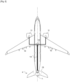
- another architecture of an aircraft propulsion system with BLI propulsion comprises, in addition to a BLI propeller 1 located at the tail of the fuselage 4, two conventional propellers of the turbojet type 11. These turbojets 11 are each located under a wing 12 and Together they generate between 60% and 80% of the aircraft's thrust.
- the BLI 1 propeller provides between 20% and 40% of the aircraft's thrust. In this mixed configuration, it is the turbojets 11 which generate the energy necessary to rotate the fan of the BLI 1 thruster. However, due to the significant distance between the turbojets 11 and the BLI 1 thruster, the energy distribution between the turbojets 11 and the BLI thruster 1 is carried out by an electrical coupling.
- the rotors of the turbojets 11 are mechanically coupled either to a common electric generator 13 or each to a respective electric generator.
- An electrical power wiring 14 connects the electrical generator(s) 13 to an electric motor 15 mechanically coupled to the fan of the BLI thruster 1 as described above.
- the transformation of the mechanical energy of the turbojets into electrical energy and then back into mechanical energy results in an energy loss comprised between 5% and 10% which negatively impacts the overall efficiency of the propulsion system and considerably reduces the benefit of having a BLI propellant to reduce the fuel consumption of the aircraft.
- the constituent elements of the electrical transmission chain, that is to say the generator(s) 13, the electric motor 15 and the wiring 14, add considerable excess weight to the aircraft.
- the electrical generators deliver constant power to the BLI thruster between the different phases of flight, this power being defined by the maximum absorption capacity of the electrical system.
- all three propulsion systems do not operate at their optimum between these different phases of flight.
- these propulsion systems only deliver limited gains in fuel consumption.
- the replacement of the electric transmission by a mechanical transmission which would limit the energy losses allocated to the transmission, is not possible due to the length of the transmission shaft between the wings 12 and the tail of fuselage 4, and the excessive excess weight that would result.
- the addition of a separate gas turbine to drive the fan of the BLI thruster, in addition to the turbojets 11, is not realistic due to the direct increase in maintenance costs that this would entail.
- the invention proposes an alternative to the BLI propulsion systems described above which makes it possible to significantly reduce the fuel consumption of the aircraft by optimizing the architecture of the propulsion system comprising a rear BLI thruster.
- the propulsion system according to the invention comprises in addition to a single rear BLI thruster 1 two turbojets 11 located on each side of the rear part of the fuselage 4 upstream of the rear BLI thruster 1.
- the proportion of the thrust provided by the rear BLI 1 propeller is at least one third of the total thrust of the aircraft.
- the diameter of the fan of the rear BLI thruster 1 is reduced to approximately 1.75 m instead of 3 m when the BLI thruster alone provides the thrust of the aircraft.
- the reduced size of the BLI propeller allows a greater inclination of the aircraft on takeoff.
- the two turbojets 11 have a gas flow diversion rate of between approximately 5 and 6.
- a mechanical transmission 16 ensures the distribution of energy between the turbojets 11 and the rear BLI thruster 1 in order to rotate the fan of the BLI thruster 1.
- the distribution of the power or thrust of the propulsion system between the different thrusters fluctuates only slightly between the flight phases of an aircraft at takeoff, during ascent, and in cruise mode.
- the share of the total thrust allocated to the rear BLI thruster 1 is between 20% and 80% depending on the desired level of compromise between the propulsive efficiency and the take-off inclination of the aircraft, therefore its maximum take-off weight, in optimizing the diameter of the rear BLI thruster 1.
- Each turbojet 11 is mechanically connected through a primary angle gear 17 to a transverse shaft 18.
- These primary angle gears 17 can be constituted, for example, by bevel gears or constant velocity joints.
- These transverse axes 18 are positioned transversely with respect to the longitudinal axis of the aircraft 19 on either side of the rear part of the fuselage 4.
- the transverse shafts 18 are mechanically connected on either side of a secondary angle gear 20 which can consist of a set of bevel gears whose output is connected to a longitudinal shaft 21 oriented in the axis of the aircraft 19.
- the longitudinal axis is mechanically connected to the fan 8 of the rear BLI thruster 1.
- the fan 8 of the BLI thruster 1 located at the tail of the fuselage is connected to the downstream part of the longitudinal shaft 21.
- a gearbox 22 can be inserted between the longitudinal shaft and the fan.
- the energy loss attributable to this mechanical transmission is only of the order of 1%, which is much lower than the 5 to 10% loss of electrical transmission.
- the weight of the mechanical transmission used in the propulsion system according to the invention is between 300 kg and 500 kg which is much lower than the weight of the electric transmission described above.
- the weight of the mechanical transmission of the propulsion system according to the invention is also lower than that of the motor unit of a thruster. BLI driven by a gas turbine. Indeed, in the concept according to the invention, only a fraction of the total power, corresponding to the propulsion of the BLI thruster (that is to say from 33 to 60%) passes through the mechanical transmission. In addition, the propulsion system according to the invention is much less noisy than a propulsion system in which the fan of the BLI propellant is rotated by a separate gas turbine installed outside the fuselage.
- the turbojets 11 are each fixed to a mast 23 which connects them to the rear part of the fuselage 4 where they are located.
- the transverse transmission shafts 18 are located at the rear of the masts 23 and parallel to them.
- the masts 23 of the turbojets 11 are profiled so that each of them can be integrated into a fairing 24 encompassing the masts and the transverse transmission shafts 18.
- This fairing 24 extends transversely to the axis of the fuselage 19 between the rear part of the fuselage 4 and the nacelles 25 encompassing the turbojets 11, and longitudinally in front of the masts 23 and behind the transverse transmission shafts 18.
- the masts 23 and the transverse transmission shafts 18 are streamlined in order to reduce drag aerodynamics of the aircraft.
- the fan 8 of the rear BLI thruster 1 is driven by a line of transmission shafts 18, 21 mechanically connecting it to the rotor of the turbojets 11.
- the specific architecture of the propulsion system according to the invention makes it possible to avoid thrust losses total in the event of failure of one of the thrusters 1 and 11.
- the turbojet 11 is rendered inoperative for any reason, the turbojet 11 remaining operational continues to deliver its own thrust and to ensure the training of the rear BLI thruster 1 which can thus contribute to the total thrust of the aircraft.
- the two turbojets 11 continue to deliver their own thrust.
- one or more safety devices 26 are integrated into the transmission chain connecting the rotors of the turbojets 11 to the fan 8 of the rear BLI thruster 1. These safety devices 26 decouple a driving part from a receiving part in the event of overload on a transmission line. transmission. They can be integrated into the longitudinal transmission shaft 21 or into each of the transverse transmission shafts 18 or onto the three transmission shafts. Independently or cumulatively with the safety devices 26 of the transmission shafts 18 and 21, safety devices 26 can be integrated into the rotors of the turbojets 11 and the rear BLI thruster 1.
- safety devices 26 can be selected from known mechanical devices making it possible to interrupt a transmission line in the event of blocking or overloading of the driving part or the receiving part connected together by the transmission line. These devices make it possible, in the event of overload, to ensure continuity of operation and/or to avoid damage to the mechanical elements of the devices to be protected.
- security devices There are different types of security devices that can be broadly classified into two categories. There are safety devices in which one of the components is calibrated to break in the event of overload, for example screw or shear pin torque limiters. In these devices, a mechanical element included in a coupler connecting two parts of a transmission shaft breaks in the event of overload. The mechanical connection connecting the motor member or several motor members to one or more receiving members is thus permanently interrupted until the replacement, generally easy, of the breaking element.
- the aircraft continues to benefit from partial thrust which is shared constantly between the remaining propellers. operational.
- the aircraft can thus remain operational and maneuverable until landing.
- propulsion comprising two turbojet engines suspended under the wings as illustrated in the figure 2 .
- This fuel economy is mainly obtained thanks to reduced energy losses due to the mechanical transmission between the turbojets and the rear BLI thruster, to a lighter transmission line, to fewer fluctuations in the proportion of the fan thrust of the BLI propellant between the different phases of flight, and the possibility of increasing the BLI effect on the propulsion of the aircraft.
- the reduction in fuel consumption obtained for an aircraft equipped with a propulsion system according to the invention whose rear BLI propeller produces 33% of the total thrust is between 4.1% and 4.6% compared to an aircraft equipped with a propulsion system as illustrated in figure 2 .
- the proportion of thrust provided by the rear BLI thruster is increased to 60%, then the reduction in fuel consumption can go up to a value between 4.9% and 5.4%.
Description
L'invention concerne les systèmes de propulsion d'aéronefs et plus spécifiquement leur composition et implantation sur un aéronef.The invention relates to aircraft propulsion systems and more specifically their composition and installation on an aircraft.
Les aéronefs commerciaux présentent le plus souvent une architecture générale comprenant un fuselage, une voilure comportant deux ailes et un empennage situé sur la partie arrière du fuselage. De tels aéronefs comportent en outre un système de propulsion comprenant un ou plusieurs groupes propulseurs, les plus communément employés étant des turboréacteurs. Les groupes propulseurs peuvent être implantés sur l'aéronef selon différentes configurations. Le plus couramment, ils sont suspendus au-dessous des ailes par des mats de support, mais ils peuvent aussi être fixés à l'arrière du fuselage par des mats ou au niveau de l'empennage.Commercial aircraft most often have a general architecture comprising a fuselage, a wing comprising two wings and a tail located on the rear part of the fuselage. Such aircraft further comprise a propulsion system comprising one or more propulsion groups, the most commonly used being turbojets. The power units can be installed on the aircraft in different configurations. Most commonly, they are suspended below the wings by support masts, but they can also be attached to the rear of the fuselage by masts or at the level of the empennage.
Lors du déplacement dans l'air de l'aéronef, ses surfaces externes influent sur l'écoulement de l'air. En particulier, lors du déplacement d'un profil aérodynamique dans l'air, une couche limite se crée à la surface de ce profil aérodynamique. Cette couche limite correspond à une zone dans laquelle la vitesse d'écoulement de l'air est ralentie par la viscosité de l'air en contact avec les surfaces du profil.As the aircraft moves through the air, its external surfaces affect the flow of air. In particular, when an airfoil moves through the air, a boundary layer is created on the surface of this airfoil. This boundary layer corresponds to an area in which the air flow speed is slowed by the viscosity of the air in contact with the profile surfaces.
En général, les groupes propulseurs sont configurés de façon à ne pas aspirer cette couche limite se créant sur les surfaces aérodynamiques de l'aéronef. Pour cela les groupes propulseurs sont le plus communément montés afin que leur entrée d'air soit située dans un flux d'air libre, c'est-à-dire peu ou pas perturbé par les surfaces de l'aéronef. C'est le cas lorsque par exemple les groupes propulseurs sont suspendus sous la voilure ou à distance du fuselage sur la partie arrière d'un aéronef.In general, the power units are configured so as not to suck up this boundary layer created on the aerodynamic surfaces of the aircraft. For this, the propulsion units are most commonly mounted so that their air inlet is located in a free air flow, that is to say little or not disturbed by the surfaces of the aircraft. This is the case when, for example, the propulsion units are suspended under the wing or at a distance from the fuselage on the rear part of an aircraft.
Néanmoins, l'ingestion par le groupe propulseur de cette couche limite présente certains avantages améliorant l'efficacité de la propulsion de ces aéronefs et réduisant leur consommation spécifique, c'est-à-dire la consommation de carburant rapportée à la poussée de l'aéronef. Afin de profiter de ces avantages un groupe propulseur peut ainsi être configuré pour ingérer la couche limite. De tels groupes propulseurs sont généralement désignés par l'acronyme BLI pour « Boundary Layer Ingestion ». Une possible configuration d'un groupe propulseur de type BLI sur un aéronef est son implantation en partie arrière du fuselage.Nevertheless, the ingestion by the propulsion unit of this boundary layer presents certain advantages improving the efficiency of the propulsion of these aircraft and reducing their specific consumption, that is to say the fuel consumption related to the thrust of the aircraft. aircraft. In order to benefit of these advantages a propulsion unit can thus be configured to ingest the boundary layer. Such power units are generally referred to by the acronym BLI for “Boundary Layer Ingestion”. A possible configuration of a BLI type power unit on an aircraft is its installation in the rear part of the fuselage.
Un exemple de groupe propulseur BLI implanté en partie arrière de fuselage est décrit dans la demande brevet
Quant à eux, les turboréacteurs comprennent une soufflante reliée en aval à l'axe d'une turbine à gaz qui forme le coeur du turboréacteur, l'axe de la turbine à gaz entrainant en rotation la soufflante et un générateur électrique. Chacun des turboréacteurs peut entrainer un générateur ou, comme divulgué dans le document de l'état de la technique référencé ci-dessus, ils peuvent entrainer mécaniquement un générateur implanté dans le fuselage au niveau des ailes. Dans cette configuration, le moteur électrique du propulseur BLI est alimenté par l'énergie électrique produite par ce générateur et un réseau de câbles électriques relient le générateur situé au niveau des ailes au moteur électrique situé en queue de fuselage. La transformation de l'énergie mécanique directement produite par les turboréacteurs en énergie électrique et son transport jusqu'au moteur électrique entraînant la soufflante du propulseur BLI conduisent à une perte de rendement énergétique de 5 à 10% ce qui réduit considérablement les bénéfices en économie d'énergie induits par l'utilisation d'un propulseur BLI arrière. De plus, la chaine de transmission électrique constituée par le générateur électrique, le moteur électrique et les câbles qui les relient, alourdit considérablement l'aéronef ce qui impacte aussi négativement la consommation de carburant et réduit d'autant plus les bénéfices attendus par l'implantation d'un propulseur BLI.As for them, turbojets include a fan connected downstream to the axis of a gas turbine which forms the heart of the turbojet, the axis of the gas turbine rotating the fan and an electric generator. Each of the turbojets can drive a generator or, as disclosed in the state of the art document referenced above, they can mechanically drive a generator installed in the fuselage at the level of the wings. In this configuration, the electric motor of the BLI thruster is powered by the electrical energy produced by this generator and a network of electrical cables connect the generator located at wing level to the electric motor located at the tail of the fuselage. The transformation of the mechanical energy directly produced by the turbojets into electrical energy and its transport to the electric motor driving the BLI propeller fan leads to a loss of energy efficiency of 5 to 10%, which considerably reduces the energy saving benefits induced by the use of a rear BLI thruster. In addition, the electric transmission chain constituted by the electric generator, the electric motor and the cables which connect them, considerably weighs down the aircraft which also negatively impacts fuel consumption and further reduces the benefits expected by the aircraft. installation of a BLI thruster.
Le remplacement de la transmission électrique par une transmission mécanique, qui entraine des pertes énergétiques moindres, n'est pas réaliste dans cette configuration car son poids due à la longue distance séparant les ailes de la queue du fuselage serait bien trop important. Tout aussi peu réaliste serait le remplacement du moteur électrique par une turbine à gaz distincte pour constituer l'unité motrice du propulseur BLI car cela générerait un surcoût de maintenance considérable.
Le but de de l'invention consiste donc à proposer un système de propulsion d'aéronef réduisant la consommation en carburant du système de propulsion d'aéronef en optimisant son rendement énergétique et en optimisant les avantages découlant de l'implantation en queue de fuselage d'un propulseur BLI.The aim of the invention therefore consists of proposing an aircraft propulsion system reducing the fuel consumption of the aircraft propulsion system by optimizing its energy efficiency and optimizing the advantages arising from the installation at the tail of the fuselage of a BLI thruster.
Ce but est atteint par l'objet de l'invention qui consiste en un aéronef comprenant un fuselage et une voilure, le fuselage comprenant une partie arrière de fuselage et une queue, ledit aéronef comprenant également un système de propulsion comprenant un premier dispositif de propulsion situé au niveau de la queue dudit fuselage et constitué d'au moins un propulseur BLI comprenant une soufflante ; un deuxième dispositif de propulsion constitué d'au moins un turboréacteur double flux ; et un dispositif de transmission couplant les premier et deuxième dispositifs de propulsion afin de transmettre une partie de l'énergie générée par le deuxième dispositif de propulsion au premier dispositif de propulsion, ainsi ledit deuxième système de propulsion génère l'énergie nécessaire pour entrainer en rotation la soufflante du propulseur de type BLI. Dans ledit système de propulsion, la poussée produite par les premier et deuxième dispositifs de propulsion contribue à générer la poussée totale de l'aéronef.This aim is achieved by the object of the invention which consists of an aircraft comprising a fuselage and a wing, the fuselage comprising a rear fuselage part and a tail, said aircraft also comprising a propulsion system comprising a first propulsion device located at the tail of said fuselage and consisting of at least one BLI propeller comprising a fan; a second propulsion device consisting of at least one turbofan engine; and a transmission device coupling the first and second propulsion devices in order to transmit part of the energy generated by the second propulsion device to the first propulsion device, thus said second propulsion system generates the energy necessary to drive rotation the BLI type propeller fan. In said propulsion system, the thrust produced by the first and second propulsion devices contributes to generating the total thrust of the aircraft.
Ainsi, le groupe propulseur d'aéronef selon l'invention est tel que le au moins un turboréacteur double flux constituant le deuxième dispositif de propulsion est situé au moins d'un côté de la partie arrière du fuselage entre la queue du fuselage et la voilure de l'aéronef ; le premier dispositif de propulsion génère entre 20% et 80% de la poussée totale de l'aéronef, et le dispositif de transmission intègre au moins un dispositif de sécurité intermittent apte à interrompre ou à réduire à un minimum la transmission d'énergie mécanique en cas de surcharge et à ramener la transmission d'énergie mécanique à un fonctionnement normal lorsque la surcharge disparaît.Thus, the aircraft propulsion unit according to the invention is such that the at least one turbojet constituting the second propulsion device is located at least on one side of the rear part of the fuselage between the tail of the fuselage and the wing of the aircraft; the first propulsion device generates between 20% and 80% of the total thrust of the aircraft, and the transmission device integrates at least one intermittent safety device capable of interrupting or reducing to a minimum the transmission of mechanical energy in case of overload and to return the transmission of mechanical energy to normal operation when the overload disappears.
L'agencement des turboréacteurs en partie arrière du fuselage à proximité de la queue où sont implantés le propulseur BLI et son unité motrice permet de réduire la distance sur laquelle l'énergie doit être transmise entre les turboréacteurs et le propulseur BLI. Cette disposition entraîne une réduction du poids du système permettant la transmission d'énergie des turboréacteurs au propulseur de type BLI et une diminution de la perte énergétique induite par cette transmission d'énergie.The arrangement of the turbojets in the rear part of the fuselage near the tail where the BLI thruster and its power unit are located makes it possible to reduce the distance over which the energy must be transmitted between the turbojets and the BLI thruster. This arrangement results in a reduction in the weight of the system allowing the transmission of energy from the turbojets to the BLI type propellant and a reduction in the energy loss induced by this energy transmission.
Dans une configuration particulièrement avantageuse du système de propulsion d'aéronef selon l'invention, le deuxième dispositif de propulsion comprend deux propulseurs classiques situés de part et d'autre de la partie arrière du fuselage de l'aéronef, et le premier dispositif de propulsion comprend un propulseur BLI.In a particularly advantageous configuration of the aircraft propulsion system according to the invention, the second propulsion device comprises two conventional thrusters located on either side of the rear part of the fuselage of the aircraft, and the first propulsion device includes a BLI thruster.
De préférence, dans le système de propulsion ledit dispositif de transmission est essentiellement de type mécanique.Preferably, in the propulsion system said transmission device is essentially of the mechanical type.
Plus particulièrement, dans le système de propulsion, le dispositif de transmission comprend au moins un arbre de transmission primaire relié mécaniquement au deuxième dispositif de propulsion et un arbre de transmission secondaire relié mécaniquement au premier dispositif de propulsion.More particularly, in the propulsion system, the transmission device comprises at least one primary transmission shaft mechanically connected to the second propulsion device and a secondary transmission shaft mechanically connected to the first propulsion device.
Avantageusement, l'arbre de transmission secondaire est relié mécaniquement par une de ses extrémités à la soufflante dudit propulseur BLI ; et le dispositif de transmission comprend deux arbres de transmission primaire chacun relié mécaniquement par une de leur extrémité à un des propulseurs classiques.Advantageously, the secondary transmission shaft is mechanically connected by one of its ends to the fan of said BLI thruster; and the transmission device comprises two primary transmission shafts each mechanically connected by one of their ends to one of the conventional thrusters.
De préférence, un dispositif de sécurité est intégré sur chacun des arbres de transmission primaire et secondaire et/ou au niveau des rotors des propulseurs classiques.Preferably, a safety device is integrated on each of the primary and secondary transmission shafts and/or at the rotors of conventional thrusters.
De préférence, les propulseurs classiques sont chacun reliés à la partie arrière de fuselage par un mât profilé et les arbres de transmission primaire sont montés en arrière des mâts et transversalement à l'axe général du fuselage.Preferably, the conventional thrusters are each connected to the rear part of the fuselage by a profiled mast and the primary transmission shafts are mounted behind the masts and transversely to the general axis of the fuselage.
D'autres caractéristiques et avantages de l'invention sont mis en évidence par la description ci-après d'exemples non-limitatifs de réalisation des différents aspects de l'invention. La description se réfère aux figures annexées qui sont aussi données à titre d'exemples de réalisation non limitatifs de l'invention :
- [
Fig.1 ] Lafigure 1 représente une vue de côté en demi-coupe d'un propulseur BLI ; - [
Fig. 2 ] Lafigure 2 représente une vue de dessus d'un aéronef comportant deux turboréacteurs et un propulseur BLI ; - [
Fig. 3 ] Lafigure 3 représente une vue de côté avec des coupes partielles d'une partie arrière d'aéronef comportant un système de propulsion selon l'invention ; - [
Fig. 4 ] Lafigure 4 représente une vue de dessus en demi-coupe de la partie arrière du fuselage avec un système de propulsion selon l'invention ; - [
Fig. 5 ] Lafigure 5 illustre un aéronef en vue de dessus équipé d'un système de propulsion selon l'invention.
- [
Fig.1 ] Therefigure 1 shows a half-section side view of a BLI thruster; - [
Fig. 2 ] Therefigure 2 represents a top view of an aircraft comprising two turbojets and a BLI propellant; - [
Fig. 3 ] ThereFigure 3 represents a side view with partial sections of a rear part of an aircraft comprising a propulsion system according to the invention; - [
Fig. 4 ] Therefigure 4 represents a half-section top view of the rear part of the fuselage with a propulsion system according to the invention; - [
Fig. 5 ] Therefigure 5 illustrates an aircraft in top view equipped with a propulsion system according to the invention.
Dans la suite, les positions axiales relatives des composants du groupe propulseur seront indiquées par rapport à la direction du flux de gaz traversant les propulseurs. Conventionnellement, un aéronef est mu par un système de propulsion comportant un ou plusieurs propulseurs. Ces propulseurs sont le plus souvent des turboréacteurs qui sont fixés généralement sous les ailes de l'aéronef. Néanmoins, les systèmes de propulsion d'aéronef peuvent aussi inclure un propulseur à ingestion de couche limite, aussi appelé propulseur BLI. BLI est l'acronyme de l'appellation anglaise « Boundary Layer Ingestion ». La position la plus appropriée pour un propulseur BLI est au niveau de la partie arrière du fuselage. En effet, positionner un propulseur BLI en queue de fuselage permet à la soufflante de celui-ci d'ingérer tout ou au moins une partie substantielle de la couche limite du fuselage avec une perte d'efficacité réduite de la soufflante due aux turbulences.In the following, the relative axial positions of the powertrain components will be indicated with respect to the direction of the gas flow. passing through the thrusters. Conventionally, an aircraft is powered by a propulsion system comprising one or more thrusters. These propellants are most often turbojet engines which are generally attached under the wings of the aircraft. However, aircraft propulsion systems can also include a boundary layer ingestion thruster, also called a BLI thruster. BLI is the acronym for “Boundary Layer Ingestion”. The most suitable position for a BLI thruster is at the rear of the fuselage. Indeed, positioning a BLI thruster at the tail of the fuselage allows its fan to ingest all or at least a substantial part of the boundary layer of the fuselage with a reduced loss of efficiency of the fan due to turbulence.
Typiquement, comme illustré sur la
Dans le cas où la propulsion de l'aéronef est assurée par le seul propulseur BLI 1, une turbine à gaz génère l'énergie nécessaire à entrainer la soufflante. Cette turbine à gaz peut être logée à l'intérieur de la partie arrière du fuselage 4 ou à l'extérieur du fuselage. Dans une telle configuration, si le propulseur BLI arrière ou la turbine à gaz qui l'entraine deviennent inopérants, l'aéronef subit une perte totale de propulsion. D'une part, lorsqu'une turbine à gaz est située à l'extérieur du fuselage, cela augmente la surface en contact avec le flux d'air environnant l'aéronef et donc sa trainée aérodynamique. D'autre part, la turbine additionnelle étant en configuration libre, elle est très bruyante. Par contre, si la turbine à gaz est située à l'intérieur du fuselage, une protection thermique est nécessaire. Cette configuration ne résout pas les problèmes de sécurité liés à une défaillance de la turbine à gaz entrainant la soufflante du propulseur BLI ou à une défaillance du propulseur BLI. L'accessibilité de la turbine à gaz interne est malaisée pour son entretien, et les problèmes liés aux défaillances d'un propulseur unique ne sont pas résolus. Un problème supplémentaire lié à l'utilisation d'un seul propulseur BLI pour assurer la propulsion de l'aéronef, est sa taille. Pour propulser un aéronef commercial, la taille du propulseur devient conséquente avec un diamètre de soufflante de l'ordre de 3 mètres. Ainsi la taille du propulseur BLI arrière limite l'angle d'inclinaison de l'aéronef au décollage et donc son poids maximum au décollage.In the case where the propulsion of the aircraft is provided by the
Comme mis en oeuvre dans un aéronef illustré à la
Comme illustré à la
L'invention propose une alternative aux systèmes de propulsion BLI décrits ci-dessus qui permet de réduire sensiblement la consommation en carburant de l'aéronef par une optimisation de l'architecture du système de propulsion comprenant un propulseur BLI arrière. Comme illustré aux
Dans cette configuration, la répartition de la puissance ou de la poussée du système de propulsion entre les différents propulseurs ne fluctue que faiblement entre les phases de vol d'un aéronef au décollage, durant l'ascension, et en régime de croisière. La part de la poussée totale dévolue au propulseur BLI arrière 1 est comprise entre 20% et 80% selon le niveau de compromis souhaité entre l'efficacité propulsive et l'inclinaison au décollage de l'aéronef, donc son poids maximum au décollage, en optimisant le diamètre du propulseur BLI arrière 1.In this configuration, the distribution of the power or thrust of the propulsion system between the different thrusters fluctuates only slightly between the flight phases of an aircraft at takeoff, during ascent, and in cruise mode. The share of the total thrust allocated to the
Chaque turboréacteur 11 est relié mécaniquement au travers d'un renvoi d'angle primaire 17 à un arbre transversal 18. Ces renvois d'angle primaires 17 peuvent être constitués, par exemple, par des pignons coniques ou des joints homocinétiques. Ces axes transversaux 18 sont positionnés transversalement par rapport à l'axe longitudinal de l'aéronef 19 de part et d'autre de la partie arrière du fuselage 4. Au niveau du fuselage, en amont du propulseur BLI 1, les arbres transversaux 18 sont reliés mécaniquement de part et d'autre d'un renvoi d'angle secondaire 20 qui peut être constitué d'un ensemble de pignons coniques dont la sortie est reliée à un arbre longitudinal 21 orienté dans l'axe de l'aéronef 19. Dans sa partie avale, l'axe longitudinal est relié mécaniquement à la soufflante 8 du propulseur BLI arrière 1. La soufflante 8 du propulseur BLI 1 situé en queue de fuselage est reliée à la partie avale de l'arbre longitudinal 21. Une boite de vitesse 22 peut être insérée entre l'arbre longitudinal et la soufflante. La perte d'énergie imputable à cette transmission mécanique n'est que de l'ordre de 1%, ce qui est très inférieur aux 5 à 10% de perte de la transmission électrique. En outre, le poids de la transmission mécanique mis en oeuvre dans le système de propulsion selon l'invention est compris entre 300 kg et 500 kg ce qui est bien inférieur au poids de la transmission électrique décrite ci-dessus.Each
Le poids de la transmission mécanique du système de propulsion selon l'invention est également inférieur à celui de l'unité motrice d'un propulseur BLI entrainé par une turbine à gaz. En effet, dans le concept selon l'invention, seulement une fraction de la puissance totale, correspondant à la propulsion du propulseur BLI (c'est-à-dire de 33 à 60%) passe par la transmission mécanique. De plus, le système de propulsion selon l'invention est bien moins bruyant qu'un système de propulsion dont la soufflante du propulseur BLI est mue en rotation par une turbine à gaz distincte implantée à l'extérieur du fuselage.The weight of the mechanical transmission of the propulsion system according to the invention is also lower than that of the motor unit of a thruster. BLI driven by a gas turbine. Indeed, in the concept according to the invention, only a fraction of the total power, corresponding to the propulsion of the BLI thruster (that is to say from 33 to 60%) passes through the mechanical transmission. In addition, the propulsion system according to the invention is much less noisy than a propulsion system in which the fan of the BLI propellant is rotated by a separate gas turbine installed outside the fuselage.
Dans le système de propulsion selon l'invention, les turboréacteurs 11 sont fixés chacun à un mât 23 qui les relient à la partie arrière du fuselage 4 où ils sont implantés. Les arbres de transmission transversaux 18 sont situés à l'arrière des mâts 23 et parallèlement à ceux-ci. Les mâts 23 des turboréacteurs 11 sont profilés de façon à ce que chacun d'eux puisse s'intégrer à un carénage 24 englobant les mâts et les arbres de transmission transversaux 18. Ce carénage 24 s'étend transversalement à l'axe du fuselage 19 entre la partie arrière du fuselage 4 et des nacelles 25 englobant les turboréacteurs 11, et longitudinalement en avant des mâts 23 et en arrière des arbres de transmission transversaux 18. Les mâts 23 et les arbres de transmission transversaux 18 sont carénés afin de réduire la trainée aérodynamique de l'aéronef.In the propulsion system according to the invention, the
La soufflante 8 du propulseur BLI arrière 1 est entrainée par une ligne d'arbres de transmissions 18, 21 la reliant mécaniquement au rotor des turboréacteurs 11. L'architecture spécifique du système de propulsion selon l'invention permet d'éviter les pertes de poussée totale en cas de défaillance d'un des propulseurs 1 et 11. Ainsi, si un des turboréacteurs 11 est rendu inopérant pour une raison quelconque, le turboréacteur 11 restant opérationnel continue à délivrer sa poussée propre et à assurer l'entrainement du propulseur BLI arrière 1 qui peuvent ainsi contribuer à la poussée totale de l'aéronef. De même, en cas de défaillance du propulseur BLI arrière 1, les deux turboréacteurs 11 continuent à délivrer leur poussée propre. Afin d'isoler un des propulseurs 1 et 11 en cas de défaillance de celui-ci, et d'assurer la continuité opérationnelle des propulseurs restants, un ou plusieurs dispositifs de sécurité 26 sont intégrés à la chaine de transmission reliant les rotors des turboréacteurs 11 à la soufflante 8 du propulseur BLI arrière 1. Ces dispositifs de sécurité 26 découplent une partie motrice d'une partie réceptrice en cas de surcharge sur une ligne de transmission. Ils peuvent être intégrés à l'arbre de transmission longitudinal 21 ou à chacun des arbres de transmission transversaux 18 ou sur les trois arbres de transmission. Indépendamment ou cumulativement aux dispositifs de sécurité 26 des arbres de transmissions 18 et 21, des dispositifs de sécurité 26 peuvent être intégrés aux rotors des turboréacteurs 11 et du propulseur BLI arrière 1.The
Ces dispositifs de sécurité 26 peuvent être sélectionnés parmi les dispositifs mécaniques connus permettant d'interrompre une ligne de transmission en cas de blocage ou de surcharge de la partie motrice ou de la partie réceptrice reliées entre elles par la ligne de transmission. Ces dispositifs permettent en cas de surcharge d'assurer une continuité de fonctionnement et/ou d'éviter d'endommager les éléments mécaniques des dispositifs à protéger. Il existe différents types de dispositifs de sécurité que l'on peut classer globalement en deux catégories. Il existe des dispositifs de sécurité dont un des composants est calibré pour se rompre en cas de surcharge, par exemple les limiteurs de couple à vis ou axe de cisaillement. Dans ces dispositifs, un élément mécanique compris dans un coupleur reliant deux parties d'un arbre de transmission casse en cas de surcharge. La liaison mécanique reliant l'organe moteur ou plusieurs organes moteurs à un ou plusieurs organes récepteurs est ainsi interrompue de façon permanente jusqu'au remplacement, généralement facile, de l'élément de rupture. Ainsi l'organe défaillant est séparé de la ligne de transmission qui continue à relier les organes mécaniques restant opérationnels. Il existe aussi des dispositifs de sécurité qui peuvent interrompre momentanément une chaine d'arbres de transmission en cas de surcharge de l'organe moteur ou de l'organe récepteur. Ainsi lorsque la surcharge disparaît la chaine de transmission revient à un fonctionnement normal. Dans certains de ces dispositifs de sécurité intermittents, la transmission du couple moteur est totalement interrompue durant la phase de surcharge alors que dans d'autres un couple minimum continue à être transmis ce qui permet d'éliminer certaines causes de surcharge sans endommagement du récepteur tel que la soufflante du propulseur BLI 1 ou du ou des turboréacteurs 11.These
Dans tous les cas, l'aéronef continue à bénéficier d'une poussée partielle qui est partagée de façon constante entre les propulseurs restant opérationnels. L'aéronef peut ainsi rester opérationnel et manoeuvrable jusqu'à son atterrissage.In all cases, the aircraft continues to benefit from partial thrust which is shared constantly between the remaining propellers. operational. The aircraft can thus remain operational and maneuverable until landing.
La combinaison des avantages obtenus par les différents aspects de l'invention permet d'obtenir une réduction de consommation pour un aéronef équipé d'un système de propulsion selon l'invention d'environ 5% comparé à un aéronef équipé d'un système de propulsion comprenant deux turboréacteurs suspendus sous les ailes tel qu'illustré à la
Bien que dans la description ci-dessus, les aspects particuliers de l'invention, notamment la mise en oeuvre d'une ligne de transmission compacte et essentiellement mécanique permise par les positions des turboréacteurs 11 proches du propulseur BLI 1, aient été décrits dans le contexte d'un système de propulsion comprenant un propulseur BLI 1 et deux turboréacteurs 11 implantés en partie arrière de fuselage, ils pourraient être mis en oeuvre dans d'autres configurations avec d'autres types de groupe propulseurs et une ligne de transmission les reliant différente de celle décrite ci-dessus.Although in the description above, the particular aspects of the invention, in particular the implementation of a compact and essentially mechanical transmission line made possible by the positions of the
Claims (7)
- An aircraft comprising a fuselage and a wing, the fuselage comprising a rear part of fuselage and a tail, said aircraft also comprising a propulsion system comprising:- a first propulsion device located at the rear part (4) of said fuselage and consisting of at least one BLI propeller (1) comprising a fan (8);- a second propulsion device consisting of at least one dual-flow turbojet engine (11); and- a transmission device coupling the first and second propulsion devices in order to transmit a part of the energy generated by the second propulsion device to the first propulsion device, said second propulsion device thus generating the energy required to rotate the fan (8) of the BLI propeller(s) (1);wherein the thrust produced by the first and second propulsion devices contributes to generating the total thrust of the aircraft;said propulsion system being such that: said at least one dual-flow turbojet engine (11) constituting the second propulsion device is located on at least one side of the rear part of the fuselage (4) between the tail of the fuselage and the wing of the aircraft, the first propulsion device generates between 20% and 80% of the total thrust of the aircraft;characterised in thatthe transmission device incorporates at least one intermittent safety device (26) capable of interrupting or reducing to a minimum the transmission of mechanical energy in the event of an overload and of returning the transmission of mechanical energy to normal operation when the overload disappears.
- The aircraft according to claim 1, wherein the second propulsion device comprises two conventional propellers (11) located on either side of the rear part of the fuselage (4) of the aircraft, and the first propulsion device comprises a BLI propeller (1).
- The aircraft according to any one of claims 1 or 2, wherein said transmission device is essentially of the mechanical type.
- The aircraft according to claim 3, wherein the transmission device comprises at least one primary transmission shaft (18) mechanically connected to the second propulsion device and a secondary transmission shaft (21) mechanically connected to the first propulsion device.
- The aircraft as claimed in claim 4, characterised in that:- the secondary transmission shaft (21) is mechanically connected at one end to the fan (8) of said BLI propeller (1); and- the transmission device comprises two primary transmission shafts (18), each mechanically connected by one of their ends to one of the conventional propellers (11).
- The aircraft according to claim 5, wherein a safety device (26) is integrated on each of the primary (18) and secondary (21) transmission shafts and/or at the rotors of the propellers (1; 11).
- The aircraft according to one of the preceding claims, wherein the conventional propellers (11) are each connected to the rear part of fuselage (4) by a profiled mast (23) and wherein the primary transmission shafts (18) are mounted behind said masts (23) and transversely to the general axis of the fuselage (19).
Applications Claiming Priority (1)
| Application Number | Priority Date | Filing Date | Title |
|---|---|---|---|
| FR1874098A FR3090578A1 (en) | 2018-12-24 | 2018-12-24 | BLI propulsion system with three rear thrusters |
Publications (2)
| Publication Number | Publication Date |
|---|---|
| EP3674208A1 EP3674208A1 (en) | 2020-07-01 |
| EP3674208B1 true EP3674208B1 (en) | 2023-10-25 |
Family
ID=67001913
Family Applications (1)
| Application Number | Title | Priority Date | Filing Date |
|---|---|---|---|
| EP19218098.2A Active EP3674208B1 (en) | 2018-12-24 | 2019-12-19 | Bli propulsion system with three rear propellers |
Country Status (4)
| Country | Link |
|---|---|
| US (1) | US20200216182A1 (en) |
| EP (1) | EP3674208B1 (en) |
| CN (1) | CN111348198A (en) |
| FR (1) | FR3090578A1 (en) |
Families Citing this family (3)
| Publication number | Priority date | Publication date | Assignee | Title |
|---|---|---|---|---|
| US11926410B2 (en) * | 2018-12-31 | 2024-03-12 | Jetzero, Inc. | Drag recovery scheme for nacelles |
| US20240017847A1 (en) * | 2022-07-15 | 2024-01-18 | Pratt & Whitney Canada Corp. | Aircraft propulsion system with intermittent combustion engine(s) |
| CN116374179B (en) * | 2023-06-05 | 2023-09-15 | 中国航发四川燃气涡轮研究院 | Series hybrid electric propulsion system |
Citations (1)
| Publication number | Priority date | Publication date | Assignee | Title |
|---|---|---|---|---|
| EP1267063B1 (en) * | 2001-06-14 | 2005-10-19 | Snecma | Variable cycle propulsion device using mechanical transmission for supersonic airplanes |
Family Cites Families (8)
| Publication number | Priority date | Publication date | Assignee | Title |
|---|---|---|---|---|
| FR1339141A (en) * | 1962-11-06 | 1963-10-04 | Messerschmitt Ag | Arrangement of jet thrusters at the end of the fuselage of an airplane |
| US5156353A (en) * | 1987-04-13 | 1992-10-20 | General Electric Company | Aircraft pylon |
| US7540450B2 (en) * | 2004-07-16 | 2009-06-02 | Pratt & Whitney Canada Corp. | Aircraft propulsion system |
| US8701381B2 (en) * | 2010-11-24 | 2014-04-22 | Rolls-Royce Corporation | Remote shaft driven open rotor propulsion system with electrical power generation |
| US9957055B2 (en) | 2015-09-21 | 2018-05-01 | General Electric Company | Aft engine for an aircraft |
| FR3041933B1 (en) * | 2015-10-05 | 2018-07-13 | Safran Aircraft Engines | AIRCRAFT WITH A PROPULSIVE ASSEMBLY COMPRISING A PROPELLER DOUBLET ON THE REAR OF THE FUSELAGE |
| FR3064028A1 (en) * | 2017-03-14 | 2018-09-21 | Airbus Operations | AIRCRAFT PROPELLER GROUP COMPRISING A BLOWER CONJOINLY DRIVEN BY TWO ENGINES |
| US11111029B2 (en) * | 2017-07-28 | 2021-09-07 | The Boeing Company | System and method for operating a boundary layer ingestion fan |
-
2018
- 2018-12-24 FR FR1874098A patent/FR3090578A1/en active Pending
-
2019
- 2019-12-18 US US16/719,020 patent/US20200216182A1/en not_active Abandoned
- 2019-12-19 EP EP19218098.2A patent/EP3674208B1/en active Active
- 2019-12-23 CN CN201911336607.6A patent/CN111348198A/en active Pending
Patent Citations (1)
| Publication number | Priority date | Publication date | Assignee | Title |
|---|---|---|---|---|
| EP1267063B1 (en) * | 2001-06-14 | 2005-10-19 | Snecma | Variable cycle propulsion device using mechanical transmission for supersonic airplanes |
Also Published As
| Publication number | Publication date |
|---|---|
| FR3090578A1 (en) | 2020-06-26 |
| EP3674208A1 (en) | 2020-07-01 |
| CN111348198A (en) | 2020-06-30 |
| US20200216182A1 (en) | 2020-07-09 |
Similar Documents
| Publication | Publication Date | Title |
|---|---|---|
| EP3674208B1 (en) | Bli propulsion system with three rear propellers | |
| EP3325345B1 (en) | Aircraft comprising a propulsion assembly including a fan on the rear of the fuselage | |
| EP3377732B1 (en) | Front part of a turbomachine | |
| CA2880146C (en) | Turbomachine comprising a plurality of fixed radial blades mounted upstream of the fan | |
| FR2908461A1 (en) | TURBOREACTOR RELIEF GENERATOR WITH DOUBLE FLOW | |
| EP3283747B1 (en) | Turbomachine with counter rotating propellers upstream of the gas generator | |
| FR2508552A1 (en) | COMBINED PROPELLER | |
| EP3817978B1 (en) | Propulsion system and aircraft propelled by such a propulsion system integrated at the rear of an aircraft fuselage | |
| CA2389531C (en) | Variable cycle propulsion device employing mechanical transmission for supersonic aircraft | |
| FR2493263A1 (en) | AIRCRAFT PROPULSION MEANS COMPRISING A NON-CARENE MULTIPALE PROPELLANT ROTOR | |
| WO2017060584A1 (en) | Aircraft comprising a propulsion assembly including a pair of propellers at the rear of the fuselage | |
| CA2585918C (en) | Drive installation for rotary-wing aircraft | |
| FR3064028A1 (en) | AIRCRAFT PROPELLER GROUP COMPRISING A BLOWER CONJOINLY DRIVEN BY TWO ENGINES | |
| WO1998047763A1 (en) | Traction system for propeller-driven transport aeroplane | |
| FR3043648A1 (en) | PROPELLANT VOILURE OF AN AIRCRAFT | |
| EP3587245B1 (en) | Propellant unit of an aircraft comprising an assembly of at least two coaxial shafts, one being connected to the fan and the other to the assembly of fixed vanes | |
| FR2951502A1 (en) | Turbomachine e.g. jet engine, for aircraft, has connection unit with air flow annular channel centered on longitudinal axle, where channel is traversed by oblique torque arms connecting internal units with streamline annual cases | |
| WO2017060585A1 (en) | Aircraft with multiple fan propulsion assembly fixed under the wing | |
| FR3039206A1 (en) | TURBOMACHINE FOR AIRCRAFT COMPRISING A FREE TURBINE IN THE PRIMARY FLOW | |
| CA2839248C (en) | Twin-spool turbine engine design with high-pressure compressor connected to the low-pressure turbine | |
| FR3067056B1 (en) | NON-CAREN ROTOR TYPE TURBOREACTOR | |
| FR3101614A1 (en) | Propulsion system for remote turbine engine aircraft | |
| FR3056556A1 (en) | AIRCRAFT WITH A TURBOMACHINE INTEGRATED WITH REAR FUSELAGE COMPRISING A PROPELLER SURROUNDING AN EXHAUST CASING | |
| FR3086001A1 (en) | AIRCRAFT PROPULSION SYSTEM WITH BLOWER PROVIDED AT REAR END OF FUSELAGE | |
| FR3082229A1 (en) | TURBOMACHINE WITH A PARTIAL COMPRESSION VANE |
Legal Events
| Date | Code | Title | Description |
|---|---|---|---|
| PUAI | Public reference made under article 153(3) epc to a published international application that has entered the european phase |
Free format text: ORIGINAL CODE: 0009012 |
|
| STAA | Information on the status of an ep patent application or granted ep patent |
Free format text: STATUS: THE APPLICATION HAS BEEN PUBLISHED |
|
| AK | Designated contracting states |
Kind code of ref document: A1 Designated state(s): AL AT BE BG CH CY CZ DE DK EE ES FI FR GB GR HR HU IE IS IT LI LT LU LV MC MK MT NL NO PL PT RO RS SE SI SK SM TR |
|
| AX | Request for extension of the european patent |
Extension state: BA ME |
|
| STAA | Information on the status of an ep patent application or granted ep patent |
Free format text: STATUS: REQUEST FOR EXAMINATION WAS MADE |
|
| 17P | Request for examination filed |
Effective date: 20201228 |
|
| RBV | Designated contracting states (corrected) |
Designated state(s): AL AT BE BG CH CY CZ DE DK EE ES FI FR GB GR HR HU IE IS IT LI LT LU LV MC MK MT NL NO PL PT RO RS SE SI SK SM TR |
|
| STAA | Information on the status of an ep patent application or granted ep patent |
Free format text: STATUS: EXAMINATION IS IN PROGRESS |
|
| 17Q | First examination report despatched |
Effective date: 20220411 |
|
| GRAP | Despatch of communication of intention to grant a patent |
Free format text: ORIGINAL CODE: EPIDOSNIGR1 |
|
| STAA | Information on the status of an ep patent application or granted ep patent |
Free format text: STATUS: GRANT OF PATENT IS INTENDED |
|
| INTG | Intention to grant announced |
Effective date: 20230609 |
|
| GRAS | Grant fee paid |
Free format text: ORIGINAL CODE: EPIDOSNIGR3 |
|
| GRAA | (expected) grant |
Free format text: ORIGINAL CODE: 0009210 |
|
| STAA | Information on the status of an ep patent application or granted ep patent |
Free format text: STATUS: THE PATENT HAS BEEN GRANTED |
|
| AK | Designated contracting states |
Kind code of ref document: B1 Designated state(s): AL AT BE BG CH CY CZ DE DK EE ES FI FR GB GR HR HU IE IS IT LI LT LU LV MC MK MT NL NO PL PT RO RS SE SI SK SM TR |
|
| REG | Reference to a national code |
Ref country code: GB Ref legal event code: FG4D Free format text: NOT ENGLISH |
|
| REG | Reference to a national code |
Ref country code: CH Ref legal event code: EP |
|
| REG | Reference to a national code |
Ref country code: DE Ref legal event code: R096 Ref document number: 602019039976 Country of ref document: DE |
|
| REG | Reference to a national code |
Ref country code: IE Ref legal event code: FG4D Free format text: LANGUAGE OF EP DOCUMENT: FRENCH |
|
| REG | Reference to a national code |
Ref country code: LT Ref legal event code: MG9D |
|
| REG | Reference to a national code |
Ref country code: NL Ref legal event code: MP Effective date: 20231025 |
|
| REG | Reference to a national code |
Ref country code: AT Ref legal event code: MK05 Ref document number: 1624422 Country of ref document: AT Kind code of ref document: T Effective date: 20231025 |
|
| PG25 | Lapsed in a contracting state [announced via postgrant information from national office to epo] |
Ref country code: NL Free format text: LAPSE BECAUSE OF FAILURE TO SUBMIT A TRANSLATION OF THE DESCRIPTION OR TO PAY THE FEE WITHIN THE PRESCRIBED TIME-LIMIT Effective date: 20231025 |
|
| PG25 | Lapsed in a contracting state [announced via postgrant information from national office to epo] |
Ref country code: GR Free format text: LAPSE BECAUSE OF FAILURE TO SUBMIT A TRANSLATION OF THE DESCRIPTION OR TO PAY THE FEE WITHIN THE PRESCRIBED TIME-LIMIT Effective date: 20240126 |
|
| PG25 | Lapsed in a contracting state [announced via postgrant information from national office to epo] |
Ref country code: IS Free format text: LAPSE BECAUSE OF FAILURE TO SUBMIT A TRANSLATION OF THE DESCRIPTION OR TO PAY THE FEE WITHIN THE PRESCRIBED TIME-LIMIT Effective date: 20240225 |
|
| PG25 | Lapsed in a contracting state [announced via postgrant information from national office to epo] |
Ref country code: LT Free format text: LAPSE BECAUSE OF FAILURE TO SUBMIT A TRANSLATION OF THE DESCRIPTION OR TO PAY THE FEE WITHIN THE PRESCRIBED TIME-LIMIT Effective date: 20231025 |
|
| PG25 | Lapsed in a contracting state [announced via postgrant information from national office to epo] |
Ref country code: AT Free format text: LAPSE BECAUSE OF FAILURE TO SUBMIT A TRANSLATION OF THE DESCRIPTION OR TO PAY THE FEE WITHIN THE PRESCRIBED TIME-LIMIT Effective date: 20231025 |
|
| PG25 | Lapsed in a contracting state [announced via postgrant information from national office to epo] |
Ref country code: ES Free format text: LAPSE BECAUSE OF FAILURE TO SUBMIT A TRANSLATION OF THE DESCRIPTION OR TO PAY THE FEE WITHIN THE PRESCRIBED TIME-LIMIT Effective date: 20231025 |
|
| PG25 | Lapsed in a contracting state [announced via postgrant information from national office to epo] |
Ref country code: LT Free format text: LAPSE BECAUSE OF FAILURE TO SUBMIT A TRANSLATION OF THE DESCRIPTION OR TO PAY THE FEE WITHIN THE PRESCRIBED TIME-LIMIT Effective date: 20231025 Ref country code: IS Free format text: LAPSE BECAUSE OF FAILURE TO SUBMIT A TRANSLATION OF THE DESCRIPTION OR TO PAY THE FEE WITHIN THE PRESCRIBED TIME-LIMIT Effective date: 20240225 Ref country code: GR Free format text: LAPSE BECAUSE OF FAILURE TO SUBMIT A TRANSLATION OF THE DESCRIPTION OR TO PAY THE FEE WITHIN THE PRESCRIBED TIME-LIMIT Effective date: 20240126 Ref country code: ES Free format text: LAPSE BECAUSE OF FAILURE TO SUBMIT A TRANSLATION OF THE DESCRIPTION OR TO PAY THE FEE WITHIN THE PRESCRIBED TIME-LIMIT Effective date: 20231025 Ref country code: BG Free format text: LAPSE BECAUSE OF FAILURE TO SUBMIT A TRANSLATION OF THE DESCRIPTION OR TO PAY THE FEE WITHIN THE PRESCRIBED TIME-LIMIT Effective date: 20240125 Ref country code: AT Free format text: LAPSE BECAUSE OF FAILURE TO SUBMIT A TRANSLATION OF THE DESCRIPTION OR TO PAY THE FEE WITHIN THE PRESCRIBED TIME-LIMIT Effective date: 20231025 Ref country code: PT Free format text: LAPSE BECAUSE OF FAILURE TO SUBMIT A TRANSLATION OF THE DESCRIPTION OR TO PAY THE FEE WITHIN THE PRESCRIBED TIME-LIMIT Effective date: 20240226 |