EP3674128A1 - Electrical vehicle system to discharge capacitors - Google Patents
Electrical vehicle system to discharge capacitors Download PDFInfo
- Publication number
- EP3674128A1 EP3674128A1 EP19217024.9A EP19217024A EP3674128A1 EP 3674128 A1 EP3674128 A1 EP 3674128A1 EP 19217024 A EP19217024 A EP 19217024A EP 3674128 A1 EP3674128 A1 EP 3674128A1
- Authority
- EP
- European Patent Office
- Prior art keywords
- capacitors
- heating device
- power rail
- discharge
- heater
- Prior art date
- Legal status (The legal status is an assumption and is not a legal conclusion. Google has not performed a legal analysis and makes no representation as to the accuracy of the status listed.)
- Withdrawn
Links
Images
Classifications
-
- B—PERFORMING OPERATIONS; TRANSPORTING
- B60—VEHICLES IN GENERAL
- B60L—PROPULSION OF ELECTRICALLY-PROPELLED VEHICLES; SUPPLYING ELECTRIC POWER FOR AUXILIARY EQUIPMENT OF ELECTRICALLY-PROPELLED VEHICLES; ELECTRODYNAMIC BRAKE SYSTEMS FOR VEHICLES IN GENERAL; MAGNETIC SUSPENSION OR LEVITATION FOR VEHICLES; MONITORING OPERATING VARIABLES OF ELECTRICALLY-PROPELLED VEHICLES; ELECTRIC SAFETY DEVICES FOR ELECTRICALLY-PROPELLED VEHICLES
- B60L3/00—Electric devices on electrically-propelled vehicles for safety purposes; Monitoring operating variables, e.g. speed, deceleration or energy consumption
- B60L3/0023—Detecting, eliminating, remedying or compensating for drive train abnormalities, e.g. failures within the drive train
- B60L3/0046—Detecting, eliminating, remedying or compensating for drive train abnormalities, e.g. failures within the drive train relating to electric energy storage systems, e.g. batteries or capacitors
-
- B—PERFORMING OPERATIONS; TRANSPORTING
- B60—VEHICLES IN GENERAL
- B60L—PROPULSION OF ELECTRICALLY-PROPELLED VEHICLES; SUPPLYING ELECTRIC POWER FOR AUXILIARY EQUIPMENT OF ELECTRICALLY-PROPELLED VEHICLES; ELECTRODYNAMIC BRAKE SYSTEMS FOR VEHICLES IN GENERAL; MAGNETIC SUSPENSION OR LEVITATION FOR VEHICLES; MONITORING OPERATING VARIABLES OF ELECTRICALLY-PROPELLED VEHICLES; ELECTRIC SAFETY DEVICES FOR ELECTRICALLY-PROPELLED VEHICLES
- B60L1/00—Supplying electric power to auxiliary equipment of vehicles
-
- H—ELECTRICITY
- H02—GENERATION; CONVERSION OR DISTRIBUTION OF ELECTRIC POWER
- H02J—ELECTRIC POWER NETWORKS; CIRCUIT ARRANGEMENTS OR SYSTEMS FOR SUPPLYING OR DISTRIBUTING ELECTRIC POWER; SYSTEMS FOR STORING ELECTRIC ENERGY
- H02J7/00—Circuit arrangements for charging or discharging batteries or for supplying loads from batteries
- H02J7/60—Circuit arrangements for charging or discharging batteries or for supplying loads from batteries including safety or protection arrangements
-
- B—PERFORMING OPERATIONS; TRANSPORTING
- B60—VEHICLES IN GENERAL
- B60L—PROPULSION OF ELECTRICALLY-PROPELLED VEHICLES; SUPPLYING ELECTRIC POWER FOR AUXILIARY EQUIPMENT OF ELECTRICALLY-PROPELLED VEHICLES; ELECTRODYNAMIC BRAKE SYSTEMS FOR VEHICLES IN GENERAL; MAGNETIC SUSPENSION OR LEVITATION FOR VEHICLES; MONITORING OPERATING VARIABLES OF ELECTRICALLY-PROPELLED VEHICLES; ELECTRIC SAFETY DEVICES FOR ELECTRICALLY-PROPELLED VEHICLES
- B60L1/00—Supplying electric power to auxiliary equipment of vehicles
- B60L1/02—Supplying electric power to auxiliary equipment of vehicles to electric heating circuits
-
- B—PERFORMING OPERATIONS; TRANSPORTING
- B60—VEHICLES IN GENERAL
- B60L—PROPULSION OF ELECTRICALLY-PROPELLED VEHICLES; SUPPLYING ELECTRIC POWER FOR AUXILIARY EQUIPMENT OF ELECTRICALLY-PROPELLED VEHICLES; ELECTRODYNAMIC BRAKE SYSTEMS FOR VEHICLES IN GENERAL; MAGNETIC SUSPENSION OR LEVITATION FOR VEHICLES; MONITORING OPERATING VARIABLES OF ELECTRICALLY-PROPELLED VEHICLES; ELECTRIC SAFETY DEVICES FOR ELECTRICALLY-PROPELLED VEHICLES
- B60L1/00—Supplying electric power to auxiliary equipment of vehicles
- B60L1/02—Supplying electric power to auxiliary equipment of vehicles to electric heating circuits
- B60L1/04—Supplying electric power to auxiliary equipment of vehicles to electric heating circuits fed by the power supply line
-
- B—PERFORMING OPERATIONS; TRANSPORTING
- B60—VEHICLES IN GENERAL
- B60L—PROPULSION OF ELECTRICALLY-PROPELLED VEHICLES; SUPPLYING ELECTRIC POWER FOR AUXILIARY EQUIPMENT OF ELECTRICALLY-PROPELLED VEHICLES; ELECTRODYNAMIC BRAKE SYSTEMS FOR VEHICLES IN GENERAL; MAGNETIC SUSPENSION OR LEVITATION FOR VEHICLES; MONITORING OPERATING VARIABLES OF ELECTRICALLY-PROPELLED VEHICLES; ELECTRIC SAFETY DEVICES FOR ELECTRICALLY-PROPELLED VEHICLES
- B60L58/00—Methods or circuit arrangements for monitoring or controlling batteries or fuel cells, specially adapted for electric vehicles
- B60L58/10—Methods or circuit arrangements for monitoring or controlling batteries or fuel cells, specially adapted for electric vehicles for monitoring or controlling batteries
- B60L58/24—Methods or circuit arrangements for monitoring or controlling batteries or fuel cells, specially adapted for electric vehicles for monitoring or controlling batteries for controlling the temperature of batteries
- B60L58/27—Methods or circuit arrangements for monitoring or controlling batteries or fuel cells, specially adapted for electric vehicles for monitoring or controlling batteries for controlling the temperature of batteries by heating
-
- B—PERFORMING OPERATIONS; TRANSPORTING
- B60—VEHICLES IN GENERAL
- B60R—VEHICLES, VEHICLE FITTINGS, OR VEHICLE PARTS, NOT OTHERWISE PROVIDED FOR
- B60R16/00—Electric or fluid circuits specially adapted for vehicles and not otherwise provided for; Arrangement of elements of electric or fluid circuits specially adapted for vehicles and not otherwise provided for
- B60R16/02—Electric or fluid circuits specially adapted for vehicles and not otherwise provided for; Arrangement of elements of electric or fluid circuits specially adapted for vehicles and not otherwise provided for electric constitutive elements
-
- B—PERFORMING OPERATIONS; TRANSPORTING
- B60—VEHICLES IN GENERAL
- B60R—VEHICLES, VEHICLE FITTINGS, OR VEHICLE PARTS, NOT OTHERWISE PROVIDED FOR
- B60R16/00—Electric or fluid circuits specially adapted for vehicles and not otherwise provided for; Arrangement of elements of electric or fluid circuits specially adapted for vehicles and not otherwise provided for
- B60R16/02—Electric or fluid circuits specially adapted for vehicles and not otherwise provided for; Arrangement of elements of electric or fluid circuits specially adapted for vehicles and not otherwise provided for electric constitutive elements
- B60R16/03—Electric or fluid circuits specially adapted for vehicles and not otherwise provided for; Arrangement of elements of electric or fluid circuits specially adapted for vehicles and not otherwise provided for electric constitutive elements for supply of electrical power to vehicle subsystems or for
- B60R16/033—Electric or fluid circuits specially adapted for vehicles and not otherwise provided for; Arrangement of elements of electric or fluid circuits specially adapted for vehicles and not otherwise provided for electric constitutive elements for supply of electrical power to vehicle subsystems or for characterised by the use of electrical cells or batteries
-
- H—ELECTRICITY
- H02—GENERATION; CONVERSION OR DISTRIBUTION OF ELECTRIC POWER
- H02J—ELECTRIC POWER NETWORKS; CIRCUIT ARRANGEMENTS OR SYSTEMS FOR SUPPLYING OR DISTRIBUTING ELECTRIC POWER; SYSTEMS FOR STORING ELECTRIC ENERGY
- H02J7/00—Circuit arrangements for charging or discharging batteries or for supplying loads from batteries
- H02J7/865—Battery or charger load switching, e.g. concurrent charging and load supply
-
- H—ELECTRICITY
- H05—ELECTRIC TECHNIQUES NOT OTHERWISE PROVIDED FOR
- H05B—ELECTRIC HEATING; ELECTRIC LIGHT SOURCES NOT OTHERWISE PROVIDED FOR; CIRCUIT ARRANGEMENTS FOR ELECTRIC LIGHT SOURCES, IN GENERAL
- H05B1/00—Details of electric heating devices
- H05B1/02—Automatic switching arrangements specially adapted to apparatus ; Control of heating devices
- H05B1/0227—Applications
- H05B1/023—Industrial applications
- H05B1/0236—Industrial applications for vehicles
-
- H—ELECTRICITY
- H02—GENERATION; CONVERSION OR DISTRIBUTION OF ELECTRIC POWER
- H02J—ELECTRIC POWER NETWORKS; CIRCUIT ARRANGEMENTS OR SYSTEMS FOR SUPPLYING OR DISTRIBUTING ELECTRIC POWER; SYSTEMS FOR STORING ELECTRIC ENERGY
- H02J7/00—Circuit arrangements for charging or discharging batteries or for supplying loads from batteries
- H02J7/34—Parallel operation in networks using both storage and other DC sources, e.g. providing buffering
- H02J7/345—Parallel operation in networks using both storage and other DC sources, e.g. providing buffering using capacitors as storage or buffering devices
-
- Y—GENERAL TAGGING OF NEW TECHNOLOGICAL DEVELOPMENTS; GENERAL TAGGING OF CROSS-SECTIONAL TECHNOLOGIES SPANNING OVER SEVERAL SECTIONS OF THE IPC; TECHNICAL SUBJECTS COVERED BY FORMER USPC CROSS-REFERENCE ART COLLECTIONS [XRACs] AND DIGESTS
- Y02—TECHNOLOGIES OR APPLICATIONS FOR MITIGATION OR ADAPTATION AGAINST CLIMATE CHANGE
- Y02T—CLIMATE CHANGE MITIGATION TECHNOLOGIES RELATED TO TRANSPORTATION
- Y02T10/00—Road transport of goods or passengers
- Y02T10/60—Other road transportation technologies with climate change mitigation effect
- Y02T10/70—Energy storage systems for electromobility, e.g. batteries
Definitions
- This invention relates to vehicle systems and has particular but non-exclusive application to electrically powered vehicles. In particular it relates to a method of discharging capacitors of a vehicle system.
- Vehicle electrical systems such as aircon, traction, and other systems often include bulky and high capacity capacitors. In certain circumstances these need to be discharged safely. Currently, additional circuitry/components are required to do this. This adds to cost and weight. It is an object of the invention to reduce costs and the need for expensive additional circuitry.
- a vehicle electrical system including a battery, the terminals of which supply positive and negative power rails, said battery being connected to one or more vehicle devices to supply power or charging thereto, said devices comprising or including capacitors, and further including at least one heating device, and including means to allow capacitor discharge to flow through the heating resistance.
- Said capacitor may be the bulk capacitors of an electrical vehicle.
- Said heater may be a (main) battery or bulk capacitor heater.
- Said heating resistance may be connected at each end to said power rails, and where one of the end of the heating resistance is connected to the respective power rail via a switch means, adapted to be switched between a connected state where said capacitors can discharge by allowing current to flow through the heating resistance, and a disconnected state.
- Said switch means may be part of the heater controller.
- Said switching means may be controlled by an input from an Electronic Control Unit (ECU).
- ECU Electronic Control Unit
- Said capacitance may be a bulk capacitor of an electric vehicle, located in series or directly with a switching device, and being electrically connected between said power rails, and where means to allow said capacitor to discharge comprises switching means connected between a point between capacitor and switching device, and a terminal of the heating resistance.
- the system may include a diode in series with said switching means electrically connected between said point and said terminal.
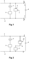
- Figure 1 shows a schematic circuit diagram showing two lines or rails 3/4 which are connected to either terminal of the vehicle battery. So one rail e.g. the top rail 3 is the positive rail and one rail 4 e.g. the bottom, is the negative rail.
- the positive rail 3 and the negative rail 4 supply vehicle systems and components further (not shown) on the right hand side of the figure as indicated by the arrows A. These systems and components may be e.g. aircon, traction, etc. and may include a capacitance or capacitor(s) 8 which need discharging.
- a bulk capacitor 1 which has connections between the battery voltage, i.e. spans the positive rail 3 and negative rail 4.
- a switching device 5 which may comprise e.g. of an IGBT and relay. This allows control of charging/discharge of the bulk capacitor 1.
- Vehicle systems such as aircon and traction systems often include e.g. large capacitors which in certain circumstances need to be discharged quickly e.g. for safety purposes during critical situations e.g. if the vehicle system indicates an imminent or potentially dangerous situation.
- one or more (e.g./ high voltage) capacitors represented by 8 needs to be brought to a safe level and this can be done by a control discharge command from the ECU (Electronic/Engine Control Unit).
- Both the discharge of the bulk capacitor 1 and/or the discharge of other capacitors 8 are provided by a relatively expensive device 6 which provides a discharge function from the capacitors 8 (allowing correct discharge path as shown by the arrows 2) and is controlled by a discharge signal 7.
- the present arrangement provides the capability to control the discharge in the bulk capacitor 1 and any further capacitors 8 located along the positive rail 3 and the negative rail 4 in a way that device 6 limits the instantaneous current and yet drives down the voltage fast enough to achieve a safe state within a given time ( ⁇ 60V in ⁇ 2 sec after trigger of discharge function by discharge signal 7).
- the safety discharge device 6 requires spreading of heat and is a cost adder and space adder.
- the switches involved are dedicated for only this purpose and since sleeping faults must be detected, the switches need to be activated for testing. This is a risk in the sense that the system can overheat in the event of a defect. This complexity is currently accepted by the market.
- a heater resistance in a vehicle heater device to also discharge capacitors 8.
- the vehicle heater device may be for example the heater which is used to warm up the capacitor bank and/or main battery but may be any heater.
- the heater device is also used according to the examples of the invention to discharge capacitors. Preferably with electric vehicles the heater used to prewarm the capacitor bank or main battery is used.
- the heater resistance is used to take the load when discharging the capacitor. So effectively, the heater resistance is used for two functions.
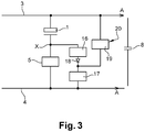
- FIG. 2 shows circuitry according to one aspect. It is similar to figure 1 and like components have the same reference numerals. Again, the figure shows two lines or rails 3, 4, which are connected to either terminal of the vehicle battery which may be regarded as being positioned on the right hand side.
- the top rail 3 is the positive rail and the bottom rail 4 is the negative rail.
- the positive rail 3 and the negative rail 4 also supply vehicle systems and components further (as indicated by the arrows A) which include capacitors represented by capacitor 8.
- a bulk capacitor 1 is provided as shown which has connections between the battery voltage, i.e. spans the positive and negative rail.
- a switching device 5 which may comprise e.g. of an IGBT and relay. This allows control of charging of the capacitor 8. It is to be noted that for the purpose of the example of invention where capacitors 8 are discharged, bulk capacitor 1 and switching device 5, are not essential features.
- Reference numeral 17 represent the heating resistance of a heating device e.g. to heat the bulk capacitors or main battery and is controlled by heater control stage 19.
- the heater device 17 and heater control stage 19 are connected to the battery/power supply e.g. in series.
- the heater control stage 19 has an input 20 which is a discharge control similar to the discharge signal 7 with reference to figure 1 and which may come from the ECU and is a command to discharge capacitors 8 to bring to e.g. safe levels in an e.g. emergency.
- the hater resistance is used to also discharge the capacitors 8 - thus by appropriate switching and control in heater control stage 19, the heater device 17 has additional functionality.
- the heater resistance as it is designed to take large current for heating purpose can discharge a lot of current in a small timespan and in this way the need for the extra device 6 is eliminated saving cost of the component.
- the slow discharge path is formed by the heater control stage 19 and the heater device 17. During this time, the heater control stage 19 is adapted to provide and control discharge from capacitors.
- the heater device 17 and heater control stage 19 can be tested as part of the heater function or be tested to detect sleeping faults.
- the robustness of the heater device 17 is way superior to the discharge circuits currently on the market. Since the heater device 17 is embedded in the system it is capable of the required reliability that is not achievable with remotely connected devices
- Figure 3 shows a further enhanced embodiment which can be provided for an electrical vehicle with a bulk capacitor. It is similar to figure 2 but also includes a connection from a point (marked X in the figure between one side of the charger/bulk capacitor 1 and the switching device 5), via a switching device 16 with diode 18, to the heater device 17. This provides the capability to take power from positive rail 3 and negative rail 4 to discharge the bulk capacitor 1 in the charger (in addition to along the positive rail 3 and negative rail 4) in the vehicle via the heater control stage 19. Again, appropriate control signal (e.g. form the ECU) can be used to control the heater (via switching) to allow discharge of the bulk capacitor 1.
- appropriate control signal e.g. form the ECU
- this arrangement may be used to control discharge from the bulk capacitor 1 and or the other (system) capacitors 8.
- the complexity and failure modes, the cost and the dynamic behavior are improved.
- the robust heater is reused to save the presently used discharge solutions.
Landscapes
- Engineering & Computer Science (AREA)
- Power Engineering (AREA)
- Mechanical Engineering (AREA)
- Transportation (AREA)
- Life Sciences & Earth Sciences (AREA)
- Sustainable Development (AREA)
- Sustainable Energy (AREA)
- Electric Propulsion And Braking For Vehicles (AREA)
- Secondary Cells (AREA)
- Air-Conditioning For Vehicles (AREA)
Abstract
Description
- This invention relates to vehicle systems and has particular but non-exclusive application to electrically powered vehicles. In particular it relates to a method of discharging capacitors of a vehicle system.
- Vehicle electrical systems such as aircon, traction, and other systems often include bulky and high capacity capacitors. In certain circumstances these need to be discharged safely. Currently, additional circuitry/components are required to do this. This adds to cost and weight. It is an object of the invention to reduce costs and the need for expensive additional circuitry.
- In one aspect of the invention is provided A vehicle electrical system including a battery, the terminals of which supply positive and negative power rails, said battery being connected to one or more vehicle devices to supply power or charging thereto, said devices comprising or including capacitors, and further including at least one heating device, and including means to allow capacitor discharge to flow through the heating resistance.
- Said capacitor may be the bulk capacitors of an electrical vehicle.
- Said heater may be a (main) battery or bulk capacitor heater.
- Said heating resistance may be connected at each end to said power rails, and where one of the end of the heating resistance is connected to the respective power rail via a switch means, adapted to be switched between a connected state where said capacitors can discharge by allowing current to flow through the heating resistance, and a disconnected state.
- Said switch means may be part of the heater controller.
- Said switching means may be controlled by an input from an Electronic Control Unit (ECU).
- Said capacitance may be a bulk capacitor of an electric vehicle, located in series or directly with a switching device, and being electrically connected between said power rails, and where means to allow said capacitor to discharge comprises switching means connected between a point between capacitor and switching device, and a terminal of the heating resistance.
- The system may include a diode in series with said switching means electrically connected between said point and said terminal.
- The present invention is now described by way of example with reference to the accompanying drawings in which:
-
Figure 1 shows a prior art system to discharge capacitors; -
Figure 2 shows a system according to one example; and -
Figure 3 shows a system according to a further refined example. -
Figure 1 shows a schematic circuit diagram showing two lines orrails 3/4 which are connected to either terminal of the vehicle battery. So one rail e.g. thetop rail 3 is the positive rail and onerail 4 e.g. the bottom, is the negative rail. Thepositive rail 3 and thenegative rail 4 supply vehicle systems and components further (not shown) on the right hand side of the figure as indicated by the arrows A. These systems and components may be e.g. aircon, traction, etc. and may include a capacitance or capacitor(s) 8 which need discharging. - In the case of electrically powered vehicles, there is typically included a
bulk capacitor 1 which has connections between the battery voltage, i.e. spans thepositive rail 3 andnegative rail 4. In series with the capacitor is aswitching device 5 which may comprise e.g. of an IGBT and relay. This allows control of charging/discharge of thebulk capacitor 1. - Vehicle systems such as aircon and traction systems often include e.g. large capacitors which in certain circumstances need to be discharged quickly e.g. for safety purposes during critical situations e.g. if the vehicle system indicates an imminent or potentially dangerous situation. So to recap, one or more (e.g./ high voltage) capacitors represented by 8 needs to be brought to a safe level and this can be done by a control discharge command from the ECU (Electronic/Engine Control Unit).
- Both the discharge of the
bulk capacitor 1 and/or the discharge ofother capacitors 8 are provided by a relativelyexpensive device 6 which provides a discharge function from the capacitors 8 (allowing correct discharge path as shown by the arrows 2) and is controlled by adischarge signal 7. - So in other words, the present arrangement provides the capability to control the discharge in the
bulk capacitor 1 and anyfurther capacitors 8 located along thepositive rail 3 and thenegative rail 4 in a way thatdevice 6 limits the instantaneous current and yet drives down the voltage fast enough to achieve a safe state within a given time (<60V in < 2 sec after trigger of discharge function by discharge signal 7). - The
safety discharge device 6 requires spreading of heat and is a cost adder and space adder. The switches involved are dedicated for only this purpose and since sleeping faults must be detected, the switches need to be activated for testing. This is a risk in the sense that the system can overheat in the event of a defect. This complexity is currently accepted by the market. - According to aspects of the invention, use is made of a heater resistance in a vehicle heater device to also discharge
capacitors 8. The vehicle heater device may be for example the heater which is used to warm up the capacitor bank and/or main battery but may be any heater. The heater device is also used according to the examples of the invention to discharge capacitors. Preferably with electric vehicles the heater used to prewarm the capacitor bank or main battery is used. In an aspect of the invention the heater resistance is used to take the load when discharging the capacitor. So effectively, the heater resistance is used for two functions. -
Figure 2 shows circuitry according to one aspect. It is similar tofigure 1 and like components have the same reference numerals. Again, the figure shows two lines orrails top rail 3 is the positive rail and thebottom rail 4 is the negative rail. Thepositive rail 3 and thenegative rail 4 also supply vehicle systems and components further (as indicated by the arrows A) which include capacitors represented bycapacitor 8. In electrical vehicles, abulk capacitor 1 is provided as shown which has connections between the battery voltage, i.e. spans the positive and negative rail. In series with thecapacitor 8 is aswitching device 5 which may comprise e.g. of an IGBT and relay. This allows control of charging of thecapacitor 8. It is to be noted that for the purpose of the example of invention wherecapacitors 8 are discharged,bulk capacitor 1 and switchingdevice 5, are not essential features. -
Reference numeral 17 represent the heating resistance of a heating device e.g. to heat the bulk capacitors or main battery and is controlled byheater control stage 19. Theheater device 17 andheater control stage 19 are connected to the battery/power supply e.g. in series. Theheater control stage 19 has aninput 20 which is a discharge control similar to thedischarge signal 7 with reference tofigure 1 and which may come from the ECU and is a command to dischargecapacitors 8 to bring to e.g. safe levels in an e.g. emergency. - So, in aspects of the invention the hater resistance is used to also discharge the capacitors 8 - thus by appropriate switching and control in
heater control stage 19, theheater device 17 has additional functionality. The heater resistance as it is designed to take large current for heating purpose can discharge a lot of current in a small timespan and in this way the need for theextra device 6 is eliminated saving cost of the component. The slow discharge path is formed by theheater control stage 19 and theheater device 17. During this time, theheater control stage 19 is adapted to provide and control discharge from capacitors. - The
heater device 17 andheater control stage 19 can be tested as part of the heater function or be tested to detect sleeping faults. The robustness of theheater device 17 is way superior to the discharge circuits currently on the market. Since theheater device 17 is embedded in the system it is capable of the required reliability that is not achievable with remotely connected devices -
Figure 3 shows a further enhanced embodiment which can be provided for an electrical vehicle with a bulk capacitor. It is similar tofigure 2 but also includes a connection from a point (marked X in the figure between one side of the charger/bulk capacitor 1 and the switching device 5), via aswitching device 16 withdiode 18, to theheater device 17. This provides the capability to take power frompositive rail 3 andnegative rail 4 to discharge thebulk capacitor 1 in the charger (in addition to along thepositive rail 3 and negative rail 4) in the vehicle via theheater control stage 19. Again, appropriate control signal (e.g. form the ECU) can be used to control the heater (via switching) to allow discharge of thebulk capacitor 1. - Of course, this arrangement may be used to control discharge from the
bulk capacitor 1 and or the other (system)capacitors 8. - The complexity and failure modes, the cost and the dynamic behavior are improved. The robust heater is reused to save the presently used discharge solutions.
Claims (8)
- A vehicle electrical system comprising:a positive power rail (3) connectable to a positive terminal of a battery;a negative power rail (4) connectable to a negative terminal of the battery;one or more vehicle devices connected to said positive power rail (3) and said negative power rail (4) such that said one or more vehicle devices is supplied with power, or is charged by, said battery, wherein said one or more vehicle devices comprises capacitors (1,8);a heating device (17); andmeans (16,19,20) to allow capacitor discharge from said capacitors (1,8) to flow through the heating device (17).
- A system as claimed in claim 1, wherein said capacitors (1,8) are bulk capacitors (1) of an electrical vehicle.
- A system as claimed in claim 1, wherein said heating device (17) is a battery heater or a bulk capacitor heater.
- A system as claimed in claim 1, where said heating device (17) is connected at a first end to one of said positive power rail (3) and said negative power rail (4), and where a second end of said heating device is connected to the other of said positive power rail (3) and said negative power rail (4) via a switch means (19) which is adapted to be switched between a connected state where said capacitors (1,8) can discharge by allowing current to flow through the heating device (17), and a disconnected state.
- A system as claimed in claim 4, wherein said switch means (19) is part of a heater controller which controls said heating device (17).
- A system as claimed in claim 4, where said switch means (19) is controlled by an input (20) from an Electronic Control Unit (ECU).
- A system as claimed in claim 1, where said capacitors (1,8) are a bulk capacitor (1) of an electric vehicle, located in series or directly with a switching device (5), and being electrically connected between said positive power rail (3) and said negative power rail (4), and where said means to allow said capacitors (1,8) to discharge comprises switching means (16) connected between a point (X) between said bulk capacitor (1) and said switching device (5), and one end of the heating device (17).
- A system as claimed in claim 7 including a diode (18) in series with said switching means (16) electrically connected between said point (X) and said one end of said heating device (17).
Applications Claiming Priority (1)
| Application Number | Priority Date | Filing Date | Title |
|---|---|---|---|
| US16/234,764 US11101671B2 (en) | 2018-12-28 | 2018-12-28 | Electrical vehicle system to discharge capacitors |
Publications (1)
| Publication Number | Publication Date |
|---|---|
| EP3674128A1 true EP3674128A1 (en) | 2020-07-01 |
Family
ID=68944241
Family Applications (1)
| Application Number | Title | Priority Date | Filing Date |
|---|---|---|---|
| EP19217024.9A Withdrawn EP3674128A1 (en) | 2018-12-28 | 2019-12-17 | Electrical vehicle system to discharge capacitors |
Country Status (3)
| Country | Link |
|---|---|
| US (1) | US11101671B2 (en) |
| EP (1) | EP3674128A1 (en) |
| CN (1) | CN111376724B (en) |
Families Citing this family (2)
| Publication number | Priority date | Publication date | Assignee | Title |
|---|---|---|---|---|
| US20210066953A1 (en) * | 2019-08-28 | 2021-03-04 | Delphi Automotive Systems Luxembourg Sa | Systems and methods for smooth start up of vehicle onboard battery charger |
| US11498442B2 (en) * | 2019-09-17 | 2022-11-15 | Dr. Ing. H.C. F. Porsche Aktiengesellschaft | Systems and methods for noise cancellation in protective earth resistance check of vehicle onboard battery charger |
Citations (6)
| Publication number | Priority date | Publication date | Assignee | Title |
|---|---|---|---|---|
| US6072301A (en) * | 1998-10-20 | 2000-06-06 | Chrysler Corporation | Efficient resonant self-heating battery electric circuit |
| US20110241581A1 (en) * | 2008-12-11 | 2011-10-06 | Stefan Flock | Vehicle having a power supply device for an electric motor and method for supplying power to the electric motor |
| US8497031B2 (en) * | 2010-08-10 | 2013-07-30 | GM Global Technology Operations LLC | Combined heating and pre-charging function and hardware for propulsion batteries |
| WO2017154088A1 (en) * | 2016-03-08 | 2017-09-14 | 本田技研工業株式会社 | Hybrid vehicle control device |
| US20180272871A1 (en) * | 2016-09-08 | 2018-09-27 | Hitachi Construction Machinery Co., Ltd. | Regenerative braking device and dump truck |
| EP3670239A1 (en) * | 2018-12-20 | 2020-06-24 | Vitesco Technologies GmbH | Power supply network and hybrid vehicle |
Family Cites Families (8)
| Publication number | Priority date | Publication date | Assignee | Title |
|---|---|---|---|---|
| JP5011940B2 (en) | 2006-10-16 | 2012-08-29 | トヨタ自動車株式会社 | Power supply device and vehicle |
| US8049460B2 (en) | 2007-07-18 | 2011-11-01 | Tesla Motors, Inc. | Voltage dividing vehicle heater system and method |
| KR20120020554A (en) | 2010-08-30 | 2012-03-08 | 삼성전기주식회사 | Integrated charging device for electric vehicle |
| WO2014024708A1 (en) | 2012-08-07 | 2014-02-13 | 住友電気工業株式会社 | Industrial vehicle and power source device thereof |
| US20140265559A1 (en) * | 2013-03-15 | 2014-09-18 | Levant Power Corporation | Vehicular high power electrical system |
| DE102014218775A1 (en) | 2014-09-18 | 2016-03-24 | Bayerische Motoren Werke Aktiengesellschaft | More voltage memory |
| FR3036864B1 (en) | 2015-05-29 | 2017-06-02 | Peugeot Citroen Automobiles Sa | MULTIFUNCTIONAL ELECTRICAL DEVICE |
| FR3066655B1 (en) | 2017-05-19 | 2019-07-19 | Valeo Siemens Eautomotive France Sas | ELECTRIC CHARGER SYSTEM FOR ELECTRIC OR HYBRID VEHICLE |
-
2018
- 2018-12-28 US US16/234,764 patent/US11101671B2/en active Active
-
2019
- 2019-12-17 EP EP19217024.9A patent/EP3674128A1/en not_active Withdrawn
- 2019-12-30 CN CN201911389491.2A patent/CN111376724B/en active Active
Patent Citations (6)
| Publication number | Priority date | Publication date | Assignee | Title |
|---|---|---|---|---|
| US6072301A (en) * | 1998-10-20 | 2000-06-06 | Chrysler Corporation | Efficient resonant self-heating battery electric circuit |
| US20110241581A1 (en) * | 2008-12-11 | 2011-10-06 | Stefan Flock | Vehicle having a power supply device for an electric motor and method for supplying power to the electric motor |
| US8497031B2 (en) * | 2010-08-10 | 2013-07-30 | GM Global Technology Operations LLC | Combined heating and pre-charging function and hardware for propulsion batteries |
| WO2017154088A1 (en) * | 2016-03-08 | 2017-09-14 | 本田技研工業株式会社 | Hybrid vehicle control device |
| US20180272871A1 (en) * | 2016-09-08 | 2018-09-27 | Hitachi Construction Machinery Co., Ltd. | Regenerative braking device and dump truck |
| EP3670239A1 (en) * | 2018-12-20 | 2020-06-24 | Vitesco Technologies GmbH | Power supply network and hybrid vehicle |
Also Published As
| Publication number | Publication date |
|---|---|
| US11101671B2 (en) | 2021-08-24 |
| CN111376724B (en) | 2023-08-11 |
| US20200212690A1 (en) | 2020-07-02 |
| CN111376724A (en) | 2020-07-07 |
Similar Documents
| Publication | Publication Date | Title |
|---|---|---|
| US9440551B2 (en) | Precharging a motor vehicle high-voltage network | |
| KR102197254B1 (en) | Safe energy supply device for a vehicle | |
| US7768237B2 (en) | Simplified automatic discharge function for vehicles | |
| CN109075597B (en) | Relay device and power supply device | |
| CN103738197B (en) | A kind of charging method of bus capacitor used for electric vehicle | |
| US20080007190A1 (en) | Motor control apparatus and on-vehicle motor drive system | |
| KR20140114372A (en) | System and method for high voltage cable detection in hybrid vehicles | |
| US11742749B2 (en) | Device and method for discharging a DC link capacitor, power converter and vehicle | |
| EP2189733A1 (en) | Heater Controller and method for operating a heater controller | |
| US20170125995A1 (en) | Electricity storage system | |
| CN111902308B (en) | Method and device for operating a motor vehicle | |
| EP3674128A1 (en) | Electrical vehicle system to discharge capacitors | |
| US9527396B2 (en) | Abnormality detection device | |
| NO20151755A1 (en) | Method and apparatus for electrically charging a high-voltage battery from an AC power supply system | |
| CN110912385B (en) | Active discharge circuit, control method and device thereof and vehicle | |
| JP5573800B2 (en) | Ground fault detection device | |
| CN112292282A (en) | Bus discharge for electric or hybrid vehicles | |
| CN111384749B (en) | Vehicle electrical system used to charge capacitors | |
| US20260012032A1 (en) | Device and method for controlling the discharge of a dc link capacitor | |
| US11299115B2 (en) | Power storage unit control device | |
| JP7713164B2 (en) | Vehicle control device | |
| JP4210927B2 (en) | Vehicle occupant protection device | |
| CN109311397B (en) | Method and device for externally monitoring power electronic components | |
| JP2737211B2 (en) | Variable speed drive for three-phase AC motor | |
| JP2019187042A (en) | Discharge method and discharge device for smoothing capacitor |
Legal Events
| Date | Code | Title | Description |
|---|---|---|---|
| PUAI | Public reference made under article 153(3) epc to a published international application that has entered the european phase |
Free format text: ORIGINAL CODE: 0009012 |
|
| STAA | Information on the status of an ep patent application or granted ep patent |
Free format text: STATUS: THE APPLICATION HAS BEEN PUBLISHED |
|
| AK | Designated contracting states |
Kind code of ref document: A1 Designated state(s): AL AT BE BG CH CY CZ DE DK EE ES FI FR GB GR HR HU IE IS IT LI LT LU LV MC MK MT NL NO PL PT RO RS SE SI SK SM TR |
|
| AX | Request for extension of the european patent |
Extension state: BA ME |
|
| STAA | Information on the status of an ep patent application or granted ep patent |
Free format text: STATUS: REQUEST FOR EXAMINATION WAS MADE |
|
| 17P | Request for examination filed |
Effective date: 20210111 |
|
| RBV | Designated contracting states (corrected) |
Designated state(s): AL AT BE BG CH CY CZ DE DK EE ES FI FR GB GR HR HU IE IS IT LI LT LU LV MC MK MT NL NO PL PT RO RS SE SI SK SM TR |
|
| STAA | Information on the status of an ep patent application or granted ep patent |
Free format text: STATUS: EXAMINATION IS IN PROGRESS |
|
| RAP1 | Party data changed (applicant data changed or rights of an application transferred) |
Owner name: DR.ING. H.C. F. PORSCHE AKTIENGESELLSCHAFT |
|
| 17Q | First examination report despatched |
Effective date: 20210514 |
|
| STAA | Information on the status of an ep patent application or granted ep patent |
Free format text: STATUS: THE APPLICATION IS DEEMED TO BE WITHDRAWN |
|
| 18D | Application deemed to be withdrawn |
Effective date: 20210925 |