EP3674084A1 - Liquid discharge apparatus, dyeing apparatus, and head drive method - Google Patents
Liquid discharge apparatus, dyeing apparatus, and head drive method Download PDFInfo
- Publication number
- EP3674084A1 EP3674084A1 EP19197152.2A EP19197152A EP3674084A1 EP 3674084 A1 EP3674084 A1 EP 3674084A1 EP 19197152 A EP19197152 A EP 19197152A EP 3674084 A1 EP3674084 A1 EP 3674084A1
- Authority
- EP
- European Patent Office
- Prior art keywords
- discharge
- liquid
- head
- pulse
- drive waveform
- Prior art date
- Legal status (The legal status is an assumption and is not a legal conclusion. Google has not performed a legal analysis and makes no representation as to the accuracy of the status listed.)
- Withdrawn
Links
- 239000007788 liquid Substances 0.000 title claims abstract description 79
- 238000004043 dyeing Methods 0.000 title claims description 11
- 238000000034 method Methods 0.000 title claims description 10
- 238000007599 discharging Methods 0.000 claims abstract description 11
- 230000005499 meniscus Effects 0.000 claims abstract description 6
- 238000012423 maintenance Methods 0.000 description 6
- 230000007547 defect Effects 0.000 description 5
- 230000001360 synchronised effect Effects 0.000 description 4
- 230000008719 thickening Effects 0.000 description 4
- 230000008859 change Effects 0.000 description 3
- 238000012545 processing Methods 0.000 description 3
- 229920000742 Cotton Polymers 0.000 description 2
- 230000009471 action Effects 0.000 description 2
- 238000010586 diagram Methods 0.000 description 2
- 238000001035 drying Methods 0.000 description 2
- 239000000975 dye Substances 0.000 description 2
- 239000004744 fabric Substances 0.000 description 2
- 239000000463 material Substances 0.000 description 2
- 239000002184 metal Substances 0.000 description 2
- 238000012805 post-processing Methods 0.000 description 2
- 238000009958 sewing Methods 0.000 description 2
- 230000001052 transient effect Effects 0.000 description 2
- 210000002268 wool Anatomy 0.000 description 2
- 230000015572 biosynthetic process Effects 0.000 description 1
- 238000006243 chemical reaction Methods 0.000 description 1
- 238000004140 cleaning Methods 0.000 description 1
- 239000012050 conventional carrier Substances 0.000 description 1
- 230000003111 delayed effect Effects 0.000 description 1
- 230000001419 dependent effect Effects 0.000 description 1
- 238000001514 detection method Methods 0.000 description 1
- 230000000694 effects Effects 0.000 description 1
- 238000011010 flushing procedure Methods 0.000 description 1
- 239000003365 glass fiber Substances 0.000 description 1
- 230000020169 heat generation Effects 0.000 description 1
- 239000000314 lubricant Substances 0.000 description 1
- 230000008531 maintenance mechanism Effects 0.000 description 1
- 230000000873 masking effect Effects 0.000 description 1
- 239000000203 mixture Substances 0.000 description 1
- 230000003287 optical effect Effects 0.000 description 1
- 229920000642 polymer Polymers 0.000 description 1
- 230000008569 process Effects 0.000 description 1
- 230000004044 response Effects 0.000 description 1
- 239000007787 solid Substances 0.000 description 1
- 239000004753 textile Substances 0.000 description 1
- 238000009941 weaving Methods 0.000 description 1
- 238000004804 winding Methods 0.000 description 1
Images




Classifications
-
- B—PERFORMING OPERATIONS; TRANSPORTING
- B41—PRINTING; LINING MACHINES; TYPEWRITERS; STAMPS
- B41J—TYPEWRITERS; SELECTIVE PRINTING MECHANISMS, i.e. MECHANISMS PRINTING OTHERWISE THAN FROM A FORME; CORRECTION OF TYPOGRAPHICAL ERRORS
- B41J2/00—Typewriters or selective printing mechanisms characterised by the printing or marking process for which they are designed
- B41J2/005—Typewriters or selective printing mechanisms characterised by the printing or marking process for which they are designed characterised by bringing liquid or particles selectively into contact with a printing material
- B41J2/01—Ink jet
- B41J2/015—Ink jet characterised by the jet generation process
- B41J2/04—Ink jet characterised by the jet generation process generating single droplets or particles on demand
- B41J2/045—Ink jet characterised by the jet generation process generating single droplets or particles on demand by pressure, e.g. electromechanical transducers
- B41J2/04501—Control methods or devices therefor, e.g. driver circuits, control circuits
- B41J2/04596—Non-ejecting pulses
-
- B—PERFORMING OPERATIONS; TRANSPORTING
- B41—PRINTING; LINING MACHINES; TYPEWRITERS; STAMPS
- B41J—TYPEWRITERS; SELECTIVE PRINTING MECHANISMS, i.e. MECHANISMS PRINTING OTHERWISE THAN FROM A FORME; CORRECTION OF TYPOGRAPHICAL ERRORS
- B41J3/00—Typewriters or selective printing or marking mechanisms characterised by the purpose for which they are constructed
- B41J3/407—Typewriters or selective printing or marking mechanisms characterised by the purpose for which they are constructed for marking on special material
- B41J3/4078—Printing on textile
-
- B—PERFORMING OPERATIONS; TRANSPORTING
- B41—PRINTING; LINING MACHINES; TYPEWRITERS; STAMPS
- B41J—TYPEWRITERS; SELECTIVE PRINTING MECHANISMS, i.e. MECHANISMS PRINTING OTHERWISE THAN FROM A FORME; CORRECTION OF TYPOGRAPHICAL ERRORS
- B41J2/00—Typewriters or selective printing mechanisms characterised by the printing or marking process for which they are designed
- B41J2/005—Typewriters or selective printing mechanisms characterised by the printing or marking process for which they are designed characterised by bringing liquid or particles selectively into contact with a printing material
- B41J2/01—Ink jet
- B41J2/015—Ink jet characterised by the jet generation process
- B41J2/04—Ink jet characterised by the jet generation process generating single droplets or particles on demand
- B41J2/045—Ink jet characterised by the jet generation process generating single droplets or particles on demand by pressure, e.g. electromechanical transducers
- B41J2/04501—Control methods or devices therefor, e.g. driver circuits, control circuits
- B41J2/04573—Timing; Delays
-
- B—PERFORMING OPERATIONS; TRANSPORTING
- B41—PRINTING; LINING MACHINES; TYPEWRITERS; STAMPS
- B41J—TYPEWRITERS; SELECTIVE PRINTING MECHANISMS, i.e. MECHANISMS PRINTING OTHERWISE THAN FROM A FORME; CORRECTION OF TYPOGRAPHICAL ERRORS
- B41J2/00—Typewriters or selective printing mechanisms characterised by the printing or marking process for which they are designed
- B41J2/005—Typewriters or selective printing mechanisms characterised by the printing or marking process for which they are designed characterised by bringing liquid or particles selectively into contact with a printing material
- B41J2/01—Ink jet
- B41J2/015—Ink jet characterised by the jet generation process
- B41J2/04—Ink jet characterised by the jet generation process generating single droplets or particles on demand
- B41J2/045—Ink jet characterised by the jet generation process generating single droplets or particles on demand by pressure, e.g. electromechanical transducers
- B41J2/04501—Control methods or devices therefor, e.g. driver circuits, control circuits
- B41J2/04581—Control methods or devices therefor, e.g. driver circuits, control circuits controlling heads based on piezoelectric elements
-
- B—PERFORMING OPERATIONS; TRANSPORTING
- B41—PRINTING; LINING MACHINES; TYPEWRITERS; STAMPS
- B41J—TYPEWRITERS; SELECTIVE PRINTING MECHANISMS, i.e. MECHANISMS PRINTING OTHERWISE THAN FROM A FORME; CORRECTION OF TYPOGRAPHICAL ERRORS
- B41J2/00—Typewriters or selective printing mechanisms characterised by the printing or marking process for which they are designed
- B41J2/005—Typewriters or selective printing mechanisms characterised by the printing or marking process for which they are designed characterised by bringing liquid or particles selectively into contact with a printing material
- B41J2/01—Ink jet
- B41J2/015—Ink jet characterised by the jet generation process
- B41J2/04—Ink jet characterised by the jet generation process generating single droplets or particles on demand
- B41J2/045—Ink jet characterised by the jet generation process generating single droplets or particles on demand by pressure, e.g. electromechanical transducers
- B41J2/04501—Control methods or devices therefor, e.g. driver circuits, control circuits
- B41J2/04588—Control methods or devices therefor, e.g. driver circuits, control circuits using a specific waveform
-
- D—TEXTILES; PAPER
- D06—TREATMENT OF TEXTILES OR THE LIKE; LAUNDERING; FLEXIBLE MATERIALS NOT OTHERWISE PROVIDED FOR
- D06P—DYEING OR PRINTING TEXTILES; DYEING LEATHER, FURS OR SOLID MACROMOLECULAR SUBSTANCES IN ANY FORM
- D06P5/00—Other features in dyeing or printing textiles, or dyeing leather, furs, or solid macromolecular substances in any form
Definitions
- the present disclosure relates to a liquid discharge apparatus, a dyeing apparatus, and a head driving method.
- a discharge timing is generated based on the amount of movement of a carriage on which a head is mounted and the amount of movement of a medium to which liquid is applied, and a discharge pulse is applied to the head with reference to the discharge timing.
- a drive waveform can include a micro vibrating pulse (non-discharge drive pulse) that slightly drives a pressure generating element to an extent that the liquid is not discharged from a nozzle, and the micro vibrating pulse is applied to the nozzle that is not to discharge the liquid.
- JP-4815364-B JP-2008-001084-A ) discloses such a configuration.
- JP-2018-526540-A discloses such a configuration.
- the discharge cycle (discharge period) of the liquid is proportional to the linear speed of the linear object.
- the linear speed of the linear object is not constant but fluctuates depending on the consumption etc. of the linear object.
- the discharge cycle fluctuates.
- the discharge cycle is long, there is a problem that a discharge defect easily occurs due to thickening of the liquid in the nozzle.
- an object of the present disclosure is to enable stable discharge even when the head is driven with a fluctuating discharge cycle.
- the liquid discharge apparatus includes a head including a row of a plurality of nozzles configured to discharge a liquid; and a drive waveform application unit.
- the drive waveform application unit is configured to generate a discharge timing in accordance with movement of a linear object to which the head applies the liquid, apply a drive waveform to the head based on the discharge timing, and apply a micro vibrating pulse to the head after application of a discharge pulse for discharging the liquid and before a subsequent discharge timing.
- the micro vibrating pulse is for vibrating a meniscus of the nozzle.
- a dyeing apparatus includes the head and the drive waveform application unit described above.
- a method for applying a drive waveform to a head including a row of a plurality of nozzles for discharging a liquid.
- the method includes generating a discharge timing in accordance with movement of a linear object to which the head applies the liquid, applying a drive waveform to the head based on the discharge timing, and applying a micro vibrating pulse to the head after application of a discharge pulse for discharging the liquid and before a subsequent discharge timing.
- FIG. 1 a liquid discharge apparatus according to an embodiment of this disclosure is described.
- the singular forms “a”, “an”, and “the” are intended to include the plural forms as well, unless the context clearly indicates otherwise.
- FIG. 1 is a schematic view of a liquid discharge apparatus 100.
- FIG. 2 is a view of a liquid application unit of the liquid discharge apparatus 100.
- FIG. 3 is a view of a row of heads of the liquid application unit as viewed from below.
- the liquid discharge apparatus 100 is an in-line embroidery machine.
- the liquid discharge apparatus 100 includes a supply reel 102 on which a thread 101 is wound, a liquid application unit 103, a fixing unit 104, a post-processing unit 105, and an embroidery head 106.
- the thread 101 drawn from the supply reel 102 is guided by rollers 108 and 109 and continuously stretched to the embroidery head 106.
- the liquid application unit 103 includes a plurality of heads 1 (1a to 1d), serving as liquid discharge devices, and a maintenance unit 2.
- the liquid application unit 103 discharges a liquid of a required color onto the thread 101 which is drawn out from the supply reel 102.
- the maintenance unit 2 incudes a plurality of individual maintenance units 20 (20a to 20d) to perform maintenance of the heads 1, respectively.
- the heads 1a to 1d discharge, for example, cyan (C), magenta (M), yellow (Y) and black (K) color liquids.
- each of the heads 1 (1a to 1d) includes a nozzle plate in which a plurality of nozzles 11 to discharge a liquid is formed. Specifically, on a face (hereinafter "nozzle face 12") of the nozzle plate, the plurality of nozzles 11 is lined in a nozzle row 10. Each head 1 is disposed such that the nozzle row 10 is oriented in (arrangement of the nozzles 11 matches) the direction of conveyance of the thread 101.
- the fixing unit 104 performs a fixing process (drying process) of the thread 101 to which the liquid is applied from the liquid application unit 103.
- the fixing unit 104 includes, for example, a heater such as an infrared irradiation device and a hot air sprayer, and heats the thread 101 to dry.
- the post-processing unit 105 includes, for example, a cleaning device that cleans the thread 101, a tension adjustment device that adjusts the tension of the thread 101, a feed amount detector that detects the amount of movement of the thread 101, and a lubricant application device that lubricates the surface of the thread 101.
- the embroidery head 106 embroiders a pattern, for example, on a cloth with the thread 101.
- liquid discharge apparatus in the present embodiment is an embroidery machine
- the present disclosure is not limited thereto. Aspects of the present disclosure are applicable to devices, such as weaving machines and sewing machines, that use linear objects such as threads. In addition, aspects of the present disclosure are applicable to apparatuses that print images on general sheet materials. Further, aspects of the present disclosure can be applied not only to apparatuses having a post-process, such as an embroidery machine, but also to dyeing apparatuses and the like that dye and wind threads, etc. as described later.
- “thread” includes glass fiber thread, wool thread, cotton thread, synthetic thread, metal thread, wool, cotton, polymer, mixed metal thread, yarn, filament, and linear objects (continuous base materials) to which liquid is applicable.
- the “thread” also includes braids and flat cords (flat braids).
- the liquid discharge apparatus 100 can include a controller configured similar to a general-purpose computer constructed of, for example, a central processing unit (CPU), a field-programmable gate array (FPGA), a random access memory (RAM), and a read only memory (ROM).
- a controller configured similar to a general-purpose computer constructed of, for example, a central processing unit (CPU), a field-programmable gate array (FPGA), a random access memory (RAM), and a read only memory (ROM).
- the CPU uses the RAM as a work area to execute various control programs stored on the ROM in order to control the operation of the liquid discharge apparatus 100.
- FIG. 4 is a block diagram illustrating components related to a drive waveform application unit according to the present embodiment.
- the head 1 includes a plurality of piezoelectric elements 13 as pressure generating elements that generate pressure for discharging the liquid from the plurality of nozzles 11.
- the drive waveform application unit to apply a drive waveform to the head 1 is implemented by a head controller 401, a drive waveform generation circuit 402, a waveform data storing unit 403, a head driver 410, and a discharge timing generation unit 404 to generate a discharge timing.
- the head controller 401 In response to a reception of a discharge timing pulse stb, the head controller 401 outputs a discharge synchronization signal LINE that triggers generation of the drive waveform, to the drive waveform generation circuit 402. Further, the head controller 401 outputs a discharge timing signal CHANGE equivalent to the amount of delay from the discharge synchronization signal LINE, to the drive waveform generation circuit 402.
- the drive waveform generation circuit 402 generates a common drive waveform signal Vcom at the timing based on the discharge synchronization signal LINE and the discharge timing signal CHANGE.
- the head controller 401 receives image data and generates a mask control signal MN based on the image data.
- the mask control signal MN is for selecting a waveform of the common drive waveform signal Vcom according to the size of the liquid droplet to be discharged from each nozzle 11 of the head 1.
- the mask control signal MN is a signal at a timing synchronized with the discharge timing signal CHANGE.
- the head controller 401 transmits image data SD, a synchronization clock signal SCK, a latch signal LT instructing latch of the image data, and the generated mask control signal MN to the head driver 410.
- the head driver 410 includes a shift register 411, a latch circuit 412, a gradation decoder 413, a level shifter 414, and an analog switch array 415.
- the shift register 411 receives the image data SD and the synchronization clock signal SCK transmitted from the head controller 401.
- the latch circuit 412 latches each value on the shift register 411 according to the latch signal LT transmitted from the head controller 401.
- the gradation decoder 413 decodes the value (image data SD) latched by the latch circuit 412 and the mask control signal MN and outputs the result.
- the level shifter 414 performs level conversion of a logic level voltage signal of the gradation decoder 413 to a level at which the analog switch AS of the analog switch array 415 can operate.
- the analog switch AS of the analog switch array 415 is turned on and off by the output received from the gradation decoder 413 via the level shifter 414.
- the analog switch AS is provided for each nozzle 11 of the head 1 and is connected to an individual electrode of the piezoelectric element 13 corresponding to each nozzle 11.
- the common drive waveform signal Vcom from the drive waveform generation circuit 402 is input.
- the timing of the mask control signal MN is synchronized with the timing of the common drive waveform signal Vcom.
- the analog switch AS is switched between on and off timely in accordance with the output from the gradation decoder 413 via the level shifter 414.
- the waveform to be applied to the piezoelectric element 13 corresponding to each nozzle 11 is selected from the drive waveforms forming the common drive waveform signal Vcom.
- the size of the liquid droplet discharged from the nozzle is controlled.
- the discharge timing generation unit 404 generates and outputs the discharge timing pulse stb each time the thread 101 is moved by a predetermined amount, based on the detection result of a rotary encoder 405 that detects the rotation amount of the roller 109 illustrated in FIG. 1 .
- the predetermined amount of movement of the thread 101 can be empirically obtained and stored in a memory.
- the rotary encoder 405 includes an encoder wheel 405a that rotates together with the roller 109 and an encoder sensor 405b that reads a slit of the encoder wheel 405a.
- the thread 101 is conveyed (moved) as consumed in the embroidery operation by the embroidery head 106 on the downstream side in the conveyance direction of the thread 101.
- the roller 109 guiding the thread 101 rotates to rotate the encoder wheel 405a of the rotary encoder 405.
- the encoder sensor 405b generates and outputs an encoder pulse proportional to the linear speed of the thread 101.
- the discharge timing generation unit 404 generates the discharge timing pulse stb based on the encoder pulse from the rotary encoder 405.
- the discharge timing pulse stb is used as the discharge timing of the head 1.
- the application of the liquid to the thread 101 is started as the thread 101 starts moving. Even if the linear speed of the thread 101 changes, deviations in the landing position of the droplets can be prevented because the interval of the discharge timing pulse stb changes according to the encoder pulse.
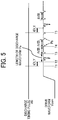
- FIG. 5 is a timing chart o the discharge timing pulse and the drive waveform.
- a discharge pulse Pa (a discharge waveform) for discharging the liquid is generated in the drive waveform.
- the discharge pulse Pa is applied to the head 1 at a timing T2 delayed by a time tDLY from when the discharge timing pulse stb is input at a timing T1.
- the micro vibrating pulse Pa is a drive pulse for vibrating the meniscus of the nozzle 11 to such an extent that the liquid is not discharged.
- the micro vibration operation for applying the micro vibrating pulse Pb is repeated at a predetermined micro vibration cycle (predetermined time interval) tVIB until a subsequent discharge timing pulse stb synchronized with the encoder pulse is generated (at a timing T5) or the drive waveform Vcom is slewed down.
- the predetermined time interval can be empirically obtained and stored in a memory.
- the micro vibration operation is stopped. Then, after elapse of the delay time tDLY from the discharge timing pulse stb, the discharge pulse Pa is applied, and the micro vibration operation of applying the micro vibrating pulse Pb is again started.
- the micro vibration operation is ended after the application of the micro vibrating pulse Pb completes and the drive waveform Vcom becomes an intermediate potential.
- the discharge pulse Pa is applied after elapse of the delay time tDLY from the discharge timing pulse stb. This is because the drive waveform Vcom changes sharply if the applied waveform is changed during application of the micro vibrating pulse Pb, which causes a discharge defect.
- the micro vibrating pulse is applied prior to the subsequent discharge timing.
- the state of the nozzle can be favorably maintained and stable discharge can be performed.
- the discharge cycle of the liquid from the head is proportional to the linear speed of the thread conveyed by the embroidery machine, but the linear speed of the thread conveyed by the embroidery machine is not necessarily constant.
- linear speed of the thread is approximately five to ten times as fast as the linear speed of the thread in "embroidery operation" for sewing with the thread on the cloth.
- the discharge cycle of the liquid is not constant. Additionally, when the discharge cycle is long, the liquid in or around the nozzle tends to thicken, and the possibility of a discharge defect increases. In addition, the maintenance operation (dummy discharge, flushing, etc.) for improving the discharge defect is performed with the conveyance of the thread stopped. Therefore, productivity is reduced if the maintenance operation is performed frequently.
- a micro vibrating pulse is applied to slightly vibrate the nozzle, thereby suppressing thickening of liquid in or around the nozzle.
- the delay time tDLY from the discharge timing pulse stb to the application of the discharge pulse Pa is equal to or longer than the waveform length of the micro vibrating pulse Pb.
- Such a configuration can prevent the occurrence of application timing of the discharge pulse Pa during application of the micro vibrating pulse Pb.
- the delay time tDLY is set to a sufficiently long time so that the discharge speed is not affected by the residual vibration by the micro vibrating pulse Pb. Then, the liquid can be discharged at a stable discharge speed.
- the delay time tDLY can be a variable value.
- micro vibrating pulse in the above embodiment is a micro-vibration drive waveform within the drive waveform
- a waveform exclusively for micro vibrating may be generated and used.
- the drive waveform application control may be configured as follows. In the micro vibration operation, instead of performing the above-mentioned mask control by the mask control signal MN, masking is turned off until the subsequent discharge timing.
- the numerical values in the column of drive frequency in FIG. 6 are respectively "3": normal discharge, "2": discharge defect (e.g. landing position deviation) in nozzles of 10 channels or more per row, "1": omission of discharge in 10 channels or more per row.
- the nozzle face is capped by a cap of the maintenance mechanism when the head is not driven to prevent thickening of the liquid in or around the nozzle due to drying, and the cap is removed from the nozzle face (decapping) when the head is driven. Since the nozzle face is decapped (exposed) at the time of liquid discharge, the thickening of liquid in the nozzle that does not discharge the liquid is prevented by the micro vibration operation, and the discharge stability is improved.
- the micro vibration cycle at the time of printing is synchronized with the discharge timing signal stb.
- the variations in the drive frequency are large (0 to several kHz).
- the frequency of the drive frequency bandwidth, which is large at the time of printing is as low as several hundreds Hz. According to the results in FIG. 6 , when the ambient temperature is 25 degrees centigrade, omission of discharge occurs in 2 minutes in a micro vibration cycle of 1 kHz, but normal discharge can continue for 6 minutes or longer in a micro vibration cycle of 10 kHz.
- a conceivable countermeasure is increasing the resolution of the encoder and raising the drive frequency, which is simple. Since the drive frequency increases in proportion to the resolution, the discharge stability is improved in the low frequency band of the drive frequency. However, the drive frequency increases in proportion to the resolution also in the high frequency band. Accordingly, such a countermeasure causes side effects. For example, the amount of heat generation of the head and the head driver drive circuit increase, and the discharge speed due to residual vibration changes in the high-frequency micro vibration operation.
- FIG. 7 is a schematic view of a dyeing apparatus 1000 according to another embodiment.
- the embroidery head 106 in the liquid discharge apparatus 100 illustrated in FIG. 1 is replaced with a take-up reel 107 for winding the thread 101 after dyeing.
- the dyeing apparatus 1000 supplies the thread 101 from the supply reel 102, discharges a liquid of a required color from the liquid application unit 103, dyes the thread 101 into a target color, and winds the dyed thread 101 with the take-up reel 107.
- the present invention can be implemented in any convenient form, for example using dedicated hardware, or a mixture of dedicated hardware and software.
- the present invention may be implemented as computer software implemented by one or more networked processing apparatuses.
- the processing apparatuses can include any suitably programmed apparatuses such as a general purpose computer, personal digital assistant, mobile telephone (such as a WAP or 3G-compliant phone) and so on. Since the present invention can be implemented as software, each and every aspect of the present invention thus encompasses computer software implementable on a programmable device.
- the computer software can be provided to the programmable device using any conventional carrier medium (carrier means).
- the carrier medium can include a transient carrier medium such as an electrical, optical, microwave, acoustic or radio frequency signal carrying the computer code.
- transient medium is a TCP/IP signal carrying computer code over an IP network, such as the Internet.
- the carrier medium can also comprise a storage medium for storing processor readable code such as a floppy disk, hard disk, CD ROM, magnetic tape device or solid state memory device.
Landscapes
- Engineering & Computer Science (AREA)
- Textile Engineering (AREA)
- Treatment Of Fiber Materials (AREA)
- Ink Jet (AREA)
- Particle Formation And Scattering Control In Inkjet Printers (AREA)
Abstract
Description
- The present disclosure relates to a liquid discharge apparatus, a dyeing apparatus, and a head driving method.
- For example, in a known method, a discharge timing is generated based on the amount of movement of a carriage on which a head is mounted and the amount of movement of a medium to which liquid is applied, and a discharge pulse is applied to the head with reference to the discharge timing. For example,
JP-2013-132752-A JP-4815364-B JP-2008-001084-A - Meanwhile, there are devices, such as embroidery machines, that feed thread from a thread supplying device and discharges liquid to the thread that is moving, to color the thread. In such an embroidery machine, the thread runs through a treatment section to an embroidery head, and embroidery is performed while the thread is colored. For example,
JP-2018-526540-A - When the device discharges the liquid from the head to a linear object such as thread while moving the linear object, the discharge cycle (discharge period) of the liquid is proportional to the linear speed of the linear object. However, the linear speed of the linear object is not constant but fluctuates depending on the consumption etc. of the linear object.
- Therefore, the discharge cycle fluctuates. When the discharge cycle is long, there is a problem that a discharge defect easily occurs due to thickening of the liquid in the nozzle.
- In view of the foregoing, an object of the present disclosure is to enable stable discharge even when the head is driven with a fluctuating discharge cycle.
- In order to achieve the above-described object, there is provided a liquid discharge apparatus as described in appended claims. Advantageous embodiments are defined by the dependent claims.
- Advantageously, the liquid discharge apparatus includes a head including a row of a plurality of nozzles configured to discharge a liquid; and a drive waveform application unit. The drive waveform application unit is configured to generate a discharge timing in accordance with movement of a linear object to which the head applies the liquid, apply a drive waveform to the head based on the discharge timing, and apply a micro vibrating pulse to the head after application of a discharge pulse for discharging the liquid and before a subsequent discharge timing. The micro vibrating pulse is for vibrating a meniscus of the nozzle.
- Advantageously, a dyeing apparatus includes the head and the drive waveform application unit described above.
- Further, there is provided a method for applying a drive waveform to a head including a row of a plurality of nozzles for discharging a liquid.
- Advantageously, the method includes generating a discharge timing in accordance with movement of a linear object to which the head applies the liquid, applying a drive waveform to the head based on the discharge timing, and applying a micro vibrating pulse to the head after application of a discharge pulse for discharging the liquid and before a subsequent discharge timing.
- Accordingly, stable liquid discharge can be performed even when the head is driven with a fluctuating discharge cycle.
- A more complete appreciation of the disclosure and many of the attendant advantages thereof will be readily obtained as the same becomes better understood by reference to the following detailed description when considered in connection with the accompanying drawings, wherein:
-
FIG. 1 is a schematic side view of a liquid discharge apparatus according to the present disclosure; -
FIG. 2 is a schematic view of a liquid application unit of the liquid discharge apparatus illustrated inFIG. 1 ; -
FIG. 3 is a plan view of a row of heads of the liquid application unit illustrated inFIG. 2 , as viewed from below; -
FIG. 4 is a block diagram illustrating components related to drive waveform application according to an embodiment of the present disclosure; -
FIG. 5 is a timing chart of a discharge timing pulse and a drive waveform generated in the configuration illustrated inFIG. 4 ; -
FIG. 6 is a table illustrating an example of relationship between decapping time of a nozzle face of the head illustrated inFIG. 3 and discharge stability in accordance with micro vibration frequencies; and -
FIG. 7 is a schematic view of a dyeing apparatus according to an embodiment of the present disclosure. - The accompanying drawings are intended to depict embodiments of the present invention and should not be interpreted to limit the scope thereof. The accompanying drawings are not to be considered as drawn to scale unless explicitly noted.
- In describing embodiments illustrated in the drawings, specific terminology is employed for the sake of clarity. However, the disclosure of this patent specification is not intended to be limited to the specific terminology so selected, and it is to be understood that each specific element includes all technical equivalents that operate in a similar manner and achieve a similar result.
- Referring now to the drawings, wherein like reference numerals designate identical or corresponding parts throughout the several views thereof, and particularly to
FIG. 1 , a liquid discharge apparatus according to an embodiment of this disclosure is described. As used herein, the singular forms "a", "an", and "the" are intended to include the plural forms as well, unless the context clearly indicates otherwise. -
FIG. 1 is a schematic view of aliquid discharge apparatus 100.FIG. 2 is a view of a liquid application unit of theliquid discharge apparatus 100.FIG. 3 is a view of a row of heads of the liquid application unit as viewed from below. - The
liquid discharge apparatus 100 is an in-line embroidery machine. Theliquid discharge apparatus 100 includes asupply reel 102 on which athread 101 is wound, aliquid application unit 103, afixing unit 104, apost-processing unit 105, and anembroidery head 106. - The
thread 101 drawn from thesupply reel 102 is guided byrollers embroidery head 106. - The
liquid application unit 103 includes a plurality of heads 1 (1a to 1d), serving as liquid discharge devices, and amaintenance unit 2. Theliquid application unit 103 discharges a liquid of a required color onto thethread 101 which is drawn out from thesupply reel 102. Themaintenance unit 2 incudes a plurality of individual maintenance units 20 (20a to 20d) to perform maintenance of theheads 1, respectively. Theheads 1a to 1d discharge, for example, cyan (C), magenta (M), yellow (Y) and black (K) color liquids. - As illustrated in
FIG. 3 , each of the heads 1 (1a to 1d) includes a nozzle plate in which a plurality ofnozzles 11 to discharge a liquid is formed. Specifically, on a face (hereinafter "nozzle face 12") of the nozzle plate, the plurality ofnozzles 11 is lined in anozzle row 10. Eachhead 1 is disposed such that thenozzle row 10 is oriented in (arrangement of thenozzles 11 matches) the direction of conveyance of thethread 101. - The
fixing unit 104 performs a fixing process (drying process) of thethread 101 to which the liquid is applied from theliquid application unit 103. Thefixing unit 104 includes, for example, a heater such as an infrared irradiation device and a hot air sprayer, and heats thethread 101 to dry. - The
post-processing unit 105 includes, for example, a cleaning device that cleans thethread 101, a tension adjustment device that adjusts the tension of thethread 101, a feed amount detector that detects the amount of movement of thethread 101, and a lubricant application device that lubricates the surface of thethread 101. - The embroidery head 106 embroiders a pattern, for example, on a cloth with the
thread 101. - Although the liquid discharge apparatus in the present embodiment is an embroidery machine, the present disclosure is not limited thereto. Aspects of the present disclosure are applicable to devices, such as weaving machines and sewing machines, that use linear objects such as threads. In addition, aspects of the present disclosure are applicable to apparatuses that print images on general sheet materials. Further, aspects of the present disclosure can be applied not only to apparatuses having a post-process, such as an embroidery machine, but also to dyeing apparatuses and the like that dye and wind threads, etc. as described later.
- Further, "thread" includes glass fiber thread, wool thread, cotton thread, synthetic thread, metal thread, wool, cotton, polymer, mixed metal thread, yarn, filament, and linear objects (continuous base materials) to which liquid is applicable. Thus, the "thread" also includes braids and flat cords (flat braids).
- The
liquid discharge apparatus 100 can include a controller configured similar to a general-purpose computer constructed of, for example, a central processing unit (CPU), a field-programmable gate array (FPGA), a random access memory (RAM), and a read only memory (ROM). For example, the CPU uses the RAM as a work area to execute various control programs stored on the ROM in order to control the operation of theliquid discharge apparatus 100. - Next, a configuration for drive waveform application according to the present embodiment is described with reference to
FIG. 4. FIG. 4 is a block diagram illustrating components related to a drive waveform application unit according to the present embodiment. - The
head 1 includes a plurality ofpiezoelectric elements 13 as pressure generating elements that generate pressure for discharging the liquid from the plurality ofnozzles 11. - The drive waveform application unit to apply a drive waveform to the
head 1 is implemented by ahead controller 401, a drivewaveform generation circuit 402, a waveformdata storing unit 403, ahead driver 410, and a dischargetiming generation unit 404 to generate a discharge timing. - In response to a reception of a discharge timing pulse stb, the
head controller 401 outputs a discharge synchronization signal LINE that triggers generation of the drive waveform, to the drivewaveform generation circuit 402. Further, thehead controller 401 outputs a discharge timing signal CHANGE equivalent to the amount of delay from the discharge synchronization signal LINE, to the drivewaveform generation circuit 402. - The drive
waveform generation circuit 402 generates a common drive waveform signal Vcom at the timing based on the discharge synchronization signal LINE and the discharge timing signal CHANGE. - The
head controller 401 receives image data and generates a mask control signal MN based on the image data. The mask control signal MN is for selecting a waveform of the common drive waveform signal Vcom according to the size of the liquid droplet to be discharged from eachnozzle 11 of thehead 1. The mask control signal MN is a signal at a timing synchronized with the discharge timing signal CHANGE. - Then, the
head controller 401 transmits image data SD, a synchronization clock signal SCK, a latch signal LT instructing latch of the image data, and the generated mask control signal MN to thehead driver 410. - The
head driver 410 includes ashift register 411, alatch circuit 412, agradation decoder 413, alevel shifter 414, and ananalog switch array 415. - The
shift register 411 receives the image data SD and the synchronization clock signal SCK transmitted from thehead controller 401. Thelatch circuit 412 latches each value on theshift register 411 according to the latch signal LT transmitted from thehead controller 401. - The
gradation decoder 413 decodes the value (image data SD) latched by thelatch circuit 412 and the mask control signal MN and outputs the result. Thelevel shifter 414 performs level conversion of a logic level voltage signal of thegradation decoder 413 to a level at which the analog switch AS of theanalog switch array 415 can operate. - The analog switch AS of the
analog switch array 415 is turned on and off by the output received from thegradation decoder 413 via thelevel shifter 414. The analog switch AS is provided for eachnozzle 11 of thehead 1 and is connected to an individual electrode of thepiezoelectric element 13 corresponding to eachnozzle 11. In addition, to the analog switch AS, the common drive waveform signal Vcom from the drivewaveform generation circuit 402 is input. In addition, as described above, the timing of the mask control signal MN is synchronized with the timing of the common drive waveform signal Vcom. - Therefore, the analog switch AS is switched between on and off timely in accordance with the output from the
gradation decoder 413 via thelevel shifter 414. With this operation, the waveform to be applied to thepiezoelectric element 13 corresponding to eachnozzle 11 is selected from the drive waveforms forming the common drive waveform signal Vcom. As a result, the size of the liquid droplet discharged from the nozzle is controlled. - The discharge
timing generation unit 404 generates and outputs the discharge timing pulse stb each time thethread 101 is moved by a predetermined amount, based on the detection result of arotary encoder 405 that detects the rotation amount of theroller 109 illustrated inFIG. 1 . The predetermined amount of movement of thethread 101 can be empirically obtained and stored in a memory. Therotary encoder 405 includes anencoder wheel 405a that rotates together with theroller 109 and anencoder sensor 405b that reads a slit of theencoder wheel 405a. - The
thread 101 is conveyed (moved) as consumed in the embroidery operation by theembroidery head 106 on the downstream side in the conveyance direction of thethread 101. As thethread 101 is conveyed, theroller 109 guiding thethread 101 rotates to rotate theencoder wheel 405a of therotary encoder 405. Then, theencoder sensor 405b generates and outputs an encoder pulse proportional to the linear speed of thethread 101. - The discharge
timing generation unit 404 generates the discharge timing pulse stb based on the encoder pulse from therotary encoder 405. The discharge timing pulse stb is used as the discharge timing of thehead 1. The application of the liquid to thethread 101 is started as thethread 101 starts moving. Even if the linear speed of thethread 101 changes, deviations in the landing position of the droplets can be prevented because the interval of the discharge timing pulse stb changes according to the encoder pulse. - Next, drive waveforms according to the present embodiment is described with reference to
FIG. 5. FIG. 5 is a timing chart o the discharge timing pulse and the drive waveform. - With reference to the discharge timing pulse stb from the discharge
timing generation unit 404 illustrated inFIG. 5 , a discharge pulse Pa (a discharge waveform) for discharging the liquid is generated in the drive waveform. Specifically, the discharge pulse Pa is applied to thehead 1 at a timing T2 delayed by a time tDLY from when the discharge timing pulse stb is input at a timing T1. - Then, at a timing T4 after elapse of a micro vibration cycle tVIB (time interval) from completion (a timing T3) of the application of the discharge pulse Pa for the entire wavelength thereof, application of a micro vibrating pulse Pb (micro-vibration drive waveform) is started. The micro vibrating pulse Pa is a drive pulse for vibrating the meniscus of the
nozzle 11 to such an extent that the liquid is not discharged. - The micro vibration operation for applying the micro vibrating pulse Pb is repeated at a predetermined micro vibration cycle (predetermined time interval) tVIB until a subsequent discharge timing pulse stb synchronized with the encoder pulse is generated (at a timing T5) or the drive waveform Vcom is slewed down. The predetermined time interval can be empirically obtained and stored in a memory.
- In a case where the micro vibrating pulse Pb is not being applied and the drive waveform Vcom has an intermediate potential at the time of generation of the discharge timing pulse stb, the micro vibration operation is stopped. Then, after elapse of the delay time tDLY from the discharge timing pulse stb, the discharge pulse Pa is applied, and the micro vibration operation of applying the micro vibrating pulse Pb is again started.
- In a case where the micro vibrating pulse Pb is being applied at the time of generation of the discharge timing pulse stb, the micro vibration operation is ended after the application of the micro vibrating pulse Pb completes and the drive waveform Vcom becomes an intermediate potential. Also in this case, the discharge pulse Pa is applied after elapse of the delay time tDLY from the discharge timing pulse stb. This is because the drive waveform Vcom changes sharply if the applied waveform is changed during application of the micro vibrating pulse Pb, which causes a discharge defect.
- As described above, after application of the discharge pulse for discharging the liquid, the micro vibrating pulse is applied prior to the subsequent discharge timing. As a result, even when the linear speed of the linear object (e.g., the thread 101) is unstable and the head is driven with a variable discharge cycle, the state of the nozzle can be favorably maintained and stable discharge can be performed.
- That is, for example, in the in-line embroidery machine as described above, the discharge cycle of the liquid from the head is proportional to the linear speed of the thread conveyed by the embroidery machine, but the linear speed of the thread conveyed by the embroidery machine is not necessarily constant.
- Further, differences in linear speed are also large depending on the action of the embroidery machine. For example, when the action of the embroidery machine is "changing the embroidery position by the embroidery head", the linear speed of the thread is approximately five to ten times as fast as the linear speed of the thread in "embroidery operation" for sewing with the thread on the cloth.
- As a result, the discharge cycle of the liquid is not constant. Additionally, when the discharge cycle is long, the liquid in or around the nozzle tends to thicken, and the possibility of a discharge defect increases. In addition, the maintenance operation (dummy discharge, flushing, etc.) for improving the discharge defect is performed with the conveyance of the thread stopped. Therefore, productivity is reduced if the maintenance operation is performed frequently.
- In view of the foregoing, a micro vibrating pulse is applied to slightly vibrate the nozzle, thereby suppressing thickening of liquid in or around the nozzle.
- Preferably, the delay time tDLY from the discharge timing pulse stb to the application of the discharge pulse Pa is equal to or longer than the waveform length of the micro vibrating pulse Pb. Such a configuration can prevent the occurrence of application timing of the discharge pulse Pa during application of the micro vibrating pulse Pb.
- Further, preferably, the delay time tDLY is set to a sufficiently long time so that the discharge speed is not affected by the residual vibration by the micro vibrating pulse Pb. Then, the liquid can be discharged at a stable discharge speed.
- The delay time tDLY can be a variable value.
- Further, although the micro vibrating pulse (micro-vibration drive waveform) in the above embodiment is a micro-vibration drive waveform within the drive waveform, alternatively, a waveform exclusively for micro vibrating may be generated and used.
- Further, since the micro vibration operation targets all the nozzles of all heads, the drive waveform application control may be configured as follows. In the micro vibration operation, instead of performing the above-mentioned mask control by the mask control signal MN, masking is turned off until the subsequent discharge timing.
- Next, a description is given of an example of the relationship between the decapping time of the nozzle face of the head and the discharge stability in accordance with the micro vibration driving frequencies, with reference to
FIG. 6 . - The numerical values in the column of drive frequency in
FIG. 6 are respectively "3": normal discharge, "2": discharge defect (e.g. landing position deviation) in nozzles of 10 channels or more per row, "1": omission of discharge in 10 channels or more per row. - In a structure using a liquid discharge head, the nozzle face is capped by a cap of the maintenance mechanism when the head is not driven to prevent thickening of the liquid in or around the nozzle due to drying, and the cap is removed from the nozzle face (decapping) when the head is driven. Since the nozzle face is decapped (exposed) at the time of liquid discharge, the thickening of liquid in the nozzle that does not discharge the liquid is prevented by the micro vibration operation, and the discharge stability is improved.
- In general, the micro vibration cycle at the time of printing (image formation) is synchronized with the discharge timing signal stb. On the other hand, since the liquid discharge to the thread (textile printing) in the above-mentioned in-line embroidery machine starts from the start of the movement of the thread, the variations in the drive frequency are large (0 to several kHz). In addition, the frequency of the drive frequency bandwidth, which is large at the time of printing, is as low as several hundreds Hz. According to the results in
FIG. 6 , when the ambient temperature is 25 degrees centigrade, omission of discharge occurs in 2 minutes in a micro vibration cycle of 1 kHz, but normal discharge can continue for 6 minutes or longer in a micro vibration cycle of 10 kHz. - Therefore, a conceivable countermeasure is increasing the resolution of the encoder and raising the drive frequency, which is simple. Since the drive frequency increases in proportion to the resolution, the discharge stability is improved in the low frequency band of the drive frequency. However, the drive frequency increases in proportion to the resolution also in the high frequency band. Accordingly, such a countermeasure causes side effects. For example, the amount of heat generation of the head and the head driver drive circuit increase, and the discharge speed due to residual vibration changes in the high-frequency micro vibration operation.
- A description is given below of a dyeing apparatus according to an embodiment of the present disclosure, with reference to
FIG. 7. FIG. 7 is a schematic view of adyeing apparatus 1000 according to another embodiment. - In the
dyeing apparatus 1000, theembroidery head 106 in theliquid discharge apparatus 100 illustrated inFIG. 1 is replaced with a take-upreel 107 for winding thethread 101 after dyeing. - The
dyeing apparatus 1000 supplies thethread 101 from thesupply reel 102, discharges a liquid of a required color from theliquid application unit 103, dyes thethread 101 into a target color, and winds the dyedthread 101 with the take-upreel 107. - Any one of the above-described operations may be performed in various other ways, for example, in an order different from the one described above.
- The present invention can be implemented in any convenient form, for example using dedicated hardware, or a mixture of dedicated hardware and software. The present invention may be implemented as computer software implemented by one or more networked processing apparatuses. The processing apparatuses can include any suitably programmed apparatuses such as a general purpose computer, personal digital assistant, mobile telephone (such as a WAP or 3G-compliant phone) and so on. Since the present invention can be implemented as software, each and every aspect of the present invention thus encompasses computer software implementable on a programmable device. The computer software can be provided to the programmable device using any conventional carrier medium (carrier means). The carrier medium can include a transient carrier medium such as an electrical, optical, microwave, acoustic or radio frequency signal carrying the computer code. An example of such a transient medium is a TCP/IP signal carrying computer code over an IP network, such as the Internet. The carrier medium can also comprise a storage medium for storing processor readable code such as a floppy disk, hard disk, CD ROM, magnetic tape device or solid state memory device.
Claims (6)
- A liquid discharge apparatus (100) comprising:a head (1) including a row (10) of a plurality of nozzles (11) configured to discharge a liquid; anda drive waveform application unit (401,402,403,404,410) configured to:generate a discharge timing in accordance with movement of a linear object to which the head (1) applies the liquid;apply a drive waveform to the head (1) based on the discharge timing; andapply a micro vibrating pulse to the head (1) after application of a discharge pulse for discharging the liquid and before a subsequent discharge timing, the micro vibrating pulse for vibrating a meniscus of the nozzle (11).
- The liquid discharge apparatus (100) according to claim 1,
wherein the drive waveform application unit (401,402,403,404,410) is configured to generate the discharge timing each time an amount of movement of the linear object reaches a predetermined amount. - The liquid discharge apparatus (100) according to claim 1 or 2,
wherein the drive waveform application unit (401,402,403,404,410) is configured to continue application of the micro vibrating pulse at predetermined time intervals until the subsequent discharge timing. - A dyeing apparatus comprising:a head (1) including a row (10) of a plurality of nozzles (11) configured to discharge a liquid; anda drive waveform application unit (401,402,403,404,410) configured to:generate a discharge timing in accordance with movement of a linear object to which the head (1) applies the liquid;apply a drive waveform to the head (1) based on the discharge timing; andapply a micro vibrating pulse to the head (1) after application of a discharge pulse for discharging the liquid and before a subsequent discharge timing, the micro vibrating pulse for vibrating a meniscus of the nozzle (11).
- A method for applying a drive waveform to a head (1) including a row (10) of a plurality of nozzles (11) for discharging a liquid, the method comprising:generating a discharge timing in accordance with movement of a linear object to which the head (1) applies the liquid;applying (T2) a drive waveform to the head (1) based on the discharge timing; andapplying (T4) a micro vibrating pulse to the head (1) after application of a discharge pulse for discharging the liquid and before a subsequent discharge timing, the micro vibrating pulse for vibrating a meniscus of the nozzle (11).
- Carrier means carrying computer readable code for controlling a computer to carry out the method according to claim 5.
Applications Claiming Priority (1)
| Application Number | Priority Date | Filing Date | Title |
|---|---|---|---|
| JP2018248080 | 2018-12-28 |
Publications (1)
| Publication Number | Publication Date |
|---|---|
| EP3674084A1 true EP3674084A1 (en) | 2020-07-01 |
Family
ID=67956489
Family Applications (1)
| Application Number | Title | Priority Date | Filing Date |
|---|---|---|---|
| EP19197152.2A Withdrawn EP3674084A1 (en) | 2018-12-28 | 2019-09-13 | Liquid discharge apparatus, dyeing apparatus, and head drive method |
Country Status (3)
| Country | Link |
|---|---|
| US (1) | US10974522B2 (en) |
| EP (1) | EP3674084A1 (en) |
| JP (1) | JP2020108961A (en) |
Families Citing this family (9)
| Publication number | Priority date | Publication date | Assignee | Title |
|---|---|---|---|---|
| US11913152B2 (en) * | 2018-12-28 | 2024-02-27 | Ricoh Company, Ltd. | Liquid discharge apparatus, dyeing apparatus, embroidery machine, and maintenance device |
| US11584124B2 (en) | 2019-12-25 | 2023-02-21 | Ricoh Company, Ltd. | Liquid ejecting apparatus, embroidery system, and method for controlling liquid ejecting apparatus |
| US11879196B2 (en) | 2020-09-30 | 2024-01-23 | Ricoh Company, Ltd. | Embroidery device |
| US12221732B2 (en) | 2020-09-30 | 2025-02-11 | Ricoh Company, Ltd. | Liquid application unit for linear medium, liquid application apparatus, dyeing embroidery system, control method, and storage medium |
| US12473679B2 (en) | 2020-09-30 | 2025-11-18 | Ricoh Company, Ltd. | Dyeing apparatus, dyeing unit, dyeing/embroidery system, and adjustment method in dyeing apparatus |
| EP3978673B1 (en) | 2020-10-02 | 2025-04-23 | Ricoh Company, Ltd. | Dyeing/embroidery system, and method for adjusting consumption amount of thread |
| JP7627440B2 (en) * | 2021-03-18 | 2025-02-06 | 株式会社リコー | Linear medium guide device, liquid ejection device, and linear medium processing system |
| JP7690834B2 (en) * | 2021-09-27 | 2025-06-11 | 株式会社リコー | Liquid ejection device and embroidery system |
| JP7768051B2 (en) | 2022-06-24 | 2025-11-12 | 株式会社リコー | embroidery system |
Citations (6)
| Publication number | Priority date | Publication date | Assignee | Title |
|---|---|---|---|---|
| JPS4815364B1 (en) | 1968-12-02 | 1973-05-14 | ||
| JP2008001084A (en) | 2006-05-24 | 2008-01-10 | Ricoh Co Ltd | Liquid ejection apparatus and image forming apparatus |
| US20080117245A1 (en) * | 2006-11-21 | 2008-05-22 | Riso Kagaku Corporation | Ink jet head driver |
| JP2013132752A (en) | 2011-12-23 | 2013-07-08 | Ricoh Co Ltd | Image forming apparatus |
| US20160067959A1 (en) * | 2014-09-10 | 2016-03-10 | Seiko Epson Corporation | Liquid discharge apparatus, control method of liquid discharge apparatus, and device driver, and printing system |
| JP2018526540A (en) | 2015-06-17 | 2018-09-13 | インベンテック ヨーロッパ アーベーInventech Europe Ab | Apparatus and method for controlling fixing process in inline yarn processing |
Family Cites Families (8)
| Publication number | Priority date | Publication date | Assignee | Title |
|---|---|---|---|---|
| JPS59137096A (en) * | 1983-01-26 | 1984-08-06 | ブラザー工業株式会社 | electronic sewing machine |
| JPH06305129A (en) * | 1993-04-23 | 1994-11-01 | Canon Inc | Ink jet printing apparatus and method and embroidering machine equipped with ink jet printing apparatus |
| JP3066937B2 (en) * | 1993-04-12 | 2000-07-17 | キヤノン株式会社 | Inkjet dyeing embroidery method and apparatus |
| JPH06304359A (en) * | 1993-04-23 | 1994-11-01 | Canon Inc | Sewing machine and its embroidery products |
| JP2007062249A (en) * | 2005-09-01 | 2007-03-15 | Ricoh Co Ltd | Image forming apparatus |
| JP5107513B2 (en) * | 2005-09-05 | 2012-12-26 | 大日本スクリーン製造株式会社 | Printing method and printing apparatus |
| JP5347725B2 (en) * | 2009-06-01 | 2013-11-20 | 株式会社リコー | Ink droplet ejection control method and ink jet recording apparatus |
| SE540990C2 (en) * | 2015-06-17 | 2019-02-19 | Inventech Europe Ab | Device and method for in-line thread treatment |
-
2019
- 2019-09-13 EP EP19197152.2A patent/EP3674084A1/en not_active Withdrawn
- 2019-09-20 US US16/576,773 patent/US10974522B2/en active Active
- 2019-12-24 JP JP2019233035A patent/JP2020108961A/en active Pending
Patent Citations (6)
| Publication number | Priority date | Publication date | Assignee | Title |
|---|---|---|---|---|
| JPS4815364B1 (en) | 1968-12-02 | 1973-05-14 | ||
| JP2008001084A (en) | 2006-05-24 | 2008-01-10 | Ricoh Co Ltd | Liquid ejection apparatus and image forming apparatus |
| US20080117245A1 (en) * | 2006-11-21 | 2008-05-22 | Riso Kagaku Corporation | Ink jet head driver |
| JP2013132752A (en) | 2011-12-23 | 2013-07-08 | Ricoh Co Ltd | Image forming apparatus |
| US20160067959A1 (en) * | 2014-09-10 | 2016-03-10 | Seiko Epson Corporation | Liquid discharge apparatus, control method of liquid discharge apparatus, and device driver, and printing system |
| JP2018526540A (en) | 2015-06-17 | 2018-09-13 | インベンテック ヨーロッパ アーベーInventech Europe Ab | Apparatus and method for controlling fixing process in inline yarn processing |
Also Published As
| Publication number | Publication date |
|---|---|
| US20200207117A1 (en) | 2020-07-02 |
| JP2020108961A (en) | 2020-07-16 |
| US10974522B2 (en) | 2021-04-13 |
Similar Documents
| Publication | Publication Date | Title |
|---|---|---|
| US10974522B2 (en) | Liquid discharge apparatus, dyeing apparatus, and head drive method | |
| CN113167000B (en) | A method for online processing of wire and a system comprising a processing unit and a wire speed sensor | |
| US5847674A (en) | Apparatus and methods for maintaining optimum print quality in an ink jet printer after periods of inactivity | |
| US9205645B2 (en) | Method to control the printing elements of an ink print head of an ink printing apparatus | |
| EP4074509A2 (en) | Liquid discharge apparatus, embroidery system, method of controlling liquid discharge apparatus, and carrier medium | |
| JP7331667B2 (en) | LIQUID EJECTING APPARATUS AND EJECTION HEAD ADJUSTMENT METHOD IN LIQUID EJECTING APPARATUS | |
| US20140176629A1 (en) | Method to execute a print interruption in printing operation of an ink printing system with at least one printing apparatus | |
| EA037442B1 (en) | System and method for in-line treatment of thread for use with a thread consumption device | |
| KR970062761A (en) | Color filter manufacturing method and manufacturing apparatus, color filter, display apparatus, apparatus provided with this display apparatus, and printing method | |
| EP3827994A1 (en) | Liquid discharge apparatus and discharge control method for liquid discharge apparatus | |
| JP2016083604A (en) | Inkjet printing device | |
| CN117702383A (en) | Method and system for online processing of wire | |
| US9044937B2 (en) | Method to execute a print interruption in printing operation of an ink printing system with at least one printing apparatus | |
| US20180326751A1 (en) | Liquid droplet discharging apparatus | |
| JP6977777B2 (en) | Inkjet recording device | |
| US20170253035A1 (en) | Printing apparatus and printing method | |
| JP2021102341A (en) | Liquid discharge device, liquid discharge system, embroidery system, and control method of liquid discharge device | |
| JP2014098215A (en) | Inkjet printing system | |
| US12209342B2 (en) | Embroidery system | |
| JP2006299462A (en) | Color pattern flat knitting machine | |
| JP7467899B2 (en) | Image forming apparatus, image forming method and program | |
| US11207882B2 (en) | Method and device for controlling an actuator of an inkjet printing system | |
| JP2010131786A (en) | Fluid jetting apparatus and conveyance method | |
| JP2022187817A (en) | LIQUID EJECTOR AND LINEAR MEDIA PROCESSING SYSTEM | |
| JP7484147B2 (en) | Image forming apparatus, image forming method and program |
Legal Events
| Date | Code | Title | Description |
|---|---|---|---|
| PUAI | Public reference made under article 153(3) epc to a published international application that has entered the european phase |
Free format text: ORIGINAL CODE: 0009012 |
|
| STAA | Information on the status of an ep patent application or granted ep patent |
Free format text: STATUS: REQUEST FOR EXAMINATION WAS MADE |
|
| 17P | Request for examination filed |
Effective date: 20190913 |
|
| AK | Designated contracting states |
Kind code of ref document: A1 Designated state(s): AL AT BE BG CH CY CZ DE DK EE ES FI FR GB GR HR HU IE IS IT LI LT LU LV MC MK MT NL NO PL PT RO RS SE SI SK SM TR |
|
| AX | Request for extension of the european patent |
Extension state: BA ME |
|
| STAA | Information on the status of an ep patent application or granted ep patent |
Free format text: STATUS: EXAMINATION IS IN PROGRESS |
|
| 17Q | First examination report despatched |
Effective date: 20220207 |
|
| STAA | Information on the status of an ep patent application or granted ep patent |
Free format text: STATUS: THE APPLICATION HAS BEEN WITHDRAWN |
|
| 18W | Application withdrawn |
Effective date: 20220504 |