EP3674028A1 - Welding method for manufacturing a bi-compositional screw - Google Patents
Welding method for manufacturing a bi-compositional screw Download PDFInfo
- Publication number
- EP3674028A1 EP3674028A1 EP18248141.6A EP18248141A EP3674028A1 EP 3674028 A1 EP3674028 A1 EP 3674028A1 EP 18248141 A EP18248141 A EP 18248141A EP 3674028 A1 EP3674028 A1 EP 3674028A1
- Authority
- EP
- European Patent Office
- Prior art keywords
- welding
- compositional
- section
- joint
- screw
- Prior art date
- Legal status (The legal status is an assumption and is not a legal conclusion. Google has not performed a legal analysis and makes no representation as to the accuracy of the status listed.)
- Pending
Links
- 238000003466 welding Methods 0.000 title claims abstract description 86
- 238000000034 method Methods 0.000 title claims abstract description 31
- 238000004519 manufacturing process Methods 0.000 title claims abstract description 9
- 239000000463 material Substances 0.000 claims abstract description 13
- 239000002699 waste material Substances 0.000 claims abstract description 11
- 230000002093 peripheral effect Effects 0.000 claims description 4
- 229910000679 solder Inorganic materials 0.000 claims description 3
- 238000005096 rolling process Methods 0.000 claims 1
- 239000011148 porous material Substances 0.000 abstract description 5
- 238000009966 trimming Methods 0.000 description 6
- 238000005553 drilling Methods 0.000 description 4
- XEEYBQQBJWHFJM-UHFFFAOYSA-N Iron Chemical compound [Fe] XEEYBQQBJWHFJM-UHFFFAOYSA-N 0.000 description 2
- 238000010586 diagram Methods 0.000 description 2
- 229910001220 stainless steel Inorganic materials 0.000 description 2
- 239000010935 stainless steel Substances 0.000 description 2
- 230000003247 decreasing effect Effects 0.000 description 1
- 230000000694 effects Effects 0.000 description 1
- 238000010438 heat treatment Methods 0.000 description 1
- 229910052742 iron Inorganic materials 0.000 description 1
- 229910000734 martensite Inorganic materials 0.000 description 1
- 238000002844 melting Methods 0.000 description 1
- 230000008018 melting Effects 0.000 description 1
- 238000012986 modification Methods 0.000 description 1
- 230000004048 modification Effects 0.000 description 1
Images


Classifications
-
- B—PERFORMING OPERATIONS; TRANSPORTING
- B23—MACHINE TOOLS; METAL-WORKING NOT OTHERWISE PROVIDED FOR
- B23K—SOLDERING OR UNSOLDERING; WELDING; CLADDING OR PLATING BY SOLDERING OR WELDING; CUTTING BY APPLYING HEAT LOCALLY, e.g. FLAME CUTTING; WORKING BY LASER BEAM
- B23K26/00—Working by laser beam, e.g. welding, cutting or boring
- B23K26/20—Bonding
- B23K26/21—Bonding by welding
- B23K26/24—Seam welding
- B23K26/28—Seam welding of curved planar seams
-
- B—PERFORMING OPERATIONS; TRANSPORTING
- B23—MACHINE TOOLS; METAL-WORKING NOT OTHERWISE PROVIDED FOR
- B23K—SOLDERING OR UNSOLDERING; WELDING; CLADDING OR PLATING BY SOLDERING OR WELDING; CUTTING BY APPLYING HEAT LOCALLY, e.g. FLAME CUTTING; WORKING BY LASER BEAM
- B23K15/00—Electron-beam welding or cutting
- B23K15/0046—Welding
- B23K15/0053—Seam welding
-
- B—PERFORMING OPERATIONS; TRANSPORTING
- B23—MACHINE TOOLS; METAL-WORKING NOT OTHERWISE PROVIDED FOR
- B23K—SOLDERING OR UNSOLDERING; WELDING; CLADDING OR PLATING BY SOLDERING OR WELDING; CUTTING BY APPLYING HEAT LOCALLY, e.g. FLAME CUTTING; WORKING BY LASER BEAM
- B23K15/00—Electron-beam welding or cutting
- B23K15/0046—Welding
- B23K15/0093—Welding characterised by the properties of the materials to be welded
-
- B—PERFORMING OPERATIONS; TRANSPORTING
- B23—MACHINE TOOLS; METAL-WORKING NOT OTHERWISE PROVIDED FOR
- B23K—SOLDERING OR UNSOLDERING; WELDING; CLADDING OR PLATING BY SOLDERING OR WELDING; CUTTING BY APPLYING HEAT LOCALLY, e.g. FLAME CUTTING; WORKING BY LASER BEAM
- B23K26/00—Working by laser beam, e.g. welding, cutting or boring
- B23K26/20—Bonding
- B23K26/32—Bonding taking account of the properties of the material involved
-
- F—MECHANICAL ENGINEERING; LIGHTING; HEATING; WEAPONS; BLASTING
- F16—ENGINEERING ELEMENTS AND UNITS; GENERAL MEASURES FOR PRODUCING AND MAINTAINING EFFECTIVE FUNCTIONING OF MACHINES OR INSTALLATIONS; THERMAL INSULATION IN GENERAL
- F16B—DEVICES FOR FASTENING OR SECURING CONSTRUCTIONAL ELEMENTS OR MACHINE PARTS TOGETHER, e.g. NAILS, BOLTS, CIRCLIPS, CLAMPS, CLIPS OR WEDGES; JOINTS OR JOINTING
- F16B25/00—Screws that cut thread in the body into which they are screwed, e.g. wood screws
- F16B25/0036—Screws that cut thread in the body into which they are screwed, e.g. wood screws characterised by geometric details of the screw
- F16B25/0094—Screws that cut thread in the body into which they are screwed, e.g. wood screws characterised by geometric details of the screw the screw being assembled or manufactured from several components, e.g. a tip out of a first material welded to shaft of a second material
-
- F—MECHANICAL ENGINEERING; LIGHTING; HEATING; WEAPONS; BLASTING
- F16—ENGINEERING ELEMENTS AND UNITS; GENERAL MEASURES FOR PRODUCING AND MAINTAINING EFFECTIVE FUNCTIONING OF MACHINES OR INSTALLATIONS; THERMAL INSULATION IN GENERAL
- F16B—DEVICES FOR FASTENING OR SECURING CONSTRUCTIONAL ELEMENTS OR MACHINE PARTS TOGETHER, e.g. NAILS, BOLTS, CIRCLIPS, CLAMPS, CLIPS OR WEDGES; JOINTS OR JOINTING
- F16B25/00—Screws that cut thread in the body into which they are screwed, e.g. wood screws
- F16B25/10—Screws performing an additional function to thread-forming, e.g. drill screws or self-piercing screws
- F16B25/103—Screws performing an additional function to thread-forming, e.g. drill screws or self-piercing screws by means of a drilling screw-point, i.e. with a cutting and material removing action
-
- B—PERFORMING OPERATIONS; TRANSPORTING
- B23—MACHINE TOOLS; METAL-WORKING NOT OTHERWISE PROVIDED FOR
- B23K—SOLDERING OR UNSOLDERING; WELDING; CLADDING OR PLATING BY SOLDERING OR WELDING; CUTTING BY APPLYING HEAT LOCALLY, e.g. FLAME CUTTING; WORKING BY LASER BEAM
- B23K2101/00—Articles made by soldering, welding or cutting
- B23K2101/20—Tools
-
- B—PERFORMING OPERATIONS; TRANSPORTING
- B23—MACHINE TOOLS; METAL-WORKING NOT OTHERWISE PROVIDED FOR
- B23K—SOLDERING OR UNSOLDERING; WELDING; CLADDING OR PLATING BY SOLDERING OR WELDING; CUTTING BY APPLYING HEAT LOCALLY, e.g. FLAME CUTTING; WORKING BY LASER BEAM
- B23K2103/00—Materials to be soldered, welded or cut
- B23K2103/18—Dissimilar materials
Definitions
- This invention relates to a welding method and relates particularly to a welding method for manufacturing a bi-compositional screw.
- a bi-compositional screw is made through welding two raw blanks which are provided with different materials into a bi-compositional blank and processing the bi-compositional blank to form a bi-compositional screw afterward.
- two materials of the bi-compositional blank are processed into a head portion and a drilling portion of the bi-compositional screw respectively.
- the drilling portion is usually made of a material with the higher strength in order to allow the drilling portion to screw into an object which is provided with larger hardness such as an iron plate effectively.
- the head portion is usually made of an antirust material such as stainless steel because the head portion is exposed to the air after the screwing operation is finished.
- the bi-compositional screw is provided with the antirust effect and the higher strength to attain a preferable screwing action.
- a conventional welding method 1 for manufacturing a bi-compositional screw 2B includes a preparing operation 11, a welding operation 12, a trimming operation 13, and a threading operation 14.
- the preparing operation 11 prepares two raw blanks 2 which are made of different materials and processes the two raw blanks 2 into a front section 21 and a rear section 22 respectively to provide the front section 21 and the rear section 22.
- the front section 21 further has a head 211 formed on an end of the front section 21 and a front end 212 formed on another end of the front section 21 opposite to the head 211 and defining a front welding surface 212A.
- the rear section 22 has a rear end 221 defining a rear welding surface 221A which faces the front welding surface 212A and a drill end 222 in opposition to the rear end 221.
- the welding operation 12 restricts the head 211 and moves the rear section 22 toward a direction of the front section 21 to contact the front welding surface 212A with the rear welding surface 221A closely to form a joint C1, and thence rubs the front welding surface 212A against the rear welding surface 221A to increase the temperature of the joint C1, thereby melting the joint C1 caused by frictional heat to combine the front and rear sections 21,22 into a bi-compositional blank 2A.
- the trimming operation 13 removes unnecessary waste extruded out of the joint C1 where the front and rear welding surfaces 212A,221A meet to provide a smooth peripheral face of the bi-compositional blank 2A.
- the threading operation 14 rolls a plurality of threads 21 on the bi-compositional blank 2A to form a bi-compositional screw 2B.
- the conventional welding method 1 is executed by the front welding surface 212A against the rear welding surface 221A in order to integrate the front and rear sections 21,22 into the bi-compositional blank 2A.
- the rubbing procedure will cause the generation of air and pores inside the joint C1 to result in the reduced strength and quality of the bi-compositional blank 2A.
- the rubbing procedure will cause that part of the front end 212 and the rear end 221 are pressed to form waste extruded outwards of the joint C1.
- the waste is carbide formed under a high temperature. Therefore, the waste needs to be softened before removing by a trimming device (not shown) in the trimming operation 13, or it will wear the trimming device.
- the processing costs are increased and additional procedures are required. Further, the processing difficulty is also increased and that requires to be improved.
- the object of this invention is to provide a welding method for manufacturing a bi-compositional screw capable of reducing waste, ensuring preferable processing quality and decreasing processing costs.
- the welding method of this invention includes a preparing operation, a welding operation and a forming operation.
- the preparing operation prepares two raw blanks made of different materials, then processes the raw blanks into a front section and a rear section respectively.
- the front section has a head, a shank extending outwards from the head, and a front end connected to the shank in opposition to the head and defining a front welding surface.
- the rear section has a rear end defining a rear welding surface which faces the front welding surface and a drill end opposite to the rear end. An outer diameter of the front end is equal to an outer diameter of the rear end.
- the welding operation equips a welding device and a positioning device disposed below the welding device, then aligns the front and rear sections on the positioning device along a same axis to contact the front welding surface and the rear welding surface closely at a joint, and thence rotates the front and rear sections in the same rotational direction to allow the welding device circumferentially welds the front and rear sections at the joint to integrate the front and rear sections into a bi-compositional blank. Therefore, the welding method prevents air and pores from generating inside the joint and prevents waste from being extruded out of the joint. Finally, the forming operation rolls a plurality of threads on the bi-compositional blank to form a bi-compositional screw.
- the welding operation heats directly without adding additional solder.
- the joint where the front end and the rear end meet is circumferentially welded by the welding device to prevent waste from being extruded out of the joint after welding.
- both of the front welding surface and the rear welding surface are formed in a flat surface.
- a welding method 3 for manufacturing a bi-compositional screw 4B of a first preferred embodiment of this invention includes a preparing operation 31, a welding operation 32, and a forming operation 33.
- the preparing operation 31 prepares two raw blanks 4 which are provided with different materials and processes the two raw blanks 4 respectively to form a front section 41 and a rear section 42, both of which are provided with smooth peripheral faces.
- the front section 41 has a head 411, a shank 412 extending outwards from the head 411, and a front end 413 with a front welding surface 413A formed on the front section 41 opposite to the head 411.
- the rear section 42 has a rear end 421 with a rear welding surface 421A formed on an end of the rear section 42 and a drill end 422 formed on another end of the rear section 42 opposite to the rear end 421.
- both of the front welding surface 413A and the rear welding surface 421A are formed in a flat surface.
- an outer diameter 413d of the front end 413 is equal to an outer diameter 421d of the rear end 421, thereby providing a smooth peripheral face of the bi-compositional blank 4A thereafter and an equal circumference (not shown) from the shank 412 to the rear end 421.
- the front section 41 can be made of a corrosion-resisting material such as stainless steel.
- the rear section 42 can be made of a material with higher hardness such as martensite or hardened materials.
- the welding operation 32 prepares a welding device 5 and a positioning device 6 disposed below the welding device 5, then position the front section 41 and the rear section 42 on the positioning device 6 to allow the front welding surface 413A and the rear welding surface 421A to contact closely along an axis R and meet at a joint C2, and thence rotates the front section 41 and the rear section 42 in the same rotational direction driven by the positioning device 6 and simultaneously welds the front end 413 and the rear end 421 at the joint C2 in a circumferential direction executed by the welding device 5 which is disposed above the joint C2 where the front end 413 and the rear end 421 meet, thereby integrating the front section 41 and the rear section 42 to provide a bi-compositional blank 4A.
- the welding operation 32 of this invention is executed by direct heating without applying additional solder, the welding operation 32 can prevent air and pores from generating inside the joint C2 and prevents waste from being projected out of the joint C2 effectively. Thus, no additional trimming procedure is required in the welding method 3 before executing the forming operation 33.
- the forming operation 33 rolls a plurality of threads 41 on the bi-compositional blank 4A via a threading machine (not shown) to form a bi-compositional screw 4B.
- the drill end 422 can be processed into a drilling tail via a tail forming machine (not shown) according to needs.
- a succession of the operations 31, 32, 33 including the preparing, welding and forming attains the quick and smooth manufacturing operation of the bi-compositional screw 4B, simplifies the processing procedures effectively, reduces the processing costs, and ensures the preferable processing quality.
- the welding method of this invention includes the preparing operation, the welding operation and the forming operation.
- the preparing operation prepares and processes two raw blanks provided with different materials into the front section and rear section respectively.
- the welding operation circumferentially welds the front and rear sections which are placed in the same axis at the joint by the welding device during the rotation of the front and rear sections in the same rotational direction driven by the positioning device, thereby combining the front and rear sections into the bi-compositional blank.
- the forming operation forms a plurality of threads on the bi-compositional blank to produce the bi-compositional screw, thereby preventing the generation of air and pores inside the joint, avoiding causing additional waste extruded out of the joint, simplifying the processing procedures, reducing the processing costs, and ensuring the preferable processing quality.
Abstract
Description
- This invention relates to a welding method and relates particularly to a welding method for manufacturing a bi-compositional screw.
- A bi-compositional screw is made through welding two raw blanks which are provided with different materials into a bi-compositional blank and processing the bi-compositional blank to form a bi-compositional screw afterward. Generally, two materials of the bi-compositional blank are processed into a head portion and a drilling portion of the bi-compositional screw respectively. The drilling portion is usually made of a material with the higher strength in order to allow the drilling portion to screw into an object which is provided with larger hardness such as an iron plate effectively. On the other hand, the head portion is usually made of an antirust material such as stainless steel because the head portion is exposed to the air after the screwing operation is finished. Hence, the bi-compositional screw is provided with the antirust effect and the higher strength to attain a preferable screwing action.
- Referring to
Fig. 1 andFig. 2 , a conventional welding method 1 for manufacturing abi-compositional screw 2B includes a preparingoperation 11, awelding operation 12, atrimming operation 13, and athreading operation 14. The preparingoperation 11 prepares tworaw blanks 2 which are made of different materials and processes the tworaw blanks 2 into afront section 21 and arear section 22 respectively to provide thefront section 21 and therear section 22. Thefront section 21 further has ahead 211 formed on an end of thefront section 21 and afront end 212 formed on another end of thefront section 21 opposite to thehead 211 and defining afront welding surface 212A. Therear section 22 has arear end 221 defining arear welding surface 221A which faces thefront welding surface 212A and adrill end 222 in opposition to therear end 221. After that, thewelding operation 12 restricts thehead 211 and moves therear section 22 toward a direction of thefront section 21 to contact thefront welding surface 212A with therear welding surface 221A closely to form a joint C1, and thence rubs thefront welding surface 212A against therear welding surface 221A to increase the temperature of the joint C1, thereby melting the joint C1 caused by frictional heat to combine the front andrear sections trimming operation 13 removes unnecessary waste extruded out of the joint C1 where the front andrear welding surfaces threading operation 14 rolls a plurality ofthreads 21 on the bi-compositional blank 2A to form abi-compositional screw 2B. - The conventional welding method 1 is executed by the
front welding surface 212A against therear welding surface 221A in order to integrate the front andrear sections front end 212 and therear end 221 are pressed to form waste extruded outwards of the joint C1. The waste is carbide formed under a high temperature. Therefore, the waste needs to be softened before removing by a trimming device (not shown) in thetrimming operation 13, or it will wear the trimming device. Thus, the processing costs are increased and additional procedures are required. Further, the processing difficulty is also increased and that requires to be improved. - The object of this invention is to provide a welding method for manufacturing a bi-compositional screw capable of reducing waste, ensuring preferable processing quality and decreasing processing costs.
- The welding method of this invention includes a preparing operation, a welding operation and a forming operation. The preparing operation prepares two raw blanks made of different materials, then processes the raw blanks into a front section and a rear section respectively. The front section has a head, a shank extending outwards from the head, and a front end connected to the shank in opposition to the head and defining a front welding surface. The rear section has a rear end defining a rear welding surface which faces the front welding surface and a drill end opposite to the rear end. An outer diameter of the front end is equal to an outer diameter of the rear end. The welding operation equips a welding device and a positioning device disposed below the welding device, then aligns the front and rear sections on the positioning device along a same axis to contact the front welding surface and the rear welding surface closely at a joint, and thence rotates the front and rear sections in the same rotational direction to allow the welding device circumferentially welds the front and rear sections at the joint to integrate the front and rear sections into a bi-compositional blank. Therefore, the welding method prevents air and pores from generating inside the joint and prevents waste from being extruded out of the joint. Finally, the forming operation rolls a plurality of threads on the bi-compositional blank to form a bi-compositional screw. Thus, the processing procedures are simplified, the processing costs are reduced, and the preferable processing quality is attained.
- Preferably, the welding operation heats directly without adding additional solder.
- Preferably, in the welding operation, the joint where the front end and the rear end meet is circumferentially welded by the welding device to prevent waste from being extruded out of the joint after welding.
- Preferably, in the preparing operation, both of the front welding surface and the rear welding surface are formed in a flat surface.
-
-
Fig. 1 is a block diagram showing the operations of a conventional welding method for manufacturing a bi-compositional screw in sequential order; -
Fig. 2 is a schematic view in accordance with the conventional welding method; -
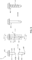
Fig. 3 is a block diagram showing the operations of a first preferred embodiment of this invention in sequential order; -
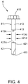
Fig. 4 is a schematic view showing the front section and the rear section; and -
Fig. 5 is a schematic view in accordance with the first preferred embodiment of this invention. - Referring to
Figs. 3 to 5 , awelding method 3 for manufacturing abi-compositional screw 4B of a first preferred embodiment of this invention includes a preparingoperation 31, awelding operation 32, and a formingoperation 33. The preparingoperation 31 prepares tworaw blanks 4 which are provided with different materials and processes the tworaw blanks 4 respectively to form afront section 41 and arear section 42, both of which are provided with smooth peripheral faces. Thefront section 41 has ahead 411, ashank 412 extending outwards from thehead 411, and afront end 413 with afront welding surface 413A formed on thefront section 41 opposite to thehead 411. Therear section 42 has arear end 421 with arear welding surface 421A formed on an end of therear section 42 and adrill end 422 formed on another end of therear section 42 opposite to therear end 421. In this preferred embodiment, both of thefront welding surface 413A and therear welding surface 421A are formed in a flat surface. Meanwhile, anouter diameter 413d of thefront end 413 is equal to anouter diameter 421d of therear end 421, thereby providing a smooth peripheral face of the bi-compositional blank 4A thereafter and an equal circumference (not shown) from theshank 412 to therear end 421. Further, thefront section 41 can be made of a corrosion-resisting material such as stainless steel. On the other hand, therear section 42 can be made of a material with higher hardness such as martensite or hardened materials. - Referring to
Fig. 3 andFig. 5 , after the preparingoperation 31, thewelding operation 32 prepares awelding device 5 and apositioning device 6 disposed below thewelding device 5, then position thefront section 41 and therear section 42 on thepositioning device 6 to allow thefront welding surface 413A and therear welding surface 421A to contact closely along an axis R and meet at a joint C2, and thence rotates thefront section 41 and therear section 42 in the same rotational direction driven by thepositioning device 6 and simultaneously welds thefront end 413 and therear end 421 at the joint C2 in a circumferential direction executed by thewelding device 5 which is disposed above the joint C2 where thefront end 413 and therear end 421 meet, thereby integrating thefront section 41 and therear section 42 to provide a bi-compositional blank 4A. Comparing with the robbing procedure of theconventional welding operation 12, thewelding operation 32 of this invention is executed by direct heating without applying additional solder, thewelding operation 32 can prevent air and pores from generating inside the joint C2 and prevents waste from being projected out of the joint C2 effectively. Thus, no additional trimming procedure is required in thewelding method 3 before executing the formingoperation 33. After thewelding operation 32, the formingoperation 33 rolls a plurality ofthreads 41 on the bi-compositional blank 4A via a threading machine (not shown) to form abi-compositional screw 4B. Thedrill end 422 can be processed into a drilling tail via a tail forming machine (not shown) according to needs. Hence, a succession of theoperations bi-compositional screw 4B, simplifies the processing procedures effectively, reduces the processing costs, and ensures the preferable processing quality. - To sum up, the welding method of this invention includes the preparing operation, the welding operation and the forming operation. The preparing operation prepares and processes two raw blanks provided with different materials into the front section and rear section respectively. The welding operation circumferentially welds the front and rear sections which are placed in the same axis at the joint by the welding device during the rotation of the front and rear sections in the same rotational direction driven by the positioning device, thereby combining the front and rear sections into the bi-compositional blank. The forming operation forms a plurality of threads on the bi-compositional blank to produce the bi-compositional screw, thereby preventing the generation of air and pores inside the joint, avoiding causing additional waste extruded out of the joint, simplifying the processing procedures, reducing the processing costs, and ensuring the preferable processing quality.
- While the embodiments of this invention are shown and described, it is understood that further variations and modifications may be made without departing from the scope of this invention.
Claims (4)
- A welding method (3) for manufacturing a bi-compositional screw (4B) comprising:a preparing operation (31) which includes preparing two raw blanks made of different materials, said two raw blanks being processed respectively to form a front section (41) and a rear section (42) each provided with a smooth peripheral face, wherein said front section (41) has a head (411), a shank (412) extending outwards from said head (411), and a front end (413) with a front welding surface (413A) formed opposite to said head (411), said rear section (42) having a rear end (421) with a rear welding surface (421A) facing said front welding surface (413A) and a drill end (422) formed opposite to said rear end (421), an outer diameter (413d) of said front end (413) being equal to an outer diameter (421d) of said rear end (421);a welding operation (32) which includes equipping a welding device (5) and a positioning device (6) located below said welding device (5), placing said front section (41) and said rear section (42) on said positioning device (6) in position along a same axis (R) so that said front welding surface (413A) of said front end (413) and said rear welding surface (421A) of said rear end (421) are in close contact at a joint (C2), then rotating said front section (41) and said rear section (42) in a same rotational direction driven by said positioning device (6), and thence welding said front end (413) and said rear end (421) together at said joint (C2) in a circumferential direction by said welding device (5) during the rotation of said front section (41) and said rear section (42) so that said front section (41) and said rear section (42) are united to attain a bi-compositional blank (4A); anda forming operation (33) which includes rolling a plurality of threads (41) on said bi-compositional blank (4A) to form a bi-compositional screw (4B).
- The welding method (3) according to claim 1, wherein said welding operation (32) heats directly without adding additional solder.
- The welding method (3) according to claim 1, wherein in said welding operation (32), said joint (C2) where said front end (413) and said rear end (421) meet is circumferentially welded by said welding device (5) to prevent waste from being extruded out of said joint (C2) after welding.
- The welding method (3) according to claim 1, wherein in said preparing operation (31), both of said front welding surface (413A) and said rear welding surface (421A) are formed in a flat surface.
Priority Applications (1)
| Application Number | Priority Date | Filing Date | Title |
|---|---|---|---|
| EP18248141.6A EP3674028A1 (en) | 2018-12-28 | 2018-12-28 | Welding method for manufacturing a bi-compositional screw |
Applications Claiming Priority (1)
| Application Number | Priority Date | Filing Date | Title |
|---|---|---|---|
| EP18248141.6A EP3674028A1 (en) | 2018-12-28 | 2018-12-28 | Welding method for manufacturing a bi-compositional screw |
Publications (1)
| Publication Number | Publication Date |
|---|---|
| EP3674028A1 true EP3674028A1 (en) | 2020-07-01 |
Family
ID=65011797
Family Applications (1)
| Application Number | Title | Priority Date | Filing Date |
|---|---|---|---|
| EP18248141.6A Pending EP3674028A1 (en) | 2018-12-28 | 2018-12-28 | Welding method for manufacturing a bi-compositional screw |
Country Status (1)
| Country | Link |
|---|---|
| EP (1) | EP3674028A1 (en) |
Cited By (3)
| Publication number | Priority date | Publication date | Assignee | Title |
|---|---|---|---|---|
| DE102021112643A1 (en) | 2021-05-17 | 2022-11-17 | Fischerwerke Gmbh & Co. Kg | Process for producing a bimetal screw, base body of a bimetal screw and bimetal screw |
| DE102021118219A1 (en) | 2021-07-14 | 2023-01-19 | Fischerwerke Gmbh & Co. Kg | Bimetal screw and method of manufacturing the bimetal screw |
| EP4336057A1 (en) | 2022-09-12 | 2024-03-13 | fischerwerke GmbH & Co. KG | Method for producing a bimetallic screw, base body of a bimetallic screw, and bimetallic screw |
Citations (5)
| Publication number | Priority date | Publication date | Assignee | Title |
|---|---|---|---|---|
| TW201115038A (en) * | 2009-10-28 | 2011-05-01 | Shehkai Prec Co Ltd | Method for manufacturing composite screw |
| US20160184930A1 (en) * | 2014-01-15 | 2016-06-30 | Ihi Corporation | Method of welding shaft and wheel in turbine shaft, turbine shaft, and welding device |
| US20170120369A1 (en) * | 2014-06-18 | 2017-05-04 | Ntn Corporation | Method for butt welding, butt welded joint, and outside joint member for constant velocity universal joint |
| JP6144323B2 (en) * | 2015-11-30 | 2017-06-07 | 平田ネジ株式会社 | Bimetal screw manufacturing method |
| EP3267052A1 (en) * | 2016-07-08 | 2018-01-10 | HILTI Aktiengesellschaft | Screw and method for its production |
-
2018
- 2018-12-28 EP EP18248141.6A patent/EP3674028A1/en active Pending
Patent Citations (5)
| Publication number | Priority date | Publication date | Assignee | Title |
|---|---|---|---|---|
| TW201115038A (en) * | 2009-10-28 | 2011-05-01 | Shehkai Prec Co Ltd | Method for manufacturing composite screw |
| US20160184930A1 (en) * | 2014-01-15 | 2016-06-30 | Ihi Corporation | Method of welding shaft and wheel in turbine shaft, turbine shaft, and welding device |
| US20170120369A1 (en) * | 2014-06-18 | 2017-05-04 | Ntn Corporation | Method for butt welding, butt welded joint, and outside joint member for constant velocity universal joint |
| JP6144323B2 (en) * | 2015-11-30 | 2017-06-07 | 平田ネジ株式会社 | Bimetal screw manufacturing method |
| EP3267052A1 (en) * | 2016-07-08 | 2018-01-10 | HILTI Aktiengesellschaft | Screw and method for its production |
Cited By (5)
| Publication number | Priority date | Publication date | Assignee | Title |
|---|---|---|---|---|
| DE102021112643A1 (en) | 2021-05-17 | 2022-11-17 | Fischerwerke Gmbh & Co. Kg | Process for producing a bimetal screw, base body of a bimetal screw and bimetal screw |
| DE102021118219A1 (en) | 2021-07-14 | 2023-01-19 | Fischerwerke Gmbh & Co. Kg | Bimetal screw and method of manufacturing the bimetal screw |
| WO2023285166A1 (en) | 2021-07-14 | 2023-01-19 | Fischerwerke Gmbh & Co. Kg | Process for manufacturing a bimetallic screw, and accordingly manufactured bimetallic screw |
| EP4336057A1 (en) | 2022-09-12 | 2024-03-13 | fischerwerke GmbH & Co. KG | Method for producing a bimetallic screw, base body of a bimetallic screw, and bimetallic screw |
| DE102022123111A1 (en) | 2022-09-12 | 2024-03-14 | Fischerwerke Gmbh & Co. Kg | Method for producing a bimetal screw, base body of a bimetal screw, and bimetal screw |
Similar Documents
| Publication | Publication Date | Title |
|---|---|---|
| EP3674028A1 (en) | Welding method for manufacturing a bi-compositional screw | |
| CN105127668B (en) | A kind of multi-party station ultrasonic wave roll processing device | |
| EP2987583B1 (en) | Rotary friction welding of tubular workpieces | |
| JP2821553B2 (en) | Method and apparatus for separating tubular workpieces into individual rings continuously and without cutting chips | |
| US8696477B2 (en) | Method for manufacturing a thread-forming screw | |
| JP2007125623A (en) | Screw forming method, screw forming device and screw forming tool | |
| JP2013010142A (en) | Method for forming desired non-planar configuration by friction stir forming tool, and method and apparatus for forming workpiece to desired non-planar configuration | |
| US20070172325A1 (en) | Forstner drill bit | |
| US10507533B2 (en) | Drill | |
| US2991551A (en) | Method and apparatus for forming holes in pipes | |
| CN105728964A (en) | Roller build-up welding technology | |
| US20200206848A1 (en) | Welding method for manufacturing a bi-compositional screw | |
| CN102713352A (en) | Method for manufacturing variator part of continuously variable transmission and chuck device for variator part manufacture | |
| JP6320855B2 (en) | Method for manufacturing outer joint member of constant velocity universal joint and outer joint member | |
| CN109312771A (en) | Screw and manufacturing method | |
| EP1923151B1 (en) | Method of manufacturing a bi-metal screw | |
| US11498159B2 (en) | Welding mechanism for manufacturing a bi-compositional screw | |
| TWI716785B (en) | Composite screw welding method | |
| CN110860783B (en) | Device for improving axial bearing capacity of main shaft of friction stir welding equipment | |
| US6334349B1 (en) | Method for the manufacturing of a shaft with a larger diameter flange | |
| US10968738B1 (en) | Remanufactured conical bit | |
| RU2247639C1 (en) | Method for friction welding of aluminum alloy butt joints | |
| CN109986225B (en) | Welding method of composite screw | |
| RU2404885C1 (en) | Method of welding tube face hole | |
| US4989377A (en) | Apparatus for internal grinding |
Legal Events
| Date | Code | Title | Description |
|---|---|---|---|
| PUAI | Public reference made under article 153(3) epc to a published international application that has entered the european phase |
Free format text: ORIGINAL CODE: 0009012 |
|
| STAA | Information on the status of an ep patent application or granted ep patent |
Free format text: STATUS: THE APPLICATION HAS BEEN PUBLISHED |
|
| AK | Designated contracting states |
Kind code of ref document: A1 Designated state(s): AL AT BE BG CH CY CZ DE DK EE ES FI FR GB GR HR HU IE IS IT LI LT LU LV MC MK MT NL NO PL PT RO RS SE SI SK SM TR |
|
| AX | Request for extension of the european patent |
Extension state: BA ME |
|
| STAA | Information on the status of an ep patent application or granted ep patent |
Free format text: STATUS: REQUEST FOR EXAMINATION WAS MADE |
|
| 17P | Request for examination filed |
Effective date: 20201019 |
|
| RBV | Designated contracting states (corrected) |
Designated state(s): AL AT BE BG CH CY CZ DE DK EE ES FI FR GB GR HR HU IE IS IT LI LT LU LV MC MK MT NL NO PL PT RO RS SE SI SK SM TR |
|
| STAA | Information on the status of an ep patent application or granted ep patent |
Free format text: STATUS: EXAMINATION IS IN PROGRESS |
|
| 17Q | First examination report despatched |
Effective date: 20220728 |