EP3673852B1 - Steuerung einer bipolaren ablation in mehrkanaligen hf-ablationsvorrichtungen - Google Patents
Steuerung einer bipolaren ablation in mehrkanaligen hf-ablationsvorrichtungen Download PDFInfo
- Publication number
- EP3673852B1 EP3673852B1 EP19220185.3A EP19220185A EP3673852B1 EP 3673852 B1 EP3673852 B1 EP 3673852B1 EP 19220185 A EP19220185 A EP 19220185A EP 3673852 B1 EP3673852 B1 EP 3673852B1
- Authority
- EP
- European Patent Office
- Prior art keywords
- ablation
- signal
- probe
- signals
- electrodes
- Prior art date
- Legal status (The legal status is an assumption and is not a legal conclusion. Google has not performed a legal analysis and makes no representation as to the accuracy of the status listed.)
- Active
Links
Images


Classifications
-
- A—HUMAN NECESSITIES
- A61—MEDICAL OR VETERINARY SCIENCE; HYGIENE
- A61B—DIAGNOSIS; SURGERY; IDENTIFICATION
- A61B18/00—Surgical instruments, devices or methods for transferring non-mechanical forms of energy to or from the body
- A61B18/04—Surgical instruments, devices or methods for transferring non-mechanical forms of energy to or from the body by heating
- A61B18/12—Surgical instruments, devices or methods for transferring non-mechanical forms of energy to or from the body by heating by passing a current through the tissue to be heated, e.g. high-frequency current
- A61B18/1206—Generators therefor
-
- A—HUMAN NECESSITIES
- A61—MEDICAL OR VETERINARY SCIENCE; HYGIENE
- A61B—DIAGNOSIS; SURGERY; IDENTIFICATION
- A61B18/00—Surgical instruments, devices or methods for transferring non-mechanical forms of energy to or from the body
- A61B18/04—Surgical instruments, devices or methods for transferring non-mechanical forms of energy to or from the body by heating
- A61B18/12—Surgical instruments, devices or methods for transferring non-mechanical forms of energy to or from the body by heating by passing a current through the tissue to be heated, e.g. high-frequency current
- A61B18/14—Probes or electrodes therefor
- A61B18/1492—Probes or electrodes therefor having a flexible, catheter-like structure, e.g. for heart ablation
-
- A—HUMAN NECESSITIES
- A61—MEDICAL OR VETERINARY SCIENCE; HYGIENE
- A61B—DIAGNOSIS; SURGERY; IDENTIFICATION
- A61B18/00—Surgical instruments, devices or methods for transferring non-mechanical forms of energy to or from the body
- A61B18/04—Surgical instruments, devices or methods for transferring non-mechanical forms of energy to or from the body by heating
- A61B18/12—Surgical instruments, devices or methods for transferring non-mechanical forms of energy to or from the body by heating by passing a current through the tissue to be heated, e.g. high-frequency current
- A61B18/14—Probes or electrodes therefor
- A61B18/16—Indifferent or passive electrodes for grounding
-
- A—HUMAN NECESSITIES
- A61—MEDICAL OR VETERINARY SCIENCE; HYGIENE
- A61B—DIAGNOSIS; SURGERY; IDENTIFICATION
- A61B18/00—Surgical instruments, devices or methods for transferring non-mechanical forms of energy to or from the body
- A61B2018/00315—Surgical instruments, devices or methods for transferring non-mechanical forms of energy to or from the body for treatment of particular body parts
- A61B2018/00345—Vascular system
- A61B2018/00351—Heart
-
- A—HUMAN NECESSITIES
- A61—MEDICAL OR VETERINARY SCIENCE; HYGIENE
- A61B—DIAGNOSIS; SURGERY; IDENTIFICATION
- A61B18/00—Surgical instruments, devices or methods for transferring non-mechanical forms of energy to or from the body
- A61B2018/00571—Surgical instruments, devices or methods for transferring non-mechanical forms of energy to or from the body for achieving a particular surgical effect
- A61B2018/00577—Ablation
-
- A—HUMAN NECESSITIES
- A61—MEDICAL OR VETERINARY SCIENCE; HYGIENE
- A61B—DIAGNOSIS; SURGERY; IDENTIFICATION
- A61B18/00—Surgical instruments, devices or methods for transferring non-mechanical forms of energy to or from the body
- A61B2018/00636—Sensing and controlling the application of energy
- A61B2018/00696—Controlled or regulated parameters
- A61B2018/00702—Power or energy
-
- A—HUMAN NECESSITIES
- A61—MEDICAL OR VETERINARY SCIENCE; HYGIENE
- A61B—DIAGNOSIS; SURGERY; IDENTIFICATION
- A61B18/00—Surgical instruments, devices or methods for transferring non-mechanical forms of energy to or from the body
- A61B2018/00636—Sensing and controlling the application of energy
- A61B2018/00696—Controlled or regulated parameters
- A61B2018/0072—Current
-
- A—HUMAN NECESSITIES
- A61—MEDICAL OR VETERINARY SCIENCE; HYGIENE
- A61B—DIAGNOSIS; SURGERY; IDENTIFICATION
- A61B18/00—Surgical instruments, devices or methods for transferring non-mechanical forms of energy to or from the body
- A61B2018/00636—Sensing and controlling the application of energy
- A61B2018/00696—Controlled or regulated parameters
- A61B2018/0075—Phase
-
- A—HUMAN NECESSITIES
- A61—MEDICAL OR VETERINARY SCIENCE; HYGIENE
- A61B—DIAGNOSIS; SURGERY; IDENTIFICATION
- A61B18/00—Surgical instruments, devices or methods for transferring non-mechanical forms of energy to or from the body
- A61B2018/00636—Sensing and controlling the application of energy
- A61B2018/00696—Controlled or regulated parameters
- A61B2018/00767—Voltage
-
- A—HUMAN NECESSITIES
- A61—MEDICAL OR VETERINARY SCIENCE; HYGIENE
- A61B—DIAGNOSIS; SURGERY; IDENTIFICATION
- A61B18/00—Surgical instruments, devices or methods for transferring non-mechanical forms of energy to or from the body
- A61B2018/00636—Sensing and controlling the application of energy
- A61B2018/00773—Sensed parameters
- A61B2018/00791—Temperature
-
- A—HUMAN NECESSITIES
- A61—MEDICAL OR VETERINARY SCIENCE; HYGIENE
- A61B—DIAGNOSIS; SURGERY; IDENTIFICATION
- A61B18/00—Surgical instruments, devices or methods for transferring non-mechanical forms of energy to or from the body
- A61B2018/00636—Sensing and controlling the application of energy
- A61B2018/00773—Sensed parameters
- A61B2018/00845—Frequency
-
- A—HUMAN NECESSITIES
- A61—MEDICAL OR VETERINARY SCIENCE; HYGIENE
- A61B—DIAGNOSIS; SURGERY; IDENTIFICATION
- A61B18/00—Surgical instruments, devices or methods for transferring non-mechanical forms of energy to or from the body
- A61B2018/00636—Sensing and controlling the application of energy
- A61B2018/00773—Sensed parameters
- A61B2018/00875—Resistance or impedance
-
- A—HUMAN NECESSITIES
- A61—MEDICAL OR VETERINARY SCIENCE; HYGIENE
- A61B—DIAGNOSIS; SURGERY; IDENTIFICATION
- A61B18/00—Surgical instruments, devices or methods for transferring non-mechanical forms of energy to or from the body
- A61B18/04—Surgical instruments, devices or methods for transferring non-mechanical forms of energy to or from the body by heating
- A61B18/12—Surgical instruments, devices or methods for transferring non-mechanical forms of energy to or from the body by heating by passing a current through the tissue to be heated, e.g. high-frequency current
- A61B18/1206—Generators therefor
- A61B2018/1246—Generators therefor characterised by the output polarity
- A61B2018/1253—Generators therefor characterised by the output polarity monopolar
-
- A—HUMAN NECESSITIES
- A61—MEDICAL OR VETERINARY SCIENCE; HYGIENE
- A61B—DIAGNOSIS; SURGERY; IDENTIFICATION
- A61B18/00—Surgical instruments, devices or methods for transferring non-mechanical forms of energy to or from the body
- A61B18/04—Surgical instruments, devices or methods for transferring non-mechanical forms of energy to or from the body by heating
- A61B18/12—Surgical instruments, devices or methods for transferring non-mechanical forms of energy to or from the body by heating by passing a current through the tissue to be heated, e.g. high-frequency current
- A61B18/1206—Generators therefor
- A61B2018/1246—Generators therefor characterised by the output polarity
- A61B2018/126—Generators therefor characterised by the output polarity bipolar
-
- A—HUMAN NECESSITIES
- A61—MEDICAL OR VETERINARY SCIENCE; HYGIENE
- A61B—DIAGNOSIS; SURGERY; IDENTIFICATION
- A61B18/00—Surgical instruments, devices or methods for transferring non-mechanical forms of energy to or from the body
- A61B18/04—Surgical instruments, devices or methods for transferring non-mechanical forms of energy to or from the body by heating
- A61B18/12—Surgical instruments, devices or methods for transferring non-mechanical forms of energy to or from the body by heating by passing a current through the tissue to be heated, e.g. high-frequency current
- A61B18/1206—Generators therefor
- A61B2018/1273—Generators therefor including multiple generators in one device
-
- A—HUMAN NECESSITIES
- A61—MEDICAL OR VETERINARY SCIENCE; HYGIENE
- A61B—DIAGNOSIS; SURGERY; IDENTIFICATION
- A61B18/00—Surgical instruments, devices or methods for transferring non-mechanical forms of energy to or from the body
- A61B18/04—Surgical instruments, devices or methods for transferring non-mechanical forms of energy to or from the body by heating
- A61B18/12—Surgical instruments, devices or methods for transferring non-mechanical forms of energy to or from the body by heating by passing a current through the tissue to be heated, e.g. high-frequency current
- A61B18/1206—Generators therefor
- A61B2018/128—Generators therefor generating two or more frequencies
-
- A—HUMAN NECESSITIES
- A61—MEDICAL OR VETERINARY SCIENCE; HYGIENE
- A61B—DIAGNOSIS; SURGERY; IDENTIFICATION
- A61B18/00—Surgical instruments, devices or methods for transferring non-mechanical forms of energy to or from the body
- A61B18/04—Surgical instruments, devices or methods for transferring non-mechanical forms of energy to or from the body by heating
- A61B18/12—Surgical instruments, devices or methods for transferring non-mechanical forms of energy to or from the body by heating by passing a current through the tissue to be heated, e.g. high-frequency current
- A61B18/14—Probes or electrodes therefor
- A61B2018/1467—Probes or electrodes therefor using more than two electrodes on a single probe
Definitions
- the present invention relates generally to therapeutic medical devices, and particularly to radiofrequency (RF) ablation devices and their manufacturing.
- RF radiofrequency
- United States Patent 5,383,917 describes multi-phase RF ablation employing a two-dimensional or three-dimensional electrode array that produces a multitude of currents paths on the surface of the ablation zone. This results in a uniform lesion with a size defined by the span of the electrode array.
- An orthogonal electrode catheter array suitable for cardiac ablation is used in conjunction with a two-phase RF power source to produce uniform square-shaped lesions of size 1.2 cm 2 . Lesions of larger size are created by successive adjacent placement of the square-shaped lesions.
- a temperature sensor at the electrode tip allows monitoring of ablation temperature and regulation of thereof to minimize the electrode tips from being fouled by coagulum.
- United States Patent Application Publication 2008/0281322 describes a radio frequency tissue ablation system with a radio frequency generator.
- the generator comprises a radio frequency source, at least four independently controllable radio frequency outputs, a user interface and a controller configured to delivery radio frequency energy from the radio frequency source to the radio frequency outputs in one of at least two different output configurations in response to a configuration selection made through the user.
- United States Patent Application Publication 2015/0272655 describes a system and method for preventing unintended tissue damage from the delivery of unintended bipolar radiofrequency energy.
- the system may include a multi-electrode ablation device and an RF delivery unit.
- the RF delivery unit may transmit unipolar energy to the plurality of electrodes, the energy being in phase, with all electrodes delivering the same voltage and being activated at the same time to deliver no bipolar energy. Additionally or alternatively, the RF delivery unit may transmit bipolar energy to the electrodes.
- voltage differences between each pair of adjacent electrodes may be monitored and the level of bipolar energy being delivered may be calculated.
- the voltage of energy delivered to at least one electrode in each adjacent electrode pair may be adjusted if the amount of delivered bipolar energy exceeds a safety threshold.
- WO2019159036A1 discloses multi-channel RF ablation.
- a plurality of control-signal generators are configured to generate respective control signals having respective control-signal amplitudes and different respective control-signal frequencies, and a plurality of signal adders are configured to produce respective composite signals for application to a subject, by adding the control signals to respective ablation signals having respective ablation-signal amplitudes.
- US2012116387A1 discloses multichannel ablation with frequency differentiation.
- An energy generator is configured to supply first ablation power modulated at a first frequency and second ablation power modulated at a second frequency different from the first frequency.
- the apparatus also includes a probe, having at least one electrode coupled to receive the first and second ablation powers simultaneously and to dissipate the first and second ablation powers in body tissue in contact with the at least one electrode.
- US2009171345A1 discloses a system and method for measurement of impedance using a catheter, such as an ablation catheter.
- US2007255269A1 discloses a multi-channel radio frequency generator for high-frequency thermal treatment.
- EP1112720A1 discloses a device for treating biological tissues with high frequency currents.
- Embodiments of the present invention that are described hereinbelow provide improved RF ablation devices.
- the invention is defined in claim 1.
- an ablation system including multiple electrodes configured to contact body tissue of a patient, including two or more ablation electrodes for contacting respective locations in a target organ and a return electrode.
- a signal-generating unit includes multiple signal generators, which are configured to apply respective composite signals to respective ones of the ablation electrodes.
- the composite signals include multiple, respective signal components, including respective ablation signals, having different, respective ablation-signal amplitudes and phases at a common ablation-signal frequency, and respective probe signals having respective probe-signal amplitudes and different respective probe-signal frequencies.
- a processor is coupled to measure the probe signals received by each of the multiple electrodes, and responsively to the measured probe signals, to control the ablation-signal amplitudes and phases.
- each of the multiple signal generators includes an ablation-signal generator and a probe-signal generator.
- Each of the multiple signal generators includes a signal adder, coupled to the respective ablation-signal generator and the respective probe-signal generator, and the signal adder is configured to produce a respective composite signal by adding the respective probe signal to the respective ablation signal.
- the processor is configured to compute from the measured probe signals an admittance matrix between the multiple electrodes and to apply the admittance matrix in setting the ablation-signal amplitudes and phases.
- the processor is configured to set the ablation-signal amplitudes and phases so as to cause respective unipolar and bipolar ablation currents to emanate from the electrodes into the body tissue.
- the processor is configured to compute the respective amplitudes and phases of the ablation signals responsively to preset unipolar and bipolar ablation currents and the admittance matrix, wherein applying the computed ablation signals to the electrodes causes the preset unipolar and bipolar ablation currents to emanate from the electrodes.
- the processor is configured to minimize a difference between the respective preset unipolar and bipolar ablation currents and the emanating unipolar and bipolar ablation currents. Additionally or alternatively, the processor may adjust the phases so as to control a ratio between the unipolar and bipolar ablation currents.
- the processor is configured to monitor changes in the probe signals during an ablation procedure, and to update the admittance matrix during the ablation procedure responsively to the changes.
- a ratio between the probe-signal amplitudes and the ablation-signal amplitudes is less than 1:15. Additionally or alternatively, the probe-signal frequencies differ from one another and from the ablation-signal frequency by at least 500 Hz.
- the multiple electrodes are disposed on a catheter, which is configured to contact a heart of the patient.
- a method for ablation which includes placing multiple electrodes in contact with body tissue of a patient, including two or more ablation electrodes contacting respective locations in a target organ and a return electrode. Respective composite signals are applied to respective ones of the ablation electrodes, the composite signals including multiple, respective signal components, including respective ablation signals, having different, respective ablation-signal amplitudes and phases at a common ablation-signal frequency, and respective probe signals having different respective probe-signal frequencies.
- the probe signals received by each of the multiple electrodes are measured, and the ablation-signal amplitudes and phases are controlled responsively to the measured probe signals.
- RF ablation of tissue of a patient requires a minimum of two electrodes, typically an ablation electrode internal to the patient, and a return electrode which may be on the patient's skin.
- an ablation electrode internal to the patient
- a return electrode which may be on the patient's skin.
- This type of energy transfer is termed unipolar energy transfer, and the ablating current is termed unipolar ablating current.
- a unipolar ablating current has its ablating effect concentrated in the tissue, between the ablation electrode and the return electrode.
- bipolar energy transfer energy transfer between internal electrodes
- bipolar ablating current energy transfer between internal electrodes
- the ablating effect of a bipolar ablating current is typically concentrated in the superficial tissue between the internal electrodes.
- the division of the ablating current between unipolar and bipolar currents may be used for controlling the spatial distribution of the ablation in the tissue.
- some of the ablating current may travel along unwanted paths.
- two internal electrodes may be energized so as to provide intended bipolar energy transfer, but their activation typically also provides unipolar energy transfer, which is unintended.
- the current from a given electrode may consist of intended unipolar ablating current, intended bipolar ablating current flowing to a certain internal electrode, and unintended bipolar ablating current flowing to another internal electrode.
- Unipolar and bipolar ablation currents may be controlled by time-division multiplexing (TDM), wherein only one ablation electrode or a small subset of the electrodes are energized at a time.
- TDM time-division multiplexing
- ECG electrocardiogram
- Embodiments of the present invention that are described herein address these problems by incorporating into the network of electrodes and tissue identifiable probing signals, computing an admittance matrix for the network based on the probing signals, and computing the amplitudes and phases for the ablating voltages and currents of each electrode so as to achieve the required unipolar and bipolar ablating currents.
- the multiple ablation electrodes contacting the patient's tissue are energized by an electrode circuit similar to that used in United States Patent Application document 15/898,052, filed on February 15, 2018 , and published as US 2019/0247108 , which is further detailed below.
- the electrode circuit measures the current traversing each internal electrode in a multi-electrode system by driving a low-amplitude probe current through the electrode, either by itself or added to each high-amplitude ablation current.
- the probe current for each electrode has a different frequency unique to that electrode, which enables a measurement and identification of the probe current flowing through all electrodes, as well as the corresponding voltages on all electrodes.
- each composite signal flows through a respective controlled gain stage, which is adjusted for feeding a predetermined ablation signal power through the respective electrode.
- the concept of using the phase of the ablation signals for controlling the relative amounts of unipolar and bipolar currents may be illustrated by a system with two internal electrodes (and a third return electrode): If the ablation voltages of the two internal electrodes have the same amplitude and frequency but are in antiphase, there is substantially no unipolar current, and 100% bipolar current. Alternatively, if the voltages of the two electrodes are in phase, then there is substantially no bipolar current, and 100% unipolar current. In general, the ratio between unipolar and bipolar ablation currents can be adjusted by adjusting the phase of the voltage at each electrode. The admittance matrix described above can be used in finding the appropriate adjustments.
- the probe currents and voltages are continuously monitored by a processor, which computes and updates the admittance matrix between all the electrodes.
- Fig. 1 is a schematic pictorial illustration of a multi-channel ablation system 20 and procedure, in accordance with embodiments of the invention.
- a physician 27 is performing a multi-channel cardiac ablation procedure using ablation system 20.
- Physician 27 is performing the procedure on a subject 25, using an ablation catheter 23 whose distal end 36 comprises multiple ablation electrodes 44.
- a signal-generating unit (SIG GEN) 22 generates multiple signals 34, which are referred to herein as “composite signals” or “composite ablation signals,” as explained below with reference to Fig. 3 .
- a “signal” comprises both a current and a voltage; when necessary, a specific reference is made to either current or voltage.
- Signals 34 are carried through catheter 23, over different respective channels, to ablation electrodes 44, such that each electrode applies a different respective one of signals 34 to tissue 33 of subject 25.
- Ablation system 20 further comprises a processor (PROC) 24.
- Processor 24 is configured to receive from physician 27 (or any other user), prior to and/or during the ablation procedure, setup parameters 38 for the procedure. For example, using one or more suitable input devices such as a keyboard, mouse, or touch screen, physician 27 selects one of two modes of ablation: (i) a current mode, or (ii) a power mode. In the current mode, physician 27 either sets the total ablation current for each electrode 44 or sets separately the desired levels for the unipolar current and the bipolar currents for the electrode.
- physician 27 either sets the total ablation power for each electrode 44 or sets separately the desired levels for unipolar power and the bipolar powers for the electrode, wherein the ablation power is computed from the voltage and current of the ablation signal, taking into account any phase shift between the two. While the description herein uses these two modes, it will be understood that the modes are example modes of ablation, and those having ordinary skill in the art will be able to adapt the description, mutatis mutandis, for other modes of ablation.
- Physician 27 may also input, using the above mentioned input devices, for each ablation signal 34 (either for the total signal or separately for the unipolar and bipolar signals), a maximum power, a maximum current amplitude, a maximum voltage amplitude, a duration of the signal, and/or any other relevant parameters. (Typically, but not necessarily, these parameters are the same across all of the signals.)
- processor 24 In response to receiving setup parameters 38, processor 24 communicates with signal-generating unit 22, so that the signal-generating unit generates signals 34 in accordance with the setup parameters. Additionally, the processor may display the setup parameters on a display 26 (which may comprise the aforementioned touch screen).
- Processor 24 may be further configured to track the respective positions of ablation electrodes 44 during the procedure, using any suitable tracking technique.
- distal end 36 may comprise one or more electromagnetic position sensors (not shown), which, in the presence of an external magnetic field generated by one or more magnetic-field generators 42, output signals that vary with the positions of the sensors. Based on these signals, the processor may ascertain the positions of the electrodes.
- processor 24 may ascertain the respective impedances between the electrode and multiple external electrodes 49 coupled to subject 25 at various different locations, and then compute the ratios between these impedances, these ratios being indicative of the electrode's location.
- the processor may use both electromagnetic tracking and impedance-based tracking, as described, for example, in US Patent 8,456,182 .
- the processor ascertains which of ablation electrodes 44 are in contact with the subject's tissue, and causes those electrodes, but not the other electrodes, to deliver signals 34 to the tissue.
- the processor may select a subset of channels leading to those electrodes that are in contact with the tissue, and then cause signals 34 to be passed over the selected subset of channels, but not over the other channels.
- the processor displays, on display 26, a relevant image 40 of the subject's anatomy, annotated, for example, to show the current position and orientation of distal end 36.
- the processor may track the temperature and/or impedance of tissue 33, and control signal-generating unit 22 responsively thereto.
- the processor may perform any other relevant function for controlling, or otherwise facilitating the performance of, the procedure.
- Processor 24, and signal-generating unit 22, typically reside within a console 28, and both the processor and the signal-generating unit may each comprise one or several units.
- Catheter 23 is connected to console 28 via an electrical interface 35, such as a port or socket. Signals 34 are thus carried to distal end 36 via interface 35. Similarly, signals for tracking the position of distal end 36, and/or signals for tracking the temperature and/or impedance of the tissue, may be received by processor 24 via interface 35.
- Processor 24 may typically comprise both analog and digital elements. Thus, processor 24 may comprise multiple analog-to-digital converters (ADCs) for receiving analog signals from signal-generating unit 22. Processor 24 may further comprise multiple digital-to-analog converters (DACs) for transmitting analog control signals to signal-generating unit 22. Alternatively, these control signals may be transmitted in digital form, provided that signal-generating unit 22 is configured to receive digital control signals. Processor 24 typically comprises digital filters for extracting signals at given frequencies from the received signals. Some or all of these components may be included in a field-programmable gate array (FPGA), such as a Cyclone Family FPGA by Intel of Santa Clara, California, USA.
- FPGA field-programmable gate array
- processor 24 may comprise a programmed digital computing device comprising at least a central processing unit (CPU) and random access memory (RAM).
- Program code including software programs, and/or data are loaded into the RAM for execution and processing by the CPU.
- the program code and/or data may be downloaded to the processor in electronic form, over a network, for example.
- the program code and/or data may be provided and/or stored on non-transitory tangible media, such as magnetic, optical, or electronic memory.
- Such program code and/or data when provided to the processor, produce a machine or special-purpose computer, configured to perform the tasks described herein.
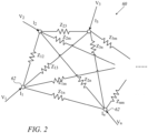
- Fig. 2 is a schematic illustration of an equivalent circuit 60 representing an ablation circuit of n-1 ablation electrodes and an external electrode ("return patch"), in accordance with an embodiment of the invention.
- Equivalent circuit 60 comprises n nodes 62, numbered from 1 to n, representing n-1 ablation electrodes 44 and one external electrode 51.
- the index m refers to a general node 62.
- a current flowing through each node 62 sees an impedance to all the other nodes due to tissue 33 between the nodes, as well as to the contact resistance between the electrode and the tissue.
- these impedances are represented as partial impedances Z ij , wherein the indices i and j refer to nodes i and j.
- the impedances Z ij have complex values in general, leading to phase differences between the currents and voltages in equivalent circuit 60.
- I i I 1 ⁇ I n
- V i V 1 ⁇ V n
- One of nodes 62 (commonly taken as return patch 51) is generally chosen to be a "ground" or reference node r at zero potential, and the corresponding column in Y may be ignored (as it is multiplied by 0 in equation (3)). The corresponding row in Y may also be ignored, as the corresponding current may always be computed by summing the currents in all other nodes.
- a modified current vector ⁇ is defined as a vector comprising the currents of all nodes except reference node r
- a modified voltage vector ⁇ is similarly defined as a vector comprising the voltages of all nodes except reference node r.
- n-1 vectors V k and I k are measured, wherein the index k assumes the values from 1 to n-1 for the frequencies, and the n-1 elements in each vector refer to n-1 nodes 62.
- These vectors are assembled into respective (n-1) ⁇ (n-1) matrices V and I .
- Equation (7) is valid for the n-1 frequencies f 1 , ... f n- 1, i.e., matrix ⁇ does not vary with these frequencies as long as they are limited to within a sufficiently narrow frequency band (to be detailed below).
- an (n-1) ⁇ 1 unit vector 1 is defined as a vector of length n-1, wherein every element of the vector is equal to 1.
- This vector is convenient for summing elements of vectors or matrices.
- 1 T ⁇ V is the sum of elements of a vector V
- 1 T ⁇ S is a sum of rows of matrix S
- 1 T ⁇ S ⁇ 1 is a sum of all elements of matrix S
- 1 ⁇ V is a vector wherein every element is V .
- ablation procedure is performed by applying ablation voltages, denoted by an ablation voltage vector V abl , between ablation electrodes 44 and external electrode 51.
- ablation voltage vector V abl are the individual ablation voltages V i for each node i.
- Vu 1 ⁇ T ⁇ Y ⁇ _ ⁇ V ⁇ abl 1 ⁇ T ⁇ Y ⁇ _ ⁇ 1 ⁇
- the element (i,j) of matrix Y U is given by equation (16) :
- Y ij U ⁇ k Y ⁇ ik ⁇ k Y ⁇ jk ⁇ m ⁇ k Y ⁇ mk
- a cost function may be defined in order to calculate the ablation currents that will yield levels of unipolar and bipolar currents that are optimally close to the desired levels.
- values for the optimization targets are typically calculated that give a minimal value to the cost function and utilized in algorithm 120.
- a target current vector for unipolar currents is written as I target U
- a target current vector for bipolar currents is written as I target B
- the parameters a and b are relative weights of the unipolar and bipolar currents
- the asterisk (*) denotes a conjugate operation
- the optimization targets are the complex-valued elements of the ablation vector V abl .
- the target vectors as well as the relative weights are typically determined by physician 27.
- Fig. 3 is a schematic circuit diagram of signal-generating unit 22, in accordance with embodiments of the invention.
- Signal-generating unit 22 in parts similar to the electrode circuit described in United States Patent Application 15/898,052 , referenced above, comprises multiple signal generators 80, configured to generate signals 34, respectively, for application to subject 25 through ablation electrodes 44, as described above with reference to Fig. 1 .
- each signal generator 80 is configured to generate a different, respective signal 34, to be passed through a corresponding electrode 44 to tissue 33 of subject 25.
- Fig. 3 refers, following the previous treatment, to an ablation catheter 23 with n-1 ablation electrodes 44, with the ablation electrodes labeled E 1 ,E 2 ,...,E n-1 , and external electrode (return patch) 51 labeled E r .
- each signal generator 80 comprises a probe-signal generator 82, configured to generate a probe signal at a unique probe-signal frequency f k , an ablation-signal generator 84, configured to generate an ablation signal at an ablation signal frequency f ABL , and a signal adder 86, configured to produce signal 34 (after gain control and amplification, as described below) by adding the generated probe signal to the generated ablation signal.
- signal 34 being a combination of a probe signal and an ablation signal, it is referred to herein as a "composite signal” or “composite ablation signal,” as noted above with reference to Fig. 1 .
- the probe signals are utilized, independently from the ablation signals, for computing and updating the admittance matrix ⁇ .
- All probe-signal generators 82 may emit their signals simultaneously, so that n-1 probe-signals at n-1 different frequencies may simultaneously be propagating within the circuit and sampled at each of the n-1 nodes.
- the ablation signals typically have a single common ablation-signal frequency f ABL .
- the index "k” refers to the k th channel of the n-1 channels, as described below.
- signal-generating unit 22 may comprise any suitable number of signal generators 80, corresponding to the number of ablation electrodes 44.
- signal-generating unit 22 may comprise from two to twenty signal generators 80.
- Fig. 3 schematically illustrates n-1 signal generators 80 forming n-1 channels, by showing both the first and n-1 st signal generator.
- the first ablation-signal generator 84 is indicated by the notation "ABL 1 ", while the n-1 st ablation-signal generator 84 is indicated by the notation "ABL n-1 ".
- the first probe-signal generator 82 is indicated by the notation "PRB 1 ", while the n-1 st probe-signal generator 82 is indicated by the notation "PRB n-1 ".
- ablation-signal generators 84 are voltage sources, wherein the output voltage of each ablation-signal generator is set by an external control signal. In an alternative embodiment the ablation signal generators are current sources, wherein the output current is set by the external control signal.
- Each ablation-signal generator 84 and probe-signal generator 82 may comprise a digital-to-analog converter, a stable analog free-running generator, or a direct digital synthesizer (DDS), such as the AD9854 DDS by Analog Devices, Inc., of Norwood, Massachusetts, USA.
- DDS direct digital synthesizer
- the smallest difference between any two of the probe-signal frequencies f k is large enough so as to inhibit the generation of problematic parasitic frequencies. For example, this difference may be greater than 500 Hz, which is the typical bandwidth of an ECG signal.
- the difference between the ablation-signal frequency and the closest probe-signal frequency i.e., the probe-signal frequency that is closest to the ablation-signal frequency, relative to the other probe-signal frequencies
- the probe-signal frequencies are typically close enough to the ablation-signal frequency so that the probe signals and ablation signals have similar frequency-related effects on tissue 33.
- the difference between any pair of successive frequencies may be between 500 and 1500 Hz.
- the difference between the ablation-signal frequency and the closest probe-signal frequency, and (ii) the difference between any pair of successive probe-signal frequencies that are both greater than or both less than the ablation-signal frequency may be between 500 and 1500 Hz.
- the probe-signal frequencies f k may consist of 486-(n-1)/2 kHz, 486-(n-1)/2+1 kHz, ... 485 kHz, 487 kHz, ... 486+(n-1)/2-1 kHz, and 486+(n-1)/2 kHz.
- Each probe-signal generator is configured to generate its probe signal such that the ratio between the amplitude of the probe signal and the amplitude of the ablation signal to which the probe signal is added is typically less than 1:15, such as less than 1:20, 1:40, 1:60, 1:80, 1:100, or 1:120, such that, by virtue of the relatively small amplitude of the probe signal, relatively little intermodulation distortion is introduced, and the contribution of the probe signals to the ablation power is negligible.
- the probe signal may have an amplitude of 1-2 V. Due to the frequency of the probe signal being similar to that of the ablation signal, the two signals see a similar admittance across the tissue of the subject, such that the ratio between the voltages of the two signals is generally the same as the ratio between the currents of the two signals.
- Signal-generating unit 22 further comprises multiple controlled gain stages 88, configured to adjust the respective amplitudes of the composite signals during the application of the composite signals to the subject.
- signal-generating unit 22 comprises one controlled gain stage 88 for each signal generator 80, such that the output from each signal adder 86 is passed to a different respective controlled gain stage.
- Fig. 3 indicates the first controlled gain stage 88 by the notation "GS 1 ", and the n-1 st controlled gain stage 88 by the notation "GS N ".
- Each controlled gain stage 88 may comprise, for example, a digital potentiometer, such as the AD5122 digital potentiometer by Analog Devices.
- signal-generating unit 22 further comprises multiple amplifiers 90, configured to amplify the adjusted signals received from controlled gain stages 88.
- the first amplifier 90 is indicated by the notation "AMP 1 "
- the n-1 st amplifier is indicated by the notation "AMP n-1 ".
- the amplified signals 34 are output to ablation electrodes 44, over multiple channels 92.
- output transformers OT 1 ,...,OT n-1 provide electrical isolation between the electrodes and signal generating unit 22.
- Signal-generating unit 22 further comprises circuitry for each channel 92, such as a voltage transformer 94 and a current transformer 96, configured to step-down the voltage and current of signal 34 to measurable levels.
- the stepped-down voltage e.g., the voltage induced across each voltage transformer 94, and indicated by notation V SD i
- the stepped-down current e.g., the current induced through each current transformer 96, and indicated by notation I SD i
- These signals are then filtered, by the digital filter of processor 24, to extract the signal components at each of the different probe signal frequencies f k .
- processor 24 calculates the voltage and current, V PRB,ik and I PRB,ik , respectively, of the probe signals from the filtered signals for channel i and for each frequency f k .
- processor 24 may measure the amplitudes of the filtered signals, and then multiply each of these amplitudes by the appropriate transformer ratio to obtain V PRB,ik and I PRB,ik .
- V PRB,ik and I PRB,ik From the measured values of V PRB,ik and I PRB,ik the elements of the admittance matrix ⁇ are calculated by processor 24, as detailed above in the section entitled "FORMALISM FOR EXTRACTING THE ADMITTANCE MATRIX ⁇ .”
- the ablation voltages V abl for producing the desired levels of unipolar and bipolar currents are calculated by processor 24, as detailed above in the section entitled "OPTIMIZATION.”
- processor 24 utilizes the admittance matrix ⁇ and the required ablation currents I i to compute updated values for the amplitudes and phases of the ablation voltages V i .
- these updated values are computed based on the required ablation powers.
- control parameters CTRL i may include, for each channel i, the following: (i) an ON/OFF command for ablation-signal generator 84 (ABL i ), (ii) an ON/OFF command for probe-signal generator 82 (PRB i ), (iii) a signal to adjust the amplitude and phase of the output of ablation-signal generator 84 (ABL i ) (either voltage output or current output, depending on whether the ablation-signal generators are voltage sources or current sources), and (iv) a signal to adjust the gain of controlled gain stage 88 (GS i ).
- Control parameters CTRL i may be communicated directly from processor 24, or via any suitable hardware or other circuitry (not shown in Fig. 3 ).
- Processor 24 may monitor additional parameters relevant for the ablation procedure. For example, processor 24 may continually (i) monitor the temperature at the interface between distal end 36 and tissue 33, (ii) responsively to this temperature, compute target ablation-signal powers, which do not exceed the maximum power specified by physician 27, and (iii) adjust the amplitudes and phases of the ablation voltages V i and currents I i and communicate the adjustments to signal-generating unit 22 via control parameters CTRL i .
- signal-generating unit 22 may comprise any other suitable circuitry, such as, for example, output transformers for impedance matching, passive bandpass and/or band-stop filters, or passive overvoltage protection devices.
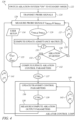
- Fig. 4 is an algorithm 120 (in the form of a flowchart) that schematically illustrates feedback control loops for controlling the ablation signals, in accordance with an embodiment of the invention.
- Algorithm 120 shows the major steps of the control loops. The main signals communicated between the steps are shown inside ovals.
- a standby step 122 ablation system 20 is turned on and goes into a standby mode.
- probe-signal generators 82 are turned on and can transmit probe signals, but no ablation signals are yet transmitted from ablation-signal generators 84.
- probe signals at frequencies f k are transmitted from probe-signal generators 82 (PRB k ).
- processor 24 measures and computes the probe signals V PRB,ik and I PRB,ik (as described above with reference to Fig. 3 ) by receiving the step-down signals V SD i and I SD i , and by separating each frequency component of the probe signals through digital filtering.
- Processor 24 further outputs the (n-1) ⁇ (n-1) probe signals (oval 129) to an admittance matrix computation step 128. At this step, processor 24 computes and updates the admittance matrix ⁇ , and outputs it (oval 131) to a query step 130. In query step 130, processor 24 checks whether physician 27 has started the ablation process. If ablation has not started, processor 24 enters a loop comprising steps 126, 128, and 130, wherein the processor keeps measuring the probe signals from the received step-down signals (oval 127) and updating the admittance matrix ⁇ . The fact that this loop runs in the absence of any ablation signals supports the use of the probe signals, independently of the ablation signals, for computing the admittance matrix ⁇ .
- query step 130 transmits the admittance matrix ⁇ (oval 133) to a control parameter computation step 132.
- the desired levels of unipolar and/or bipolar currents I target U and I target B (oval 135) are received, for example as set by physician 27 in a user setup step 134.
- Processor 24 utilizes the desired levels of unipolar and bipolar currents and the admittance matrix to compute and update the control parameters CTRL i .
- the updated control parameters (ovals 137 and 139) are transmitted to signal-generating unit 22 in a control parameter update/transmission step 136, and the amplitudes and phases of the ablation voltages V i are adjusted accordingly.
- Processor 24 again receives the step-down signals V SD i and I SD i (ovals 141 and 143) and enters two feedback loops (i) and (ii):
Landscapes
- Health & Medical Sciences (AREA)
- Surgery (AREA)
- Engineering & Computer Science (AREA)
- Life Sciences & Earth Sciences (AREA)
- Biomedical Technology (AREA)
- Molecular Biology (AREA)
- Nuclear Medicine, Radiotherapy & Molecular Imaging (AREA)
- Plasma & Fusion (AREA)
- Physics & Mathematics (AREA)
- Heart & Thoracic Surgery (AREA)
- Medical Informatics (AREA)
- Otolaryngology (AREA)
- Animal Behavior & Ethology (AREA)
- General Health & Medical Sciences (AREA)
- Public Health (AREA)
- Veterinary Medicine (AREA)
- Cardiology (AREA)
- Surgical Instruments (AREA)
Claims (12)
- Ablationssystem (20), umfassend:mehrere Elektroden, die dafür ausgelegt sind, Körpergewebe eines Patienten (25) zu kontaktieren, einschließlich zwei oder mehr Ablationselektroden (44) zum Kontaktieren jeweiliger Stellen in einem Zielorgan und einer Rückführelektrode (51);eine Signalerzeugungseinheit (22), umfassend mehrere Signalgeneratoren, die dafür ausgelegt sind, jeweilige zusammengesetzte Signale an jeweilige der Ablationselektroden anzulegen, wobei die zusammengesetzten Signale mehrere jeweilige Signalkomponenten umfassen, einschließlich jeweiliger Ablationssignale, die unterschiedliche jeweilige Ablationssignalamplituden und -phasen bei einer gemeinsamen Ablationssignalfrequenz aufweisen, und jeweiliger Sondensignale, die jeweilige Sondensignalamplituden und unterschiedliche jeweilige Sondensignalfrequenzen aufweisen; undeinen Prozessor (24), der gekoppelt ist, um die von jeder der mehreren Elektroden empfangenen Sondensignale zu messen und, als Reaktion auf die gemessenen Sondensignale, die Ablationssignalamplituden und -phasen zu steuern.
- Ablationssystem nach Anspruch 1, wobei jeder der mehreren Signalgeneratoren einen Ablationssignalgenerator (80) und einen Sondensignalgenerator (82) umfasst.
- Ablationssystem nach Anspruch 2, wobei jeder der mehreren Signalgeneratoren einen Signaladdierer (86) umfasst, der mit dem jeweiligen Ablationssignalgenerator und dem jeweiligen Sondensignalgenerator gekoppelt ist, und wobei der Signaladdierer dafür ausgelegt ist, durch Hinzufügen des jeweiligen Sondensignals zu dem jeweiligen Ablationssignal ein jeweiliges zusammengesetztes Signal zu erzeugen.
- Ablationssystem nach Anspruch 1, wobei der Prozessor dafür ausgelegt ist, aus den gemessenen Sondensignalen eine Admittanzmatrix zwischen den mehreren Elektroden zu berechnen und die Admittanzmatrix beim Einstellen der Ablationssignalamplituden und -phasen anzuwenden.
- Ablationssystem nach Anspruch 4, wobei der Prozessor dafür ausgelegt ist, die Ablationssignalamplituden und -phasen, als Reaktion auf die Admittanzmatrix, einzustellen, um zu bewirken, dass jeweilige unipolare und bipolare Ablationsströme von den Elektroden in das Körpergewebe ausströmen.
- Ablationssystem nach Anspruch 5, wobei der Prozessor dafür ausgelegt ist, die jeweiligen Amplituden und Phasen der Ablationssignale als Reaktion auf voreingestellte unipolare und bipolare Ablationsströme und die Admittanzmatrix zu berechnen, wobei das Anlegen der berechneten Ablationssignale an die Elektroden bewirkt, dass die voreingestellten unipolaren und bipolaren Ablationsströme von den Elektroden ausströmen.
- Ablationssystem nach Anspruch 6, wobei der Prozessor dafür ausgelegt ist, eine Differenz zwischen den jeweiligen voreingestellten unipolaren und bipolaren Ablationsströmen und den ausströmenden unipolaren und bipolaren Ablationsströmen zu minimieren.
- Ablationssystem nach Anspruch 5, wobei der Prozessor dafür ausgelegt ist, die Phasen anzupassen, um ein Verhältnis zwischen den unipolaren und bipolaren Ablationsströmen zu steuern.
- Ablationssystem nach Anspruch 4, wobei der Prozessor dafür ausgelegt ist, während eines Ablationsverfahrens Änderungen in den Sondensignalen zu überwachen und die Admittanzmatrix während des Ablationsverfahrens als Reaktion auf die Änderungen zu aktualisieren.
- Ablationssystem nach Anspruch 1, wobei ein Verhältnis zwischen den Sondensignalamplituden und den Ablationssignalamplituden kleiner als 1:15 ist.
- Ablationssystem nach Anspruch 1, wobei sich die Sondensignalfrequenzen untereinander und von der Ablationssignalfrequenz um mindestens 500 Hz unterscheiden.
- Ablationssystem nach Anspruch 1, wobei die mehreren Elektroden auf einem Katheter (23) angeordnet sind, der dafür ausgelegt ist, ein Herz (30) des Patienten zu kontaktieren.
Applications Claiming Priority (2)
| Application Number | Priority Date | Filing Date | Title |
|---|---|---|---|
| US201862786755P | 2018-12-31 | 2018-12-31 | |
| US16/673,851 US11712284B2 (en) | 2018-12-31 | 2019-11-04 | Controlling bipolar ablation in multi-channel RF ablation devices |
Publications (3)
| Publication Number | Publication Date |
|---|---|
| EP3673852A1 EP3673852A1 (de) | 2020-07-01 |
| EP3673852C0 EP3673852C0 (de) | 2024-06-12 |
| EP3673852B1 true EP3673852B1 (de) | 2024-06-12 |
Family
ID=69055907
Family Applications (1)
| Application Number | Title | Priority Date | Filing Date |
|---|---|---|---|
| EP19220185.3A Active EP3673852B1 (de) | 2018-12-31 | 2019-12-31 | Steuerung einer bipolaren ablation in mehrkanaligen hf-ablationsvorrichtungen |
Country Status (5)
| Country | Link |
|---|---|
| US (1) | US11712284B2 (de) |
| EP (1) | EP3673852B1 (de) |
| JP (1) | JP7330884B2 (de) |
| CN (1) | CN111493999B (de) |
| IL (1) | IL271677B2 (de) |
Families Citing this family (3)
| Publication number | Priority date | Publication date | Assignee | Title |
|---|---|---|---|---|
| US12402937B2 (en) * | 2021-03-10 | 2025-09-02 | Biosense Webster (Israel) Ltd. | Initiating IRE generation with a ramp |
| CN115429412A (zh) * | 2022-09-05 | 2022-12-06 | 苏州中荟医疗科技有限公司 | 一种消融设备及消融能量提供方法 |
| US12150702B1 (en) | 2024-06-03 | 2024-11-26 | Physcade, Inc. | Generator and catheter for tissue ablation |
Citations (3)
| Publication number | Priority date | Publication date | Assignee | Title |
|---|---|---|---|---|
| WO2000078239A2 (en) * | 1999-06-17 | 2000-12-28 | Cardiac Pacemakers, Inc. | Rf ablation apparatus and method having electrode/tissue contact assessment scheme and electrocardiogram filtering |
| US20110163770A1 (en) * | 2010-01-05 | 2011-07-07 | General Electric Company | Electrical network representation of a distributed system |
| US20150272655A1 (en) * | 2014-03-27 | 2015-10-01 | Medtronic Ablation Frontiers, Llc | Controlled rf energy in a multi-electrode catheter |
Family Cites Families (17)
| Publication number | Priority date | Publication date | Assignee | Title |
|---|---|---|---|---|
| US5383917A (en) | 1991-07-05 | 1995-01-24 | Jawahar M. Desai | Device and method for multi-phase radio-frequency ablation |
| EP1112720B1 (de) | 1999-12-29 | 2005-08-31 | Stockert, Rüdiger | Vorrichtung für die Behandlung von biologischem Gewebe mittels Hochfrequenzstrom |
| KR100739002B1 (ko) | 2006-04-28 | 2007-07-12 | (주) 태웅메디칼 | 고주파 열치료용 멀티 알에프 제너레이터 |
| US8641704B2 (en) * | 2007-05-11 | 2014-02-04 | Medtronic Ablation Frontiers Llc | Ablation therapy system and method for treating continuous atrial fibrillation |
| US10660690B2 (en) | 2007-12-28 | 2020-05-26 | St. Jude Medical, Atrial Fibrillation Division, Inc. | System and method for measurement of an impedance using a catheter such as an ablation catheter |
| US8456182B2 (en) | 2008-09-30 | 2013-06-04 | Biosense Webster, Inc. | Current localization tracker |
| US8556891B2 (en) * | 2010-03-03 | 2013-10-15 | Medtronic Ablation Frontiers Llc | Variable-output radiofrequency ablation power supply |
| US9005193B2 (en) * | 2010-11-08 | 2015-04-14 | Biosense Webster (Israel) Ltd. | Multichannel ablation with frequency differentiation |
| US9005192B2 (en) * | 2010-11-08 | 2015-04-14 | Biosense Webster (Israel) Ltd. | Simultaneous ablation by multiple electrodes |
| US9028479B2 (en) * | 2011-08-01 | 2015-05-12 | Covidien Lp | Electrosurgical apparatus with real-time RF tissue energy control |
| ES2703556T3 (es) * | 2011-10-15 | 2019-03-11 | Diros Tech Inc | Aparato para controlar con precisión el tamaño y la forma de ablaciones por radiofrecuencia |
| US9918788B2 (en) * | 2012-10-31 | 2018-03-20 | St. Jude Medical, Atrial Fibrillation Division, Inc. | Electrogram-based ablation control |
| US9519021B2 (en) * | 2013-03-11 | 2016-12-13 | Covidien Lp | Systems and methods for detecting abnormalities within a circuit of an electrosurgical generator |
| CN104901630B (zh) * | 2015-05-27 | 2018-04-17 | 复旦大学 | 实现线性消融的可调射频相位差功率放大电路 |
| WO2017192477A1 (en) * | 2016-05-02 | 2017-11-09 | Affera, Inc. | Method of inserting a catheter with an expandable tip and a system comprising a catheter, a sheath and an insertion sleeve |
| US11364075B2 (en) * | 2017-12-28 | 2022-06-21 | Cilag Gmbh International | Radio frequency energy device for delivering combined electrical signals |
| US11116563B2 (en) | 2018-02-15 | 2021-09-14 | Biosense Webster (Israel) Ltd. | Multi-channel RF ablation |
-
2019
- 2019-11-04 US US16/673,851 patent/US11712284B2/en active Active
- 2019-12-24 IL IL271677A patent/IL271677B2/en unknown
- 2019-12-27 JP JP2019237815A patent/JP7330884B2/ja active Active
- 2019-12-31 EP EP19220185.3A patent/EP3673852B1/de active Active
- 2019-12-31 CN CN201911410676.7A patent/CN111493999B/zh active Active
Patent Citations (3)
| Publication number | Priority date | Publication date | Assignee | Title |
|---|---|---|---|---|
| WO2000078239A2 (en) * | 1999-06-17 | 2000-12-28 | Cardiac Pacemakers, Inc. | Rf ablation apparatus and method having electrode/tissue contact assessment scheme and electrocardiogram filtering |
| US20110163770A1 (en) * | 2010-01-05 | 2011-07-07 | General Electric Company | Electrical network representation of a distributed system |
| US20150272655A1 (en) * | 2014-03-27 | 2015-10-01 | Medtronic Ablation Frontiers, Llc | Controlled rf energy in a multi-electrode catheter |
Also Published As
| Publication number | Publication date |
|---|---|
| US20200205875A1 (en) | 2020-07-02 |
| EP3673852C0 (de) | 2024-06-12 |
| US11712284B2 (en) | 2023-08-01 |
| JP2020108777A (ja) | 2020-07-16 |
| IL271677B2 (en) | 2024-07-01 |
| IL271677A (en) | 2020-06-30 |
| IL271677B1 (en) | 2024-03-01 |
| CN111493999A (zh) | 2020-08-07 |
| JP7330884B2 (ja) | 2023-08-22 |
| CN111493999B (zh) | 2025-02-18 |
| EP3673852A1 (de) | 2020-07-01 |
Similar Documents
| Publication | Publication Date | Title |
|---|---|---|
| US11857245B2 (en) | Multi-channel RF ablation | |
| EP3673852B1 (de) | Steuerung einer bipolaren ablation in mehrkanaligen hf-ablationsvorrichtungen | |
| EP2612613B1 (de) | Simultane Ablation mittels mehrerer Elektroden | |
| EP2449990B1 (de) | Mehrkanal-Ablation mit Frequenzdifferenzierung | |
| EP3678569B1 (de) | Erzeugung und erkennung einer variablen phase für radiofrequenz (rf)-ablation | |
| US20220241008A1 (en) | Virtually-shorted electrodes for an ire pulse generator | |
| JP7760362B2 (ja) | アブレーション中の電極間電流の制御 | |
| RU2776694C1 (ru) | Виртуально-замкнутые электроды для генератора ire-импульсов | |
| US20060271035A1 (en) | Bipolar tissue dessication system and method |
Legal Events
| Date | Code | Title | Description |
|---|---|---|---|
| PUAI | Public reference made under article 153(3) epc to a published international application that has entered the european phase |
Free format text: ORIGINAL CODE: 0009012 |
|
| STAA | Information on the status of an ep patent application or granted ep patent |
Free format text: STATUS: THE APPLICATION HAS BEEN PUBLISHED |
|
| AK | Designated contracting states |
Kind code of ref document: A1 Designated state(s): AL AT BE BG CH CY CZ DE DK EE ES FI FR GB GR HR HU IE IS IT LI LT LU LV MC MK MT NL NO PL PT RO RS SE SI SK SM TR |
|
| AX | Request for extension of the european patent |
Extension state: BA ME |
|
| STAA | Information on the status of an ep patent application or granted ep patent |
Free format text: STATUS: REQUEST FOR EXAMINATION WAS MADE |
|
| 17P | Request for examination filed |
Effective date: 20201215 |
|
| RBV | Designated contracting states (corrected) |
Designated state(s): AL AT BE BG CH CY CZ DE DK EE ES FI FR GB GR HR HU IE IS IT LI LT LU LV MC MK MT NL NO PL PT RO RS SE SI SK SM TR |
|
| RAP3 | Party data changed (applicant data changed or rights of an application transferred) |
Owner name: BIOSENSE WEBSTER (ISRAEL) LTD. |
|
| GRAP | Despatch of communication of intention to grant a patent |
Free format text: ORIGINAL CODE: EPIDOSNIGR1 |
|
| STAA | Information on the status of an ep patent application or granted ep patent |
Free format text: STATUS: GRANT OF PATENT IS INTENDED |
|
| INTG | Intention to grant announced |
Effective date: 20230720 |
|
| RIN1 | Information on inventor provided before grant (corrected) |
Inventor name: VILENSKY, ALEK Inventor name: ASHKINEZER, BORIS Inventor name: BONYAK, YAVGENY Inventor name: ROTMAN, EYAL Inventor name: OSADCHY, DANIEL Inventor name: LEVIN, MICHAEL |
|
| GRAJ | Information related to disapproval of communication of intention to grant by the applicant or resumption of examination proceedings by the epo deleted |
Free format text: ORIGINAL CODE: EPIDOSDIGR1 |
|
| STAA | Information on the status of an ep patent application or granted ep patent |
Free format text: STATUS: REQUEST FOR EXAMINATION WAS MADE |
|
| INTC | Intention to grant announced (deleted) | ||
| GRAP | Despatch of communication of intention to grant a patent |
Free format text: ORIGINAL CODE: EPIDOSNIGR1 |
|
| STAA | Information on the status of an ep patent application or granted ep patent |
Free format text: STATUS: GRANT OF PATENT IS INTENDED |
|
| INTG | Intention to grant announced |
Effective date: 20240109 |
|
| GRAS | Grant fee paid |
Free format text: ORIGINAL CODE: EPIDOSNIGR3 |
|
| GRAA | (expected) grant |
Free format text: ORIGINAL CODE: 0009210 |
|
| STAA | Information on the status of an ep patent application or granted ep patent |
Free format text: STATUS: THE PATENT HAS BEEN GRANTED |
|
| AK | Designated contracting states |
Kind code of ref document: B1 Designated state(s): AL AT BE BG CH CY CZ DE DK EE ES FI FR GB GR HR HU IE IS IT LI LT LU LV MC MK MT NL NO PL PT RO RS SE SI SK SM TR |
|
| REG | Reference to a national code |
Ref country code: GB Ref legal event code: FG4D |
|
| REG | Reference to a national code |
Ref country code: CH Ref legal event code: EP |
|
| REG | Reference to a national code |
Ref country code: IE Ref legal event code: FG4D |
|
| REG | Reference to a national code |
Ref country code: DE Ref legal event code: R096 Ref document number: 602019053506 Country of ref document: DE |
|
| U01 | Request for unitary effect filed |
Effective date: 20240702 |
|
| U07 | Unitary effect registered |
Designated state(s): AT BE BG DE DK EE FI FR IT LT LU LV MT NL PT RO SE SI Effective date: 20240902 |
|
| PG25 | Lapsed in a contracting state [announced via postgrant information from national office to epo] |
Ref country code: HR Free format text: LAPSE BECAUSE OF FAILURE TO SUBMIT A TRANSLATION OF THE DESCRIPTION OR TO PAY THE FEE WITHIN THE PRESCRIBED TIME-LIMIT Effective date: 20240612 |
|
| PG25 | Lapsed in a contracting state [announced via postgrant information from national office to epo] |
Ref country code: GR Free format text: LAPSE BECAUSE OF FAILURE TO SUBMIT A TRANSLATION OF THE DESCRIPTION OR TO PAY THE FEE WITHIN THE PRESCRIBED TIME-LIMIT Effective date: 20240913 |
|
| PG25 | Lapsed in a contracting state [announced via postgrant information from national office to epo] |
Ref country code: ES Free format text: LAPSE BECAUSE OF FAILURE TO SUBMIT A TRANSLATION OF THE DESCRIPTION OR TO PAY THE FEE WITHIN THE PRESCRIBED TIME-LIMIT Effective date: 20240612 |
|
| PG25 | Lapsed in a contracting state [announced via postgrant information from national office to epo] |
Ref country code: NO Free format text: LAPSE BECAUSE OF FAILURE TO SUBMIT A TRANSLATION OF THE DESCRIPTION OR TO PAY THE FEE WITHIN THE PRESCRIBED TIME-LIMIT Effective date: 20240912 Ref country code: HR Free format text: LAPSE BECAUSE OF FAILURE TO SUBMIT A TRANSLATION OF THE DESCRIPTION OR TO PAY THE FEE WITHIN THE PRESCRIBED TIME-LIMIT Effective date: 20240612 Ref country code: GR Free format text: LAPSE BECAUSE OF FAILURE TO SUBMIT A TRANSLATION OF THE DESCRIPTION OR TO PAY THE FEE WITHIN THE PRESCRIBED TIME-LIMIT Effective date: 20240913 Ref country code: ES Free format text: LAPSE BECAUSE OF FAILURE TO SUBMIT A TRANSLATION OF THE DESCRIPTION OR TO PAY THE FEE WITHIN THE PRESCRIBED TIME-LIMIT Effective date: 20240612 Ref country code: RS Free format text: LAPSE BECAUSE OF FAILURE TO SUBMIT A TRANSLATION OF THE DESCRIPTION OR TO PAY THE FEE WITHIN THE PRESCRIBED TIME-LIMIT Effective date: 20240912 |
|
| U20 | Renewal fee for the european patent with unitary effect paid |
Year of fee payment: 6 Effective date: 20241107 |
|
| PG25 | Lapsed in a contracting state [announced via postgrant information from national office to epo] |
Ref country code: PL Free format text: LAPSE BECAUSE OF FAILURE TO SUBMIT A TRANSLATION OF THE DESCRIPTION OR TO PAY THE FEE WITHIN THE PRESCRIBED TIME-LIMIT Effective date: 20240612 |
|
| PG25 | Lapsed in a contracting state [announced via postgrant information from national office to epo] |
Ref country code: IS Free format text: LAPSE BECAUSE OF FAILURE TO SUBMIT A TRANSLATION OF THE DESCRIPTION OR TO PAY THE FEE WITHIN THE PRESCRIBED TIME-LIMIT Effective date: 20241012 |
|
| PG25 | Lapsed in a contracting state [announced via postgrant information from national office to epo] |
Ref country code: CZ Free format text: LAPSE BECAUSE OF FAILURE TO SUBMIT A TRANSLATION OF THE DESCRIPTION OR TO PAY THE FEE WITHIN THE PRESCRIBED TIME-LIMIT Effective date: 20240612 |
|
| PG25 | Lapsed in a contracting state [announced via postgrant information from national office to epo] |
Ref country code: SK Free format text: LAPSE BECAUSE OF FAILURE TO SUBMIT A TRANSLATION OF THE DESCRIPTION OR TO PAY THE FEE WITHIN THE PRESCRIBED TIME-LIMIT Effective date: 20240612 |
|
| PG25 | Lapsed in a contracting state [announced via postgrant information from national office to epo] |
Ref country code: SM Free format text: LAPSE BECAUSE OF FAILURE TO SUBMIT A TRANSLATION OF THE DESCRIPTION OR TO PAY THE FEE WITHIN THE PRESCRIBED TIME-LIMIT Effective date: 20240612 |
|
| PG25 | Lapsed in a contracting state [announced via postgrant information from national office to epo] |
Ref country code: SM Free format text: LAPSE BECAUSE OF FAILURE TO SUBMIT A TRANSLATION OF THE DESCRIPTION OR TO PAY THE FEE WITHIN THE PRESCRIBED TIME-LIMIT Effective date: 20240612 Ref country code: SK Free format text: LAPSE BECAUSE OF FAILURE TO SUBMIT A TRANSLATION OF THE DESCRIPTION OR TO PAY THE FEE WITHIN THE PRESCRIBED TIME-LIMIT Effective date: 20240612 Ref country code: PL Free format text: LAPSE BECAUSE OF FAILURE TO SUBMIT A TRANSLATION OF THE DESCRIPTION OR TO PAY THE FEE WITHIN THE PRESCRIBED TIME-LIMIT Effective date: 20240612 Ref country code: IS Free format text: LAPSE BECAUSE OF FAILURE TO SUBMIT A TRANSLATION OF THE DESCRIPTION OR TO PAY THE FEE WITHIN THE PRESCRIBED TIME-LIMIT Effective date: 20241012 Ref country code: CZ Free format text: LAPSE BECAUSE OF FAILURE TO SUBMIT A TRANSLATION OF THE DESCRIPTION OR TO PAY THE FEE WITHIN THE PRESCRIBED TIME-LIMIT Effective date: 20240612 |
|
| PLBE | No opposition filed within time limit |
Free format text: ORIGINAL CODE: 0009261 |
|
| STAA | Information on the status of an ep patent application or granted ep patent |
Free format text: STATUS: NO OPPOSITION FILED WITHIN TIME LIMIT |
|
| 26N | No opposition filed |
Effective date: 20250313 |
|
| PG25 | Lapsed in a contracting state [announced via postgrant information from national office to epo] |
Ref country code: MC Free format text: LAPSE BECAUSE OF FAILURE TO SUBMIT A TRANSLATION OF THE DESCRIPTION OR TO PAY THE FEE WITHIN THE PRESCRIBED TIME-LIMIT Effective date: 20240612 |
|
| REG | Reference to a national code |
Ref country code: CH Ref legal event code: PL |
|
| PG25 | Lapsed in a contracting state [announced via postgrant information from national office to epo] |
Ref country code: CH Free format text: LAPSE BECAUSE OF NON-PAYMENT OF DUE FEES Effective date: 20241231 |
|
| PG25 | Lapsed in a contracting state [announced via postgrant information from national office to epo] |
Ref country code: IE Free format text: LAPSE BECAUSE OF NON-PAYMENT OF DUE FEES Effective date: 20241231 |
|
| U20 | Renewal fee for the european patent with unitary effect paid |
Year of fee payment: 7 Effective date: 20251110 |
|
| PGFP | Annual fee paid to national office [announced via postgrant information from national office to epo] |
Ref country code: GB Payment date: 20251114 Year of fee payment: 7 |