EP3673833B1 - Frame for surgical stapler and associated method of manufacture with stamping - Google Patents
Frame for surgical stapler and associated method of manufacture with stamping Download PDFInfo
- Publication number
- EP3673833B1 EP3673833B1 EP19220103.6A EP19220103A EP3673833B1 EP 3673833 B1 EP3673833 B1 EP 3673833B1 EP 19220103 A EP19220103 A EP 19220103A EP 3673833 B1 EP3673833 B1 EP 3673833B1
- Authority
- EP
- European Patent Office
- Prior art keywords
- frame
- end effector
- insert
- handle
- shaft
- Prior art date
- Legal status (The legal status is an assumption and is not a legal conclusion. Google has not performed a legal analysis and makes no representation as to the accuracy of the status listed.)
- Active
Links
- 238000000034 method Methods 0.000 title description 42
- 238000004519 manufacturing process Methods 0.000 title description 27
- 239000012636 effector Substances 0.000 claims description 122
- 238000010304 firing Methods 0.000 description 20
- 239000002184 metal Substances 0.000 description 19
- 239000000463 material Substances 0.000 description 18
- 238000005520 cutting process Methods 0.000 description 16
- 230000007246 mechanism Effects 0.000 description 16
- 238000001746 injection moulding Methods 0.000 description 13
- 238000003754 machining Methods 0.000 description 10
- 230000008569 process Effects 0.000 description 10
- 230000008878 coupling Effects 0.000 description 9
- 238000010168 coupling process Methods 0.000 description 9
- 238000005859 coupling reaction Methods 0.000 description 9
- 239000000654 additive Substances 0.000 description 8
- 230000000996 additive effect Effects 0.000 description 8
- 238000007639 printing Methods 0.000 description 6
- 238000005452 bending Methods 0.000 description 5
- 230000004927 fusion Effects 0.000 description 4
- 230000008018 melting Effects 0.000 description 4
- 238000002844 melting Methods 0.000 description 4
- 239000000843 powder Substances 0.000 description 4
- 230000005855 radiation Effects 0.000 description 4
- 238000000110 selective laser sintering Methods 0.000 description 4
- 239000011230 binding agent Substances 0.000 description 3
- 238000004140 cleaning Methods 0.000 description 3
- 210000001072 colon Anatomy 0.000 description 3
- 238000010276 construction Methods 0.000 description 3
- 238000010880 proctocolectomy Methods 0.000 description 3
- 239000007787 solid Substances 0.000 description 3
- 230000003319 supportive effect Effects 0.000 description 3
- 238000001356 surgical procedure Methods 0.000 description 3
- 238000003466 welding Methods 0.000 description 3
- 238000000149 argon plasma sintering Methods 0.000 description 2
- 230000008021 deposition Effects 0.000 description 2
- 238000010894 electron beam technology Methods 0.000 description 2
- 238000001125 extrusion Methods 0.000 description 2
- 238000003475 lamination Methods 0.000 description 2
- 210000004197 pelvis Anatomy 0.000 description 2
- 238000006116 polymerization reaction Methods 0.000 description 2
- 238000005245 sintering Methods 0.000 description 2
- 230000007704 transition Effects 0.000 description 2
- 241000894006 Bacteria Species 0.000 description 1
- 206010009944 Colon cancer Diseases 0.000 description 1
- 208000001333 Colorectal Neoplasms Diseases 0.000 description 1
- IAYPIBMASNFSPL-UHFFFAOYSA-N Ethylene oxide Chemical compound C1CO1 IAYPIBMASNFSPL-UHFFFAOYSA-N 0.000 description 1
- 239000004775 Tyvek Substances 0.000 description 1
- 229920000690 Tyvek Polymers 0.000 description 1
- 238000003491 array Methods 0.000 description 1
- 230000000712 assembly Effects 0.000 description 1
- 238000000429 assembly Methods 0.000 description 1
- 238000010878 colorectal surgery Methods 0.000 description 1
- 238000004891 communication Methods 0.000 description 1
- 238000004049 embossing Methods 0.000 description 1
- 230000012447 hatching Effects 0.000 description 1
- 230000002439 hemostatic effect Effects 0.000 description 1
- 230000002401 inhibitory effect Effects 0.000 description 1
- 230000014759 maintenance of location Effects 0.000 description 1
- 239000003550 marker Substances 0.000 description 1
- 230000013011 mating Effects 0.000 description 1
- 238000005555 metalworking Methods 0.000 description 1
- 238000000465 moulding Methods 0.000 description 1
- 239000012255 powdered metal Substances 0.000 description 1
- 238000004080 punching Methods 0.000 description 1
- 230000008707 rearrangement Effects 0.000 description 1
- 230000002829 reductive effect Effects 0.000 description 1
- 238000002271 resection Methods 0.000 description 1
- 238000007789 sealing Methods 0.000 description 1
- 230000001954 sterilising effect Effects 0.000 description 1
- 238000004659 sterilization and disinfection Methods 0.000 description 1
- 238000003860 storage Methods 0.000 description 1
- 239000002699 waste material Substances 0.000 description 1
Images


Classifications
-
- B—PERFORMING OPERATIONS; TRANSPORTING
- B33—ADDITIVE MANUFACTURING TECHNOLOGY
- B33Y—ADDITIVE MANUFACTURING, i.e. MANUFACTURING OF THREE-DIMENSIONAL [3-D] OBJECTS BY ADDITIVE DEPOSITION, ADDITIVE AGGLOMERATION OR ADDITIVE LAYERING, e.g. BY 3-D PRINTING, STEREOLITHOGRAPHY OR SELECTIVE LASER SINTERING
- B33Y40/00—Auxiliary operations or equipment, e.g. for material handling
- B33Y40/20—Post-treatment, e.g. curing, coating or polishing
-
- A—HUMAN NECESSITIES
- A61—MEDICAL OR VETERINARY SCIENCE; HYGIENE
- A61B—DIAGNOSIS; SURGERY; IDENTIFICATION
- A61B17/00—Surgical instruments, devices or methods, e.g. tourniquets
- A61B17/068—Surgical staplers, e.g. containing multiple staples or clamps
- A61B17/072—Surgical staplers, e.g. containing multiple staples or clamps for applying a row of staples in a single action, e.g. the staples being applied simultaneously
-
- A—HUMAN NECESSITIES
- A61—MEDICAL OR VETERINARY SCIENCE; HYGIENE
- A61B—DIAGNOSIS; SURGERY; IDENTIFICATION
- A61B17/00—Surgical instruments, devices or methods, e.g. tourniquets
- A61B17/068—Surgical staplers, e.g. containing multiple staples or clamps
-
- A—HUMAN NECESSITIES
- A61—MEDICAL OR VETERINARY SCIENCE; HYGIENE
- A61B—DIAGNOSIS; SURGERY; IDENTIFICATION
- A61B17/00—Surgical instruments, devices or methods, e.g. tourniquets
- A61B17/068—Surgical staplers, e.g. containing multiple staples or clamps
- A61B17/072—Surgical staplers, e.g. containing multiple staples or clamps for applying a row of staples in a single action, e.g. the staples being applied simultaneously
- A61B17/07207—Surgical staplers, e.g. containing multiple staples or clamps for applying a row of staples in a single action, e.g. the staples being applied simultaneously the staples being applied sequentially
-
- B—PERFORMING OPERATIONS; TRANSPORTING
- B21—MECHANICAL METAL-WORKING WITHOUT ESSENTIALLY REMOVING MATERIAL; PUNCHING METAL
- B21K—MAKING FORGED OR PRESSED METAL PRODUCTS, e.g. HORSE-SHOES, RIVETS, BOLTS OR WHEELS
- B21K5/00—Making tools or tool parts, e.g. pliers
-
- B—PERFORMING OPERATIONS; TRANSPORTING
- B22—CASTING; POWDER METALLURGY
- B22F—WORKING METALLIC POWDER; MANUFACTURE OF ARTICLES FROM METALLIC POWDER; MAKING METALLIC POWDER; APPARATUS OR DEVICES SPECIALLY ADAPTED FOR METALLIC POWDER
- B22F10/00—Additive manufacturing of workpieces or articles from metallic powder
- B22F10/60—Treatment of workpieces or articles after build-up
- B22F10/66—Treatment of workpieces or articles after build-up by mechanical means
-
- B—PERFORMING OPERATIONS; TRANSPORTING
- B33—ADDITIVE MANUFACTURING TECHNOLOGY
- B33Y—ADDITIVE MANUFACTURING, i.e. MANUFACTURING OF THREE-DIMENSIONAL [3-D] OBJECTS BY ADDITIVE DEPOSITION, ADDITIVE AGGLOMERATION OR ADDITIVE LAYERING, e.g. BY 3-D PRINTING, STEREOLITHOGRAPHY OR SELECTIVE LASER SINTERING
- B33Y80/00—Products made by additive manufacturing
-
- A—HUMAN NECESSITIES
- A61—MEDICAL OR VETERINARY SCIENCE; HYGIENE
- A61B—DIAGNOSIS; SURGERY; IDENTIFICATION
- A61B17/00—Surgical instruments, devices or methods, e.g. tourniquets
- A61B2017/00477—Coupling
-
- A—HUMAN NECESSITIES
- A61—MEDICAL OR VETERINARY SCIENCE; HYGIENE
- A61B—DIAGNOSIS; SURGERY; IDENTIFICATION
- A61B17/00—Surgical instruments, devices or methods, e.g. tourniquets
- A61B2017/00526—Methods of manufacturing
-
- A—HUMAN NECESSITIES
- A61—MEDICAL OR VETERINARY SCIENCE; HYGIENE
- A61B—DIAGNOSIS; SURGERY; IDENTIFICATION
- A61B17/00—Surgical instruments, devices or methods, e.g. tourniquets
- A61B17/068—Surgical staplers, e.g. containing multiple staples or clamps
- A61B17/072—Surgical staplers, e.g. containing multiple staples or clamps for applying a row of staples in a single action, e.g. the staples being applied simultaneously
- A61B2017/07214—Stapler heads
- A61B2017/07221—Stapler heads curved
-
- A—HUMAN NECESSITIES
- A61—MEDICAL OR VETERINARY SCIENCE; HYGIENE
- A61B—DIAGNOSIS; SURGERY; IDENTIFICATION
- A61B17/00—Surgical instruments, devices or methods, e.g. tourniquets
- A61B17/068—Surgical staplers, e.g. containing multiple staples or clamps
- A61B17/072—Surgical staplers, e.g. containing multiple staples or clamps for applying a row of staples in a single action, e.g. the staples being applied simultaneously
- A61B2017/07214—Stapler heads
- A61B2017/07257—Stapler heads characterised by its anvil
-
- A—HUMAN NECESSITIES
- A61—MEDICAL OR VETERINARY SCIENCE; HYGIENE
- A61B—DIAGNOSIS; SURGERY; IDENTIFICATION
- A61B17/00—Surgical instruments, devices or methods, e.g. tourniquets
- A61B17/068—Surgical staplers, e.g. containing multiple staples or clamps
- A61B17/072—Surgical staplers, e.g. containing multiple staples or clamps for applying a row of staples in a single action, e.g. the staples being applied simultaneously
- A61B2017/07214—Stapler heads
- A61B2017/07271—Stapler heads characterised by its cartridge
-
- A—HUMAN NECESSITIES
- A61—MEDICAL OR VETERINARY SCIENCE; HYGIENE
- A61B—DIAGNOSIS; SURGERY; IDENTIFICATION
- A61B17/00—Surgical instruments, devices or methods, e.g. tourniquets
- A61B17/068—Surgical staplers, e.g. containing multiple staples or clamps
- A61B17/072—Surgical staplers, e.g. containing multiple staples or clamps for applying a row of staples in a single action, e.g. the staples being applied simultaneously
- A61B2017/07214—Stapler heads
- A61B2017/07285—Stapler heads characterised by its cutter
-
- B—PERFORMING OPERATIONS; TRANSPORTING
- B22—CASTING; POWDER METALLURGY
- B22F—WORKING METALLIC POWDER; MANUFACTURE OF ARTICLES FROM METALLIC POWDER; MAKING METALLIC POWDER; APPARATUS OR DEVICES SPECIALLY ADAPTED FOR METALLIC POWDER
- B22F10/00—Additive manufacturing of workpieces or articles from metallic powder
- B22F10/20—Direct sintering or melting
- B22F10/28—Powder bed fusion, e.g. selective laser melting [SLM] or electron beam melting [EBM]
-
- B—PERFORMING OPERATIONS; TRANSPORTING
- B22—CASTING; POWDER METALLURGY
- B22F—WORKING METALLIC POWDER; MANUFACTURE OF ARTICLES FROM METALLIC POWDER; MAKING METALLIC POWDER; APPARATUS OR DEVICES SPECIALLY ADAPTED FOR METALLIC POWDER
- B22F3/00—Manufacture of workpieces or articles from metallic powder characterised by the manner of compacting or sintering; Apparatus specially adapted therefor ; Presses and furnaces
- B22F3/22—Manufacture of workpieces or articles from metallic powder characterised by the manner of compacting or sintering; Apparatus specially adapted therefor ; Presses and furnaces for producing castings from a slip
- B22F3/225—Manufacture of workpieces or articles from metallic powder characterised by the manner of compacting or sintering; Apparatus specially adapted therefor ; Presses and furnaces for producing castings from a slip by injection molding
-
- B—PERFORMING OPERATIONS; TRANSPORTING
- B22—CASTING; POWDER METALLURGY
- B22F—WORKING METALLIC POWDER; MANUFACTURE OF ARTICLES FROM METALLIC POWDER; MAKING METALLIC POWDER; APPARATUS OR DEVICES SPECIALLY ADAPTED FOR METALLIC POWDER
- B22F7/00—Manufacture of composite layers, workpieces, or articles, comprising metallic powder, by sintering the powder, with or without compacting wherein at least one part is obtained by sintering or compression
- B22F7/06—Manufacture of composite layers, workpieces, or articles, comprising metallic powder, by sintering the powder, with or without compacting wherein at least one part is obtained by sintering or compression of composite workpieces or articles from parts, e.g. to form tipped tools
- B22F7/08—Manufacture of composite layers, workpieces, or articles, comprising metallic powder, by sintering the powder, with or without compacting wherein at least one part is obtained by sintering or compression of composite workpieces or articles from parts, e.g. to form tipped tools with one or more parts not made from powder
-
- B—PERFORMING OPERATIONS; TRANSPORTING
- B33—ADDITIVE MANUFACTURING TECHNOLOGY
- B33Y—ADDITIVE MANUFACTURING, i.e. MANUFACTURING OF THREE-DIMENSIONAL [3-D] OBJECTS BY ADDITIVE DEPOSITION, ADDITIVE AGGLOMERATION OR ADDITIVE LAYERING, e.g. BY 3-D PRINTING, STEREOLITHOGRAPHY OR SELECTIVE LASER SINTERING
- B33Y10/00—Processes of additive manufacturing
-
- Y—GENERAL TAGGING OF NEW TECHNOLOGICAL DEVELOPMENTS; GENERAL TAGGING OF CROSS-SECTIONAL TECHNOLOGIES SPANNING OVER SEVERAL SECTIONS OF THE IPC; TECHNICAL SUBJECTS COVERED BY FORMER USPC CROSS-REFERENCE ART COLLECTIONS [XRACs] AND DIGESTS
- Y02—TECHNOLOGIES OR APPLICATIONS FOR MITIGATION OR ADAPTATION AGAINST CLIMATE CHANGE
- Y02P—CLIMATE CHANGE MITIGATION TECHNOLOGIES IN THE PRODUCTION OR PROCESSING OF GOODS
- Y02P10/00—Technologies related to metal processing
- Y02P10/25—Process efficiency
Definitions
- An exemplary stapling instrument may include a pair of cooperating elongate jaw members, where each jaw member may be adapted to be inserted into a patient and positioned relative to tissue that is to be stapled and/or incised.
- One of the jaw members may support a staple cartridge with at least two laterally spaced rows of staples contained therein, and the other jaw member may support an anvil with staple-forming pockets aligned with the rows of staples in the staple cartridge.
- the stapling instrument may further include a pusher bar and a knife blade that are slidable relative to the jaw members to sequentially or simultaneously eject the staples from the staple cartridge via camming surfaces on the pusher bar and/or camming surfaces on a wedge sled that is pushed by the pusher bar.
- the camming surfaces may be configured to activate one or more staple drivers carried by the cartridge and associated with the staples in order to push the staples against the anvil and form laterally spaced rows of deformed staples in the tissue gripped between the jaw members.
- Such rows may be arranged as linear rows and/or arcuate rows for sequentially or simultaneously stapling and cutting the tissue of the patient in the form of a predetermined pattern.
- the knife blade may trail the camming surfaces and cut the tissue along a linear or arcuate line between the rows of staples formed in the tissue.
- EP3329862 A2 discloses a surgical stapling instrument comprising a handle assembly, an elongated body portion extending from the handle assembly, and an end effector supported on a distal portion of the elongated body portion.
- the end effector includes a curved housing having a base portion and a jaw portion, a curved anvil assembly supported on the jaw portion, and a curved cartridge assembly supported on the base portion.
- the cartridge assembly defining first and second arrays of staples receiving slots, the first array of staple receiving slots includes three rows of staples and the second array of staple receiving slots includes two rows of staples. A height of the staples in each of the rows of three rows of staples of the first array of staple receiving slots is different.
- WO2014/04397 A1 discloses a cutting stapler used in surgery comprising a manipulation member, a support member and an execution member.
- the manipulation member comprises a casing, a closure handle and an actuation handle.
- the execution member comprises a frame having a jaw, a cartridge, a staple driver and a cutting blade.
- the support member comprises: a main driving plate, a front end of the main driving plate is connected to the cutting blade, and a rear end of the main driving plate is connected to the actuation handle; two secondary driving plates disposed on both sides of the main driving plate respectively, front ends of the secondary driving plates contact the staple driver; two linkage plates; the main driving plate and the secondary driving plates are caught in between left and right walls of a lateral plate, a front end of the lateral plate is connected to the cartridge and a rear end of the lateral plate is connected to the closure handle; two supportive plates disposed on both sides of the lateral plate, a front end of the supportive plates is secured to the frame, and a rear end of the supportive plates is secured to the casing.
- a surgical stapler may be inserted into a patient to perform colorectal surgery. Such procedures may include the use of the stapler to operatively seal, sever, and remove the colon of the patient, in whole or in part. For instance, a proctocolectomy may be performed during a lower anterior resection ("LAR") for treating and inhibiting the spread of colorectal cancer cells.
- LAR anterior resection
- surgical staplers may be used in various other settings and procedures.
- proximal and distal are defined herein relative to a human or robotic operator of the surgical instrument.
- proximal refers the position of an element closer to the human or robotic operator of the surgical instrument and further away from the surgical end effector of the surgical instrument.
- distal refers to the position of an element closer to the surgical end effector of the surgical instrument and further away from the human or robotic operator of the surgical instrument.
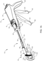
- FIG. 1A depicts an exemplary surgical stapling and severing instrument (10) that includes a handle assembly (12), a shaft assembly (14), and an end effector (16) distally projecting from shaft assembly (14).
- proximal distal
- distal distal
- end effector (16) is distal with respect to the relatively proximal handle assembly (14).
- instrument (10) may be configured and operable in accordance with at least some of the teachings of U.S. Pat. Pub. No.
- Handle assembly (12) includes several actuation mechanisms for operating end effector (16) during the surgical procedure.
- exemplary handle assembly (12) includes a saddle shaped slide (18), a closure trigger (20), and a firing trigger (22) in communication with end effector (16) via shaft assembly (14).
- slide (18) and closure trigger (20) are in open configurations, such that end effector (16) is configured to receive tissue laterally within a gap (25) between an anvil (26) and a cartridge (28) of end effector (16).
- Translating slide (18) distally toward end effector (16) slides a retaining pin (30) of end effector distally as shown in FIG. 1B for capturing the tissue between anvil (26) and cartridge (28).
- sequentially actuating closure trigger (20) and firing trigger (22) respectively compresses the tissue between anvil (26) and cartridge (28) in a closed configuration and then forms a plurality of staples (not shown) within the tissue and severs the tissue with a knife (not shown) for treatment. Additional details regarding these exemplary actuation mechanisms will be provided below in greater detail.
- handle assembly (12) has a handle housing (34), a pair of handle frame plates (35, 36) within handle housing (34) extending along shaft assembly (14), saddle shaped slide (18), closure trigger (20), and firing trigger (22) as briefly discussed above.
- Handle housing (34) defines a hand grip (38), which the operator, such as a surgeon, grasps with the palm of at least one hand.
- Handle housing (34) is formed by a right shroud handle portion (40) and a left shroud handle portion (42).
- Closure trigger (20) is proximally positioned relative to firing trigger (22) and each are pivotally mounted to frame plates (35, 36) to extend underneath a remainder of handle assembly (12) for manipulation by the fingers of the operator.
- Closure and firing triggers (20, 22) are shown in unactuated positions prior to closing end effector (16) and firing staples (not shown) and/or knife. Consequently, cartridge (28) is spaced from anvil (26) for receiving tissue within gap (25) therebetween.
- Surgical stapling instrument (10) captures tissue via a tissue retaining pin actuation mechanism (37) prior to actuation of the closure and firing triggers (20, 22).
- Retaining pin actuation mechanism (37) is mounted on an upper surface of handle housing (34) and is configured to linearly translate between proximal and distal positions.
- Slide (18) slides along slots (48) (see FIG. 1A ).
- a distal end of a push rod (50) connects to retaining pin (30) (see FIG. 1B ) such that distal movement of slide (18) causes push rod (50) to similarly slide proximally along shaft assembly (14) for moving retaining pin (30) to the closed configuration, which will be discussed below in greater detail.
- Closure mechanism (52) further includes an elongated closure member (54), with a generally U-shaped cross-section, extending distally from handle assembly (12), through shaft assembly (14), and into end effector (16) for receiving a cartridge (28) (see FIG. 2 ) at a distal end portion thereof as discussed below.
- a proximal end portion of closure member (54) is operatively connected to closure trigger (20) by a plurality of linkages configured to convert pivoting motion of closure trigger (20) into translation of closure member (54).
- closure member (54) extends through handle assembly (12) between left and right handle frame plates (35, 36).
- Closure trigger (20) descends from the slotted closure arm link (62) both toward and away from hand grip (38).
- Closure member (54) is further configured for directing movement of tissue retaining pin actuation mechanism (37) to automatically direct movement of retaining pin (30) to the closed configuration while the operator squeezes closure trigger (20).
- tissue retaining pin actuation mechanism (37) to automatically direct movement of retaining pin (30) to the closed configuration while the operator squeezes closure trigger (20).
- Such automation may be useful in the event that the operator did not manually move slide (18) to the distal position before actuating trigger (20).
- Slide (18) is thereby dragged along handle housing (34) from the proximal position to the distal position in the event that the operator did not manually manipulate slide (18) to the distal position before actuating trigger (20).
- Exemplary handle assembly (12) is configured to form the staples (not shown) and sever the tissue via a firing mechanism (80) upon operator manipulation of firing trigger (22) toward closure trigger (20) as shown in FIG. 1D .
- firing mechanism (80) which includes firing trigger (22), extends distally from handle assembly (12) and within end effector (16).
- surgical stapling instrument (10) may be further configured to releasably lock in one of a variety of configurations. The operator may then release hand grip (38) to free one or more hands for another task during the surgical procedure and, when desired, release surgical stapling instrument (10) from its locked position by release button (24).
- Surgical stapling instrument (10) of the present example includes each of handle frame plates (35, 36), push rod (50), closure member (54), and firing bar extending continuously from handle assembly (12) to end effector (16), thereby defining shaft assembly (14) extending therebetween.
- Handle frame plates (35, 36), push rod (50), closure member (54), and a firing bar of surgical stapling instrument (10) provide merely a subset of elongated components extending distally from handle assembly (12) as shaft assembly (14).
- shaft assembly (14) may include additional components, such as an articulating joint, or may include a rearrangement of various components such that shaft assembly (14) may be modular relative to handle assembly (12).
- handle assembly (12) and shaft assembly (14) may have a variety of other components, features, and operabilities, in addition to or in lieu of any of those noted above.
- Other suitable configurations for handle and shaft assemblies (12, 14) will be apparent to those of ordinary skill in the art in view of the teachings herein.
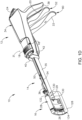
- End effector (16) includes anvil (26), replaceable cartridge (28) including a plurality of staples (not shown) and knife (not shown), and retainer pin (30). While end effector (16) of the present example is adapted for use in conjunction with replaceable cartridge (28) having various components, it will be appreciated that the concepts underlying the present invention could be applied to a variety of end effector and cartridge constructions for treating the patient.
- End effector (16) provides a surgical fastening assembly that includes cartridge (28) received within a C-shaped supporting structure (128).
- C-shaped is used throughout the specification to describe the concave nature of supporting structure (128) and cartridge (28).
- the C-shaped construction facilitates enhanced functionality and access to tissue within the patient.
- C-shaped as used herein should be construed to include a variety of concave shapes that would similarly enhance the functionality of surgical stapling and cutting instruments.
- the C-shape of supporting structure (128) may be sized to promote access to the lower colon within the pelvic bowl of a patient, such as to perform a LAR in a proctocolectomy procedure.
- Supporting structure (128) of end effector (16) is respectively attached to handle frame plates (35, 36) of shaft assembly (14) by a shoulder rivet (129) and posts (130) which extend from supporting structure (128) into receiving holes in handle frame plates (35, 36).
- the distal end of closure member (54) is disposed to receive cartridge (28) thereon for directing cartridge (28) to the closed configuration.
- Cartridge (28) includes anvil (26) coupled to a cartridge housing (132). Cartridge (28) also includes retaining pin (30) and a tissue contacting surface (34). Staples (not shown) are fired from cartridge housing (132) against a staple-forming surface of anvil (26) that faces tissue-contacting surface (134) of cartridge housing (132). Cartridge (28) may also include a removable retainer (not shown) for storage between anvil (26) and tissue contacting surface (34) prior to and/or after use in order to inhibit unintended contact with various portions of cartridge (28).
- cartridge (28) is driven toward anvil (26) via closure member (54) until reaching the closed configuration with tissue positioned between cartridge (28) and anvil (26) as discussed above with respect to handle assembly (12). While actuation of cartridge (28) includes stapling and severing tissue in this example, it will be appreciated that one or more of these steps may be omitted from treatment as desired by the operator. Moreover, it will be appreciated that surgical stapling instrument (10) may be reconfigured to perform these steps simultaneously or sequentially as desired. It should therefore be understood that the disclosure is not intended to be limited to the particular operation of surgical stapling instrument (10) or the associated treatment.
- cartridge (28) is spaced proximally from anvil (26) to receive tissue within gap (25) in the open configuration.
- the operator manually directs push rod (50) distally via slide (18).
- distally translating push rod (50) similarly translates retaining pin (30) to extend from cartridge (28) to anvil (26) and capture tissue between retaining pin (30) and guide pin (166).
- closure trigger (20) forces closure member (54) to translate distally relative to supporting structure (128) of end effector (16).
- Closure member (54) supports cartridge (28) thereon such that distal translation of closure member (54) similarly moves firing bar and cartridge (28) toward anvil (26).
- firing trigger (22) see FIG. 1D
- the operator manipulates firing trigger (22) (see FIG. 1D ) toward anvil (26) to the fired position.
- the operator may depress release button (24) and withdraw closure member (54) and firing bar proximally from the actuated, fired position to the unactuated position.
- cartridge (28) translates proximally with closure member (54), and cartridge housing (132) is held in position.
- Cartridge (28) may then be removed from supporting structure (128) of end effector (16), discarded, and replaced for further treatment if so desired.
- end effector (16) may then be removed from supporting structure (128) of end effector (16), discarded, and replaced for further treatment if so desired.
- an end effector frame (e.g. one that includes supporting structure (128)) of instrument (10) may be machined from a single solid block of material (e.g. metal).
- a single solid block of material e.g. metal
- this machining of supporting structure (128) may be time consuming and expensive, both of which are undesirable.
- Conventional machining techniques, being reductive in nature may also be considered as being inefficient since they may create waste in the material that is removed from the single solid block of material.
- supporting structure (128) may have tighter tolerances to enhance the performance of instrument (10), while other specific portions and features of supporting structure (128) may have looser tolerances where the precise dimensions are of lesser significance.
- tighter tolerances may be preferred for surfaces that aid in the coupling of staple cartridge (28) with the end effector (16) and surfaces that aid in the coupling of handle frame plates (35, 36) with the end effector frame of instrument (10).
- Various exemplary alternative frames (210, 310, 410, 510) and associated manufacturing techniques will be described in greater detail below.
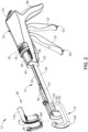
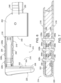
- FIGS. 3-9 show a frame (210) in accordance with the invention that may be incorporated into surgical stapling instrument (10) of FIG. 1 .
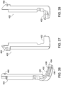
- FIG. 3 shows frame (210) as including a shaft frame (212) and an end effector frame (214) extending distally from shaft frame (212).
- Shaft frame (212) includes first and second shaft frame portions, shown as left and right handle frames (216, 218).
- End effector frame (214) includes a distal anvil support portion (220), an insert (222), and left and right support plates (224, 226) (see FIG. 5 ).
- left and right handle frames (216, 218), distal anvil support portion (220), insert (222), and left and right support plates (224, 226) are each integrally formed as a unitary piece and subsequently coupled together as discussed in greater detailed below. This prevents end effector frame (214) from being machined from a single solid block of material, which as discussed above may be time consuming and expensive.
- FIG. 4 shows an enlarged perspective view of the distal portion of frame (210) of FIG. 3 showing the coupling of shaft frame (212) and end effector frame (214) using fasteners (228a-c), as will be described in greater detail with reference to FIGS. 6-9 .
- Insert (222) includes a C-shaped track (230) disposed within an upper surface (232), with left and right flanges (234, 236) disposed laterally of upper surface (232).
- C-shaped track (230) includes an enlarged portion (238) configured to receive a distal portion of retaining pin (30) shown in FIGS. 1A-1D .
- C-shaped track (230) along with a slot of staple cartridge (28) are configured to receive a knife (not shown) therethrough to sever tissue.
- Insert (222) is configured to receive staple cartridge (28). Insert (222) may be formed for a metallic or polymeric material. More specifically, left and right flanges (234, 236) of insert (222) are configured to slidably receive corresponding portions of staple cartridge (28) as shown in FIGS. 1A-1D .
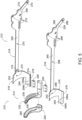
- FIG. 5 shows an exploded perspective view of frame (210) of FIG. 3 , more clearly showing left and right handle frames (216, 218) of shaft frame (212).
- left handle frame (216) includes a handle portion (239), an elongate shaft portion (240) extending distally from handle portion (239), a left curvilinear portion (242) extending distally from elongate shaft portion (240), and a connecting portion (244) extending distally from left curvilinear portion (242).
- Connecting portion (244) includes shaft alignment features (246a-b).
- right handle frame (218) includes a handle portion (248), an elongate shaft portion (250) extending distally from handle portion (248), a right curvilinear portion (252) extending distally from elongate shaft portion (250), and a connecting portion (254) extending distally from right curvilinear portion (252).
- Connecting portion (254) includes shaft alignment features (256a-b).
- Connecting portion (254) includes shaft alignment features (256a-b).
- shaft alignment features (246a-b, 256a-b) are apertures extending completely through connecting portion (244); however, other shaft alignment features (246a-b, 256a-b) are also envisioned (e.g. projections and corresponding recesses etc.).
- Left and right handle frames (216, 218) may be manufactured using a variety of methods, including one or more stamping processes, such as those discussed in greater detail with reference to FIG. 32 .
- end effector frame (214) includes distal anvil support portion (220), insert (222), and left and right support plates (224, 226).
- Distal anvil support portion (220) includes an alignment feature (258) and a curvilinear cavity (260) configured to receive insert (222).
- curvilinear cavity (260) is C-shaped. The C-shaped construction facilitates enhanced functionality and access to tissue within the patient.
- the term "C-shaped" includes a variety of concave shapes that would similarly enhance the functionality of surgical stapling and cutting instruments.
- the C-shape of supporting structure (128) may be sized to promote access to the lower colon within the pelvic bowl of a patient, such as to perform a LAR in a proctocolectomy procedure.
- insert (222) includes insert alignment features (262a-c).
- End effector frame (214) includes left and right support plates (224, 226).
- Left support plate (224) may include alignment features (264a-c)
- right support plate (226) may include alignment features (266a-c). While alignment features (262a-c, 264a-c, 266a-c) are shown as apertures extending completely through, other shaft alignment features (246a-b) are also envisioned.
- left and right handle frames (216, 218) may include a plurality of apertures (268, 270) that perform one or more functions for the operability of instrument (10).
- right handle frame (218) includes an inwardly bending portion (272) as elongate shaft portion (250) transitions to right curvilinear portion (252).
- right handle frame (218) includes a curved portion (274) having a longitudinally extending edge (276) that is configurated to mate with a longitudinally extending edge (278) of left handle frame (216).
- FIGS. 6-9 show various perspective views of the distal portion of frame (210) illustrating fasteners (228a-c).
- fasteners (228a-b) are configured to couple left and right handle frames (216, 218), left and right support plates (224, 226), and insert (222) together.
- fastener (228a) couples shaft alignment feature (246a) of left handle frame (216), alignment feature (264a) of left support plate (224), insert alignment feature (262a) of insert (222), alignment feature (266a) of right support plate (226), and shaft alignment feature (256a) of right handle frame (218).
- fastener (228b) couples shaft alignment feature (246b) of left handle frame (216), alignment feature (264a) of left support plate (224), insert alignment feature (262b) of insert (222), alignment feature (266b) of right support plate (226), and shaft alignment feature (256b) of right handle frame (218).
- Fastener (228c) is configured to couple distal anvil support portion (220), left and right support plates (224, 226), and insert (222) together.
- fastener (228c) couples alignment feature (258) of distal anvil support portion (220), alignment feature (264c) of left support plate (224), insert alignment feature (262c) of insert (222), alignment feature (266c) of right support plate (226), and alignment feature (258) of distal anvil support portion (220).
- fasteners (228a-c) are flanged welds; however, fasteners may include, for example, welds, screws, or any other suitable fastener.
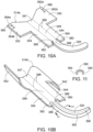
- FIG. 10A-10C show perspective views of a second exemplary frame (310) that may be incorporated into the surgical stapling instrument (10) of FIG. 1 .
- FIG. 10A-10C show end effector frame (314) at different manufacturing stages. More specifically, FIGS. 10A-10B show end effector frame (314a-b), while FIG. 10C shows an exploded perspective view of frame (310) as including a shaft frame (312) and end effector frame (314).
- Shaft frame (312) is similar in structure and function to shaft frame (412) described in greater detail below with reference to FIGS. 12-14 .
- FIG. 10A shows an end effector frame (314a), which will subsequently be formed into end effector frame (314), already being cut from a planar sheet of material, but prior to being bent into the desired shape using one or more bending processes as shown in FIGS. 10B-10C .
- end effector frame (314) includes left, central, and right curvilinear portions (342, 347, 352), left, central, and right connecting portions (344, 349, 354) extending distally from respective left, central, and right curvilinear portions (342, 347, 354), and a distal anvil support portion (320) extending distally from central connecting portion (349).
- Left and right connecting portions (344, 354) respectively include left and right alignment features, shown as left and right distally extending flanges (380, 382).
- Distal anvil support portion (320) includes left and right outwardly extending portions (384, 386) adjacent central connecting portion (349).
- At least one of left and right connecting portions (344, 354) (similar to FIG. 3 ) or left and right curvilinear portions (342, 354) (similar to FIG. 12 ) may include alignment features configured to align with alignment features (346a-c, 356a-c) of shaft frame (312).
- left curvilinear portion (342) includes alignment features (362a-b) and an aperture (388).
- Right curvilinear portion (352) includes alignment features (364a-b) and an aperture (390).
- alignment features (362a-c, 364a-c) and apertures (388, 390) may be omitted, such that shaft frame (312) may be coupled with end effector frame (314) using another method (e.g. welding).
- Central curvilinear portion (347) and central connecting portion (349) effectively form a spine for end effector frame (314a).
- end effector frame (314a) is integrally formed as a unitary piece from a single sheet of material (e.g. metal).
- FIG. 10B shows a perspective view of end effector frame (314b) after end effector frame (314a) of FIG. 10A is partially bent.
- left and right curvilinear portions (342, 352) exhibit a curvilinear shape that is further bent in FIG. 10C .
- Stamping includes a variety of forming manufacturing processes, such as punching (using a machine press or stamping press), blanking, embossing, bending, flanging, and coining.
- stamping is intended to refer to the process(es) of placing a workpiece (e.g. a metal sheet, blank) into a stamping press where a tool surface and a die surface converge to form the material into a net shape.
- end effector frame (314a) is shown as being planar after blanking, end effector frame (314a) may already be at least partially bent during the blanking process.
- Aligning features may be imparted in end effector frame (314a) prior to bending effector frame (314a). Aligning lines (388) may be applied to the surface using a marking instrument (e.g. marker, pencil, etc.) or carved into the material (e.g. laser etc.). Alternatively, aligning lines (388) may be imparted by one or more of the stamping operations.
- FIG. 11 shows a sectional view of distal anvil support portion (320) of an end effector frame (314b) of FIG. 10B taken along line 11-11 of FIG. 10B . As shown, distal anvil support portion (320) includes an upper surface (390), a left lateral surface (392), and a right lateral surface (394). As such, distal anvil support portion (320) forms an inverted U-shaped channel.
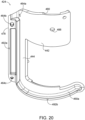
- FIG. 10C shows a perspective view of end effector frame (314) after being further bent and welded.
- FIG. 10C shows shaft frame (312) as including first and second shaft frame portions, shown as left and right handle frames (316, 318).
- left and right handle frames (316, 318) may be similar to left and right handle frames (416, 418) discussed below with reference to FIGS. 12 and 14 .
- End effector frame (214) includes distal anvil support portion (320).
- An insert, similar to insert (222) that includes C-shaped track (230), may be incorporated into distal anvil support portion (320), similar to how insert (222) was inserted into distal anvil support portion (220).
- Fastener (328) such as a shoulder rivet similar to shoulder rivet (129), is configured to couple apertures (388, 390) of left and right curvilinear portions (342, 352) with shaft alignment features (346c, 356c) of left and right handle frames (316, 318).
- Other methods of coupling shaft frame (312) with end effector frame (314) are also envisioned (e.g. welding).
- distal anvil support portion (320) is bent proximally, such that upper surface (390) of distal anvil support portion (320) extends generally perpendicular to left and right curvilinear portions (342, 352).
- Left distally extending flange (380) is welded at a distal end to left outwardly extending portion (384) and/or left lateral surface (392) using a weld (396).
- right distally extending flange (382) is welded at a distal end to right outwardly extending portion (386) and/or right lateral surface (394) using a weld (398).
- FIGS. 12-28 show a third exemplary frame that may be incorporated into surgical stapling instrument (10) of FIG. 1 .
- FIGS. 12 and 14 show frame (410) as including a shaft frame (412) and an end effector frame (414) that extends distally from shaft frame (412).
- Shaft frame (412) includes first and second shaft frame portions, shown as left and right handle frames (416, 418).
- End effector frame (414) includes an insert (422), and left and right end effector portions (424, 426).
- FIGS. 20-22 show left end effector frame portion (424), FIGS. 23-25 show right end effector frame portion (426), and
- FIGS. 26-28 show insert (422) in additional detail for greater clarity.
- left and right handle frames (416, 418), insert (422), and left and right end effector frame portions (424, 426) are each integrally formed as a unitary piece and subsequently coupled together.
- left and right handle frames (416, 418), insert (422), and left and right end effector frame portions (424, 426) may be separately formed using a variety of processes including metal injection molding.
- Metal injection molding (MIM) refers to any metalworking process where finely-powdered metal is mixed with a binder material to create a feedstock that is subsequently shaped and solidified using molding process (such as injection molding). Metal injection molding allows for high volume, complex parts to be shaped.
- left and right handle frames (416, 418), insert (422), and left and right end effector frame portions (424, 426) and each of their respective features have a molded shape. Certain features of which may be subsequently machined to a machined shape. Machining certain features may provide many benefits, including improving the dimensional tolerances of the metal injection molding process. However, it is envisioned that if desired, two or more of these components may be integrally formed together as a unitary piece.
- FIG. 13 shows an enlarged perspective view of a distal portion of frame (410) of FIG. 12 .
- insert (422) includes a C-shaped track (430) disposed within an upper surface (432) of insert (422), with left and right flanges (434, 436) separated by upper surface (432).
- C-shaped track (430) includes an enlarged portion (438) configured to receive a distal portion of retaining pin (40) shown in FIGS. 1A-1D .
- Insert (422) is configured to receive staple cartridge (28) shown in FIGS. 1A-1D .
- insert (422) is configured to slidably receive corresponding portions of staple cartridge (28). Similar to insert (222), insert (422) includes an insert alignment feature (462) configured to secure insert (222) with left and right end effector frame portions (424, 426) as discussed in greater detail with reference to FIGS. 15-17 . It is envisioned that insert (422) may be formed for a metallic or polymeric material.
- FIG. 14 shows an exploded perspective view of frame (410) of FIG. 12 , illustrating left and right handle frames (416, 418) of shaft frame (412).
- left handle frame (416) includes a handle portion (439) and an elongate shaft portion (440) extending distally from handle portion (439).
- Elongate shaft portion (440) includes shaft alignment features (446a-c), instead of connecting portion (244) including shaft alignment features (246a-b) as shown in FIG. 5 .
- right handle frame (418) includes a handle portion (448) and an elongate shaft portion (450) extending distally from handle portion (448).
- Elongate shaft portion (450) includes shaft alignment features (456a-c), instead of connecting portion (254) including shaft alignment features (256a-b) as also shown in FIG. 5 . While shaft alignment features (446a-c, 456a-c) are shown as apertures, other shaft alignment features (446a-b) are also envisioned (e.g. projections and corresponding recesses etc.).
- Left and right handle frames (416, 418) may include a plurality of apertures (468, 470) that perform one or more functions for the operability of instrument (10), similar to apertures (268, 270) shown in FIG. 5 with respect to frame (210).
- right handle frame (418) includes an inwardly bending portion (472) as elongate shaft portion (450) transitions to right curvilinear portion (452). It is envisioned that left and right handle frames (416, 418) may be manufactured using a variety of methods, including one or more stamping processes.
- FIGS. 14 and 20-22 show additional details of left end effector frame portion (424).
- Left end effector frame portion (424) includes a left curvilinear portion (442) configured to be coupled with elongate shaft portion (440), a connecting portion (444) extending distally from left curvilinear portion (442), and a left distal anvil support portion (420a) extending distally from left curvilinear portion (442).
- Left curvilinear portion (442) includes a recessed alignment portion (480) adjacent a proximal end, with alignment posts (482a-b) extending outwardly from recessed alignment portion (480). As shown in FIG.
- alignment posts (482a-b) are configured to extend through shaft alignment features (446a-b) of elongate shaft portions (440, 450).
- left distal anvil support portion (420a) includes a left curvilinear cavity portion (460a) configured to receive a portion of insert (422).
- Left end effector frame portion (424) includes a curved portion (474) having a longitudinally extending edge (478) that is configurated to mate with a longitudinally extending edge (476) of right end effector frame portion (426).
- FIGS. 14 and 23-25 show additional details of right end effector frame portion (426).
- Right end effector frame portion (426) includes a right curvilinear portion (452) configured to be coupled with elongate shaft portion (450), a connecting portion (454) extending distally from right curvilinear portion (452), and a right distal anvil support portion (420b) extending distally from right curvilinear portion (452).
- Right curvilinear portion (452) includes a recessed alignment portion (484) with alignment posts (486a-b) extending outwardly from recessed alignment portion (480). Alignment posts (486a-b) are configured to extend through shaft alignment features (456a-b). As shown in FIG.
- right distal anvil support portion (420b) includes a right curvilinear cavity portion (460b) configured to receive another portion of insert (422). As such, left and right curvilinear cavity portions (460a-b) collectively receive a bottom surface of insert (222).
- FIGS. 13 and 14 show the coupling of shaft frame (412) with end effector frame (414) in greater detail.
- shaft frame (412) and end effector frame (414) are coupled together using a fastener (428), shown as a shoulder rivet similar to rivet (129) in FIGS. 1A-1D .
- Left and right curvilinear portions (442, 452) include respective apertures (488, 490).
- Fastener (428) is configured to couple apertures (488, 490) of left and right curvilinear portions (442, 452) with shaft alignment features (446c, 456c) of left and right handle frames (416, 418).
- FIGS. 15-17 show the coupling of left and right end effector frame portion (424, 426) and insert (422).
- left end effector frame portion (424) includes alignment features (464a-c) and contacting surfaces (492a-b) configured to contact right end effector frame portion (426) .
- right end effector frame portion (426) includes alignment features (466a-c) and contacting surfaces (494a-b) configured to contact left end effector frame portion (424).
- a fastener shown as a spring pin (458), is configured to couple insert (422), and left and right end effector frame portions (424, 426) together.
- spring pin (458) extends completely through alignment features (462, 464a, 466a). While alignment features (462, 464a, 466a) are shown as apertures extending completely through the respective insert (222), left end effector frame portion (424), and right end effector frame portion (426), other alignment features are also envisioned.
- alignment features (462b-c, 464b-c) of left and right end effector frame portions (424, 426) are located between left and right end effector frame portion (424, 426) and not visible along an outer surface of end effector frame (414) once left and right end effector frame portions (424, 426) are coupled together. While alignment features (464b-c) are shown as recesses and alignment features (466b-c) are shown as projections, a variety of other alignment features having various shapes are also envisioned. It is also envisioned that alignment features (464b-c) may be projections and alignment features (466b-c) may be projections. It is also envisioned that alignment features (464b-c) include at least one projection and at least one recess, such that alignment features (466b-c) include at least one corresponding recess and at least one projection.
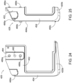
- FIGS. 29-31 show a fourth exemplary frame (510) that may be incorporated into the surgical stapling instrument of FIG. 1 .
- FIG. 29 shows frame (510) as including a shaft frame (512) and an end effector frame (514) that extends distally from shaft frame (512) and is coupled with shaft frame (512) using one or more fasteners (528).
- Shaft frame (512) includes first and second shaft frame portions, shown as left and right handle frames (516, 518).
- Left handle frame (516) includes handle portion (539), an elongate shaft portion (540), shaft alignment features (546a-b), and apertures (568).
- right handle frame (518) includes a handle portion (548), an elongate shaft portion (550), shaft alignment features (556a-b), and apertures (568).
- End effector frame (514) includes a distal anvil support portion (520), a left end effector frame portion (524), right end effector frame portion (526), C-shaped track (530), upper surface (532), left flange (534), right flange (536), enlarged portion (538), left and right curvilinear portions (542, 552), connecting portions (544, 554), recessed portions (580, 584), alignment posts (582a-b, 586a-b), apertures (588, 590).
- End effector frame (514) may be formed using additive manufacturing, such that end effector frame (514) may be integrally formed together as a unitary piece. Additive manufacturing includes material extrusion, directed energy deposition, material jetting (e.g.
- Powder bed fusion includes direct metal laser sintering (DMI,S), selective laser sintering (SLS), selective heat sintering (SHS), electron beam melting (EBM) and direct metal laser melting (DMLM).
- DMI,S direct metal laser sintering
- SLS selective laser sintering
- SHS selective heat sintering
- EBM electron beam melting
- DMLM direct metal laser melting
- end effector frame (514) is formed using 3-D printing.
- Machining specific features may allow for initial molded geometries having better mold flow characteristics for the metal injection molding process. These features may include for example left and right flanges (534, 536), recessed portions (580, 584), alignment posts (582, 586) which are shaded (using hatching) in FIGS. 30-31 . As shown, left flange includes leading portion (534a), adjacent a left lateral surface (534b), an arcuate recessed portion (534c), and a lower surface (534d). Similarly, right flange (536) includes leading surface (536a), adjacent a right lateral surface (536b), an arcuate recessed surface (536c), and a lower surface (536d).
- each surface (334a-d, 536a-d) is shown as being machined; one or more surfaces (334a-d, 536a-d) may be machined. These machining operations may leave indication marks on the connected side walls that show where machining was used, and the amount of material removed.
- using a metal injection molding process and subsequent machining provides frame (210, 310, 410, 510) with higher performance machined features on the same distal component. Additionally, method (510) provides a superior surface finish than metal injection molding is capable of alone.
- FIG. 32 shows a first exemplary method (610) of manufacturing frame (210, 310, 410, 510) of surgical instrument (10) that includes steps (612, 614, 616, 618, 620).
- method (610) includes manufacturing a first portion of frame (210, 310, 410, 510) of surgical instrument (10) using a stamping or additive manufacturing machine (622).
- First portion includes a first curvilinear portion ((e.g. curvilinear portions (242, 252, 242, 352, 442, 452, 542, 552)) of an end effector frame (214, 314, 414, 514) and a first alignment feature.
- manufacturing the first portion may include stamping or using additive manufacturing (e.g. metal injection molding, 3-D printing) of the first portion.
- method (610) includes manufacturing a second portion of frame (210, 310, 410, 510) of surgical instrument (10) using a stamping or additive manufacturing machine (624).
- Second portion includes a second alignment feature.
- manufacturing the second portion may include stamping, metal injection molding, or 3-D printing the second portion.
- method (610) includes manufacturing a third portion of frame (210, 310, 410, 510) of surgical instrument (10) separate from either of the first or second portions.
- the third portion includes a C-shaped track (230, 430, 530).
- Third portion may be manufactured, for example, from metal using metal injection molding or from a polymeric material using an injection molding machine (626).
- method (610) includes aligning the first portion with the second portion by aligning first and second alignment features of first and second portions of instrument (10) together.
- method (610) includes coupling first and second portions of frame (210, 310, 410, 510) of instrument (10) together.
- FIG. 33 shows a second exemplary method (710) of manufacturing frame (410, 510) of surgical instrument (10) that includes steps (712, 714, 716).
- method (710) includes forming end effector frame (414, 514) of frame (410, 510) using additive manufacturing.
- an additive manufacturing machine (718) e.g. a metal injection molding machine or 3-D printer
- End effector frame (414, 514) has at least one feature having an initial shape.
- additive manufacturing includes material extrusion, directed energy deposition, material jetting (e.g. 3-D printing), binder jetting, sheet lamination, vat polymerization, and powder bed fusion.
- Powder bed fusion includes direct metal laser sintering (DMLS), selective laser sintering (SLS), selective heat sintering (SHS), electron beam melting (EBM) and direct metal laser melting (DMLM).
- DMLS direct metal laser sintering
- SLS selective laser sintering
- SHS selective heat sintering
- EBM electron beam melting
- DMLM direct metal laser melting
- end effector frame (514) is formed using 3-D printing.
- method (710) includes machining at least one feature of end effector frame (414, 514) to have a machined shape without machining entire end effector frame (414, 514) using a lathe (720). Machining removes material from at least one feature (e.g. left and right flanges (434, 436, 534, 536), recessed portion (480, 484, 580, 584), alignment posts (482, 486, 582, 586)), such that the dimensions of the initial shape are greater than the dimensions of the machined shape of the at least one feature. Other features may also be machined where enhanced properties are desired. As shown, at step (714), method (710) includes coupling end effector frame (414, 514) into surgical instrument (10).
- an end effector in accordance with various embodiments can comprise electrodes configured to heat and seal the tissue.
- an end effector in accordance with certain embodiments can apply vibrational energy to seal the tissue.
- Versions of the devices described above may be designed to be disposed of after a single use, or they can be designed to be used multiple times. Versions may, in either or both cases, be reconditioned for reuse after at least one use. Reconditioning may include any combination of the steps of disassembly of the device, followed by cleaning or replacement of particular pieces, and subsequent reassembly. In particular, some versions of the device may be disassembled, and any number of the particular pieces or parts of the device may be selectively replaced or removed in any combination. Upon cleaning and/or replacement of particular parts, some versions of the device may be reassembled for subsequent use either at a reconditioning facility, or by an operator immediately prior to a procedure.
- reconditioning of a device may utilize a variety of techniques for disassembly, cleaning/replacement, and reassembly. Use of such techniques, and the resulting reconditioned device, are all within the scope of the present application.
- versions described herein may be sterilized before and/or after a procedure.
- the device is placed in a closed and sealed container, such as a plastic or TYVEK bag.
- the container and device may then be placed in a field of radiation that can penetrate the container, such as gamma radiation, x-rays, or high-energy electrons.
- the radiation may kill bacteria on the device and in the container.
- the sterilized device may then be stored in the sterile container for later use.
- a device may also be sterilized using any other technique known in the art, including but not limited to beta or gamma radiation, ethylene oxide, or steam.
Description
- Some surgical staplers are operable to clamp down on one or more layers of patient tissue, form staples through the layers of tissue to substantially seal the layers of tissue together near the formed staples, and cut through the layers of tissue for forming severed ends of operatively sealed tissue. An exemplary stapling instrument may include a pair of cooperating elongate jaw members, where each jaw member may be adapted to be inserted into a patient and positioned relative to tissue that is to be stapled and/or incised. One of the jaw members may support a staple cartridge with at least two laterally spaced rows of staples contained therein, and the other jaw member may support an anvil with staple-forming pockets aligned with the rows of staples in the staple cartridge. Generally, the stapling instrument may further include a pusher bar and a knife blade that are slidable relative to the jaw members to sequentially or simultaneously eject the staples from the staple cartridge via camming surfaces on the pusher bar and/or camming surfaces on a wedge sled that is pushed by the pusher bar. The camming surfaces may be configured to activate one or more staple drivers carried by the cartridge and associated with the staples in order to push the staples against the anvil and form laterally spaced rows of deformed staples in the tissue gripped between the jaw members. Such rows may be arranged as linear rows and/or arcuate rows for sequentially or simultaneously stapling and cutting the tissue of the patient in the form of a predetermined pattern. The knife blade may trail the camming surfaces and cut the tissue along a linear or arcuate line between the rows of staples formed in the tissue.
- Merely exemplary surgical staplers are disclosed in
U.S. Pat. No. 6,988,650, entitled "Retaining Pin Lever Advancement Mechanism for a Curved Cutter Stapler," issued January 24, 2006 ;U.S. Pat. No. 7,134,587, entitled "Knife Retraction Arm for a Curved Cutter Stapler," issued November 14, 2006 ;U.S. Pat. No. 7,147,139, entitled "Closure Plate Lockout for a Curved Cutter Stapler," issued December 12, 2006 ,U.S. Pat. No. 7,147,140, entitled "Cartridge Retainer for a Curved Cutter Stapler," issued December 12, 2006 ;U.S. Pat. No. 7,204,404, entitled "Slotted Pins Guiding Knife in a Curved Cutter Stapler," issued April 17, 2007 ; andU.S. Pat. No. 7,207,472, entitled "Cartridge with Locking Knife for a Curved Cutter Stapler," issued April 24, 2007 . Additional merely exemplary surgical staplers are disclosed inU.S. Pat. Pub. No. 2005/0139636, entitled "Replaceable Cartridge Module for a Surgical Stapling and Cutting Instrument," published on June 30, 2005 , now abandoned;U.S. Pat. Pub. No. 2005/0143759, entitled "Curved Cutter Stapler Shaped for Male Pelvis," published on June 30, 2005 , now abandoned; andU.S. Pat. Pub. No. 2005/0145672, entitled "Curved Cutter Stapler with Aligned Tissue Retention Feature," published on July 7, 2005 , now abandoned. -
EP3329862 A2 discloses a surgical stapling instrument comprising a handle assembly, an elongated body portion extending from the handle assembly, and an end effector supported on a distal portion of the elongated body portion. The end effector includes a curved housing having a base portion and a jaw portion, a curved anvil assembly supported on the jaw portion, and a curved cartridge assembly supported on the base portion. The cartridge assembly defining first and second arrays of staples receiving slots, the first array of staple receiving slots includes three rows of staples and the second array of staple receiving slots includes two rows of staples. A height of the staples in each of the rows of three rows of staples of the first array of staple receiving slots is different. -
WO2014/04397 A1 - A surgical stapler may be inserted into a patient to perform colorectal surgery. Such procedures may include the use of the stapler to operatively seal, sever, and remove the colon of the patient, in whole or in part. For instance, a proctocolectomy may be performed during a lower anterior resection ("LAR") for treating and inhibiting the spread of colorectal cancer cells. Of course, surgical staplers may be used in various other settings and procedures.
- While various kinds of surgical stapling instruments and associated components have been made and used, it is believed that no one prior to the inventor(s) has made or used the invention described in the appended claim.
- The accompanying drawings, which are incorporated in and constitute a part of this specification, illustrate embodiments of the disclosure, and, together with the general description of the invention given above, and the detailed description of the embodiments given below, serve to explain the principles of the present invention. The invention is shown in
figures 3-9 . The other embodiments are included for illustrative purposes only. -
FIG. 1A depicts a right front perspective view of an exemplary surgical stapling instrument with a pin actuation mechanism in an open position and a staple cartridge in open position; -
FIG. 1B depicts a right front perspective view of the surgical stapling instrument ofFIG. 1A with the pin actuation mechanism in a closed position and the staple cartridge in the open position; -
FIG. 1C depicts a right front perspective view of the surgical stapling instrument ofFIG. 1A with the pin actuation mechanism in the closed position and the staple cartridge in a closed position via actuation of a closure mechanism; -
FIG. 1D depicts a right front perspective view of the surgical stapling instrument ofFIG. 1A with the pin actuation mechanism and the staple cartridge in the closed positions and a firing trigger in a fired position for stapling and cutting tissue of a patient; -
FIG. 2 depicts a partially exploded right front perspective view of the surgical stapling instrument ofFIG. 1A showing the staple cartridge removed from a remainder of an end effector; -
FIG. 3 depicts a right rear perspective view of a frame in accordance with the invention that may be incorporated into the surgical stapling instrument ofFIG. 1 ; -
FIG. 4 depicts an enlarged right rear perspective view of a distal portion of the frame ofFIG. 3 ; -
FIG. 5 depicts an exploded right rear perspective view of the frame ofFIG. 3 , with the frame including left and right handle frames, left and right support plates, a distal anvil support portion, and an insert coupled together with fasteners; -
FIG. 6 depicts a left top perspective view of the distal portion ofFIG. 4 ; -
FIG. 7 depicts a left top sectional view of the distal portion ofFIG. 6 with fasteners coupling the frame together; -
FIG. 8 depicts a right bottom perspective view of the distal portion ofFIG. 4 ; -
FIG. 9 depicts a left rear perspective view of the distal portion ofFIG. 4 ; -
FIG. 10A depicts a perspective view of a distal portion of a second exemplary frame that may be incorporated into the surgical stapling instrument ofFIG. 1 prior to being bent; -
FIG. 10B depicts a perspective view of the distal portion of the frame ofFIG. 10A after being bent; -
FIG. 10C depicts a perspective view of the distal portion of the frame ofFIG. 10B after being bent and welded and coupled with a shaft frame; -
FIG. 11 depicts a sectional view of a distal anvil support portion of the distal portion of the frame ofFIG. 10B taken along line 11-11 ofFIG. 10B ; -
FIG. 12 depicts right rear perspective view of a third exemplary frame that may be incorporated into the surgical stapling instrument ofFIG. 1 ; -
FIG. 13 depicts an enlarged right rear perspective view of a distal portion of the frame ofFIG. 12 ; -
FIG. 14 depicts an exploded right rear perspective view of the frame ofFIG. 12 , where the frame includes left and right handle frames, left and right end effector frame portions, and an insert; -
FIG. 15 depicts a top right perspective view of an end effector frame that includes the left and right distal end effector portions and the insert ofFIG. 13 ; -
FIG. 16 depicts a top right sectional view of the end effector portion ofFIG. 15 including interior alignment features and a fastener; -
FIG. 17 depicts an enlarged top right sectional view of the end effector frame ofFIG. 15 , with the fastener extending through the end effector frame; -
FIG. 18 depicts a right plan view of the end effector frame ofFIG. 12 ; -
FIG. 19 depicts a left plan view of the end effector frame ofFIG. 12 ; -
FIG. 20 depicts left perspective view of a left end effector frame portion ofFIG. 14 ; -
FIG. 21 depicts a right plan view of the left end effector frame portion ofFIG. 20 ; -
FIG. 22 depicts a left plan view of the left end effector frame portion ofFIG. 20 ; -
FIG. 23 depicts right perspective view of the right effector frame portion ofFIG. 14 ; -
FIG. 24 depicts a left plan view of the right effector frame portion ofFIG. 23 ; -
FIG. 25 depicts a rear plan view of the right effector frame portion ofFIG. 23 ; -
FIG. 26 depicts a left front perspective view of the insert ofFIG. 14 ; -
FIG. 27 depicts a rear plan view of the insert ofFIG. 26 ; -
FIG. 28 depicts a right plan view of the insert ofFIG. 26 ; -
FIG. 29 depicts a right rear perspective view of a fourth exemplary frame that may be incorporated into the surgical stapling instrument ofFIG. 1 ; -
FIG. 30 depicts a right rear perspective view of an end effector frame of the frame ofFIG. 29 ; -
FIG. 31 depicts left rear perspective view of the end effector frame ofFIG. 30 ; -
FIG. 32 depicts an exemplary method of manufacturing the frame ofFIG. 3 that may be incorporated into the surgical stapling instrument ofFIG. 1 ; and -
FIG. 33 depicts an exemplary method of manufacturing the frame ofFIG. 14 that may be incorporated into the surgical stapling instrument ofFIG. 1 . - The drawings are not intended to be limiting in any way, and it is contemplated that various embodiments of the invention may be carried out in a variety of other ways, including those not necessarily depicted in the drawings. The accompanying drawings incorporated in and forming a part of the specification illustrate several aspects of the present disclosure, and together with the description serve to explain the principles of the invention; it being understood, however, that this invention is not limited to the precise arrangements shown.
- The invention is defined in claim 1. For clarity of disclosure, the terms "proximal" and "distal" are defined herein relative to a human or robotic operator of the surgical instrument. The term "proximal" refers the position of an element closer to the human or robotic operator of the surgical instrument and further away from the surgical end effector of the surgical instrument. The term "distal" refers to the position of an element closer to the surgical end effector of the surgical instrument and further away from the human or robotic operator of the surgical instrument. It will be further appreciated that for convenience and clarity, spatial terms such as "vertical," "horizontal," "lower," "upper," "front," and "rear" are used herein with respect to the drawings. However, surgical instruments are used in many orientations and positions, and these terms are not intended to be limiting and/or absolute.
-
FIG. 1A depicts an exemplary surgical stapling and severing instrument (10) that includes a handle assembly (12), a shaft assembly (14), and an end effector (16) distally projecting from shaft assembly (14). It should be understood that terms such as "proximal," "distal," "right," and "left" are used herein with reference to a clinician gripping handle assembly (12) of surgical stapling instrument (10). Thus, end effector (16) is distal with respect to the relatively proximal handle assembly (14). Except as otherwise described herein, instrument (10) may be configured and operable in accordance with at least some of the teachings ofU.S. Pat. Pub. No. 2005/0143759, entitled "Curved Cutter Stapler Shaped for Male Pelvis," published on June 30, 2005 , now abandoned; and/orU.S. Pat. Pub. No. 2017/0027571, entitled "Surgical Instrument Comprising Systems for Assuring the Proper Sequential Operation of the Surgical Instrument," published on February 2, 2017 . - Handle assembly (12) includes several actuation mechanisms for operating end effector (16) during the surgical procedure. To this end, exemplary handle assembly (12) includes a saddle shaped slide (18), a closure trigger (20), and a firing trigger (22) in communication with end effector (16) via shaft assembly (14). As shown in
FIG. 1A , slide (18) and closure trigger (20) are in open configurations, such that end effector (16) is configured to receive tissue laterally within a gap (25) between an anvil (26) and a cartridge (28) of end effector (16). Translating slide (18) distally toward end effector (16) slides a retaining pin (30) of end effector distally as shown inFIG. 1B for capturing the tissue between anvil (26) and cartridge (28). With respect toFIGS. 1C and1D , sequentially actuating closure trigger (20) and firing trigger (22) respectively compresses the tissue between anvil (26) and cartridge (28) in a closed configuration and then forms a plurality of staples (not shown) within the tissue and severs the tissue with a knife (not shown) for treatment. Additional details regarding these exemplary actuation mechanisms will be provided below in greater detail. - As shown in
FIGS. 1A , handle assembly (12) has a handle housing (34), a pair of handle frame plates (35, 36) within handle housing (34) extending along shaft assembly (14), saddle shaped slide (18), closure trigger (20), and firing trigger (22) as briefly discussed above. Handle housing (34) defines a hand grip (38), which the operator, such as a surgeon, grasps with the palm of at least one hand. Handle housing (34) is formed by a right shroud handle portion (40) and a left shroud handle portion (42). Closure trigger (20) is proximally positioned relative to firing trigger (22) and each are pivotally mounted to frame plates (35, 36) to extend underneath a remainder of handle assembly (12) for manipulation by the fingers of the operator. Closure and firing triggers (20, 22) are shown in unactuated positions prior to closing end effector (16) and firing staples (not shown) and/or knife. Consequently, cartridge (28) is spaced from anvil (26) for receiving tissue within gap (25) therebetween. - Surgical stapling instrument (10) captures tissue via a tissue retaining pin actuation mechanism (37) prior to actuation of the closure and firing triggers (20, 22). Retaining pin actuation mechanism (37) is mounted on an upper surface of handle housing (34) and is configured to linearly translate between proximal and distal positions. Slide (18) slides along slots (48) (see
FIG. 1A ). A distal end of a push rod (50) connects to retaining pin (30) (seeFIG. 1B ) such that distal movement of slide (18) causes push rod (50) to similarly slide proximally along shaft assembly (14) for moving retaining pin (30) to the closed configuration, which will be discussed below in greater detail. - A closure mechanism (52), which includes closure trigger (20), is configured to selectively move cartridge (28) toward the tissue positioned between anvil (26) and cartridge (28) in the closed configuration in anticipation of stapling and/or cutting the tissue. Closure mechanism (52) further includes an elongated closure member (54), with a generally U-shaped cross-section, extending distally from handle assembly (12), through shaft assembly (14), and into end effector (16) for receiving a cartridge (28) (see
FIG. 2 ) at a distal end portion thereof as discussed below. A proximal end portion of closure member (54) is operatively connected to closure trigger (20) by a plurality of linkages configured to convert pivoting motion of closure trigger (20) into translation of closure member (54). More particularly, the intermediate and proximal end portions of closure member (54) extend through handle assembly (12) between left and right handle frame plates (35, 36). Closure trigger (20) descends from the slotted closure arm link (62) both toward and away from hand grip (38). Closure member (54) is further configured for directing movement of tissue retaining pin actuation mechanism (37) to automatically direct movement of retaining pin (30) to the closed configuration while the operator squeezes closure trigger (20). Such automation may be useful in the event that the operator did not manually move slide (18) to the distal position before actuating trigger (20). Slide (18) is thereby dragged along handle housing (34) from the proximal position to the distal position in the event that the operator did not manually manipulate slide (18) to the distal position before actuating trigger (20). - The operator further squeezes the closure trigger (20) to hand grip (38) as shown in
FIG. 1C to effectively set surgical stapling instrument (10) in the closed configuration prior to forming the staples (not shown) and severing the tissue as discussed briefly above. Exemplary handle assembly (12) is configured to form the staples (not shown) and sever the tissue via a firing mechanism (80) upon operator manipulation of firing trigger (22) toward closure trigger (20) as shown inFIG. 1D . With respect toFIGS. 1C-1D , firing mechanism (80), which includes firing trigger (22), extends distally from handle assembly (12) and within end effector (16). - Upon operator release of one or both of closure and firing triggers (20, 22) while one or both of triggers (20, 22) is/are in a fired position, or in an intermediate position between the unactuated and fired positions, surgical stapling instrument (10) may be further configured to releasably lock in one of a variety of configurations. The operator may then release hand grip (38) to free one or more hands for another task during the surgical procedure and, when desired, release surgical stapling instrument (10) from its locked position by release button (24).
- Surgical stapling instrument (10) of the present example includes each of handle frame plates (35, 36), push rod (50), closure member (54), and firing bar extending continuously from handle assembly (12) to end effector (16), thereby defining shaft assembly (14) extending therebetween. Handle frame plates (35, 36), push rod (50), closure member (54), and a firing bar of surgical stapling instrument (10) provide merely a subset of elongated components extending distally from handle assembly (12) as shaft assembly (14). Alternatively, shaft assembly (14) may include additional components, such as an articulating joint, or may include a rearrangement of various components such that shaft assembly (14) may be modular relative to handle assembly (12). In any case, it will be appreciated that the disclosure is not intended to be limited to shaft assembly (14) described herein, and may include various alternative arrangements for operatively connecting end effector (16) to handle assembly (12). Of course, handle assembly (12) and shaft assembly (14) may have a variety of other components, features, and operabilities, in addition to or in lieu of any of those noted above. Other suitable configurations for handle and shaft assemblies (12, 14) will be apparent to those of ordinary skill in the art in view of the teachings herein.
- End effector (16) includes anvil (26), replaceable cartridge (28) including a plurality of staples (not shown) and knife (not shown), and retainer pin (30). While end effector (16) of the present example is adapted for use in conjunction with replaceable cartridge (28) having various components, it will be appreciated that the concepts underlying the present invention could be applied to a variety of end effector and cartridge constructions for treating the patient.
- End effector (16) provides a surgical fastening assembly that includes cartridge (28) received within a C-shaped supporting structure (128). The term C-shaped is used throughout the specification to describe the concave nature of supporting structure (128) and cartridge (28). The C-shaped construction facilitates enhanced functionality and access to tissue within the patient. The term "C-shaped" as used herein should be construed to include a variety of concave shapes that would similarly enhance the functionality of surgical stapling and cutting instruments. By way of example only, the C-shape of supporting structure (128) may be sized to promote access to the lower colon within the pelvic bowl of a patient, such as to perform a LAR in a proctocolectomy procedure. Supporting structure (128) of end effector (16) is respectively attached to handle frame plates (35, 36) of shaft assembly (14) by a shoulder rivet (129) and posts (130) which extend from supporting structure (128) into receiving holes in handle frame plates (35, 36). The distal end of closure member (54) is disposed to receive cartridge (28) thereon for directing cartridge (28) to the closed configuration.
- Cartridge (28) includes anvil (26) coupled to a cartridge housing (132). Cartridge (28) also includes retaining pin (30) and a tissue contacting surface (34). Staples (not shown) are fired from cartridge housing (132) against a staple-forming surface of anvil (26) that faces tissue-contacting surface (134) of cartridge housing (132). Cartridge (28) may also include a removable retainer (not shown) for storage between anvil (26) and tissue contacting surface (34) prior to and/or after use in order to inhibit unintended contact with various portions of cartridge (28).
- In the present example, cartridge (28) is driven toward anvil (26) via closure member (54) until reaching the closed configuration with tissue positioned between cartridge (28) and anvil (26) as discussed above with respect to handle assembly (12). While actuation of cartridge (28) includes stapling and severing tissue in this example, it will be appreciated that one or more of these steps may be omitted from treatment as desired by the operator. Moreover, it will be appreciated that surgical stapling instrument (10) may be reconfigured to perform these steps simultaneously or sequentially as desired. It should therefore be understood that the disclosure is not intended to be limited to the particular operation of surgical stapling instrument (10) or the associated treatment.
- As shown in
FIG. 1A , cartridge (28) is spaced proximally from anvil (26) to receive tissue within gap (25) in the open configuration. With tissue received between cartridge (28) and anvil (26), the operator manually directs push rod (50) distally via slide (18). Thus, distally translating push rod (50) similarly translates retaining pin (30) to extend from cartridge (28) to anvil (26) and capture tissue between retaining pin (30) and guide pin (166). - As shown in
FIG. 1C , manipulation of closure trigger (20) forces closure member (54) to translate distally relative to supporting structure (128) of end effector (16). Closure member (54) supports cartridge (28) thereon such that distal translation of closure member (54) similarly moves firing bar and cartridge (28) toward anvil (26). With cartridge (28) in the closed configuration and the tissue effectively captured in the end effector (16), the operator manipulates firing trigger (22) (seeFIG. 1D ) toward anvil (26) to the fired position. Once fired, the operator may depress release button (24) and withdraw closure member (54) and firing bar proximally from the actuated, fired position to the unactuated position. At approximately the same time, as cartridge (28) translates proximally with closure member (54), and cartridge housing (132) is held in position. Cartridge (28) may then be removed from supporting structure (128) of end effector (16), discarded, and replaced for further treatment if so desired. Of course, various suitable settings and procedures in which surgical stapling instrument (10) may be used will be apparent to those of ordinary skill in the art in view of the teachings herein. - In some conventional manufacturing processes, an end effector frame (e.g. one that includes supporting structure (128)) of instrument (10) may be machined from a single solid block of material (e.g. metal). As a result, this machining of supporting structure (128) may be time consuming and expensive, both of which are undesirable. As a result, it is desirable to manufacture the frame using a faster, more efficient, and more cost-effective process or system of processes. Conventional machining techniques, being reductive in nature, may also be considered as being inefficient since they may create waste in the material that is removed from the single solid block of material. Additionally, it may be desirable that specific portions and features of supporting structure (128) have tighter tolerances to enhance the performance of instrument (10), while other specific portions and features of supporting structure (128) may have looser tolerances where the precise dimensions are of lesser significance. For example, tighter tolerances may be preferred for surfaces that aid in the coupling of staple cartridge (28) with the end effector (16) and surfaces that aid in the coupling of handle frame plates (35, 36) with the end effector frame of instrument (10). As such, it is desirable to manufacture a frame (210, 310, 410, 510) efficiently, cost effectively, and robustly. Various exemplary alternative frames (210, 310, 410, 510) and associated manufacturing techniques will be described in greater detail below.
-
FIGS. 3-9 show a frame (210) in accordance with the invention that may be incorporated into surgical stapling instrument (10) ofFIG. 1 .FIG. 3 shows frame (210) as including a shaft frame (212) and an end effector frame (214) extending distally from shaft frame (212). Shaft frame (212) includes first and second shaft frame portions, shown as left and right handle frames (216, 218). End effector frame (214) includes a distal anvil support portion (220), an insert (222), and left and right support plates (224, 226) (seeFIG. 5 ). As shown, left and right handle frames (216, 218), distal anvil support portion (220), insert (222), and left and right support plates (224, 226) are each integrally formed as a unitary piece and subsequently coupled together as discussed in greater detailed below. This prevents end effector frame (214) from being machined from a single solid block of material, which as discussed above may be time consuming and expensive. -
FIG. 4 shows an enlarged perspective view of the distal portion of frame (210) ofFIG. 3 showing the coupling of shaft frame (212) and end effector frame (214) using fasteners (228a-c), as will be described in greater detail with reference toFIGS. 6-9 . Insert (222) includes a C-shaped track (230) disposed within an upper surface (232), with left and right flanges (234, 236) disposed laterally of upper surface (232). C-shaped track (230) includes an enlarged portion (238) configured to receive a distal portion of retaining pin (30) shown inFIGS. 1A-1D . C-shaped track (230) along with a slot of staple cartridge (28) are configured to receive a knife (not shown) therethrough to sever tissue. Insert (222) is configured to receive staple cartridge (28). Insert (222) may be formed for a metallic or polymeric material. More specifically, left and right flanges (234, 236) of insert (222) are configured to slidably receive corresponding portions of staple cartridge (28) as shown inFIGS. 1A-1D . -
FIG. 5 shows an exploded perspective view of frame (210) ofFIG. 3 , more clearly showing left and right handle frames (216, 218) of shaft frame (212). As shown, left handle frame (216) includes a handle portion (239), an elongate shaft portion (240) extending distally from handle portion (239), a left curvilinear portion (242) extending distally from elongate shaft portion (240), and a connecting portion (244) extending distally from left curvilinear portion (242). Connecting portion (244) includes shaft alignment features (246a-b). Similarly, right handle frame (218) includes a handle portion (248), an elongate shaft portion (250) extending distally from handle portion (248), a right curvilinear portion (252) extending distally from elongate shaft portion (250), and a connecting portion (254) extending distally from right curvilinear portion (252). Connecting portion (254) includes shaft alignment features (256a-b). Connecting portion (254) includes shaft alignment features (256a-b). As shown, shaft alignment features (246a-b, 256a-b) are apertures extending completely through connecting portion (244); however, other shaft alignment features (246a-b, 256a-b) are also envisioned (e.g. projections and corresponding recesses etc.). Left and right handle frames (216, 218) may be manufactured using a variety of methods, including one or more stamping processes, such as those discussed in greater detail with reference toFIG. 32 . - As shown in
FIG. 5 , end effector frame (214) includes distal anvil support portion (220), insert (222), and left and right support plates (224, 226). Distal anvil support portion (220) includes an alignment feature (258) and a curvilinear cavity (260) configured to receive insert (222). As previously described with respect to supporting structure (128), curvilinear cavity (260) is C-shaped. The C-shaped construction facilitates enhanced functionality and access to tissue within the patient. The term "C-shaped" includes a variety of concave shapes that would similarly enhance the functionality of surgical stapling and cutting instruments. By way of example only, the C-shape of supporting structure (128) may be sized to promote access to the lower colon within the pelvic bowl of a patient, such as to perform a LAR in a proctocolectomy procedure. Similarly, insert (222) includes insert alignment features (262a-c). End effector frame (214) includes left and right support plates (224, 226). Left support plate (224) may include alignment features (264a-c), and right support plate (226) may include alignment features (266a-c). While alignment features (262a-c, 264a-c, 266a-c) are shown as apertures extending completely through, other shaft alignment features (246a-b) are also envisioned. - As shown in
FIG. 5 , left and right handle frames (216, 218) may include a plurality of apertures (268, 270) that perform one or more functions for the operability of instrument (10). Additionally, right handle frame (218) includes an inwardly bending portion (272) as elongate shaft portion (250) transitions to right curvilinear portion (252). As shown inFIGS. 5 and8 , right handle frame (218) includes a curved portion (274) having a longitudinally extending edge (276) that is configurated to mate with a longitudinally extending edge (278) of left handle frame (216). -
FIGS. 6-9 show various perspective views of the distal portion of frame (210) illustrating fasteners (228a-c). As shown, fasteners (228a-b) are configured to couple left and right handle frames (216, 218), left and right support plates (224, 226), and insert (222) together. As shown inFIG. 7 , fastener (228a) couples shaft alignment feature (246a) of left handle frame (216), alignment feature (264a) of left support plate (224), insert alignment feature (262a) of insert (222), alignment feature (266a) of right support plate (226), and shaft alignment feature (256a) of right handle frame (218). Similarly, fastener (228b) couples shaft alignment feature (246b) of left handle frame (216), alignment feature (264a) of left support plate (224), insert alignment feature (262b) of insert (222), alignment feature (266b) of right support plate (226), and shaft alignment feature (256b) of right handle frame (218). Fastener (228c) is configured to couple distal anvil support portion (220), left and right support plates (224, 226), and insert (222) together. More specifically, fastener (228c) couples alignment feature (258) of distal anvil support portion (220), alignment feature (264c) of left support plate (224), insert alignment feature (262c) of insert (222), alignment feature (266c) of right support plate (226), and alignment feature (258) of distal anvil support portion (220). As shown, fasteners (228a-c) are flanged welds; however, fasteners may include, for example, welds, screws, or any other suitable fastener. -
FIG. 10A-10C show perspective views of a second exemplary frame (310) that may be incorporated into the surgical stapling instrument (10) ofFIG. 1 .FIG. 10A-10C show end effector frame (314) at different manufacturing stages. More specifically,FIGS. 10A-10B show end effector frame (314a-b), whileFIG. 10C shows an exploded perspective view of frame (310) as including a shaft frame (312) and end effector frame (314). Shaft frame (312) is similar in structure and function to shaft frame (412) described in greater detail below with reference toFIGS. 12-14 . -
FIG. 10A shows an end effector frame (314a), which will subsequently be formed into end effector frame (314), already being cut from a planar sheet of material, but prior to being bent into the desired shape using one or more bending processes as shown inFIGS. 10B-10C . As shown inFIG. 10A , end effector frame (314) includes left, central, and right curvilinear portions (342, 347, 352), left, central, and right connecting portions (344, 349, 354) extending distally from respective left, central, and right curvilinear portions (342, 347, 354), and a distal anvil support portion (320) extending distally from central connecting portion (349). Left and right connecting portions (344, 354) respectively include left and right alignment features, shown as left and right distally extending flanges (380, 382). Distal anvil support portion (320) includes left and right outwardly extending portions (384, 386) adjacent central connecting portion (349). - At least one of left and right connecting portions (344, 354) (similar to
FIG. 3 ) or left and right curvilinear portions (342, 354) (similar toFIG. 12 ) may include alignment features configured to align with alignment features (346a-c, 356a-c) of shaft frame (312). As shown inFIG. 10A , left curvilinear portion (342) includes alignment features (362a-b) and an aperture (388). Right curvilinear portion (352) includes alignment features (364a-b) and an aperture (390). However, alignment features (362a-c, 364a-c) and apertures (388, 390) may be omitted, such that shaft frame (312) may be coupled with end effector frame (314) using another method (e.g. welding). Central curvilinear portion (347) and central connecting portion (349) effectively form a spine for end effector frame (314a). As shown, end effector frame (314a) is integrally formed as a unitary piece from a single sheet of material (e.g. metal). -
FIG. 10B shows a perspective view of end effector frame (314b) after end effector frame (314a) ofFIG. 10A is partially bent. As shown, left and right curvilinear portions (342, 352) exhibit a curvilinear shape that is further bent inFIG. 10C . Stamping includes a variety of forming manufacturing processes, such as punching (using a machine press or stamping press), blanking, embossing, bending, flanging, and coining. As used herein, stamping is intended to refer to the process(es) of placing a workpiece (e.g. a metal sheet, blank) into a stamping press where a tool surface and a die surface converge to form the material into a net shape. While end effector frame (314a) is shown as being planar after blanking, end effector frame (314a) may already be at least partially bent during the blanking process. - Aligning features, shown as aligning lines (388) in
FIGS. 10A-10B , may be imparted in end effector frame (314a) prior to bending effector frame (314a). Aligning lines (388) may be applied to the surface using a marking instrument (e.g. marker, pencil, etc.) or carved into the material (e.g. laser etc.). Alternatively, aligning lines (388) may be imparted by one or more of the stamping operations.FIG. 11 shows a sectional view of distal anvil support portion (320) of an end effector frame (314b) ofFIG. 10B taken along line 11-11 ofFIG. 10B . As shown, distal anvil support portion (320) includes an upper surface (390), a left lateral surface (392), and a right lateral surface (394). As such, distal anvil support portion (320) forms an inverted U-shaped channel. -
FIG. 10C shows a perspective view of end effector frame (314) after being further bent and welded.FIG. 10C shows shaft frame (312) as including first and second shaft frame portions, shown as left and right handle frames (316, 318). As previously discussed, left and right handle frames (316, 318) may be similar to left and right handle frames (416, 418) discussed below with reference toFIGS. 12 and14 . End effector frame (214) includes distal anvil support portion (320). An insert, similar to insert (222) that includes C-shaped track (230), may be incorporated into distal anvil support portion (320), similar to how insert (222) was inserted into distal anvil support portion (220). Fastener (328), such as a shoulder rivet similar to shoulder rivet (129), is configured to couple apertures (388, 390) of left and right curvilinear portions (342, 352) with shaft alignment features (346c, 356c) of left and right handle frames (316, 318). Other methods of coupling shaft frame (312) with end effector frame (314) are also envisioned (e.g. welding). - As shown in
FIG. 10C , distal anvil support portion (320) is bent proximally, such that upper surface (390) of distal anvil support portion (320) extends generally perpendicular to left and right curvilinear portions (342, 352). Left distally extending flange (380) is welded at a distal end to left outwardly extending portion (384) and/or left lateral surface (392) using a weld (396). Similarly, right distally extending flange (382) is welded at a distal end to right outwardly extending portion (386) and/or right lateral surface (394) using a weld (398). Welds (396, 398) longitudinally and rotatably secure distal anvil support portion (320) with left, central, and right connecting portions (344, 349, 354). Moreover, welding left and right distally extending flanges (380, 382) and/or left and right lateral surfaces (392, 394) to distal anvil support portion (320) improves the mating of these distal features and tightens the tolerance of the radius of curvature of distal anvil support portion (320). -
FIGS. 12-28 show a third exemplary frame that may be incorporated into surgical stapling instrument (10) ofFIG. 1 .FIGS. 12 and14 show frame (410) as including a shaft frame (412) and an end effector frame (414) that extends distally from shaft frame (412). Shaft frame (412) includes first and second shaft frame portions, shown as left and right handle frames (416, 418). End effector frame (414) includes an insert (422), and left and right end effector portions (424, 426).FIGS. 20-22 show left end effector frame portion (424),FIGS. 23-25 show right end effector frame portion (426), andFIGS. 26-28 show insert (422) in additional detail for greater clarity. - As shown, left and right handle frames (416, 418), insert (422), and left and right end effector frame portions (424, 426) are each integrally formed as a unitary piece and subsequently coupled together. For example, left and right handle frames (416, 418), insert (422), and left and right end effector frame portions (424, 426) may be separately formed using a variety of processes including metal injection molding. Metal injection molding (MIM) refers to any metalworking process where finely-powdered metal is mixed with a binder material to create a feedstock that is subsequently shaped and solidified using molding process (such as injection molding). Metal injection molding allows for high volume, complex parts to be shaped. As will be described in greater detail below, left and right handle frames (416, 418), insert (422), and left and right end effector frame portions (424, 426) and each of their respective features have a molded shape. Certain features of which may be subsequently machined to a machined shape. Machining certain features may provide many benefits, including improving the dimensional tolerances of the metal injection molding process. However, it is envisioned that if desired, two or more of these components may be integrally formed together as a unitary piece.
-
FIG. 13 shows an enlarged perspective view of a distal portion of frame (410) ofFIG. 12 . As shown inFIG. 13 and in greater detail with reference toFIGS. 26-28 , insert (422) includes a C-shaped track (430) disposed within an upper surface (432) of insert (422), with left and right flanges (434, 436) separated by upper surface (432). C-shaped track (430) includes an enlarged portion (438) configured to receive a distal portion of retaining pin (40) shown inFIGS. 1A-1D . Insert (422) is configured to receive staple cartridge (28) shown inFIGS. 1A-1D . More specifically, left and right flanges (434, 436) of insert (422) are configured to slidably receive corresponding portions of staple cartridge (28). Similar to insert (222), insert (422) includes an insert alignment feature (462) configured to secure insert (222) with left and right end effector frame portions (424, 426) as discussed in greater detail with reference toFIGS. 15-17 . It is envisioned that insert (422) may be formed for a metallic or polymeric material. -
FIG. 14 shows an exploded perspective view of frame (410) ofFIG. 12 , illustrating left and right handle frames (416, 418) of shaft frame (412). As shown, left handle frame (416) includes a handle portion (439) and an elongate shaft portion (440) extending distally from handle portion (439). Elongate shaft portion (440) includes shaft alignment features (446a-c), instead of connecting portion (244) including shaft alignment features (246a-b) as shown inFIG. 5 . Similarly, right handle frame (418) includes a handle portion (448) and an elongate shaft portion (450) extending distally from handle portion (448). Elongate shaft portion (450) includes shaft alignment features (456a-c), instead of connecting portion (254) including shaft alignment features (256a-b) as also shown inFIG. 5 . While shaft alignment features (446a-c, 456a-c) are shown as apertures, other shaft alignment features (446a-b) are also envisioned (e.g. projections and corresponding recesses etc.). Left and right handle frames (416, 418) may include a plurality of apertures (468, 470) that perform one or more functions for the operability of instrument (10), similar to apertures (268, 270) shown inFIG. 5 with respect to frame (210). Additionally, right handle frame (418) includes an inwardly bending portion (472) as elongate shaft portion (450) transitions to right curvilinear portion (452). It is envisioned that left and right handle frames (416, 418) may be manufactured using a variety of methods, including one or more stamping processes. -
FIGS. 14 and20-22 show additional details of left end effector frame portion (424). Left end effector frame portion (424) includes a left curvilinear portion (442) configured to be coupled with elongate shaft portion (440), a connecting portion (444) extending distally from left curvilinear portion (442), and a left distal anvil support portion (420a) extending distally from left curvilinear portion (442). Left curvilinear portion (442) includes a recessed alignment portion (480) adjacent a proximal end, with alignment posts (482a-b) extending outwardly from recessed alignment portion (480). As shown inFIG. 13 , alignment posts (482a-b) are configured to extend through shaft alignment features (446a-b) of elongate shaft portions (440, 450). As shown inFIGS. 20 and22 , left distal anvil support portion (420a) includes a left curvilinear cavity portion (460a) configured to receive a portion of insert (422). Left end effector frame portion (424) includes a curved portion (474) having a longitudinally extending edge (478) that is configurated to mate with a longitudinally extending edge (476) of right end effector frame portion (426). -
FIGS. 14 and23-25 show additional details of right end effector frame portion (426). Right end effector frame portion (426) includes a right curvilinear portion (452) configured to be coupled with elongate shaft portion (450), a connecting portion (454) extending distally from right curvilinear portion (452), and a right distal anvil support portion (420b) extending distally from right curvilinear portion (452). Right curvilinear portion (452) includes a recessed alignment portion (484) with alignment posts (486a-b) extending outwardly from recessed alignment portion (480). Alignment posts (486a-b) are configured to extend through shaft alignment features (456a-b). As shown inFIG. 23 , right distal anvil support portion (420b) includes a right curvilinear cavity portion (460b) configured to receive another portion of insert (422). As such, left and right curvilinear cavity portions (460a-b) collectively receive a bottom surface of insert (222). -
FIGS. 13 and14 show the coupling of shaft frame (412) with end effector frame (414) in greater detail. As shown, shaft frame (412) and end effector frame (414) are coupled together using a fastener (428), shown as a shoulder rivet similar to rivet (129) inFIGS. 1A-1D . Left and right curvilinear portions (442, 452) include respective apertures (488, 490). Fastener (428) is configured to couple apertures (488, 490) of left and right curvilinear portions (442, 452) with shaft alignment features (446c, 456c) of left and right handle frames (416, 418). -
FIGS. 15-17 show the coupling of left and right end effector frame portion (424, 426) and insert (422). As shown, left end effector frame portion (424) includes alignment features (464a-c) and contacting surfaces (492a-b) configured to contact right end effector frame portion (426) . Similarly, right end effector frame portion (426) includes alignment features (466a-c) and contacting surfaces (494a-b) configured to contact left end effector frame portion (424). A fastener, shown as a spring pin (458), is configured to couple insert (422), and left and right end effector frame portions (424, 426) together. As shown inFIG. 16 , spring pin (458) extends completely through alignment features (462, 464a, 466a). While alignment features (462, 464a, 466a) are shown as apertures extending completely through the respective insert (222), left end effector frame portion (424), and right end effector frame portion (426), other alignment features are also envisioned. - As shown in
FIG. 16 alignment features (462b-c, 464b-c) of left and right end effector frame portions (424, 426) are located between left and right end effector frame portion (424, 426) and not visible along an outer surface of end effector frame (414) once left and right end effector frame portions (424, 426) are coupled together. While alignment features (464b-c) are shown as recesses and alignment features (466b-c) are shown as projections, a variety of other alignment features having various shapes are also envisioned. It is also envisioned that alignment features (464b-c) may be projections and alignment features (466b-c) may be projections. It is also envisioned that alignment features (464b-c) include at least one projection and at least one recess, such that alignment features (466b-c) include at least one corresponding recess and at least one projection. -
FIGS. 29-31 show a fourth exemplary frame (510) that may be incorporated into the surgical stapling instrument ofFIG. 1 .FIG. 29 shows frame (510) as including a shaft frame (512) and an end effector frame (514) that extends distally from shaft frame (512) and is coupled with shaft frame (512) using one or more fasteners (528). Shaft frame (512) includes first and second shaft frame portions, shown as left and right handle frames (516, 518). Left handle frame (516) includes handle portion (539), an elongate shaft portion (540), shaft alignment features (546a-b), and apertures (568). Similarly, right handle frame (518) includes a handle portion (548), an elongate shaft portion (550), shaft alignment features (556a-b), and apertures (568). - End effector frame (514) includes a distal anvil support portion (520), a left end effector frame portion (524), right end effector frame portion (526), C-shaped track (530), upper surface (532), left flange (534), right flange (536), enlarged portion (538), left and right curvilinear portions (542, 552), connecting portions (544, 554), recessed portions (580, 584), alignment posts (582a-b, 586a-b), apertures (588, 590). End effector frame (514) may be formed using additive manufacturing, such that end effector frame (514) may be integrally formed together as a unitary piece. Additive manufacturing includes material extrusion, directed energy deposition, material jetting (e.g. 3-D printing), binder jetting, sheet lamination, vat polymerization, and powder bed fusion. Powder bed fusion includes direct metal laser sintering (DMI,S), selective laser sintering (SLS), selective heat sintering (SHS), electron beam melting (EBM) and direct metal laser melting (DMLM). As shown, end effector frame (514) is formed using 3-D printing.
- Machining specific features may allow for initial molded geometries having better mold flow characteristics for the metal injection molding process. These features may include for example left and right flanges (534, 536), recessed portions (580, 584), alignment posts (582, 586) which are shaded (using hatching) in
FIGS. 30-31 . As shown, left flange includes leading portion (534a), adjacent a left lateral surface (534b), an arcuate recessed portion (534c), and a lower surface (534d). Similarly, right flange (536) includes leading surface (536a), adjacent a right lateral surface (536b), an arcuate recessed surface (536c), and a lower surface (536d). While each surface (334a-d, 536a-d) is shown as being machined; one or more surfaces (334a-d, 536a-d) may be machined. These machining operations may leave indication marks on the connected side walls that show where machining was used, and the amount of material removed. As such, using a metal injection molding process and subsequent machining provides frame (210, 310, 410, 510) with higher performance machined features on the same distal component. Additionally, method (510) provides a superior surface finish than metal injection molding is capable of alone. -
FIG. 32 shows a first exemplary method (610) of manufacturing frame (210, 310, 410, 510) of surgical instrument (10) that includes steps (612, 614, 616, 618, 620). As shown, at step (612), method (610) includes manufacturing a first portion of frame (210, 310, 410, 510) of surgical instrument (10) using a stamping or additive manufacturing machine (622). First portion includes a first curvilinear portion ((e.g. curvilinear portions (242, 252, 242, 352, 442, 452, 542, 552)) of an end effector frame (214, 314, 414, 514) and a first alignment feature. For example, manufacturing the first portion may include stamping or using additive manufacturing (e.g. metal injection molding, 3-D printing) of the first portion. - As shown, at step (614), method (610) includes manufacturing a second portion of frame (210, 310, 410, 510) of surgical instrument (10) using a stamping or additive manufacturing machine (624). Second portion includes a second alignment feature. For example, manufacturing the second portion may include stamping, metal injection molding, or 3-D printing the second portion. As shown, at step (616), method (610) includes manufacturing a third portion of frame (210, 310, 410, 510) of surgical instrument (10) separate from either of the first or second portions. The third portion includes a C-shaped track (230, 430, 530). Third portion may be manufactured, for example, from metal using metal injection molding or from a polymeric material using an injection molding machine (626). As shown, at step (618), method (610) includes aligning the first portion with the second portion by aligning first and second alignment features of first and second portions of instrument (10) together. As shown, at step (620), method (610) includes coupling first and second portions of frame (210, 310, 410, 510) of instrument (10) together.
-
FIG. 33 shows a second exemplary method (710) of manufacturing frame (410, 510) of surgical instrument (10) that includes steps (712, 714, 716). As shown, at step (712), method (710) includes forming end effector frame (414, 514) of frame (410, 510) using additive manufacturing. As shown, an additive manufacturing machine (718) (e.g. a metal injection molding machine or 3-D printer) may be used. End effector frame (414, 514) has at least one feature having an initial shape. As previously indicated, additive manufacturing includes material extrusion, directed energy deposition, material jetting (e.g. 3-D printing), binder jetting, sheet lamination, vat polymerization, and powder bed fusion. Powder bed fusion includes direct metal laser sintering (DMLS), selective laser sintering (SLS), selective heat sintering (SHS), electron beam melting (EBM) and direct metal laser melting (DMLM). As shown, end effector frame (514) is formed using 3-D printing. - As shown, at step (712), method (710) includes machining at least one feature of end effector frame (414, 514) to have a machined shape without machining entire end effector frame (414, 514) using a lathe (720). Machining removes material from at least one feature (e.g. left and right flanges (434, 436, 534, 536), recessed portion (480, 484, 580, 584), alignment posts (482, 486, 582, 586)), such that the dimensions of the initial shape are greater than the dimensions of the machined shape of the at least one feature. Other features may also be machined where enhanced properties are desired. As shown, at step (714), method (710) includes coupling end effector frame (414, 514) into surgical instrument (10).
- The surgical instrument systems described herein have been described in connection with the deployment and deformation of staples; however, the embodiments described herein are not so limited. Various embodiments are envisioned which deploy fasteners other than staples, such as clamps or tacks, for example. Moreover, various embodiments are envisioned which utilize any suitable means for sealing tissue. For instance, an end effector in accordance with various embodiments can comprise electrodes configured to heat and seal the tissue. Also, for instance, an end effector in accordance with certain embodiments can apply vibrational energy to seal the tissue.
- Versions of the devices described above may be designed to be disposed of after a single use, or they can be designed to be used multiple times. Versions may, in either or both cases, be reconditioned for reuse after at least one use. Reconditioning may include any combination of the steps of disassembly of the device, followed by cleaning or replacement of particular pieces, and subsequent reassembly. In particular, some versions of the device may be disassembled, and any number of the particular pieces or parts of the device may be selectively replaced or removed in any combination. Upon cleaning and/or replacement of particular parts, some versions of the device may be reassembled for subsequent use either at a reconditioning facility, or by an operator immediately prior to a procedure. Those skilled in the art will appreciate that reconditioning of a device may utilize a variety of techniques for disassembly, cleaning/replacement, and reassembly. Use of such techniques, and the resulting reconditioned device, are all within the scope of the present application.
- By way of example only, versions described herein may be sterilized before and/or after a procedure. In one sterilization technique, the device is placed in a closed and sealed container, such as a plastic or TYVEK bag. The container and device may then be placed in a field of radiation that can penetrate the container, such as gamma radiation, x-rays, or high-energy electrons. The radiation may kill bacteria on the device and in the container. The sterilized device may then be stored in the sterile container for later use. A device may also be sterilized using any other technique known in the art, including but not limited to beta or gamma radiation, ethylene oxide, or steam.
- The entire disclosures of:
U.S. Patent No. 5,403,312, entitled "Electrosurgical Hemostatic Device," which issued on April 4, 1995 ;U.S. Patent No. 7,000,818, entitled "Surgical Stapling Instrument having Separate Distinct Closing and Firing Systems," which issued on February 21, 2006 ;U.S. Patent No. 7,422,139, entitled "Motor-Driven Surgical Cutting and Fastening Instrument with Tactile Position Feedback," which issued on September 9, 2008 ;U.S. Patent No. 7,464,849, entitled "Electro-Mechanical Surgical Instrument with Closure System and Anvil Alignment Components," which issued on December 16, 2008 ;U.S. Patent No. 7,670,334, entitled "Surgical Instrument Having An Articulating End Effector," which issued on March 2, 2010 ;U.S. Patent No. 7,753,245, entitled "Surgical Stapling Instruments," which issued on July 13, 2010 ;U.S. Patent No. 8,393,514, entitled "Selectively Orientable Implantable Fastener Cartridge," which issued on March 12, 2013 ;U.S. Patent No. 7,845,537, entitled "Surgical Instrument Having Recording Capabilities," which issued on December 7, 2010 ;U.S. Patent Application Serial No. 12/031,573, entitled "Surgical Cutting And Fastening Instrument Having RF Electrodes," filed February 14, 2008 ;U.S. Patent No. 7,980,443, entitled "End Effectors For A Surgical Cutting And Stapling Instrument," which issued on July 19, 2011 ;U.S. Patent No. 8,210,411 entitled "Motor-Driven Surgical Cutting Instrument," which issued on July 3, 2012 ;U.S. Patent No. 8,608,045, entitled "Powered Surgical Cutting And Stapling Apparatus With Manually Retractable Firing System," which issued on December 17, 2013 ;U.S. Patent No. 8,220,688, entitled "Motor-Driven Surgical Cutting Instrument with Electric Actuator Directional Control Assembly," which issued on July 17, 2012 ;U.S. Patent No. 8,733,613, entitled "Staple Cartridge," which issued on May 27, 2014 ;U.S. Patent No. 8,561,870, entitled "Surgical Stapling Instrument," which issued on October 22, 2013 ;U.S. Patent No. 9,072,535, entitled "Surgical Stapling Instruments With Rotatable Staple Deployment Arrangements," which issued on July 7, 2015 U.S. Patent No. 9,101,358, entitled "Articulatable Surgical Instrument Comprising A Firing Drive," which issued on August 11, 2015 U.S. Patent No. 9,345,481, entitled "Staple Cartridge Tissue Thickness Sensor System," which issued on May 24, 2016 U.S. Patent Application Publication No. 2014/0263552, entitled "Staple Cartridge Tissue Thickness Sensor System," published on September 18, 2014 , now abandoned;U.S. Patent Application Publication No. 2007/0175955, entitled "Surgical Cutting And Fastening Instrument With Closure Trigger Locking Mechanism," published on January 31, 2006 , now abandoned; andU.S. Patent No. 8,308,040, entitled "Surgical Stapling Instrument With An Articulatable End Effector," issued on November 12, 2012 , are hereby referenced.
Claims (1)
- A frame (210) of a curved surgical stapler (10) comprising:(a) an end effector frame (214);(b) a shaft frame (212) extending proximally from the end effector frame, wherein the shaft frame includes:(i) a first portion (216) that includes a first curvilinear portion (242) and a first alignment feature (246a-b);(ii) a second portion (218) that includes a second curvilinear portion (252) and a second alignment feature (256a-b); and(c) a fastener (228a-b) configured to couple the first and second alignment features of the first and second portions together, characterized in thatthe end effector frame includes a distal anvil support portion (220) and an insert (222) configured to receive a staple cartridge, wherein the distal anvil support portion includes a third alignment feature (258), wherein the insert includes first and second insert alignment features (262a-c), wherein the fastener is configured to couple first and second alignment features of first and second portions with the first insert alignment feature (262a-b) of the insert, the frame further comprising a second fastener (228c) configured to couple the third alignment feature of distal anvil support portion with the 2. second insert alignment feature (262c) of the insert.
Applications Claiming Priority (1)
| Application Number | Priority Date | Filing Date | Title |
|---|---|---|---|
| US16/236,703 US11259804B2 (en) | 2018-12-31 | 2018-12-31 | Frame for surgical stapler and associated method of manufacture with stamping |
Publications (4)
| Publication Number | Publication Date |
|---|---|
| EP3673833A2 EP3673833A2 (en) | 2020-07-01 |
| EP3673833A3 EP3673833A3 (en) | 2020-09-02 |
| EP3673833C0 EP3673833C0 (en) | 2023-11-22 |
| EP3673833B1 true EP3673833B1 (en) | 2023-11-22 |
Family
ID=69055882
Family Applications (1)
| Application Number | Title | Priority Date | Filing Date |
|---|---|---|---|
| EP19220103.6A Active EP3673833B1 (en) | 2018-12-31 | 2019-12-30 | Frame for surgical stapler and associated method of manufacture with stamping |
Country Status (6)
| Country | Link |
|---|---|
| US (2) | US11259804B2 (en) |
| EP (1) | EP3673833B1 (en) |
| JP (1) | JP2022515657A (en) |
| CN (1) | CN113226197A (en) |
| BR (1) | BR112021012700A2 (en) |
| WO (1) | WO2020141401A1 (en) |
Families Citing this family (2)
| Publication number | Priority date | Publication date | Assignee | Title |
|---|---|---|---|---|
| US11291450B2 (en) * | 2018-12-31 | 2022-04-05 | Cilag Gmbh International | Anvil for circular surgical stapler and associated method of manufacture with MIM |
| US11103245B2 (en) * | 2018-12-31 | 2021-08-31 | Cilag Gmbh International | Knife for surgical stapler and associated method of manufacture with MIM and hip |
Family Cites Families (81)
| Publication number | Priority date | Publication date | Assignee | Title |
|---|---|---|---|---|
| US3157308A (en) | 1961-09-05 | 1964-11-17 | Clark Mfg Co J L | Canister type container and method of making the same |
| US5366459A (en) | 1987-05-14 | 1994-11-22 | Inbae Yoon | Surgical clip and clip application procedures |
| GR920100358A (en) | 1991-08-23 | 1993-06-07 | Ethicon Inc | Surgical anastomosis stapling instrument. |
| US5350104A (en) | 1991-08-23 | 1994-09-27 | Ethicon, Inc. | Sealing means for endoscopic surgical anastomosis stapling instrument |
| US5333773A (en) | 1991-08-23 | 1994-08-02 | Ethicon, Inc. | Sealing means for endoscopic surgical anastomosis stapling instrument |
| US5163945A (en) | 1991-10-18 | 1992-11-17 | Ethicon, Inc. | Surgical clip applier |
| US5342373A (en) | 1992-09-14 | 1994-08-30 | Ethicon, Inc. | Sterile clips and instrument for their placement |
| US5403312A (en) | 1993-07-22 | 1995-04-04 | Ethicon, Inc. | Electrosurgical hemostatic device |
| US5431668A (en) | 1993-04-29 | 1995-07-11 | Ethicon, Inc. | Ligating clip applier |
| CA2143560C (en) | 1994-03-02 | 2007-01-16 | Mark Fogelberg | Sterile occlusion fasteners and instrument and method for their placement |
| US5810240A (en) * | 1996-03-15 | 1998-09-22 | United States Surgical Corporation | Surgical fastener applying device |
| US5951574A (en) | 1998-10-23 | 1999-09-14 | Ethicon Endo-Surgery, Inc. | Multiple clip applier having a split feeding mechanism |
| US6805273B2 (en) * | 2002-11-04 | 2004-10-19 | Federico Bilotti | Surgical stapling instrument |
| DE10026683C2 (en) | 2000-05-30 | 2003-07-10 | Ethicon Endo Surgery Europe | Surgical stapling device |
| US6817508B1 (en) * | 2000-10-13 | 2004-11-16 | Tyco Healthcare Group, Lp | Surgical stapling device |
| US7407076B2 (en) * | 2000-10-13 | 2008-08-05 | Tyco Healthcare Group Lp | Surgical stapling device |
| US6978921B2 (en) | 2003-05-20 | 2005-12-27 | Ethicon Endo-Surgery, Inc. | Surgical stapling instrument incorporating an E-beam firing mechanism |
| US7380696B2 (en) | 2003-05-20 | 2008-06-03 | Ethicon Endo-Surgery, Inc. | Articulating surgical stapling instrument incorporating a two-piece E-beam firing mechanism |
| US20050143759A1 (en) | 2003-12-30 | 2005-06-30 | Kelly William D. | Curved cutter stapler shaped for male pelvis |
| US7207472B2 (en) | 2003-12-30 | 2007-04-24 | Ethicon Endo-Surgery, Inc. | Cartridge with locking knife for a curved cutter stapler |
| US7147139B2 (en) | 2003-12-30 | 2006-12-12 | Ethicon Endo-Surgery, Inc | Closure plate lockout for a curved cutter stapler |
| US7147140B2 (en) | 2003-12-30 | 2006-12-12 | Ethicon Endo - Surgery, Inc. | Cartridge retainer for a curved cutter stapler |
| US7204404B2 (en) * | 2003-12-30 | 2007-04-17 | Ethicon Endo-Surgery, Inc. | Slotted pins guiding knife in a curved cutter stapler |
| US7134587B2 (en) | 2003-12-30 | 2006-11-14 | Ethicon Endo-Surgery, Inc. | Knife retraction arm for a curved cutter stapler |
| US20050139636A1 (en) | 2003-12-30 | 2005-06-30 | Schwemberger Richard F. | Replaceable cartridge module for a surgical stapling and cutting instrument |
| US20050145672A1 (en) | 2003-12-30 | 2005-07-07 | Schwemberger Richard F. | Curved cutter stapler with aligned tissue retention feature |
| US6988650B2 (en) | 2003-12-30 | 2006-01-24 | Ethicon Endo-Surgery, Inc. | Retaining pin lever advancement mechanism for a curved cutter stapler |
| US7731724B2 (en) | 2005-04-14 | 2010-06-08 | Ethicon Endo-Surgery, Inc. | Surgical clip advancement and alignment mechanism |
| US7261724B2 (en) | 2005-04-14 | 2007-08-28 | Ethicon Endo-Surgery, Inc. | Surgical clip advancement mechanism |
| US7686820B2 (en) | 2005-04-14 | 2010-03-30 | Ethicon Endo-Surgery, Inc. | Surgical clip applier ratchet mechanism |
| US8038686B2 (en) | 2005-04-14 | 2011-10-18 | Ethicon Endo-Surgery, Inc. | Clip applier configured to prevent clip fallout |
| US7699860B2 (en) | 2005-04-14 | 2010-04-20 | Ethicon Endo-Surgery, Inc. | Surgical clip |
| US7670334B2 (en) | 2006-01-10 | 2010-03-02 | Ethicon Endo-Surgery, Inc. | Surgical instrument having an articulating end effector |
| US20070175955A1 (en) | 2006-01-31 | 2007-08-02 | Shelton Frederick E Iv | Surgical cutting and fastening instrument with closure trigger locking mechanism |
| US7422139B2 (en) | 2006-01-31 | 2008-09-09 | Ethicon Endo-Surgery, Inc. | Motor-driven surgical cutting fastening instrument with tactile position feedback |
| US7845537B2 (en) | 2006-01-31 | 2010-12-07 | Ethicon Endo-Surgery, Inc. | Surgical instrument having recording capabilities |
| US7464849B2 (en) | 2006-01-31 | 2008-12-16 | Ethicon Endo-Surgery, Inc. | Electro-mechanical surgical instrument with closure system and anvil alignment components |
| US20070181631A1 (en) * | 2006-02-07 | 2007-08-09 | Ethicon Endo-Surgery, Inc. | Apparatus for performing trans-anal resection |
| US8308040B2 (en) | 2007-06-22 | 2012-11-13 | Ethicon Endo-Surgery, Inc. | Surgical stapling instrument with an articulatable end effector |
| US7753245B2 (en) | 2007-06-22 | 2010-07-13 | Ethicon Endo-Surgery, Inc. | Surgical stapling instruments |
| US8561870B2 (en) | 2008-02-13 | 2013-10-22 | Ethicon Endo-Surgery, Inc. | Surgical stapling instrument |
| US7980443B2 (en) | 2008-02-15 | 2011-07-19 | Ethicon Endo-Surgery, Inc. | End effectors for a surgical cutting and stapling instrument |
| US8210411B2 (en) | 2008-09-23 | 2012-07-03 | Ethicon Endo-Surgery, Inc. | Motor-driven surgical cutting instrument |
| US8608045B2 (en) | 2008-10-10 | 2013-12-17 | Ethicon Endo-Sugery, Inc. | Powered surgical cutting and stapling apparatus with manually retractable firing system |
| US8262679B2 (en) | 2009-10-09 | 2012-09-11 | Ethicon Endo-Surgery, Inc. | Clip advancer |
| US8220688B2 (en) | 2009-12-24 | 2012-07-17 | Ethicon Endo-Surgery, Inc. | Motor-driven surgical cutting instrument with electric actuator directional control assembly |
| US8733613B2 (en) | 2010-09-29 | 2014-05-27 | Ethicon Endo-Surgery, Inc. | Staple cartridge |
| US8840003B2 (en) | 2010-09-30 | 2014-09-23 | Ethicon Endo-Surgery, Inc. | Surgical stapling instrument with compact articulation control arrangement |
| US8746532B2 (en) | 2011-05-19 | 2014-06-10 | Ethicon Endo-Surgery, Inc. | Anvil and cartridge alignment configuration for a circular stapler |
| US9072535B2 (en) | 2011-05-27 | 2015-07-07 | Ethicon Endo-Surgery, Inc. | Surgical stapling instruments with rotatable staple deployment arrangements |
| CN102835983B (en) * | 2011-06-21 | 2016-08-17 | 伊西康内外科公司 | Linear staplers |
| US9125651B2 (en) * | 2011-12-07 | 2015-09-08 | Ethicon Endo-Surgery, Inc. | Reusable linear stapler cartridge device for tissue thickness measurement |
| US9101358B2 (en) | 2012-06-15 | 2015-08-11 | Ethicon Endo-Surgery, Inc. | Articulatable surgical instrument comprising a firing drive |
| CN102835984B (en) * | 2012-09-18 | 2014-07-02 | 常州市康迪医用吻合器有限公司 | Cutting anastomat for surgical operation |
| CN102895010B (en) | 2012-11-02 | 2014-12-24 | 北京中法派尔特医疗设备有限公司 | Arc-shaped cutting stitching instrument |
| US9717497B2 (en) | 2013-02-28 | 2017-08-01 | Ethicon Llc | Lockout feature for movable cutting member of surgical instrument |
| US9867615B2 (en) | 2013-02-28 | 2018-01-16 | Ethicon Llc | Surgical instrument with articulation lock having a detenting binary spring |
| US9808248B2 (en) | 2013-02-28 | 2017-11-07 | Ethicon Llc | Installation features for surgical instrument end effector cartridge |
| US9186142B2 (en) | 2013-02-28 | 2015-11-17 | Ethicon Endo-Surgery, Inc. | Surgical instrument end effector articulation drive with pinion and opposing racks |
| US10092292B2 (en) | 2013-02-28 | 2018-10-09 | Ethicon Llc | Staple forming features for surgical stapling instrument |
| US9839421B2 (en) | 2013-02-28 | 2017-12-12 | Ethicon Llc | Jaw closure feature for end effector of surgical instrument |
| US9517065B2 (en) | 2013-02-28 | 2016-12-13 | Ethicon Endo-Surgery, Llc | Integrated tissue positioning and jaw alignment features for surgical stapler |
| US9795379B2 (en) | 2013-02-28 | 2017-10-24 | Ethicon Llc | Surgical instrument with multi-diameter shaft |
| US9345481B2 (en) | 2013-03-13 | 2016-05-24 | Ethicon Endo-Surgery, Llc | Staple cartridge tissue thickness sensor system |
| US10729444B2 (en) | 2017-04-28 | 2020-08-04 | Ethicon Llc | Liquid-immune trigger circuit for surgical instrument |
| US9713469B2 (en) | 2013-09-23 | 2017-07-25 | Ethicon Llc | Surgical stapler with rotary cam drive |
| US9936949B2 (en) | 2013-09-23 | 2018-04-10 | Ethicon Llc | Surgical stapling instrument with drive assembly having toggle features |
| US10478189B2 (en) | 2015-06-26 | 2019-11-19 | Ethicon Llc | Method of applying an annular array of staples to tissue |
| US9907552B2 (en) | 2013-09-23 | 2018-03-06 | Ethicon Llc | Control features for motorized surgical stapling instrument |
| US10709452B2 (en) | 2013-09-23 | 2020-07-14 | Ethicon Llc | Methods and systems for performing circular stapling |
| US10695068B2 (en) | 2017-04-28 | 2020-06-30 | Ethicon Llc | Hysteresis removal feature in surgical stapling instrument |
| US10980542B2 (en) | 2016-11-14 | 2021-04-20 | Ethicon Llc | Circular surgical stapler with recessed deck |
| US20180132849A1 (en) | 2016-11-14 | 2018-05-17 | Ethicon Endo-Surgery, Llc | Staple forming pocket configurations for circular surgical stapler anvil |
| US20150083772A1 (en) | 2013-09-23 | 2015-03-26 | Ethicon Endo-Surgery, Inc. | Surgical stapler with rotary cam drive and return |
| RU2657204C2 (en) * | 2014-04-04 | 2018-06-08 | Тачстоун Интернешнл Медикал Сайенс Ко., Лтд. | Medical device for anastomosis |
| US20160256159A1 (en) * | 2015-03-05 | 2016-09-08 | Covidien Lp | Jaw members and methods of manufacture |
| US10092290B2 (en) * | 2015-03-17 | 2018-10-09 | Covidien Lp | Surgical instrument, loading unit for use therewith and related methods |
| US10420558B2 (en) * | 2015-07-30 | 2019-09-24 | Ethicon Llc | Surgical instrument comprising a system for bypassing an operational step of the surgical instrument |
| CN106923875A (en) | 2015-12-31 | 2017-07-07 | 苏州天臣国际医疗科技有限公司 | A kind of operation anastomat |
| US10258334B2 (en) * | 2015-12-31 | 2019-04-16 | Ethicon Llc | Surgical stapler with variable height drivers for uniform staple formation |
| AU2017258826A1 (en) * | 2016-12-02 | 2018-06-21 | Covidien Lp | Surgical stapling instrument with curved end effector |
-
2018
- 2018-12-31 US US16/236,703 patent/US11259804B2/en active Active
-
2019
- 2019-12-21 CN CN201980087414.3A patent/CN113226197A/en active Pending
- 2019-12-21 WO PCT/IB2019/061247 patent/WO2020141401A1/en active Application Filing
- 2019-12-21 JP JP2021538246A patent/JP2022515657A/en active Pending
- 2019-12-21 BR BR112021012700-3A patent/BR112021012700A2/en unknown
- 2019-12-30 EP EP19220103.6A patent/EP3673833B1/en active Active
-
2021
- 2021-08-27 US US17/458,893 patent/US20220039796A1/en active Pending
Also Published As
| Publication number | Publication date |
|---|---|
| BR112021012700A2 (en) | 2021-09-08 |
| EP3673833A2 (en) | 2020-07-01 |
| EP3673833A3 (en) | 2020-09-02 |
| US20200205815A1 (en) | 2020-07-02 |
| EP3673833C0 (en) | 2023-11-22 |
| CN113226197A (en) | 2021-08-06 |
| US20220039796A1 (en) | 2022-02-10 |
| WO2020141401A1 (en) | 2020-07-09 |
| JP2022515657A (en) | 2022-02-21 |
| US11259804B2 (en) | 2022-03-01 |
Similar Documents
| Publication | Publication Date | Title |
|---|---|---|
| US10973521B2 (en) | Surgical stapler with variable height drivers for uniform staple formation | |
| CN108472036B (en) | Surgical stapler having curved outer surface on anvil | |
| CN113260319B (en) | Surgical stapler having tissue engaging features around a tissue receiving pin | |
| US20230309998A1 (en) | Surgical stapler with sloped staple deck for varying tissue compression | |
| CN109661201B (en) | Surgical suture device | |
| CN108472039B (en) | Surgical stapler with locking translatable pin | |
| US11497493B2 (en) | Surgical stapler with fixed jaw support pin | |
| CN113507893A (en) | Cartridge-receiving jaws for surgical staplers and related methods of manufacture using MIMs | |
| US20220039796A1 (en) | Frame for surgical stapler and associated method of manufacture with stamping | |
| US20220330941A1 (en) | Features to enhance staple height consistency in curved surgical stapler | |
| CN113260321A (en) | Cartridge-receiving jaw of a surgical stapler and associated method of manufacture using stamping | |
| US20230309996A1 (en) | Surgical stapler cartridge with support features |
Legal Events
| Date | Code | Title | Description |
|---|---|---|---|
| PUAI | Public reference made under article 153(3) epc to a published international application that has entered the european phase |
Free format text: ORIGINAL CODE: 0009012 |
|
| STAA | Information on the status of an ep patent application or granted ep patent |
Free format text: STATUS: THE APPLICATION HAS BEEN PUBLISHED |
|
| AK | Designated contracting states |
Kind code of ref document: A2 Designated state(s): AL AT BE BG CH CY CZ DE DK EE ES FI FR GB GR HR HU IE IS IT LI LT LU LV MC MK MT NL NO PL PT RO RS SE SI SK SM TR |
|
| AX | Request for extension of the european patent |
Extension state: BA ME |
|
| PUAL | Search report despatched |
Free format text: ORIGINAL CODE: 0009013 |
|
| AK | Designated contracting states |
Kind code of ref document: A3 Designated state(s): AL AT BE BG CH CY CZ DE DK EE ES FI FR GB GR HR HU IE IS IT LI LT LU LV MC MK MT NL NO PL PT RO RS SE SI SK SM TR |
|
| AX | Request for extension of the european patent |
Extension state: BA ME |
|
| RIC1 | Information provided on ipc code assigned before grant |
Ipc: A61B 17/072 20060101AFI20200728BHEP |
|
| STAA | Information on the status of an ep patent application or granted ep patent |
Free format text: STATUS: REQUEST FOR EXAMINATION WAS MADE |
|
| 17P | Request for examination filed |
Effective date: 20210302 |
|
| RBV | Designated contracting states (corrected) |
Designated state(s): AL AT BE BG CH CY CZ DE DK EE ES FI FR GB GR HR HU IE IS IT LI LT LU LV MC MK MT NL NO PL PT RO RS SE SI SK SM TR |
|
| GRAP | Despatch of communication of intention to grant a patent |
Free format text: ORIGINAL CODE: EPIDOSNIGR1 |
|
| STAA | Information on the status of an ep patent application or granted ep patent |
Free format text: STATUS: GRANT OF PATENT IS INTENDED |
|
| RIC1 | Information provided on ipc code assigned before grant |
Ipc: B33Y 10/00 20150101ALN20230504BHEP Ipc: B22F 10/28 20210101ALN20230504BHEP Ipc: B22F 7/08 20060101ALN20230504BHEP Ipc: B22F 7/06 20060101ALN20230504BHEP Ipc: B22F 3/22 20060101ALN20230504BHEP Ipc: A61B 17/00 20060101ALN20230504BHEP Ipc: B22F 10/66 20210101ALI20230504BHEP Ipc: B33Y 80/00 20150101ALI20230504BHEP Ipc: B33Y 40/20 20200101ALI20230504BHEP Ipc: A61B 17/072 20060101AFI20230504BHEP |
|
| INTG | Intention to grant announced |
Effective date: 20230607 |
|
| GRAS | Grant fee paid |
Free format text: ORIGINAL CODE: EPIDOSNIGR3 |
|
| GRAA | (expected) grant |
Free format text: ORIGINAL CODE: 0009210 |
|
| STAA | Information on the status of an ep patent application or granted ep patent |
Free format text: STATUS: THE PATENT HAS BEEN GRANTED |
|
| AK | Designated contracting states |
Kind code of ref document: B1 Designated state(s): AL AT BE BG CH CY CZ DE DK EE ES FI FR GB GR HR HU IE IS IT LI LT LU LV MC MK MT NL NO PL PT RO RS SE SI SK SM TR |
|
| REG | Reference to a national code |
Ref country code: GB Ref legal event code: FG4D |
|
| REG | Reference to a national code |
Ref country code: CH Ref legal event code: EP Ref country code: DE Ref legal event code: R096 Ref document number: 602019041816 Country of ref document: DE |
|
| REG | Reference to a national code |
Ref country code: IE Ref legal event code: FG4D |
|
| U01 | Request for unitary effect filed |
Effective date: 20231208 |
|
| U07 | Unitary effect registered |
Designated state(s): AT BE BG DE DK EE FI FR IT LT LU LV MT NL PT SE SI Effective date: 20231214 |
|
| PGFP | Annual fee paid to national office [announced via postgrant information from national office to epo] |
Ref country code: GB Payment date: 20231123 Year of fee payment: 5 |
|
| U20 | Renewal fee paid [unitary effect] |
Year of fee payment: 5 Effective date: 20231219 |
|
| PG25 | Lapsed in a contracting state [announced via postgrant information from national office to epo] |
Ref country code: GR Free format text: LAPSE BECAUSE OF FAILURE TO SUBMIT A TRANSLATION OF THE DESCRIPTION OR TO PAY THE FEE WITHIN THE PRESCRIBED TIME-LIMIT Effective date: 20240223 |
|
| PG25 | Lapsed in a contracting state [announced via postgrant information from national office to epo] |
Ref country code: IS Free format text: LAPSE BECAUSE OF FAILURE TO SUBMIT A TRANSLATION OF THE DESCRIPTION OR TO PAY THE FEE WITHIN THE PRESCRIBED TIME-LIMIT Effective date: 20240322 |