EP3673810A1 - Dental x-ray imaging system for producing intraoral x-ray images - Google Patents
Dental x-ray imaging system for producing intraoral x-ray images Download PDFInfo
- Publication number
- EP3673810A1 EP3673810A1 EP18248277.8A EP18248277A EP3673810A1 EP 3673810 A1 EP3673810 A1 EP 3673810A1 EP 18248277 A EP18248277 A EP 18248277A EP 3673810 A1 EP3673810 A1 EP 3673810A1
- Authority
- EP
- European Patent Office
- Prior art keywords
- ray
- individual
- image
- images
- exposure
- Prior art date
- Legal status (The legal status is an assumption and is not a legal conclusion. Google has not performed a legal analysis and makes no representation as to the accuracy of the status listed.)
- Granted
Links
Images


Classifications
-
- A—HUMAN NECESSITIES
- A61—MEDICAL OR VETERINARY SCIENCE; HYGIENE
- A61B—DIAGNOSIS; SURGERY; IDENTIFICATION
- A61B6/00—Apparatus or devices for radiation diagnosis; Apparatus or devices for radiation diagnosis combined with radiation therapy equipment
- A61B6/50—Apparatus or devices for radiation diagnosis; Apparatus or devices for radiation diagnosis combined with radiation therapy equipment specially adapted for specific body parts; specially adapted for specific clinical applications
- A61B6/51—Apparatus or devices for radiation diagnosis; Apparatus or devices for radiation diagnosis combined with radiation therapy equipment specially adapted for specific body parts; specially adapted for specific clinical applications for dentistry
- A61B6/512—Intraoral means
-
- A—HUMAN NECESSITIES
- A61—MEDICAL OR VETERINARY SCIENCE; HYGIENE
- A61B—DIAGNOSIS; SURGERY; IDENTIFICATION
- A61B6/00—Apparatus or devices for radiation diagnosis; Apparatus or devices for radiation diagnosis combined with radiation therapy equipment
- A61B6/52—Devices using data or image processing specially adapted for radiation diagnosis
- A61B6/5211—Devices using data or image processing specially adapted for radiation diagnosis involving processing of medical diagnostic data
- A61B6/5229—Devices using data or image processing specially adapted for radiation diagnosis involving processing of medical diagnostic data combining image data of a patient, e.g. combining a functional image with an anatomical image
- A61B6/5235—Devices using data or image processing specially adapted for radiation diagnosis involving processing of medical diagnostic data combining image data of a patient, e.g. combining a functional image with an anatomical image combining images from the same or different ionising radiation imaging techniques, e.g. PET and CT
-
- A—HUMAN NECESSITIES
- A61—MEDICAL OR VETERINARY SCIENCE; HYGIENE
- A61B—DIAGNOSIS; SURGERY; IDENTIFICATION
- A61B6/00—Apparatus or devices for radiation diagnosis; Apparatus or devices for radiation diagnosis combined with radiation therapy equipment
- A61B6/52—Devices using data or image processing specially adapted for radiation diagnosis
- A61B6/5258—Devices using data or image processing specially adapted for radiation diagnosis involving detection or reduction of artifacts or noise
- A61B6/5264—Devices using data or image processing specially adapted for radiation diagnosis involving detection or reduction of artifacts or noise due to motion
-
- A—HUMAN NECESSITIES
- A61—MEDICAL OR VETERINARY SCIENCE; HYGIENE
- A61B—DIAGNOSIS; SURGERY; IDENTIFICATION
- A61B6/00—Apparatus or devices for radiation diagnosis; Apparatus or devices for radiation diagnosis combined with radiation therapy equipment
- A61B6/54—Control of apparatus or devices for radiation diagnosis
- A61B6/542—Control of apparatus or devices for radiation diagnosis involving control of exposure
-
- A—HUMAN NECESSITIES
- A61—MEDICAL OR VETERINARY SCIENCE; HYGIENE
- A61B—DIAGNOSIS; SURGERY; IDENTIFICATION
- A61B6/00—Apparatus or devices for radiation diagnosis; Apparatus or devices for radiation diagnosis combined with radiation therapy equipment
- A61B6/58—Testing, adjusting or calibrating thereof
- A61B6/582—Calibration
- A61B6/583—Calibration using calibration phantoms
Definitions
- the invention relates to a dental x-ray imaging system for producing intraoral x-ray images, in particular of dental patient tissue, with the aid of an intraoral x-ray sensor, which can be placed in the oral cavity of a patient in the beam path of an, in particular handheld, x-ray emitter positioned outside the oral cavity.
- Extraoral x-ray technology is typically used for two-dimensional panoramic imaging, for remote x-ray imaging, or for three-dimensional digital volume tomography (DVT).
- Intraoral x-ray systems are generally used for imaging a limited area of the jaw, for example one or more teeth.
- the x-ray sensor i.e. the x-ray detector or, in the case of an analog recording, the x-ray film
- the x-ray sensor is placed inside the oral cavity of the patient, so that x-ray radiation can penetrate the relevant region of the jaw from outside the oral cavity and expose the x-ray sensor in the mouth.
- An x-ray tube serves as part of an x-ray emitter, which can be attached to a movable support arm, for example, or can also be designed as a mobile handheld device, to produce the x-ray radiation.
- the exposure time when using modern detectors for intraoral diagnostic radiology can, for example, be between 40 and 200 milliseconds.
- Such lack of sharpness or artifacts caused by motion of the patient, the sensor and/or the emitter during the exposure can show up in the image as visible blurring.
- the motion of the emitter at least can be minimized, but motions of the sensor and the patient, which can lead to motion blur, remain.
- the motion of the emitter can also lead or contribute to motion blur because intraoral radiography is an expositing technique.
- the common use of relatively low dose outputs is an additional complicating factor when using handheld emitters. Exposure times are therefore generally longer, which further promotes undesirable motion blur and/or artifacts.
- Another problem that can occur in intraoral imaging is locally insufficient or, in the worst case, completely absent exposure of the x-ray sensor. Such exposition can in particular occur in the event of an incorrect alignment of the emitter, the sensor, and the patient tissue relative to one another. This can possibly again also be attributed to undesirable motions occurring during or even before exposure. This problem is exacerbated when handheld x-ray emitters are used.
- the x-rays which are typically limited to a specific diameter by collimation, consequently reach the sensor surface only partly or perhaps not at all. Despite using the full patient dose, this can result in no usable image being produced.
- the underlying object of the invention is therefore to facilitate the creation of intraoral x-ray images, so that motion blur or motion artifacts are minimized or avoided and x-ray recordings having the highest possible precision and sharpness and showing the greatest possible number of anatomical details can be obtained.
- a further aspect of said object is to minimize or avoid x-ray exposition or, if there is exposition, at least to keep the patient dose low. It is therefore also an aspect of said object to increase the likelihood of obtaining a usable x-ray image.
- the invention provides a dental x-ray imaging system for producing an intraoral x-ray image with reduced motion blur.
- the x-ray imaging system comprises an intraoral x-ray sensor, which can be placed behind patient tissue to be irradiated inside the mouth of a patient in the beam path of an x-ray emitter positioned outside the mouth of the patient.
- the intraoral x-ray sensor is in particular embodied as a sensor (detector) having a matrix structure, which is configured to break an x-ray image projection up into pixels.
- the detected signal strength per pixel preferably corresponds to the locally absorbed x-ray beam energy.
- the x-ray imaging system can further comprise an x-ray emitter, for example embodied as a handheld device, as will be explained in more detail below.
- the x-ray imaging system is configured to record at least two and preferably several or even a large number of temporally sequential individual x-ray images of the patient tissue during respective exposures, wherein these individual x-ray images are in particular recorded during one recording session.
- the temporally sequential individual x-ray images are generally the result of individual exposures, whereby, as it will be discussed later, continuous radiation generated by the emitter may also be an option. It is worth mentioning that the temporally sequential individual x-ray images are in particular insufficiently exposed, i.e. fall short of a predefined exposure range or level, for example, and are therefore generally not yet used for medical diagnosis.
- the temporally sequential individual x-ray images may also not yet be further processed, so that they are still present in the form of raw data, for example, which can advantageously still be corrected with the aid of histogram compensation and/or with respect to sensor inadequacies.
- the x-ray imaging system is configured to create an overall x-ray image from the or some of the temporally sequential individual x-ray images such that (i) on the one hand, the respective exposures, or, more specifically, the results of the respective exposures are merged and (ii) on the other hand, motion occurring between and/or during the sequential individual x-ray images is compensated. It is thus possible to obtain an exposure-blended intraoral x-ray image with reduced motion blur.
- the obtained intraoral x-ray image combines the image information of the two or more temporally sequential individual x-ray images and is in particular sufficiently exposed, i.e. achieves a predefined exposure range, for example, and can therefore generally be used for diagnosis.
- the x-ray imaging system is in particular configured to merge the two or more temporally sequential individual x-ray images, which can originate from pre- and main exposures, for example, to one final intraoral x-ray image in a later step.
- This "summed" final IO x-ray image preferably has a predefined exposure range (intensity), which represents a compromise between radiation hygiene and sensor saturation on the one hand and the expected image quality for a reliable diagnosis on the other hand.
- the use of the invention thus advantageously avoids the long overall exposure that would certainly ensure an exposure range suitable for the diagnosis, but is sensitive to shaking and motion blur.
- Motion blur which would otherwise occur during long overall exposure due to motion of focus, patient, and/or detector and is expressed in "smearing" at least in parts of the x-ray image, can thus successfully be minimized or avoided.
- the advantage of reduced motion blur comes into play particularly for handheld x-ray emitters, but it is generally applicable as a basic principle.
- Motion compensation is carried out in the course of or prior to merging the temporally sequential individual x-ray images.
- Motion for example of focus, patient, and/or detector, which occurs between and/or during the individual x-ray images, is thus compensated.
- effects of the motion which would otherwise lead to motion blur or motion artifacts, can advantageously be reduced or avoided.
- This also means that the likelihood of an IO x-ray image usable for diagnosis, in particular in the case of handheld emitters, is increased. Consequently, there is no need for further x-ray images, which in turn also reduces the radiation exposure for patients.
- Motion compensation can in particular be achieved by using a motion compensator.
- a hardware solution can in principle be provided to bring about an oppositely-directed motion, or motion compensation preferably takes place in a later step, i.e. after recording the individual x-ray images.
- a compensation of the motion in particular refers to the compensation of the effect of a motion on the individual x-ray images.
- the temporally sequential individual x-ray images can be available unprocessed, as raw sensor data.
- the x-ray imaging system preferably comprises an image optimizer that is configured to optimize and correct the individual images.
- the image optimizer can in particular be configured to correct the individual images with respect to sensor inadequacies.
- the x-ray imaging system can be configured to record a dark current image in which the sensor is not exposed with x-ray radiation, for example prior to the first individual image and/or after the last individual image.
- the image optimizer can then use one or more dark current images to optimize the or at least one of the sequential x-ray images possibly still present in the form of raw data and/or the overall x-ray image of the patient tissue.
- the image optimizer can in particular be configured to perform a calculation based on x-ray sensor signal values associated with pixels of a dark current image on the one hand, and x-ray sensor signal values associated with pixels of one of the sequential x-ray images and/or of the overall x-ray image of the patient tissue on the other hand.
- the image optimizer can be configured to offset x-ray sensor signal values associated with pixels of a dark current image with x-ray sensor signal values associated with pixels of the sequential x-ray image and/or of the overall x-ray.
- the image optimizer can additionally be configured to perform further corrections, for example a histogram compensation and/or a linearization of the brightness values associated with the pixels.
- An image optimizer included in the x-ray imaging system can be embodied as a hardware component, which preferably contains an FPGA module or functionally identical or similar module or is embodied as such.
- the image optimizer or parts thereof are embodied as a computer program, wherein the program includes instructions that, when executed by a computer, cause said computer to optimize at least one of the temporally sequential individual x-ray images and/or the overall x-ray image of the patient tissue, in particular by means of a dark current image.
- the x-ray imaging system can further comprise an image selector, wherein the image selector is configured to select or reject specific x-ray images from the or some of the sequential individual x-ray images.
- the image selector can in particular be configured to evaluate the or some of the sequential individual x-ray images using predefined criteria in order to select from among them suitable, in particular sufficiently congruent, x-ray images or reject unsuitable, in particular overly incongruent x-ray images.
- a motion compensation can be achieved.
- Individual images can, in a sense, be "shaken in” until a certain quality measure is achieved.
- An image selector configured in this way is particularly suitable when several or a large number of temporally sequential individual x-ray images are recorded.
- a minimum degree of congruence or incongruence can be used as a criterion for selecting and/or rejecting individual x-ray images.
- the brightness values for example, that are associated with the, or for example several, uniformly or statistically distributed pixels, can be used for this purpose.
- the image selector can be embodied as a hardware component, preferably comprising or embodied as an FPGA module or functionally identical or similar module. It can also be provided that the image selector or parts thereof are embodied as a computer program, wherein the program includes instructions that, when executed by a computer, cause said computer to select and/or reject individual x-ray images.
- the x-ray imaging system further preferably comprises a motion detector, wherein said motion detector is configured to detect motion occurring between and/or during the or some of the sequential individual x-ray images.
- detection can generally be the mere determination of the existence of a motion.
- a motion detector that detects the existence or absence of a motion can be connected to an image selector as described above, for example, and provide a criterion for selection or rejection to said image selector.
- detection also includes a quantification of the motion.
- the motion detector is configured to detect the or components of the motion trajectory. Such a detection can already take place during the exposure and/or be reconstructed in a later step.
- the motion detector can be configured to allocate pixels of temporally sequential individual x-ray images to an identical section of the patient tissue in order thereby to detect motion occurring between the sequential exposure times.
- knowledge can be obtained of a motion trajectory by evaluating individual images produced over one or specific exposure times.
- the motion detector is therefore able, for example, to detect the trajectory of a relative motion between the x-ray emitter, the patient tissue and/or the x-ray sensor, in particular the relative trajectory between the image of the patient tissue in the sensor plane and the x-ray sensor.
- a motion detector included in the x-ray imaging system can be embodied as a hardware component, preferably embodied as or comprising an acceleration sensor and/or an FPGA module or functionally identical or similar module. If the motion detector is embodied as a hardware component, in particular comprising an acceleration sensor, motion detection can already take place during exposure. It can also be provided that the motion detector comprises multiple acceleration sensors, wherein one acceleration sensor is, for example, associated with the x-ray emitter in order to detect the motion of said emitter, and one or more further acceleration sensors are associated with the x-ray sensor and/or the patient in order to detect the respective motion of said sensor or said patient.
- the motion detector can therefore also be able to detect absolute motion trajectories, for example, and, preferably, convert them to relative motion trajectories.
- the motion detector or components thereof are embodied as a computer program, wherein the program includes instructions that, when executed by a computer, cause said computer to detect a motion.
- the motion detector comprises an FPGA module or functionally identical or similar module, a reconstruction of a motion can be provided in a later step.
- a combination of such a design with one or more acceleration sensors is possible as well.
- a detected motion in particular a detected motion trajectory, can generally include the time profile of a position and/or include the time profile of an orientation.
- the motion detector can thus also be configured to, for example, detect the time profile of the tilting of the sensor plane with respect to the central beam.
- the x-ray imaging system furthermore preferably comprises a motion compensator, wherein said motion compensator is configured to compensate a motion and thereby preferably harmonize the or some of the sequential individual x-ray images to one another.
- the compensation of a motion is in particular the compensation of an effect of the motion on the individual x-ray images.
- the motion to be compensated is in particular a motion detected by means of a motion detector.
- the motion compensator can, for example, be configured to align the pixels (e.g. achieve congruence) of the temporally sequential individual x-ray images allocated by a motion detector to an identical section of the patient tissue by means of image transformation, in order to harmonize said x-ray images with one another.
- an image processing method can include one or more geometric image transformations, e.g. translation, rotation, scaling, distortion or combinations thereof.
- first positions on a first individual x-ray image and a plurality of second positions on a second individual x-ray image prefferably identified as corresponding to one another with respect to the imaged patient tissue, and for at least one of the individual x-ray images to be transformed in such a way that the first and second positions are aligned (e.g. transformed such to be congruent).
- motions or motion artifacts can be removed from one or more individual x-ray images by using an appropriate method.
- a motion compensator included in the x-ray imaging system can be embodied as a hardware component, preferably comprising an FPGA module or functionally identical or similar module.
- the motion compensator can, however, also be embodied as a computer program, which includes instructions that, when executed by a computer, cause said computer to compensate the motion.
- the x-ray imaging system further preferably comprises an image combiner that is configured to combine the or some of the sequential, in particular harmonized, individual x-ray images to an overall x-ray image such that the respective exposures are merged.
- the image combiner can in particular be configured to offset x-ray sensor signal values, which are associated with pixels of the temporally sequential, in particular harmonized, individual x-ray images, against one another in order to combine said x-ray images or parts thereof into an overall x-ray image.
- the image combiner can be configured to perform a calculation based on x-ray sensor signal values, which are associated with pixels of the temporally sequential, in particular harmonized, individual x-ray images.
- x-ray sensor signal values can be offset against one another by means of a weighted sum method.
- the overall x-ray image is then, in particular, an exposure-blended intraoral x-ray image with reduced motion blur or motion artifacts, which can be provided for diagnosis.
- the information about the patient tissue displayed by each individual x-ray images preferably is preserved and/or contributes to the overall x-ray image.
- the image contents of the individual x-ray images are combined.
- the individual x-ray images are therefore preferably used in their entirety. For example, all the pixels of the individual x-ray images or at least contiguous two-dimensional regions with a number of directly adjacent pixels (e.g. more than 10 percent or more than 50 percent or more than 90 percent of the total pixels) of the individual x-ray images can be included in the overall x-ray image. In particular analyzing only a plurality of individual pixels of a sensor or an individual x-ray image during or after an exposure may be unnecessary.
- the image combiner can be embodied as a hardware component, preferably comprising an FPGA module or functionally identical or similar module, and/or embodied as a computer program, which includes instructions that, when executed by a computer, cause said computer to combine the respective individual x-ray images to the overall x-ray image.
- a final x-ray image can accordingly be calculated from multiple individual images.
- the individual images originate in particular from one recording session.
- a recording session can, for example, be started by pressing a recording switch. Radiation can be subsequently generated in an automated manner and x-ray image information can be acquired.
- a final IO x-ray image can then be created for each recording session, in particular by means of the image optimizer, image selector, motion detector, motion compensator, image combiner or at least some of these components, which can also be integrated or consolidated into one or more common modules.
- An image processing system can, for example, comprise several or all of said components.
- the x-ray imaging system is preferably configured to record the individual x-ray images quickly.
- the IO x-ray sensor is therefore preferably embodied as a rapid sensor.
- the x-ray imaging system is in particular configured to respectively record the one or more sequential individual x-ray images in a time span that is less than 500 milliseconds, in particular less than 250 milliseconds, in particular less than 100 milliseconds, in particular less than 50 milliseconds, in particular less than 25 milliseconds, in particular less than 10 milliseconds, in particular less than 2.5 milliseconds, in particular less than 0.25 milliseconds, wherein multiple sequential individual x-ray images can in particular be recorded in time spans of different lengths.
- the time span of an initially recorded x-ray image can be less than the time span of a subsequently recorded individual x-ray image.
- the time span for the recording or acquisition of an individual x-ray image can in particular comprise an integration phase and a readout phase of the x-ray sensor.
- the x-ray imaging system is typically configured to record more individual x-ray images the shorter the time spans between the individual images.
- the x-ray imaging system can therefore also be configured to record a series of temporally sequential individual x-ray images of the patient tissue, in particular record at least 2, in particular at least 3, in particular at least 10, in particular at least 100, in particular at least 1,000, in particular at least 10,000 temporally sequential individual x-ray images of the patient tissue.
- the x-ray emitter which emits x-ray radiation for recording the temporally sequential individual x-ray images, can operate in single operation, continuous operation, or pulsed operation.
- the x-ray imaging system can therefore be configured to record the temporally sequential individual x-ray images in a single operation, continuous operation, or pulsed operation of the x-ray emitter.
- an individual x-ray image is recorded in a recording period between 10 and 100 milliseconds, for example, and that, for this purpose, the x-ray emitter emits radiation in single operation over a radiation period that is in particular of equal or lesser length than the recording period.
- one further individual x-ray image for example, can then be recorded in a recording period, e.g. between 0 and 500 milliseconds, whereby, for this purpose, the x-ray emitter again emits radiation in single operation over a radiation period that is in particular of equal or lesser length than the recording period.
- At least 3, in particular at least 10, in particular at least 100, in particular at least 1,000, in particular at least 10,000 individual x-ray images are recorded in time spans between 0.1 and 10 milliseconds, and that the x-ray emitter operates in continuous operation or in a pulsed operation synchronous to said recording.
- the exposure times for handheld x-ray emitters are generally longer due to the lower emitter output.
- the time period from the start of the first to the end of the last shot can be at least 0.25 seconds, in particular at least 0.5 seconds; it can, however, also be significantly more. This applies both in the case that a few longer recordings are carried out and in the case that several shorter recordings are carried out.
- X-ray recordings with radiation times that suggest that motion artifacts may occur should then be divided into individual recordings, which are then offset (e.g. calculated together).
- the x-ray imaging system can therefore generally be configured to record the temporally sequential individual x-ray images (in particular all of those) during a total time period of at least 0.25 seconds, in particular during a total time period of at least 0.5 seconds.
- the x-ray imaging system can furthermore comprise an exposure analyzer, which is configured to analyze the exposure of at least one of the temporally sequential x-ray images.
- the x-ray imaging system preferably also comprises a control device, which is configured to control the x-ray sensor and/or the x-ray emitter based on the analyzed exposure, preferably in such a way that the exposure, in particular the recording period (duration), of a further of the sequential individual x-ray images and/or the number of such further images is such that the overall x-ray image achieves a predetermined exposure range (intensity and/or level) .
- a control device which is configured to control the x-ray sensor and/or the x-ray emitter based on the analyzed exposure, preferably in such a way that the exposure, in particular the recording period (duration), of a further of the sequential individual x-ray images and/or the number of such further images is such that the overall x-ray image achieves a predetermined exposure range (intensity and/or level) .
- the x-ray imaging system can in particular be configured, based on the analyzed exposure, to determine whether the exposure has fallen short of a predetermined exposure range, and, if the exposure has fallen short of said exposure range, to control the x-ray sensor and/or the x-ray emitter in such a way that a) the acquisition of further temporally sequential individual x-ray images is continued and/or b) the predetermined exposure range is achieved with the subsequent individual x-ray image.
- the x-ray imaging system can also be configured, based on the analyzed exposure, to determine whether the exposure has fallen short of a predetermined minimum exposure range, and, if the exposure has fallen short of said minimum exposure range, to control the x-ray sensor and/or the x-ray emitter in such a way that the acquisition of further temporally sequential individual x-ray images is ended.
- An early termination in particular in the event of incorrect or inadequate positioning of the x-ray sensor and/or the x-ray emitter, can thus take place. This makes it possible to reduce the radiation exposure of the patient.
- the x-ray imaging system can also be configured, based on the analyzed exposure of at least one, several or all of the thus far acquired individual x-ray images, to determine whether the exposure for this recording session has achieved or exceeded a predetermined exposure range, and, if the exposure has achieved or exceeded said exposure range, to control the x-ray sensor and/or the x-ray emitter in such a way that the acquisition of further temporally sequential individual x-ray images is ended in order to avoid unnecessary radiation exposure.
- an exposure analyzer it can, for example, be provided that a first individual x-ray image (pre-exposure image) is recorded with a fixed time span, e.g. between 10 and 100 milliseconds, the exposure of said image is analyzed, and a second x-ray image (main exposure image) is subsequently recorded with a variable time span, e.g. between 0 and 500 milliseconds, wherein the variable time span depends on the exposure range of the first x-ray image.
- a first individual x-ray image pre-exposure image
- main exposure image main exposure image
- the exposure analyzer can, however, also be configured to analyze the exposure continuously, e.g. during the recording of an individual x-ray image or during the recording of a series of individual x-ray images, for example when at least 3, in particular at least 10, in particular at least 100, in particular at least 1,000, in particular at least 10,000 x-ray images are recorded.
- the exposure analyzer can then analyze the exposure of multiple sequential individual x-ray images of the series, for example, and end the recording of further series images when a predefined exposure range is reached.
- the exposure analyzer and the control device can therefore in particular form a unit for automatic exposure control (AEC).
- AEC automatic exposure control
- at least two recordings (pre-and main exposure) can be created, which are added together in a later step to form one IO x-ray image.
- the two or more temporally sequential individual x-ray images can thus be used in a synergistic manner, both for the compensation of a motion (or motion artifacts) and for exposure control.
- the x-ray imaging system can further be configured such that a forced break, in particular for repositioning the x-ray sensor and/or the x-ray emitter, occurs after the recording of further temporally sequential individual x-ray images is ended, wherein the forced break is in particular at least 0.5 seconds.
- communication between the recording system and the emitter can serve to terminate the recording as soon as a critical number of individual images have been locally insufficiently exposed.
- the x-ray imaging system in particular the control device, can also be configured to synchronize a pulsed operation of the x-ray emitter with the x-ray image recording by the x-ray sensor.
- a connection between the sensor (recording system) and the emitter can be further provided for the purpose of synchronization, both for a continuous operation and for a pulsed operation.
- a connection between the sensor and the emitter may also be omitted (calibration recording can measure pulsed operation).
- the exposure analyzer and/or the control device can again be embodied as a hardware component, preferably comprising an FPGA module or functionally identical or similar module and/or as a computer program, which includes instructions that, when executed by a computer, cause said computer to analyze the exposure.
- the x-ray imaging system can further comprise the x-ray emitter that can be positioned outside the mouth of the patient in the beam path of which the intraoral x-ray sensor can be placed behind the patient tissue to be irradiated inside the mouth of the patient.
- a holding system which can be fastened or adapted to the x-ray emitter and/or the x-ray sensor in order to align the x-ray emitter in relation to the x-ray sensor, can be included as well.
- the holding system serves in particular as an adjustment aid for the x-ray emitter.
- the invention further relates to a dental x-ray imaging method for producing an intraoral x-ray image with reduced motion blur, in particular by means of an x-ray imaging system as described above, wherein an intraoral x-ray sensor is placed behind patient tissue to be irradiated inside the mouth of a patient in the beam path of an, in particular hand-held, x-ray emitter positioned outside the mouth of the patient, and wherein two or more temporally sequential individual x-ray images of the patient tissue are recorded during respective exposures, and wherein an overall x-ray image is created from the or some of the temporally sequential individual x-ray images such that, on the one hand, the respective exposures are merged and, on the other hand, motion occurring between the sequential individual x-ray images is compensated so as to produce an exposure-blended intraoral x-ray image with reduced motion blur.
- the invention further relates to a method for producing an x-ray image with reduced motion blur on an x-ray phantom, in particular by means of an x-ray imaging system as described above, wherein an x-ray phantom having a phantom structure to be irradiated is provided, which in particular simulates dental patient tissue, and wherein an intraoral x-ray sensor is placed behind the phantom structure to be irradiated in the beam path of an, in particular hand-held, x-ray emitter, and wherein two or more temporally sequential individual x-ray images of the phantom structure are recorded during respective exposures, and wherein an overall x-ray image is created from the or some of the temporally sequential individual x-ray images such that, on the one hand, the respective exposures are merged and, on the other hand, motion occurring between the exposures is compensated so as to produce an exposure-blended x-ray image with reduced motion blur.
- the invention further relates to a method for the post-processing of temporally sequential intraoral individual x-ray images for producing an exposure-blended intraoral x-ray image with reduced motion blur, in particular by means of an x-ray imaging system as described above, wherein two or more temporally sequential intraoral individual x-ray images are read from a memory and wherein an overall x-ray image is created from the or some of the temporally sequential individual x-ray images such that, on the one hand, the respective exposures are merged and, on the other hand, motion occurring between the sequential x-ray images is compensated so as to produce an exposure-blended x-ray image with reduced motion blur.
- the invention further also relates to a computer program for a dental x-ray imaging system as described above, or for a dental x-ray imaging method as described above, or for a method for producing an x-ray image on an x-ray phantom as described above, or for a method for the post-processing of intraoral individual x-ray images as described above, comprising: instructions that, when executed by a computer, cause said computer to record two or more temporally sequential individual x-ray images of patient tissue or a phantom structure during respective exposures and/or read said images from a memory, and/or instructions that, when executed by a computer, cause said computer to analyze the exposure of at least one of the sequential x-ray images, and/or instructions that, when executed by the computer, cause said computer to optimize the or at least one of the sequential x-ray images and/or the overall x-ray image by means of one or more dark current images, and/or instructions that, when executed by the computer, cause said computer to select or reject specific individual x
- the invention relates to a data carrier or data signal comprising a computer program as described above.
- an x-ray imaging system 100 can comprise an intraorally placed x-ray sensor 110, which is configured to detect x-rays of an extraorally placed x-ray emitter 120. Before impinging on the x-ray sensor 110, the x-rays pass through an intraoral recording region of the patient 130, so that the x-ray sensor is capable of recording an x-ray image of the patient tissue.
- a sensor holding system 210 can be fixedly attachable to the x-ray sensor 110. The sensor holding system 210 can furthermore be securable to the patient, in particular to the mouth of the patient, so that the x-ray sensor 110 is substantially fixed via the holding system 210 in relation to the patient tissue 130 to be irradiated.
- the holding system 210 can further comprise a positioning aid for the x-ray emitter 120, which preferably projects from the mouth of the patient and forms a, for example, ring-shaped structure, e.g. with a respective contact surface, to which the x-ray emitter 120 can be guided, in particular with its tube, in order to ensure a correct alignment of the emerging x-rays.
- a positioning aid for the x-ray emitter 120 which preferably projects from the mouth of the patient and forms a, for example, ring-shaped structure, e.g. with a respective contact surface, to which the x-ray emitter 120 can be guided, in particular with its tube, in order to ensure a correct alignment of the emerging x-rays.
- the x-ray sensor 110 is part of an x-ray sensor unit 105 (which is sometimes also referred to as x-ray sensor for short) having a housing, which can be placed inside the mouth of the patient and can contain further components.
- An x-ray sensor unit 105 can comprise a sensor control 112, for example, which can be configured to control the sensor, in particular depending on predefined criteria, in such a way that x-rays are acquired (integration phase) and/or that an x-ray image is output in the form of x-ray sensor signal values (readout phase).
- Individual x-ray images acquired by the x-ray sensor can then be temporarily stored in an image memory 114.
- An x-ray sensor unit 105 can further comprise a power unit 116, which supplies other components, in particular the sensor control 112, the image memory 114 and/or the x-ray sensor 110, with electrical energy.
- a transmitting/receiving unit 118 which allows an in particular wireless transmission of x-ray images, can be provided as well.
- the above-described components can, however, also be provided outside the x-ray sensor unit 105 and may optionally form independent units or be included in another unit.
- An option, for example, is an external interface 132, for example, which is used between the sensor and the emitter unit, i.e. is physically decoupled from these two components. When appropriate, the sensor can then be made smaller. This may provide advantages in terms of space and cost.
- an external interface can be connected to an internal interface 134 by means of a cable or wirelessly.
- the x-ray emitter 120 is part of an x-ray emitter unit 115 (which is sometimes also referred to as x-ray emitter for short) which can again comprise a separate housing, in which further components can be located.
- An x-ray emitter unit 115 can comprise an emitter control 122, for example, which can be configured to activate or deactivate the emitter.
- the emitter control 122 can be connected to the sensor control 112.
- the x-ray emitter unit 115 can further comprise an image memory 124.
- the x-ray imaging system 100 can be configured to transmit individual x-ray images from the image memory 114 of the sensor unit 105 to the image memory 124 of the emitter unit 115.
- the emitter unit 115 preferably further comprises a power unit 126, which supplies other components, in particular those described above or below, with electrical energy.
- the emitter unit 115 can also comprise a user interface 127.
- the emitter unit 115 is embodied as a handheld x-ray emitter 250.
- the x-ray imaging system 100 in particular the x-ray emitter unit 115, can furthermore comprise an image evaluation unit 220 that may be configured for rapid image evaluation and may have an exposure analyzer 190.
- the exposure range of an individual x-ray image which is temporarily stored in the image memory 124, for example, can be analyzed by means of the exposure analyzer 190.
- a control signal to control the x-ray emitter such that the exposure range of further individual x-ray images and/or the number of further x-ray images is affected can be sent to the emitter control 122.
- the control signal can also be an on/off signal to activate or deactivate the emitter.
- the x-ray imaging system 100 can also include one or more image processing units 230, 230'.
- An image processing unit can in particular include an image optimizer 140, an image selector 150, a motion detector 160, a motion compensator 170, and/or an image combiner 180.
- the image processing unit 230 can, for example, comprise an image optimizer 140.
- said image processing unit 230 can further comprise a motion detector 160 and/or motion compensator 170.
- said image processing unit 230 can further comprise an image combiner 180.
- An image processing unit thus receives analog or digital x-ray image information and processes said information, e.g. via image optimization.
- the information can furthermore be archived and/or displayed.
- a final IO x-ray image can, for example, be displayed directly by means of an image display unit 128, which can be part of the emitter unit 115 (instant image).
- the image processing unit 230 for producing the final IO x-ray image for direct display can, for example, work with limited resolution.
- An image processing unit 230' for producing the final IO x-ray image for external display for example on a computer 240 having an image memory 242, an image display unit 244, and, if appropriate, a user interface 246, can be provided as well.
- the components described above as a part of the x-ray emitter unit 115 can also be provided outside the x-ray emitter unit 115 and may optionally form independent units or be included in another unit.
- An image processing unit 230' can, for example, also be embodied as part of the computer 240.
- the x-ray sensor that can be placed in the mouth is generally to be understood as an x-ray sensor 110 in the narrower sense. In the broader sense, however, the x-ray sensor can also be placeable in the mouth with the housing and, if applicable, further components (x-ray sensor unit 105).
- the x-ray emitter is generally to be understood as the emitter 120 in the narrower sense, i.e. for example an x-ray tube or a component comprising an x-ray tube. In a broader sense however, the x-ray emitter can also be positioned outside the mouth with the housing and, if applicable, further components (x-ray emitter unit 115, handheld x-ray emitter 250) .
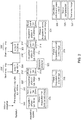
- an x-ray imaging system can be configured as an example of the operating mode presented in the following.
- An (x-ray) recording session can initially be started by actuating a recording switch.
- An initiation of actuation 300 can thus take place.
- a preheating period 302 can be provided, in which the x-ray emitter or x-ray tube is warmed prior to the application of a high voltage, preferably for a time period between 400 and 1,600 milliseconds, e.g. 800 milliseconds.
- the preheating period serves in particular to ensure reproducible radiation after a high voltage is added.
- At least two sequential exposures 304, 306 can then take place, for example, in which the x-ray radiation is active for a respective radiation period 304', 306'.
- the first radiation period 304' can be between 0 and 80 milliseconds, e.g. 40 milliseconds.
- the second radiation period can be between 0 and 500, e.g. between 0 and 200, milliseconds.
- the exposure time can in particular represent the exposure duration over which the x-ray radiation extends. Exposure is a process in which a detector medium is exposed to the x-ray radiation. For IO x-raying, the exposure time can also be between 10 and 500 milliseconds for example, in particular between 50 and 200 milliseconds.
- the x-ray sensor can be in a respective integration mode 308, 310 for multiple sequential integration periods 308', 310' in order to acquire said x-ray radiation.
- the respective integration periods 308', 310' are preferably at least as long as the associated radiation periods 304', 306'.
- Each integration phase 308, 310 is preferably followed by a readout phase 312, 314, which respectively extends over the readout period 312', 314'.
- One integration period and a subsequent readout period respectively contribute to the recording period (image acquisition) 316, 318 for one x-ray image.
- the recording period i.e. the image acquisition, in particular includes the exposure process and the subsequent readout from the sensor.
- a first x-ray image is recorded during a recording period that comprises an integration period between 10 and 100 milliseconds, e.g. 50 milliseconds, and a readout period between 5 and 50 milliseconds, e.g. 20 milliseconds.
- the individual x-ray image can then be subjected to an exposure analysis 322 by means of an exposure analyzer.
- the intensity of one or more received x-ray images is thereby evaluated in order to achieve a specified exposure quality or predetermined exposure range (intensity).
- a second individual x-ray image can then be recorded. It can, for example, be provided that a second x-ray image is recorded during a recording period that comprises an integration period between 0 and 500 milliseconds, e.g. 200 milliseconds, and a readout period between 5 and 50 milliseconds, e.g. 20 milliseconds.
- One or more dark current images can be recorded during corresponding recording periods 320, 324 before and/or after the recording of the temporally sequential x-ray images, wherein a respective integration phase and a readout phase are provided in each case here as well.
- an optimization 326 of the individual images can be carried out, in particular by offsetting said images with the dark current image or images, e.g. by performing a calculation based on the respective individual images and the dark current image.
- a motion compensation 328 can then be carried out in order to obtain ultimately a final IO x-ray image 330 by means of combination.
- a final IO x-ray image is thus the product of an x-ray imaging system and represents an intraorally created x-ray depiction.
- the smallest spatial resolution is broken up with image pixels.
- the generation proceeds through different phases as described, in particular after digitization as an unprocessed data collection (e.g. 16 bits, perhaps based on multiple exposures) to storage as a processed, filtered, (un)compressed data set with histogram compensation (e.g. 8 bits).
- an x-ray image is ultimately displayed or printed as a black/white negative 2D rendering, e.g. on a monitor or on a film.
- Reduced motion blur or a reduction of motion artifacts is achieved in a final x-ray image as described, whereby it is also possible that artifacts appear due to the processing of the image.
- a final x-ray image is thus an exposure-blended image with reduced motion blur or reduced motion artifacts.
- an x-ray imaging system can also be configured as an example of the operating mode presented in the following.
- an initiation of actuation 300 can again take place and a preheating period 302 of the x-ray tube can be provided.
- Unpulsed continuous radiation or pulsed radiation 404 over a radiation period 404' e.g. with a cycle duration between 0.1 and 10 milliseconds, can subsequently be provided.
- the x-ray sensor can record several or a large number of sequential x-ray images during respective recording periods 416, whereby the recording periods 416 in particular again comprise respective integration and readout periods.
- the recording periods 416 can in particular be between 0.1 and 10 milliseconds.
- said recording periods are preferably synchronized with the emitter.
- the individual x-ray images can be subjected to a continuous exposure analysis 422 by means of an exposure analyzer.
- the intensity of the x-ray images can thereby be evaluated, in particular in sum, in order to abort the recording of further individual x-ray images as soon as a predefined intensity is reached.
- the number of further x-ray images can additionally be determined.
Landscapes
- Health & Medical Sciences (AREA)
- Life Sciences & Earth Sciences (AREA)
- Engineering & Computer Science (AREA)
- Medical Informatics (AREA)
- Radiology & Medical Imaging (AREA)
- Molecular Biology (AREA)
- Biophysics (AREA)
- Nuclear Medicine, Radiotherapy & Molecular Imaging (AREA)
- Optics & Photonics (AREA)
- Pathology (AREA)
- Physics & Mathematics (AREA)
- Biomedical Technology (AREA)
- Heart & Thoracic Surgery (AREA)
- High Energy & Nuclear Physics (AREA)
- Surgery (AREA)
- Animal Behavior & Ethology (AREA)
- General Health & Medical Sciences (AREA)
- Public Health (AREA)
- Veterinary Medicine (AREA)
- Computer Vision & Pattern Recognition (AREA)
- Dentistry (AREA)
- Oral & Maxillofacial Surgery (AREA)
- Apparatus For Radiation Diagnosis (AREA)
Abstract
Description
- The invention relates to a dental x-ray imaging system for producing intraoral x-ray images, in particular of dental patient tissue, with the aid of an intraoral x-ray sensor, which can be placed in the oral cavity of a patient in the beam path of an, in particular handheld, x-ray emitter positioned outside the oral cavity.
- A variety of x-ray-based imaging systems are available in the field of dental radiology, whereby said imaging systems can be subdivided into extraoral and intraoral x-ray systems. Extraoral x-ray technology (EO x-raying) is typically used for two-dimensional panoramic imaging, for remote x-ray imaging, or for three-dimensional digital volume tomography (DVT). Intraoral x-ray systems (IO x-raying), on the other hand, are generally used for imaging a limited area of the jaw, for example one or more teeth.
- When using intraoral x-ray technology, the x-ray sensor, i.e. the x-ray detector or, in the case of an analog recording, the x-ray film, is placed inside the oral cavity of the patient, so that x-ray radiation can penetrate the relevant region of the jaw from outside the oral cavity and expose the x-ray sensor in the mouth. An x-ray tube serves as part of an x-ray emitter, which can be attached to a movable support arm, for example, or can also be designed as a mobile handheld device, to produce the x-ray radiation.
- On the one hand, care must be taken to ensure the proper positioning of the x-ray sensor and the x-ray emitter in relation to one another and to the jaw region to be irradiated in order to create high-quality intraoral x-ray images and thus make the best dental diagnosis possible. On the other hand, proper and coordinated setting and control of the radiation and detection parameters is important.
- Depending on the size of the patient, the jaw region, and the emitter output, the exposure time when using modern detectors for intraoral diagnostic radiology can, for example, be between 40 and 200 milliseconds. The longer this exposure time is, the greater are the influences of motionsof emitter, sensor, and patient, which adversely affect the resolution of the resulting x-ray image and can lead to motion blur or motion artifacts. Such lack of sharpness or artifacts caused by motion of the patient, the sensor and/or the emitter during the exposure can show up in the image as visible blurring.
- When using x-ray emitters with a fixedly mounted support arm, the motion of the emitter at least can be minimized, but motions of the sensor and the patient, which can lead to motion blur, remain. On the other hand, when using handheld emitters (handheld x-ray emitters), the motion of the emitter can also lead or contribute to motion blur because intraoral radiography is an expositing technique. The common use of relatively low dose outputs is an additional complicating factor when using handheld emitters. Exposure times are therefore generally longer, which further promotes undesirable motion blur and/or artifacts.
- Another problem that can occur in intraoral imaging is locally insufficient or, in the worst case, completely absent exposure of the x-ray sensor. Such exposition can in particular occur in the event of an incorrect alignment of the emitter, the sensor, and the patient tissue relative to one another. This can possibly again also be attributed to undesirable motions occurring during or even before exposure. This problem is exacerbated when handheld x-ray emitters are used. The x-rays, which are typically limited to a specific diameter by collimation, consequently reach the sensor surface only partly or perhaps not at all. Despite using the full patient dose, this can result in no usable image being produced.
- In summary, it can be stated that the recording of x-ray images for intraoral diagnostics, in particular when using handheld emitters, still has room for improvement.
- The underlying object of the invention is therefore to facilitate the creation of intraoral x-ray images, so that motion blur or motion artifacts are minimized or avoided and x-ray recordings having the highest possible precision and sharpness and showing the greatest possible number of anatomical details can be obtained.
- A further aspect of said object is to minimize or avoid x-ray exposition or, if there is exposition, at least to keep the patient dose low. It is therefore also an aspect of said object to increase the likelihood of obtaining a usable x-ray image.
- The object of the invention is achieved with the subject matter of the independent claims. Advantageous further developments of the invention are defined in the dependent claims.
- The invention provides a dental x-ray imaging system for producing an intraoral x-ray image with reduced motion blur.
- The x-ray imaging system comprises an intraoral x-ray sensor, which can be placed behind patient tissue to be irradiated inside the mouth of a patient in the beam path of an x-ray emitter positioned outside the mouth of the patient.
- The intraoral x-ray sensor is in particular embodied as a sensor (detector) having a matrix structure, which is configured to break an x-ray image projection up into pixels. The detected signal strength per pixel preferably corresponds to the locally absorbed x-ray beam energy. The x-ray imaging system can further comprise an x-ray emitter, for example embodied as a handheld device, as will be explained in more detail below.
- According to the invention, the x-ray imaging system is configured to record at least two and preferably several or even a large number of temporally sequential individual x-ray images of the patient tissue during respective exposures, wherein these individual x-ray images are in particular recorded during one recording session.
- The temporally sequential individual x-ray images are generally the result of individual exposures, whereby, as it will be discussed later, continuous radiation generated by the emitter may also be an option. It is worth mentioning that the temporally sequential individual x-ray images are in particular insufficiently exposed, i.e. fall short of a predefined exposure range or level, for example, and are therefore generally not yet used for medical diagnosis.
- The temporally sequential individual x-ray images may also not yet be further processed, so that they are still present in the form of raw data, for example, which can advantageously still be corrected with the aid of histogram compensation and/or with respect to sensor inadequacies.
- According to the invention, the x-ray imaging system is configured to create an overall x-ray image from the or some of the temporally sequential individual x-ray images such that (i) on the one hand, the respective exposures, or, more specifically, the results of the respective exposures are merged and (ii) on the other hand, motion occurring between and/or during the sequential individual x-ray images is compensated. It is thus possible to obtain an exposure-blended intraoral x-ray image with reduced motion blur.
- The obtained intraoral x-ray image combines the image information of the two or more temporally sequential individual x-ray images and is in particular sufficiently exposed, i.e. achieves a predefined exposure range, for example, and can therefore generally be used for diagnosis. In other words, the x-ray imaging system is in particular configured to merge the two or more temporally sequential individual x-ray images, which can originate from pre- and main exposures, for example, to one final intraoral x-ray image in a later step. This "summed" final IO x-ray image preferably has a predefined exposure range (intensity), which represents a compromise between radiation hygiene and sensor saturation on the one hand and the expected image quality for a reliable diagnosis on the other hand.
- The use of the invention thus advantageously avoids the long overall exposure that would certainly ensure an exposure range suitable for the diagnosis, but is sensitive to shaking and motion blur. Motion blur, which would otherwise occur during long overall exposure due to motion of focus, patient, and/or detector and is expressed in "smearing" at least in parts of the x-ray image, can thus successfully be minimized or avoided. The advantage of reduced motion blur comes into play particularly for handheld x-ray emitters, but it is generally applicable as a basic principle.
- Motion compensation is carried out in the course of or prior to merging the temporally sequential individual x-ray images. Motion, for example of focus, patient, and/or detector, which occurs between and/or during the individual x-ray images, is thus compensated. In this way, effects of the motion, which would otherwise lead to motion blur or motion artifacts, can advantageously be reduced or avoided. This also means that the likelihood of an IO x-ray image usable for diagnosis, in particular in the case of handheld emitters, is increased. Consequently, there is no need for further x-ray images, which in turn also reduces the radiation exposure for patients.
- Motion compensation can in particular be achieved by using a motion compensator. As will be explained in more detail further below, a hardware solution can in principle be provided to bring about an oppositely-directed motion, or motion compensation preferably takes place in a later step, i.e. after recording the individual x-ray images. In this case, a compensation of the motion in particular refers to the compensation of the effect of a motion on the individual x-ray images.
- As already mentioned, the temporally sequential individual x-ray images can be available unprocessed, as raw sensor data. However, the x-ray imaging system preferably comprises an image optimizer that is configured to optimize and correct the individual images.
- The image optimizer can in particular be configured to correct the individual images with respect to sensor inadequacies. To do this, the x-ray imaging system can be configured to record a dark current image in which the sensor is not exposed with x-ray radiation, for example prior to the first individual image and/or after the last individual image. The image optimizer can then use one or more dark current images to optimize the or at least one of the sequential x-ray images possibly still present in the form of raw data and/or the overall x-ray image of the patient tissue.
- To do this, the image optimizer can in particular be configured to perform a calculation based on x-ray sensor signal values associated with pixels of a dark current image on the one hand, and x-ray sensor signal values associated with pixels of one of the sequential x-ray images and/or of the overall x-ray image of the patient tissue on the other hand. In other words, the image optimizer can be configured to offset x-ray sensor signal values associated with pixels of a dark current image with x-ray sensor signal values associated with pixels of the sequential x-ray image and/or of the overall x-ray.
- The image optimizer can additionally be configured to perform further corrections, for example a histogram compensation and/or a linearization of the brightness values associated with the pixels.
- An image optimizer included in the x-ray imaging system can be embodied as a hardware component, which preferably contains an FPGA module or functionally identical or similar module or is embodied as such. On the other hand, it can also be provided that the image optimizer or parts thereof are embodied as a computer program, wherein the program includes instructions that, when executed by a computer, cause said computer to optimize at least one of the temporally sequential individual x-ray images and/or the overall x-ray image of the patient tissue, in particular by means of a dark current image.
- The x-ray imaging system can further comprise an image selector, wherein the image selector is configured to select or reject specific x-ray images from the or some of the sequential individual x-ray images.
- The image selector can in particular be configured to evaluate the or some of the sequential individual x-ray images using predefined criteria in order to select from among them suitable, in particular sufficiently congruent, x-ray images or reject unsuitable, in particular overly incongruent x-ray images.
- By selecting and/or rejecting x-ray images, a motion compensation can be achieved. Individual images can, in a sense, be "shaken in" until a certain quality measure is achieved. An image selector configured in this way is particularly suitable when several or a large number of temporally sequential individual x-ray images are recorded.
- A minimum degree of congruence or incongruence can be used as a criterion for selecting and/or rejecting individual x-ray images. The brightness values, for example, that are associated with the, or for example several, uniformly or statistically distributed pixels, can be used for this purpose.
- The image selector can be embodied as a hardware component, preferably comprising or embodied as an FPGA module or functionally identical or similar module. It can also be provided that the image selector or parts thereof are embodied as a computer program, wherein the program includes instructions that, when executed by a computer, cause said computer to select and/or reject individual x-ray images.
- The x-ray imaging system further preferably comprises a motion detector, wherein said motion detector is configured to detect motion occurring between and/or during the or some of the sequential individual x-ray images.
- Within the context of this application, detection can generally be the mere determination of the existence of a motion. A motion detector that detects the existence or absence of a motion can be connected to an image selector as described above, for example, and provide a criterion for selection or rejection to said image selector.
- Preferably, however, beyond the mere determination of the existence of a motion, detection also includes a quantification of the motion. In one advantageous design, the motion detector is configured to detect the or components of the motion trajectory. Such a detection can already take place during the exposure and/or be reconstructed in a later step.
- With regard to a subsequent reconstruction, the motion detector can be configured to allocate pixels of temporally sequential individual x-ray images to an identical section of the patient tissue in order thereby to detect motion occurring between the sequential exposure times. In other words, knowledge can be obtained of a motion trajectory by evaluating individual images produced over one or specific exposure times. The motion detector is therefore able, for example, to detect the trajectory of a relative motion between the x-ray emitter, the patient tissue and/or the x-ray sensor, in particular the relative trajectory between the image of the patient tissue in the sensor plane and the x-ray sensor.
- A motion detector included in the x-ray imaging system can be embodied as a hardware component, preferably embodied as or comprising an acceleration sensor and/or an FPGA module or functionally identical or similar module. If the motion detector is embodied as a hardware component, in particular comprising an acceleration sensor, motion detection can already take place during exposure. It can also be provided that the motion detector comprises multiple acceleration sensors, wherein one acceleration sensor is, for example, associated with the x-ray emitter in order to detect the motion of said emitter, and one or more further acceleration sensors are associated with the x-ray sensor and/or the patient in order to detect the respective motion of said sensor or said patient. The motion detector can therefore also be able to detect absolute motion trajectories, for example, and, preferably, convert them to relative motion trajectories.
- It can also be provided that the motion detector or components thereof are embodied as a computer program, wherein the program includes instructions that, when executed by a computer, cause said computer to detect a motion. In this case, or if the motion detector comprises an FPGA module or functionally identical or similar module, a reconstruction of a motion can be provided in a later step. A combination of such a design with one or more acceleration sensors is possible as well.
- A detected motion, in particular a detected motion trajectory, can generally include the time profile of a position and/or include the time profile of an orientation. The motion detector can thus also be configured to, for example, detect the time profile of the tilting of the sensor plane with respect to the central beam.
- The x-ray imaging system furthermore preferably comprises a motion compensator, wherein said motion compensator is configured to compensate a motion and thereby preferably harmonize the or some of the sequential individual x-ray images to one another. As discussed above, in the context of this application, the compensation of a motion is in particular the compensation of an effect of the motion on the individual x-ray images.
- The motion to be compensated is in particular a motion detected by means of a motion detector. Specifically, the motion compensator can, for example, be configured to align the pixels (e.g. achieve congruence) of the temporally sequential individual x-ray images allocated by a motion detector to an identical section of the patient tissue by means of image transformation, in order to harmonize said x-ray images with one another.
- It is possible, for example, for the respective motion of the emitter relative to the patient and the sensor to be determined via image recognition algorithms, in particular by means of the motion detector. By means of the motion compensator, one, several or every individual temporally sequential individual x-ray image can then be corrected according to the motion via image processing methods. An image processing method can include one or more geometric image transformations, e.g. translation, rotation, scaling, distortion or combinations thereof. It is possible, for example, for a plurality of first positions on a first individual x-ray image and a plurality of second positions on a second individual x-ray image to be identified as corresponding to one another with respect to the imaged patient tissue, and for at least one of the individual x-ray images to be transformed in such a way that the first and second positions are aligned (e.g. transformed such to be congruent).
- In this way, in particular when a motion trajectory is known, motions or motion artifacts can be removed from one or more individual x-ray images by using an appropriate method.
- A motion compensator included in the x-ray imaging system can be embodied as a hardware component, preferably comprising an FPGA module or functionally identical or similar module. In general, a hardware solution in which the focus and/or the detector move in opposite directions is possible. The motion compensator can, however, also be embodied as a computer program, which includes instructions that, when executed by a computer, cause said computer to compensate the motion.
- The x-ray imaging system further preferably comprises an image combiner that is configured to combine the or some of the sequential, in particular harmonized, individual x-ray images to an overall x-ray image such that the respective exposures are merged.
- The image combiner can in particular be configured to offset x-ray sensor signal values, which are associated with pixels of the temporally sequential, in particular harmonized, individual x-ray images, against one another in order to combine said x-ray images or parts thereof into an overall x-ray image. For example, the image combiner can be configured to perform a calculation based on x-ray sensor signal values, which are associated with pixels of the temporally sequential, in particular harmonized, individual x-ray images. Specifically, x-ray sensor signal values can be offset against one another by means of a weighted sum method. The overall x-ray image is then, in particular, an exposure-blended intraoral x-ray image with reduced motion blur or motion artifacts, which can be provided for diagnosis.
- When the individual x-ray images are combined to the overall x-ray image, in particular by offsetting the signal values (e.g. performing calculations based on these values), the information about the patient tissue displayed by each individual x-ray images preferably is preserved and/or contributes to the overall x-ray image. In other words, the image contents of the individual x-ray images are combined. The individual x-ray images are therefore preferably used in their entirety. For example, all the pixels of the individual x-ray images or at least contiguous two-dimensional regions with a number of directly adjacent pixels (e.g. more than 10 percent or more than 50 percent or more than 90 percent of the total pixels) of the individual x-ray images can be included in the overall x-ray image. In particular analyzing only a plurality of individual pixels of a sensor or an individual x-ray image during or after an exposure may be unnecessary.
- The image combiner can be embodied as a hardware component, preferably comprising an FPGA module or functionally identical or similar module, and/or embodied as a computer program, which includes instructions that, when executed by a computer, cause said computer to combine the respective individual x-ray images to the overall x-ray image.
- A final x-ray image can accordingly be calculated from multiple individual images. The individual images originate in particular from one recording session. A recording session can, for example, be started by pressing a recording switch. Radiation can be subsequently generated in an automated manner and x-ray image information can be acquired. A final IO x-ray image can then be created for each recording session, in particular by means of the image optimizer, image selector, motion detector, motion compensator, image combiner or at least some of these components, which can also be integrated or consolidated into one or more common modules. An image processing system can, for example, comprise several or all of said components.
- Since, as described, two, multiple or even many sequential individual x-ray images can be recorded using the x-ray imaging system, the x-ray imaging system is preferably configured to record the individual x-ray images quickly. The IO x-ray sensor is therefore preferably embodied as a rapid sensor.
- The x-ray imaging system is in particular configured to respectively record the one or more sequential individual x-ray images in a time span that is less than 500 milliseconds, in particular less than 250 milliseconds, in particular less than 100 milliseconds, in particular less than 50 milliseconds, in particular less than 25 milliseconds, in particular less than 10 milliseconds, in particular less than 2.5 milliseconds, in particular less than 0.25 milliseconds, wherein multiple sequential individual x-ray images can in particular be recorded in time spans of different lengths. For example, the time span of an initially recorded x-ray image can be less than the time span of a subsequently recorded individual x-ray image.
- The time span for the recording or acquisition of an individual x-ray image can in particular comprise an integration phase and a readout phase of the x-ray sensor. The x-ray imaging system is typically configured to record more individual x-ray images the shorter the time spans between the individual images.
- The x-ray imaging system can therefore also be configured to record a series of temporally sequential individual x-ray images of the patient tissue, in particular record at least 2, in particular at least 3, in particular at least 10, in particular at least 100, in particular at least 1,000, in particular at least 10,000 temporally sequential individual x-ray images of the patient tissue.
- The x-ray emitter, which emits x-ray radiation for recording the temporally sequential individual x-ray images, can operate in single operation, continuous operation, or pulsed operation. The x-ray imaging system can therefore be configured to record the temporally sequential individual x-ray images in a single operation, continuous operation, or pulsed operation of the x-ray emitter.
- It can be provided that an individual x-ray image is recorded in a recording period between 10 and 100 milliseconds, for example, and that, for this purpose, the x-ray emitter emits radiation in single operation over a radiation period that is in particular of equal or lesser length than the recording period. After a time span, one further individual x-ray image, for example, can then be recorded in a recording period, e.g. between 0 and 500 milliseconds, whereby, for this purpose, the x-ray emitter again emits radiation in single operation over a radiation period that is in particular of equal or lesser length than the recording period.
- It can, however, also be provided that, for example, at least 3, in particular at least 10, in particular at least 100, in particular at least 1,000, in particular at least 10,000 individual x-ray images are recorded in time spans between 0.1 and 10 milliseconds, and that the x-ray emitter operates in continuous operation or in a pulsed operation synchronous to said recording.
- The exposure times for handheld x-ray emitters are generally longer due to the lower emitter output. In particular for handheld emitters, but also in general, the time period from the start of the first to the end of the last shot can be at least 0.25 seconds, in particular at least 0.5 seconds; it can, however, also be significantly more. This applies both in the case that a few longer recordings are carried out and in the case that several shorter recordings are carried out. X-ray recordings with radiation times that suggest that motion artifacts may occur should then be divided into individual recordings, which are then offset (e.g. calculated together). The x-ray imaging system can therefore generally be configured to record the temporally sequential individual x-ray images (in particular all of those) during a total time period of at least 0.25 seconds, in particular during a total time period of at least 0.5 seconds.
- The x-ray imaging system can furthermore comprise an exposure analyzer, which is configured to analyze the exposure of at least one of the temporally sequential x-ray images.
- The x-ray imaging system preferably also comprises a control device, which is configured to control the x-ray sensor and/or the x-ray emitter based on the analyzed exposure, preferably in such a way that the exposure, in particular the recording period (duration), of a further of the sequential individual x-ray images and/or the number of such further images is such that the overall x-ray image achieves a predetermined exposure range (intensity and/or level) .
- The x-ray imaging system can in particular be configured, based on the analyzed exposure, to determine whether the exposure has fallen short of a predetermined exposure range, and, if the exposure has fallen short of said exposure range, to control the x-ray sensor and/or the x-ray emitter in such a way that a) the acquisition of further temporally sequential individual x-ray images is continued and/or b) the predetermined exposure range is achieved with the subsequent individual x-ray image.
- The x-ray imaging system can also be configured, based on the analyzed exposure, to determine whether the exposure has fallen short of a predetermined minimum exposure range, and, if the exposure has fallen short of said minimum exposure range, to control the x-ray sensor and/or the x-ray emitter in such a way that the acquisition of further temporally sequential individual x-ray images is ended. An early termination, in particular in the event of incorrect or inadequate positioning of the x-ray sensor and/or the x-ray emitter, can thus take place. This makes it possible to reduce the radiation exposure of the patient.
- The x-ray imaging system can also be configured, based on the analyzed exposure of at least one, several or all of the thus far acquired individual x-ray images, to determine whether the exposure for this recording session has achieved or exceeded a predetermined exposure range, and, if the exposure has achieved or exceeded said exposure range, to control the x-ray sensor and/or the x-ray emitter in such a way that the acquisition of further temporally sequential individual x-ray images is ended in order to avoid unnecessary radiation exposure.
- If an exposure analyzer is used, it can, for example, be provided that a first individual x-ray image (pre-exposure image) is recorded with a fixed time span, e.g. between 10 and 100 milliseconds, the exposure of said image is analyzed, and a second x-ray image (main exposure image) is subsequently recorded with a variable time span, e.g. between 0 and 500 milliseconds, wherein the variable time span depends on the exposure range of the first x-ray image.
- The exposure analyzer can, however, also be configured to analyze the exposure continuously, e.g. during the recording of an individual x-ray image or during the recording of a series of individual x-ray images, for example when at least 3, in particular at least 10, in particular at least 100, in particular at least 1,000, in particular at least 10,000 x-ray images are recorded. The exposure analyzer can then analyze the exposure of multiple sequential individual x-ray images of the series, for example, and end the recording of further series images when a predefined exposure range is reached.
- The exposure analyzer and the control device can therefore in particular form a unit for automatic exposure control (AEC). As described, for example at least two recordings (pre-and main exposure) can be created, which are added together in a later step to form one IO x-ray image. The two or more temporally sequential individual x-ray images can thus be used in a synergistic manner, both for the compensation of a motion (or motion artifacts) and for exposure control.
- When an exposure analyzer is used to end further recordings, the x-ray imaging system can further be configured such that a forced break, in particular for repositioning the x-ray sensor and/or the x-ray emitter, occurs after the recording of further temporally sequential individual x-ray images is ended, wherein the forced break is in particular at least 0.5 seconds.
- When an exposure analyzer is used to end further recordings, communication between the recording system and the emitter can serve to terminate the recording as soon as a critical number of individual images have been locally insufficiently exposed.
- The x-ray imaging system, in particular the control device, can also be configured to synchronize a pulsed operation of the x-ray emitter with the x-ray image recording by the x-ray sensor. A connection between the sensor (recording system) and the emitter can be further provided for the purpose of synchronization, both for a continuous operation and for a pulsed operation. However, a connection between the sensor and the emitter may also be omitted (calibration recording can measure pulsed operation).
- The exposure analyzer and/or the control device can again be embodied as a hardware component, preferably comprising an FPGA module or functionally identical or similar module and/or as a computer program, which includes instructions that, when executed by a computer, cause said computer to analyze the exposure.
- The x-ray imaging system can further comprise the x-ray emitter that can be positioned outside the mouth of the patient in the beam path of which the intraoral x-ray sensor can be placed behind the patient tissue to be irradiated inside the mouth of the patient.
- A holding system, which can be fastened or adapted to the x-ray emitter and/or the x-ray sensor in order to align the x-ray emitter in relation to the x-ray sensor, can be included as well. The holding system serves in particular as an adjustment aid for the x-ray emitter.
- The invention further relates to a dental x-ray imaging method for producing an intraoral x-ray image with reduced motion blur, in particular by means of an x-ray imaging system as described above, wherein an intraoral x-ray sensor is placed behind patient tissue to be irradiated inside the mouth of a patient in the beam path of an, in particular hand-held, x-ray emitter positioned outside the mouth of the patient, and wherein two or more temporally sequential individual x-ray images of the patient tissue are recorded during respective exposures, and wherein an overall x-ray image is created from the or some of the temporally sequential individual x-ray images such that, on the one hand, the respective exposures are merged and, on the other hand, motion occurring between the sequential individual x-ray images is compensated so as to produce an exposure-blended intraoral x-ray image with reduced motion blur.
- The invention further relates to a method for producing an x-ray image with reduced motion blur on an x-ray phantom, in particular by means of an x-ray imaging system as described above, wherein an x-ray phantom having a phantom structure to be irradiated is provided, which in particular simulates dental patient tissue, and wherein an intraoral x-ray sensor is placed behind the phantom structure to be irradiated in the beam path of an, in particular hand-held, x-ray emitter, and wherein two or more temporally sequential individual x-ray images of the phantom structure are recorded during respective exposures, and wherein an overall x-ray image is created from the or some of the temporally sequential individual x-ray images such that, on the one hand, the respective exposures are merged and, on the other hand, motion occurring between the exposures is compensated so as to produce an exposure-blended x-ray image with reduced motion blur.
- The invention further relates to a method for the post-processing of temporally sequential intraoral individual x-ray images for producing an exposure-blended intraoral x-ray image with reduced motion blur, in particular by means of an x-ray imaging system as described above, wherein two or more temporally sequential intraoral individual x-ray images are read from a memory and wherein an overall x-ray image is created from the or some of the temporally sequential individual x-ray images such that, on the one hand, the respective exposures are merged and, on the other hand, motion occurring between the sequential x-ray images is compensated so as to produce an exposure-blended x-ray image with reduced motion blur.
- The invention further also relates to a computer program for a dental x-ray imaging system as described above, or for a dental x-ray imaging method as described above, or for a method for producing an x-ray image on an x-ray phantom as described above, or for a method for the post-processing of intraoral individual x-ray images as described above, comprising: instructions that, when executed by a computer, cause said computer to record two or more temporally sequential individual x-ray images of patient tissue or a phantom structure during respective exposures and/or read said images from a memory, and/or instructions that, when executed by a computer, cause said computer to analyze the exposure of at least one of the sequential x-ray images, and/or instructions that, when executed by the computer, cause said computer to optimize the or at least one of the sequential x-ray images and/or the overall x-ray image by means of one or more dark current images, and/or instructions that, when executed by the computer, cause said computer to select or reject specific individual x-ray images from the or some of the sequential individual x-ray images, and/or instructions that, when executed by a computer, cause said computer to detect motion occurring between the or some of the sequential individual x-ray images, and/or instructions that, when executed by a computer, cause said computer to harmonize the or some of the sequential individual x-ray images with one another such that the motion is compensated, and/or instructions that, when executed by a computer, cause said computer to combine the or some of the sequential, in particular harmonized, individual x-ray images to one overall x-ray image.
- Lastly, the invention relates to a data carrier or data signal comprising a computer program as described above.
- The figures show:
- Fig. 1
- a block diagram of an example of a dental x-ray imaging system,
- Fig. 2
- a time diagram of a first example of an operating mode of a dental x-ray imaging system,
- Fig. 3
- a time diagram of a second example of an operating mode of a dental x-ray imaging system.
- With reference to
Fig. 1 , anx-ray imaging system 100 can comprise an intraorally placedx-ray sensor 110, which is configured to detect x-rays of an extraorally placedx-ray emitter 120. Before impinging on thex-ray sensor 110, the x-rays pass through an intraoral recording region of thepatient 130, so that the x-ray sensor is capable of recording an x-ray image of the patient tissue. Asensor holding system 210 can be fixedly attachable to thex-ray sensor 110. Thesensor holding system 210 can furthermore be securable to the patient, in particular to the mouth of the patient, so that thex-ray sensor 110 is substantially fixed via theholding system 210 in relation to thepatient tissue 130 to be irradiated. The holdingsystem 210 can further comprise a positioning aid for thex-ray emitter 120, which preferably projects from the mouth of the patient and forms a, for example, ring-shaped structure, e.g. with a respective contact surface, to which thex-ray emitter 120 can be guided, in particular with its tube, in order to ensure a correct alignment of the emerging x-rays. - In the depicted example, the
x-ray sensor 110 is part of an x-ray sensor unit 105 (which is sometimes also referred to as x-ray sensor for short) having a housing, which can be placed inside the mouth of the patient and can contain further components. Anx-ray sensor unit 105 can comprise asensor control 112, for example, which can be configured to control the sensor, in particular depending on predefined criteria, in such a way that x-rays are acquired (integration phase) and/or that an x-ray image is output in the form of x-ray sensor signal values (readout phase). Individual x-ray images acquired by the x-ray sensor can then be temporarily stored in animage memory 114. Anx-ray sensor unit 105 can further comprise apower unit 116, which supplies other components, in particular thesensor control 112, theimage memory 114 and/or thex-ray sensor 110, with electrical energy. A transmitting/receivingunit 118, which allows an in particular wireless transmission of x-ray images, can be provided as well. The above-described components can, however, also be provided outside thex-ray sensor unit 105 and may optionally form independent units or be included in another unit. An option, for example, is anexternal interface 132, for example, which is used between the sensor and the emitter unit, i.e. is physically decoupled from these two components. When appropriate, the sensor can then be made smaller. This may provide advantages in terms of space and cost. In order to ensure the above-described transmission, such an external interface can be connected to aninternal interface 134 by means of a cable or wirelessly. - In the depicted example, the
x-ray emitter 120 is part of an x-ray emitter unit 115 (which is sometimes also referred to as x-ray emitter for short) which can again comprise a separate housing, in which further components can be located. Anx-ray emitter unit 115 can comprise an emitter control 122, for example, which can be configured to activate or deactivate the emitter. The emitter control 122 can be connected to thesensor control 112. Thex-ray emitter unit 115 can further comprise animage memory 124. Thex-ray imaging system 100 can be configured to transmit individual x-ray images from theimage memory 114 of thesensor unit 105 to theimage memory 124 of theemitter unit 115. For this purpose, a connection of the two units can be provided via a cable, for example, or transmission can take place by means of the transmitting/receivingunit 118. Theemitter unit 115 preferably further comprises apower unit 126, which supplies other components, in particular those described above or below, with electrical energy. To control thex-ray emitter 120 and/or to set radiation parameters, theemitter unit 115 can also comprise auser interface 127. In one preferred embodiment, theemitter unit 115 is embodied as ahandheld x-ray emitter 250. - The
x-ray imaging system 100, in particular thex-ray emitter unit 115, can furthermore comprise animage evaluation unit 220 that may be configured for rapid image evaluation and may have anexposure analyzer 190. The exposure range of an individual x-ray image, which is temporarily stored in theimage memory 124, for example, can be analyzed by means of theexposure analyzer 190. Depending on the exposure range, a control signal to control the x-ray emitter such that the exposure range of further individual x-ray images and/or the number of further x-ray images is affected can be sent to the emitter control 122. The control signal can also be an on/off signal to activate or deactivate the emitter. - The
x-ray imaging system 100, in particular thex-ray emitter unit 115, can also include one or moreimage processing units image optimizer 140, animage selector 150, a motion detector 160, a motion compensator 170, and/or an image combiner 180. To optimize individual x-ray images present in theimage memory 124 as raw data, for example by means of dark current images, theimage processing unit 230 can, for example, comprise animage optimizer 140. To compensate a motion, in particular by means of image transformations, saidimage processing unit 230 can further comprise a motion detector 160 and/or motion compensator 170. To combine multiple individual x-ray images after compensation of the motion by merging the exposures to one final exposure-blended IO x-ray image with reduced motion blur, saidimage processing unit 230 can further comprise an image combiner 180. An image processing unit thus receives analog or digital x-ray image information and processes said information, e.g. via image optimization. The information can furthermore be archived and/or displayed. - A final IO x-ray image can, for example, be displayed directly by means of an
image display unit 128, which can be part of the emitter unit 115 (instant image). Theimage processing unit 230 for producing the final IO x-ray image for direct display can, for example, work with limited resolution. Animage processing unit 230' for producing the final IO x-ray image for external display, for example on acomputer 240 having animage memory 242, animage display unit 244, and, if appropriate, auser interface 246, can be provided as well. - The components described above as a part of the
x-ray emitter unit 115 can also be provided outside thex-ray emitter unit 115 and may optionally form independent units or be included in another unit. Animage processing unit 230' can, for example, also be embodied as part of thecomputer 240. - In the context of this application, the x-ray sensor that can be placed in the mouth is generally to be understood as an
x-ray sensor 110 in the narrower sense. In the broader sense, however, the x-ray sensor can also be placeable in the mouth with the housing and, if applicable, further components (x-ray sensor unit 105). Correspondingly, the x-ray emitter is generally to be understood as theemitter 120 in the narrower sense, i.e. for example an x-ray tube or a component comprising an x-ray tube. In a broader sense however, the x-ray emitter can also be positioned outside the mouth with the housing and, if applicable, further components (x-ray emitter unit 115, handheld x-ray emitter 250) . - With reference to
Fig. 2 , an x-ray imaging system can be configured as an example of the operating mode presented in the following. An (x-ray) recording session can initially be started by actuating a recording switch. An initiation ofactuation 300 can thus take place. A preheatingperiod 302 can be provided, in which the x-ray emitter or x-ray tube is warmed prior to the application of a high voltage, preferably for a time period between 400 and 1,600 milliseconds, e.g. 800 milliseconds. The preheating period serves in particular to ensure reproducible radiation after a high voltage is added. At least twosequential exposures - During the emission of x-ray radiation, the x-ray sensor can be in a
respective integration mode integration phase readout phase - The individual x-ray image can then be subjected to an
exposure analysis 322 by means of an exposure analyzer. The intensity of one or more received x-ray images is thereby evaluated in order to achieve a specified exposure quality or predetermined exposure range (intensity). Depending on such evaluation, a second individual x-ray image can then be recorded. It can, for example, be provided that a second x-ray image is recorded during a recording period that comprises an integration period between 0 and 500 milliseconds, e.g. 200 milliseconds, and a readout period between 5 and 50 milliseconds, e.g. 20 milliseconds. - One or more dark current images can be recorded during
corresponding recording periods - After at least two temporally sequential x-ray images have been recorded, an
optimization 326 of the individual images can be carried out, in particular by offsetting said images with the dark current image or images, e.g. by performing a calculation based on the respective individual images and the dark current image. Amotion compensation 328 can then be carried out in order to obtain ultimately a finalIO x-ray image 330 by means of combination. - A final IO x-ray image is thus the product of an x-ray imaging system and represents an intraorally created x-ray depiction. Just as for the individual temporally sequential x-ray images, the smallest spatial resolution is broken up with image pixels. The generation proceeds through different phases as described, in particular after digitization as an unprocessed data collection (e.g. 16 bits, perhaps based on multiple exposures) to storage as a processed, filtered, (un)compressed data set with histogram compensation (e.g. 8 bits). From the user's point of view, an x-ray image is ultimately displayed or printed as a black/white negative 2D rendering, e.g. on a monitor or on a film. Reduced motion blur or a reduction of motion artifacts is achieved in a final x-ray image as described, whereby it is also possible that artifacts appear due to the processing of the image. A final x-ray image is thus an exposure-blended image with reduced motion blur or reduced motion artifacts.
- In summary, therefore, after the initiation of a recording session, in particular by actuating a switch, radiation is subsequently generated in an automated manner and x-ray image information is acquired. One final IO x-ray image can in particular be created per recording session.
- With reference to
Fig. 3 , an x-ray imaging system can also be configured as an example of the operating mode presented in the following. To begin with, an initiation ofactuation 300 can again take place and apreheating period 302 of the x-ray tube can be provided. Unpulsed continuous radiation orpulsed radiation 404 over a radiation period 404', e.g. with a cycle duration between 0.1 and 10 milliseconds, can subsequently be provided. - During the radiation period 404', the x-ray sensor can record several or a large number of sequential x-ray images during respective recording periods 416, whereby the recording periods 416 in particular again comprise respective integration and readout periods. In this operating mode, the recording periods 416 can in particular be between 0.1 and 10 milliseconds. During a pulsed operation of the emitter, said recording periods are preferably synchronized with the emitter.
- The individual x-ray images can be subjected to a
continuous exposure analysis 422 by means of an exposure analyzer. The intensity of the x-ray images can thereby be evaluated, in particular in sum, in order to abort the recording of further individual x-ray images as soon as a predefined intensity is reached. Depending on the exposure range, the number of further x-ray images can additionally be determined. - After a number of temporally sequential individual x-ray images have been recorded, an
optimization 326 of the individual images, amotion compensation 328, and ultimately the production of a finalIO x-ray image 330 by means of combination can again be carried out. - To the person skilled in the art it is obvious that the above-described embodiments are only examples and the invention is not limited to them, but can instead be varied in a multitude of ways without departing from the scope of protection of the claims. It is furthermore obvious that, independent of whether they are disclosed in the description, the claims, the figures, or otherwise, the features also individually define essential components of the invention, even if they are jointly described alongside other features, and can thus be regarded as being disclosed independently of one another. The description of features of one design example also respectively applies to the other design examples.
-
- 100
- x-ray imaging system
- 105
- x-ray sensor unit
- 110
- intraoral x-ray sensor
- 112
- sensor control
- 114
- image memory of the sensor unit
- 115
- x-ray emitter unit
- 116
- power unit for the sensor unit
- 118
- transmitting/receiving unit
- 120
- x-ray emitter
- 122
- emitter control
- 124
- image memory of the emitter unit
- 126
- power unit for the emitter unit
- 127
- user interface
- 128
- image display unit
- 130
- patient tissue to be irradiated
- 132
- external interface
- 134
- internal interface
- 140
- image optimizer
- 150
- image selector
- 160
- motion detector
- 170
- motion compensator
- 180
- image combiner
- 190
- exposure analyzer
- 200
- control device
- 210
- holding system
- 220
- image evaluation unit
- 230, 230'
- image processing unit
- 240
- computer
- 242
- image memory of the computer
- 244
- image display unit of the computer
- 246
- user interface of the computer
- 250
- handheld x-ray emitter
- 300
- initiation of actuation
- 302
- preheating period
- 304, 306, 404
- exposure
- 304', 306', 404'
- radiation period
- 308, 310
- integration mode
- 308', 310'
- integration period
- 312, 314
- readout mode
- 312', 314'
- readout period
- 316, 318, 324, 416
- recording period
- 322, 422
- exposure analysis
- 326
- optimization
- 328
- motion compensation
- 330
- final IO x-ray images
Claims (15)
- Dental x-ray imaging system (100) for producing an intraoral x-ray image with reduced motion blur comprising:an intraoral x-ray sensor (110, 105), which can be placed inside the mouth of a patient, in the beam path of an x-ray emitter (120, 115, 250) positioned outside the mouth of the patient, and behind patient tissue (130) to be irradiated,wherein the x-ray imaging system (100) is configured to record two or more temporally sequential individual x-ray images of the patient tissue (130) during respective exposures in a recording session, andwherein the x-ray imaging system (100) is configured to create an overall x-ray image from the or some of the temporally sequential individual x-ray images such that, on the one hand, the results of the respective exposures are merged and, on the other hand, a motion occurring between and/or during the sequential individual x-ray images is compensated so as to produce an exposure-blended intraoral x-ray image with reduced motion blur.
- Dental x-ray imaging system according to Claim 1,wherein an image optimizer (140) is included, which is configured to optimize the or at least one of the sequential individual x-ray images and/or the overall x-ray image of the patient tissue (130) by means of one or more dark current images, and/orwherein an image selector (150) is included, which is configured to select or reject specific individual x-ray images from the or some of the sequential individual x-ray images, and/orwherein a motion detector (160) is included, which is configured to detect a motion occurring between and/or during the or some of the sequential individual x-ray images, and/orwherein a motion compensator (170) is included, which is configured to harmonize the or some of the sequential individual x-ray images with one another such that the motion is compensated, and/orwherein an image combiner (180) is included, which is configured to combine the or some of the sequential, in particular harmonized, x-ray images to the overall x-ray image such that the results of the respective individual exposures are merged.
- Dental x-ray imaging system according to Claim 1 or 2,
wherein the x-ray imaging system (100) is configured to record the or at least one of the sequential individual x-ray images during a time span that is less than 250 milliseconds, in particular less than 25 milliseconds, in particular less than 2.5 milliseconds, in particular less than 0.25 milliseconds. - Dental x-ray imaging system according to any one of Claims 1 to 3,wherein the x-ray imaging system (100) is configured to record a series of temporally sequential individual x-ray images of the patient tissue (130), in particular at least 2, in particular at least 10, in particular at least 100, in particular at least 1,000 temporally sequential individual x-ray images of the patient tissue (130), and/orwherein the x-ray imaging system (100) is configured to record the temporally sequential individual x-ray images during a pulsed operation of the x-ray emitter.
- Dental x-ray imaging system according to any one of Claims 1 to 4,wherein an exposure analyzer (190) is included, which is configured to analyze the result of the exposure of at least one, several or all of the thus far acquired temporally sequential individual x-ray images, andwherein a control device (200) is included, which is configured to control the x-ray sensor and/or the x-ray emitter based on the analyzed result of the exposure, in particular in such a way that the exposure of a further of the sequential individual x-ray images and/or the number of said further images is such that the overall x-ray image achieves a predetermined exposure range.
- Dental x-ray imaging system according to Claim 5,wherein, the x-ray imaging system (100) is configured to determine, based on the analyzed result of the exposure of at least one, several or all of the thus far acquired individual x-ray images, whether the exposure for this recording session has fallen short of a predetermined exposure range, and, if the exposure has fallen short of said exposure range, to control the x-ray sensor and/or the x-ray emitter in such a way that a) the acquisition of further temporally sequential individual x-ray images is continued and/or b) the subsequent individual x-ray image achieves the predetermined exposure range, and/orwherein the x-ray imaging system (100) is configured, based on the analyzed exposure of at least one, several or all of the thus far acquired individual x-ray images, to determine whether the exposure for this recording session has fallen short of a predetermined minimum exposure range, and, if the exposure has fallen short of said minimum exposure range, to control the x-ray sensor and/or the x-ray emitter in such a way that the acquisition of further temporally sequential individual x-ray images is ended in order to avoid unnecessary radiation exposure and/orwherein the x-ray imaging system (100) is configured, based on the analyzed exposure of at least one, several or all of the thus far acquired individual x-ray images, to determine whether the exposure for this recording session has achieved or exceeded a predetermined exposure range, and, if the exposure has achieved or exceeded said exposure range, to control the x-ray sensor and/or the x-ray emitter in such a way that the acquisition of further temporally sequential individual x-ray images is ended in order to avoid unnecessary radiation exposure.
- Dental x-ray imaging system according to any one of Claims 1 to 6,wherein the image optimizer (140) is configured to perform a calculation based on both x-ray sensor signal values associated with pixels of a dark current image and x-ray sensor signal values associated with pixels of one of the sequential x-ray images and/or the overall x-ray image of the patient tissue in order to optimize the x-ray image, and/orwherein the image selector (150) is configured to evaluate the or some of the sequential individual x-ray images using predefined criteria in order to select from among them suitable, in particular sufficiently congruent, individual x-ray images or reject unsuitable, in particular overly incongruent individual x-ray images, and/orwherein the motion detector (160) is configured to allocate pixels of temporally sequential individual x-ray images to a substantially identical section of the patient tissue in order to detect the motion occurring between and/or during the sequential individual x-ray images, and/orwherein the motion compensator (170) is configured to align, particularly bring to congruence, the pixels of the temporally sequential individual x-ray images allocated to the substantially identical section of the patient tissue by means of image transformation, in order to harmonize these x-ray images with one another and/orwherein the image combiner (180) is configured to perform a calculation based on x-ray sensor signal values of corresponding pixels of the temporally sequential, in particular harmonized, individual x-ray images in order to combine these individual x-ray images to the overall x-ray image.
- Dental x-ray imaging system according to any one of Claims 1 to 7,wherein the exposure analyzer (190) is embodied as a computer program, which includes instructions that, when executed by a computer, cause said computer to analyze the result of the exposure, and/orwherein the image optimizer (140) is embodied as a computer program, which includes instructions that, when executed by a computer, cause said computer to optimize the individual x-ray images and/or the overall x-ray image of the patient tissue by means of dark current compensation, and/orwherein the image selector (150) is embodied as a computer program, which includes instructions that, when executed by a computer, cause said computer to select or reject individual x-ray images, and/orwherein the motion detector (160) is embodied as a computer program, which includes instructions that, when executed by a computer, cause said computer to detect the motion, and/orwherein the motion compensator (170) is embodied as a computer program, which includes instructions that, when executed by a computer, cause said computer to compensate the motion, and/orwherein the image combiner (180) is embodied as a computer program, which includes instructions that, when executed by a computer, cause said computer to combine the respective individual x-ray images to the overall x-ray image.
- Dental x-ray imaging system according to any one of Claims 1 to 8,wherein the exposure analyzer (190) is embodied as a hardware component, preferably comprising an FPGA module or functionally similar module, and/orwherein the image optimizer (140) is embodied as a hardware component, preferably comprising an FPGA module or functionally similar module, and/orwherein the image selector (150) is embodied as a hardware component, preferably comprising an FPGA module or functionally similar module and/or an acceleration sensor, and/orwherein the motion detector (160) is embodied as a hardware component, preferably comprising an FPGA module or functionally similar module and/or an acceleration sensor, and/orwherein the motion compensator (170) is embodied as a hardware component, preferably comprising an FPGA module or functionally similar module, and/orwherein the image combiner (180) is embodied as a hardware component, preferably comprising an FPGA module or functionally similar module.
- Dental x-ray imaging system according to any one of Claims 1 to 9,wherein an in particular handheld x-ray emitter (250) is included, which can be positioned outside the mouth of the patient such that the intraoral x-ray sensor (110, 105) can be placed inside the mouth of the patient, behind the patient tissue to be irradiated, and in the beam path, and/orwherein a holding system (210) is included, which can be fastened or adapted to the x-ray emitter and/or x-ray sensor in order to align the x-ray emitter (120, 115, 250) in relation to the x-ray sensor (110, 105).
- Dental x-ray imaging method for producing an intraoral x-ray image with reduced motion blur, in particular by means of an x-ray imaging system according to any one of Claims 1 to 10,wherein an intraoral x-ray sensor (110, 105) is placed inside the mouth of a patient, in the beam path of an, in particular handheld, x-ray emitter (120, 115, 250) positioned outside the mouth of the patient, and behind patient tissue (130) to be irradiated, andwherein two or more temporally sequential individual x-ray images of the patient tissue (130) are recorded during respective exposures, andwherein an overall x-ray image is created from the or some of the temporally sequential individual x-ray images such that, on the one hand, the results of the respective exposures are merged and, on the other hand, a motion occurring between and/or during the sequential individual x-ray images is compensated so as to produce an exposure-blended intraoral x-ray image with reduced motion blur.
- Method for producing an x-ray image with reduced motion blur on an x-ray phantom, in particular by means of an x-ray imaging system according to any one of Claims 1 to 10,wherein an x-ray phantom having a phantom structure to be irradiated is provided, which in particular simulates dental patient tissue, andwherein an intraoral x-ray sensor (110, 105) is placed behind the phantom structure to be irradiated in the beam path of an, in particular handheld, x-ray emitter (120, 115, 250), andwherein two or more temporally sequential individual x-ray images of the phantom structure are recorded during respective exposures, andwherein an overall x-ray image is created from the or some of the temporally sequential individual x-ray images such that, on the one hand, the results of the respective exposures are merged and, on the other hand, a motion occurring between and/or during the exposures is compensated so as to produce an exposure-blended x-ray image with reduced motion blur.
- Method for the post-processing of temporally sequential intraoral individual x-ray images for producing an exposure-blended intraoral x-ray image with reduced motion blur, in particular by means of an x-ray imaging system according to any one of Claims 1 to 10,wherein two or more temporally sequential intraoral individual x-ray images are read from a memory andwherein an overall x-ray image is created from the or some of the temporally sequential individual x-ray images such that, on the one hand, the results of the respective exposures are merged and, on the other hand, a motion occurring between and/or during the sequential individual x-ray images is compensated so as to produce an exposure-blended x-ray image with reduced motion blur.
- Computer program for a dental x-ray imaging system, in particular according to any one of Claims 1 to 10, or for a dental x-ray imaging method, in particular according to Claim 11, or for a method for producing an x-ray image on an x-ray phantom, in particular according to Claim 12, or for a method for the post-processing of intraoral individual x-ray images, in particular according to Claim 13, comprising:instructions that, when executed by a computer, cause said computer to record two or more temporally sequential individual x-ray images of patient tissue or a phantom structure during respective exposures and/or read said images from a memory, and/orinstructions that, when executed by a computer, cause said computer to analyze the result of the exposure of at least one of the sequential individual x-ray images, and/orinstructions that, when executed by the computer, cause said computer to optimize the or at least one of the sequential individual x-ray images and/or the overall x-ray image by means of one or more dark current images and/orinstructions that, when executed by the computer, cause said computer to select or reject specific individual x-ray images from the or some of the sequential individual x-ray images, and/orinstructions that, when executed by a computer, cause said computer to detect a motion occurring between and/or during the or some of the sequential individual x-ray images, and/orinstructions that, when executed by a computer, cause said computer to harmonize the or some of the sequential individual x-ray images with one another such that the motion is compensated, and/orinstructions that, when executed by a computer, cause said computer to combine the or some of the sequential, in particular harmonized, individual x-ray images to an overall x-ray image.
- Data carrier or data signal comprising a computer program according to Claim 14.
Priority Applications (6)
| Application Number | Priority Date | Filing Date | Title |
|---|---|---|---|
| EP18248277.8A EP3673810B1 (en) | 2018-12-28 | 2018-12-28 | Dental x-ray imaging system for producing intraoral x-ray images |
| FIEP18248277.8T FI3673810T3 (en) | 2018-12-28 | 2018-12-28 | DENTAL X-RAY SYSTEM FOR PRODUCING INTRA-ORAL X-RAY IMAGES |
| US17/417,856 US11903753B2 (en) | 2018-12-28 | 2019-12-16 | Dental x-ray imaging system for producing intraoral x-ray images |
| CN201980073239.2A CN112969415B (en) | 2018-12-28 | 2019-12-16 | Dental X-ray imaging system for producing intraoral X-ray images |
| PCT/EP2019/085389 WO2020136033A2 (en) | 2018-12-28 | 2019-12-16 | Dental x-ray imaging system for producing intraoral x-ray images |
| JP2021526313A JP7467451B2 (en) | 2018-12-28 | 2019-12-16 | Dental X-ray imaging system for producing intraoral X-ray images - Patents.com |
Applications Claiming Priority (1)
| Application Number | Priority Date | Filing Date | Title |
|---|---|---|---|
| EP18248277.8A EP3673810B1 (en) | 2018-12-28 | 2018-12-28 | Dental x-ray imaging system for producing intraoral x-ray images |
Publications (2)
| Publication Number | Publication Date |
|---|---|
| EP3673810A1 true EP3673810A1 (en) | 2020-07-01 |
| EP3673810B1 EP3673810B1 (en) | 2023-09-27 |
Family
ID=65011839
Family Applications (1)
| Application Number | Title | Priority Date | Filing Date |
|---|---|---|---|
| EP18248277.8A Active EP3673810B1 (en) | 2018-12-28 | 2018-12-28 | Dental x-ray imaging system for producing intraoral x-ray images |
Country Status (6)
| Country | Link |
|---|---|
| US (1) | US11903753B2 (en) |
| EP (1) | EP3673810B1 (en) |
| JP (1) | JP7467451B2 (en) |
| CN (1) | CN112969415B (en) |
| FI (1) | FI3673810T3 (en) |
| WO (1) | WO2020136033A2 (en) |
Cited By (3)
| Publication number | Priority date | Publication date | Assignee | Title |
|---|---|---|---|---|
| GB2592594A (en) * | 2020-03-02 | 2021-09-08 | Adaptix Ltd | An x-ray sensor |
| EP4115812A1 (en) * | 2021-07-06 | 2023-01-11 | DENTSPLY SIRONA Inc. | Intraoral x-ray system with function switch in the x-ray unit for the use of different sensor types |
| US20240307020A1 (en) * | 2021-07-06 | 2024-09-19 | Dentsply Sirona Inc. | Intraoral x-ray sensor for automatic exposure control |
Families Citing this family (3)
| Publication number | Priority date | Publication date | Assignee | Title |
|---|---|---|---|---|
| EP3673810B1 (en) | 2018-12-28 | 2023-09-27 | Sirona Dental Systems GmbH | Dental x-ray imaging system for producing intraoral x-ray images |
| JP7663366B2 (en) * | 2021-02-04 | 2025-04-16 | キヤノン株式会社 | Radiation imaging apparatus, radiation imaging system, and method and program for controlling radiation imaging apparatus |
| JP2025127840A (en) * | 2024-02-21 | 2025-09-02 | 株式会社島津製作所 | X-ray imaging device, processing device, and inspection method |
Citations (4)
| Publication number | Priority date | Publication date | Assignee | Title |
|---|---|---|---|---|
| US20060193436A1 (en) * | 2002-10-03 | 2006-08-31 | Schick Technologies, Inc. | Intraoral image sensor |
| US20110235874A1 (en) * | 2010-03-24 | 2011-09-29 | Palodex Group Oy | Systems, Assemblies, Computer Readable Media and Methods for Medical Imaging |
| US20120307965A1 (en) * | 2011-06-02 | 2012-12-06 | Sylvie Bothorel | Method for generating an intraoral volume image |
| US20170281110A1 (en) * | 2014-09-16 | 2017-10-05 | Sirona Dental, Inc. | Methods, systems, apparatuses, and computer programs for processing tomographic images |
Family Cites Families (16)
| Publication number | Priority date | Publication date | Assignee | Title |
|---|---|---|---|---|
| JPH0956707A (en) | 1995-08-29 | 1997-03-04 | Ge Yokogawa Medical Syst Ltd | Image processing method, image processing apparatus, X-ray fluoroscopic imaging apparatus, and X-ray imaging apparatus |
| US5631943A (en) | 1995-12-19 | 1997-05-20 | Miles; Dale A. | Portable X-ray device |
| FI100296B (en) * | 1995-12-14 | 1997-11-14 | Instrumentarium Corp | X-ray imaging exposure automatic |
| JP2002306471A (en) | 2001-04-10 | 2002-10-22 | Univ Nihon | X-ray fluoroscopic imaging / diagnosis apparatus, and bone tissue evaluation / diagnosis system using this x-ray fluoroscopic imaging / diagnosis apparatus |
| US7676022B2 (en) * | 2005-05-02 | 2010-03-09 | Oy Ajat Ltd. | Extra-oral digital panoramic dental x-ray imaging system |
| US7489760B2 (en) * | 2005-07-27 | 2009-02-10 | Sectra Mamea Ab | Method and arrangement relating to X-ray imaging |
| DE602005007505D1 (en) | 2005-11-15 | 2008-07-24 | Trophy | X-ray source with a feedback loop in a radiography apparatus |
| US9492129B2 (en) | 2008-10-27 | 2016-11-15 | Dental Imaging Technologies Corporation | Triggering of intraoral X-ray sensor using pixel array sub-sampling |
| JP2011056170A (en) | 2009-09-14 | 2011-03-24 | Fujifilm Corp | Radiographic system and method of controlling the same |
| WO2013031667A1 (en) | 2011-08-30 | 2013-03-07 | 富士フイルム株式会社 | Radiation imaging system and radiation imaging method |
| US11051771B2 (en) * | 2014-06-17 | 2021-07-06 | Xintek, Inc. | Stationary intraoral tomosynthesis imaging systems, methods, and computer readable media for three dimensional dental imaging |
| KR20160089976A (en) | 2015-01-21 | 2016-07-29 | 삼성전자주식회사 | X-ray imaging apparatus and control method for the same |
| US9986964B2 (en) * | 2015-03-10 | 2018-06-05 | Dental Imaging Technologies Corporation | Intraoral sensor position detection for full mouth image |
| JP2016193177A (en) * | 2015-03-31 | 2016-11-17 | 富士フイルム株式会社 | Radiation irradiation equipment |
| US9649078B2 (en) * | 2015-07-28 | 2017-05-16 | Dental Imaging Technologies Corporation | Hybrid X-ray system with detachable radiation shield |
| EP3673810B1 (en) | 2018-12-28 | 2023-09-27 | Sirona Dental Systems GmbH | Dental x-ray imaging system for producing intraoral x-ray images |
-
2018
- 2018-12-28 EP EP18248277.8A patent/EP3673810B1/en active Active
- 2018-12-28 FI FIEP18248277.8T patent/FI3673810T3/en active
-
2019
- 2019-12-16 US US17/417,856 patent/US11903753B2/en active Active
- 2019-12-16 WO PCT/EP2019/085389 patent/WO2020136033A2/en not_active Ceased
- 2019-12-16 CN CN201980073239.2A patent/CN112969415B/en active Active
- 2019-12-16 JP JP2021526313A patent/JP7467451B2/en active Active
Patent Citations (4)
| Publication number | Priority date | Publication date | Assignee | Title |
|---|---|---|---|---|
| US20060193436A1 (en) * | 2002-10-03 | 2006-08-31 | Schick Technologies, Inc. | Intraoral image sensor |
| US20110235874A1 (en) * | 2010-03-24 | 2011-09-29 | Palodex Group Oy | Systems, Assemblies, Computer Readable Media and Methods for Medical Imaging |
| US20120307965A1 (en) * | 2011-06-02 | 2012-12-06 | Sylvie Bothorel | Method for generating an intraoral volume image |
| US20170281110A1 (en) * | 2014-09-16 | 2017-10-05 | Sirona Dental, Inc. | Methods, systems, apparatuses, and computer programs for processing tomographic images |
Cited By (8)
| Publication number | Priority date | Publication date | Assignee | Title |
|---|---|---|---|---|
| GB2592594A (en) * | 2020-03-02 | 2021-09-08 | Adaptix Ltd | An x-ray sensor |
| WO2021176355A1 (en) * | 2020-03-02 | 2021-09-10 | Adaptix Ltd | An x-ray sensor |
| US12193865B2 (en) | 2020-03-02 | 2025-01-14 | Adaptix Ltd | X-ray sensor |
| EP4115812A1 (en) * | 2021-07-06 | 2023-01-11 | DENTSPLY SIRONA Inc. | Intraoral x-ray system with function switch in the x-ray unit for the use of different sensor types |
| WO2023280805A1 (en) * | 2021-07-06 | 2023-01-12 | Dentsply Sirona Inc. | Intraoral x-ray system with functional switch in the x-ray device for the use of different sensor types |
| US20240307020A1 (en) * | 2021-07-06 | 2024-09-19 | Dentsply Sirona Inc. | Intraoral x-ray sensor for automatic exposure control |
| US12507975B2 (en) * | 2021-07-06 | 2025-12-30 | Dentsply Sirona Inc. | Intraoral X-ray sensor for automatic exposure control |
| US12629122B2 (en) | 2021-07-06 | 2026-05-19 | DENTSPLY SIRONA, Inc. | Intraoral X-ray system with functional switch in the X-ray device for the use of different sensor types |
Also Published As
| Publication number | Publication date |
|---|---|
| CN112969415B (en) | 2025-01-10 |
| FI3673810T3 (en) | 2023-12-15 |
| US20220061787A1 (en) | 2022-03-03 |
| JP7467451B2 (en) | 2024-04-15 |
| CN112969415A (en) | 2021-06-15 |
| JP2022514814A (en) | 2022-02-16 |
| WO2020136033A2 (en) | 2020-07-02 |
| EP3673810B1 (en) | 2023-09-27 |
| US11903753B2 (en) | 2024-02-20 |
| WO2020136033A3 (en) | 2020-08-13 |
Similar Documents
| Publication | Publication Date | Title |
|---|---|---|
| US11903753B2 (en) | Dental x-ray imaging system for producing intraoral x-ray images | |
| EP2074383B1 (en) | C-arm computerized tomography | |
| USRE47810E1 (en) | Method and apparatus for obtaining panoramic image | |
| WO2007046458A1 (en) | Panoramic image capturing device and image processing method for panoramic image capturing | |
| JP7354059B2 (en) | Image processing device, radiographic imaging system, image processing program, and image processing method | |
| JP2019180512A (en) | Radiation image display device, radiographic system, and diagnostic method | |
| US7218705B2 (en) | Systems, methods and apparatus to offset correction of X-ray images | |
| JP4393105B2 (en) | Radiation imaging apparatus and operation method thereof | |
| US20220071578A1 (en) | Improved method of acquiring a radiographic scan of a region-of-interest in a metal containing object | |
| US7274771B2 (en) | Methods and systems for controlling exposure for medical imaging devices | |
| JP2001340321A (en) | X-ray diagnostic equipment | |
| JP2021191389A (en) | Processing device, operation method of processing device, and operation program of processing device | |
| JP2021191388A (en) | Processing device, operation method of processing device, and operation program of processing device | |
| JP4500101B2 (en) | X-ray CT system | |
| JP2003290184A (en) | Radiation imaging apparatus, radiation image system, program, and computer-readable storage medium | |
| JP4754812B2 (en) | X-ray equipment | |
| JP4679951B2 (en) | X-ray CT system | |
| EP4094692B1 (en) | System and method for imaging a subject | |
| JPH11244279A (en) | Data collection / processing device and system using this device | |
| EP4498130A1 (en) | Hybrid neuromorphic x-ray imaging system and method of using the same | |
| JP3178344B2 (en) | Digital X-ray imaging equipment | |
| CN1938729A (en) | Apparatus and method for 3D-x-ray imaging | |
| JP2001286457A (en) | Radiation imaging apparatus, radiation image correction method, and storage medium | |
| JP2003033344A (en) | X-ray rotation imaging device using two-dimensional X-ray detector | |
| JPH11218576A (en) | Gamma camera |
Legal Events
| Date | Code | Title | Description |
|---|---|---|---|
| PUAI | Public reference made under article 153(3) epc to a published international application that has entered the european phase |
Free format text: ORIGINAL CODE: 0009012 |
|
| STAA | Information on the status of an ep patent application or granted ep patent |
Free format text: STATUS: THE APPLICATION HAS BEEN PUBLISHED |
|
| AK | Designated contracting states |
Kind code of ref document: A1 Designated state(s): AL AT BE BG CH CY CZ DE DK EE ES FI FR GB GR HR HU IE IS IT LI LT LU LV MC MK MT NL NO PL PT RO RS SE SI SK SM TR |
|
| AX | Request for extension of the european patent |
Extension state: BA ME |
|
| STAA | Information on the status of an ep patent application or granted ep patent |
Free format text: STATUS: REQUEST FOR EXAMINATION WAS MADE |
|
| 17P | Request for examination filed |
Effective date: 20210111 |
|
| RBV | Designated contracting states (corrected) |
Designated state(s): AL AT BE BG CH CY CZ DE DK EE ES FI FR GB GR HR HU IE IS IT LI LT LU LV MC MK MT NL NO PL PT RO RS SE SI SK SM TR |
|
| RIC1 | Information provided on ipc code assigned before grant |
Ipc: A61B 6/00 20060101ALI20230308BHEP Ipc: A61B 6/14 20060101AFI20230308BHEP |
|
| GRAP | Despatch of communication of intention to grant a patent |
Free format text: ORIGINAL CODE: EPIDOSNIGR1 |
|
| STAA | Information on the status of an ep patent application or granted ep patent |
Free format text: STATUS: GRANT OF PATENT IS INTENDED |
|
| INTG | Intention to grant announced |
Effective date: 20230417 |
|
| P01 | Opt-out of the competence of the unified patent court (upc) registered |
Effective date: 20230524 |
|
| GRAS | Grant fee paid |
Free format text: ORIGINAL CODE: EPIDOSNIGR3 |
|
| GRAA | (expected) grant |
Free format text: ORIGINAL CODE: 0009210 |
|
| STAA | Information on the status of an ep patent application or granted ep patent |
Free format text: STATUS: THE PATENT HAS BEEN GRANTED |
|
| AK | Designated contracting states |
Kind code of ref document: B1 Designated state(s): AL AT BE BG CH CY CZ DE DK EE ES FI FR GB GR HR HU IE IS IT LI LT LU LV MC MK MT NL NO PL PT RO RS SE SI SK SM TR |
|
| REG | Reference to a national code |
Ref country code: GB Ref legal event code: FG4D |
|
| REG | Reference to a national code |
Ref country code: CH Ref legal event code: EP |
|
| REG | Reference to a national code |
Ref country code: DE Ref legal event code: R096 Ref document number: 602018058204 Country of ref document: DE |
|
| REG | Reference to a national code |
Ref country code: IE Ref legal event code: FG4D |
|
| REG | Reference to a national code |
Ref country code: DE Ref legal event code: R079 Ref document number: 602018058204 Country of ref document: DE Free format text: PREVIOUS MAIN CLASS: A61B0006140000 Ipc: A61B0006510000 |
|
| REG | Reference to a national code |
Ref country code: FI Ref legal event code: FGE |
|
| REG | Reference to a national code |
Ref country code: LT Ref legal event code: MG9D |
|
| PG25 | Lapsed in a contracting state [announced via postgrant information from national office to epo] |
Ref country code: GR Free format text: LAPSE BECAUSE OF FAILURE TO SUBMIT A TRANSLATION OF THE DESCRIPTION OR TO PAY THE FEE WITHIN THE PRESCRIBED TIME-LIMIT Effective date: 20231228 |
|
| PG25 | Lapsed in a contracting state [announced via postgrant information from national office to epo] |
Ref country code: SE Free format text: LAPSE BECAUSE OF FAILURE TO SUBMIT A TRANSLATION OF THE DESCRIPTION OR TO PAY THE FEE WITHIN THE PRESCRIBED TIME-LIMIT Effective date: 20230927 Ref country code: RS Free format text: LAPSE BECAUSE OF FAILURE TO SUBMIT A TRANSLATION OF THE DESCRIPTION OR TO PAY THE FEE WITHIN THE PRESCRIBED TIME-LIMIT Effective date: 20230927 Ref country code: NO Free format text: LAPSE BECAUSE OF FAILURE TO SUBMIT A TRANSLATION OF THE DESCRIPTION OR TO PAY THE FEE WITHIN THE PRESCRIBED TIME-LIMIT Effective date: 20231227 Ref country code: LV Free format text: LAPSE BECAUSE OF FAILURE TO SUBMIT A TRANSLATION OF THE DESCRIPTION OR TO PAY THE FEE WITHIN THE PRESCRIBED TIME-LIMIT Effective date: 20230927 Ref country code: LT Free format text: LAPSE BECAUSE OF FAILURE TO SUBMIT A TRANSLATION OF THE DESCRIPTION OR TO PAY THE FEE WITHIN THE PRESCRIBED TIME-LIMIT Effective date: 20230927 Ref country code: GR Free format text: LAPSE BECAUSE OF FAILURE TO SUBMIT A TRANSLATION OF THE DESCRIPTION OR TO PAY THE FEE WITHIN THE PRESCRIBED TIME-LIMIT Effective date: 20231228 |
|
| REG | Reference to a national code |
Ref country code: NL Ref legal event code: MP Effective date: 20230927 |
|
| REG | Reference to a national code |
Ref country code: AT Ref legal event code: MK05 Ref document number: 1614600 Country of ref document: AT Kind code of ref document: T Effective date: 20230927 |
|
| PG25 | Lapsed in a contracting state [announced via postgrant information from national office to epo] |
Ref country code: NL Free format text: LAPSE BECAUSE OF FAILURE TO SUBMIT A TRANSLATION OF THE DESCRIPTION OR TO PAY THE FEE WITHIN THE PRESCRIBED TIME-LIMIT Effective date: 20230927 |
|
| PG25 | Lapsed in a contracting state [announced via postgrant information from national office to epo] |
Ref country code: IS Free format text: LAPSE BECAUSE OF FAILURE TO SUBMIT A TRANSLATION OF THE DESCRIPTION OR TO PAY THE FEE WITHIN THE PRESCRIBED TIME-LIMIT Effective date: 20240127 |
|
| PG25 | Lapsed in a contracting state [announced via postgrant information from national office to epo] |
Ref country code: AT Free format text: LAPSE BECAUSE OF FAILURE TO SUBMIT A TRANSLATION OF THE DESCRIPTION OR TO PAY THE FEE WITHIN THE PRESCRIBED TIME-LIMIT Effective date: 20230927 |
|
| PG25 | Lapsed in a contracting state [announced via postgrant information from national office to epo] |
Ref country code: ES Free format text: LAPSE BECAUSE OF FAILURE TO SUBMIT A TRANSLATION OF THE DESCRIPTION OR TO PAY THE FEE WITHIN THE PRESCRIBED TIME-LIMIT Effective date: 20230927 |
|
| PG25 | Lapsed in a contracting state [announced via postgrant information from national office to epo] |
Ref country code: SM Free format text: LAPSE BECAUSE OF FAILURE TO SUBMIT A TRANSLATION OF THE DESCRIPTION OR TO PAY THE FEE WITHIN THE PRESCRIBED TIME-LIMIT Effective date: 20230927 Ref country code: RO Free format text: LAPSE BECAUSE OF FAILURE TO SUBMIT A TRANSLATION OF THE DESCRIPTION OR TO PAY THE FEE WITHIN THE PRESCRIBED TIME-LIMIT Effective date: 20230927 Ref country code: IS Free format text: LAPSE BECAUSE OF FAILURE TO SUBMIT A TRANSLATION OF THE DESCRIPTION OR TO PAY THE FEE WITHIN THE PRESCRIBED TIME-LIMIT Effective date: 20240127 Ref country code: ES Free format text: LAPSE BECAUSE OF FAILURE TO SUBMIT A TRANSLATION OF THE DESCRIPTION OR TO PAY THE FEE WITHIN THE PRESCRIBED TIME-LIMIT Effective date: 20230927 Ref country code: EE Free format text: LAPSE BECAUSE OF FAILURE TO SUBMIT A TRANSLATION OF THE DESCRIPTION OR TO PAY THE FEE WITHIN THE PRESCRIBED TIME-LIMIT Effective date: 20230927 Ref country code: CZ Free format text: LAPSE BECAUSE OF FAILURE TO SUBMIT A TRANSLATION OF THE DESCRIPTION OR TO PAY THE FEE WITHIN THE PRESCRIBED TIME-LIMIT Effective date: 20230927 Ref country code: AT Free format text: LAPSE BECAUSE OF FAILURE TO SUBMIT A TRANSLATION OF THE DESCRIPTION OR TO PAY THE FEE WITHIN THE PRESCRIBED TIME-LIMIT Effective date: 20230927 Ref country code: PT Free format text: LAPSE BECAUSE OF FAILURE TO SUBMIT A TRANSLATION OF THE DESCRIPTION OR TO PAY THE FEE WITHIN THE PRESCRIBED TIME-LIMIT Effective date: 20240129 Ref country code: SK Free format text: LAPSE BECAUSE OF FAILURE TO SUBMIT A TRANSLATION OF THE DESCRIPTION OR TO PAY THE FEE WITHIN THE PRESCRIBED TIME-LIMIT Effective date: 20230927 |
|
| PG25 | Lapsed in a contracting state [announced via postgrant information from national office to epo] |
Ref country code: PL Free format text: LAPSE BECAUSE OF FAILURE TO SUBMIT A TRANSLATION OF THE DESCRIPTION OR TO PAY THE FEE WITHIN THE PRESCRIBED TIME-LIMIT Effective date: 20230927 |
|
| REG | Reference to a national code |
Ref country code: DE Ref legal event code: R097 Ref document number: 602018058204 Country of ref document: DE |
|
| PG25 | Lapsed in a contracting state [announced via postgrant information from national office to epo] |
Ref country code: DK Free format text: LAPSE BECAUSE OF FAILURE TO SUBMIT A TRANSLATION OF THE DESCRIPTION OR TO PAY THE FEE WITHIN THE PRESCRIBED TIME-LIMIT Effective date: 20230927 |
|
| PG25 | Lapsed in a contracting state [announced via postgrant information from national office to epo] |
Ref country code: DK Free format text: LAPSE BECAUSE OF FAILURE TO SUBMIT A TRANSLATION OF THE DESCRIPTION OR TO PAY THE FEE WITHIN THE PRESCRIBED TIME-LIMIT Effective date: 20230927 |
|
| REG | Reference to a national code |
Ref country code: CH Ref legal event code: PL |
|
| PLBE | No opposition filed within time limit |
Free format text: ORIGINAL CODE: 0009261 |
|
| STAA | Information on the status of an ep patent application or granted ep patent |
Free format text: STATUS: NO OPPOSITION FILED WITHIN TIME LIMIT |
|
| PG25 | Lapsed in a contracting state [announced via postgrant information from national office to epo] |
Ref country code: LU Free format text: LAPSE BECAUSE OF NON-PAYMENT OF DUE FEES Effective date: 20231228 |
|
| PG25 | Lapsed in a contracting state [announced via postgrant information from national office to epo] |
Ref country code: MC Free format text: LAPSE BECAUSE OF FAILURE TO SUBMIT A TRANSLATION OF THE DESCRIPTION OR TO PAY THE FEE WITHIN THE PRESCRIBED TIME-LIMIT Effective date: 20230927 |
|
| GBPC | Gb: european patent ceased through non-payment of renewal fee |
Effective date: 20231228 |
|
| REG | Reference to a national code |
Ref country code: BE Ref legal event code: MM Effective date: 20231231 |
|
| PG25 | Lapsed in a contracting state [announced via postgrant information from national office to epo] |
Ref country code: MC Free format text: LAPSE BECAUSE OF FAILURE TO SUBMIT A TRANSLATION OF THE DESCRIPTION OR TO PAY THE FEE WITHIN THE PRESCRIBED TIME-LIMIT Effective date: 20230927 Ref country code: LU Free format text: LAPSE BECAUSE OF NON-PAYMENT OF DUE FEES Effective date: 20231228 |
|
| 26N | No opposition filed |
Effective date: 20240628 |
|
| REG | Reference to a national code |
Ref country code: IE Ref legal event code: MM4A |
|
| PG25 | Lapsed in a contracting state [announced via postgrant information from national office to epo] |
Ref country code: IE Free format text: LAPSE BECAUSE OF NON-PAYMENT OF DUE FEES Effective date: 20231228 |
|
| PG25 | Lapsed in a contracting state [announced via postgrant information from national office to epo] |
Ref country code: GB Free format text: LAPSE BECAUSE OF NON-PAYMENT OF DUE FEES Effective date: 20231228 |
|
| PG25 | Lapsed in a contracting state [announced via postgrant information from national office to epo] |
Ref country code: BE Free format text: LAPSE BECAUSE OF NON-PAYMENT OF DUE FEES Effective date: 20231231 |
|
| PG25 | Lapsed in a contracting state [announced via postgrant information from national office to epo] |
Ref country code: CH Free format text: LAPSE BECAUSE OF NON-PAYMENT OF DUE FEES Effective date: 20231231 |
|
| PG25 | Lapsed in a contracting state [announced via postgrant information from national office to epo] |
Ref country code: SI Free format text: LAPSE BECAUSE OF FAILURE TO SUBMIT A TRANSLATION OF THE DESCRIPTION OR TO PAY THE FEE WITHIN THE PRESCRIBED TIME-LIMIT Effective date: 20230927 |
|
| PG25 | Lapsed in a contracting state [announced via postgrant information from national office to epo] |
Ref country code: SI Free format text: LAPSE BECAUSE OF FAILURE TO SUBMIT A TRANSLATION OF THE DESCRIPTION OR TO PAY THE FEE WITHIN THE PRESCRIBED TIME-LIMIT Effective date: 20230927 Ref country code: IE Free format text: LAPSE BECAUSE OF NON-PAYMENT OF DUE FEES Effective date: 20231228 Ref country code: GB Free format text: LAPSE BECAUSE OF NON-PAYMENT OF DUE FEES Effective date: 20231228 Ref country code: CH Free format text: LAPSE BECAUSE OF NON-PAYMENT OF DUE FEES Effective date: 20231231 Ref country code: BE Free format text: LAPSE BECAUSE OF NON-PAYMENT OF DUE FEES Effective date: 20231231 |
|
| PG25 | Lapsed in a contracting state [announced via postgrant information from national office to epo] |
Ref country code: BG Free format text: LAPSE BECAUSE OF FAILURE TO SUBMIT A TRANSLATION OF THE DESCRIPTION OR TO PAY THE FEE WITHIN THE PRESCRIBED TIME-LIMIT Effective date: 20230927 |
|
| PG25 | Lapsed in a contracting state [announced via postgrant information from national office to epo] |
Ref country code: BG Free format text: LAPSE BECAUSE OF FAILURE TO SUBMIT A TRANSLATION OF THE DESCRIPTION OR TO PAY THE FEE WITHIN THE PRESCRIBED TIME-LIMIT Effective date: 20230927 |
|
| PG25 | Lapsed in a contracting state [announced via postgrant information from national office to epo] |
Ref country code: HR Free format text: LAPSE BECAUSE OF FAILURE TO SUBMIT A TRANSLATION OF THE DESCRIPTION OR TO PAY THE FEE WITHIN THE PRESCRIBED TIME-LIMIT Effective date: 20230927 |
|
| PG25 | Lapsed in a contracting state [announced via postgrant information from national office to epo] |
Ref country code: CY Free format text: LAPSE BECAUSE OF FAILURE TO SUBMIT A TRANSLATION OF THE DESCRIPTION OR TO PAY THE FEE WITHIN THE PRESCRIBED TIME-LIMIT; INVALID AB INITIO Effective date: 20181228 |
|
| PG25 | Lapsed in a contracting state [announced via postgrant information from national office to epo] |
Ref country code: HU Free format text: LAPSE BECAUSE OF FAILURE TO SUBMIT A TRANSLATION OF THE DESCRIPTION OR TO PAY THE FEE WITHIN THE PRESCRIBED TIME-LIMIT; INVALID AB INITIO Effective date: 20181228 |
|
| PG25 | Lapsed in a contracting state [announced via postgrant information from national office to epo] |
Ref country code: TR Free format text: LAPSE BECAUSE OF FAILURE TO SUBMIT A TRANSLATION OF THE DESCRIPTION OR TO PAY THE FEE WITHIN THE PRESCRIBED TIME-LIMIT Effective date: 20230927 |
|
| PGFP | Annual fee paid to national office [announced via postgrant information from national office to epo] |
Ref country code: DE Payment date: 20251126 Year of fee payment: 8 |
|
| PGFP | Annual fee paid to national office [announced via postgrant information from national office to epo] |
Ref country code: IT Payment date: 20251119 Year of fee payment: 8 Ref country code: FI Payment date: 20251119 Year of fee payment: 8 |
|
| PGFP | Annual fee paid to national office [announced via postgrant information from national office to epo] |
Ref country code: FR Payment date: 20251120 Year of fee payment: 8 |