EP3673785A1 - Non-invasive measurement of the pitch of a braid - Google Patents
Non-invasive measurement of the pitch of a braid Download PDFInfo
- Publication number
- EP3673785A1 EP3673785A1 EP19218132.9A EP19218132A EP3673785A1 EP 3673785 A1 EP3673785 A1 EP 3673785A1 EP 19218132 A EP19218132 A EP 19218132A EP 3673785 A1 EP3673785 A1 EP 3673785A1
- Authority
- EP
- European Patent Office
- Prior art keywords
- spatial frequency
- image
- supporting structure
- reflection
- processor
- Prior art date
- Legal status (The legal status is an assumption and is not a legal conclusion. Google has not performed a legal analysis and makes no representation as to the accuracy of the status listed.)
- Granted
Links
Images


Classifications
-
- G—PHYSICS
- G01—MEASURING; TESTING
- G01N—INVESTIGATING OR ANALYSING MATERIALS BY DETERMINING THEIR CHEMICAL OR PHYSICAL PROPERTIES
- G01N21/00—Investigating or analysing materials by the use of optical means, i.e. using sub-millimetre waves, infrared, visible or ultraviolet light
- G01N21/84—Systems specially adapted for particular applications
- G01N21/88—Investigating the presence of flaws or contamination
- G01N21/89—Investigating the presence of flaws or contamination in moving material, e.g. running paper or textiles
- G01N21/8901—Optical details; Scanning details
-
- A—HUMAN NECESSITIES
- A61—MEDICAL OR VETERINARY SCIENCE; HYGIENE
- A61M—DEVICES FOR INTRODUCING MEDIA INTO, OR ONTO, THE BODY; DEVICES FOR TRANSDUCING BODY MEDIA OR FOR TAKING MEDIA FROM THE BODY; DEVICES FOR PRODUCING OR ENDING SLEEP OR STUPOR
- A61M25/00—Catheters; Hollow probes
- A61M25/0009—Making of catheters or other medical or surgical tubes
- A61M25/0012—Making of catheters or other medical or surgical tubes with embedded structures, e.g. coils, braids, meshes, strands or radiopaque coils
-
- A—HUMAN NECESSITIES
- A61—MEDICAL OR VETERINARY SCIENCE; HYGIENE
- A61B—DIAGNOSIS; SURGERY; IDENTIFICATION
- A61B1/00—Instruments for performing medical examinations of the interior of cavities or tubes of the body by visual or photographical inspection, e.g. endoscopes; Illuminating arrangements therefor
- A61B1/00002—Operational features of endoscopes
- A61B1/00057—Operational features of endoscopes provided with means for testing or calibration
-
- A—HUMAN NECESSITIES
- A61—MEDICAL OR VETERINARY SCIENCE; HYGIENE
- A61B—DIAGNOSIS; SURGERY; IDENTIFICATION
- A61B1/00—Instruments for performing medical examinations of the interior of cavities or tubes of the body by visual or photographical inspection, e.g. endoscopes; Illuminating arrangements therefor
- A61B1/00064—Constructional details of the endoscope body
- A61B1/0011—Manufacturing of endoscope parts
-
- A—HUMAN NECESSITIES
- A61—MEDICAL OR VETERINARY SCIENCE; HYGIENE
- A61B—DIAGNOSIS; SURGERY; IDENTIFICATION
- A61B1/00—Instruments for performing medical examinations of the interior of cavities or tubes of the body by visual or photographical inspection, e.g. endoscopes; Illuminating arrangements therefor
- A61B1/005—Flexible endoscopes
- A61B1/0051—Flexible endoscopes with controlled bending of insertion part
- A61B1/0055—Constructional details of insertion parts, e.g. vertebral elements
-
- A—HUMAN NECESSITIES
- A61—MEDICAL OR VETERINARY SCIENCE; HYGIENE
- A61M—DEVICES FOR INTRODUCING MEDIA INTO, OR ONTO, THE BODY; DEVICES FOR TRANSDUCING BODY MEDIA OR FOR TAKING MEDIA FROM THE BODY; DEVICES FOR PRODUCING OR ENDING SLEEP OR STUPOR
- A61M25/00—Catheters; Hollow probes
- A61M25/0043—Catheters; Hollow probes characterised by structural features
- A61M25/005—Catheters; Hollow probes characterised by structural features with embedded materials for reinforcement, e.g. wires, coils, braids
- A61M25/0053—Catheters; Hollow probes characterised by structural features with embedded materials for reinforcement, e.g. wires, coils, braids having a variable stiffness along the longitudinal axis, e.g. by varying the pitch of the coil or braid
-
- G—PHYSICS
- G01—MEASURING; TESTING
- G01B—MEASURING LENGTH, THICKNESS OR SIMILAR LINEAR DIMENSIONS; MEASURING ANGLES; MEASURING AREAS; MEASURING IRREGULARITIES OF SURFACES OR CONTOURS
- G01B11/00—Measuring arrangements characterised by the use of optical techniques
- G01B11/14—Measuring arrangements characterised by the use of optical techniques for measuring distance or clearance between spaced objects or spaced apertures
-
- G—PHYSICS
- G01—MEASURING; TESTING
- G01N—INVESTIGATING OR ANALYSING MATERIALS BY DETERMINING THEIR CHEMICAL OR PHYSICAL PROPERTIES
- G01N21/00—Investigating or analysing materials by the use of optical means, i.e. using sub-millimetre waves, infrared, visible or ultraviolet light
- G01N21/17—Systems in which incident light is modified in accordance with the properties of the material investigated
-
- G—PHYSICS
- G01—MEASURING; TESTING
- G01N—INVESTIGATING OR ANALYSING MATERIALS BY DETERMINING THEIR CHEMICAL OR PHYSICAL PROPERTIES
- G01N21/00—Investigating or analysing materials by the use of optical means, i.e. using sub-millimetre waves, infrared, visible or ultraviolet light
- G01N21/17—Systems in which incident light is modified in accordance with the properties of the material investigated
- G01N21/41—Refractivity; Phase-affecting properties, e.g. optical path length
-
- G—PHYSICS
- G01—MEASURING; TESTING
- G01N—INVESTIGATING OR ANALYSING MATERIALS BY DETERMINING THEIR CHEMICAL OR PHYSICAL PROPERTIES
- G01N21/00—Investigating or analysing materials by the use of optical means, i.e. using sub-millimetre waves, infrared, visible or ultraviolet light
- G01N21/84—Systems specially adapted for particular applications
- G01N21/88—Investigating the presence of flaws or contamination
- G01N21/95—Investigating the presence of flaws or contamination characterised by the material or shape of the object to be examined
- G01N21/952—Inspecting the exterior surface of cylindrical bodies or wires
-
- G—PHYSICS
- G01—MEASURING; TESTING
- G01N—INVESTIGATING OR ANALYSING MATERIALS BY DETERMINING THEIR CHEMICAL OR PHYSICAL PROPERTIES
- G01N21/00—Investigating or analysing materials by the use of optical means, i.e. using sub-millimetre waves, infrared, visible or ultraviolet light
- G01N21/84—Systems specially adapted for particular applications
- G01N21/88—Investigating the presence of flaws or contamination
- G01N21/95—Investigating the presence of flaws or contamination characterised by the material or shape of the object to be examined
- G01N21/956—Inspecting patterns on the surface of objects
- G01N21/95623—Inspecting patterns on the surface of objects using a spatial filtering method
-
- A—HUMAN NECESSITIES
- A61—MEDICAL OR VETERINARY SCIENCE; HYGIENE
- A61M—DEVICES FOR INTRODUCING MEDIA INTO, OR ONTO, THE BODY; DEVICES FOR TRANSDUCING BODY MEDIA OR FOR TAKING MEDIA FROM THE BODY; DEVICES FOR PRODUCING OR ENDING SLEEP OR STUPOR
- A61M25/00—Catheters; Hollow probes
- A61M25/0043—Catheters; Hollow probes characterised by structural features
- A61M25/005—Catheters; Hollow probes characterised by structural features with embedded materials for reinforcement, e.g. wires, coils, braids
-
- G—PHYSICS
- G01—MEASURING; TESTING
- G01N—INVESTIGATING OR ANALYSING MATERIALS BY DETERMINING THEIR CHEMICAL OR PHYSICAL PROPERTIES
- G01N21/00—Investigating or analysing materials by the use of optical means, i.e. using sub-millimetre waves, infrared, visible or ultraviolet light
- G01N21/17—Systems in which incident light is modified in accordance with the properties of the material investigated
- G01N2021/1765—Method using an image detector and processing of image signal
-
- G—PHYSICS
- G01—MEASURING; TESTING
- G01N—INVESTIGATING OR ANALYSING MATERIALS BY DETERMINING THEIR CHEMICAL OR PHYSICAL PROPERTIES
- G01N21/00—Investigating or analysing materials by the use of optical means, i.e. using sub-millimetre waves, infrared, visible or ultraviolet light
- G01N21/17—Systems in which incident light is modified in accordance with the properties of the material investigated
- G01N21/41—Refractivity; Phase-affecting properties, e.g. optical path length
- G01N2021/4173—Phase distribution
- G01N2021/418—Frequency/phase diagrams
-
- G—PHYSICS
- G01—MEASURING; TESTING
- G01N—INVESTIGATING OR ANALYSING MATERIALS BY DETERMINING THEIR CHEMICAL OR PHYSICAL PROPERTIES
- G01N21/00—Investigating or analysing materials by the use of optical means, i.e. using sub-millimetre waves, infrared, visible or ultraviolet light
- G01N21/84—Systems specially adapted for particular applications
- G01N21/88—Investigating the presence of flaws or contamination
- G01N21/89—Investigating the presence of flaws or contamination in moving material, e.g. running paper or textiles
- G01N21/8901—Optical details; Scanning details
- G01N2021/8908—Strip illuminator, e.g. light tube
-
- G—PHYSICS
- G01—MEASURING; TESTING
- G01N—INVESTIGATING OR ANALYSING MATERIALS BY DETERMINING THEIR CHEMICAL OR PHYSICAL PROPERTIES
- G01N21/00—Investigating or analysing materials by the use of optical means, i.e. using sub-millimetre waves, infrared, visible or ultraviolet light
- G01N21/84—Systems specially adapted for particular applications
- G01N21/88—Investigating the presence of flaws or contamination
- G01N21/89—Investigating the presence of flaws or contamination in moving material, e.g. running paper or textiles
- G01N2021/8909—Scan signal processing specially adapted for inspection of running sheets
Definitions
- the present invention relates generally to the manufacture of braided structures, such as braided extrusions for use in intrabody catheter shafts and other tubular devices.
- Some tubular devices such as the shafts of intrabody catheters, comprise an inner tube and an outer tube, with a braided skeletal structure positioned between the two tubes.
- the braid imparts stability, along with other mechanical properties, to the catheter.
- the pitch of the braid is typically measured in units of picks per inch (PPI).
- a system for inspecting a tubular device that includes an outer surface and a spatially-periodic supporting structure beneath the outer surface.
- the system includes an imaging device, configured to acquire an image of a reflection of light from the outer surface, and a processor, configured to ascertain a spatial frequency of the supporting structure by processing the image.
- the system further includes a light source, configured to illuminate the outer surface with the light so as to generate the reflection.
- the processor is further configured to, in response to the spatial frequency being different from a target spatial frequency, control a manufacturing of the tubular device so as to bring the spatial frequency into accordance with the target spatial frequency.
- the supporting structure is selected from the group of supporting structures consisting of: a coil, and a braid.
- the reflection is shaped to define a sinusoid
- the processor is configured to ascertain the spatial frequency of the supporting structure based on a frequency of the sinusoid.
- the processor is further configured to, prior to processing the image:
- the parameter includes a peak-to-peak amplitude of the sinusoid.
- the parameter includes an energy of a dominant frequency of the sinusoid.
- the spatial frequency of the supporting structure is a first spatial frequency
- the processor is configured to ascertain the first spatial frequency based on a second spatial frequency of an intensity of the reflection.
- a method that includes, using a light source, illuminating an outer surface of a tubular device with light, the tubular device including a spatially-periodic supporting structure beneath the outer surface.
- the method further includes, while illuminating the outer surface, using an imaging device, acquiring an image of a reflection of the light from the outer surface.
- the method further includes, by processing the image, ascertaining a spatial frequency of the supporting structure.
- illuminating the outer surface includes illuminating the outer surface while the tubular device is being manufactured.
- the supporting structure includes at least two coils that are braided with one another, and illuminating the outer surface includes illuminating the outer surface such that peaks of the sinusoid are located at respective crossings of the coils.
- a computer software product including a tangible non-transitory computer-readable medium in which program instructions are stored.
- the instructions when read by a processor, cause the processor to receive an image of a reflection of light from an outer surface of a tubular device that includes a spatially-periodic supporting structure beneath the outer surface, and to ascertain a spatial frequency of the supporting structure by processing the image.
- the pitch of the braid may affect the mechanical properties of the device. It is therefore important to verify, during the manufacturing process, that the desired pitch of the braid is attained.
- One method for doing so is to cut away part of the outer tube of the device, and to then measure the pitch of the braid.
- this method involves interruptions to the manufacturing process, along with wasted materials.
- embodiments of the present invention use a non-destructive, non-invasive method of measuring the braid of the device, without interrupting the manufacturing process.
- This method takes advantage of the fact that the braid typically causes the outer tube of the device to bulge slightly outward, such that the outer surface of the device reflects light in a manner that depends on the pitch of the underlying braid.
- the surface of the device is illuminated while the device is in the process of being manufactured.
- a suitable imaging device an image of the reflection of the light from the surface is captured. Subsequently, by processing the image, the pitch of the underlying braid is ascertained.
- the position of the reflection in the image may vary periodically (e.g., sinusoidally), in that the reflection may include a series of alternating positive and negative peaks, the positive peaks corresponding to the points at which the braid passes beneath the surface.
- the intensity (or "brightness") of the reflection may vary periodically (e.g., sinusoidally), whereby the intensity attains its maximum value at the points at which the braid passes beneath the surface.
- the type of periodicity that is exhibited generally depends on various factors, such as the type of light source that is used, the position of the light source relative to the device, and the position of the imaging device relative to the device.) Since each of these types of periodicity indicates the pitch of the underlying braid, the processing of the image may include the identification of one or both of these types of periodicity.
- the processor may calculate the distance between the peaks in the reflection, and/or between the peaks in the intensity of the reflection, so that the pitch of the underlying braid may be ascertained.
- the processor may carry out a Fast Fourier Transform (FFT) of the position or intensity of the reflection, and the pitch may then be ascertained directly from the transform.
- FFT Fast Fourier Transform
- the techniques described herein are non-destructive and cost-effective, and allow the braid to be inspected in real-time, as the device is manufactured, without interrupting the manufacturing process. Moreover, the techniques described herein greatly facilitate the inspection of more complex braid types, such as those with a variable (e.g., stepped) pitch. In the event that a deviation from the specifications is found, the manufacturing process may be adjusted in real-time, so as to salvage the device. Thus, the duration and cost of the manufacturing process may be reduced.
- the techniques described herein may be applied to most types of tubular devices, including those with properties that would inhibit the use of other inspection techniques.
- the techniques described herein may be applied even to tubular devices whose outer tubes are opaque to visible light and/or x-rays, e.g., due to the thickness of the outer tube (e.g., by virtue of the outer tube comprising multiple layers of material), and/or due to impregnation of the outer tube with opaque materials such as colorants, lubricious agents, or radiopaque materials such as tungsten.
- intrabody catheter shaft Although the description below generally focuses on the manufacture of an intrabody catheter shaft, it is noted that the techniques described herein may be similarly applied to any other suitable tubular device that comprises a supporting braid. Examples of such devices include intrabody probe shafts, sheaths and other introducers for introducing intrabody devices into mammalian bodies, garden hoses, and other flexible conduits for the transport of liquids or gasses.
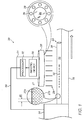
- FIG. 1 is a schematic illustration of a system 20 for inspecting a catheter shaft 22 during the manufacture thereof, in accordance with some embodiments of the present invention.
- Fig. 1 depicts the manufacture of catheter shaft 22 by manufacturing apparatus 24.
- the apparatus forms the catheter shaft from the raw materials.
- apparatus 24 may comprise one or more extrusion dies, and catheter shaft 22 may be formed by extrusion.
- catheter shaft 22 itself may be referred to as a "braided extrusion," or simply as an "extrusion."
- the techniques described herein may be applied to any other suitable type of manufacturing process, such as an additive manufacturing process.
- Catheter shaft 22 comprises an outer tube 38, which is typically made from a polymer. Outer tube 38 comprises an outer surface 23. Underneath outer tube 38, catheter shaft 22 comprises a supporting structure (or "skeletal structure") 27. Underneath structure 27, catheter shaft 22 comprises an inner tube, which is not shown in Fig. 1 .
- structure 27 comprises a braid.
- One type of braid shown in Fig. 1 , may be formed by winding a first coil 27a and a second coil 27b over the inner tube of the catheter shaft with the same pitch (alternatively referred to herein as a "spatial frequency") but with different orientations.
- one of the coils may be oriented (e.g., at a 45° angle) toward the distal end of the catheter shaft, while the other coil may be oriented (e.g., at a 45° angle) toward the proximal end of the catheter shaft.
- the pitch of the braid is the inverse of the distance d0 between successive crossing of the coils, d0 being measured along the longitudinal axis 52 of the catheter shaft.
- Other types of braids may be formed using any suitable combination of coils, loops, and/or straight wires, which may be oriented in any suitable way.
- structure 27 may comprise a single coil wound over the inner tube of the catheter shaft.
- the spatial frequency of the structure is the inverse of the distance between successive windings of the coil, this distance being measured along longitudinal axis 52.
- each coil in supporting structure 27 may comprise any suitable material, such as stainless steel, Nitinol, a polymer (e.g., a liquid-crystal polymer or polyether ether ketone), glass, and/or carbon fiber.
- the cross section of each coil may have any suitable shape, such as a circular or rectangular shape.
- System 20 comprises an inspection unit 21.
- the catheter shaft Upon exiting apparatus 24, the catheter shaft is carried, by a track 26, under inspection unit 21. (This movement is toward the right of the figure, as indicated by the right-pointing arrow at the bottom of the figure.)
- the speed at which track 26 moves - referred to as the "line speed" - may be, for example, between 8 and 70 cm/s.
- Unit 21 comprises a light source 28 and at least one imaging device 30, comprising, for example, an imaging lens and an imaging sensor, such as a charged coupled device (CCD) or complementary metal-oxide-semiconductor (CMOS).
- imaging device 30 acquires images of the reflection.
- the reflection does not appear as a uniform, straight line, due to the presence of structure 27 beneath the outer surface.
- structure 27 causes outer surface 23 to be uneven, in that the portions of outer surface 23 that lie directly over the structure are raised, relative to the other portions of the outer surface.
- the reflection includes alternating positive and negative peaks, and/or varies periodically in its intensity.
- System 20 further comprises a processor 32, which may be disposed within unit 21 or remotely therefrom.
- Processor 32 may be connected to imaging device 30 over any suitable wired or wireless interface, such that the images acquired by the imaging device are communicated to processor 32 over the interface.
- processor 32 processes the images, such as to ascertain the pitch of the supporting structure from the reflection of light 25 in the image.
- processor 32 may control the manufacturing of the catheter shaft such as to bring the pitch into accordance with the target pitch. (In other words, processor 32 may provide feedback for a closed control loop for controlling the pitch.) For example, the processor may adjust the temperature, pressure, and/or tension applied to the raw materials by apparatus 24, and/or the line speed, such as to correct the pitch.
- processor 32 may be connected to manufacturing apparatus 24 over any suitable wireless or wired communication interface 56.
- the processor may be connected to a controller belonging to manufacturing apparatus 24, such that the processor may instruct the controller to adjust any relevant manufacturing parameters.
- the catheter shaft is imaged at a rate that is sufficient for acquiring at least one image of every portion of the shaft.
- the minimum sufficient rate is a function of the line speed and of the size of the field of view of the imaging device.
- the images are acquired at a rate of at least 15, 30, or 60 frames per second, such that, typically, multiple images of each portion of the shaft are acquired.
- processor 32 is implemented solely in hardware, e.g., using one or more Application-Specific Integrated Circuits (ASICs) or Field-Programmable Gate Arrays (FPGAs).
- ASICs Application-Specific Integrated Circuits
- FPGAs Field-Programmable Gate Arrays
- the functionality of processor 32 is implemented at least partly in software.
- processor 32 may be embodied as a programmed digital computing device comprising at least a central processing unit (CPU) and random access memory (RAM).
- Program code, including software programs, and/or data are loaded into the RAM for execution and processing by the CPU.
- the program code and/or data may be downloaded to the processor in electronic form, over a network, for example.
- program code and/or data may be provided and/or stored on non-transitory tangible media, such as magnetic, optical, or electronic memory.
- program code and/or data when provided to the processor, produce a machine or special-purpose computer, configured to perform the tasks described herein.
- light source 28 comprises a set of light emitting diodes (LEDs) 36 arranged circularly around a central transparent window 34, behind which lies the imaging lens of imaging device 30.
- LEDs 36 may illuminate catheter shaft 22 simultaneously or in sequence, as further described below. As the LEDs illuminate the catheter shaft, the reflected light passes through window 34 to the imaging device.
- system 20 may comprise one or more light sources and one or more imaging devices, which may be disposed in any suitable configuration.
- Each light source may comprise any suitable number of light emitters (e.g., LEDs, lasers, fluorescent bulbs, incandescent bulbs, and/or halogen bulbs), which may be arranged in any suitable configuration (e.g., a circular or linear configuration).
- the one or more light beams emitted by each light source may have any suitable shape (e.g., a circular or linear shape).
- any suitable pattern of coherent or incoherent illumination may be obtained.
- the light emitted by each of the light sources may have any suitable frequency, or combination of frequencies, within the visible or invisible portion of the electromagnetic spectrum (provided that the imaging devices are configured to image these frequencies).
- system 20 comprises a mobile phone, which comprises the aforementioned light source, imaging device, and processor.
- system 20 may comprise additional optical elements, such as additional lenses or beam splitters, which facilitate the illumination and imaging functionality described herein.
- FIGs. 2A-C For various alternate configurations of system 20 in accordance with some embodiments of the present invention, reference is now made to Figs. 2A-C .
- FIGs. 2A-C shows a transverse cross-section through catheter shaft 22, along with various components of system 20.
- processor 32 is omitted from Figs. 2A-C .
- the transverse cross-section reveals outer tube 38 (comprising outer surface 23), an inner tube 40, a catheter shaft lumen 42 enclosed by inner tube 40, and supporting structure 27, disposed between outer tube 38 and inner tube 40.
- system 20 comprises multiple inspection units 21, each of which provides coaxial illumination and imaging as in Fig. 1 .
- each inspection unit illuminates the catheter shaft and receives the reflected light from the catheter shaft along a common axis.
- the inspection units are disposed at different respective angles with respect to the catheter shaft.
- the inspection units image the catheter shaft at the same frequency (i.e., at the same number of images per second), in phase with each other.
- the inspection units image the catheter shaft at different frequencies, or at the same frequency but with different phases.
- each imaging device typically images the catheter shaft at a rate that is sufficient for acquiring at least one image of every portion of the shaft, as described above with reference to Fig. 1 .
- a single processor 32 disposed within one of the imaging units or remotely therefrom, processes the images acquired by the imaging devices.
- processor 32 may use the multiple images to obtain a more accurate estimate of the spatial frequency of the underlying supporting structure; for example, the processor may average the spatial frequency across the images.
- the processor may select one or more images that show a more indicative reflection than the other images, and use only the selected images to ascertain the spatial frequency of the supporting structure.
- Fig. 2B light source 28 and imaging device 30 are disposed at different respective angles with respect to the catheter shaft, such that system 20 provides off-axis illumination and imaging.
- the illumination is delivered along a first axis, while the reflected light is received along a second, different axis.
- this off-axis configuration may provide a more indicative pattern of reflection, relative to a coaxial configuration.
- the embodiment of Fig. 2B may further include one or more other light sources that illuminate the catheter shaft from other positions.
- the reflection of the light beams from these light sources may be imaged by one or more other coaxial or off-axis imaging devices, and/or by the same imaging device.
- a single light source may be "shared" by multiple imaging devices, in that the reflection generated by the light source may be imaged by the devices from multiple different positions.
- respective images may be acquired by the multiple imaging devices at the same time, or at different times. In the event that the images are acquired at the same time, the processor may select some or all of the images for use in ascertaining the spatial frequency of the supporting structure.
- Fig. 2C as in Fig. 2B , light source 28 and imaging device 30 are disposed at different respective angles with respect to the catheter shaft. However, system 20 nonetheless provides coaxial illumination and imaging, by virtue of a beam splitter 44.
- the components shown in Fig. 2C may be combined with any number of other light sources, imaging devices, and/or other optical components, arranged in any suitable configuration.
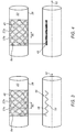
- FIG. 3 is a schematic illustration of a method for ascertaining the spatial frequency of supporting structure 27, in accordance with some embodiments of the present invention.
- the supporting structure comprises a braid, comprising two coils wound around inner tube 40 at the same pitch but with opposite orientations.
- the supporting structure causes unevenness in outer surface 23 of outer tube 38, such that the reflection 46 of light from the outer surface may exhibit certain non-uniformities.
- the shape of reflection 46 may vary periodically along axis 52.
- the reflection may be shaped to define a sinusoid (or any approximation to a sinusoid) having alternating positive peaks 48 and negative peaks 50, whereby positive peaks 48 are attained at the points of maximum outward bulging of outer surface 23, while negative peaks 50 correspond to the points of minimal outward bulging.
- the spatial frequency of the supporting structure may be ascertained based on the frequency of the sinusoid.
- the processor may compute the spatial frequency of the braid by (i) detecting the positive peaks of the sinusoid, (ii) computing the distance in pixels between a pair of successive positive peaks, or the average of this distance over multiple such pairs, (iii) scaling the inter-peak distance in accordance with the size of the field of view (FOV) of the imaging device, such as to obtain the real-world distance between the positive peaks, and (iv) computing the inverse of the real-world distance.
- FOV field of view
- an FFT of the sinusoid may be computed, and the dominant frequency of the FFT may then be identified.
- the spatial frequency of the braid may be computed by scaling the dominant frequency in accordance with the size (in pixels) of the FOV and the magnification factor of the imaging lens. (Prior to the imaging, a calibration procedure may be performed, so as to learn the respective scale factors for different magnification factors.)
- FIG. 4 is a schematic illustration of another method for ascertaining the spatial frequency of supporting structure 27, in accordance with some embodiments of the present invention.
- reflection 46 exhibits a spatially-periodic intensity, whereby the intensity is highest directly above the supporting structure.
- the spatial frequency of the supporting structure may be ascertained based on the spatial frequency of the reflection.
- the processor may derive, from the image, a periodic function B(x) that describes the brightness of the reflection in the image, x being the distance along longitudinal axis 52. Subsequently, the processor may calculate the spatial frequency of the supporting structure by applying the above-described peak detection technique or FFT technique to B(x).
- processor 32 applies a software-implemented color filter to each image, prior to processing the image as described above with reference to Figs. 3-4 .
- a filter may, for example, filter out the color of outer tube 38, so as to increase the contrast between reflection 46 and the surrounding pixels.
- a physical color filter may filter the light received by imaging device 30.
- One example of the FFT computation referred to above includes use of MATLAB@ to perform a two-dimensional FFT.
- the MATLAB@ function "fft2" may be called, and the pitch of the braid may then be derived from the frequency at which the FFT attains its maximum value.
- FIG. 5 is a flow diagram for a method 58 for identifying the pitch of a braid, in accordance with some embodiments of the present invention.
- the algorithm 58 begins with a thresholding step 60, at which processor 32 applies a suitable threshold to the image, setting any pixels whose value is less than the threshold to zero.
- the threshold that is used is the minimum brightness value that the reflection is expected to attain in the image. (This thresholding operation was referred to above as the application of a "brightness filter" to the image.).
- One skilled in the art would be able to utilize algorithm 58 to generate suitable computer codes to perform the processing of the image.
- the processor identifies the respective y-coordinates of the N greatest non-zero pixels in each column of the image, for those columns that contain at least N non-zero pixels. (The MATLAB@ function "find" may be used for this purpose.)
- the processor computes, for each column for which the aforementioned y-coordinates were identified, the average of the identified y-coordinates. The processor thus obtains a reflection-position function, which associates an average y-coordinate, representing the vertical position of the reflection, with each x-coordinate along the length of the reflection.
- the processor performs a one-dimensional FFT on the reflection-position function, at an FFT-performing step 64.
- the MATLAB@ function "fft" may be used for this purpose.
- the processor identifies the dominant frequency in the FFT.
- the processor derives the pitch of the braid from the dominant frequency, e.g., by scaling the dominant frequency in accordance with the size of the FOV and the magnification factor of the imaging lens.
- Fig. 5 assumes that the reflection has a horizontal orientation in the image, it is noted that method 58 may be similarly applied to a reflection having a vertical orientation, mutatis mutandis.
- Fig. 5 assumes that the pitch is derived from the periodically-varying position of the reflection in the image, it is noted that method 58 may be similarly used to derive the pitch of the braid from the periodically-varying brightness of the image, mutatis mutandis.
- multiple images which vary from each other in the position and/or shape of the reflection that is shown, are acquired at approximately the same time, e.g., such that the last image is acquired within 1-100 (e.g., within 5-50) milliseconds of the first image.
- the processor identifies at least one of these images as being more indicative of the spatial frequency of the supporting structure than the other images. The processor therefore selects the identified image - without selecting the other images - for processing.
- the processor may select, for processing, one of several reflections that are shown in an image, without selecting the other reflections.
- this technique may facilitate estimating the pitch of the supporting structure with greater accuracy.
- the pitch may be estimated with greatest accuracy when the reflection is aligned with crossings 54.
- multiple images which show reflections at different respective positions along the circumference of the catheter shaft, may be acquired.
- the processor may select the image in which the reflection appears to be most closely aligned with crossings 54.
- a single image which shows multiple reflections at different respective positions along the circumference of the catheter shaft, may be acquired, and the processor may then select the reflection that appears to be most closely aligned with crossings 54.
- light source 28 is configured to illuminate the catheter shaft at various different positions along the circumference of the shaft.
- the circular arrangement of LEDs 36 shown in Fig. 1 may generate two separate reflections, aligned with axis 52 at different respective positions along the shaft circumference, when all of the LEDs are lit.
- LEDs 36, or subsets of LEDs 36 may be alternatingly lit in rapid succession (e.g., such that the last LED is lit within 1-100, such as within 5-50, milliseconds of the first LED), such that various different reflections are rapidly generated.
- the illumination and/or imaging of the catheter shaft may be conducted from multiple different positions, as described above with reference to Figs. 2A-C .
- multiple different light sources and/or imaging devices disposed at different respective locations, may be used.
- a light source and/or imaging device may be moved with respect to the catheter shaft while the images are acquired.
- track 26, and/or a separate jittering mechanism may jitter the catheter shaft as the catheter shaft passes underneath the inspection system, such that the shape and/or position of the reflection is varied.
- the processor compares at least one parameter of the reflection, as exhibited in each of the images, to the parameter as exhibited in the other images. Subsequently, in response to the comparison, the processor may select at least one image, but not the other images, for processing.
- One such parameter is the average or median peak-to-peak amplitude of the reflection (i.e., the average or median difference between positive peaks 48 and negative peaks 50), or of the intensity of the reflection.
- the processor may select those images showing a greater peak-to-peak amplitude, relative to the other images.
- This amplitude may be normalized by the sum of the absolute values of the peaks; for example, given a positive peak A max and a negative peak A min , the normalized peak-to-peak amplitude may be defined as (A max -A min )/(A max +A min ).
- Another such parameter is the energy of the dominant frequency of the reflection or of the intensity of the reflection, relative to other frequencies.
- the processor may compute an FFT of each of the reflections, and/or of the brightness function B(x) for each of the reflections. For each FFT, the processor may compute the percentage difference between the highest peak of the FFT and the second-highest peak. The processor may then select those images having a greater percentage difference, relative to the other images.
- the processor may also use the techniques described above to select a reflection from multiple reflections that are shown in a single image.
Landscapes
- Health & Medical Sciences (AREA)
- Life Sciences & Earth Sciences (AREA)
- General Health & Medical Sciences (AREA)
- Physics & Mathematics (AREA)
- Engineering & Computer Science (AREA)
- Pathology (AREA)
- Heart & Thoracic Surgery (AREA)
- Animal Behavior & Ethology (AREA)
- Biophysics (AREA)
- Biomedical Technology (AREA)
- Veterinary Medicine (AREA)
- Public Health (AREA)
- Surgery (AREA)
- General Physics & Mathematics (AREA)
- Analytical Chemistry (AREA)
- Immunology (AREA)
- Chemical & Material Sciences (AREA)
- Biochemistry (AREA)
- Pulmonology (AREA)
- Anesthesiology (AREA)
- Hematology (AREA)
- Medical Informatics (AREA)
- Optics & Photonics (AREA)
- Radiology & Medical Imaging (AREA)
- Nuclear Medicine, Radiotherapy & Molecular Imaging (AREA)
- Molecular Biology (AREA)
- Manufacturing & Machinery (AREA)
- Textile Engineering (AREA)
- Media Introduction/Drainage Providing Device (AREA)
- Endoscopes (AREA)
- Length Measuring Devices By Optical Means (AREA)
- Length Measuring Devices With Unspecified Measuring Means (AREA)
- Length-Measuring Instruments Using Mechanical Means (AREA)
Abstract
Description
- The present invention relates generally to the manufacture of braided structures, such as braided extrusions for use in intrabody catheter shafts and other tubular devices.
- Some tubular devices, such as the shafts of intrabody catheters, comprise an inner tube and an outer tube, with a braided skeletal structure positioned between the two tubes. The braid imparts stability, along with other mechanical properties, to the catheter. The pitch of the braid is typically measured in units of picks per inch (PPI).
- There is provided, in accordance with some embodiments of the present invention, a system for inspecting a tubular device that includes an outer surface and a spatially-periodic supporting structure beneath the outer surface. The system includes an imaging device, configured to acquire an image of a reflection of light from the outer surface, and a processor, configured to ascertain a spatial frequency of the supporting structure by processing the image.
- In some embodiments, the system further includes a light source, configured to illuminate the outer surface with the light so as to generate the reflection.
- In some embodiments, the processor is further configured to, in response to the spatial frequency being different from a target spatial frequency, control a manufacturing of the tubular device so as to bring the spatial frequency into accordance with the target spatial frequency.
- In some embodiments, the supporting structure is selected from the group of supporting structures consisting of: a coil, and a braid.
- In some embodiments, the reflection is shaped to define a sinusoid, and the processor is configured to ascertain the spatial frequency of the supporting structure based on a frequency of the sinusoid.
- In some embodiments, the processor is further configured to, prior to processing the image:
- compare a parameter of the sinusoid, as exhibited in the image, to the parameter as exhibited in another image, and
- select the image, but not the other image, for the processing, in response to the comparison.
- In some embodiments, the parameter includes a peak-to-peak amplitude of the sinusoid.
- In some embodiments, the parameter includes an energy of a dominant frequency of the sinusoid.
- In some embodiments, the spatial frequency of the supporting structure is a first spatial frequency, and the processor is configured to ascertain the first spatial frequency based on a second spatial frequency of an intensity of the reflection.
- There is further provided, in accordance with some embodiments of the present invention, a method that includes, using a light source, illuminating an outer surface of a tubular device with light, the tubular device including a spatially-periodic supporting structure beneath the outer surface. The method further includes, while illuminating the outer surface, using an imaging device, acquiring an image of a reflection of the light from the outer surface. The method further includes, by processing the image, ascertaining a spatial frequency of the supporting structure.
- In some embodiments, illuminating the outer surface includes illuminating the outer surface while the tubular device is being manufactured.
- In some embodiments, the supporting structure includes at least two coils that are braided with one another, and illuminating the outer surface includes illuminating the outer surface such that peaks of the sinusoid are located at respective crossings of the coils.
- There is further provided, in accordance with some embodiments of the present invention, a computer software product including a tangible non-transitory computer-readable medium in which program instructions are stored. The instructions, when read by a processor, cause the processor to receive an image of a reflection of light from an outer surface of a tubular device that includes a spatially-periodic supporting structure beneath the outer surface, and to ascertain a spatial frequency of the supporting structure by processing the image.
- The present invention will be more fully understood from the following detailed description of embodiments thereof, taken together with the drawings, in which:
-
-
Fig. 1 is a schematic illustration of a system for inspecting a catheter shaft during the manufacture thereof, in accordance with some embodiments of the present invention; -
Figs. 2A-C schematically illustrate various alternate configurations of the system ofFig. 1 , in accordance with some embodiments of the present invention; -
Figs. 3-4 are schematic illustrations of methods for ascertaining the spatial frequency of a supporting structure, in accordance with some embodiments of the present invention; and -
Fig. 5 is a flow diagram for a method for identifying the pitch of a braid, in accordance with some embodiments of the present invention. - For a tubular device that comprises a supporting braid, as described above in the Background, the pitch of the braid may affect the mechanical properties of the device. It is therefore important to verify, during the manufacturing process, that the desired pitch of the braid is attained. One method for doing so is to cut away part of the outer tube of the device, and to then measure the pitch of the braid. However, this method involves interruptions to the manufacturing process, along with wasted materials. These disadvantages are especially pronounced in cases in which the pitch of the braid is required to change along the length of the device.
- To address this challenge, embodiments of the present invention use a non-destructive, non-invasive method of measuring the braid of the device, without interrupting the manufacturing process. This method takes advantage of the fact that the braid typically causes the outer tube of the device to bulge slightly outward, such that the outer surface of the device reflects light in a manner that depends on the pitch of the underlying braid. In particular, per the techniques disclosed herein, the surface of the device is illuminated while the device is in the process of being manufactured. Using a suitable imaging device, an image of the reflection of the light from the surface is captured. Subsequently, by processing the image, the pitch of the underlying braid is ascertained.
- In some cases, the position of the reflection in the image may vary periodically (e.g., sinusoidally), in that the reflection may include a series of alternating positive and negative peaks, the positive peaks corresponding to the points at which the braid passes beneath the surface. Alternatively or additionally, the intensity (or "brightness") of the reflection may vary periodically (e.g., sinusoidally), whereby the intensity attains its maximum value at the points at which the braid passes beneath the surface. (The type of periodicity that is exhibited generally depends on various factors, such as the type of light source that is used, the position of the light source relative to the device, and the position of the imaging device relative to the device.) Since each of these types of periodicity indicates the pitch of the underlying braid, the processing of the image may include the identification of one or both of these types of periodicity.
- For example, the processor may calculate the distance between the peaks in the reflection, and/or between the peaks in the intensity of the reflection, so that the pitch of the underlying braid may be ascertained. Alternatively, the processor may carry out a Fast Fourier Transform (FFT) of the position or intensity of the reflection, and the pitch may then be ascertained directly from the transform.
- Advantageously, the techniques described herein are non-destructive and cost-effective, and allow the braid to be inspected in real-time, as the device is manufactured, without interrupting the manufacturing process. Moreover, the techniques described herein greatly facilitate the inspection of more complex braid types, such as those with a variable (e.g., stepped) pitch. In the event that a deviation from the specifications is found, the manufacturing process may be adjusted in real-time, so as to salvage the device. Thus, the duration and cost of the manufacturing process may be reduced.
- Furthermore, the techniques described herein may be applied to most types of tubular devices, including those with properties that would inhibit the use of other inspection techniques. For example, the techniques described herein may be applied even to tubular devices whose outer tubes are opaque to visible light and/or x-rays, e.g., due to the thickness of the outer tube (e.g., by virtue of the outer tube comprising multiple layers of material), and/or due to impregnation of the outer tube with opaque materials such as colorants, lubricious agents, or radiopaque materials such as tungsten.
- Although the description below generally focuses on the manufacture of an intrabody catheter shaft, it is noted that the techniques described herein may be similarly applied to any other suitable tubular device that comprises a supporting braid. Examples of such devices include intrabody probe shafts, sheaths and other introducers for introducing intrabody devices into mammalian bodies, garden hoses, and other flexible conduits for the transport of liquids or gasses.
- Reference is initially made to
Fig. 1 , which is a schematic illustration of asystem 20 for inspecting acatheter shaft 22 during the manufacture thereof, in accordance with some embodiments of the present invention. -
Fig. 1 depicts the manufacture ofcatheter shaft 22 bymanufacturing apparatus 24. In the particular example shown, as raw materials pass throughapparatus 24, the apparatus forms the catheter shaft from the raw materials. For example,apparatus 24 may comprise one or more extrusion dies, andcatheter shaft 22 may be formed by extrusion. (In such a case, the catheter shaft itself may be referred to as a "braided extrusion," or simply as an "extrusion.") Alternatively, the techniques described herein may be applied to any other suitable type of manufacturing process, such as an additive manufacturing process. -
Catheter shaft 22 comprises anouter tube 38, which is typically made from a polymer.Outer tube 38 comprises anouter surface 23. Underneathouter tube 38,catheter shaft 22 comprises a supporting structure (or "skeletal structure") 27. Underneathstructure 27,catheter shaft 22 comprises an inner tube, which is not shown inFig. 1 . - In some cases,
structure 27 comprises a braid. One type of braid, shown inFig. 1 , may be formed by winding afirst coil 27a and asecond coil 27b over the inner tube of the catheter shaft with the same pitch (alternatively referred to herein as a "spatial frequency") but with different orientations. For example, one of the coils may be oriented (e.g., at a 45° angle) toward the distal end of the catheter shaft, while the other coil may be oriented (e.g., at a 45° angle) toward the proximal end of the catheter shaft. In this case, the pitch of the braid is the inverse of the distance d0 between successive crossing of the coils, d0 being measured along thelongitudinal axis 52 of the catheter shaft. Other types of braids may be formed using any suitable combination of coils, loops, and/or straight wires, which may be oriented in any suitable way. - Alternatively,
structure 27 may comprise a single coil wound over the inner tube of the catheter shaft. In this case, the spatial frequency of the structure is the inverse of the distance between successive windings of the coil, this distance being measured alonglongitudinal axis 52. - In general, each coil in supporting
structure 27 may comprise any suitable material, such as stainless steel, Nitinol, a polymer (e.g., a liquid-crystal polymer or polyether ether ketone), glass, and/or carbon fiber. The cross section of each coil may have any suitable shape, such as a circular or rectangular shape. -
System 20 comprises aninspection unit 21. Upon exitingapparatus 24, the catheter shaft is carried, by atrack 26, underinspection unit 21. (This movement is toward the right of the figure, as indicated by the right-pointing arrow at the bottom of the figure.) The speed at whichtrack 26 moves - referred to as the "line speed" - may be, for example, between 8 and 70 cm/s. -
Unit 21 comprises alight source 28 and at least oneimaging device 30, comprising, for example, an imaging lens and an imaging sensor, such as a charged coupled device (CCD) or complementary metal-oxide-semiconductor (CMOS). As the catheter shaft passes underneath the unit,light source 28 illuminatesouter surface 23 of the catheter shaft with light 25, such thatlight 25 is reflected by the outer surface through the imaging lens and onto the imaging sensor ofimaging device 30. While the catheter shaft is illuminated,imaging device 30 acquires images of the reflection. - As further described below with reference to
Figs. 3-4 , the reflection does not appear as a uniform, straight line, due to the presence ofstructure 27 beneath the outer surface. In particular,structure 27 causesouter surface 23 to be uneven, in that the portions ofouter surface 23 that lie directly over the structure are raised, relative to the other portions of the outer surface. Hence, the reflection includes alternating positive and negative peaks, and/or varies periodically in its intensity. -
System 20 further comprises aprocessor 32, which may be disposed withinunit 21 or remotely therefrom.Processor 32 may be connected toimaging device 30 over any suitable wired or wireless interface, such that the images acquired by the imaging device are communicated toprocessor 32 over the interface. As described in further detail below with reference toFigs. 3-4 ,processor 32 processes the images, such as to ascertain the pitch of the supporting structure from the reflection of light 25 in the image. - In response to ascertaining that the pitch is different from a target pitch that is specified in the relevant manufacturing specifications,
processor 32 may control the manufacturing of the catheter shaft such as to bring the pitch into accordance with the target pitch. (In other words,processor 32 may provide feedback for a closed control loop for controlling the pitch.) For example, the processor may adjust the temperature, pressure, and/or tension applied to the raw materials byapparatus 24, and/or the line speed, such as to correct the pitch. - To facilitate this control functionality,
processor 32 may be connected tomanufacturing apparatus 24 over any suitable wireless orwired communication interface 56. For example, the processor may be connected to a controller belonging tomanufacturing apparatus 24, such that the processor may instruct the controller to adjust any relevant manufacturing parameters. - Typically, the catheter shaft is imaged at a rate that is sufficient for acquiring at least one image of every portion of the shaft. (In general, the minimum sufficient rate is a function of the line speed and of the size of the field of view of the imaging device.) In some embodiments, the images are acquired at a rate of at least 15, 30, or 60 frames per second, such that, typically, multiple images of each portion of the shaft are acquired.
- In some embodiments, the functionality of
processor 32, as described herein, is implemented solely in hardware, e.g., using one or more Application-Specific Integrated Circuits (ASICs) or Field-Programmable Gate Arrays (FPGAs). In other embodiments, the functionality ofprocessor 32 is implemented at least partly in software. For example, in some embodiments,processor 32 may be embodied as a programmed digital computing device comprising at least a central processing unit (CPU) and random access memory (RAM). Program code, including software programs, and/or data are loaded into the RAM for execution and processing by the CPU. The program code and/or data may be downloaded to the processor in electronic form, over a network, for example. Alternatively or additionally, the program code and/or data may be provided and/or stored on non-transitory tangible media, such as magnetic, optical, or electronic memory. Such program code and/or data, when provided to the processor, produce a machine or special-purpose computer, configured to perform the tasks described herein. - In the particular embodiment shown,
light source 28 comprises a set of light emitting diodes (LEDs) 36 arranged circularly around a central transparent window 34, behind which lies the imaging lens ofimaging device 30.LEDs 36 may illuminatecatheter shaft 22 simultaneously or in sequence, as further described below. As the LEDs illuminate the catheter shaft, the reflected light passes through window 34 to the imaging device. - More generally,
system 20 may comprise one or more light sources and one or more imaging devices, which may be disposed in any suitable configuration. Each light source may comprise any suitable number of light emitters (e.g., LEDs, lasers, fluorescent bulbs, incandescent bulbs, and/or halogen bulbs), which may be arranged in any suitable configuration (e.g., a circular or linear configuration). The one or more light beams emitted by each light source may have any suitable shape (e.g., a circular or linear shape). Hence, any suitable pattern of coherent or incoherent illumination may be obtained. Furthermore, the light emitted by each of the light sources may have any suitable frequency, or combination of frequencies, within the visible or invisible portion of the electromagnetic spectrum (provided that the imaging devices are configured to image these frequencies). - In some embodiments,
system 20 comprises a mobile phone, which comprises the aforementioned light source, imaging device, and processor. Alternatively or additionally,system 20 may comprise additional optical elements, such as additional lenses or beam splitters, which facilitate the illumination and imaging functionality described herein. - For various alternate configurations of
system 20 in accordance with some embodiments of the present invention, reference is now made toFigs. 2A-C . Each ofFigs. 2A-C shows a transverse cross-section throughcatheter shaft 22, along with various components ofsystem 20. (For simplicity,processor 32 is omitted fromFigs. 2A-C .) The transverse cross-section reveals outer tube 38 (comprising outer surface 23), aninner tube 40, acatheter shaft lumen 42 enclosed byinner tube 40, and supportingstructure 27, disposed betweenouter tube 38 andinner tube 40. - In
Fig. 2A ,system 20 comprisesmultiple inspection units 21, each of which provides coaxial illumination and imaging as inFig. 1 . In other words, each inspection unit illuminates the catheter shaft and receives the reflected light from the catheter shaft along a common axis. The inspection units are disposed at different respective angles with respect to the catheter shaft. In some embodiments, the inspection units image the catheter shaft at the same frequency (i.e., at the same number of images per second), in phase with each other. In other embodiments, the inspection units image the catheter shaft at different frequencies, or at the same frequency but with different phases. In any case, each imaging device typically images the catheter shaft at a rate that is sufficient for acquiring at least one image of every portion of the shaft, as described above with reference toFig. 1 . - Typically, a
single processor 32, disposed within one of the imaging units or remotely therefrom, processes the images acquired by the imaging devices. In the event that multiple images of a single portion of the catheter shaft are acquired, at the same time, from different respective angles,processor 32 may use the multiple images to obtain a more accurate estimate of the spatial frequency of the underlying supporting structure; for example, the processor may average the spatial frequency across the images. Alternatively, as further described below with reference toFigs. 3-4 , the processor may select one or more images that show a more indicative reflection than the other images, and use only the selected images to ascertain the spatial frequency of the supporting structure. - In
Fig. 2B ,light source 28 andimaging device 30 are disposed at different respective angles with respect to the catheter shaft, such thatsystem 20 provides off-axis illumination and imaging. (In other words, the illumination is delivered along a first axis, while the reflected light is received along a second, different axis.) In some cases, this off-axis configuration may provide a more indicative pattern of reflection, relative to a coaxial configuration. - The embodiment of
Fig. 2B may further include one or more other light sources that illuminate the catheter shaft from other positions. The reflection of the light beams from these light sources may be imaged by one or more other coaxial or off-axis imaging devices, and/or by the same imaging device. Similarly, a single light source may be "shared" by multiple imaging devices, in that the reflection generated by the light source may be imaged by the devices from multiple different positions. As described above with reference toFig. 2A , respective images may be acquired by the multiple imaging devices at the same time, or at different times. In the event that the images are acquired at the same time, the processor may select some or all of the images for use in ascertaining the spatial frequency of the supporting structure. - In
Fig. 2C , as inFig. 2B ,light source 28 andimaging device 30 are disposed at different respective angles with respect to the catheter shaft. However,system 20 nonetheless provides coaxial illumination and imaging, by virtue of abeam splitter 44. The components shown inFig. 2C may be combined with any number of other light sources, imaging devices, and/or other optical components, arranged in any suitable configuration. - Reference is now made to
Fig. 3 , which is a schematic illustration of a method for ascertaining the spatial frequency of supportingstructure 27, in accordance with some embodiments of the present invention. - At the top of
Fig. 3 , a portion ofouter tube 38 is removed for illustration purposes, such as to show the spatially-periodic supporting structure underneath. In the particular example shown, as inFig. 1 , the supporting structure comprises a braid, comprising two coils wound aroundinner tube 40 at the same pitch but with opposite orientations. - As described above with reference to
Fig. 1 , the supporting structure causes unevenness inouter surface 23 ofouter tube 38, such that thereflection 46 of light from the outer surface may exhibit certain non-uniformities. For example, as shown in the bottom portion ofFig. 3 , the shape ofreflection 46 may vary periodically alongaxis 52. For example, the reflection may be shaped to define a sinusoid (or any approximation to a sinusoid) having alternatingpositive peaks 48 andnegative peaks 50, wherebypositive peaks 48 are attained at the points of maximum outward bulging ofouter surface 23, whilenegative peaks 50 correspond to the points of minimal outward bulging. In this case, the spatial frequency of the supporting structure may be ascertained based on the frequency of the sinusoid. - For example, after detecting the sinusoid (e.g., by applying a color filter and/or brightness filter to the image), the processor may compute the spatial frequency of the braid by (i) detecting the positive peaks of the sinusoid, (ii) computing the distance in pixels between a pair of successive positive peaks, or the average of this distance over multiple such pairs, (iii) scaling the inter-peak distance in accordance with the size of the field of view (FOV) of the imaging device, such as to obtain the real-world distance between the positive peaks, and (iv) computing the inverse of the real-world distance. Alternatively, an FFT of the sinusoid may be computed, and the dominant frequency of the FFT may then be identified. Subsequently, the spatial frequency of the braid may be computed by scaling the dominant frequency in accordance with the size (in pixels) of the FOV and the magnification factor of the imaging lens. (Prior to the imaging, a calibration procedure may be performed, so as to learn the respective scale factors for different magnification factors.)
- Reference is now made to
Fig. 4 , which is a schematic illustration of another method for ascertaining the spatial frequency of supportingstructure 27, in accordance with some embodiments of the present invention. - In some cases, alternatively or additionally to having a periodic shape,
reflection 46 exhibits a spatially-periodic intensity, whereby the intensity is highest directly above the supporting structure. Hence, the spatial frequency of the supporting structure may be ascertained based on the spatial frequency of the reflection. For example, the processor may derive, from the image, a periodic function B(x) that describes the brightness of the reflection in the image, x being the distance alonglongitudinal axis 52. Subsequently, the processor may calculate the spatial frequency of the supporting structure by applying the above-described peak detection technique or FFT technique to B(x). - In some embodiments,
processor 32 applies a software-implemented color filter to each image, prior to processing the image as described above with reference toFigs. 3-4 . Such a filter may, for example, filter out the color ofouter tube 38, so as to increase the contrast betweenreflection 46 and the surrounding pixels. Alternatively or additionally, a physical color filter may filter the light received by imagingdevice 30. - One example of the FFT computation referred to above includes use of MATLAB@ to perform a two-dimensional FFT. For example, to process each images of the catheter shaft, the MATLAB@ function "fft2" may be called, and the pitch of the braid may then be derived from the frequency at which the FFT attains its maximum value.
- Another computational approach, which utilizes a one-dimensional FFT, is illustrated in
Fig. 5 , which is a flow diagram for amethod 58 for identifying the pitch of a braid, in accordance with some embodiments of the present invention. - The
algorithm 58 begins with athresholding step 60, at whichprocessor 32 applies a suitable threshold to the image, setting any pixels whose value is less than the threshold to zero. In general, the threshold that is used is the minimum brightness value that the reflection is expected to attain in the image. (This thresholding operation was referred to above as the application of a "brightness filter" to the image.). One skilled in the art would be able to utilizealgorithm 58 to generate suitable computer codes to perform the processing of the image. - Next, at a coordinates-identifying step 61, for any suitable integer N (e.g., any integer between one and ten), the processor identifies the respective y-coordinates of the N greatest non-zero pixels in each column of the image, for those columns that contain at least N non-zero pixels. (The MATLAB@ function "find" may be used for this purpose.) Subsequently, at an average-
computing step 62, the processor computes, for each column for which the aforementioned y-coordinates were identified, the average of the identified y-coordinates. The processor thus obtains a reflection-position function, which associates an average y-coordinate, representing the vertical position of the reflection, with each x-coordinate along the length of the reflection. - Next, the processor performs a one-dimensional FFT on the reflection-position function, at an FFT-performing
step 64. (The MATLAB@ function "fft" may be used for this purpose.) Subsequently, at a dominant-frequency-identifying step 66, the processor identifies the dominant frequency in the FFT. Finally, at a pitch-deriving step 68, the processor derives the pitch of the braid from the dominant frequency, e.g., by scaling the dominant frequency in accordance with the size of the FOV and the magnification factor of the imaging lens. - Although
Fig. 5 assumes that the reflection has a horizontal orientation in the image, it is noted thatmethod 58 may be similarly applied to a reflection having a vertical orientation, mutatis mutandis. Similarly, althoughFig. 5 assumes that the pitch is derived from the periodically-varying position of the reflection in the image, it is noted thatmethod 58 may be similarly used to derive the pitch of the braid from the periodically-varying brightness of the image, mutatis mutandis. - In some embodiments, multiple images, which vary from each other in the position and/or shape of the reflection that is shown, are acquired at approximately the same time, e.g., such that the last image is acquired within 1-100 (e.g., within 5-50) milliseconds of the first image. Subsequently, the processor identifies at least one of these images as being more indicative of the spatial frequency of the supporting structure than the other images. The processor therefore selects the identified image - without selecting the other images - for processing. Alternatively or additionally, the processor may select, for processing, one of several reflections that are shown in an image, without selecting the other reflections.
- Advantageously, this technique may facilitate estimating the pitch of the supporting structure with greater accuracy. For example, in some cases, for a braid with crossed-over coils as shown in
Figs. 3-4 , the pitch may be estimated with greatest accuracy when the reflection is aligned withcrossings 54. Hence, multiple images, which show reflections at different respective positions along the circumference of the catheter shaft, may be acquired. Subsequently, the processor may select the image in which the reflection appears to be most closely aligned withcrossings 54. Alternatively, a single image, which shows multiple reflections at different respective positions along the circumference of the catheter shaft, may be acquired, and the processor may then select the reflection that appears to be most closely aligned withcrossings 54. - In some embodiments, to facilitate performing this technique,
light source 28 is configured to illuminate the catheter shaft at various different positions along the circumference of the shaft. For example, the circular arrangement ofLEDs 36 shown inFig. 1 may generate two separate reflections, aligned withaxis 52 at different respective positions along the shaft circumference, when all of the LEDs are lit. Alternatively,LEDs 36, or subsets ofLEDs 36, may be alternatingly lit in rapid succession (e.g., such that the last LED is lit within 1-100, such as within 5-50, milliseconds of the first LED), such that various different reflections are rapidly generated. - Alternatively or additionally, to vary the shapes and/or positions of the reflections that are imaged, the illumination and/or imaging of the catheter shaft may be conducted from multiple different positions, as described above with reference to
Figs. 2A-C . For example, multiple different light sources and/or imaging devices, disposed at different respective locations, may be used. Alternatively or additionally, a light source and/or imaging device may be moved with respect to the catheter shaft while the images are acquired. - Alternatively or additionally,
track 26, and/or a separate jittering mechanism, may jitter the catheter shaft as the catheter shaft passes underneath the inspection system, such that the shape and/or position of the reflection is varied. - Subsequently to receiving the multiple images, the processor compares at least one parameter of the reflection, as exhibited in each of the images, to the parameter as exhibited in the other images. Subsequently, in response to the comparison, the processor may select at least one image, but not the other images, for processing.
- One such parameter is the average or median peak-to-peak amplitude of the reflection (i.e., the average or median difference between
positive peaks 48 and negative peaks 50), or of the intensity of the reflection. In particular, the processor may select those images showing a greater peak-to-peak amplitude, relative to the other images. This amplitude may be normalized by the sum of the absolute values of the peaks; for example, given a positive peak Amax and a negative peak Amin, the normalized peak-to-peak amplitude may be defined as (Amax-Amin)/(Amax+Amin). - Another such parameter is the energy of the dominant frequency of the reflection or of the intensity of the reflection, relative to other frequencies. For example, the processor may compute an FFT of each of the reflections, and/or of the brightness function B(x) for each of the reflections. For each FFT, the processor may compute the percentage difference between the highest peak of the FFT and the second-highest peak. The processor may then select those images having a greater percentage difference, relative to the other images.
- As noted above, the processor may also use the techniques described above to select a reflection from multiple reflections that are shown in a single image.
- It will be appreciated by persons skilled in the art that the present invention is not limited to what has been particularly shown and described hereinabove. Rather, the scope of embodiments of the present invention includes both combinations and subcombinations of the various features described hereinabove, as well as variations and modifications thereof that are not in the prior art, which would occur to persons skilled in the art upon reading the foregoing description. Documents incorporated by reference in the present patent application are to be considered an integral part of the application except that to the extent any terms are defined in these incorporated documents in a manner that conflicts with the definitions made explicitly or implicitly in the present specification, only the definitions in the present specification should be considered.
Claims (16)
- A system for inspecting a tubular device that includes an outer surface and a spatially-periodic supporting structure beneath the outer surface, the system comprising:an imaging device, configured to acquire an image of a reflection of light from the outer surface; anda processor, configured to ascertain a spatial frequency of the supporting structure by processing the image.
- The system according to claim 1, further comprising a light source, configured to illuminate the outer surface with the light so as to generate the reflection.
- The system according to claim 1, wherein the processor is further configured to, in response to the spatial frequency being different from a target spatial frequency, control a manufacturing of the tubular device so as to bring the spatial frequency into accordance with the target spatial frequency.
- The system according to claim 1, wherein the reflection is shaped to define a sinusoid, and wherein the processor is configured to ascertain the spatial frequency of the supporting structure based on a frequency of the sinusoid.
- The system according to claim 4, wherein the processor is further configured to, prior to processing the image:compare a parameter of the sinusoid, as exhibited in the image, to the parameter as exhibited in another image, andselect the image, but not the other image, for the processing, in response to the comparison.
- The system according to claim 1, wherein the spatial frequency of the supporting structure is a first spatial frequency, and wherein the processor is configured to ascertain the first spatial frequency based on a second spatial frequency of an intensity of the reflection.
- A method, comprising:using a light source, illuminating an outer surface of a tubular device with light, the tubular device including a spatially-periodic supporting structure beneath the outer surface;while illuminating the outer surface, using an imaging device, acquiring an image of a reflection of the light from the outer surface; andby processing the image, ascertaining a spatial frequency of the supporting structure.
- The method according to claim 7, wherein illuminating the outer surface comprises illuminating the outer surface while the tubular device is being manufactured.
- The method according to claim 8, further comprising, in response to the spatial frequency being different from a target spatial frequency, controlling the manufacturing of the tubular device so as to bring the spatial frequency into accordance with the target spatial frequency.
- The system according to claim 1 or the method according to claim 7, wherein the supporting structure is selected from the group of supporting structures consisting of: a coil, and a braid.
- The method according to claim 7, wherein the reflection is shaped to define a sinusoid, and wherein ascertaining the spatial frequency of the supporting structure comprises ascertaining the spatial frequency of the supporting structure based on a frequency of the sinusoid.
- The method according to claim 11, further comprising, prior to processing the image:comparing a parameter of the sinusoid, as exhibited in the image, to the parameter as exhibited in another image, andselecting the image, but not the other image, for the processing, in response to the comparison.
- The system according to claim 5 or the method according to claim 12, wherein the parameter includes (i) a peak-to-peak amplitude of the sinusoid, or (ii) an energy of a dominant frequency of the sinusoid.
- The method according to claim 11, wherein the supporting structure includes at least two coils that are braided with one another, and wherein illuminating the outer surface comprises illuminating the outer surface such that peaks of the sinusoid are located at respective crossings of the coils.
- The method according to claim 7, wherein the spatial frequency of the supporting structure is a first spatial frequency, and wherein ascertaining the first spatial frequency comprises ascertaining the first spatial frequency based on a second spatial frequency of an intensity of the reflection.
- A computer software product comprising a tangible non-transitory computer-readable medium in which program instructions are stored, which instructions, when read by a processor, cause the processor to:receive an image of a reflection of light from an outer surface of a tubular device that includes a spatially-periodic supporting structure beneath the outer surface, andascertain a spatial frequency of the supporting structure by processing the image.
Applications Claiming Priority (1)
| Application Number | Priority Date | Filing Date | Title |
|---|---|---|---|
| US16/231,846 US11524136B2 (en) | 2018-12-24 | 2018-12-24 | Non-invasive measurement of the pitch of a braid |
Publications (2)
| Publication Number | Publication Date |
|---|---|
| EP3673785A1 true EP3673785A1 (en) | 2020-07-01 |
| EP3673785B1 EP3673785B1 (en) | 2021-08-25 |
Family
ID=69185098
Family Applications (1)
| Application Number | Title | Priority Date | Filing Date |
|---|---|---|---|
| EP19218132.9A Active EP3673785B1 (en) | 2018-12-24 | 2019-12-19 | Non-invasive measurement of the pitch of a braid |
Country Status (5)
| Country | Link |
|---|---|
| US (1) | US11524136B2 (en) |
| EP (1) | EP3673785B1 (en) |
| JP (2) | JP2020099698A (en) |
| CN (1) | CN111351791B (en) |
| IL (1) | IL271472B2 (en) |
Cited By (1)
| Publication number | Priority date | Publication date | Assignee | Title |
|---|---|---|---|---|
| EP4312019A1 (en) * | 2022-07-27 | 2024-01-31 | Biosense Webster (Israel) Ltd. | Inspection apparatus |
Families Citing this family (2)
| Publication number | Priority date | Publication date | Assignee | Title |
|---|---|---|---|---|
| US11524136B2 (en) * | 2018-12-24 | 2022-12-13 | Biosense Webster (Israel) Ltd. | Non-invasive measurement of the pitch of a braid |
| CN114563352B (en) * | 2022-04-27 | 2022-07-19 | 深圳市标谱半导体科技有限公司 | Light source installation component and braid detection device |
Citations (5)
| Publication number | Priority date | Publication date | Assignee | Title |
|---|---|---|---|---|
| JPS61112903A (en) * | 1984-11-07 | 1986-05-30 | Hokuyo Automatic Co | Outside-diameter measuring device |
| EP2471480A1 (en) * | 2010-12-29 | 2012-07-04 | Biosense Webster (Israel), Ltd. | Braid with integrated signal conductors |
| WO2014127856A1 (en) * | 2013-02-25 | 2014-08-28 | Subterandt Limited | Detection system and method of detecting corrosion under an outer protective layer |
| CN105387814B (en) * | 2015-12-04 | 2017-12-08 | 天津工业大学 | A kind of D braided composites preform surfaces parameter automatic measurement system |
| US20180055987A1 (en) * | 2016-08-30 | 2018-03-01 | B. Braun Avitum Ag | Detecting device for a medium inside a tube portion |
Family Cites Families (29)
| Publication number | Priority date | Publication date | Assignee | Title |
|---|---|---|---|---|
| US2513349A (en) * | 1946-10-23 | 1950-07-04 | Superior Tube Co | Tube making machine |
| US5075562A (en) * | 1990-09-20 | 1991-12-24 | Eastman Kodak Company | Method and apparatus for absolute Moire distance measurements using a grating printed on or attached to a surface |
| CH684129A5 (en) * | 1992-06-18 | 1994-07-15 | Zellweger Uster Ag | Method and device for assessing the effect of yarn defects on woven or knitted fabric. |
| JP3212373B2 (en) * | 1992-08-27 | 2001-09-25 | 信越化学工業株式会社 | Inspection method and inspection device for air bubbles and foreign matter in optical fiber preform |
| US5461481A (en) * | 1992-12-29 | 1995-10-24 | Research Technology International Company | System, apparatus and/or method for analyzing light intensities of light reflected from a surface of a sample |
| DE19613175C2 (en) * | 1996-04-02 | 1998-07-09 | Christian Dr Ing Beck | Process for complex measurement of thread parameters on external and internal threads and associated device |
| FR2752937B1 (en) * | 1996-08-30 | 1998-11-20 | Pacsys | INSTALLATION FOR THE ACQUISITION OF SINGULAR POINTS IN A PLANAR MATERIAL AND ITS APPLICATION TO THE ACQUISITION OF ISOLATED DEFECTS OR DEFECT AREAS IN A TEXTILE STRIP |
| JPH10267636A (en) * | 1997-03-28 | 1998-10-09 | New Kurieishiyon:Kk | Method and apparatus for surface inspection |
| US6606403B2 (en) * | 2000-05-04 | 2003-08-12 | Daniel Freifeld | Repetitive inspection system with intelligent tools |
| JP2002148029A (en) * | 2000-11-08 | 2002-05-22 | Ricoh Co Ltd | Apparatus and method for inspecting surface unevenness of cylindrical test object |
| US8303505B2 (en) | 2005-12-02 | 2012-11-06 | Abbott Cardiovascular Systems Inc. | Methods and apparatuses for image guided medical procedures |
| JP5505588B2 (en) * | 2008-06-20 | 2014-05-28 | 村田機械株式会社 | Filament winding equipment |
| JP5418763B2 (en) * | 2009-02-23 | 2014-02-19 | 横浜ゴム株式会社 | Method and apparatus for visual inspection of long objects |
| US9616195B2 (en) | 2009-04-03 | 2017-04-11 | Scientia Vascular, Llc | Micro-fabricated catheter devices having varying diameters |
| JP5549383B2 (en) * | 2009-08-07 | 2014-07-16 | 日本電気硝子株式会社 | Defect inspection method for glass tubes |
| JP5633719B2 (en) * | 2009-09-18 | 2014-12-03 | 学校法人福岡工業大学 | 3D information measuring apparatus and 3D information measuring method |
| EP2392895B1 (en) * | 2010-06-01 | 2013-03-06 | Tenaris Connections Ltd. | Method for measurement of geometrical parameters of coated threaded joints |
| DE102010047618A1 (en) * | 2010-10-07 | 2012-04-12 | Krones Aktiengesellschaft | Optical threaded position detection device |
| US8511214B2 (en) | 2011-04-21 | 2013-08-20 | Aga Medical Corporation | Tubular structure and method for making the same |
| US20130050830A1 (en) * | 2011-08-23 | 2013-02-28 | Boston Scientific Scimed, Inc. | Stent Inspection Mandrel |
| FI125119B (en) * | 2011-12-28 | 2015-06-15 | Metso Automation Oy | Measurement of a flat measuring object |
| JP6085134B2 (en) * | 2012-09-21 | 2017-02-22 | リコーエレメックス株式会社 | Inspection device |
| GB201222361D0 (en) * | 2012-12-12 | 2013-01-23 | Univ Birmingham | Surface geometry imaging |
| KR101415005B1 (en) * | 2013-10-16 | 2014-07-07 | 주식회사 서울금속 | 3-dimentional apparatus for inspecting object |
| GB201401564D0 (en) | 2014-01-30 | 2014-03-19 | Proton Products Ltd | A high speed magnetic oscillating device |
| MX353758B (en) * | 2014-12-19 | 2018-01-26 | Grober Leon S A De C V | Inspection system to identify defects in twisted strands. |
| ITUB20152984A1 (en) * | 2015-08-07 | 2017-02-07 | Nicro S P A | Radiant tube with corrugated shank. |
| US11524136B2 (en) * | 2018-12-24 | 2022-12-13 | Biosense Webster (Israel) Ltd. | Non-invasive measurement of the pitch of a braid |
| CN112229842A (en) * | 2020-09-07 | 2021-01-15 | 苏州汉特士视觉科技有限公司 | High-speed visual detection mechanism and device for braids |
-
2018
- 2018-12-24 US US16/231,846 patent/US11524136B2/en active Active
-
2019
- 2019-12-16 IL IL271472A patent/IL271472B2/en unknown
- 2019-12-19 EP EP19218132.9A patent/EP3673785B1/en active Active
- 2019-12-23 JP JP2019231175A patent/JP2020099698A/en active Pending
- 2019-12-24 CN CN201911347678.6A patent/CN111351791B/en active Active
-
2024
- 2024-07-17 JP JP2024113950A patent/JP7775383B2/en active Active
Patent Citations (5)
| Publication number | Priority date | Publication date | Assignee | Title |
|---|---|---|---|---|
| JPS61112903A (en) * | 1984-11-07 | 1986-05-30 | Hokuyo Automatic Co | Outside-diameter measuring device |
| EP2471480A1 (en) * | 2010-12-29 | 2012-07-04 | Biosense Webster (Israel), Ltd. | Braid with integrated signal conductors |
| WO2014127856A1 (en) * | 2013-02-25 | 2014-08-28 | Subterandt Limited | Detection system and method of detecting corrosion under an outer protective layer |
| CN105387814B (en) * | 2015-12-04 | 2017-12-08 | 天津工业大学 | A kind of D braided composites preform surfaces parameter automatic measurement system |
| US20180055987A1 (en) * | 2016-08-30 | 2018-03-01 | B. Braun Avitum Ag | Detecting device for a medium inside a tube portion |
Cited By (1)
| Publication number | Priority date | Publication date | Assignee | Title |
|---|---|---|---|---|
| EP4312019A1 (en) * | 2022-07-27 | 2024-01-31 | Biosense Webster (Israel) Ltd. | Inspection apparatus |
Also Published As
| Publication number | Publication date |
|---|---|
| IL271472B2 (en) | 2023-07-01 |
| US20200197661A1 (en) | 2020-06-25 |
| IL271472A (en) | 2020-06-30 |
| JP7775383B2 (en) | 2025-11-25 |
| JP2020099698A (en) | 2020-07-02 |
| IL271472B1 (en) | 2023-03-01 |
| US11524136B2 (en) | 2022-12-13 |
| CN111351791A (en) | 2020-06-30 |
| CN111351791B (en) | 2023-12-05 |
| JP2024138000A (en) | 2024-10-07 |
| EP3673785B1 (en) | 2021-08-25 |
Similar Documents
| Publication | Publication Date | Title |
|---|---|---|
| JP7775383B2 (en) | Non-invasive measurement of braid pitch | |
| CN114450711B (en) | Workpiece surface defect detection device and detection method, workpiece surface inspection system and program | |
| JP7028091B2 (en) | Surface defect detection device and surface defect detection method | |
| US11540884B2 (en) | Method and tracking system for tracking a medical object | |
| JPWO2006013635A1 (en) | Three-dimensional shape measuring method and apparatus | |
| JP2015173820A (en) | Image processing device, image processing method, and program | |
| JP6478713B2 (en) | Measuring device and measuring method | |
| US20080056446A1 (en) | Tire inspection method | |
| JPWO2015136853A1 (en) | Image processing apparatus, image processing method, and program | |
| JP2014062835A (en) | Inspection device | |
| JP2015083975A (en) | Method and scanner for touch free detection of positions and three-dimensional shapes of multiple products on running surface | |
| EP3070431B1 (en) | Visual inspection device and visual inspection method | |
| JP2015064301A (en) | Surface defect inspection apparatus and surface defect inspection method | |
| KR101327433B1 (en) | Apparatus for monitoring three-dimensional shape of target object | |
| CN111736235B (en) | Geometric parameter calibration parts and calibration methods for CT equipment | |
| JP2008309714A (en) | Visual inspection method of long article, and its device | |
| JP2015150369A (en) | Stent detector, stent image display device, stent detecting program, and stent detecting method | |
| CN110199173B (en) | Position offset acquisition device, inspection device, position offset acquisition method, and inspection method | |
| US20150268034A1 (en) | Method for evaluating fresnel diffraction border profiles | |
| US20150281544A1 (en) | Cardiovascular oct image making method and method for detecting stents using thereof | |
| JP6074284B2 (en) | Method and apparatus for measuring shape of belt-like rubber member | |
| KR100592956B1 (en) | Radiation imaging device and focusing method | |
| CN110987966A (en) | Detection method and detection system for curved substrate | |
| JP2008309708A (en) | Method and apparatus for visual inspection of long objects | |
| JP5413283B2 (en) | Focus shift detection device, focus shift detection method and program |
Legal Events
| Date | Code | Title | Description |
|---|---|---|---|
| PUAI | Public reference made under article 153(3) epc to a published international application that has entered the european phase |
Free format text: ORIGINAL CODE: 0009012 |
|
| STAA | Information on the status of an ep patent application or granted ep patent |
Free format text: STATUS: THE APPLICATION HAS BEEN PUBLISHED |
|
| AK | Designated contracting states |
Kind code of ref document: A1 Designated state(s): AL AT BE BG CH CY CZ DE DK EE ES FI FR GB GR HR HU IE IS IT LI LT LU LV MC MK MT NL NO PL PT RO RS SE SI SK SM TR |
|
| AX | Request for extension of the european patent |
Extension state: BA ME |
|
| STAA | Information on the status of an ep patent application or granted ep patent |
Free format text: STATUS: REQUEST FOR EXAMINATION WAS MADE |
|
| 17P | Request for examination filed |
Effective date: 20201102 |
|
| RBV | Designated contracting states (corrected) |
Designated state(s): AL AT BE BG CH CY CZ DE DK EE ES FI FR GB GR HR HU IE IS IT LI LT LU LV MC MK MT NL NO PL PT RO RS SE SI SK SM TR |
|
| GRAP | Despatch of communication of intention to grant a patent |
Free format text: ORIGINAL CODE: EPIDOSNIGR1 |
|
| STAA | Information on the status of an ep patent application or granted ep patent |
Free format text: STATUS: GRANT OF PATENT IS INTENDED |
|
| INTG | Intention to grant announced |
Effective date: 20210517 |
|
| GRAS | Grant fee paid |
Free format text: ORIGINAL CODE: EPIDOSNIGR3 |
|
| GRAA | (expected) grant |
Free format text: ORIGINAL CODE: 0009210 |
|
| STAA | Information on the status of an ep patent application or granted ep patent |
Free format text: STATUS: THE PATENT HAS BEEN GRANTED |
|
| AK | Designated contracting states |
Kind code of ref document: B1 Designated state(s): AL AT BE BG CH CY CZ DE DK EE ES FI FR GB GR HR HU IE IS IT LI LT LU LV MC MK MT NL NO PL PT RO RS SE SI SK SM TR |
|
| REG | Reference to a national code |
Ref country code: CH Ref legal event code: EP |
|
| REG | Reference to a national code |
Ref country code: IE Ref legal event code: FG4D Ref country code: AT Ref legal event code: REF Ref document number: 1422930 Country of ref document: AT Kind code of ref document: T Effective date: 20210915 |
|
| REG | Reference to a national code |
Ref country code: DE Ref legal event code: R096 Ref document number: 602019007182 Country of ref document: DE |
|
| REG | Reference to a national code |
Ref country code: NL Ref legal event code: FP |
|
| REG | Reference to a national code |
Ref country code: LT Ref legal event code: MG9D |
|
| REG | Reference to a national code |
Ref country code: AT Ref legal event code: MK05 Ref document number: 1422930 Country of ref document: AT Kind code of ref document: T Effective date: 20210825 |
|
| PG25 | Lapsed in a contracting state [announced via postgrant information from national office to epo] |
Ref country code: ES Free format text: LAPSE BECAUSE OF FAILURE TO SUBMIT A TRANSLATION OF THE DESCRIPTION OR TO PAY THE FEE WITHIN THE PRESCRIBED TIME-LIMIT Effective date: 20210825 Ref country code: SE Free format text: LAPSE BECAUSE OF FAILURE TO SUBMIT A TRANSLATION OF THE DESCRIPTION OR TO PAY THE FEE WITHIN THE PRESCRIBED TIME-LIMIT Effective date: 20210825 Ref country code: RS Free format text: LAPSE BECAUSE OF FAILURE TO SUBMIT A TRANSLATION OF THE DESCRIPTION OR TO PAY THE FEE WITHIN THE PRESCRIBED TIME-LIMIT Effective date: 20210825 Ref country code: NO Free format text: LAPSE BECAUSE OF FAILURE TO SUBMIT A TRANSLATION OF THE DESCRIPTION OR TO PAY THE FEE WITHIN THE PRESCRIBED TIME-LIMIT Effective date: 20211125 Ref country code: PT Free format text: LAPSE BECAUSE OF FAILURE TO SUBMIT A TRANSLATION OF THE DESCRIPTION OR TO PAY THE FEE WITHIN THE PRESCRIBED TIME-LIMIT Effective date: 20211227 Ref country code: FI Free format text: LAPSE BECAUSE OF FAILURE TO SUBMIT A TRANSLATION OF THE DESCRIPTION OR TO PAY THE FEE WITHIN THE PRESCRIBED TIME-LIMIT Effective date: 20210825 Ref country code: HR Free format text: LAPSE BECAUSE OF FAILURE TO SUBMIT A TRANSLATION OF THE DESCRIPTION OR TO PAY THE FEE WITHIN THE PRESCRIBED TIME-LIMIT Effective date: 20210825 Ref country code: AT Free format text: LAPSE BECAUSE OF FAILURE TO SUBMIT A TRANSLATION OF THE DESCRIPTION OR TO PAY THE FEE WITHIN THE PRESCRIBED TIME-LIMIT Effective date: 20210825 Ref country code: BG Free format text: LAPSE BECAUSE OF FAILURE TO SUBMIT A TRANSLATION OF THE DESCRIPTION OR TO PAY THE FEE WITHIN THE PRESCRIBED TIME-LIMIT Effective date: 20211125 Ref country code: LT Free format text: LAPSE BECAUSE OF FAILURE TO SUBMIT A TRANSLATION OF THE DESCRIPTION OR TO PAY THE FEE WITHIN THE PRESCRIBED TIME-LIMIT Effective date: 20210825 |
|
| PG25 | Lapsed in a contracting state [announced via postgrant information from national office to epo] |
Ref country code: PL Free format text: LAPSE BECAUSE OF FAILURE TO SUBMIT A TRANSLATION OF THE DESCRIPTION OR TO PAY THE FEE WITHIN THE PRESCRIBED TIME-LIMIT Effective date: 20210825 Ref country code: LV Free format text: LAPSE BECAUSE OF FAILURE TO SUBMIT A TRANSLATION OF THE DESCRIPTION OR TO PAY THE FEE WITHIN THE PRESCRIBED TIME-LIMIT Effective date: 20210825 Ref country code: GR Free format text: LAPSE BECAUSE OF FAILURE TO SUBMIT A TRANSLATION OF THE DESCRIPTION OR TO PAY THE FEE WITHIN THE PRESCRIBED TIME-LIMIT Effective date: 20211126 |
|
| PG25 | Lapsed in a contracting state [announced via postgrant information from national office to epo] |
Ref country code: DK Free format text: LAPSE BECAUSE OF FAILURE TO SUBMIT A TRANSLATION OF THE DESCRIPTION OR TO PAY THE FEE WITHIN THE PRESCRIBED TIME-LIMIT Effective date: 20210825 |
|
| REG | Reference to a national code |
Ref country code: DE Ref legal event code: R097 Ref document number: 602019007182 Country of ref document: DE |
|
| PG25 | Lapsed in a contracting state [announced via postgrant information from national office to epo] |
Ref country code: SM Free format text: LAPSE BECAUSE OF FAILURE TO SUBMIT A TRANSLATION OF THE DESCRIPTION OR TO PAY THE FEE WITHIN THE PRESCRIBED TIME-LIMIT Effective date: 20210825 Ref country code: SK Free format text: LAPSE BECAUSE OF FAILURE TO SUBMIT A TRANSLATION OF THE DESCRIPTION OR TO PAY THE FEE WITHIN THE PRESCRIBED TIME-LIMIT Effective date: 20210825 Ref country code: RO Free format text: LAPSE BECAUSE OF FAILURE TO SUBMIT A TRANSLATION OF THE DESCRIPTION OR TO PAY THE FEE WITHIN THE PRESCRIBED TIME-LIMIT Effective date: 20210825 Ref country code: EE Free format text: LAPSE BECAUSE OF FAILURE TO SUBMIT A TRANSLATION OF THE DESCRIPTION OR TO PAY THE FEE WITHIN THE PRESCRIBED TIME-LIMIT Effective date: 20210825 Ref country code: CZ Free format text: LAPSE BECAUSE OF FAILURE TO SUBMIT A TRANSLATION OF THE DESCRIPTION OR TO PAY THE FEE WITHIN THE PRESCRIBED TIME-LIMIT Effective date: 20210825 Ref country code: AL Free format text: LAPSE BECAUSE OF FAILURE TO SUBMIT A TRANSLATION OF THE DESCRIPTION OR TO PAY THE FEE WITHIN THE PRESCRIBED TIME-LIMIT Effective date: 20210825 |
|
| PLBE | No opposition filed within time limit |
Free format text: ORIGINAL CODE: 0009261 |
|
| STAA | Information on the status of an ep patent application or granted ep patent |
Free format text: STATUS: NO OPPOSITION FILED WITHIN TIME LIMIT |
|
| PG25 | Lapsed in a contracting state [announced via postgrant information from national office to epo] |
Ref country code: MC Free format text: LAPSE BECAUSE OF FAILURE TO SUBMIT A TRANSLATION OF THE DESCRIPTION OR TO PAY THE FEE WITHIN THE PRESCRIBED TIME-LIMIT Effective date: 20210825 |
|
| 26N | No opposition filed |
Effective date: 20220527 |
|
| PG25 | Lapsed in a contracting state [announced via postgrant information from national office to epo] |
Ref country code: SI Free format text: LAPSE BECAUSE OF FAILURE TO SUBMIT A TRANSLATION OF THE DESCRIPTION OR TO PAY THE FEE WITHIN THE PRESCRIBED TIME-LIMIT Effective date: 20210825 |
|
| REG | Reference to a national code |
Ref country code: BE Ref legal event code: MM Effective date: 20211231 |
|
| PG25 | Lapsed in a contracting state [announced via postgrant information from national office to epo] |
Ref country code: LU Free format text: LAPSE BECAUSE OF NON-PAYMENT OF DUE FEES Effective date: 20211219 Ref country code: IE Free format text: LAPSE BECAUSE OF NON-PAYMENT OF DUE FEES Effective date: 20211219 |
|
| PG25 | Lapsed in a contracting state [announced via postgrant information from national office to epo] |
Ref country code: BE Free format text: LAPSE BECAUSE OF NON-PAYMENT OF DUE FEES Effective date: 20211231 |
|
| PGFP | Annual fee paid to national office [announced via postgrant information from national office to epo] |
Ref country code: NL Payment date: 20221114 Year of fee payment: 4 Ref country code: FR Payment date: 20221110 Year of fee payment: 4 Ref country code: DE Payment date: 20221102 Year of fee payment: 4 |
|
| PGFP | Annual fee paid to national office [announced via postgrant information from national office to epo] |
Ref country code: IT Payment date: 20221231 Year of fee payment: 4 |
|
| PG25 | Lapsed in a contracting state [announced via postgrant information from national office to epo] |
Ref country code: CY Free format text: LAPSE BECAUSE OF FAILURE TO SUBMIT A TRANSLATION OF THE DESCRIPTION OR TO PAY THE FEE WITHIN THE PRESCRIBED TIME-LIMIT Effective date: 20210825 |
|
| PG25 | Lapsed in a contracting state [announced via postgrant information from national office to epo] |
Ref country code: HU Free format text: LAPSE BECAUSE OF FAILURE TO SUBMIT A TRANSLATION OF THE DESCRIPTION OR TO PAY THE FEE WITHIN THE PRESCRIBED TIME-LIMIT; INVALID AB INITIO Effective date: 20191219 |
|
| REG | Reference to a national code |
Ref country code: CH Ref legal event code: PL |
|
| PG25 | Lapsed in a contracting state [announced via postgrant information from national office to epo] |
Ref country code: LI Free format text: LAPSE BECAUSE OF NON-PAYMENT OF DUE FEES Effective date: 20221231 Ref country code: CH Free format text: LAPSE BECAUSE OF NON-PAYMENT OF DUE FEES Effective date: 20221231 |
|
| PG25 | Lapsed in a contracting state [announced via postgrant information from national office to epo] |
Ref country code: MK Free format text: LAPSE BECAUSE OF FAILURE TO SUBMIT A TRANSLATION OF THE DESCRIPTION OR TO PAY THE FEE WITHIN THE PRESCRIBED TIME-LIMIT Effective date: 20210825 |
|
| REG | Reference to a national code |
Ref country code: DE Ref legal event code: R119 Ref document number: 602019007182 Country of ref document: DE |
|
| REG | Reference to a national code |
Ref country code: NL Ref legal event code: MM Effective date: 20240101 |
|
| GBPC | Gb: european patent ceased through non-payment of renewal fee |
Effective date: 20231219 |
|
| PG25 | Lapsed in a contracting state [announced via postgrant information from national office to epo] |
Ref country code: NL Free format text: LAPSE BECAUSE OF NON-PAYMENT OF DUE FEES Effective date: 20240101 |
|
| PG25 | Lapsed in a contracting state [announced via postgrant information from national office to epo] |
Ref country code: NL Free format text: LAPSE BECAUSE OF NON-PAYMENT OF DUE FEES Effective date: 20240101 Ref country code: MT Free format text: LAPSE BECAUSE OF FAILURE TO SUBMIT A TRANSLATION OF THE DESCRIPTION OR TO PAY THE FEE WITHIN THE PRESCRIBED TIME-LIMIT Effective date: 20210825 |
|
| PG25 | Lapsed in a contracting state [announced via postgrant information from national office to epo] |
Ref country code: DE Free format text: LAPSE BECAUSE OF NON-PAYMENT OF DUE FEES Effective date: 20240702 |
|
| PG25 | Lapsed in a contracting state [announced via postgrant information from national office to epo] |
Ref country code: GB Free format text: LAPSE BECAUSE OF NON-PAYMENT OF DUE FEES Effective date: 20231219 |
|
| PG25 | Lapsed in a contracting state [announced via postgrant information from national office to epo] |
Ref country code: FR Free format text: LAPSE BECAUSE OF NON-PAYMENT OF DUE FEES Effective date: 20231231 |
|
| PG25 | Lapsed in a contracting state [announced via postgrant information from national office to epo] |
Ref country code: GB Free format text: LAPSE BECAUSE OF NON-PAYMENT OF DUE FEES Effective date: 20231219 Ref country code: FR Free format text: LAPSE BECAUSE OF NON-PAYMENT OF DUE FEES Effective date: 20231231 Ref country code: DE Free format text: LAPSE BECAUSE OF NON-PAYMENT OF DUE FEES Effective date: 20240702 |
|
| PG25 | Lapsed in a contracting state [announced via postgrant information from national office to epo] |
Ref country code: NL Free format text: LAPSE BECAUSE OF NON-PAYMENT OF DUE FEES Effective date: 20231231 |
|
| PG25 | Lapsed in a contracting state [announced via postgrant information from national office to epo] |
Ref country code: TR Free format text: LAPSE BECAUSE OF FAILURE TO SUBMIT A TRANSLATION OF THE DESCRIPTION OR TO PAY THE FEE WITHIN THE PRESCRIBED TIME-LIMIT Effective date: 20210825 |