EP3673593B1 - Vorrichtung und verfahren zur abbildung, vorrichtung und verfahren zur probabilistischen signalpunktformung - Google Patents
Vorrichtung und verfahren zur abbildung, vorrichtung und verfahren zur probabilistischen signalpunktformung Download PDFInfo
- Publication number
- EP3673593B1 EP3673593B1 EP18752788.2A EP18752788A EP3673593B1 EP 3673593 B1 EP3673593 B1 EP 3673593B1 EP 18752788 A EP18752788 A EP 18752788A EP 3673593 B1 EP3673593 B1 EP 3673593B1
- Authority
- EP
- European Patent Office
- Prior art keywords
- mapping
- mapping symbols
- symbols
- bits
- input
- Prior art date
- Legal status (The legal status is an assumption and is not a legal conclusion. Google has not performed a legal analysis and makes no representation as to the accuracy of the status listed.)
- Active
Links
- 238000013507 mapping Methods 0.000 title claims description 154
- 238000007493 shaping process Methods 0.000 title claims description 23
- 238000000034 method Methods 0.000 title claims description 21
- 238000009826 distribution Methods 0.000 claims description 44
- 230000001131 transforming effect Effects 0.000 claims description 10
- 238000004458 analytical method Methods 0.000 claims description 5
- 238000004590 computer program Methods 0.000 claims description 4
- 238000010586 diagram Methods 0.000 description 15
- 239000011159 matrix material Substances 0.000 description 11
- 238000004891 communication Methods 0.000 description 6
- 238000012545 processing Methods 0.000 description 4
- 230000009286 beneficial effect Effects 0.000 description 3
- 230000005540 biological transmission Effects 0.000 description 3
- 238000005457 optimization Methods 0.000 description 3
- YBJHBAHKTGYVGT-ZKWXMUAHSA-N (+)-Biotin Chemical compound N1C(=O)N[C@@H]2[C@H](CCCCC(=O)O)SC[C@@H]21 YBJHBAHKTGYVGT-ZKWXMUAHSA-N 0.000 description 2
- 230000001419 dependent effect Effects 0.000 description 2
- 238000002372 labelling Methods 0.000 description 2
- FEPMHVLSLDOMQC-UHFFFAOYSA-N virginiamycin-S1 Natural products CC1OC(=O)C(C=2C=CC=CC=2)NC(=O)C2CC(=O)CCN2C(=O)C(CC=2C=CC=CC=2)N(C)C(=O)C2CCCN2C(=O)C(CC)NC(=O)C1NC(=O)C1=NC=CC=C1O FEPMHVLSLDOMQC-UHFFFAOYSA-N 0.000 description 2
- 239000000654 additive Substances 0.000 description 1
- 230000000996 additive effect Effects 0.000 description 1
- 238000013459 approach Methods 0.000 description 1
- 238000003491 array Methods 0.000 description 1
- 238000004422 calculation algorithm Methods 0.000 description 1
- 238000004364 calculation method Methods 0.000 description 1
- 238000012937 correction Methods 0.000 description 1
- 238000013461 design Methods 0.000 description 1
- 238000012938 design process Methods 0.000 description 1
- 238000005315 distribution function Methods 0.000 description 1
- 230000003287 optical effect Effects 0.000 description 1
- 239000004065 semiconductor Substances 0.000 description 1
- 238000000926 separation method Methods 0.000 description 1
- 230000009897 systematic effect Effects 0.000 description 1
Images


Classifications
-
- H—ELECTRICITY
- H04—ELECTRIC COMMUNICATION TECHNIQUE
- H04L—TRANSMISSION OF DIGITAL INFORMATION, e.g. TELEGRAPHIC COMMUNICATION
- H04L1/00—Arrangements for detecting or preventing errors in the information received
- H04L1/004—Arrangements for detecting or preventing errors in the information received by using forward error control
- H04L1/0041—Arrangements at the transmitter end
- H04L1/0042—Encoding specially adapted to other signal generation operation, e.g. in order to reduce transmit distortions, jitter, or to improve signal shape
-
- H—ELECTRICITY
- H04—ELECTRIC COMMUNICATION TECHNIQUE
- H04L—TRANSMISSION OF DIGITAL INFORMATION, e.g. TELEGRAPHIC COMMUNICATION
- H04L1/00—Arrangements for detecting or preventing errors in the information received
- H04L1/004—Arrangements for detecting or preventing errors in the information received by using forward error control
- H04L1/0056—Systems characterized by the type of code used
- H04L1/0071—Use of interleaving
-
- H—ELECTRICITY
- H04—ELECTRIC COMMUNICATION TECHNIQUE
- H04L—TRANSMISSION OF DIGITAL INFORMATION, e.g. TELEGRAPHIC COMMUNICATION
- H04L1/00—Arrangements for detecting or preventing errors in the information received
- H04L1/004—Arrangements for detecting or preventing errors in the information received by using forward error control
- H04L1/0045—Arrangements at the receiver end
- H04L1/0047—Decoding adapted to other signal detection operation
- H04L1/005—Iterative decoding, including iteration between signal detection and decoding operation
-
- H—ELECTRICITY
- H04—ELECTRIC COMMUNICATION TECHNIQUE
- H04L—TRANSMISSION OF DIGITAL INFORMATION, e.g. TELEGRAPHIC COMMUNICATION
- H04L1/00—Arrangements for detecting or preventing errors in the information received
- H04L1/004—Arrangements for detecting or preventing errors in the information received by using forward error control
- H04L1/0056—Systems characterized by the type of code used
- H04L1/0057—Block codes
- H04L1/0058—Block-coded modulation
-
- H—ELECTRICITY
- H04—ELECTRIC COMMUNICATION TECHNIQUE
- H04L—TRANSMISSION OF DIGITAL INFORMATION, e.g. TELEGRAPHIC COMMUNICATION
- H04L27/00—Modulated-carrier systems
- H04L27/32—Carrier systems characterised by combinations of two or more of the types covered by groups H04L27/02, H04L27/10, H04L27/18 or H04L27/26
- H04L27/34—Amplitude- and phase-modulated carrier systems, e.g. quadrature-amplitude modulated carrier systems
- H04L27/3405—Modifications of the signal space to increase the efficiency of transmission, e.g. reduction of the bit error rate, bandwidth, or average power
Definitions
- the present disclosure relates to a mapping device and method.
- the present disclosure relates further to a probabilistic signal point shaping device and method using such a mapping device and method.
- the BICM capacity is a function of the channel noise model (e.g. AWGN; Additive White Gaussian Noise) and its properties (e.g. probability density function, variance), the signal points (e.g. QAM) and their position within the complex plane (e.g. rectangular 16-QAM), and the probability of occurrence of signal points.
- AWGN Additive White Gaussian Noise
- properties e.g. probability density function, variance
- the signal points e.g. QAM
- their position within the complex plane e.g. rectangular 16-QAM
- Optimization of BICM capacity is desired to maximize link throughput over a given transmit bandwidth and signal to noise ratio. It can be either achieved by signal point optimization (e.g. non-uniform constellation NUC), by probability optimization, or both.
- signal point optimization e.g. non-uniform constellation NUC
- probability optimization e.g. probability optimization
- mapping device and method as well as a corresponding probabilistic signal point shaping device and method that optimize BICM capacity for a multi-user scenario. It is a further object to provide a corresponding computer program for implementing said methods.
- the invention provides a mapping device according to independent claim 1, a computer-implemented mapping method according to independent claim 9 and a computer program according to independent claim 15.
- One of the aspects of the disclosure is to provide a mapping device and method that can be used for a multi-user scenario in which messages shall be transmitted to multiple users.
- a multi-user (MU) operation is disclosed by means of superposition coding.
- PAS probabilistic amplitude shaping
- signal point constellation a complex plane
- signal point constellation a complex plane
- PAS probabilistic signal point shaping
- One of the ideas of these enhancements to PAS is to generate a signal point constellation in which the probability of occurrence is non-uniform. It has been shown that this approach comes close to the upper bound of channel capacity measures.
- simultaneous IQ distribution matching is disclosed, which allows use of signal point constellations combining odd numbers of bits and allows bandwidth efficient communications for channels other than AWGN.
- Fig. 1 shows a schematic diagram of a first embodiment of a probabilistic signal point shaping device 10 according to the present disclosure.
- This device applies a transmission scheme which optimizes the probability of occurrence of signal points.
- the bit stream to be transmitted is D K with length K.
- a constant composition distribution matcher (CCDM) 11 generates n mapping symbols A 1 , ... , A n each being assigned to (or represented by) a particular signal point.
- a CCDM as such is e.g. known from Schulte, P. and Böcherer, G.; "Constant Composition Distribution Matching", IEEE Trans. Inf. Theory, vol. 62, no. 1, pp. 430-434, Jan. 2016 .
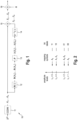
- mapping symbols are non-uniformly spaced, i.e. the distances between each pair of two neighboring signal points are not equal, if the mapping symbols are real-valued and are represented by amplitude levels. These amplitude levels are non-uniformly spaced as shown in Fig. 2 .
- the mapping symbols A 1 , ... , A n are non-uniformly distributed onto these four different amplitude level L 1 , ... , L 4 according to a predetermined probability distribution as also indicated in Fig. 2 .
- the amplitude levels L 1 , ... , L 4 determine a kind of "alphabet" of the CCDM source, whereas the mapping symbols A 1 , ... , A n are different realizations from that CCDM source.
- each amplitude level features a certain predetermined probability of occurrence.
- the CCDM 11 (or general circuitry, such as a processor or other hardware) thus maps data blocks of input bits of the input bit stream D K onto mapping symbols A 1 , ... , A n , wherein said mapping symbols are taken from non-uniformly spaced signal points, in the example shown in Fig. 2 represented by amplitude levels, according to a predetermined probability distribution.
- the probability of occurrence of these amplitude levels approximate a predefined probability distribution (which shall be optimized).
- the mapping of the data blocks of the input bit stream D K to signal points is invertible, i.e. the receiver recovers bits from signal points (e.g. amplitude levels) loss less.
- Each signal point gets assigned a bit combination (also called bit label) by the bit label assigner 12 (block b(.) in Fig. 1 ) or a corresponding circuitry.
- the number N of different amplitude level L 1 , ... , L N corresponds to an integer power of 2. For instance, as shown in Fig.
- bit labels 00 (to L 1 ), 01 (to L 2 ), 10 (to L 3 ), and 11 (to L 4 ) are assigned.
- a corresponding bit label is assigned to the respective mapping symbol.
- the bit label 10 is assigned to amplitude level L 3
- the bit label 10 is finally assigned to the mapping symbols A 1 and A 3 .
- the assigned bit labels are generally referred to as b ( A 1 ) , ... , b ( A n ) .
- the bits generated by the bit label assigner 12 are passed to a redundancy generator 13 using a parity matrix P which originates from a systematic forward error correction (FEC) code of a given rate.
- the redundancy generator 13 uses the P matrix to generate, based on it input bits b ( A 1 ), ... , b ( A n ) (i.e. the bits of the bit labels), redundancy bits, in this embodiment parity bits b ( S 1 ), ... , b ( S n ), at its output.
- the P matrix preferably originates from a FEC code with code rate m ⁇ 1 m with m -1 being the number of bits assigned to each mapping symbol.
- the parity bits b ( S 1 ) , ... , b ( S n ) are transformed into a redundancy rule by a transforming unit 14 (block b -1 (.) in Fig. 1 ) or a corresponding circuitry.
- the redundancy rule in this embodiment is a multiplication factor S 1 , ... , S n of +1 or -1, i.e. a sign function, but other ways to implement the redundancy rule are well possible, such as a mirroring operation.
- the multiplication factor S 1 , ... , S n is multiplied in a multiplier 15 or a corresponding circuitry with the mapping symbols A 1 , ... , A n output from the constant-composition distribution matcher 11 (CCDM) to generate output symbols X 1 , ... , X n .
- the parity bits influence the sign of the mapping symbols A 1 , ... , A n .
- multiplication with a scaling factor ⁇ in scaling unit 16 or a corresponding circuitry rescales output symbols X 1 , ... , X n such that desired (e.g. unity) transmit power is achieved.
- desired e.g. unity
- the communication rated can be increased considerably.
- the CCDM algorithm which is described in the above cited paper of Schulte and Böcherer has three inputs, i.e. bits to be transmitted, desired output symbols and desired probability of occurrence of the output symbols. It generates based on input parameters an output symbol sequence which fulfills the desired probability of occurrence. If output symbols are complex-valued or non-uniform, it will output complex-valued or non-uniform symbols. The operation itself is unchanged compared to the operation described in this paper.
- the CCDM as described in this paper may thus be applied as described in this paper, i.e. it outputs real valued and uniform amplitude levels, and a mapping unit may then be attached.
- This mapping unit performs an invertible one-to-one mapping between real-valued, uniform amplitude levels and complex-valued signal points or non-uniform amplitude levels.
- the CCDM alphabet (the amplitude levels) may be 1, 3, 5, 7 and a mapping unit allocates 1 to 1, 3 to 1+j, 5 to 5 and 7 to 2+j. This implements a CCDM with complex-valued output symbols.
- the CCDM thus basically works by dividing the [0, 1] intervals into equal length sub-intervals each assigned to one of the constant composition output sequence. Afterwards, equally spaced points positioned on the [0, 1] intervals are each assigned to the input binary sequences. During the distribution matching process, the CCDM will admit an input binary sequence, find its assigned points, find on which sub-intervals the point lies and finally output a constant composition sequence which is assigned to such sub-interval.
- Fig. 3 shows a schematic diagram of a second embodiment of a probabilistic signal point shaping device 20 according to the present disclosure.
- This embodiment enables the use of the P matrix from the FEC with different code rates, i.e. code rate different from m ⁇ 1 m .
- the length of the bypassed data bit k by of another (bypass) input bit stream D Kby can be matched to the rate of FEC code.
- the additional input bits are appended to the parity generated by the redundancy generator 13. Then, these extended bit sequences are mapped to signs by the transforming unit 14. Care is taken during the design phase to ensure that the length of this extended sequence is equal to the CCDM output.
- the number of amplitudes preferably matches the number of signs, which imposes restrictions to the code.
- the idea of additional input bits is to overcome these restrictions. Thus, if the parity matrix is from a code with higher code rate than m ⁇ 1 m , additional bits are used (where 2 m -1 is the number of amplitudes or equivalently m-1 is the number of bits assigned to each mapping symbol).
- mapping symbols are output from a source featuring two different amplitude levels (e.g. 1 and 3).
- the bit label assigner 12 allocates one bit for each amplitude level (e.g. for amplitude level 1 bit label 0 is assigned and for amplitude level 3 bit label 1 is assigned).
- the redundancy generator 13 generates for each input bit one output bit and the transforming unit 14 does bit to sign mapping (e.g. bit 0 is transformed into sign -1 and bit 1 is transformed into sign +1).
- the number of mapping symbols (1000) matches the number of signs (1000).
- a P matrix from a code with rate 2/3 (i.e. bypass needed for two amplitude levels, i.e. the embodiment shown in Fig. 3 may be applied) shall be considered.
- the operation is as described above but has a difference at the redundancy generator 13 which generates one output bit for two input bits.
- bypass bits are used. Assuming x bits are from the input bit stream D K and y bits are from the bypass bit stream D Kby , both are concatenated before the redundancy generation, i.e. x + y bits are input into the redundancy generator 13. After the redundancy generator 13 x/2+y/2 +y bits are given (+y comes from concatenation with bypass bits).
- the actual value of x and y depends on the block length of the P matrix such that the number of data bit in the parity matrix is equal to x + y . This constraint induces a system of linear equations that can be used to find a specific integer x and y which is matched to the property of the parity matrix P.
- non-uniformly spaced amplitude levels are applied for the CCDM output, i.e. at least one distance between two neighboring signal points is different from all other distances between neighboring signal points. If the PAS scheme explained above is applied component-wise, e.g. I and Q component independently, the constellation seen on the channel is of non-uniform type.
- each 1D constellation projection would comprise a number of signal points which is different from a power of two). For those cases, more flexibility with respect to signal point position and probability of occurrence of signal points is beneficial.
- the CCDM output defines complex-valued signal points, each associated with a probability of occurrence, i.e. the CCDM maps the data blocks of input bits of the input bit stream onto complex-valued mapping symbols, wherein said complex-valued mapping symbols are uniformly or non-uniformly spaced and represented by complex-valued signal points of a signal point constellation. At least one signal point is required to have a distance to its closest neighbor which is different from all other signal point distances to closest neighbors.
- the complex-valued signal points reside within a defined interval in the complex plane.
- the encoding scheme is equivalent up to the transforming unit 14 (the b -1 ( ⁇ ) device), i.e. the layout of the embodiments shown in Figs. 1 and 3 also holds for these embodiments.
- the transforming unit 14 allocates to an input bit combination an interval of the complex plane. This interval defines the actual location of the associated complex valued signal point generated by the CCDM 11.
- mapping onto complex-valued symbols sequences are first created in which the proportions of each symbol in the sequence satisfy the probability distribution. Then arithmetic coding scheme is used to map uniform bit input to these sequences.
- the CCDM 11 defines complex-valued signal points within a quadrant, i.e. Re>0 and Im >0.
- the transforming unit 14 considers a group of two of its input bits and assigns a quadrant to the signal points defined by CCDM 11.
- An exemplary mapping table is shown in Table 1.
- the transforming unit 14 thus transforms said redundancy bits into a phase rotation function and/or an amplitude multiplication function as redundancy rule, in this implementation a phase rotation function for rotation by 0°, 90°, 180° or 270°.
- the CCDM 11 defines complex-valued signal points within an octant, i.e.
- the transforming unit 14 considers a group of three of its input bits and interprets this number as an integer p ranging from 0 to 7.
- the CCDM 11 defines real-valued signal points, i.e. all signal points reside on the real axis.
- the transforming unit 14 considers a group of its input bits and interprets this number as a phase rotation as in implementation b).
- the constellation has a regular geometry in a magnitude-phase or polar diagram, whereas it is star-shaped (or has concentric circles) in a Cartesian diagram.
- Any complex-valued signal points can be represented in a magnitude-phase/ polar or a Cartesian diagram. The relation between both representations is as shown below.
- Fig. 4 shows a non-uniform constellation generated by the implementation example a).
- Fig. 5 the probability of occurrence for each signal point showing that, in this example, inner signal points are more frequently transmitted than outer signal points.
- the above described embodiments enable the disclosed probabilistic signal point shaping scheme to support a non-uniform constellation which achieves higher capacity in channels other than AWGN and further enable mapping of non-separable constellations, i.e. where the number of signal points is 2 X with X being odd (e.g. 32-QAM).
- the above described scheme can be extended to a multi-user (MU) scenario.
- MU multi-user
- This scenario arises for example when a WLAN Access Point communicates with more than one user. Each user might have different path loss. It is theoretically known that it is possible to achieve higher communication rate if it is communicated with those users at the same time, although no practical method is offered in theory.
- FIG. 6 shows a schematic diagram of an embodiment of a mapping device 30 according to the present disclosure for use in a multi-user scenario.
- the message for a user with higher path loss is encoded by a first distribution matcher (CCDM) with a predefined probability of occurrence P ( A ).
- CCDM first distribution matcher
- the encoder takes into account the result of the first stage encoding and changes the probability of occurrence of its amplitude levels for the transmitted sequence accordingly.
- both amplitudes are linearly combined, i.e. by means of addition and multiplication.
- the stage concept can be generalized for the scenario with U users. In this case, the mapping symbols are encoded in U stages and combined in one combining stage.
- Fig. 6 shows a multi-user CCDM 30 for two users, which replaces the single-user CCDM 11 in the embodiments of the probabilistic signal point shaping device 10, 20 shown in Figs. 1 and 2 .
- a more detailed description of the operation of the MU CCDM 30 is given. The same concept can also be applied for more than two users.
- the message M 1 intended for the first user is given to a first CCDM 31, which operates with a defined P ( A ) and generates first output mapping symbols A 1 , ... , A n .
- the probability of occurrence of those output mapping symbols as well as the (already generated) output mapping symbols is analyzed by an analysis unit 32 (or corresponding circuitry) and P t ( B
- the second CCDM 33 which encodes message M 2 for user 2, operates with P t ( B
- the second CCDM 33 has a time-variant input distribution P t ( B
- a ) is computed which generates B t +1 and so forth.
- the combination unit 34 (or corresponding circuitry) combines the first output mapping symbols A 1 , ... , A n and the second output mapping symbols B 1 , ... , B n , e.g. computes a time-invariant and invertible linear combination (i.e. amplitude multiplication and addition) of both mapping symbols.
- the "alphabet" of C will be decomposed in term of the "alphabets" of A and B.
- N_ ⁇ x,y ⁇ The number of symbols that are already emitted up to time entries i.
- Next step is to compute instantaneous target distribution for second CCDM which is P t B
- the MU CCDM 30 thus generates output mapping symbols C 1 , ... , C n which follows a target output probability distribution P ( C ).
- the output probability distribution P ( C ) is given and optimized for specific channel conditions.
- the first probability distribution P ( A ) can be chosen arbitrarily but in such a way that the computed probability distributions P t ( B
- Some choices of P ( A ) are more beneficial for practical purpose, for example if P ( A ) is mapped according to the probability of the most robust bit, then it will be easier to perform log-likelihood-ratio (LLR) calculation at the receiver.
- LLR log-likelihood-ratio
- the first CCDM 31 and/or the second CCDM 33 may be configured like the SU CCDM 11 shown in Figs. 1 and 2 and explained above, i.e. one or both of them may be configured to map data blocks of input bits of an input bit stream onto mapping symbols, wherein said mapping symbols are distributed according to a predetermined probability distribution and represented by complex-valued signal points or non-uniformly spaced amplitude levels.
- the first CCDM 31 and/or the second CCDM 33 may be configured differently, e.g. as described in the above cited paper of Schulte and Böcherer, i.e. one or both of them may be configured to map data blocks of input bits of an input bit stream onto mapping symbols, wherein said mapping symbols are distributed according to a predetermined probability distribution and represented by uniformly spaced amplitude levels.
- mapping of the data blocks of the input bits of the respective input bit streams of the CCDMs 31 and 33 may be identical or different.
- the data blocks of both input bit streams may be mapped onto complex-valued mapping symbols or onto real-valued amplitude levels.
- the data blocks of the first input bit stream may be mapped onto complex-valued mapping symbols and the data blocks of the second input bit stream may be mapped onto real-valued amplitude levels.
- the data blocks of input bits of the first input bit stream may be mapped onto complex-valued first mapping symbols arranged in a first predetermined area of the complex plane and the data blocks of input bits of the second input bit stream may be mapped onto complex-valued second mapping symbols arranged in a second predetermined area of the complex plane.
- first and second predetermined areas are preferably different, but may generally also be overlapping or identical.
- the data blocks of input bits of the first input bit stream may be mapped onto complex-valued first mapping symbols having a phase in a first predetermined range and/or an amplitude in a first predetermined range (e.g. in a quadrant or octant) to map the data blocks of input bits of the second input bit stream may be mapped onto complex-valued second mapping symbols having a phase in a second predetermined range and/or an amplitude in a second predetermined range.
- the first and second predetermined ranges are preferably different, but may generally also be overlapping or identical.
- two P matrices are applicable as shown in the embodiments of a probabilistic signal point shaping device 40 and 50 according to the present disclosure depicted in Figs. 7 and 8 .
- a splitter 17 which separates bits belonging to user 1 and user 2, respectively.
- Each bit stream is subsequently passed through an individual redundancy generator 131, 132, each applying a separate P matrix, i.e. there are now two P matrices P 1 and P 2 , one for each user.
- a combiner 18 reunifies both bit streams.
- the remaining processing is substantially identical as illustrated above with respect to Figs. 1 and 3 , except that tie MU CCDM 30 is required as illustrated in Fig. 6 .
- the use of different redundancy generators 131, 132 and two P matrices P 1 and P 2 is optional but beneficial if e.g. channel conditions are unequal between users.
- the multi-user mapping device may thus also be realized by circuitry configured to:
- the analysis of the probability of occurrence of the first signal points of the first mapping symbols and earlier (i.e. previously emitted) final mapping symbols may be made by
- the second probability distribution may hereby be determined by dividing each computed probability of occurrence of the final mapping symbols by the probability of occurrence of the associated first signal point of the first mapping symbols, wherein the association is determined by a combination rule defining combination of first and second mappings symbols.
- the amplitude levels and the output stream after bit labelling by the bit labelling unit 12 are: amplitude levels: (9, 7, 3, 1, 3, 5, 5, 1, 1) bit labels: ( 1 00, 0 11, 0 01, 0 00, 0 01, 0 10, 0 10, 0 00, 0 00).
- the splitter 17 will split the output stream into two streams:
- redundancy generators 131, 132 are designed such that the output given the input streams is equal to:
- the arrangement of the bit combiner output is arbitrary and irrelevant, as long as it is known and the same on the receiver and the transmitter. This output will be converted into sign and multiplied with the output stream of the CCDM 30 to generate the transmitter output.
- the number of combiner output bits may be designed to match the number of amplitude levels (both are 9 in this example).
- bit label assignments into streams are not necessarily disjoint. It is possible to have an overlap. This overlapping assignment may help in some embodiments, e.g. to match the FEC code frame size, to allow successive decoding on the receiver, etc..
- a non-transitory machine-readable medium carrying such software such as an optical disk, a magnetic disk, semiconductor memory or the like, is also considered to represent an embodiment of the present disclosure.
- a software may also be distributed in other forms, such as via the Internet or other wired or wireless telecommunication systems.
- a circuit is a structural assemblage of electronic components including conventional circuit elements, integrated circuits including application specific integrated circuits, standard integrated circuits, application specific standard products, and field programmable gate arrays. Further a circuit includes central processing units, graphics processing units, and microprocessors which are programmed or configured according to software code. A circuit does not include pure software, although a circuit includes the above-described hardware executing software.
Landscapes
- Engineering & Computer Science (AREA)
- Computer Networks & Wireless Communication (AREA)
- Signal Processing (AREA)
- Error Detection And Correction (AREA)
- Digital Transmission Methods That Use Modulated Carrier Waves (AREA)
Claims (15)
- Abbildungsvorrichtung, aufweisend eine Schaltungsanordnung, die ausgebildet ist zum:- Abbilden von Datenblöcken von Eingangsbits eines ersten Eingangsbitstroms auf erste Abbildungssymbole durch Verwendung einer Anpassung der konstanten Zusammensetzungsverteilung, CCDM, wobei die ersten Abbildungssymbole gemäß einer ersten vorbestimmten Wahrscheinlichkeitsverteilung verteilt und durch erste Signalpunkte dargestellt werden,- Analysieren der Wahrscheinlichkeit des Auftretens der ersten Signalpunkte, die die ersten Abbildungssymbole darstellen, und/oder der Wahrscheinlichkeit des Auftretens vorangegangener letzter Abbildungssymbole, die von der Abbildungsvorrichtung früher erzeugt wurden,- Bestimmen einer zweiten Wahrscheinlichkeitsverteilung, die zum Abbilden von zweiten Eingangsbits eines zweiten Eingangsbitstroms auf zweite Abbildungssymbole angewendet werden soll, wobei die zweite Wahrscheinlichkeitsverteilung basierend auf der analysierten Wahrscheinlichkeit des Auftretens bestimmt wird, derart dass eine gewünschte letzte Wahrscheinlichkeitsverteilung von letzten Abbildungssymbolen erhalten wird,- Abbilden von Datenblöcken von Eingangsbits eines zweiten Eingangsbitstroms auf zweite Abbildungssymbole durch Verwendung von CCDM, wobei die zweiten Abbildungssymbole gemäß einer zweiten Wahrscheinlichkeitsverteilung verteilt und durch zweite Signalpunkte dargestellt werden, und- Kombinieren der ersten Abbildungssymbole und der zweiten Abbildungssymbole zu den letzten Abbildungssymbolen durch eine umkehrbare Linearkombination unter Verwendung von Amplitudenmultiplikation und -addition.
- Abbildungsvorrichtung nach Anspruch 1,
wobei die Schaltungsanordnung so ausgebildet ist, dass sie die Wahrscheinlichkeit des Auftretens der ersten Signalpunkte der ersten Abbildungssymbole und/oder der vorangegangenen letzten Abbildungssymbole analysiert durch:- Zählen der Anzahl jedes ersten Signalpunkts und jedes vorangegangenen letzten Abbildungssymbols und- Bestimmen oder Aktualisieren der zweiten Wahrscheinlichkeitsverteilung durch Berücksichtigen der Zählung von ersten Abbildungssymbolen und/oder vorangegangenen letzten Abbildungssymbolen. - Abbildungsvorrichtung nach Anspruch 1 oder 2,wobei die Schaltungsanordnung so ausgebildet ist, dass sie die zweite Wahrscheinlichkeitsverteilung bestimmt, indem sie jede berechnete Wahrscheinlichkeit des Auftretens der letzten Abbildungssymbole durch die Wahrscheinlichkeit des Auftretens des assoziierten ersten Signalpunkts der ersten Abbildungssymbole teilt,wobei die Assoziation durch eine Kombinationsregel bestimmt wird, die eine Kombination von ersten und zweiten Abbildungssymbolen definiert.
- Abbildungsvorrichtung nach einem der frühergehenden Ansprüche,
wobei die Schaltungsanordnung so ausgebildet ist, dass sie die Datenblöcke der Eingangsbits des ersten Eingangsbitstroms auf reellwertige erste Signalpunkte abbildet und die Datenblöcke der Eingangsbits des zweiten Eingangsbitstroms auf reellwertige zweite Signalpunkte abbildet, wobei insbesondere die reellwertigen ersten Abbildungssymbole durch nicht gleichmäßig beabstandete erste Amplitudenpegel dargestellt werden und die reellwertigen zweiten Abbildungssymbole durch nicht gleichmäßig beabstandete zweite Amplitudenpegel dargestellt werden. - Abbildungsvorrichtung nach einem der Ansprüche 1 bis 3,wobei die Schaltungsanordnung so ausgebildet ist, dass sie die Datenblöcke der Eingangsbits des ersten Eingangsbitstroms auf komplexwertige erste Abbildungssymbole abbildet und die Datenblöcke der Eingangsbits des zweiten Eingangsbitstroms auf komplexwertige zweite Abbildungssymbole abbildet,wobei insbesondere die komplexwertigen ersten Abbildungssymbole durch nicht gleichmäßig beabstandete komplexwertige erste Signalpunkte einer Signalpunktkonstellation dargestellt werden und die komplexwertigen zweiten Abbildungssymbole durch nicht gleichmäßig beabstandete komplexwertige zweite Signalpunkte der Signalpunktkonstellation dargestellt werden.
- Abbildungsvorrichtung nach Anspruch 5,
wobei die Schaltungsanordnung so ausgebildet ist, dass sie die Datenblöcke von Eingangsbits des ersten Eingangsbitstroms auf komplexwertige erste Abbildungssymbole abbildet, die in einer ersten vorbestimmten Zone der komplexen Ebene angeordnet sind, und die Datenblöcke von Eingangsbits des zweiten Eingangsbitstroms auf komplexwertige zweite Abbildungssymbole abbildet, die in einer zweiten vorbestimmten Zone der komplexen Ebene angeordnet sind. - Abbildungsvorrichtung nach Anspruch 6,
wobei die Schaltungsanordnung so ausgelegt ist, dass sie i) die Datenblöcke von Eingangsbits des ersten Eingangsbitstroms auf komplexwertige erste Abbildungssymbole mit einer Phase in einem ersten vorbestimmten Bereich und/oder einer Amplitude in einem ersten vorbestimmten Bereich abbildet und die Datenblöcke von Eingangsbits des zweiten Eingangsbitstroms auf komplexwertige zweite Abbildungssymbole mit einer Phase in einem zweiten vorbestimmten Bereich und/oder einer Amplitude in einem zweiten vorbestimmten Bereich abbildet, oder ii) die Datenblöcke von Eingangsbits des ersten Eingangsbitstroms auf komplexwertige erste Abbildungssymbole abbildet, die in einem Quadranten oder Oktanten angeordnet sind, und die Datenblöcke von Eingangsbits des zweiten Eingangsbitstroms auf komplexwertige zweite Abbildungssymbole abbildet, die in einem Quadranten oder Oktanten angeordnet sind. - Abbildungsvorrichtung nach einem der vorhergehenden Ansprüche,
wobei die Schaltungsanordnung so ausgebildet ist, dass sie Datenblöcke von weiteren Eingangsbitströmen auf weitere Abbildungssymbole abbildet, wobei die weiteren Abbildungssymbole durch weitere Signalpunkte dargestellt und gemäß einer weiteren Wahrscheinlichkeitsverteilung verteilt sind, die aus einer Analyse der Wahrscheinlichkeit des Auftretens der Signalpunkte eines oder mehrerer anderer Abbildungssymbole und/oder der Wahrscheinlichkeit des Auftretens der vorangegangenen letzten Abbildungssymbole bestimmt wird. - Computerimplementiertes Abbildungsverfahren, aufweisend:- Abbilden von Datenblöcken von Eingangsbits eines ersten Eingangsbitstroms auf erste Abbildungssymbole durch Verwendung einer Anpassung der konstanten Zusammensetzungsverteilung, CCDM, wobei die ersten Abbildungssymbole gemäß einer ersten vorbestimmten Wahrscheinlichkeitsverteilung verteilt und durch erste Signalpunkte dargestellt werden,- Analysieren der Wahrscheinlichkeit des Auftretens der ersten Signalpunkte, die die ersten Abbildungssymbole darstellen, und/oder der Wahrscheinlichkeit des Auftretens vorangegangener letzter Abbildungssymbole, die durch das Abbildungsverfahren früher erzeugt wurden,- Bestimmen einer zweiten Wahrscheinlichkeitsverteilung, die zum Abbilden von zweiten Eingangsbits eines zweiten Eingangsbitstroms angewendet werden soll, wobei die zweite Wahrscheinlichkeitsverteilung basierend auf der analysierten Wahrscheinlichkeit des Auftretens bestimmt wird, derart dass eine gewünschte letzte Wahrscheinlichkeitsverteilung von letzten Abbildungssymbolen erhalten wird,- Abbilden von Datenblöcken von Eingangsbits eines zweiten Eingangsbitstroms auf zweite Abbildungssymbole durch Verwendung von CCDM, wobei die zweiten Abbildungssymbole gemäß einer zweiten Wahrscheinlichkeitsverteilung verteilt und durch zweite Signalpunkte dargestellt werden, und- Kombinieren der ersten Abbildungssymbole und der zweiten Abbildungssymbole zu den letzten Abbildungssymbolen durch eine umkehrbare Linearkombination unter Verwendung von Amplitudenmultiplikation und -addition.
- Vorrichtung zur probabilistischen Signalpunktformung, umfassend eine Abbildungsvorrichtung nach einem der Ansprüche 1 bis 9 und eine Schaltungsanordnung, die ausgebildet ist zum:- Zuordnen von Bit-Etiketten zu den letzten Abbildungssymbolen, die von der Abbildungsvorrichtung erzeugt wurden,- Bestimmen von Redundanzbits aus den Bits des Bit-Etiketten,- Transformieren der Redundanzbits in eine Redundanzregel, und- Anwenden der Redundanzregel auf die letzten Abbildungssymbole, um Ausgabesymbole zu erhalten.
- Vorrichtung zur probabilistischen Signalpunktformung nach Anspruch 10,
wobei die Schaltungsanordnung so ausgebildet ist, das sie die Redundanzbits in einen Multiplikationsfaktor von +1 oder -1 als Redundanzregel oder in eine Phasenrotationsfunktion und/oder eine Amplitudenmultiplikationsfunktion und/oder eine Spiegelfunktion als Redundanzregel transformiert. - Vorrichtung zur probabilistischen Signalpunktformung nach Anspruch 10,
wobei die Schaltungsanordnung so ausgebildet ist, dass sie Redundanzbits aus den Bits der Bit-Etiketten und einem zusätzlichen Eingangsbit bestimmt und/oder die Ausgabesymbole mit einem Skalierungsfaktor multipliziert, um Sendeleistung eins zu erhalten. - Vorrichtung zur probabilistischen Signalpunktformung nach einem der Ansprüche 10 bis 12,
wobei die Schaltungsanordnung ausgebildet ist zum:- Teilen von Bits der Bit-Etiketten der letzten Abbildungssymbole in einen ersten Bitstrom, der erste Bit-Etiketten der Abbildungssymbole umfasst, und einen zweiten Bitstrom, der zweite Bit-Etiketten der zweiten Abbildungssymbole umfasst,- Bestimmen von ersten Redundanzbits aus dem ersten Bitstrom und zweiten Redundanzbits aus dem zweiten Bitstrom,- Kombinieren der ersten Redundanzbits und der zweiten Redundanzbits zu kombinierten Redundanzbits und- Transformieren der kombinierten Redundanzbits in die Redundanzregel. - Computerimplementiertes Verfahren zur probabilistischen Signalpunktformung, umfassend:- ein Abbildungsverfahren nach Anspruch 9,- Zuordnen von Bit-Etiketten zu den letzten Abbildungssymbolen, die durch das Abbildungsverfahren erzeugt wurden,- Bestimmen von Redundanzbits aus den Bits des Bit-Etiketten,- Transformieren der Redundanzbits in eine Redundanzregel, und- Anwenden der Redundanzregel auf die Abbildungssymbole, um Ausgabesymbole zu erhalten.
- Computerprogramm, umfassend Programmcodemittel zum Veranlassen eines Computers zum Ausführen der Schritte des Verfahrens nach Anspruch 9 oder 14 bei Ausführung des Computerprogramms auf einem Computer.
Applications Claiming Priority (2)
| Application Number | Priority Date | Filing Date | Title |
|---|---|---|---|
| EP17186609 | 2017-08-17 | ||
| PCT/EP2018/072341 WO2019034780A1 (en) | 2017-08-17 | 2018-08-17 | MAPPING DEVICE AND METHOD, PROBABILIST SIGNAL POINT SHAPING DEVICE AND METHOD |
Publications (2)
| Publication Number | Publication Date |
|---|---|
| EP3673593A1 EP3673593A1 (de) | 2020-07-01 |
| EP3673593B1 true EP3673593B1 (de) | 2023-05-31 |
Family
ID=59738141
Family Applications (1)
| Application Number | Title | Priority Date | Filing Date |
|---|---|---|---|
| EP18752788.2A Active EP3673593B1 (de) | 2017-08-17 | 2018-08-17 | Vorrichtung und verfahren zur abbildung, vorrichtung und verfahren zur probabilistischen signalpunktformung |
Country Status (3)
| Country | Link |
|---|---|
| US (1) | US11159273B2 (de) |
| EP (1) | EP3673593B1 (de) |
| WO (1) | WO2019034780A1 (de) |
Families Citing this family (1)
| Publication number | Priority date | Publication date | Assignee | Title |
|---|---|---|---|---|
| WO2024156081A1 (en) * | 2023-01-27 | 2024-08-02 | Qualcomm Incorporated | Bit-level probabilistic shaping in wireless communications |
Family Cites Families (7)
| Publication number | Priority date | Publication date | Assignee | Title |
|---|---|---|---|---|
| EP1324558B1 (de) * | 2001-12-28 | 2005-05-04 | Sony International (Europe) GmbH | Rundfunksender und Sendemethode für digitale Signale mit Mehrfachauflösung unter Anwendung einer gaussverteilten Trellisformung zur Reduktion der Sendeleistung sowie entsprechender, mehrstufiger Dekoder |
| KR102010562B1 (ko) * | 2013-01-28 | 2019-08-13 | 삼성전자주식회사 | 무선 통신 시스템에서 주파수-직각 진폭 변조된 신호의 복호 매트릭 생성 방법 및 장치 |
| US9768913B1 (en) * | 2016-03-09 | 2017-09-19 | Samsung Electronics Co., Ltd | System and method for multiple input multiple output (MIMO) detection with soft slicer |
| EP3306821B1 (de) * | 2016-10-05 | 2022-10-26 | Technische Universität München | Verfahren zum umwandeln oder zurückverwandeln eines datensignals und verfahren und system für datenübertragung und/oder datenempfang |
| WO2018077443A1 (en) * | 2016-10-31 | 2018-05-03 | Huawei Technologies Duesseldorf Gmbh | Error detection using symbol distribution in a system with distribution matching and probabilistic amplitude shaping |
| WO2018121887A1 (en) * | 2017-01-02 | 2018-07-05 | Huawei Technologies Duesseldorf Gmbh | Apparatus and method for shaping the probability distribution of a data sequence |
| US10069519B1 (en) * | 2018-01-23 | 2018-09-04 | Mitsubishi Electric Research Laboratories, Inc. | Partition based distribution matcher for probabilistic constellation shaping |
-
2018
- 2018-08-17 WO PCT/EP2018/072341 patent/WO2019034780A1/en unknown
- 2018-08-17 US US16/636,026 patent/US11159273B2/en active Active
- 2018-08-17 EP EP18752788.2A patent/EP3673593B1/de active Active
Also Published As
| Publication number | Publication date |
|---|---|
| EP3673593A1 (de) | 2020-07-01 |
| US11159273B2 (en) | 2021-10-26 |
| WO2019034780A1 (en) | 2019-02-21 |
| US20210152285A1 (en) | 2021-05-20 |
Similar Documents
| Publication | Publication Date | Title |
|---|---|---|
| US11277225B2 (en) | Probabilistic signal point shaping device and method | |
| CN110140330B (zh) | 用于整形数据序列概率分布的装置和方法 | |
| Gohari et al. | Evaluation of Marton's inner bound for the general broadcast channel | |
| EP3054599B1 (de) | Codierungsverfahren und codierer für polarcodes | |
| Şaşoğlu et al. | Polar codes for the two-user multiple-access channel | |
| EP1897316B1 (de) | Verfahren zur verwendung einer symbolabbildungsvorrichtung mit einem symbolabbildungsschema zum erzeugen von modulationssymbolen gemäss einem anderen symbolabbildungsschema und verfahren zum erzeugen eines symbolabbildungsschemas | |
| US9246510B2 (en) | Apparatus and method for multilevel coding in communication systems | |
| EP3406063B1 (de) | Verfahren und vorrichtung zur quadratursignalmodulation | |
| US11108411B2 (en) | Polar coding with dynamic frozen bits | |
| EP3306821B1 (de) | Verfahren zum umwandeln oder zurückverwandeln eines datensignals und verfahren und system für datenübertragung und/oder datenempfang | |
| RU2384960C2 (ru) | Способ модуляции и демодуляции, устройство модуляции и устройство демодуляции | |
| US20190342138A1 (en) | Methods of converting or reconverting a data signal and method and system for data transmission and/or data reception | |
| CN111670543B (zh) | 用于信号整形的多组成编码 | |
| US20190173496A1 (en) | Coding and Decoding of Polar Codes Extended to Lengths which are not Powers of Two | |
| EP3291449B1 (de) | Verfahren und vorrichtungen zur erzeugung von optimierten codierten modulationen | |
| Hof et al. | Capacity-achieving polar codes for arbitrarily permuted parallel channels | |
| US20100281328A1 (en) | High speed low density parity check codes encoding and decoding | |
| CN113067665A (zh) | 一种编码方法、解码方法和装置 | |
| EP3673593B1 (de) | Vorrichtung und verfahren zur abbildung, vorrichtung und verfahren zur probabilistischen signalpunktformung | |
| US20190149370A1 (en) | Baseband processing apparatus and baseband processing method based on orthogonal frequency-division multiplexing | |
| US11334676B2 (en) | Compact key encoding of data for public exposure such as cloud storage | |
| EP3593475B1 (de) | Codierungs- und modulationsvorrichtung unter verwendung von ungleichförmiger konstellation | |
| Duan et al. | A low PAPR constellation mapping scheme for rate compatible modulation | |
| WO2017157105A1 (zh) | 一种调制方法和装置 | |
| De Barros et al. | A new approach to the information set decoding algorithm |
Legal Events
| Date | Code | Title | Description |
|---|---|---|---|
| STAA | Information on the status of an ep patent application or granted ep patent |
Free format text: STATUS: UNKNOWN |
|
| STAA | Information on the status of an ep patent application or granted ep patent |
Free format text: STATUS: THE INTERNATIONAL PUBLICATION HAS BEEN MADE |
|
| PUAI | Public reference made under article 153(3) epc to a published international application that has entered the european phase |
Free format text: ORIGINAL CODE: 0009012 |
|
| STAA | Information on the status of an ep patent application or granted ep patent |
Free format text: STATUS: REQUEST FOR EXAMINATION WAS MADE |
|
| 17P | Request for examination filed |
Effective date: 20200317 |
|
| AK | Designated contracting states |
Kind code of ref document: A1 Designated state(s): AL AT BE BG CH CY CZ DE DK EE ES FI FR GB GR HR HU IE IS IT LI LT LU LV MC MK MT NL NO PL PT RO RS SE SI SK SM TR |
|
| AX | Request for extension of the european patent |
Extension state: BA ME |
|
| DAV | Request for validation of the european patent (deleted) | ||
| DAX | Request for extension of the european patent (deleted) | ||
| RAP3 | Party data changed (applicant data changed or rights of an application transferred) |
Owner name: SONY GROUP CORPORATION Owner name: SONY EUROPE LIMITED |
|
| STAA | Information on the status of an ep patent application or granted ep patent |
Free format text: STATUS: EXAMINATION IS IN PROGRESS |
|
| 17Q | First examination report despatched |
Effective date: 20211129 |
|
| GRAP | Despatch of communication of intention to grant a patent |
Free format text: ORIGINAL CODE: EPIDOSNIGR1 |
|
| STAA | Information on the status of an ep patent application or granted ep patent |
Free format text: STATUS: GRANT OF PATENT IS INTENDED |
|
| INTG | Intention to grant announced |
Effective date: 20221213 |
|
| GRAS | Grant fee paid |
Free format text: ORIGINAL CODE: EPIDOSNIGR3 |
|
| GRAA | (expected) grant |
Free format text: ORIGINAL CODE: 0009210 |
|
| STAA | Information on the status of an ep patent application or granted ep patent |
Free format text: STATUS: THE PATENT HAS BEEN GRANTED |
|
| AK | Designated contracting states |
Kind code of ref document: B1 Designated state(s): AL AT BE BG CH CY CZ DE DK EE ES FI FR GB GR HR HU IE IS IT LI LT LU LV MC MK MT NL NO PL PT RO RS SE SI SK SM TR |
|
| REG | Reference to a national code |
Ref country code: GB Ref legal event code: FG4D Ref country code: CH Ref legal event code: EP |
|
| REG | Reference to a national code |
Ref country code: DE Ref legal event code: R096 Ref document number: 602018050461 Country of ref document: DE |
|
| REG | Reference to a national code |
Ref country code: AT Ref legal event code: REF Ref document number: 1571597 Country of ref document: AT Kind code of ref document: T Effective date: 20230615 |
|
| REG | Reference to a national code |
Ref country code: IE Ref legal event code: FG4D |
|
| REG | Reference to a national code |
Ref country code: LT Ref legal event code: MG9D |
|
| REG | Reference to a national code |
Ref country code: NL Ref legal event code: MP Effective date: 20230531 |
|
| REG | Reference to a national code |
Ref country code: AT Ref legal event code: MK05 Ref document number: 1571597 Country of ref document: AT Kind code of ref document: T Effective date: 20230531 |
|
| PG25 | Lapsed in a contracting state [announced via postgrant information from national office to epo] |
Ref country code: SE Free format text: LAPSE BECAUSE OF FAILURE TO SUBMIT A TRANSLATION OF THE DESCRIPTION OR TO PAY THE FEE WITHIN THE PRESCRIBED TIME-LIMIT Effective date: 20230531 Ref country code: NO Free format text: LAPSE BECAUSE OF FAILURE TO SUBMIT A TRANSLATION OF THE DESCRIPTION OR TO PAY THE FEE WITHIN THE PRESCRIBED TIME-LIMIT Effective date: 20230831 Ref country code: ES Free format text: LAPSE BECAUSE OF FAILURE TO SUBMIT A TRANSLATION OF THE DESCRIPTION OR TO PAY THE FEE WITHIN THE PRESCRIBED TIME-LIMIT Effective date: 20230531 Ref country code: AT Free format text: LAPSE BECAUSE OF FAILURE TO SUBMIT A TRANSLATION OF THE DESCRIPTION OR TO PAY THE FEE WITHIN THE PRESCRIBED TIME-LIMIT Effective date: 20230531 |
|
| PGFP | Annual fee paid to national office [announced via postgrant information from national office to epo] |
Ref country code: GB Payment date: 20230720 Year of fee payment: 6 |
|
| PG25 | Lapsed in a contracting state [announced via postgrant information from national office to epo] |
Ref country code: RS Free format text: LAPSE BECAUSE OF FAILURE TO SUBMIT A TRANSLATION OF THE DESCRIPTION OR TO PAY THE FEE WITHIN THE PRESCRIBED TIME-LIMIT Effective date: 20230531 Ref country code: PL Free format text: LAPSE BECAUSE OF FAILURE TO SUBMIT A TRANSLATION OF THE DESCRIPTION OR TO PAY THE FEE WITHIN THE PRESCRIBED TIME-LIMIT Effective date: 20230531 Ref country code: NL Free format text: LAPSE BECAUSE OF FAILURE TO SUBMIT A TRANSLATION OF THE DESCRIPTION OR TO PAY THE FEE WITHIN THE PRESCRIBED TIME-LIMIT Effective date: 20230531 Ref country code: LV Free format text: LAPSE BECAUSE OF FAILURE TO SUBMIT A TRANSLATION OF THE DESCRIPTION OR TO PAY THE FEE WITHIN THE PRESCRIBED TIME-LIMIT Effective date: 20230531 Ref country code: LT Free format text: LAPSE BECAUSE OF FAILURE TO SUBMIT A TRANSLATION OF THE DESCRIPTION OR TO PAY THE FEE WITHIN THE PRESCRIBED TIME-LIMIT Effective date: 20230531 Ref country code: IS Free format text: LAPSE BECAUSE OF FAILURE TO SUBMIT A TRANSLATION OF THE DESCRIPTION OR TO PAY THE FEE WITHIN THE PRESCRIBED TIME-LIMIT Effective date: 20230930 Ref country code: HR Free format text: LAPSE BECAUSE OF FAILURE TO SUBMIT A TRANSLATION OF THE DESCRIPTION OR TO PAY THE FEE WITHIN THE PRESCRIBED TIME-LIMIT Effective date: 20230531 Ref country code: GR Free format text: LAPSE BECAUSE OF FAILURE TO SUBMIT A TRANSLATION OF THE DESCRIPTION OR TO PAY THE FEE WITHIN THE PRESCRIBED TIME-LIMIT Effective date: 20230901 |
|
| PGFP | Annual fee paid to national office [announced via postgrant information from national office to epo] |
Ref country code: DE Payment date: 20230720 Year of fee payment: 6 |
|
| PG25 | Lapsed in a contracting state [announced via postgrant information from national office to epo] |
Ref country code: FI Free format text: LAPSE BECAUSE OF FAILURE TO SUBMIT A TRANSLATION OF THE DESCRIPTION OR TO PAY THE FEE WITHIN THE PRESCRIBED TIME-LIMIT Effective date: 20230531 |
|
| PG25 | Lapsed in a contracting state [announced via postgrant information from national office to epo] |
Ref country code: SK Free format text: LAPSE BECAUSE OF FAILURE TO SUBMIT A TRANSLATION OF THE DESCRIPTION OR TO PAY THE FEE WITHIN THE PRESCRIBED TIME-LIMIT Effective date: 20230531 |
|
| PG25 | Lapsed in a contracting state [announced via postgrant information from national office to epo] |
Ref country code: SM Free format text: LAPSE BECAUSE OF FAILURE TO SUBMIT A TRANSLATION OF THE DESCRIPTION OR TO PAY THE FEE WITHIN THE PRESCRIBED TIME-LIMIT Effective date: 20230531 Ref country code: SK Free format text: LAPSE BECAUSE OF FAILURE TO SUBMIT A TRANSLATION OF THE DESCRIPTION OR TO PAY THE FEE WITHIN THE PRESCRIBED TIME-LIMIT Effective date: 20230531 Ref country code: RO Free format text: LAPSE BECAUSE OF FAILURE TO SUBMIT A TRANSLATION OF THE DESCRIPTION OR TO PAY THE FEE WITHIN THE PRESCRIBED TIME-LIMIT Effective date: 20230531 Ref country code: PT Free format text: LAPSE BECAUSE OF FAILURE TO SUBMIT A TRANSLATION OF THE DESCRIPTION OR TO PAY THE FEE WITHIN THE PRESCRIBED TIME-LIMIT Effective date: 20231002 Ref country code: EE Free format text: LAPSE BECAUSE OF FAILURE TO SUBMIT A TRANSLATION OF THE DESCRIPTION OR TO PAY THE FEE WITHIN THE PRESCRIBED TIME-LIMIT Effective date: 20230531 Ref country code: DK Free format text: LAPSE BECAUSE OF FAILURE TO SUBMIT A TRANSLATION OF THE DESCRIPTION OR TO PAY THE FEE WITHIN THE PRESCRIBED TIME-LIMIT Effective date: 20230531 Ref country code: CZ Free format text: LAPSE BECAUSE OF FAILURE TO SUBMIT A TRANSLATION OF THE DESCRIPTION OR TO PAY THE FEE WITHIN THE PRESCRIBED TIME-LIMIT Effective date: 20230531 |
|
| REG | Reference to a national code |
Ref country code: DE Ref legal event code: R097 Ref document number: 602018050461 Country of ref document: DE |
|
| PG25 | Lapsed in a contracting state [announced via postgrant information from national office to epo] |
Ref country code: MC Free format text: LAPSE BECAUSE OF FAILURE TO SUBMIT A TRANSLATION OF THE DESCRIPTION OR TO PAY THE FEE WITHIN THE PRESCRIBED TIME-LIMIT Effective date: 20230531 |
|
| REG | Reference to a national code |
Ref country code: CH Ref legal event code: PL |
|
| PG25 | Lapsed in a contracting state [announced via postgrant information from national office to epo] |
Ref country code: MC Free format text: LAPSE BECAUSE OF FAILURE TO SUBMIT A TRANSLATION OF THE DESCRIPTION OR TO PAY THE FEE WITHIN THE PRESCRIBED TIME-LIMIT Effective date: 20230531 |
|
| PLBE | No opposition filed within time limit |
Free format text: ORIGINAL CODE: 0009261 |
|
| STAA | Information on the status of an ep patent application or granted ep patent |
Free format text: STATUS: NO OPPOSITION FILED WITHIN TIME LIMIT |
|
| PG25 | Lapsed in a contracting state [announced via postgrant information from national office to epo] |
Ref country code: LU Free format text: LAPSE BECAUSE OF NON-PAYMENT OF DUE FEES Effective date: 20230817 |
|
| PG25 | Lapsed in a contracting state [announced via postgrant information from national office to epo] |
Ref country code: LU Free format text: LAPSE BECAUSE OF NON-PAYMENT OF DUE FEES Effective date: 20230817 Ref country code: CH Free format text: LAPSE BECAUSE OF NON-PAYMENT OF DUE FEES Effective date: 20230831 |
|
| PG25 | Lapsed in a contracting state [announced via postgrant information from national office to epo] |
Ref country code: SI Free format text: LAPSE BECAUSE OF FAILURE TO SUBMIT A TRANSLATION OF THE DESCRIPTION OR TO PAY THE FEE WITHIN THE PRESCRIBED TIME-LIMIT Effective date: 20230531 |
|
| REG | Reference to a national code |
Ref country code: BE Ref legal event code: MM Effective date: 20230831 |
|
| 26N | No opposition filed |
Effective date: 20240301 |
|
| REG | Reference to a national code |
Ref country code: IE Ref legal event code: MM4A |
|
| PG25 | Lapsed in a contracting state [announced via postgrant information from national office to epo] |
Ref country code: SI Free format text: LAPSE BECAUSE OF FAILURE TO SUBMIT A TRANSLATION OF THE DESCRIPTION OR TO PAY THE FEE WITHIN THE PRESCRIBED TIME-LIMIT Effective date: 20230531 Ref country code: IT Free format text: LAPSE BECAUSE OF FAILURE TO SUBMIT A TRANSLATION OF THE DESCRIPTION OR TO PAY THE FEE WITHIN THE PRESCRIBED TIME-LIMIT Effective date: 20230531 |
|
| PG25 | Lapsed in a contracting state [announced via postgrant information from national office to epo] |
Ref country code: IE Free format text: LAPSE BECAUSE OF NON-PAYMENT OF DUE FEES Effective date: 20230817 |
|
| PG25 | Lapsed in a contracting state [announced via postgrant information from national office to epo] |
Ref country code: IE Free format text: LAPSE BECAUSE OF NON-PAYMENT OF DUE FEES Effective date: 20230817 Ref country code: FR Free format text: LAPSE BECAUSE OF NON-PAYMENT OF DUE FEES Effective date: 20230831 |
|
| PG25 | Lapsed in a contracting state [announced via postgrant information from national office to epo] |
Ref country code: BE Free format text: LAPSE BECAUSE OF NON-PAYMENT OF DUE FEES Effective date: 20230831 |