EP3673349B1 - Adjustable pointing devices - Google Patents
Adjustable pointing devices Download PDFInfo
- Publication number
- EP3673349B1 EP3673349B1 EP17935666.2A EP17935666A EP3673349B1 EP 3673349 B1 EP3673349 B1 EP 3673349B1 EP 17935666 A EP17935666 A EP 17935666A EP 3673349 B1 EP3673349 B1 EP 3673349B1
- Authority
- EP
- European Patent Office
- Prior art keywords
- toothed element
- base
- grip portion
- pointing device
- primary
- Prior art date
- Legal status (The legal status is an assumption and is not a legal conclusion. Google has not performed a legal analysis and makes no representation as to the accuracy of the status listed.)
- Active
Links
Images

Classifications
-
- G—PHYSICS
- G06—COMPUTING OR CALCULATING; COUNTING
- G06F—ELECTRIC DIGITAL DATA PROCESSING
- G06F3/00—Input arrangements for transferring data to be processed into a form capable of being handled by the computer; Output arrangements for transferring data from processing unit to output unit, e.g. interface arrangements
- G06F3/01—Input arrangements or combined input and output arrangements for interaction between user and computer
- G06F3/03—Arrangements for converting the position or the displacement of a member into a coded form
- G06F3/033—Pointing devices displaced or positioned by the user, e.g. mice, trackballs, pens or joysticks; Accessories therefor
- G06F3/0354—Pointing devices displaced or positioned by the user, e.g. mice, trackballs, pens or joysticks; Accessories therefor with detection of two-dimensional [2D] relative movements between the device, or an operating part thereof, and a plane or surface, e.g. 2D mice, trackballs, pens or pucks
- G06F3/03543—Mice or pucks
-
- G—PHYSICS
- G06—COMPUTING OR CALCULATING; COUNTING
- G06F—ELECTRIC DIGITAL DATA PROCESSING
- G06F2203/00—Indexing scheme relating to G06F3/00 - G06F3/048
- G06F2203/033—Indexing scheme relating to G06F3/033
- G06F2203/0332—Ergonomic shaped mouse adjustable to suit one of both hands
-
- G—PHYSICS
- G06—COMPUTING OR CALCULATING; COUNTING
- G06F—ELECTRIC DIGITAL DATA PROCESSING
- G06F2203/00—Indexing scheme relating to G06F3/00 - G06F3/048
- G06F2203/033—Indexing scheme relating to G06F3/033
- G06F2203/0333—Ergonomic shaped mouse for one hand
Definitions
- Peripheral devices in particular, pointing devices are common devices for interacting with a main device, for example, a computer, a television, or any other device that may be provided with user inputs.
- a pointing device can be any device that receives a movement from the user and causes a corresponding movement of a cursor on the main device.
- Pointing devices may be, e.g., mice, track balls, track pads, etc.
- Pointing devices have a geometry adapted to fit most users. Nonetheless, in the case of long-term users, e.g., game enthusiasts, a pointing device having an adjusting mechanism that allows the user to modify the shape of the pointing device to be more ergonomic or that fits the user better is desired. For example, a slightly missized pointing device may cause the user's hand to cramp or cause other discomfort when used for long periods of time.
- adjustable pointing devices examples include US6157370A , US2005030278A1 and US5870081 A .
- Figures 1A, 1B and 1C show an example of a pointing device, in particular, a mouse, for use, e.g., in a computing system.
- figure 1A shows a pointing device 1 having a base 4, a grip portion 2 installed on the base 4 and a user input element 3 that may comprise elements such as a switches for performing click actions or any other type of mechanisms to acquire a user input.
- the pointing device 1 comprises an adjusting mechanism 20 for modifying the shape of the pointing device to accommodate a user.
- the adjusting mechanism 20 is to modify the separation distance between at least part of the grip portion 2 and the base 4.
- the adjusting mechanism 20 comprises a column intermediate to the base and the grip portion and interconnects the base to the grip portion. Therefore the column defines the separation distance between the grip portion 2 and the base 4, and such separation distance may be configurable by the adjusting mechanism 20.
- the adjusting mechanism 20 comprises a switch 40 adapted to lock the column at a determined separation distance.
- the switch may be located on the base 4 of the pointing device 1. The location of the switch 40 in the base allows for the user to actuate on it while being in the ergonomic position that he would take during the use of the device and, furthermore, allows one-handed operation of the switch 40 and adjustment of the separation distance by the user.
- the switch 40 is a switch that slides longitudinally along the base 4, however, other types of switches, such as a push button that slides transversally along the base 4, are envisaged.
- Figure 1B shows a cross section wherein the internal elements of the pointing device 1 are illustrated.
- Figure 1B shows in more detail the user input element that comprises a scroll wheel 30.
- the adjusting mechanism 20 is shown in more detail wherein the column is a telescopic column, i.e., having an external body 202 that is fixed to the base 4 and at least an internal body 201 that is telescopic to the external body 202 with the ability to move with respect to it.
- the column is a telescopic column, i.e., having an external body 202 that is fixed to the base 4 and at least an internal body 201 that is telescopic to the external body 202 with the ability to move with respect to it.
- Figure 1C shows a detailed view of an example wherein the adjusting mechanism 20 comprises a gear assembly to control the separation distance, i.e., the length of the column.
- the gear assembly is envisaged as a primary toothed element 22 and a secondary toothed element 410.
- the secondary toothed element is complementary to the primary toothed element, i.e., having at least a tooth that fits between a pair of teeth of the primary toothed element.
- a modification of the length of the column implies a relative movement in the gear assembly, in particular, between the primary and secondary toothed element. This may be accomplished, e.g., by attaching one of the primary or secondary toothed element to the external body 202 of the column and the other to the internal body 201.
- gear assembly may be replaced by other types of equivalent mechanisms such as, for example, frictional engagement mechanisms and/or pin and lock engagement mechanisms.
- figures 1B and 1C show that the switch is connected to the gear assembly by means of a locking mechanism, in this case, a rod 41.
- the locking mechanism may be, e.g., slidingly attached to the base and connected to the switch 40.
- the example of locking mechanism of figures 1B and 1C is attached to the base, and upon a movement M, the switch may move from a locked position (as shown in figure 1C ) to an unlocked position wherein the secondary toothed element 410 is displaced away from the primary toothed element 22 thereby allowing it to move.
- This displacement may be a displacement that completely disengages the gear assembly or a displacement that partially disengages the gear assembly allowing it to move with certain restrictions.
- the rod 41 may have an elastic component that allows a movement of the primary toothed element 22 if a force is exerted by the user causing the secondary toothed element 410 to engage between a different set of teeth of the primary toothed element 22.
- the example of the partial disengagement provides a feature wherein the column is moved in identifiable steps between pairs of teeth of the primary toothed element 22 which facilitates the locking in a determined position by a user.
- the adjusting mechanism 20 comprises an elastic member 21 to bias the column to extend, i.e., to increase the separation distance or to move the grip portion 2 away from the base 4.
- Elastic members can include, amongst others, springs, gas canisters, or any element capable of recovering size and shape after a deformation, for example, a deformation caused by a compressing force.
- the pointing device 1 may also comprise a second grip portion defined by the input element 3.
- Such second grip portion may be installed to maintain a fixed distance with the base or may comprise separation distance adjusting means.
- the second grip portion may also comprise a similar adjusting mechanism or may be attached to the adjusting mechanism 20 of the grip portion 2.
- the grip portion 2 may also be attached to the base by a hinge 5 located in an intermediate structure.
- a hinge as a further attachment element (in addition to the column) allows for the grip portion 2 to also rotate thereby accommodating the user and improving the ergonomics of the pointing device 1 by modifying the inclination of the grip portion 2.
- the hinge 5 may be located towards the center of the pointing device 1 to maintain the continuity of the shape near the center while allowing an end away from the center of the pointing device 1 to travel a large distance.
- Figures 2A, 2B and 2C show another example of a pointing device 1 also comprising a grip portion 2, an input element 3 and an adjusting mechanism 20.
- the adjusting mechanism 20 of the example of figures 2A, 2B and 2C is also a gear assembly wherein a primary toothed element 22 is configured to engage a secondary toothed element 410.
- the primary toothed element 22 may be a section of a pinion, and the secondary toothed element 410 may be a rack.
- figure 2A has a locking mechanism wherein a switch is connected to a wedge 42.
- the wedge may be slidably attached to the base 4.
- Figure 2B shows a detail of the locking mechanism and biasing elements provided in an example.
- a movement of the wedge 42 in an unlocking direction M causes the gear assembly to partially or completely disengage thereby allowing the primary toothed element 22 to move relative to the secondary toothed element 410.
- the wedge pushes the secondary toothed element towards the primary toothed element so as to engage the primary toothed element 22 thereby blocking the movement of the primary toothed element 22 due to its attachment to the base 4 by the action of the wedge 42.
- FIG. 2B shows several biasing elements.
- An elastic member 21 is provided, as in the examples of figure 1A, 1B, and 1C , for exerting a first biasing force B1 on the grip portion 2 away from the base 4.
- the user may unlock the locking mechanism, and the pointing device 1 may be biased towards its most voluminous geometry.
- the user may decrease the volume of the pointing device by pushing the grip portion 2 towards the base 4.
- Another biasing element may be provided on the second toothed element 410 so that the second toothed element 410 is provided with an elastic component that exerts a second biasing force B2 to disengage from the primary toothed element 22 thereby allowing a relative movement between the primary toothed element 22 and the secondary toothed element 410 when the switch is the unlocked position, i.e., the second biasing force B2 allows for, at least, a partial disengagement of the gear assembly when the switch is in the unlocked position, thereby allowing a user to modify the relative distances between the elements of the gear assembly.
- This may be accomplished by embedding or manufacturing the secondary toothed element with an elastic material (as may be the case for the secondary toothed element of figures 1A, 1B, and 1C ) or by adding a spring-like element attached to the secondary toothed element 410 or to its associated hinge 411.
- a further biasing element may be provided on the wedge 42, for example, to bias it towards the locked position, i.e., a direction opposite to the unlocking direction M.
- Figure 2C shows a pointing device 1 according to an example wherein the pointing device is shown in two possible positions to adapt to different users, e.g., to accommodate their ergonomics.
- the wedge 42 locks the adjusting mechanism 20 in a position wherein the pointing device occupies a larger volume.
- the pointing device is adjusted by the adjusting mechanism 20 to occupy a smaller volume.
- an extended grip portion 2' of the pointing device 1 is achieved by biasing the grip portion away from the base 4 by an elongated elastic member 21' being such elongated elastic member 21' in an elongated position.
- the primary toothed element 22' is engaged with the secondary toothed element 410 by engaging some of the teeth of the primary toothed element 22' between corresponding teeth of the secondary toothed element 410.
- the wedge 42 is in the locked position (pushing the primary toothed element 22' and the secondary toothed element 410 together) a pushing force of the user on the grip portion 2' would not modify the position of the adjusting mechanism, i.e., would not modify the position of the elongated elastic member 21'.
- a movement of the wedge in the unlocking direction M, and, optionally a biasing force in the associated hinge 411 of the secondary toothed element 410 causes the gear assembly to, at least, partially disengage and allow a change in the relative position between the primary toothed element 22' and the secondary toothed element 410.
- a pushing force of the elongated grip portion 2' may cause a compression on the elongated elastic member 21' thereby achieving the movement of the grip portion to a compressed grip portion 2" wherein the elastic member is now a compressed elastic member 21".
- the gear assembly i.e., between the primary toothed element 22' and the secondary toothed element 410 corresponding to the elongated grip portion 2' and the relative position corresponding to the compressed grip portion 2".
- the grip portion is in the form of a compressed grip portion 2" and the wedge 42 is in the locked position, the gear assembly is locked, thereby preventing the elastic member from further compressing or elongating.
- An adjustable pointing device such as a mouse, comprises a base, a grip portion installed on the base, and an adjusting mechanism to define a separation distance between the base and the grip portion, the adjusting mechanism comprising:
- the column comprises an elastic member, for example, a spring like element that may have at least one elongated position and a compressed position. Furthermore, the elastic member is to bias the column away from the base.
- an elastic member for example, a spring like element that may have at least one elongated position and a compressed position. Furthermore, the elastic member is to bias the column away from the base.
- At least one of the primary toothed element or the secondary toothed element is a pinion or a section of a pinion.
- at least one of the primary toothed element or the secondary toothed element may be, e.g., a rack.
- the switch it may be attached to the base, and it may be slidable between a locked position and an unlocked position.
- the switch may also be located on the base. In the locked position, the switch may lock the relative position between the primary toothed element and the secondary toothed element by connecting at least one of the primary toothed element or the secondary toothed element to the base. This may be achieved by acting as an intermediary to engage the primary toothed element to a secondary toothed element that is connected to the base.
- the grip portion may comprise a hinge attached to a structural element of the pointing device, i.e., an element fixed with respect to the base.
- the hinge may be to modify the inclination of the grip portion with respect to the base.
- the device may comprise a second grip portion installed on the base.
- the second grip portion may be, e.g., fixedly attached to the base and comprise the controls for user input such as switches, scroll wheels, etc.
- an adjustable pointing device comprising a base, a grip portion, and an adjusting mechanism, the grip portion being attached to the base by the adjusting mechanism wherein the adjusting mechanism comprises an elastic member biasing the grip portion away from the base and comprising a locking mechanism movable between a locked position in which the locking mechanism is to prevent the grip portion from moving relative to the base and an unlocked position in which the locking mechanism is to allow the grip portion to move relative to the base.
- a modification of the relative position between the grip portion and the base may, for example, cause a relative movement on a gear assembly, i.e., between a primary toothed element and a secondary toothed element of the gear assembly.
- the locking mechanism may be provided to, while in the locked position, block the gear mechanism and prevent the movement between the grip portion and the base.
- the primary toothed element and/or the secondary toothed element may be a pinion or a rack and the locking mechanism may be to engage and, at least, partially disengage the gear assembly and may be slidably attached to the base.
Landscapes
- Engineering & Computer Science (AREA)
- General Engineering & Computer Science (AREA)
- Theoretical Computer Science (AREA)
- Human Computer Interaction (AREA)
- Physics & Mathematics (AREA)
- General Physics & Mathematics (AREA)
- Position Input By Displaying (AREA)
Description
- Peripheral devices, in particular, pointing devices are common devices for interacting with a main device, for example, a computer, a television, or any other device that may be provided with user inputs.
- A pointing device can be any device that receives a movement from the user and causes a corresponding movement of a cursor on the main device. Pointing devices may be, e.g., mice, track balls, track pads, etc.
-
-
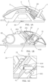
Figure 1A shows a side view of an example of a pointing device. -
Figure 1B shows a longitudinal section of the pointing device offigure 1A -
Figure 1C shows a detailed view of an adjusting mechanism of the pointing device offigures 1A and 1B . -
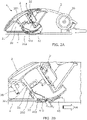
Figure 2A shows a longitudinal section of another example of a pointing device. -
Figure 2B shows a detailed view of the adjusting mechanism offigure 2A . -
Figure 2C shows the pointing device offigure 2A in two different positions of the adjusting mechanism. - Pointing devices have a geometry adapted to fit most users. Nonetheless, in the case of long-term users, e.g., game enthusiasts, a pointing device having an adjusting mechanism that allows the user to modify the shape of the pointing device to be more ergonomic or that fits the user better is desired. For example, a slightly missized pointing device may cause the user's hand to cramp or cause other discomfort when used for long periods of time.
- Examples of adjustable pointing devices are disclosed in
US6157370A ,US2005030278A1 andUS5870081 A . - In the foregoing, reference is made to the accompanying drawings. The examples in the description and drawings should be considered illustrative and are not to be considered as limiting to the specific example or element described. Multiple examples may be derived from the following description and/or drawings through modification, combination or variation of certain elements. Although certain features are shown and described in conjunction, they may be applied separately to the pointing devices of this description, also, if not specifically required to be included together. Furthermore, it may be understood that examples or elements that are not literally described may be derived from the description and drawings by a person of ordinary skill in the art.
-
Figures 1A, 1B and 1C show an example of a pointing device, in particular, a mouse, for use, e.g., in a computing system. In particular,figure 1A shows apointing device 1 having abase 4, agrip portion 2 installed on thebase 4 and auser input element 3 that may comprise elements such as a switches for performing click actions or any other type of mechanisms to acquire a user input. - Further, the
pointing device 1 comprises anadjusting mechanism 20 for modifying the shape of the pointing device to accommodate a user. In the example offigure 1A theadjusting mechanism 20 is to modify the separation distance between at least part of thegrip portion 2 and thebase 4. - In the example of
figure 1A , theadjusting mechanism 20 comprises a column intermediate to the base and the grip portion and interconnects the base to the grip portion. Therefore the column defines the separation distance between thegrip portion 2 and thebase 4, and such separation distance may be configurable by theadjusting mechanism 20. - Also, the
adjusting mechanism 20 comprises aswitch 40 adapted to lock the column at a determined separation distance. The switch may be located on thebase 4 of thepointing device 1. The location of theswitch 40 in the base allows for the user to actuate on it while being in the ergonomic position that he would take during the use of the device and, furthermore, allows one-handed operation of theswitch 40 and adjustment of the separation distance by the user. In the example offigure 1A , theswitch 40 is a switch that slides longitudinally along thebase 4, however, other types of switches, such as a push button that slides transversally along thebase 4, are envisaged. -
Figure 1B shows a cross section wherein the internal elements of thepointing device 1 are illustrated.Figure 1B shows in more detail the user input element that comprises ascroll wheel 30. - Further, the
adjusting mechanism 20 is shown in more detail wherein the column is a telescopic column, i.e., having anexternal body 202 that is fixed to thebase 4 and at least aninternal body 201 that is telescopic to theexternal body 202 with the ability to move with respect to it. -
Figure 1C shows a detailed view of an example wherein theadjusting mechanism 20 comprises a gear assembly to control the separation distance, i.e., the length of the column. In the example offigure 1B , the gear assembly is envisaged as aprimary toothed element 22 and asecondary toothed element 410. The secondary toothed element is complementary to the primary toothed element, i.e., having at least a tooth that fits between a pair of teeth of the primary toothed element. - In an example, a modification of the length of the column implies a relative movement in the gear assembly, in particular, between the primary and secondary toothed element. This may be accomplished, e.g., by attaching one of the primary or secondary toothed element to the
external body 202 of the column and the other to theinternal body 201. - In an embodiment, the gear assembly may be replaced by other types of equivalent mechanisms such as, for example, frictional engagement mechanisms and/or pin and lock engagement mechanisms.
- Also,
figures 1B and 1C show that the switch is connected to the gear assembly by means of a locking mechanism, in this case, arod 41. The locking mechanism may be, e.g., slidingly attached to the base and connected to theswitch 40. - The example of locking mechanism of
figures 1B and 1C is attached to the base, and upon a movement M, the switch may move from a locked position (as shown infigure 1C ) to an unlocked position wherein thesecondary toothed element 410 is displaced away from theprimary toothed element 22 thereby allowing it to move. This displacement may be a displacement that completely disengages the gear assembly or a displacement that partially disengages the gear assembly allowing it to move with certain restrictions. For example, therod 41 may have an elastic component that allows a movement of theprimary toothed element 22 if a force is exerted by the user causing thesecondary toothed element 410 to engage between a different set of teeth of theprimary toothed element 22. The example of the partial disengagement provides a feature wherein the column is moved in identifiable steps between pairs of teeth of theprimary toothed element 22 which facilitates the locking in a determined position by a user. - Also, the
adjusting mechanism 20 comprises anelastic member 21 to bias the column to extend, i.e., to increase the separation distance or to move thegrip portion 2 away from thebase 4. Elastic members can include, amongst others, springs, gas canisters, or any element capable of recovering size and shape after a deformation, for example, a deformation caused by a compressing force. - In an example, the
pointing device 1 may also comprise a second grip portion defined by theinput element 3. Such second grip portion may be installed to maintain a fixed distance with the base or may comprise separation distance adjusting means. For example, the second grip portion may also comprise a similar adjusting mechanism or may be attached to theadjusting mechanism 20 of thegrip portion 2. - In a further example, the
grip portion 2 may also be attached to the base by ahinge 5 located in an intermediate structure. The use of a hinge as a further attachment element (in addition to the column) allows for thegrip portion 2 to also rotate thereby accommodating the user and improving the ergonomics of the pointingdevice 1 by modifying the inclination of thegrip portion 2. For example, thehinge 5 may be located towards the center of thepointing device 1 to maintain the continuity of the shape near the center while allowing an end away from the center of thepointing device 1 to travel a large distance. -
Figures 2A, 2B and2C show another example of apointing device 1 also comprising agrip portion 2, aninput element 3 and anadjusting mechanism 20. - The
adjusting mechanism 20 of the example offigures 2A, 2B and2C is also a gear assembly wherein aprimary toothed element 22 is configured to engage asecondary toothed element 410. Theprimary toothed element 22 may be a section of a pinion, and thesecondary toothed element 410 may be a rack. - In particular,
figure 2A has a locking mechanism wherein a switch is connected to awedge 42. The wedge may be slidably attached to thebase 4. -
Figure 2B shows a detail of the locking mechanism and biasing elements provided in an example. In the example offigure 2B , a movement of thewedge 42 in an unlocking direction M causes the gear assembly to partially or completely disengage thereby allowing theprimary toothed element 22 to move relative to thesecondary toothed element 410. In the locked position (as shown infigure 2A ), the wedge pushes the secondary toothed element towards the primary toothed element so as to engage theprimary toothed element 22 thereby blocking the movement of theprimary toothed element 22 due to its attachment to thebase 4 by the action of thewedge 42. - Also, in the example of
figure 2B , several biasing elements are provided. Anelastic member 21 is provided, as in the examples offigure 1A, 1B, and 1C , for exerting a first biasing force B1 on thegrip portion 2 away from thebase 4. In this way, the user may unlock the locking mechanism, and thepointing device 1 may be biased towards its most voluminous geometry. The user may decrease the volume of the pointing device by pushing thegrip portion 2 towards thebase 4. - Another biasing element may be provided on the second
toothed element 410 so that the secondtoothed element 410 is provided with an elastic component that exerts a second biasing force B2 to disengage from the primarytoothed element 22 thereby allowing a relative movement between the primarytoothed element 22 and the secondarytoothed element 410 when the switch is the unlocked position, i.e., the second biasing force B2 allows for, at least, a partial disengagement of the gear assembly when the switch is in the unlocked position, thereby allowing a user to modify the relative distances between the elements of the gear assembly. This may be accomplished by embedding or manufacturing the secondary toothed element with an elastic material (as may be the case for the secondary toothed element offigures 1A, 1B, and 1C ) or by adding a spring-like element attached to the secondarytoothed element 410 or to its associatedhinge 411. - A further biasing element may be provided on the
wedge 42, for example, to bias it towards the locked position, i.e., a direction opposite to the unlocking direction M. -
Figure 2C shows apointing device 1 according to an example wherein the pointing device is shown in two possible positions to adapt to different users, e.g., to accommodate their ergonomics. In a first position, drawn in solid lines, thewedge 42 locks theadjusting mechanism 20 in a position wherein the pointing device occupies a larger volume. In a second position, shown in dashed lines, the pointing device is adjusted by the adjustingmechanism 20 to occupy a smaller volume. - In the first position, an extended grip portion 2' of the
pointing device 1 is achieved by biasing the grip portion away from thebase 4 by an elongated elastic member 21' being such elongated elastic member 21' in an elongated position. Also, the primary toothed element 22' is engaged with the secondarytoothed element 410 by engaging some of the teeth of the primary toothed element 22' between corresponding teeth of the secondarytoothed element 410. Given that thewedge 42 is in the locked position (pushing the primary toothed element 22' and the secondarytoothed element 410 together) a pushing force of the user on the grip portion 2' would not modify the position of the adjusting mechanism, i.e., would not modify the position of the elongated elastic member 21'. - A movement of the wedge in the unlocking direction M, and, optionally a biasing force in the associated
hinge 411 of the secondarytoothed element 410 causes the gear assembly to, at least, partially disengage and allow a change in the relative position between the primary toothed element 22' and the secondarytoothed element 410. - For example, a pushing force of the elongated grip portion 2' may cause a compression on the elongated elastic member 21' thereby achieving the movement of the grip portion to a
compressed grip portion 2" wherein the elastic member is now a compressedelastic member 21". As can be seen forfigure 2C , there is a change in the relative position between the gear assembly, i.e., between the primary toothed element 22' and the secondarytoothed element 410 corresponding to the elongated grip portion 2' and the relative position corresponding to thecompressed grip portion 2". - While the grip portion is in the form of a
compressed grip portion 2" and thewedge 42 is in the locked position, the gear assembly is locked, thereby preventing the elastic member from further compressing or elongating. - An adjustable pointing device, such as a mouse, is disclosed that comprises a base, a grip portion installed on the base, and an adjusting mechanism to define a separation distance between the base and the grip portion, the adjusting mechanism comprising:
- a column intermediate to the base and the grip portion, the column thereby defining the separation distance;
- a locking assembly having a primary toothed element with several teeth and a secondary toothed element with at least one tooth complementary to the teeth of the primary toothed element;
- According to the invention, the column comprises an elastic member, for example, a spring like element that may have at least one elongated position and a compressed position. Furthermore, the elastic member is to bias the column away from the base.
- In a further example, at least one of the primary toothed element or the secondary toothed element is a pinion or a section of a pinion. Also, at least one of the primary toothed element or the secondary toothed element may be, e.g., a rack.
- As for the switch, it may be attached to the base, and it may be slidable between a locked position and an unlocked position. The switch may also be located on the base. In the locked position, the switch may lock the relative position between the primary toothed element and the secondary toothed element by connecting at least one of the primary toothed element or the secondary toothed element to the base. This may be achieved by acting as an intermediary to engage the primary toothed element to a secondary toothed element that is connected to the base.
- In an example, to further change the geometry of the device not only by occupying a different volume but also by performing other changes on the geometry of the pointing device, the grip portion may comprise a hinge attached to a structural element of the pointing device, i.e., an element fixed with respect to the base. The hinge may be to modify the inclination of the grip portion with respect to the base.
- Furthermore, the device may comprise a second grip portion installed on the base. The second grip portion may be, e.g., fixedly attached to the base and comprise the controls for user input such as switches, scroll wheels, etc.
- Also, an adjustable pointing device is disclosed wherein it comprises a base, a grip portion, and an adjusting mechanism, the grip portion being attached to the base by the adjusting mechanism wherein the adjusting mechanism comprises an elastic member biasing the grip portion away from the base and comprising a locking mechanism movable between a locked position in which the locking mechanism is to prevent the grip portion from moving relative to the base and an unlocked position in which the locking mechanism is to allow the grip portion to move relative to the base.
- A modification of the relative position between the grip portion and the base may, for example, cause a relative movement on a gear assembly, i.e., between a primary toothed element and a secondary toothed element of the gear assembly. Also, the locking mechanism may be provided to, while in the locked position, block the gear mechanism and prevent the movement between the grip portion and the base.
- The primary toothed element and/or the secondary toothed element may be a pinion or a rack and the locking mechanism may be to engage and, at least, partially disengage the gear assembly and may be slidably attached to the base.
Claims (10)
- An adjustable pointing device (1) that comprises a base (4), a grip portion (2) installed on the base (4), and an adjusting mechanism (20) to define a separation distance between the base (4) and the grip portion (2), the adjusting mechanism (20) characterised by:• a column intermediate to the base (4) and the grip portion (2), the column thereby defining the separation distance, the column comprising an elastic member (21) to bias the grip portion (2) away from the base (4);• a locking assembly having a primary toothed element (22) with several teeth and a secondary toothed element (410) with at least one tooth complementary to the teeth of the primary toothed element (22);wherein the locking assembly is attached to the column so that a modification of the separation distance causes a relative movement between the primary toothed element (22) and the secondary toothed element (410), andwherein the adjusting mechanism (20) further comprises a switch (40) to lock the relative position between the primary toothed element (22) and the secondary toothed element (410) and prevent the elastic member (21) from biasing the grip portion (2) away from the base (4).
- The adjustable pointing device (1) of claim 1, wherein at least one of the primary toothed element (22) or the secondary toothed element (410) is a pinion.
- The adjustable pointing device (1) of claim 1, wherein at least one of the primary toothed element (22) or the secondary toothed element (410) is a rack.
- The adjustable pointing device (1) of claim 1, wherein the switch (40) is attached to the base (4) and the switch (40) is slidable between a locked position and an unlocked position.
- The adjustable pointing device (1) of claim 4, wherein, in the locked position, the switch (40) locks the relative position between the primary toothed element (22) and the secondary toothed element (410) by connecting at least one of the primary toothed element (22) or the secondary toothed element (410) to the base (4).
- The adjustable pointing device (1) of claim 1, wherein the switch (40) is located on the base (4).
- The adjustable pointing device (1) of claim 1, wherein the grip portion (2) further comprises a hinge (5) for attachment to the base (4), and wherein the hinge (5) is to modify the inclination of the grip portion (2).
- The adjustable pointing device (1) of claim 1, wherein the adjustable pointing device (1) further comprises a second grip portion installed on the base (4).
- The adjustable pointing device (1) of claim 8, wherein the second grip portion is fixedly attached to the base (4).
- The adjustable pointing device (1) of claim 8 or claim 9, wherein the second grip portion (3) comprises controls for user input.
Applications Claiming Priority (1)
| Application Number | Priority Date | Filing Date | Title |
|---|---|---|---|
| PCT/US2017/067850 WO2019125458A1 (en) | 2017-12-21 | 2017-12-21 | Adjustable pointing devices |
Publications (3)
| Publication Number | Publication Date |
|---|---|
| EP3673349A1 EP3673349A1 (en) | 2020-07-01 |
| EP3673349A4 EP3673349A4 (en) | 2021-04-21 |
| EP3673349B1 true EP3673349B1 (en) | 2023-03-01 |
Family
ID=66993691
Family Applications (1)
| Application Number | Title | Priority Date | Filing Date |
|---|---|---|---|
| EP17935666.2A Active EP3673349B1 (en) | 2017-12-21 | 2017-12-21 | Adjustable pointing devices |
Country Status (5)
| Country | Link |
|---|---|
| US (1) | US11119586B2 (en) |
| EP (1) | EP3673349B1 (en) |
| CN (1) | CN111373352B (en) |
| TW (1) | TWI695254B (en) |
| WO (1) | WO2019125458A1 (en) |
Families Citing this family (2)
| Publication number | Priority date | Publication date | Assignee | Title |
|---|---|---|---|---|
| US12416981B2 (en) * | 2023-07-17 | 2025-09-16 | Han Kiel Lee | Computer mouse |
| US12554346B2 (en) * | 2024-07-19 | 2026-02-17 | Microsoft Technology Licensing, Llc | Adjustable computer mouse |
Family Cites Families (28)
| Publication number | Priority date | Publication date | Assignee | Title |
|---|---|---|---|---|
| US5260696A (en) * | 1991-02-19 | 1993-11-09 | Maynard Jr Stuart T | Multiple signaling mouse with faceted surfaces |
| USD372906S (en) | 1995-05-09 | 1996-08-20 | Alps Electric (Usa) Inc. | Adjustable mouse |
| US6157370A (en) * | 1996-01-03 | 2000-12-05 | Softview Computer Products Corp. | Ergonomic mouse extension |
| TW299862U (en) | 1996-08-28 | 1997-03-01 | Transpacific Plasma Llc | Case structure of mouse |
| US5870081A (en) * | 1996-10-03 | 1999-02-09 | Primax Electronics Ltd. | Mouse housing structure |
| USD405072S (en) | 1997-12-23 | 1999-02-02 | Kye Systems Corp. | Multidimensional mouse |
| USD411189S (en) | 1998-04-24 | 1999-06-22 | Kye Systems Corp. | Computer mouse |
| USD426216S (en) | 1999-07-06 | 2000-06-06 | Sejin Electron Inc. | Mouse |
| US7109972B2 (en) * | 2003-08-08 | 2006-09-19 | Liang Fu | Adjustable pointing and control device with automatic handedness switch |
| US7227533B2 (en) | 2003-12-19 | 2007-06-05 | Kye Systems Corp. | Height adjustable computer input device |
| USD505677S1 (en) | 2004-02-10 | 2005-05-31 | Logitech Europe S.A. | Computer mouse |
| TWI287734B (en) | 2005-08-12 | 2007-10-01 | Darfon Electronics Corp | Adjustable mouse |
| JP2009282565A (en) | 2008-05-19 | 2009-12-03 | Toshiba Corp | Mouse device and information processing system |
| CN201378302Y (en) | 2008-12-01 | 2010-01-06 | 方祺 | Adjustable mouse |
| CN201489470U (en) | 2009-08-18 | 2010-05-26 | 邱亮 | Compressive lifting mouse |
| CN201622542U (en) * | 2010-04-29 | 2010-11-03 | 李伟成 | Health-care type mouse |
| US8614677B2 (en) * | 2010-11-02 | 2013-12-24 | Giga-Byte Technology Co., Ltd. | Mouse with adjustable switch |
| SE537583C2 (en) * | 2012-01-05 | 2015-06-30 | Gunnar Drougge Ab | Computer mouse with adjustable lid |
| CN103365435B (en) | 2012-03-26 | 2017-07-21 | 富泰华工业(深圳)有限公司 | mouse |
| CN103870025A (en) * | 2012-12-18 | 2014-06-18 | 郑国书 | Mouse device capable of adjusting return elasticity of press key |
| JP3183747U (en) * | 2013-03-18 | 2013-05-30 | 寶トク科技股フン有限公司 | Handheld input device with adjustable vane |
| CN203465682U (en) | 2013-08-19 | 2014-03-05 | 西安蒙德信息技术有限公司 | Novel mouse with adjustable height |
| TWD161004S (en) | 2013-10-09 | 2014-06-11 | 艾維克科技股份有限公司 | mouse |
| TWI522851B (en) * | 2013-11-19 | 2016-02-21 | 艾維克科技股份有限公司 | Adjustable grip mouse |
| USD718310S1 (en) | 2013-12-18 | 2014-11-25 | Zalman Tech Co., Ltd. | Computer mouse |
| USD744485S1 (en) | 2014-11-18 | 2015-12-01 | Mad Catz Interactive, Inc. | Mouse user interface with configurable components |
| CN105739725B (en) * | 2016-01-22 | 2018-12-14 | 周勇 | Mouse |
| CN107300989B (en) * | 2016-04-15 | 2020-07-24 | 东莞宝德电子有限公司 | Mouse with adjustable hand rest |
-
2017
- 2017-12-21 WO PCT/US2017/067850 patent/WO2019125458A1/en not_active Ceased
- 2017-12-21 EP EP17935666.2A patent/EP3673349B1/en active Active
- 2017-12-21 US US16/648,835 patent/US11119586B2/en active Active
- 2017-12-21 CN CN201780097135.6A patent/CN111373352B/en active Active
-
2018
- 2018-11-26 TW TW107142076A patent/TWI695254B/en active
Also Published As
| Publication number | Publication date |
|---|---|
| US11119586B2 (en) | 2021-09-14 |
| WO2019125458A1 (en) | 2019-06-27 |
| EP3673349A1 (en) | 2020-07-01 |
| TWI695254B (en) | 2020-06-01 |
| CN111373352A (en) | 2020-07-03 |
| EP3673349A4 (en) | 2021-04-21 |
| CN111373352B (en) | 2024-03-05 |
| US20200310560A1 (en) | 2020-10-01 |
| TW201931053A (en) | 2019-08-01 |
Similar Documents
| Publication | Publication Date | Title |
|---|---|---|
| US9746281B2 (en) | Latch and release mechanism for adjustable firearm stock | |
| US11119586B2 (en) | Adjustable pointing devices | |
| EP3488733B1 (en) | Slide rail assembly and rail kit thereof | |
| EP3374005B1 (en) | Activation mechanism for a medicament delivery device and a medicament delivery device comprising the activation mechanism | |
| US20170340836A1 (en) | A Multi-State Ratchet Mechanism for Drug Injection Devices | |
| EP3440961B1 (en) | Slide rail assembly and rail kit thereof | |
| US20050030278A1 (en) | Adjustable pointing and control device with automatic handedness switch | |
| US10029596B2 (en) | Retaining device for vehicle headrests | |
| US10310633B2 (en) | Mouse device | |
| KR102016648B1 (en) | Armrest multi stage rotation and height controllig apparatus of a chair | |
| CN110290974A (en) | Mechanical device for adjusting the distance between two elements | |
| JP4022109B2 (en) | Slide rail with unlock function | |
| CN109484260A (en) | Safety belt anti-error-touch device and child safety seat | |
| EP2986183B1 (en) | A chair adjustment device | |
| JP2017172219A (en) | Telescopic lock device in telescopic leg device | |
| US20170207041A1 (en) | Adjustable ergonomic keyboard | |
| TWI779829B (en) | Hand controller assembly | |
| KR101476304B1 (en) | tilt lever for tilting apparatus of steering column | |
| JP2017036624A (en) | Extendable leg device | |
| US20260041596A1 (en) | Rapidly adjustable walking stick and forearm crutch | |
| US9119452B1 (en) | Handle structure for a draw bar of a luggage case | |
| CN207156997U (en) | Safety belt anti-error-touch device and child safety seat | |
| EP3925473B1 (en) | Closure buckle for a strap of a protective helmet and closing method for a strap of a protective helmet | |
| EP3375316B1 (en) | Connection buckle for seats belts | |
| US12117875B1 (en) | Laptop computer including an integrated support device |
Legal Events
| Date | Code | Title | Description |
|---|---|---|---|
| STAA | Information on the status of an ep patent application or granted ep patent |
Free format text: STATUS: THE INTERNATIONAL PUBLICATION HAS BEEN MADE |
|
| PUAI | Public reference made under article 153(3) epc to a published international application that has entered the european phase |
Free format text: ORIGINAL CODE: 0009012 |
|
| STAA | Information on the status of an ep patent application or granted ep patent |
Free format text: STATUS: REQUEST FOR EXAMINATION WAS MADE |
|
| 17P | Request for examination filed |
Effective date: 20200326 |
|
| AK | Designated contracting states |
Kind code of ref document: A1 Designated state(s): AL AT BE BG CH CY CZ DE DK EE ES FI FR GB GR HR HU IE IS IT LI LT LU LV MC MK MT NL NO PL PT RO RS SE SI SK SM TR |
|
| AX | Request for extension of the european patent |
Extension state: BA ME |
|
| DAV | Request for validation of the european patent (deleted) | ||
| DAX | Request for extension of the european patent (deleted) | ||
| A4 | Supplementary search report drawn up and despatched |
Effective date: 20210322 |
|
| RIC1 | Information provided on ipc code assigned before grant |
Ipc: G06F 3/0354 20130101AFI20210316BHEP |
|
| GRAP | Despatch of communication of intention to grant a patent |
Free format text: ORIGINAL CODE: EPIDOSNIGR1 |
|
| STAA | Information on the status of an ep patent application or granted ep patent |
Free format text: STATUS: GRANT OF PATENT IS INTENDED |
|
| INTG | Intention to grant announced |
Effective date: 20221111 |
|
| RIN1 | Information on inventor provided before grant (corrected) |
Inventor name: HSIAO, SHUCHUN Inventor name: CERNY, GREG Inventor name: WONG, GLENN A. Inventor name: PATIL, RAHUL Inventor name: ZARNOWITZ, ARTHUR H. |
|
| GRAS | Grant fee paid |
Free format text: ORIGINAL CODE: EPIDOSNIGR3 |
|
| GRAA | (expected) grant |
Free format text: ORIGINAL CODE: 0009210 |
|
| STAA | Information on the status of an ep patent application or granted ep patent |
Free format text: STATUS: THE PATENT HAS BEEN GRANTED |
|
| AK | Designated contracting states |
Kind code of ref document: B1 Designated state(s): AL AT BE BG CH CY CZ DE DK EE ES FI FR GB GR HR HU IE IS IT LI LT LU LV MC MK MT NL NO PL PT RO RS SE SI SK SM TR |
|
| REG | Reference to a national code |
Ref country code: GB Ref legal event code: FG4D |
|
| REG | Reference to a national code |
Ref country code: CH Ref legal event code: EP Ref country code: AT Ref legal event code: REF Ref document number: 1551449 Country of ref document: AT Kind code of ref document: T Effective date: 20230315 |
|
| REG | Reference to a national code |
Ref country code: DE Ref legal event code: R096 Ref document number: 602017066536 Country of ref document: DE |
|
| REG | Reference to a national code |
Ref country code: IE Ref legal event code: FG4D |
|
| REG | Reference to a national code |
Ref country code: LT Ref legal event code: MG9D |
|
| REG | Reference to a national code |
Ref country code: NL Ref legal event code: MP Effective date: 20230301 |
|
| PG25 | Lapsed in a contracting state [announced via postgrant information from national office to epo] |
Ref country code: RS Free format text: LAPSE BECAUSE OF FAILURE TO SUBMIT A TRANSLATION OF THE DESCRIPTION OR TO PAY THE FEE WITHIN THE PRESCRIBED TIME-LIMIT Effective date: 20230301 Ref country code: NO Free format text: LAPSE BECAUSE OF FAILURE TO SUBMIT A TRANSLATION OF THE DESCRIPTION OR TO PAY THE FEE WITHIN THE PRESCRIBED TIME-LIMIT Effective date: 20230601 Ref country code: LV Free format text: LAPSE BECAUSE OF FAILURE TO SUBMIT A TRANSLATION OF THE DESCRIPTION OR TO PAY THE FEE WITHIN THE PRESCRIBED TIME-LIMIT Effective date: 20230301 Ref country code: LT Free format text: LAPSE BECAUSE OF FAILURE TO SUBMIT A TRANSLATION OF THE DESCRIPTION OR TO PAY THE FEE WITHIN THE PRESCRIBED TIME-LIMIT Effective date: 20230301 Ref country code: HR Free format text: LAPSE BECAUSE OF FAILURE TO SUBMIT A TRANSLATION OF THE DESCRIPTION OR TO PAY THE FEE WITHIN THE PRESCRIBED TIME-LIMIT Effective date: 20230301 Ref country code: ES Free format text: LAPSE BECAUSE OF FAILURE TO SUBMIT A TRANSLATION OF THE DESCRIPTION OR TO PAY THE FEE WITHIN THE PRESCRIBED TIME-LIMIT Effective date: 20230301 |
|
| REG | Reference to a national code |
Ref country code: AT Ref legal event code: MK05 Ref document number: 1551449 Country of ref document: AT Kind code of ref document: T Effective date: 20230301 |
|
| PG25 | Lapsed in a contracting state [announced via postgrant information from national office to epo] |
Ref country code: SE Free format text: LAPSE BECAUSE OF FAILURE TO SUBMIT A TRANSLATION OF THE DESCRIPTION OR TO PAY THE FEE WITHIN THE PRESCRIBED TIME-LIMIT Effective date: 20230301 Ref country code: PL Free format text: LAPSE BECAUSE OF FAILURE TO SUBMIT A TRANSLATION OF THE DESCRIPTION OR TO PAY THE FEE WITHIN THE PRESCRIBED TIME-LIMIT Effective date: 20230301 Ref country code: NL Free format text: LAPSE BECAUSE OF FAILURE TO SUBMIT A TRANSLATION OF THE DESCRIPTION OR TO PAY THE FEE WITHIN THE PRESCRIBED TIME-LIMIT Effective date: 20230301 Ref country code: GR Free format text: LAPSE BECAUSE OF FAILURE TO SUBMIT A TRANSLATION OF THE DESCRIPTION OR TO PAY THE FEE WITHIN THE PRESCRIBED TIME-LIMIT Effective date: 20230602 Ref country code: FI Free format text: LAPSE BECAUSE OF FAILURE TO SUBMIT A TRANSLATION OF THE DESCRIPTION OR TO PAY THE FEE WITHIN THE PRESCRIBED TIME-LIMIT Effective date: 20230301 |
|
| PG25 | Lapsed in a contracting state [announced via postgrant information from national office to epo] |
Ref country code: SM Free format text: LAPSE BECAUSE OF FAILURE TO SUBMIT A TRANSLATION OF THE DESCRIPTION OR TO PAY THE FEE WITHIN THE PRESCRIBED TIME-LIMIT Effective date: 20230301 Ref country code: RO Free format text: LAPSE BECAUSE OF FAILURE TO SUBMIT A TRANSLATION OF THE DESCRIPTION OR TO PAY THE FEE WITHIN THE PRESCRIBED TIME-LIMIT Effective date: 20230301 Ref country code: PT Free format text: LAPSE BECAUSE OF FAILURE TO SUBMIT A TRANSLATION OF THE DESCRIPTION OR TO PAY THE FEE WITHIN THE PRESCRIBED TIME-LIMIT Effective date: 20230703 Ref country code: EE Free format text: LAPSE BECAUSE OF FAILURE TO SUBMIT A TRANSLATION OF THE DESCRIPTION OR TO PAY THE FEE WITHIN THE PRESCRIBED TIME-LIMIT Effective date: 20230301 Ref country code: CZ Free format text: LAPSE BECAUSE OF FAILURE TO SUBMIT A TRANSLATION OF THE DESCRIPTION OR TO PAY THE FEE WITHIN THE PRESCRIBED TIME-LIMIT Effective date: 20230301 Ref country code: AT Free format text: LAPSE BECAUSE OF FAILURE TO SUBMIT A TRANSLATION OF THE DESCRIPTION OR TO PAY THE FEE WITHIN THE PRESCRIBED TIME-LIMIT Effective date: 20230301 |
|
| PG25 | Lapsed in a contracting state [announced via postgrant information from national office to epo] |
Ref country code: SK Free format text: LAPSE BECAUSE OF FAILURE TO SUBMIT A TRANSLATION OF THE DESCRIPTION OR TO PAY THE FEE WITHIN THE PRESCRIBED TIME-LIMIT Effective date: 20230301 Ref country code: IS Free format text: LAPSE BECAUSE OF FAILURE TO SUBMIT A TRANSLATION OF THE DESCRIPTION OR TO PAY THE FEE WITHIN THE PRESCRIBED TIME-LIMIT Effective date: 20230701 |
|
| REG | Reference to a national code |
Ref country code: DE Ref legal event code: R097 Ref document number: 602017066536 Country of ref document: DE |
|
| PLBE | No opposition filed within time limit |
Free format text: ORIGINAL CODE: 0009261 |
|
| STAA | Information on the status of an ep patent application or granted ep patent |
Free format text: STATUS: NO OPPOSITION FILED WITHIN TIME LIMIT |
|
| PG25 | Lapsed in a contracting state [announced via postgrant information from national office to epo] |
Ref country code: SI Free format text: LAPSE BECAUSE OF FAILURE TO SUBMIT A TRANSLATION OF THE DESCRIPTION OR TO PAY THE FEE WITHIN THE PRESCRIBED TIME-LIMIT Effective date: 20230301 Ref country code: DK Free format text: LAPSE BECAUSE OF FAILURE TO SUBMIT A TRANSLATION OF THE DESCRIPTION OR TO PAY THE FEE WITHIN THE PRESCRIBED TIME-LIMIT Effective date: 20230301 |
|
| 26N | No opposition filed |
Effective date: 20231204 |
|
| PG25 | Lapsed in a contracting state [announced via postgrant information from national office to epo] |
Ref country code: IT Free format text: LAPSE BECAUSE OF FAILURE TO SUBMIT A TRANSLATION OF THE DESCRIPTION OR TO PAY THE FEE WITHIN THE PRESCRIBED TIME-LIMIT Effective date: 20230301 |
|
| REG | Reference to a national code |
Ref country code: CH Ref legal event code: PL |
|
| PG25 | Lapsed in a contracting state [announced via postgrant information from national office to epo] |
Ref country code: LU Free format text: LAPSE BECAUSE OF NON-PAYMENT OF DUE FEES Effective date: 20231221 |
|
| PG25 | Lapsed in a contracting state [announced via postgrant information from national office to epo] |
Ref country code: MC Free format text: LAPSE BECAUSE OF FAILURE TO SUBMIT A TRANSLATION OF THE DESCRIPTION OR TO PAY THE FEE WITHIN THE PRESCRIBED TIME-LIMIT Effective date: 20230301 |
|
| GBPC | Gb: european patent ceased through non-payment of renewal fee |
Effective date: 20231221 |
|
| REG | Reference to a national code |
Ref country code: BE Ref legal event code: MM Effective date: 20231231 |
|
| PG25 | Lapsed in a contracting state [announced via postgrant information from national office to epo] |
Ref country code: MC Free format text: LAPSE BECAUSE OF FAILURE TO SUBMIT A TRANSLATION OF THE DESCRIPTION OR TO PAY THE FEE WITHIN THE PRESCRIBED TIME-LIMIT Effective date: 20230301 Ref country code: LU Free format text: LAPSE BECAUSE OF NON-PAYMENT OF DUE FEES Effective date: 20231221 |
|
| REG | Reference to a national code |
Ref country code: IE Ref legal event code: MM4A |
|
| PG25 | Lapsed in a contracting state [announced via postgrant information from national office to epo] |
Ref country code: IE Free format text: LAPSE BECAUSE OF NON-PAYMENT OF DUE FEES Effective date: 20231221 |
|
| PG25 | Lapsed in a contracting state [announced via postgrant information from national office to epo] |
Ref country code: GB Free format text: LAPSE BECAUSE OF NON-PAYMENT OF DUE FEES Effective date: 20231221 |
|
| PG25 | Lapsed in a contracting state [announced via postgrant information from national office to epo] |
Ref country code: BE Free format text: LAPSE BECAUSE OF NON-PAYMENT OF DUE FEES Effective date: 20231231 |
|
| PG25 | Lapsed in a contracting state [announced via postgrant information from national office to epo] |
Ref country code: FR Free format text: LAPSE BECAUSE OF NON-PAYMENT OF DUE FEES Effective date: 20231231 |
|
| PG25 | Lapsed in a contracting state [announced via postgrant information from national office to epo] |
Ref country code: CH Free format text: LAPSE BECAUSE OF NON-PAYMENT OF DUE FEES Effective date: 20231231 |
|
| PG25 | Lapsed in a contracting state [announced via postgrant information from national office to epo] |
Ref country code: IE Free format text: LAPSE BECAUSE OF NON-PAYMENT OF DUE FEES Effective date: 20231221 Ref country code: GB Free format text: LAPSE BECAUSE OF NON-PAYMENT OF DUE FEES Effective date: 20231221 Ref country code: FR Free format text: LAPSE BECAUSE OF NON-PAYMENT OF DUE FEES Effective date: 20231231 Ref country code: CH Free format text: LAPSE BECAUSE OF NON-PAYMENT OF DUE FEES Effective date: 20231231 Ref country code: BE Free format text: LAPSE BECAUSE OF NON-PAYMENT OF DUE FEES Effective date: 20231231 |
|
| PG25 | Lapsed in a contracting state [announced via postgrant information from national office to epo] |
Ref country code: BG Free format text: LAPSE BECAUSE OF FAILURE TO SUBMIT A TRANSLATION OF THE DESCRIPTION OR TO PAY THE FEE WITHIN THE PRESCRIBED TIME-LIMIT Effective date: 20230301 |
|
| PG25 | Lapsed in a contracting state [announced via postgrant information from national office to epo] |
Ref country code: BG Free format text: LAPSE BECAUSE OF FAILURE TO SUBMIT A TRANSLATION OF THE DESCRIPTION OR TO PAY THE FEE WITHIN THE PRESCRIBED TIME-LIMIT Effective date: 20230301 |
|
| PG25 | Lapsed in a contracting state [announced via postgrant information from national office to epo] |
Ref country code: CY Free format text: LAPSE BECAUSE OF FAILURE TO SUBMIT A TRANSLATION OF THE DESCRIPTION OR TO PAY THE FEE WITHIN THE PRESCRIBED TIME-LIMIT; INVALID AB INITIO Effective date: 20171221 |
|
| PG25 | Lapsed in a contracting state [announced via postgrant information from national office to epo] |
Ref country code: HU Free format text: LAPSE BECAUSE OF FAILURE TO SUBMIT A TRANSLATION OF THE DESCRIPTION OR TO PAY THE FEE WITHIN THE PRESCRIBED TIME-LIMIT; INVALID AB INITIO Effective date: 20171221 |
|
| PG25 | Lapsed in a contracting state [announced via postgrant information from national office to epo] |
Ref country code: TR Free format text: LAPSE BECAUSE OF FAILURE TO SUBMIT A TRANSLATION OF THE DESCRIPTION OR TO PAY THE FEE WITHIN THE PRESCRIBED TIME-LIMIT Effective date: 20230301 |
|
| PGFP | Annual fee paid to national office [announced via postgrant information from national office to epo] |
Ref country code: DE Payment date: 20251126 Year of fee payment: 9 |