EP3673275B1 - Over the air calibration and testing of beamforming-based multi-antenna devices in anechoic and non-anechoic environments - Google Patents
Over the air calibration and testing of beamforming-based multi-antenna devices in anechoic and non-anechoic environments Download PDFInfo
- Publication number
- EP3673275B1 EP3673275B1 EP17762062.2A EP17762062A EP3673275B1 EP 3673275 B1 EP3673275 B1 EP 3673275B1 EP 17762062 A EP17762062 A EP 17762062A EP 3673275 B1 EP3673275 B1 EP 3673275B1
- Authority
- EP
- European Patent Office
- Prior art keywords
- under test
- device under
- antenna
- signaling information
- dut
- Prior art date
- Legal status (The legal status is an assumption and is not a legal conclusion. Google has not performed a legal analysis and makes no representation as to the accuracy of the status listed.)
- Active
Links
Images







Classifications
-
- H—ELECTRICITY
- H04—ELECTRIC COMMUNICATION TECHNIQUE
- H04B—TRANSMISSION
- H04B17/00—Monitoring; Testing
- H04B17/10—Monitoring; Testing of transmitters
- H04B17/15—Performance testing
- H04B17/191—Over-the-air testing
-
- G—PHYSICS
- G01—MEASURING; TESTING
- G01R—MEASURING ELECTRIC VARIABLES; MEASURING MAGNETIC VARIABLES
- G01R29/00—Arrangements for measuring or indicating electric quantities not covered by groups G01R19/00 - G01R27/00
- G01R29/08—Measuring electromagnetic field characteristics
- G01R29/10—Radiation diagrams of antennas
- G01R29/105—Radiation diagrams of antennas using anechoic chambers; Chambers or open field sites used therefor
-
- G—PHYSICS
- G01—MEASURING; TESTING
- G01R—MEASURING ELECTRIC VARIABLES; MEASURING MAGNETIC VARIABLES
- G01R29/00—Arrangements for measuring or indicating electric quantities not covered by groups G01R19/00 - G01R27/00
- G01R29/08—Measuring electromagnetic field characteristics
- G01R29/10—Radiation diagrams of antennas
-
- H—ELECTRICITY
- H04—ELECTRIC COMMUNICATION TECHNIQUE
- H04B—TRANSMISSION
- H04B17/00—Monitoring; Testing
- H04B17/10—Monitoring; Testing of transmitters
- H04B17/11—Monitoring; Testing of transmitters for calibration
- H04B17/12—Monitoring; Testing of transmitters for calibration of transmit antennas, e.g. of the amplitude or phase
-
- H—ELECTRICITY
- H04—ELECTRIC COMMUNICATION TECHNIQUE
- H04B—TRANSMISSION
- H04B17/00—Monitoring; Testing
- H04B17/20—Monitoring; Testing of receivers
- H04B17/21—Monitoring; Testing of receivers for calibration; for correcting measurements
- H04B17/22—Monitoring; Testing of receivers for calibration; for correcting measurements for calibration of the receiver components
- H04B17/221—Monitoring; Testing of receivers for calibration; for correcting measurements for calibration of the receiver components of receiver antennas, e.g. as to amplitude or phase
-
- H—ELECTRICITY
- H04—ELECTRIC COMMUNICATION TECHNIQUE
- H04B—TRANSMISSION
- H04B17/00—Monitoring; Testing
- H04B17/20—Monitoring; Testing of receivers
- H04B17/29—Performance testing
-
- H—ELECTRICITY
- H04—ELECTRIC COMMUNICATION TECHNIQUE
- H04B—TRANSMISSION
- H04B7/00—Radio transmission systems, i.e. using radiation field
- H04B7/02—Diversity systems; Multi-antenna system, i.e. transmission or reception using multiple antennas
- H04B7/04—Diversity systems; Multi-antenna system, i.e. transmission or reception using multiple antennas using two or more spaced independent antennas
- H04B7/0413—MIMO systems
-
- H—ELECTRICITY
- H04—ELECTRIC COMMUNICATION TECHNIQUE
- H04B—TRANSMISSION
- H04B7/00—Radio transmission systems, i.e. using radiation field
- H04B7/02—Diversity systems; Multi-antenna system, i.e. transmission or reception using multiple antennas
- H04B7/04—Diversity systems; Multi-antenna system, i.e. transmission or reception using multiple antennas using two or more spaced independent antennas
- H04B7/08—Diversity systems; Multi-antenna system, i.e. transmission or reception using multiple antennas using two or more spaced independent antennas at the receiving station
- H04B7/0837—Diversity systems; Multi-antenna system, i.e. transmission or reception using multiple antennas using two or more spaced independent antennas at the receiving station using pre-detection combining
- H04B7/0842—Weighted combining
- H04B7/086—Weighted combining using weights depending on external parameters, e.g. direction of arrival [DOA], predetermined weights or beamforming
Definitions
- Embodiments relate to a method for wirelessly calibrating a multi-antenna transceiver of a device under test, and in detail, to a method for wirelessly calibrating a beamforming network and/or a transceiver module (Rx module and/or Tx module) of the device under test. Some embodiments relate to calibration and testing of hybrid analog/digital beamforming-based multi-antenna devices in anechoic and non-anechoic environments.
- Wireless communication devices equipped with multiple antennas have to be calibrated and tested with respect to overall performance and conformance.
- a well-known method for device testing is the so-called conducted test (CT) where the device' antennas are disconnected from the device under test (DUT) and a device tester is directly connected to the DUT.
- CT conducted test
- DUT device under test
- a device tester is directly connected to the DUT.
- This test setup in its simple manner does not consider the DUT' antenna radiation patterns during the device testing.
- a major drawback of the conducted test is that any kind of beamforming/beam-processing algorithms implemented in the DUT cannot be evaluated, as all signals "virtually" impinge at the same direction. Moreover, no direction- or frequency-dependent signal amplification or attenuation may be noticeable as the DUT' antennas are not present in this test.
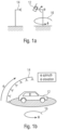
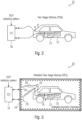
- Figs. 1a, 1b and 2 An extension of the conducted test is the so called two-stage method (TSM) [1], see Figs. 1a, 1b and 2 .
- Fig. 1a and 1b show schematic views of antenna measurement principles for small devices and for large devices, respectively.
- Fig. 2 shows a schematic view of a calibration/test setup 10 for the TSM.
- the DUT' 12 antenna radiation patterns are measured at a first stage ( Fig. 1a and 1b ) in an antenna measurement chamber where the DUT' antennas are rotated 16 such that a desired azimuth and elevation angle range is covered.
- the DUT 12 When the size of the DUT 12 is too large to be rotated in all desired angular directions, it can be put onto a turntable to cover the azimuth angles by rotating the DUT 12; the elevation angles are covered by movement of the transmitter antenna or by switching the active antenna on an antenna arc, cf. Fig. 1 .
- a conducted test between the device tester (e.g. eNodeB) and the DUT 12 is performed (see Fig. 2 ).
- the DUT' antenna radiation patterns and the MIMO propagation channel are contained in the digital baseband signals.
- TSM channel emulators emulate a time-variant MIMO propagation channel between the device tester/control site (CS) 18, and the DUT 12.
- CS device tester/control site
- different performance metrics of the communication link are measured and analyzed, such as data throughput, received signal strength, etc.
- a major disadvantage of the conducted testing is that self-interference effects caused by antenna coupling of the DUT antennas cannot be considered during the test.
- typical in-band interferences caused either by signals radiated from other devices in the close vicinity of the DUT, or from non-conformant radio devices cannot be evaluated during the test.
- the radiated two-stage method (RTS) [2-5], cf., Fig. 3 performs the TSM over-the air (OTA) in an anechoic chamber. Both self- and in-band-interference effects can be evaluated by this approach. Similar to the TSM, the DUT antenna radiation patterns are measured before device testing. For the RTS approach, the CS 18 radiates or receives phase coherent signals via O CS antenna ports 21/ NOTA antennas 22, while the DUT 12 which is equipped with M antenna ports 19, receives or radiates the signals. In a first step, the chamber's 24 propagation channel characteristic is measured and stored in a channel matrix H C ⁇ C M ⁇ O .
- the DUT antennas (DUT' antenna ports) 19 are disconnected from the DUT 12.
- a precoder matrix is computed and applied to the transmit signals at the CS to realize orthogonal channels and to remove the influence of the chamber's propagation characteristic between the O CS- antenna ports 21/N OTA antennas 22 and the M DUT antenna ports 19.
- the precoder matrix can be calculated by the Moore-Penrose pseudo-inverse of the channel transfer matrix H C .
- a realistic MIMO propagation channel matrix H T that contains the measured DUT antenna radiation pattern(s) can be incorporated in the transmit signal at the CS.
- Device testing is then performed by establishing a communication link between the CS and DUT and evaluating the performance.
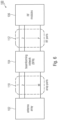
- the extension of the RTS-method is the so-called Wireless Cable approach (WLC), cf. Fig. 4 , [7] that can be applied in non-anechoic environments.
- WLC Wireless Cable approach
- the following calibration procedure for the channel matrix H C is applied.
- the DUT 12 backend has to be separated from the DUT-antennas 20.
- the calibration measurement system has to be connected via cables to measure the chamber's 24 propagation channel characteristics including the OTA antenna 22 and DUT antennas 20 characteristics.
- WFS wave field synthesis
- MIMO Multiprobe method [10,11] can be applied for device testing as well.
- a set of plane waves, defined by the targeted propagation channel characteristic are emulated. This is done by an arrangement of several OTA emulation antennas.
- the number of emulation antennas and the operation frequency dictates the maximum dimension of a DUT in which plane waves can be emulated.
- the drawback of the WFS method is the high number of needed emulation antennas.
- 24 emulation antennas at an operating frequency of 1.5GHz in a 2D antenna arrangement allow for a maximum electrical DUT size of approximately 0.7m.
- WFS is the most expensive one in terms of hardware requirements especially if the DUT is large. Furthermore, this method cannot be applied in non-anechoic environments. This method is mentioned here for completion and because it does not require a DUT calibration as the previously mentioned methods.
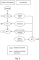
- Fig. 5 gives an overview of the existing test methods by showing the advances of each approach.
- the methods marked with a rectangle operate in non-anechoic environments; wile methods marked with a triangle can be used only in anechoic environments.
- the above described TSM (see Fig. 2 ), RTS method (see Fig. 3 ) and WLC method (see Fig. 4 ) are only suitable for DUTs that allow disconnecting the DUT' antennas from the antenna ports.
- the WFS method can be used for highly integrated devices, it is very expensive and complex one in terms of hardware requirements.
- device interfaces of highly integrated communication devices are neither available nor accessible.
- non-destructive testing or calibration of the device' components e.g., antennas, beamforming networks and down/up-converters, etc.
- US 2012/0230380 A1 discloses a method for determining a beamforming vector or a beamforming channel matrix in a communication system including a transmitting station and a receiving station, and a communication system are described.
- the transmitting and receiving stations include respective antenna groups and respective codebooks include a plurality of predefined beamforming vectors for the antenna group.
- FIG. 1 For example, the method may be used for calibrating/testing components of the multi-antenna receiver downstream (in receive direction) RF ports of the multi-antenna receiver).
- the method comprises the step of wirelessly transmitting a first signaling information between the device under test and a device tester, the first signaling information indicating a calibration request, wherein the first signaling information is transmitted by the device under test or the device tester.
- the method comprises the step of estimating, in response to the first signaling information, channel transfer function matrices between RF ports of the multi-antenna receiver of the device under test and antenna ports of the device tester using reference signals wirelessly transmitted from the device tester to the device under test, and transmitting the estimated channel transfer function matrices or an information derived therefrom from the device under test to the device tester. Further, the method comprises the step of wirelessly transmitting a second signaling information between the device under test and the device tester, the second signaling information indicating a precoded transmission request, wherein the second signaling information is transmitted by the device under test or the device tester.
- the method comprises the step of wirelessly transmitting, in response to the second signaling information, reference signals from the device tester to the device under test using precoder matrices selected or determined based on the estimated channel transfer function matrices or the information derived therefrom, to obtain interference free channels between the device tester and the device under test allowing the reference signals to be received independently at each of the RF ports of the multi-antenna receiver of the device under test.
- DUT device under test
- Fig. 6 shows a schematic block diagram of a multi-antenna transceiver (transmitter and/or receiver) of a device under test 100.
- the multi-antenna transceiver of the device under test 100 comprises an antenna array 102, a beamforming network 104 and at least one RF module 106.
- the beamforming network 104 comprises M array ports (or antenna ports) 110 and P RF ports 112, wherein M can be a natural number greater than or equal to two, M ⁇ 2, and wherein P can be a natural number greater than or equal to two, P ⁇ 2.
- the antenna array 102 or more precisely, the M antennas of the antenna array 102 can be connected to the M array ports 110 of the beamforming network 104, wherein the at least one RF module 106 can be connected to the P RF ports 112 of the beamforming network 104.
- the multi-antenna transceiver (transmitter and/or receiver) of the device under test 100 may comprise at least one transceiver module (e.g., at least one transmitter module and/or at least one receiver module), configured to perform a digital signal processing.
- the at least one transceiver module can be connected to the at least one RF module 106.
- the multi-antenna transceiver (transmitter and/or receiver) of the device under test 100 may comprise analog-to-digital converters and/or digital-to-analog converters connected between the at least one RF module 106 and the at least one (digital) transceiver module.
- the beamforming network 104 can be an analog beamforming network.
- the multi-antenna transceiver can be configured to perform a digital beamforming e.g., using the at least one transceiver module.
- the multi-antenna transceiver can comprise a hybrid beamforming network having an analog portion and a digital portion.
- the analog portion of the hybrid beamforming network can be implemented in the beamforming network 104, wherein the digital portion of the beamforming network can be implemented in the at least one transceiver module.
- the multi-antenna transceiver also can comprise only a digital beamforming network implemented in the at least one transceiver module.
- the multi-antenna transceiver comprises a hybrid beamforming network.
- the present invention is not limited to such embodiments. Rather, the below description is also applicable to analog and/or digital beamforming networks.
- the relative amplitude and phase values across the antenna elements of the array 102 define the beams of the antenna array 102.
- the beamforming network 104 can comprise M array ports (or antenna ports) 110 and P RF ports 112 that are connected to the M antenna elements 102 and the P transmit/receive (RF) modules 106 of the DUT 100, respectively (see Fig. 6 ).
- a switch block can be included in the beamforming network 104 for calibration purposes, as shown by way of example in Figs. 7a and 7b .
- Fig. 7a shows a schematic block diagram of a beamforming network 104 comprising a separate switch block 116 configured to selectively activate or deactivate each antenna port of the M antenna ports 110 of the beamforming network
- Fig. 7b shows a schematic block diagram of a beamforming network 104 having integrated switches configured to selectively activate or deactivate each antenna port of the M antenna ports 110 of the beamforming network.
- Figs. 7a and 7b show examples of beamforming networks including a switch block for calibration purpose with a control signal.
- the switches in the switch block 116 can be controllable by a control signal and can disconnect selectively the antenna ports 110 from the BFN 104 (see Fig. 7a ).
- the switch block can be directly a part of the beamforming network 104 (see Fig. 7b ).
- the switches can be responsible to connect selectively a single array port m to a single RF port p during the calibration process.
- LNAs in receive mode of the DUT 100
- PAs in transmit mode of the DUT 100
- switches off could mean, for example, a 30 dB higher isolation but depends upon the LNAs or PAs.
- each LNA or PA at an antenna element or a plurality of LNAs or PAs e.g. included in the beamforming network 104 can jointly be gated by a control signal to "on" (i.e., activated) or to "off” (i.e., non-activated or deactivated).
- an LNA/PA is gated to "on” the signal from the related antenna/BFN array port can be amplified and passed to the BFN array port ⁇ antenna.
- the above three configurations allow to remove or at least to reduce undesired coupling of array ports 110 or antenna elements during the calibration process.
- Fig. 8 shows a schematic block diagram of a calibration/testing setup for calibrating/testing components of the multi-antenna transceiver of the device under test 100.
- the device under test 100 can be placed or positioned in an echoic chamber 120, wherein a device tester (or control site) 130 can be used for performing the calibration/testing of the components of the device under test 100.
- the multi-antenna transceiver of the device under test 100 can comprise an antenna array 102, an analog beamforming network 104 and at least one RF module (not shown in Fig. 8 ).
- the analog beamforming network 104 comprises M array ports (or antenna ports) 110 and P RF ports 112.
- the antenna array 102 or more precisely, the M antennas of the antenna array 102 can be connected to the M array ports 110 of the beamforming network 104.
- the switch matrix 136 which can also be implemented directly in the beamforming network (see Fig. 6b) or be realized by controlling, for example, the LNAs or PAs accordingly, is also indicated in Fig. 8 .
- the control side 130 can comprise N antennas 132 connected to N antenna ports 134 of a precoder 136 of the control side 130.
- Tx modules transmitter
- Rx modules receiver
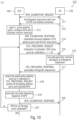
- Fig. 9 shows a flowchart of a method 200 for wirelessly calibrating a beamforming network of a multi-antenna receiver of a device under test 100, according to an embodiment.
- the method 200 may be used for calibrating/testing components (i.e., the beamforming network 104) of the multi-antenna receiver downstream (in receive direction) antenna ports 110 of the multi-antenna receiver.
- the method 200 comprises the step of wirelessly transmitting a first signaling information between the device under test 100 and a device tester 130, the first signaling information indicating a calibration request, wherein the first signaling information is transmitted by the device under test 100 or the device tester 130.
- the calibration request can be initiated by the device under test 100 itself.
- the device under test 100 may transmit the first signaling information with the calibration request to the device tester 130.
- the calibration request can be initiated by the device tester 130.
- the device tester 130 may transmit the first signaling information with the calibration request to the device under test 100 which receives the first signaling information.
- the device under test 100 may switch into a calibration mode (different from a normal operation mode) upon transmitting or receiving the first signaling information.
- the first signaling information can be a BFN_CALIBRATION_REQUEST message.
- the method 200 comprises a step 204 of estimating, in response to the first signaling information, channel transfer function matrices between active antenna ports 110 of the multi-antenna receiver of the device under test 100 and antenna ports 134 of the device tester 130 using reference signals wirelessly transmitted from the device tester 130 to the device under test 100, and transmitting the estimated channel transfer function matrices or an information derived therefrom from the device under test 100 to the device tester 130.
- the estimated channel transfer function matrices or the information derived therefrom can be transmitted to the device tester 130 using a BFN_CALIBRATION_RESPONSE message.
- the step 204 can comprise connecting each active antenna port 110 of the beamforming network 104 to exactly one RF port 112 of beamforming network for estimating the channel transfer function matrices.
- the step 204 can comprise activating a first group of antenna ports of the beamforming network 104 of the device under test 100, to obtain the active antenna ports, while deactivating the other antenna ports of the beamforming network 104.
- channel transfer function matrices describing the channels between the first group of active antenna ports and the antenna ports 134 of the device tester 130 are obtained.
- the step 204 can comprise activating a second group of antenna ports 110 of the beamforming network 104 of the device under test 100, while deactivating the other antenna ports of the beamforming network 104, and estimating channel transfer function matrices between the second group of antenna ports of the device under test and antenna ports of the device tester using reference signals wirelessly transmitted from the device tester 130 to the device under test 100, to obtain channel transfer function matrices describing channels between the second group of active antenna ports and the antenna ports 134 of the device tester 130.
- These channel transfer function matrices can also be transmitted (e.g., together with the previously estimated channel transfer function matrices) to the device tester 130.
- the method 200 comprises the step 206 of wirelessly transmitting a second signaling information between the device under test 100 and the device tester 130, the second signaling information indicating a precoded transmission request, wherein the second signaling information is transmitted by the device under test 100 or the device tester 130.
- the second signaling information can be a OTA_PRECODING_REQUEST message.
- the second signaling information may also indicate the active antenna ports of the multi-antenna receiver of the device under test, such as the first group of active antenna ports and the second group of active antenna ports.
- the method 200 comprises a step 208 of wirelessly transmitting, in response to the second signaling information, precoded reference signals from the device tester 130 to the device under test 100 using precoder matrices selected or determined based on the estimated channel transfer function matrices or the information derived therefrom, to obtain interference free channels (or orthogonal channels) between the device tester 130 and the device under test 100 allowing the reference signals to be received independently at each of the active antenna ports 110 of the multi-antenna receiver of the device under test 100.
- the device tester 130 may transmit a OTA_PRECODING_RESPONSE message indicating the following transmission of reference signals.
- the step 208 can comprise activating the first group of antenna ports of the beamforming network 104 of the device under test 100, to obtain the active antenna ports, while deactivating the other antenna ports of the beamforming network 104.
- precoded reference signals can be transmitted from the device tester 130 to the device under test 100 using precoder matrices corresponding to the first group of active antenna ports 110, such that interference free channels (or orthogonal channels) are obtained allowing the reference signals to be received independently at each port of the first group of active antenna ports 110.
- the step 208 can comprise activating the second group of antenna ports of the beamforming network 104 of the device under test 100, while deactivating the other antenna ports of the beamforming network 104.
- precoded reference signals can be transmitted from the device tester 130 to the device under test 100 using precoder matrices corresponding to the second group of active antenna ports 110, such that interference free channels (or orthogonal channels) are obtained allowing the reference signals to be received independently at each port of the second group of active antenna ports 110.
- the step 208 can comprise characterizing the frequency response of the beamforming network using the received reference signals and using specific beamforming network operating parameters (e.g., specific values for phase-shifters and/or attenuators). For example, amplitude and/or phase measurements can be performed on the RF ports over the specified channel bandwidth, to characterize the frequency response of the beamforming network.
- the device under test 100 may optionally transmit a third signaling information (e.g., a BFN_CALIBRATION_RESPONSE message) to the device tester 130.
- a third signaling information e.g., a BFN_CALIBRATION_RESPONSE message
- control site (CS) 130 may trigger the DUT 100 to calibrate its BFN 104 by sending the BFN_CALIBRATION_REQUEST (first signaling information) message to the DUT 100.
- BFN_CALIBRATION_REQUEST first signaling information
- the DUT 100 When the DUT 100 is in the E-UTRA connected state and receives such a command, it enters the calibration mode and moves to step 1. Note that the DUT 100 may also initiate the BFN 104 calibration by itself (without the indication from the CS (BFN_CALIBRATION_REQUEST message)).
- the DUT 100 may select L (L ⁇ P) active array ports 110 and switch off the remaining array ports 110 of its BFN 104.
- the algorithm for selecting the L active array ports 110 and the specific settings for the phase shifters and attenuators are left up to the DUT 100 implementation (e.g. maximum gain, no attenuation, phase 0°).
- reference signals such as the CSI-RS (BS-UE link) or SRS (UE-BS link)
- Step 1 The above procedure (Step 1) can be repeated for all groups of DUT array ports 110 that need to be calibrated.
- the DUT 100 may have full knowledge of all channels between the O CS antenna ports 134 and the M DUT array ports 110.
- the DUT 100 may generates a report (BFN_CALIBRATION_RESPONSE message) containing information about the measured MIMO channel matrices in (2), and sends them via an uplink session to the CS 130.
- a report (BFN_CALIBRATION_RESPONSE message) containing information about the measured MIMO channel matrices in (2), and sends them via an uplink session to the CS 130.
- the DUT 100 may requests a signal-precoded transmission (OTA_PRECODING_REQUEST message (second signaling information)) by the CS 130 such that the DUT may perform calibration of its BFN 104.
- OTA_PRECODING_REQUEST message second signaling information
- the DUT 100 may inform the CS 130 about the actual DUT 100 array ports 110 (OTA_PRECODING_REQUEST message) to be involved in the current DUT BFN calibration step. Note that the number of these DUT array ports 110 may have to be smaller or equal than the number of CS antenna ports 134.
- the precoder matrices can be applied at the CS 130 to the reference sequences sent over O CS antenna ports 134/ N OTA antennas 132.
- the aim of the signal precoding at the CS 130 is to create an interference-free downlink channel allowing the reference signals sent by the CS 130 to be received independently at each DUT array port 110.
- the CS 130 may inform the DUT 100 by sending an OTA_PRECODING_RESPONSE message indicating that the DUT 100 may start the calibration of its BFN 104.
- step 3 the calibration of the BFN 104 for the selected DUT 100 array ports 110 occurs in the second stage.
- the DUT 100 may select the involved array ports 110 in the calibration, switches off remaining array ports and sets specific values to the phase-shifters and attenuators of its BFN 104 with respect to a specific calibration procedure.
- the involved DUT array ports 110 are advantageously identical to the selected DUT array ports 110 from Step 2.
- the DUT 100 may perform amplitude and phase measurements on the RF ports 112 over the specified channel bandwidth to characterize the frequency response of the BFN 104. Note that the detailed steps of the calibration procedure (settings of specific phase and gain values) are left up on the DUT 100 implementation. The measurement period that is used to determine the frequency response of the BFN 104 depends also on the DUT 100 implementation.
- DUT 100 When DUT 100 has finished the measurements, it may send a BFN_CALIBRATION_RESPONSE message to the CS 130 containing information about the current calibration step. Moreover, it may send a request to the CS 130 to change the precoder matrices such that calibration of remaining DUT array ports 110 can be performed. (see Step 2).
- the CS 130 may inform the DUT on the selected active array ports and the settings for the phase shifters and attenuators during Step 1.
- the CS 130 may send a request to the DUT 100 to re-estimate the channel transfer matrices for selected antenna ports with a different setting for the phase shifters and attenuators of the DUT BFN 104 in Step 1. In this way saturation effects of the LNAs may be reduced and an improved isolation between the different transmission streams may be achieved when applying the channel inverse in (4).
- the selection of the optimal DUT 100 orientation can be included in the above procedure as well.
- the CS 130 can request to change the DUT 100 orientation (if possible and sends a control command to the DUT positioner) to improve the isolation between transmit streams and to avoid nulls in the antenna patterns.
- the CS 130 may request the DUT 100 to selectively switch off antenna ports 110 and to set specific gain and phase values to the attenuators and phase-shifters of the BFN 104, respectively, during Step 1.
- the DUT 100 may transmit the BFN_CALIBRATION_RESPONSE message with the estimated channels between O CS antenna ports 215 and M DUT array ports 110 to the CS 130.
- the CS 130 may calculate precoder matrices and apply same to orthogonal sequences.
- the CS 130 may transmit the OTA_PRECODING_RESPONSE message and the precoded orthogonal sequences to the DUT 100.
- the DUT 100 may select the same active antenna ports as indicated in the second signaling information (e.g., OTA_PRECODING_REQUEST message) and switch off the remaining antenna ports and calibrate its BFN 103.
- the BFN 100 may calculate the frequency response of its BFN 104.
- the DUT 100 may transmit the BFN_CALIBRATION_RESPONSE message to the CS 130.
- the DUT 100 may determine whether its BFN 104 is calibrated for all M array ports 110. If the BFN 104 is calibrated for all M array ports 110, then calibration/testing is finished, else steps five to eleven are repeated.
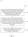
- Fig. 11 shows a flowchart of a method 230 for wirelessly calibrating/testing a beamforming network of a multi-antenna transmitter of a device under test 100, according to an embodiment.
- the method 230 may be used for calibrating/testing components (i.e., the beamforming network 104) of the multi-antenna transmitter upstream (in transmit direction) antenna ports 110 of the multi-antenna transmitter.
- the method 230 comprises a step 232 of wirelessly transmitting a first signaling information between the device under test 100 and a device tester 130, the first signaling information indicating a calibration request, wherein the first signaling information is transmitted by the device under test 100 or the device tester 130.
- the calibration request can be initiated by the device under test 100 itself.
- the device under test 100 may transmit the first signaling information with the calibration request to the device tester 130.
- the calibration request can be initiated by the device tester 130.
- the device tester 130 may transmit the first signaling information with the calibration request to the device under test 100 which receives the first signaling information.
- the device under test 100 may switch into a calibration mode (different from a normal operation mode) upon transmitting or receiving the first signaling information.
- the first signaling information can be a BFN_CALIBRATION_REQUEST message.
- the step 232 can comprise wirelessly transmitting a second signaling information (e.g., BFN_CALIBRATION_RESPONSE message) between the device under test 100 and a device tester 130, wherein the BFN_CALIBRATION_RESPONSE message transmitted by the device under test 100 or the device tester 130.
- the BFN_CALIBRATION_RESPONSE message can indicate parameters to be used in the following steps, such as a required measurement accuracy, a configuration of the beamforming network, a number of antenna ports of the device under test 100 and/or a number of antenna ports 134 of the device tester.
- the method 230 comprises a step 234 of estimating, in response to the first signaling information, channel transfer function matrices between active antenna ports 110 of the multi-antenna transmitter of the device under test and antenna ports 134 of the device tester using reference signals wirelessly transmitted from the device under test 100 to the device tester 130.
- the reference signals can be transmitted together with a BFN_CALIBRATION_START message indicating a start of the calibration from the device under test 100 to the device tester 110.
- the step 234 can comprise connecting each active antenna port 110 of the beamforming network 104 to exactly one RF port 112 of beamforming network for estimating the channel transfer function matrices.
- the step 234 can comprise activating a first group of antenna ports of the beamforming network 104 of the device under test 100, to obtain the active antenna ports, while deactivating the other antenna ports of the beamforming network 104.
- channel transfer function matrices describing the channels between the first group of active antenna ports and the antenna ports 134 of the device tester 130 are obtained.
- the step 234 can comprise activating a second group of antenna ports 110 of the beamforming network 104 of the device under test 100, while deactivating the other antenna ports of the beamforming network 104, and estimating channel transfer function matrices between the second group of antenna ports of the device under test 100 and antenna ports 134 of the device tester using reference signals wirelessly transmitted from the device under test 100 to the device tester 130, to obtain channel transfer function matrices describing channels between the second group of active antenna ports 110 and the antenna ports 134 of the device tester 130.
- the step 234 can comprise wirelessly transmitting a third signaling information from the device tester 130 to the device under test 100, the third signaling information indicating that the estimation of the channel transfer function matrices is finished.
- the third signaling information can be a BFN_CALIBRATION_FINISHED message.
- the method 230 comprises the step 236 of selecting or estimating equalizer matrices using the estimated channel transfer function matrices or the information derived therefrom.
- the step 236 can comprise wirelessly transmitting a fourth signaling information from the device under test 100 to the device tester 130, the fourth signaling information indicating a calibration data request, wherein the equalizer matrices or the information derived therefrom is transmitted from the device tester 130 to the device under test 100 in response to the fourth signaling information.
- the fourth signaling information can be a BFN_CALIBRATION_DATA_REQUEST message.
- the equalizer matrices or the information derived therefrom can be transmitted from the device tester 130 to the device under test 100 using a BFN_CALIBRATION_DATA_RESPONSE message.
- the CS 130 may send a BFN 104 calibration request message (BFN_CALIBRATION_REQUEST message (first signaling information)) to the DUT 100.
- BFN_CALIBRATION_REQUEST message first signaling information
- the message may contain information about the CS antenna port 134 configuration.
- the BFN calibration may be triggered directly by the DUT 100 by sending the BFN_CALIBRATION_REQUEST message to the CS 130. Either the DUT 100 or the CS 130 initiate the DUT calibration, the following calibration information may be signaled (using the BFN_CALIBRATION_REQUEST message and/or a BFN_CALIBRATION_RESPONSE message) between the CS 130 and DUT 100.
- the calibration information may include a required measurement accuracy that has to be fulfilled per measurement by the CS 130.
- the calibration information may include a BFN configuration (number of links between P and M, number of possible settings per link e.g. number of attenuator steps, phase shifter steps, PA gain steps).
- the calibration information may include a number of antenna ports 110,134 at DUT 100 and CS 130.
- the calibration information may include a channel bandwidth (note that it is typically the intention to measure the BFN frequency response using fully allocated channels (measurement of CSI-RS or SRS across the entire channel bandwidth)).
- the DUT 100/CS 130 may receive the BFN_CALIBRATION_RESPONSE message, wherein th DUT 100 and CS 130 can perform the following steps.
- the DUT 100 may configure the BFN 104 with specific phase and gain values. The selection of array ports and BFN settings (phase and gain values) is left up to the DUT 100 implementation.
- the DUT 100 may send reference sequences on the activated DUT array ports 110 and send a BFN_CALIBRATION_START message (containing the labeling of activated DUT array ports for the specific measurement) to the CS 130.
- the CS 130 may perform measurements on the received sequences sent from the DUT 100 and estimate the wideband channel matrix between the L activated DUT array ports 110 and the O CS antenna ports 134/N OTA antennas 132.
- the channel transfer matrix T ⁇ p q ⁇ C O ⁇ 1 , q 1, ...
- the CS 130 may send a BFN_CALIBRATION_FINISHED message to the DUT 100 signaling that the measurement for the selected setup of DUT 100 antenna ports 110 and BFN 104 setting is finished.
- the DUT when the DUT receives the BFN_CALIBRATION_FINISHED message, it optionally selects another set of active DUT array ports and BFN settings.
- steps 1 to 5 can be repeated for all DUT array ports 110 and BFN 104 settings.
- the DUT 100 may send a BFN_CALIBRATION_DATA_REQUEST message to the CS 130, indicating that the CS 130 shall provide the collected calibration date to the DUT 100.
- the equalizer matrices can be calculated based on MMSE, ZF or another objective function. Note that, the equalizer needs to be calculated for a specific BFN configuration ⁇ , ⁇ ⁇ (0, ... , S ) of RF paths, phase and gain values. This configuration can be selected by the CS 130 itself, or optionally may be signaled by the DUT 100 to the CS 130.
- the diagonal matrices G ⁇ cal s q can be calculated for all setups and DUT antenna ports 110 involved in the calibration and send in a report (BFN_CALIBRATION_DATA_RESPONSE message) to the DUT 100.
- Fig. 12 shows a flowchart of a method 240 for for a DUT BFN transmit mode calibration.
- the first signaling information e.g., BFN_CALIBRATION_REQUEST message
- the second signaling information e.g., BFN_CALIBRATION_RESPONSE message
- the DUT 100 can select active antenna ports 110, switch off remaining antenna ports and configure its BFN 104.
- the DUT can transmit a BFN_CALIBRATION_START message to the CS 130 and transmit the reference sequences (e.g., CSI-RS, SRS).
- the CS 130 can estimate channel matrices between active DUT antenna ports 110 and O CS antenna ports 134 (measurement #1).
- the CS 130 can transmit the third signaling information (BFN_CALIBRATION_FINISHED message) to the DUT 100.
- the DUT 100 can select different active antenna ports 110, switch off remaining antenna ports and configure its BFN 104.
- the DUT 100 can transmit a BFN_CALIBRATION_START message to the CS 130 and transmit the reference sequences (e.g., CSI-RS, SRS).
- the CS 130 can estimate channel matrices between the active DUT antenna ports 110 and O CS antenna ports 134 (measurement #U).
- the CS 130 can transmit the third signaling information (BFN_CALIBRATION_FINISHED message) to the DUT 100.
- the DUT 100 can transmit the fourth signaling information (BFN_CALIBRATION_DATA_REQUEST message) to the CS 130.
- the CS 130 can calculate the frequency response of the DUT BFN 104.
- the CS 130 can transmit the fifth signaling information (BFN_CALIBRATION_DATA_RESPONSE message) with the DUT BFN response to the DUT 100.
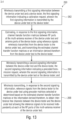
- Fig. 13 shows a flowchart of a method 260 for wirelessly calibrating/testing a receive module of a multi-antenna receiver of a device under test 100, according to an embodiment.
- the method 260 may be used for calibrating/testing components (i.e., the receive module 106) of the multi-antenna receiver downstream (in receive direction) RF ports 112 of the multi-antenna receiver.
- the method 260 comprises a step 262 of wirelessly transmitting a first signaling information between the device under test and a device tester, the first signaling information indicating a calibration request, wherein the first signaling information is transmitted by the device under test or the device tester.
- the calibration request can be initiated by the device under test 100 itself.
- the device under test 100 may transmit the first signaling information with the calibration request to the device tester 130.
- the calibration request can be initiated by the device tester 130.
- the device tester 130 may transmit the first signaling information with the calibration request to the device under test 100 which receives the first signaling information.
- the device under test 100 may switch into a calibration mode (different from a normal operation mode) upon transmitting or receiving the first signaling information.
- the first signaling information can be a DUT_RX_CHANNEL_MEASURMENT_REQUEST message.
- the method 260 comprises a step 264 of estimating, in response to the first signaling information, channel transfer function matrices between RF ports 112 of the multi-antenna receiver of the device under test 100 and antenna ports 134 of the device tester 130 using reference signals wirelessly transmitted from the device tester 130 to the device under test 100, and transmitting the estimated channel transfer function matrices or an information derived therefrom from the device under test 100 to the device tester 130.
- the estimated channel transfer function matrices or the information derived therefrom can be transmitted to the device tester 130 using a DUT_RX_CHANNEL_MEASURMENT_RESPONSE message.
- the step 264 can comprise activating a group of antenna ports of the beamforming network 104 of the device under test 100, to obtain the active antenna ports, while deactivating the other antenna ports of the beamforming network 104. Further, the step 264 can comprise connecting the active antenna ports 110 to the RF ports 112.
- the step 264 can further comprise setting specific beamforming network operating parameters, such as values for the phase shifters and attenuators of the beamforming network.
- the method 260 comprises a step 266 of wirelessly transmitting a second signaling information between the device under test 100 and the device tester 130, the second signaling information indicating a precoded transmission request, wherein the second signaling information is transmitted by the device under test 100 or the device tester 130.
- the second signaling information can be RECEIVER_SENSITIVITY_MEASUREMENT message.
- the method 260 comprises a step 268 of wirelessly transmitting, in response to the second signaling information, reference signals from the device tester to the device under test using precoder matrices selected or determined based on the estimated channel transfer function matrices or the information derived therefrom, to obtain interference free channels between the device tester and the device under test allowing the reference signals to be received independently at each of the RF ports of the multi-antenna receiver of the device under test.
- the step 268 can comprise measuring metrics specifying the performance of the device under test 100.
- the DUT 100/CS 130 may send a receiver testing request (DUT_RX_CHANNEL_MEASUREMENT_REQUEST message) to the CS 130/DUT 100.
- a receiver testing request DUT_RX_CHANNEL_MEASUREMENT_REQUEST message
- the DUT 100 can configure its BFN 104, select a number of active DUT array ports 100 and set values for the phase shifters and attenuators of its BFN 104 (it is not required that each array port ( m ) is now connected to a single RF port ( p )).
- the DUT 100 can perform measurements on the received reference sequences (e.g. CSI_RS or SRS sequences) sent by the CS 130 to estimate the channel matrices D ( q ) between the O CS antenna ports 100 and the P RF ports 112 of the DUT 100.
- the precoder matrices can be applied to the transmitted signals at the CS 130 with the aim to create an equivalent ideally interference-free rank-P downlink channel allowing the (precoded) transmitted signals from the CS 130 to be received independently at each DUT RF port 112.
- the CS 130/DUT 100 may request the measurement of certain performance metrics by the DUT 100.
- the DUT 100 has to set the BFN 104 as in the second step and the remaining components of the DUT 100 can be running as in standard operation mode.
- metrics specifying the performance of the DUT 100 can be measured, such as throughput, CQI, BLER, etc.
- the CS 130 can change the transmit power, modulation scheme or any other parameter to measure the impact on the performance of the DUT 100.
- the DUT 100 measures the P RSSIs (received signal strength indicators) and send them back to the CS 130.
- the CS 130 may reduce step-wise the transmit power after receiving P measured RSSIs from the DUT 100 corresponding to a certain transmit power (RECEIVER_SENSITIVITY_MEASUREMENT).
- Fig. 14 shows a flowchart of a method 270 for wirelessly calibrating/testing a transmit module of a multi-antenna transmitter of a device under test 100, according to an embodiment.
- the method 270 may be used for calibrating/testing components (i.e., the transmit module 106) of the multi-antenna transmitter upstream (in transmit direction) RF ports 112 of the multi-antenna receiver.
- the method 270 comprises a step 272 of wirelessly transmitting a first signaling information between the device under test 100 and a device tester 130, the first signaling information indicating a calibration request, wherein the first signaling information is transmitted by the device under test 100 or the device tester 130.
- the calibration request can be initiated by the device under test 100 itself.
- the device under test 100 may transmit the first signaling information with the calibration request to the device tester 130.
- the calibration request can be initiated by the device tester 130.
- the device tester 130 may transmit the first signaling information with the calibration request to the device under test 100 which receives the first signaling information.
- the device under test 100 may switch into a calibration mode (different from a normal operation mode) upon transmitting or receiving the first signaling information.
- the first signaling information can be a DUT_TX_CHANNEL_MEASUREMENT_REQUEST message.
- the method 270 comprises a step 274 of estimating, in response to the first signaling information, channel transfer function matrices between RF ports 112 of the multi-antenna transmitter of the device under test 100 and antenna ports 134 of the device tester 130 using reference signals wirelessly transmitted from the device under test 100 to the device tester 130.
- the estimated channel transfer function matrices or the information derived therefrom can be transmitted to the device tester 130 using a second signaling information (DUT_RX_CHANNEL_MEASURMENT_RESPONSE message).
- the step 274 can comprise activating a group of antenna ports of the beamforming network 104 of the device under test 100, to obtain the active antenna ports, while deactivating the other antenna ports of the beamforming network 104. Further, the step 274 can comprise connecting the active antenna ports 110 to the RF ports 112.
- the step 274 can further comprise setting specific beamforming network operating parameters, such as values for the phase shifters and attenuators of the beamforming network.
- the method 270 comprises a step 272 of selecting or estimating equalizer matrices using the estimated channel transfer function matrices or the information derived therefrom.
- the method 270 can further comprise measuring metrics specifying the transmit performance of the device under test (e.g., throughput, CQI, BLER) using the selected or estimated equalizer matrices.
- metrics specifying the transmit performance of the device under test e.g., throughput, CQI, BLER
- the DUT 100/CS 130 may send a transmitter testing request (DUT_TX_CHANNEL_MEASUREMENT_REQUEST message) to the CS/DUT.
- a transmitter testing request DUT_TX_CHANNEL_MEASUREMENT_REQUEST message
- the DUT 100 can configure its BFN 104 and select the active DUT array ports (it is not required that an array port ( m ) is exactly connected to only one RF port (p)).
- the DUT 100 can send reference sequences on its P RF ports 112.
- the CS 130 can performs measurements on the received sequences sent from the DUT 100 and estimates the wideband channel matrix U ( q ) between the P RF ports 112 and the O CS antenna ports 134/N OTA antenna ports.
- the CS 130 can send a DUT_RX_CHANNEL_MEASUREMENT_RESPONSE message to the DUT 100 signaling that the measurements are finished.
- the DUT 100/CS 130 may then request the measurement of certain performance metrics by the CS 130.
- the DUT 100 has to set the BFN 104 as in step 2 and the remaining components of the DUT 100 can run as in standard operation mode.
- metrics specifying the performance of the DUT 100 can be measured at the CS 130, such as throughput, CQI, BLER, etc.
- the CS 130 may request to change the Tx power of the DUT 100, modulation scheme or any other parameter to measure the impact on the performance of the DUT 100.
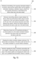
- Fig. 15 shows a flowchart of a method 280 for wirelessly calibrating/testing antennas 110 of a multi-antenna transceiver of a device under test 100, according to an embodiment.
- the method 280 may be used for calibrating/testing components (i.e., the antennas) of the multi-antenna transceiver downstream (in transmit direction) or upstream (in receive direction) the antenna ports of the multi-antenna receiver.
- the method 280 comprises a step 282 of wirelessly transmitting a first signaling information between the device under test 100 and a device tester 130, the first signaling information indicating a calibration request, wherein the first signaling information is transmitted by the device under test 100 or the device tester 130.
- the calibration request can be initiated by the device under test 100 itself.
- the device under test 100 may transmit the first signaling information with the calibration request to the device tester 130.
- the calibration request can be initiated by the device tester 130.
- the device tester 130 may transmit the first signaling information with the calibration request to the device under test 100 which receives the first signaling information.
- the device under test 100 may switch into a calibration mode (different from a normal operation mode) upon transmitting or receiving the first signaling information.
- the method 282 comprises a step of wirelessly transmitting reference signals between the device under test 100 and the device tester 130 using one (e.g., exactly one) active antenna port 110 of the multi-antenna transceiver or using one RF port 112 of the multi-antenna transceiver and a fixed beamforming network, wherein the reference signals are transmitted by the device under test 100 or the device tester 130.
- one e.g., exactly one
- the method 280 comprises a step 286 of measuring at least one out of amplitude and phase of a antenna pattern for a first relative orientation between antennas of the device tester and antennas of the device under test.
- the step 286 can comprise measuring the amplitude and phase of the full polarimetric antenna pattern for a first orientation.
- the method 280 comprises a step 288 of changing the relative orientation between antennas 102 of the device under test 100 and antennas 132 of the device tester 130 to a second relative orientation.
- the method 280 comprises a step 289 of iteratively repeating the steps of wirelessly transmitting reference signals, measuring at least one out of amplitude and phase of the antenna pattern (e.g., the amplitude and phase of the full polarimetric antenna pattern) and changing the relative orientation until a predetermined termination criterion is reached.
- the antenna pattern e.g., the amplitude and phase of the full polarimetric antenna pattern
- the method 280 can further comprise wirelessly transmitting a second signaling information from the device under test 100 to the device tester 130, the second signaling information indicating a number of antenna ports 110 or RF ports 112 to be measured.
- the method 280 can further comprise wirelessly transmitting a third signaling information from the device tester 130 to the device under test 100, the third signaling information indicating a measured antenna pattern.
- the BFN is fixed to one active antenna port 110 or one active RF port 112 with a fixed BFN (e.g. Buttler matrix).
- BFN e.g. Buttler matrix
- an antenna port calibration request (resolution in angle or number of steps l ) can be initiated by the DUT 100 or CS 130.
- the DUT 100 can feed back a number of M or P ports to be measured.
- the CS 130/DUT 100 can start sending wideband reference sequences (e.g. CSI-RS, SRS).
- wideband reference sequences e.g. CSI-RS, SRS.
- the DUT 100 can send back the measured response of i-th step.
- the third and fourth steps can be repeated after a positioner is set from CS 130 to a new angle and polarization.
- the CS 130 can feedback the complete antenna pattern as pattern or EADF.
- Fig. 16 shows a flowchart of a method 290 for wirelessly calibrating/testing the digital portion of a device under test 100, according to an embodiment.
- the method 290 comprises a step 291 of wirelessly transmitting a first signaling information between the device under test 100 and a device tester 130, the first signaling information indicating a calibration request, wherein the first signaling information is transmitted by the device under test 100 or the device tester 130.
- the calibration request can be initiated by the device under test 100 itself.
- the device under test 100 may transmit the first signaling information with the calibration request to the device tester 130.
- the calibration request can be initiated by the device tester 130.
- the device tester 130 may transmit the first signaling information with the calibration request to the device under test 100 which receives the first signaling information.
- the device under test 100 may switch into a calibration mode (different from a normal operation mode) upon transmitting or receiving the first signaling information.
- the first signaling information can be a DUT_CALIBRATION_REQUEST message.
- the method 290 comprises a step 292 of estimating, in response to the first signaling information, channel transfer function matrices between active antenna ports ⁇ RF ports 110 ⁇ 112 of the multi-antenna transceiver of the device under test 100 and antenna ports 134 of the device tester using reference signals wirelessly transmitted from the device tester to the device under test.
- the step 292 can comprise activating a group of antenna ports of the beamforming network 104 of the device under test 100 to obtain active antenna ports ⁇ RF ports, while deactivating the other antenna ports 110 of the beamforming network 104.
- the step 292 can comprise setting specific beamforming network operating parameters to the analog portion of the hybrid beamforming network.
- the specific beamforming network operating parameters can be, for example, values for the phase shifters and attenuators of the beamforming network.
- the step 292 can comprise wirelessly transmitting the estimated channel transfer function matrices or an information derived therefrom form the device under test 100 to the device tester 130.
- the estimated channel transfer function matrices or the information derived therefrom can be transmitted from the device under test 100 to the device tester 130 using a DUT_CALIBRATION_RESPONSE message.
- the method 290 comprises a step 293 of wirelessly transmitting a second signaling information between the device under test and the device tester, the second signaling information indicating a precoded transmission request, wherein the second signaling information is transmitted by the device under test or the device tester.
- the method 290 comprises a step 294 of wirelessly transmitting, in response to the second signaling information, reference signals from the device tester to the device under test using precoder matrices selected or determined based on the estimated channel transfer function matrices or the information derived therefrom, to obtain interference free channels between the device tester and the device under test allowing the reference signals to be received independently at each RF port of the multi-antenna receiver of the device under test.
- the method can comprise setting the analog portion of the hybrid beamforming network to specific beamforming network operating parameters and maintaining the operating parameters of the analog beamforming network 104 fixed during calibrating/testing of the digital portion of a multi antenna transceiver.
- the method can comprise wirelessly transmitting a third signaling information from the device under test to the device tester, the third signaling information indicating the specific analog beamforming network operating parameters.
- the method can comprise that the DUT freely can change beamforming network operating parameters of the digital portion of the hybrid beamforming network during calibrating/testing of the digital portion of a multiantenna transceiver.
- the method can comprise wirelessly transmitting a fourth signaling information from the device under test to the device tester, the fourth signaling information indicating the current and/or operational beamforming network operating parameters of the analog portion of the beamforming network 104.
- the method can comprise measuring performance metrics specifying the performance of the digital portion of a multi-antenna tranceiver or of the RF module.
- the transmit parameters of signals wirelessly transmitted from the device tester to the device under test can be varied, in order to measure the performance metrics specifying the performance of the digital portion of a multiantenna receiver or of the RF module.
- the DUT 100/CS 130 sends a receiver testing request (DUT_CALIBRATION_REQUEST message) to the CS 130/DUT 100.
- the request may also include a predefined setting for the DUT BFN.
- the DUT 100 can configure its BFN 104 and select a number of active DUT array ports 110 and sets values for the phase shifters and attenuators of its BFN 104 to a predefined set (which may be signaled from the CS 130).
- the DUT 100 can perform measurements on the received reference signals (e.g. CSI_RS or SRS sequences) to estimate the channel matrices D ( q ) between the O CS antenna ports 134/ N OTA antennas 132 and the P RF ports 112 of the DUT 100.
- the received reference signals e.g. CSI_RS or SRS sequences
- the precoder matrices can be applied to the transmitted signals at the CS 130 with the aim to create an equivalent ideally interference-free rank-P downlink ⁇ uplink channel allowing the (precoded) transmitted signals from the CS to be received independently at each RF port 112.
- the CS 130/DUT 100 send/initialize the measurement (DUT_PERFTEST_REQUEST) of certain performance metrics e.g. Throughput.
- the DUT 100 may send back at time t also the decision on the chosen BFN 104 setting to the CS 130, while keeping actually the analog part of the BFN 104 as in step 2.
- the P resulting antenna patterns could be calculated or taken from a database at the CS side to embed them in the propagation channel (matrix H T ).
- H T can be adaptively changed based on the decision of the DUT 100 w.r.t. the BFN 104.
- the CS 130 can now vary for example transmit parameters such as power, modulation, channel characteristics and so on. If the settings of the analog BFN of the DUT can not be fixed during the operational mode the feedback analog BFN settings from the DUT 100 may also be applied at the CS 130 to modify P ( q ).
- the DUT BFN test (digital part) in the non-anechoic chamber allows testing the (entire) receiver in a real environment.
- the real environment can be generated using a realistic propagation channel (e.g. 3GPP Channel model, etc.).
- the channel can consider the beams formed using the BFN 104. This can be included calculatively using a feedback information from the DUT 100 indicating the settings it would (normally) apply to the BFN 104.
- the DUT 100 must maintain the BFN 104 (analog portion of the hybrid beamforming network) fixed, in order to maintain the wireless cable connection to the P RF ports 112.
- the digital beamforming actually takes place in the DUT 100 after (downstream) the RF ports 112.
- the DUT BFN test in the non-anechoic chamber allows testing the DUT under operational conditions, e.g., w.r.t. throughput in a real channel.
- the BFN 104 analog beamforming network
- the DUT 100 or a software running on the DUT and controlling the DUT
- these changes ⁇ the settings of the analog BFN that would be applied can be feedback to the CS, which may include the resulting beams in the channel.
- Fig. 16 shows a flowchart of a method 295 for wirelessly calibrating/testing a digital transmitter module of a multi-antenna transmitter of a device under test.
- the method 295 comprises a step 296 of wirelessly transmitting a first signaling information between the device under test and a device tester, the first signaling information indicating a calibration request, wherein the first signaling information is transmitted by the device under test or the device tester.
- the method 295 further comprises a step 297 of estimating, in response to the first signaling information, channel transfer function matrices between active antenna ports or RF ports of the multi-antenna transmitter of the device under test and antenna ports of the device tester using reference signals wirelessly transmitted from the device under test to the device tester.
- the method 295 further comprises a step 298 of selecting or estimating equalizer matrices using the estimated channel transfer function matrices or the information derived therefrom.
- an analog beamforming network of the multi-antenna transmitter is set to specific beamforming network parameters and maintained fixed at the set specific beamforming network parameters, during calibrating/testing the digital transmitter module of the multi-antenna receiver, even if the propagation channel between the device under test and the device tester changes to emulate multipath propagation channel.
- a third signaling information can be wirelessly transmitting from the device under test to the device tester, the third signaling information indicating specific beamforming network operating parameters the device under test would apply in a normal operation mode to the analog beamforming network responsive to the emulated multipath propagation channel in order to adapt the analog beamforming network in the normal operation mode to the multipath propagation channel.
- Wireless communication devices equipped with multiple antennas have to be calibrated and tested with respect to overall performance and conformance. These devices are typically highly integrated such that device interfaces are neither available nor accessible.
- Embodiments described herein provide a non-destructive testing and calibration approach for integrated DUTs equipped with analog, digital and hybrid beamforming networks in arbitrary laboratory environments. Feedback schemes for the new testing and calibration approach are also provided.
- Various elements and features of the present invention may be implemented in hardware using analog and/or digital circuits, in software, through the execution of instructions by one or more general purpose or special-purpose processors, or as a combination of hardware and software.
- embodiments of the present invention may be implemented in the environment of a computer system or another processing system.
- Fig. 18 illustrates an example of a computer system 400.
- the units or modules as well as the steps of the methods performed by these units may execute on one or more computer systems 400.
- the computer system 400 includes one or more processors 402, like a special purpose or a general purpose digital signal processor.
- the processor 402 is connected to a communication infrastructure 404, like a bus or a network.
- the computer system 400 includes a main memory 406, e.g., a random access memory (RAM), and a secondary memory 408, e.g., a hard disk drive and/or a removable storage drive.
- the secondary memory 408 may allow computer programs or other instructions to be loaded into the computer system 400.
- the computer system 400 may further include a communications interface 410 to allow software and data to be transferred between computer system 400 and external devices.
- the communication may be in the form electronic, electromagnetic, optical, or other signals capable of being handled by a communications interface.
- the communication may use a wire or a cable, fiber optics, a phone line, a cellular phone link, an RF link and other communications channels 412.
- computer program medium and “computer readable medium” are used to generally refer to tangible storage media such as removable storage units or a hard disk installed in a hard disk drive. These computer program products are means for providing software to the computer system 400.
- the computer programs also referred to as computer control logic, are stored in main memory 406 and/or secondary memory 408. Computer programs may also be received via the communications interface 410.
- the computer program when executed, enable the computer system 400 to implement the present invention.
- the computer program when executed, enable processor 402 to implement the processes of the present invention, such as any of the methods described herein. Accordingly, such a computer program may represent a controller of the computer system 400.
- the software may be stored in a computer program product and loaded into computer system 400 using a removable storage drive, an interface, like communications interface 410.
- the implementation in hardware or in software may be performed using a digital storage medium, for example cloud storage, a floppy disk, a DVD, a Blue-Ray, a CD, a ROM, a PROM, an EPROM, an EEPROM or a FLASH memory, having electronically readable control signals stored thereon, which cooperate (or are capable of cooperating) with a programmable computer system such that the respective method is performed. Therefore, the digital storage medium may be computer readable.
- a digital storage medium for example cloud storage, a floppy disk, a DVD, a Blue-Ray, a CD, a ROM, a PROM, an EPROM, an EEPROM or a FLASH memory, having electronically readable control signals stored thereon, which cooperate (or are capable of cooperating) with a programmable computer system such that the respective method is performed. Therefore, the digital storage medium may be computer readable.
- Some embodiments according to the invention comprise a data carrier having electronically readable control signals, which are capable of cooperating with a programmable computer system, such that one of the methods described herein is performed.
- embodiments of the present invention may be implemented as a computer program product with a program code, the program code being operative for performing one of the methods when the computer program product runs on a computer.
- the program code may for example be stored on a machine readable carrier.
- inventions comprise the computer program for performing one of the methods described herein, stored on a machine readable carrier.
- an embodiment of the inventive method is, therefore, a computer program having a program code for performing one of the methods described herein, when the computer program runs on a computer.
- a further embodiment of the inventive methods is, therefore, a data carrier (or a digital storage medium, or a computer-readable medium) comprising, recorded thereon, the computer program for performing one of the methods described herein.
- a further embodiment of the inventive method is, therefore, a data stream or a sequence of signals representing the computer program for performing one of the methods described herein. The data stream or the sequence of signals may for example be configured to be transferred via a data communication connection, for example via the Internet.
- a further embodiment comprises a processing means, for example a computer, or a programmable logic device, configured to or adapted to perform one of the methods described herein.
- a further embodiment comprises a computer having installed thereon the computer program for performing one of the methods described herein.
- a programmable logic device for example a field programmable gate array
- a field programmable gate array may cooperate with a microprocessor in order to perform one of the methods described herein.
- the methods are preferably performed by any hardware apparatus.
Landscapes
- Physics & Mathematics (AREA)
- Engineering & Computer Science (AREA)
- Computer Networks & Wireless Communication (AREA)
- Signal Processing (AREA)
- Electromagnetism (AREA)
- General Physics & Mathematics (AREA)
- Mobile Radio Communication Systems (AREA)
Description
- Embodiments relate to a method for wirelessly calibrating a multi-antenna transceiver of a device under test, and in detail, to a method for wirelessly calibrating a beamforming network and/or a transceiver module (Rx module and/or Tx module) of the device under test. Some embodiments relate to calibration and testing of hybrid analog/digital beamforming-based multi-antenna devices in anechoic and non-anechoic environments.
- Wireless communication devices equipped with multiple antennas have to be calibrated and tested with respect to overall performance and conformance.
- A well-known method for device testing is the so-called conducted test (CT) where the device' antennas are disconnected from the device under test (DUT) and a device tester is directly connected to the DUT. In such a conducted test, no wireless transmission is performed between the DUT and the device tester. This test setup in its simple manner does not consider the DUT' antenna radiation patterns during the device testing. A major drawback of the conducted test is that any kind of beamforming/beam-processing algorithms implemented in the DUT cannot be evaluated, as all signals "virtually" impinge at the same direction. Moreover, no direction- or frequency-dependent signal amplification or attenuation may be noticeable as the DUT' antennas are not present in this test.
- An extension of the conducted test is the so called two-stage method (TSM) [1], see
Figs. 1a, 1b and2 . In detail,Fig. 1a and 1b show schematic views of antenna measurement principles for small devices and for large devices, respectively.Fig. 2 shows a schematic view of a calibration/test setup 10 for the TSM. In this setup, the DUT' 12 antenna radiation patterns are measured at a first stage (Fig. 1a and 1b ) in an antenna measurement chamber where the DUT' antennas are rotated 16 such that a desired azimuth and elevation angle range is covered. When the size of theDUT 12 is too large to be rotated in all desired angular directions, it can be put onto a turntable to cover the azimuth angles by rotating theDUT 12; the elevation angles are covered by movement of the transmitter antenna or by switching the active antenna on an antenna arc, cf.Fig. 1 . At the second stage of the TSM, a conducted test between the device tester (e.g. eNodeB) and theDUT 12 is performed (seeFig. 2 ). In contrast to the simple CT setup described above, the DUT' antenna radiation patterns and the MIMO propagation channel are contained in the digital baseband signals. - In the TSM channel emulators emulate a time-variant MIMO propagation channel between the device tester/control site (CS) 18, and the
DUT 12. When the communication link between the CS and DUT is successfully established, different performance metrics of the communication link are measured and analyzed, such as data throughput, received signal strength, etc. A major disadvantage of the conducted testing, however, is that self-interference effects caused by antenna coupling of the DUT antennas cannot be considered during the test. Furthermore, typical in-band interferences caused either by signals radiated from other devices in the close vicinity of the DUT, or from non-conformant radio devices cannot be evaluated during the test. - The radiated two-stage method (RTS) [2-5], cf.,
Fig. 3 performs the TSM over-the air (OTA) in an anechoic chamber. Both self- and in-band-interference effects can be evaluated by this approach. Similar to the TSM, the DUT antenna radiation patterns are measured before device testing. For the RTS approach, theCS 18 radiates or receives phase coherent signals via O CSantenna ports 21/NOTA antennas 22, while theDUT 12 which is equipped withM antenna ports 19, receives or radiates the signals. In a first step, the chamber's 24 propagation channel characteristic is measured and stored in a channel matrix
DUT 12. Based on the measured channel matrix H C, a precoder matrix is computed and applied to the transmit signals at the CS to realize orthogonal channels and to remove the influence of the chamber's propagation characteristic between the O CS-antenna ports 21/N OTA antennas 22 and the MDUT antenna ports 19. There exists a variety of approaches for signal precoding. As an example, the precoder matrix can be calculated by the Moore-Penrose pseudo-inverse of the channel transfer matrix H C. Furthermore, a realistic MIMO propagation channel matrix H T that contains the measured DUT antenna radiation pattern(s) can be incorporated in the transmit signal at the CS. Device testing is then performed by establishing a communication link between the CS and DUT and evaluating the performance. - The extension of the RTS-method is the so-called Wireless Cable approach (WLC), cf.
Fig. 4 , [7] that can be applied in non-anechoic environments. - WLC description: The received signal at the DUT 12 (downlink case) is given as

DUT 12antenna ports 19 at frequency-bin q (q=1,...,Q), x(q) is the frequency-dependent radiated signal at theCS 22, and P (q) is the frequency-dependent precoding matrix. To measure the channel matrices H C(f) between theantenna ports 19 of theDUT 12 and theCS ports 21, reference signals are transmitted and the precoding matrices P(q), q = 1, ..., Q are set to identity matrices. Then, by pseudo-inversion of the channel matrix H C and multiplication with a desired propagation channel matrix H T, the precoder matrix can be calculated as
- Note that for simplicity, the frequency dependent notation has been omitted.
- For the RTS (narrow band) and the WLC (wide band) method the following calibration procedure for the channel matrix H C is applied. To measure the influence of the
N OTA antennas 22 at the CS-side 18, theDUT antennas 20 and the propagation channel of thechamber 24, theDUT 12 backend has to be separated from the DUT-antennas 20. At the DUT-antenna ports 19, the calibration measurement system has to be connected via cables to measure the chamber's 24 propagation channel characteristics including theOTA antenna 22 andDUT antennas 20 characteristics. - For small-sized DUTs, wave field synthesis (WFS) or the MIMO Multiprobe method [10,11] can be applied for device testing as well. Hereby, a set of plane waves, defined by the targeted propagation channel characteristic are emulated. This is done by an arrangement of several OTA emulation antennas. The number of emulation antennas and the operation frequency dictates the maximum dimension of a DUT in which plane waves can be emulated. The drawback of the WFS method is the high number of needed emulation antennas. As an example, 24 emulation antennas at an operating frequency of 1.5GHz in a 2D antenna arrangement allow for a maximum electrical DUT size of approximately 0.7m. Additionally, all signal paths that feed the emulation antennas have to be phase coherent for WFS. Compared to the other mentioned methods, WFS is the most expensive one in terms of hardware requirements especially if the DUT is large. Furthermore, this method cannot be applied in non-anechoic environments. This method is mentioned here for completion and because it does not require a DUT calibration as the previously mentioned methods.
-
Fig. 5 gives an overview of the existing test methods by showing the advances of each approach. The methods marked with a rectangle operate in non-anechoic environments; wile methods marked with a triangle can be used only in anechoic environments. As shown inFig. 5 , the above described TSM (seeFig. 2 ), RTS method (seeFig. 3 ) and WLC method (seeFig. 4 ) are only suitable for DUTs that allow disconnecting the DUT' antennas from the antenna ports. Although the WFS method can be used for highly integrated devices, it is very expensive and complex one in terms of hardware requirements. - To summarize, device interfaces of highly integrated communication devices are neither available nor accessible. As a consequence, non-destructive testing or calibration of the device' components (e.g., antennas, beamforming networks and down/up-converters, etc.) become impossible or very difficult.
-
US 2012/0230380 A1 discloses a method for determining a beamforming vector or a beamforming channel matrix in a communication system including a transmitting station and a receiving station, and a communication system are described. The transmitting and receiving stations include respective antenna groups and respective codebooks include a plurality of predefined beamforming vectors for the antenna group. - Therefore, it is the object of the present invention to provide an efficient method for non-destructively testing/calibrating highly integrated communication devices.
- This object is solved by the independent claims.
- Advantageous implementations are addressed in the dependent claims.
- Further embodiments provide a method for wirelessly calibrating/testing a receive module of a multi-antenna receiver of a device under test (for example, the method may be used for calibrating/testing components of the multi-antenna receiver downstream (in receive direction) RF ports of the multi-antenna receiver). The method comprises the step of wirelessly transmitting a first signaling information between the device under test and a device tester, the first signaling information indicating a calibration request, wherein the first signaling information is transmitted by the device under test or the device tester. Further, the method comprises the step of estimating, in response to the first signaling information, channel transfer function matrices between RF ports of the multi-antenna receiver of the device under test and antenna ports of the device tester using reference signals wirelessly transmitted from the device tester to the device under test, and transmitting the estimated channel transfer function matrices or an information derived therefrom from the device under test to the device tester. Further, the method comprises the step of wirelessly transmitting a second signaling information between the device under test and the device tester, the second signaling information indicating a precoded transmission request, wherein the second signaling information is transmitted by the device under test or the device tester. Further, the method comprises the step of wirelessly transmitting, in response to the second signaling information, reference signals from the device tester to the device under test using precoder matrices selected or determined based on the estimated channel transfer function matrices or the information derived therefrom, to obtain interference free channels between the device tester and the device under test allowing the reference signals to be received independently at each of the RF ports of the multi-antenna receiver of the device under test.
- Embodiments of the present invention are described herein making reference to the appended drawings.
- Fig. 1a
- shows a schematic view of an antenna measurement principle for small devices;
- Fig. 1b
- shows a schematic view of an antenna measurement principle for large devices;
- Fig. 2
- shows a sematic view of a calibration/test setup for the two-stage method;
- Fig. 3
- shows a schematic view of a calibration/test setup for the radiated two-stage method in an anechoic chamber;
- Fig. 4
- shows a schematic view of a calibration/test setup for the wireless cable method in a non-anechoic chamber;
- Fig. 5
- shows in a diagram an overview of the existing test methods by presenting the advances of each;
- Fig. 6
- shows a schematic block diagram of a multi-antenna transceiver of a device under test, according to an embodiment;
- Fig. 7a
- shows a schematic block diagram of a beamforming network comprising a separate switch block configured to selectively activate or deactivate each antenna port of the M antenna ports of the beamforming network, according to an embodiment;
- Fig. 7b
- shows a schematic block diagram of a beamforming network having integrated switches configured to selectively activate or deactivate each antenna port of the M antenna ports of the beamforming network, according to an embodiment;
- Fig. 8
- shows a schematic block diagram of a calibration/testing setup for calibrating/testing components of the multi-antenna transceiver of the device under test, according to an embodiment;
- Fig. 9
- shows a flowchart of a method for wirelessly calibrating a beamforming network of a multi-antenna receiver of a device under test, according to an embodiment;
- Fig. 10
- shows a flowchart of a method for a DUT BFN receive mode calibration, according to an embodiment;
- Fig. 11
- shows a flowchart of a method for wirelessly calibrating/testing a beamforming network of a multi-antenna transmitter of a device under test, according to an embodiment;
- Fig. 12
- shows a flowchart of a method for a DUT BFN transmit mode calibration, according to an embodiment;
- Fig. 13
- shows a flowchart of a method for wirelessly calibrating/testing a receive module of a multi-antenna receiver of a device under test, according to an embodiment;
- Fig. 14
- shows a flowchart of a method for wirelessly calibrating/testing a transmit module of a multi-antenna transmitter of a device under test, according to an embodiment;
- Fig. 15
- shows a flowchart of a method for wirelessly calibrating/testing antennas of a multi-antenna transceiver of a device under test, according to an embodiment;
- Fig. 16
- shows a flowchart of a method for wirelessly calibrating/testing a digital receiver module of a multi-antenna receiver of a device under test, according to an embodiment;
- Fig. 17
- shows a flowchart of a method for wirelessly calibrating/testing a digital transmitter module of a multi-antenna transmitter of a device under test, according to an embodiment; and
- Fig. 18
- illustrates an example of a computer system on which units or modules as well as the steps of the methods described in accordance with the inventive approach may execute.
- Equal or equivalent elements or elements with equal or equivalent functionality are denoted in the following description by equal or equivalent reference numerals.
- In the following description, a plurality of details is set forth to provide a more thorough explanation of embodiments of the present invention. However, it will be apparent to one skilled in the art that embodiments of the present invention may be practiced without these specific details. In other instances, well-known structures and devices are shown in block diagrams form rather than in detail in order to avoid obscuring embodiments of the present invention. In addition, features of the different embodiments described hereinafter may be combined with each other, unless specifically noted otherwise.
- Before embodiments of methods for calibrating/testing RF components (e.g., antennas, antenna ports, RF ports, beamforming networks, Tx modules (Tx = transmitter) or Rx modules (Rx = receiver)) of a wireless communication device, referred herein as to device under test (DUT) 100, are described in further detail, the device itself is described making reference to
Figs. 6 ,7a and 7b and the calibration/test setup is described making reference toFig. 8 . -
Fig. 6 shows a schematic block diagram of a multi-antenna transceiver (transmitter and/or receiver) of a device undertest 100. The multi-antenna transceiver of the device undertest 100 comprises anantenna array 102, abeamforming network 104 and at least oneRF module 106. Thebeamforming network 104 comprises M array ports (or antenna ports) 110 andP RF ports 112, wherein M can be a natural number greater than or equal to two, M ≥ 2, and wherein P can be a natural number greater than or equal to two, P ≥ 2. Theantenna array 102, or more precisely, the M antennas of theantenna array 102 can be connected to theM array ports 110 of thebeamforming network 104, wherein the at least oneRF module 106 can be connected to theP RF ports 112 of thebeamforming network 104. Further, the multi-antenna transceiver (transmitter and/or receiver) of the device undertest 100 may comprise at least one transceiver module (e.g., at least one transmitter module and/or at least one receiver module), configured to perform a digital signal processing. The at least one transceiver module can be connected to the at least oneRF module 106. Further, the Further, the multi-antenna transceiver (transmitter and/or receiver) of the device undertest 100 may comprise analog-to-digital converters and/or digital-to-analog converters connected between the at least oneRF module 106 and the at least one (digital) transceiver module. - In embodiments, the
beamforming network 104 can be an analog beamforming network. - Further, in embodiments, the multi-antenna transceiver can be configured to perform a digital beamforming e.g., using the at least one transceiver module. In other words, the multi-antenna transceiver can comprise a hybrid beamforming network having an analog portion and a digital portion. Thereby, the analog portion of the hybrid beamforming network can be implemented in the
beamforming network 104, wherein the digital portion of the beamforming network can be implemented in the at least one transceiver module. - Further, in embodiments, the multi-antenna transceiver also can comprise only a digital beamforming network implemented in the at least one transceiver module. In that case, the
M antenna ports 110 may be connected directly to theP RF ports 112, such that each antenna port is connected to exactly one RF port, i.e. M=P. - In the below description of embodiments, it is exemplarily assumed that the multi-antenna transceiver comprises a hybrid beamforming network. However, the present invention is not limited to such embodiments. Rather, the below description is also applicable to analog and/or digital beamforming networks.
- In embodiments, the relative amplitude and phase values across the antenna elements of the
array 102 define the beams of theantenna array 102. These relative phase and amplitude values are generated by the beamforming network (e.g.,analog beamforming network 104 and/or digital beamforming network implemented in the at least one RF module 106) that may comprise, for example, a plurality of phase shifters, controllable attenuators\PAs in Tx (PA = power amplifier) \LNAs in Rx (LNA = low noise amplifier), delay lines, etc., that are connected to the antenna elements of thearray 102. Thebeamforming network 104 can comprise M array ports (or antenna ports) 110 andP RF ports 112 that are connected to theM antenna elements 102 and the P transmit/receive (RF)modules 106 of theDUT 100, respectively (seeFig. 6 ). - In embodiments, a switch block can be included in the
beamforming network 104 for calibration purposes, as shown by way of example inFigs. 7a and 7b . In detail,Fig. 7a shows a schematic block diagram of abeamforming network 104 comprising aseparate switch block 116 configured to selectively activate or deactivate each antenna port of theM antenna ports 110 of the beamforming network, whereinFig. 7b shows a schematic block diagram of abeamforming network 104 having integrated switches configured to selectively activate or deactivate each antenna port of theM antenna ports 110 of the beamforming network. In other words,Figs. 7a and 7b show examples of beamforming networks including a switch block for calibration purpose with a control signal. The switches in theswitch block 116 can be controllable by a control signal and can disconnect selectively theantenna ports 110 from the BFN 104 (seeFig. 7a ). Alternatively, the switch block can be directly a part of the beamforming network 104 (seeFig. 7b ). The switches can be responsible to connect selectively a single array port m to a single RF port p during the calibration process. - Alternatively, instead of a switch block, LNAs (in receive mode of the DUT 100) or PAs (in transmit mode of the DUT 100) at the selected antenna elements can directly be switched off to increase the isolation between different antenna elements (switched off could mean, for example, a 30 dB higher isolation but depends upon the LNAs or PAs). In such a case, each LNA or PA at an antenna element or a plurality of LNAs or PAs (e.g. included in the beamforming network 104) can jointly be gated by a control signal to "on" (i.e., activated) or to "off" (i.e., non-activated or deactivated). In the case that an LNA/PA is gated to "on" the signal from the related antenna/BFN array port can be amplified and passed to the BFN array port\antenna.
- The above three configurations allow to remove or at least to reduce undesired coupling of
array ports 110 or antenna elements during the calibration process. -
Fig. 8 shows a schematic block diagram of a calibration/testing setup for calibrating/testing components of the multi-antenna transceiver of the device undertest 100. As shown inFig. 8 , the device undertest 100 can be placed or positioned in anechoic chamber 120, wherein a device tester (or control site) 130 can be used for performing the calibration/testing of the components of the device undertest 100. - As already mentioned with respect to
Fig. 6 , the multi-antenna transceiver of the device undertest 100 can comprise anantenna array 102, ananalog beamforming network 104 and at least one RF module (not shown inFig. 8 ). Theanalog beamforming network 104 comprises M array ports (or antenna ports) 110 andP RF ports 112. Theantenna array 102, or more precisely, the M antennas of theantenna array 102 can be connected to theM array ports 110 of thebeamforming network 104. Theswitch matrix 136, which can also be implemented directly in the beamforming network (see Fig. 6b) or be realized by controlling, for example, the LNAs or PAs accordingly, is also indicated inFig. 8 . - The
control side 130 can compriseN antennas 132 connected toN antenna ports 134 of aprecoder 136 of thecontrol side 130. - Subsequently, methods for calibrating/testing components (e.g., antennas, antenna ports, RF ports, beamforming networks, Tx modules (Tx = transmitter) or Rx modules (Rx = receiver)) of the multi-antenna transceiver (or transmitter or receiver) of the device under
test 100 are described making reference to the calibrating/testing setup shown inFig. 8 . -
Fig. 9 shows a flowchart of amethod 200 for wirelessly calibrating a beamforming network of a multi-antenna receiver of a device undertest 100, according to an embodiment. For example, themethod 200 may be used for calibrating/testing components (i.e., the beamforming network 104) of the multi-antenna receiver downstream (in receive direction)antenna ports 110 of the multi-antenna receiver. - The
method 200 comprises the step of wirelessly transmitting a first signaling information between the device undertest 100 and adevice tester 130, the first signaling information indicating a calibration request, wherein the first signaling information is transmitted by the device undertest 100 or thedevice tester 130. - For example, the calibration request can be initiated by the device under
test 100 itself. In this case, the device undertest 100 may transmit the first signaling information with the calibration request to thedevice tester 130. Alternatively, the calibration request can be initiated by thedevice tester 130. In this case, thedevice tester 130 may transmit the first signaling information with the calibration request to the device undertest 100 which receives the first signaling information. The device undertest 100 may switch into a calibration mode (different from a normal operation mode) upon transmitting or receiving the first signaling information. - For example, the first signaling information can be a BFN_CALIBRATION_REQUEST message.
- Further, the
method 200 comprises astep 204 of estimating, in response to the first signaling information, channel transfer function matrices betweenactive antenna ports 110 of the multi-antenna receiver of the device undertest 100 andantenna ports 134 of thedevice tester 130 using reference signals wirelessly transmitted from thedevice tester 130 to the device undertest 100, and transmitting the estimated channel transfer function matrices or an information derived therefrom from the device undertest 100 to thedevice tester 130. - For example, the estimated channel transfer function matrices or the information derived therefrom can be transmitted to the
device tester 130 using a BFN_CALIBRATION_RESPONSE message. - In embodiments, the
step 204 can comprise connecting eachactive antenna port 110 of thebeamforming network 104 to exactly oneRF port 112 of beamforming network for estimating the channel transfer function matrices. - In embodiments, the
step 204 can comprise activating a first group of antenna ports of thebeamforming network 104 of the device undertest 100, to obtain the active antenna ports, while deactivating the other antenna ports of thebeamforming network 104. Thus, channel transfer function matrices describing the channels between the first group of active antenna ports and theantenna ports 134 of thedevice tester 130 are obtained. - Optionally, the
step 204 can comprise activating a second group ofantenna ports 110 of thebeamforming network 104 of the device undertest 100, while deactivating the other antenna ports of thebeamforming network 104, and estimating channel transfer function matrices between the second group of antenna ports of the device under test and antenna ports of the device tester using reference signals wirelessly transmitted from thedevice tester 130 to the device undertest 100, to obtain channel transfer function matrices describing channels between the second group of active antenna ports and theantenna ports 134 of thedevice tester 130. These channel transfer function matrices can also be transmitted (e.g., together with the previously estimated channel transfer function matrices) to thedevice tester 130. - Further, the
method 200 comprises thestep 206 of wirelessly transmitting a second signaling information between the device undertest 100 and thedevice tester 130, the second signaling information indicating a precoded transmission request, wherein the second signaling information is transmitted by the device undertest 100 or thedevice tester 130. - For example, the second signaling information can be a OTA_PRECODING_REQUEST message.
- Further, the second signaling information may also indicate the active antenna ports of the multi-antenna receiver of the device under test, such as the first group of active antenna ports and the second group of active antenna ports.
- Further, the
method 200 comprises astep 208 of wirelessly transmitting, in response to the second signaling information, precoded reference signals from thedevice tester 130 to the device undertest 100 using precoder matrices selected or determined based on the estimated channel transfer function matrices or the information derived therefrom, to obtain interference free channels (or orthogonal channels) between thedevice tester 130 and the device undertest 100 allowing the reference signals to be received independently at each of theactive antenna ports 110 of the multi-antenna receiver of the device undertest 100. - For example, after selecting or determining the precoder matrices and prior to transmitting the reference signals to the device under
test 100, thedevice tester 130 may transmit a OTA_PRECODING_RESPONSE message indicating the following transmission of reference signals. - In embodiments, the
step 208 can comprise activating the first group of antenna ports of thebeamforming network 104 of the device undertest 100, to obtain the active antenna ports, while deactivating the other antenna ports of thebeamforming network 104. Thereby, precoded reference signals can be transmitted from thedevice tester 130 to the device undertest 100 using precoder matrices corresponding to the first group ofactive antenna ports 110, such that interference free channels (or orthogonal channels) are obtained allowing the reference signals to be received independently at each port of the first group ofactive antenna ports 110. - Optionally, the
step 208 can comprise activating the second group of antenna ports of thebeamforming network 104 of the device undertest 100, while deactivating the other antenna ports of thebeamforming network 104. Thereby, precoded reference signals can be transmitted from thedevice tester 130 to the device undertest 100 using precoder matrices corresponding to the second group ofactive antenna ports 110, such that interference free channels (or orthogonal channels) are obtained allowing the reference signals to be received independently at each port of the second group ofactive antenna ports 110. - In embodiments, the
step 208 can comprise characterizing the frequency response of the beamforming network using the received reference signals and using specific beamforming network operating parameters (e.g., specific values for phase-shifters and/or attenuators). For example, amplitude and/or phase measurements can be performed on the RF ports over the specified channel bandwidth, to characterize the frequency response of the beamforming network. After characterizing the frequency response of the beamforming network, the device undertest 100 may optionally transmit a third signaling information (e.g., a BFN_CALIBRATION_RESPONSE message) to thedevice tester 130. - Subsequently, the different steps of the DUT BFN receive mode calibration are described in further detail.
- In embodiments, the control site (CS) 130 may trigger the
DUT 100 to calibrate itsBFN 104 by sending the BFN_CALIBRATION_REQUEST (first signaling information) message to theDUT 100. When theDUT 100 is in the E-UTRA connected state and receives such a command, it enters the calibration mode and moves to step 1. Note that theDUT 100 may also initiate theBFN 104 calibration by itself (without the indication from the CS (BFN_CALIBRATION_REQUEST message)). - In embodiments, in
step 1, theDUT 100 may select L (L≤P)active array ports 110 and switch off the remainingarray ports 110 of itsBFN 104. TheDUT 100 may set specific phases (e.g., 0°) and gains (e.g., 0 dB) to the phase-shifters and attenuators\LNAs of theBFN 104, respectively. It is assumed that each activated array port m is connected exactly to one RF port p. Hereby, it may be possible to activate a maximum of P antenna ports at the same time. In this case, we have that L=P. Note that this depends on the possible implementation of the switching block andBFN 104 realization at theDUT 100. The algorithm for selecting the Lactive array ports 110 and the specific settings for the phase shifters and attenuators are left up to theDUT 100 implementation (e.g. maximum gain, no attenuation,phase 0°). - For the selected m-th
active DUT 100array port 110, theDUT 100 may estimate the channel transfer matrix
CS 130 over the NOTA illumination antennas 132. - If the maximum number of different reference signals or
CS ports 134 is smaller than N a sequential switching regime may be applied for the measurement of the N channels in Ĥ m (q). The channel transfer matrix Ĥ m (q) is composed of the anechoic\non-anechoic environment's 120 propagation characteristic
DUT antenna 102,OTA antenna 132 responses and the frequency-dependent DUT's 100BFN 104 characteristic

- The above procedure (Step 1) can be repeated for all groups of
DUT array ports 110 that need to be calibrated. After the channel measurements/estimation, theDUT 100 may have full knowledge of all channels between the OCS antenna ports 134 and the MDUT array ports 110. The channel transfer matrices between the OCS antenna ports 134 and MDUT array ports 110 are given by
BFN 104 coefficients for the chosen setting with fm (q), m=1,..,M,
- When the above procedure is finished, the
DUT 100 may generates a report (BFN_CALIBRATION_RESPONSE message) containing information about the measured MIMO channel matrices in (2), and sends them via an uplink session to theCS 130. - In embodiments, in
step 2, theDUT 100 may requests a signal-precoded transmission (OTA_PRECODING_REQUEST message (second signaling information)) by theCS 130 such that the DUT may perform calibration of itsBFN 104. As the number ofDUT 100array ports 110 may be larger than the number ofCS antenna ports 134, theDUT 100 may inform theCS 130 about theactual DUT 100 array ports 110 (OTA_PRECODING_REQUEST message) to be involved in the current DUT BFN calibration step. Note that the number of theseDUT array ports 110 may have to be smaller or equal than the number ofCS antenna ports 134. When theCS 130 receives such a request, it may calculate a set of precoder matrices P(q), q = 1,.., Q based on the channel transfer matrices Ĥ (q), q = 1,.., Q for the involvedDUT array ports 110. There exist a variety of approaches for signal precoding. As an example, the precoder matrices can be calculated by the Moore-Penrose pseudo-inverse of the channel transfer matrices [148,149],
- The precoder matrices can be applied at the
CS 130 to the reference sequences sent over OCS antenna ports 134/N OTA antennas 132. The aim of the signal precoding at theCS 130 is to create an interference-free downlink channel allowing the reference signals sent by theCS 130 to be received independently at eachDUT array port 110. After applying the precoder matrices to the reference signals, theCS 130 may inform theDUT 100 by sending an OTA_PRECODING_RESPONSE message indicating that theDUT 100 may start the calibration of itsBFN 104. - In embodiments, in step 3, the calibration of the
BFN 104 for the selectedDUT 100array ports 110 occurs in the second stage. TheDUT 100 may select theinvolved array ports 110 in the calibration, switches off remaining array ports and sets specific values to the phase-shifters and attenuators of itsBFN 104 with respect to a specific calibration procedure. Note that the involvedDUT array ports 110 are advantageously identical to the selectedDUT array ports 110 fromStep 2. - For each setting, the
DUT 100 may perform amplitude and phase measurements on theRF ports 112 over the specified channel bandwidth to characterize the frequency response of theBFN 104. Note that the detailed steps of the calibration procedure (settings of specific phase and gain values) are left up on theDUT 100 implementation. The measurement period that is used to determine the frequency response of theBFN 104 depends also on theDUT 100 implementation. - When
DUT 100 has finished the measurements, it may send a BFN_CALIBRATION_RESPONSE message to theCS 130 containing information about the current calibration step. Moreover, it may send a request to theCS 130 to change the precoder matrices such that calibration of remainingDUT array ports 110 can be performed. (see Step 2). - In embodiments, the
CS 130 may inform the DUT on the selected active array ports and the settings for the phase shifters and attenuators duringStep 1. - In embodiments, the
CS 130 may send a request to theDUT 100 to re-estimate the channel transfer matrices for selected antenna ports with a different setting for the phase shifters and attenuators of theDUT BFN 104 inStep 1. In this way saturation effects of the LNAs may be reduced and an improved isolation between the different transmission streams may be achieved when applying the channel inverse in (4). - In embodiments, the selection of the
optimal DUT 100 orientation can be included in the above procedure as well. TheCS 130 can request to change theDUT 100 orientation (if possible and sends a control command to the DUT positioner) to improve the isolation between transmit streams and to avoid nulls in the antenna patterns. - In embodiments, the
CS 130 may request theDUT 100 to selectively switch offantenna ports 110 and to set specific gain and phase values to the attenuators and phase-shifters of theBFN 104, respectively, duringStep 1. -
Fig. 10 shows a flowchart of amethod 210 for a DUT BFN receive mode calibration. In afirst step 211, the first signaling information (e.g., BFN_CALIBRATION_REQUEST message) can be transmitted from theDUT 100 to theCS 130, or from theCS 130 to theDUT 100. In asecond step 212, N orthogonal sequences can be sent over NOTA illumination antennas 132 from theCS 130 to theDUT 100. In athird step 213, theDUT 100 may select Lactive antenna ports 110, configure itsBFN 104 and estimate the channel matrices. In afourth step 214, theDUT 100 may transmit the BFN_CALIBRATION_RESPONSE message with the estimated channels between OCS antenna ports 215 and MDUT array ports 110 to theCS 130. In a fifth step 135, theDUT 100 may transmit the second signaling information (e.g., OTA_PRECODING_REQUEST message) indicating the selected LDUT array ports 110 for calibration with L<=0 to theCS 130. In asixth step 216, theCS 130 may calculate precoder matrices and apply same to orthogonal sequences. In aseventh step 217, theCS 130 may transmit the OTA_PRECODING_RESPONSE message and the precoded orthogonal sequences to theDUT 100. In an eightstep 218, theDUT 100 may select the same active antenna ports as indicated in the second signaling information (e.g., OTA_PRECODING_REQUEST message) and switch off the remaining antenna ports and calibrate its BFN 103. In aninth step 219, theBFN 100 may calculate the frequency response of itsBFN 104. In atenth step 220, theDUT 100 may transmit the BFN_CALIBRATION_RESPONSE message to theCS 130. In aneleventh step 221, theDUT 100 may determine whether itsBFN 104 is calibrated for allM array ports 110. If theBFN 104 is calibrated for allM array ports 110, then calibration/testing is finished, else steps five to eleven are repeated. -
Fig. 11 shows a flowchart of amethod 230 for wirelessly calibrating/testing a beamforming network of a multi-antenna transmitter of a device undertest 100, according to an embodiment. For example, themethod 230 may be used for calibrating/testing components (i.e., the beamforming network 104) of the multi-antenna transmitter upstream (in transmit direction)antenna ports 110 of the multi-antenna transmitter. - The
method 230 comprises astep 232 of wirelessly transmitting a first signaling information between the device undertest 100 and adevice tester 130, the first signaling information indicating a calibration request, wherein the first signaling information is transmitted by the device undertest 100 or thedevice tester 130. - For example, the calibration request can be initiated by the device under
test 100 itself. In this case, the device undertest 100 may transmit the first signaling information with the calibration request to thedevice tester 130. Alternatively, the calibration request can be initiated by thedevice tester 130. In this case, thedevice tester 130 may transmit the first signaling information with the calibration request to the device undertest 100 which receives the first signaling information. The device undertest 100 may switch into a calibration mode (different from a normal operation mode) upon transmitting or receiving the first signaling information. - For example, the first signaling information can be a BFN_CALIBRATION_REQUEST message.
- In embodiments, the
step 232 can comprise wirelessly transmitting a second signaling information (e.g., BFN_CALIBRATION_RESPONSE message) between the device undertest 100 and adevice tester 130, wherein the BFN_CALIBRATION_RESPONSE message transmitted by the device undertest 100 or thedevice tester 130. The BFN_CALIBRATION_RESPONSE message can indicate parameters to be used in the following steps, such as a required measurement accuracy, a configuration of the beamforming network, a number of antenna ports of the device undertest 100 and/or a number ofantenna ports 134 of the device tester. - Further, the
method 230 comprises astep 234 of estimating, in response to the first signaling information, channel transfer function matrices betweenactive antenna ports 110 of the multi-antenna transmitter of the device under test andantenna ports 134 of the device tester using reference signals wirelessly transmitted from the device undertest 100 to thedevice tester 130. - For example, the reference signals can be transmitted together with a BFN_CALIBRATION_START message indicating a start of the calibration from the device under
test 100 to thedevice tester 110. - In embodiments, the
step 234 can comprise connecting eachactive antenna port 110 of thebeamforming network 104 to exactly oneRF port 112 of beamforming network for estimating the channel transfer function matrices. - In embodiments, the
step 234 can comprise activating a first group of antenna ports of thebeamforming network 104 of the device undertest 100, to obtain the active antenna ports, while deactivating the other antenna ports of thebeamforming network 104. Thus, channel transfer function matrices describing the channels between the first group of active antenna ports and theantenna ports 134 of thedevice tester 130 are obtained. - Optionally, the
step 234 can comprise activating a second group ofantenna ports 110 of thebeamforming network 104 of the device undertest 100, while deactivating the other antenna ports of thebeamforming network 104, and estimating channel transfer function matrices between the second group of antenna ports of the device undertest 100 andantenna ports 134 of the device tester using reference signals wirelessly transmitted from the device undertest 100 to thedevice tester 130, to obtain channel transfer function matrices describing channels between the second group ofactive antenna ports 110 and theantenna ports 134 of thedevice tester 130. - In embodiments, the
step 234 can comprise wirelessly transmitting a third signaling information from thedevice tester 130 to the device undertest 100, the third signaling information indicating that the estimation of the channel transfer function matrices is finished. - For example, the third signaling information can be a BFN_CALIBRATION_FINISHED message.
- Further, the
method 230 comprises thestep 236 of selecting or estimating equalizer matrices using the estimated channel transfer function matrices or the information derived therefrom. - In embodiments, the
step 236 can comprise wirelessly transmitting a fourth signaling information from the device undertest 100 to thedevice tester 130, the fourth signaling information indicating a calibration data request, wherein the equalizer matrices or the information derived therefrom is transmitted from thedevice tester 130 to the device undertest 100 in response to the fourth signaling information. - For example, the fourth signaling information can be a BFN_CALIBRATION_DATA_REQUEST message. Further, the equalizer matrices or the information derived therefrom can be transmitted from the
device tester 130 to the device undertest 100 using a BFN_CALIBRATION_DATA_RESPONSE message. - Subsequently, the different steps of the DUT BFN transmit mode calibration are described in further detail.
- In embodiments, the
CS 130 may send aBFN 104 calibration request message (BFN_CALIBRATION_REQUEST message (first signaling information)) to theDUT 100. The message may contain information about theCS antenna port 134 configuration. Alternatively, the BFN calibration may be triggered directly by theDUT 100 by sending the BFN_CALIBRATION_REQUEST message to theCS 130. Either theDUT 100 or theCS 130 initiate the DUT calibration, the following calibration information may be signaled (using the BFN_CALIBRATION_REQUEST message and/or a BFN_CALIBRATION_RESPONSE message) between theCS 130 andDUT 100. For example, the calibration information may include a required measurement accuracy that has to be fulfilled per measurement by theCS 130. Further, the calibration information may include a BFN configuration (number of links between P and M, number of possible settings per link e.g. number of attenuator steps, phase shifter steps, PA gain steps). Further, the calibration information may include a number of antenna ports 110,134 atDUT 100 andCS 130. Further, the calibration information may include a channel bandwidth (note that it is typically the intention to measure the BFN frequency response using fully allocated channels (measurement of CSI-RS or SRS across the entire channel bandwidth)). - In embodiments, the
DUT 100/CS 130 may receive the BFN_CALIBRATION_RESPONSE message, whereinth DUT 100 andCS 130 can perform the following steps. - In embodiments, e.g., in a first step, the
DUT 100 may select for each measurement u (u=1,..,U) a number L ofactive array ports 110 and switches off the remainingarray ports 110. Each activated array port is now connected exactly to oneRF port 112. TheDUT 100 may configure theBFN 104 with specific phase and gain values. The selection of array ports and BFN settings (phase and gain values) is left up to theDUT 100 implementation. - In embodiments, e.g., in a second step, after the configuration of the
BFN 104, theDUT 100 may send reference sequences on the activatedDUT array ports 110 and send a BFN_CALIBRATION_START message (containing the labeling of activated DUT array ports for the specific measurement) to theCS 130. - In embodiments, e.g., in a third step, the
CS 130 may perform measurements on the received sequences sent from theDUT 100 and estimate the wideband channel matrix between the L activatedDUT array ports 110 and the OCS antenna ports 134/N OTA antennas 132. The channel transfer matrix

BFN 104 characteristic for the chosen setting

- In embodiments, e.g., in a fourth step, after the channel estimation phase, the
CS 130 may send a BFN_CALIBRATION_FINISHED message to theDUT 100 signaling that the measurement for the selected setup ofDUT 100antenna ports 110 andBFN 104 setting is finished. - In embodiments, e.g., in a fifth step, when the DUT receives the BFN_CALIBRATION_FINISHED message, it optionally selects another set of active DUT array ports and BFN settings.
- In embodiments, e.g., in a sixth step, steps 1 to 5 can be repeated for all
DUT array ports 110 andBFN 104 settings. - In embodiments, e.g., in a seventh step, after all measurements have been completed, the
DUT 100 may send a BFN_CALIBRATION_DATA_REQUEST message to theCS 130, indicating that theCS 130 shall provide the collected calibration date to theDUT 100. - In embodiments, e.g., in an eight step, when the BFN_CALIBRATION_DATA_REQUEST message, it calculates a set of equalizer matrices W (q), q = 1,.., Q and applies them to the estimated channels. The equalizer matrices W (q), q = 1,.., Q are based on the estimated channel matrices

CS antenna ports 134 and K DUT array ports 110 (K<=O) for aspecific BFN 104 configuration s (s=0,..,S) of RF paths, phase and gain values. Here,
BFN 104 for the specific BFN configuration s. The equalizer matrices can be calculated based on MMSE, ZF or another objective function. Note that, the equalizer needs to be calculated for a specific BFN configuration ś,ś ∈ (0, ... , S) of RF paths, phase and gain values. This configuration can be selected by theCS 130 itself, or optionally may be signaled by theDUT 100 to theCS 130. The BFN calibration matrix containing the frequency response of theBFN 104 for the s-th setup is then given by
- In embodiments, e.g., in a ninth step, the diagonal matrices

DUT antenna ports 110 involved in the calibration and send in a report (BFN_CALIBRATION_DATA_RESPONSE message) to theDUT 100. -
Fig. 12 shows a flowchart of amethod 240 for for a DUT BFN transmit mode calibration. In afirst step 241, the first signaling information (e.g., BFN_CALIBRATION_REQUEST message) can be transmitted from theDUT 100 to theCS 130, or from theCS 130 to theDUT 100. Further, in thefirst step 241, the second signaling information (e.g., BFN_CALIBRATION_RESPONSE message) can be transmitted from theDUT 100 to theCS 130, or from theCS 130 to theDUT 100. In asecond step 242, theDUT 100 can selectactive antenna ports 110, switch off remaining antenna ports and configure itsBFN 104. In athird step 243, the DUT can transmit a BFN_CALIBRATION_START message to theCS 130 and transmit the reference sequences (e.g., CSI-RS, SRS). In afourth step 244, theCS 130 can estimate channel matrices between activeDUT antenna ports 110 and O CS antenna ports 134 (measurement #1). In afifth step 245, theCS 130 can transmit the third signaling information (BFN_CALIBRATION_FINISHED message) to theDUT 100. In an optionalsixth step 246, theDUT 100 can select differentactive antenna ports 110, switch off remaining antenna ports and configure itsBFN 104. In an optionalseventh step 247, theDUT 100 can transmit a BFN_CALIBRATION_START message to theCS 130 and transmit the reference sequences (e.g., CSI-RS, SRS). In an optional eightstep 248, theCS 130 can estimate channel matrices between the activeDUT antenna ports 110 and O CS antenna ports 134 (measurement #U). In an optionalninth step 249, theCS 130 can transmit the third signaling information (BFN_CALIBRATION_FINISHED message) to theDUT 100. In atenth step 250, theDUT 100 can transmit the fourth signaling information (BFN_CALIBRATION_DATA_REQUEST message) to theCS 130. In aneleventh step 251, theCS 130 can calculate the frequency response of theDUT BFN 104. In atwelfth step 252, theCS 130 can transmit the fifth signaling information (BFN_CALIBRATION_DATA_RESPONSE message) with the DUT BFN response to theDUT 100. -
Fig. 13 shows a flowchart of amethod 260 for wirelessly calibrating/testing a receive module of a multi-antenna receiver of a device undertest 100, according to an embodiment. For example, themethod 260 may be used for calibrating/testing components (i.e., the receive module 106) of the multi-antenna receiver downstream (in receive direction)RF ports 112 of the multi-antenna receiver. - The
method 260 comprises astep 262 of wirelessly transmitting a first signaling information between the device under test and a device tester, the first signaling information indicating a calibration request, wherein the first signaling information is transmitted by the device under test or the device tester. - For example, the calibration request can be initiated by the device under
test 100 itself. In this case, the device undertest 100 may transmit the first signaling information with the calibration request to thedevice tester 130. Alternatively, the calibration request can be initiated by thedevice tester 130. In this case, thedevice tester 130 may transmit the first signaling information with the calibration request to the device undertest 100 which receives the first signaling information. The device undertest 100 may switch into a calibration mode (different from a normal operation mode) upon transmitting or receiving the first signaling information. - For example, the first signaling information can be a DUT_RX_CHANNEL_MEASURMENT_REQUEST message.
- Further, the
method 260 comprises astep 264 of estimating, in response to the first signaling information, channel transfer function matrices betweenRF ports 112 of the multi-antenna receiver of the device undertest 100 andantenna ports 134 of thedevice tester 130 using reference signals wirelessly transmitted from thedevice tester 130 to the device undertest 100, and transmitting the estimated channel transfer function matrices or an information derived therefrom from the device undertest 100 to thedevice tester 130. - For example, the estimated channel transfer function matrices or the information derived therefrom can be transmitted to the
device tester 130 using a DUT_RX_CHANNEL_MEASURMENT_RESPONSE message. - In embodiments, the
step 264 can comprise activating a group of antenna ports of thebeamforming network 104 of the device undertest 100, to obtain the active antenna ports, while deactivating the other antenna ports of thebeamforming network 104. Further, thestep 264 can comprise connecting theactive antenna ports 110 to theRF ports 112. - In embodiments, the
step 264 can further comprise setting specific beamforming network operating parameters, such as values for the phase shifters and attenuators of the beamforming network. - Further, the
method 260 comprises astep 266 of wirelessly transmitting a second signaling information between the device undertest 100 and thedevice tester 130, the second signaling information indicating a precoded transmission request, wherein the second signaling information is transmitted by the device undertest 100 or thedevice tester 130. - For example, the second signaling information can be RECEIVER_SENSITIVITY_MEASUREMENT message.
- Further, the
method 260 comprises astep 268 of wirelessly transmitting, in response to the second signaling information, reference signals from the device tester to the device under test using precoder matrices selected or determined based on the estimated channel transfer function matrices or the information derived therefrom, to obtain interference free channels between the device tester and the device under test allowing the reference signals to be received independently at each of the RF ports of the multi-antenna receiver of the device under test. - In embodiments, the
step 268 can comprise measuring metrics specifying the performance of the device undertest 100. - Subsequently, the different steps of the DUT Rx module calibration/testing are described in further detail.
- In embodiments, e.g., in a first step, the
DUT 100/CS 130 may send a receiver testing request (DUT_RX_CHANNEL_MEASUREMENT_REQUEST message) to theCS 130/DUT 100. - In embodiments, e.g., in a second step, the
DUT 100 can configure itsBFN 104, select a number of activeDUT array ports 100 and set values for the phase shifters and attenuators of its BFN 104 (it is not required that each array port (m) is now connected to a single RF port (p)). - In embodiments, e.g., in a third step, the
DUT 100 can perform measurements on the received reference sequences (e.g. CSI_RS or SRS sequences) sent by theCS 130 to estimate the channel matrices D (q) between the OCS antenna ports 100 and theP RF ports 112 of theDUT 100. The estimated channel matrices are given by D̂ (q) = B (q) H (q), q = 1, ..., Q, where
BFN 104 at the q-th frequency bin with P being the number of activated RF ports (P≤M) 112. - In embodiments, e.g., in a fourth step, the
DUT 100 can generate a report (DUT_RX_CHANNEL_MEASUREMENT_RESPONSE message) containing information about the measured multi-antenna channel matrices in D̂ (q), q = 1, ..., Q and sends them via an uplink session to the CS. - In embodiments, e.g., in a fifth step, the
CS 130 can calculate a set of precoder matrices P(q), q = 1,.., Q based on the received channel transfer matrices D̂ (q), q = 1,.., Q from theDUT 100. The precoder matrices can be applied to the transmitted signals at theCS 130 with the aim to create an equivalent ideally interference-free rank-P downlink channel allowing the (precoded) transmitted signals from theCS 130 to be received independently at eachDUT RF port 112. - In embodiments, e.g., in a sixth step, after performing the signal precoding at the
CS 130, theCS 130/DUT 100 may request the measurement of certain performance metrics by theDUT 100. TheDUT 100 has to set theBFN 104 as in the second step and the remaining components of theDUT 100 can be running as in standard operation mode. Several metrics specifying the performance of theDUT 100 can be measured, such as throughput, CQI, BLER, etc. Furthermore, theCS 130 can change the transmit power, modulation scheme or any other parameter to measure the impact on the performance of theDUT 100. For example, theDUT 100 measures the P RSSIs (received signal strength indicators) and send them back to theCS 130. TheCS 130 may reduce step-wise the transmit power after receiving P measured RSSIs from theDUT 100 corresponding to a certain transmit power (RECEIVER_SENSITIVITY_MEASUREMENT). -
Fig. 14 shows a flowchart of amethod 270 for wirelessly calibrating/testing a transmit module of a multi-antenna transmitter of a device undertest 100, according to an embodiment. For example, themethod 270 may be used for calibrating/testing components (i.e., the transmit module 106) of the multi-antenna transmitter upstream (in transmit direction)RF ports 112 of the multi-antenna receiver. - The
method 270 comprises astep 272 of wirelessly transmitting a first signaling information between the device undertest 100 and adevice tester 130, the first signaling information indicating a calibration request, wherein the first signaling information is transmitted by the device undertest 100 or thedevice tester 130. - For example, the calibration request can be initiated by the device under
test 100 itself. In this case, the device undertest 100 may transmit the first signaling information with the calibration request to thedevice tester 130. Alternatively, the calibration request can be initiated by thedevice tester 130. In this case, thedevice tester 130 may transmit the first signaling information with the calibration request to the device undertest 100 which receives the first signaling information. The device undertest 100 may switch into a calibration mode (different from a normal operation mode) upon transmitting or receiving the first signaling information. - For example, the first signaling information can be a DUT_TX_CHANNEL_MEASUREMENT_REQUEST message.
- Further, the
method 270 comprises astep 274 of estimating, in response to the first signaling information, channel transfer function matrices betweenRF ports 112 of the multi-antenna transmitter of the device undertest 100 andantenna ports 134 of thedevice tester 130 using reference signals wirelessly transmitted from the device undertest 100 to thedevice tester 130. - For example, the estimated channel transfer function matrices or the information derived therefrom can be transmitted to the
device tester 130 using a second signaling information (DUT_RX_CHANNEL_MEASURMENT_RESPONSE message). - In embodiments, the
step 274 can comprise activating a group of antenna ports of thebeamforming network 104 of the device undertest 100, to obtain the active antenna ports, while deactivating the other antenna ports of thebeamforming network 104. Further, thestep 274 can comprise connecting theactive antenna ports 110 to theRF ports 112. - In embodiments, the
step 274 can further comprise setting specific beamforming network operating parameters, such as values for the phase shifters and attenuators of the beamforming network. - Further, the
method 270 comprises astep 272 of selecting or estimating equalizer matrices using the estimated channel transfer function matrices or the information derived therefrom. - In embodiments, the
method 270 can further comprise measuring metrics specifying the transmit performance of the device under test (e.g., throughput, CQI, BLER) using the selected or estimated equalizer matrices. - Subsequently, the different steps of the DUT Tx module calibration/testing are described in further detail.
- In embodiments, e.g., in a first step, the
DUT 100/CS 130 may send a transmitter testing request (DUT_TX_CHANNEL_MEASUREMENT_REQUEST message) to the CS/DUT. - In embodiments, e.g., in a second step, the
DUT 100 can configure itsBFN 104 and select the active DUT array ports (it is not required that an array port (m) is exactly connected to only one RF port (p)). - In embodiments, e.g., in a third step, the
DUT 100 can send reference sequences on itsP RF ports 112. - In embodiments, e.g., in fourth step, the
CS 130 can performs measurements on the received sequences sent from theDUT 100 and estimates the wideband channel matrix U (q) between theP RF ports 112 and the OCS antenna ports 134/N OTA antenna ports. The estimated channel matrices are given by Û (q) = B (q) H (q), q = 1, ..., Q, where
BFN 104 at the q-th frequency bin with P being the number of activated RF ports (P≤M) 112. - In embodiments, e.g., in a fifth step, after the channel estimation phase, the
CS 130 can send a DUT_RX_CHANNEL_MEASUREMENT_RESPONSE message to theDUT 100 signaling that the measurements are finished. - In embodiments, e.g., in a sixth step, the
CS 130 can calculate a set of equalizer matrices W(q), q = 1,.., Q based on the estimated channels Û (q) and applies them to the received signals. - In embodiments, e.g., in a seventh step, the
DUT 100/CS 130 may then request the measurement of certain performance metrics by theCS 130. TheDUT 100 has to set theBFN 104 as instep 2 and the remaining components of theDUT 100 can run as in standard operation mode. Several metrics specifying the performance of theDUT 100 can be measured at theCS 130, such as throughput, CQI, BLER, etc. Furthermore, theCS 130 may request to change the Tx power of theDUT 100, modulation scheme or any other parameter to measure the impact on the performance of theDUT 100. -
Fig. 15 shows a flowchart of amethod 280 for wirelessly calibrating/testing antennas 110 of a multi-antenna transceiver of a device undertest 100, according to an embodiment. For example, themethod 280 may be used for calibrating/testing components (i.e., the antennas) of the multi-antenna transceiver downstream (in transmit direction) or upstream (in receive direction) the antenna ports of the multi-antenna receiver. - The
method 280 comprises astep 282 of wirelessly transmitting a first signaling information between the device undertest 100 and adevice tester 130, the first signaling information indicating a calibration request, wherein the first signaling information is transmitted by the device undertest 100 or thedevice tester 130. - For example, the calibration request can be initiated by the device under
test 100 itself. In this case, the device undertest 100 may transmit the first signaling information with the calibration request to thedevice tester 130. Alternatively, the calibration request can be initiated by thedevice tester 130. In this case, thedevice tester 130 may transmit the first signaling information with the calibration request to the device undertest 100 which receives the first signaling information. The device undertest 100 may switch into a calibration mode (different from a normal operation mode) upon transmitting or receiving the first signaling information. - Further, the
method 282 comprises a step of wirelessly transmitting reference signals between the device undertest 100 and thedevice tester 130 using one (e.g., exactly one)active antenna port 110 of the multi-antenna transceiver or using oneRF port 112 of the multi-antenna transceiver and a fixed beamforming network, wherein the reference signals are transmitted by the device undertest 100 or thedevice tester 130. - Further, the
method 280 comprises astep 286 of measuring at least one out of amplitude and phase of a antenna pattern for a first relative orientation between antennas of the device tester and antennas of the device under test. For example, thestep 286 can comprise measuring the amplitude and phase of the full polarimetric antenna pattern for a first orientation. - Further, the
method 280 comprises astep 288 of changing the relative orientation betweenantennas 102 of the device undertest 100 andantennas 132 of thedevice tester 130 to a second relative orientation. - Further, the
method 280 comprises astep 289 of iteratively repeating the steps of wirelessly transmitting reference signals, measuring at least one out of amplitude and phase of the antenna pattern (e.g., the amplitude and phase of the full polarimetric antenna pattern) and changing the relative orientation until a predetermined termination criterion is reached. - In embodiments, the
method 280 can further comprise wirelessly transmitting a second signaling information from the device undertest 100 to thedevice tester 130, the second signaling information indicating a number ofantenna ports 110 orRF ports 112 to be measured. - In embodiments, the
method 280 can further comprise wirelessly transmitting a third signaling information from thedevice tester 130 to the device undertest 100, the third signaling information indicating a measured antenna pattern. - Subsequently, the different steps of the DUT Rx/Tx antenna calibration in an anechoic chamber are described in further detail.
- In embodiments, similar to the DUT BFN receive mode calibration and DUT BFN transmit mode calibration, the BFN is fixed to one
active antenna port 110 or oneactive RF port 112 with a fixed BFN (e.g. Buttler matrix). - In embodiments, e.g., in a first step, an antenna port calibration request (resolution in angle or number of steps l) can be initiated by the
DUT 100 orCS 130. - In embodiments, e.g., in a second step, the
DUT 100 can feed back a number of M or P ports to be measured. - In embodiments, e.g., in a third step, the
CS 130/DUT 100 can start sending wideband reference sequences (e.g. CSI-RS, SRS). - In embodiments, e.g., in fourth step, the
DUT 100 can send back the measured response of i-th step. - In embodiments, e.g., in fifth step, the third and fourth steps can be repeated after a positioner is set from
CS 130 to a new angle and polarization. - In embodiments, e.g., in a sixth step, the
CS 130 can feedback the complete antenna pattern as pattern or EADF. -
Fig. 16 shows a flowchart of amethod 290 for wirelessly calibrating/testing the digital portion of a device undertest 100, according to an embodiment. - The
method 290 comprises astep 291 of wirelessly transmitting a first signaling information between the device undertest 100 and adevice tester 130, the first signaling information indicating a calibration request, wherein the first signaling information is transmitted by the device undertest 100 or thedevice tester 130. - For example, the calibration request can be initiated by the device under
test 100 itself. In this case, the device undertest 100 may transmit the first signaling information with the calibration request to thedevice tester 130. Alternatively, the calibration request can be initiated by thedevice tester 130. In this case, thedevice tester 130 may transmit the first signaling information with the calibration request to the device undertest 100 which receives the first signaling information. The device undertest 100 may switch into a calibration mode (different from a normal operation mode) upon transmitting or receiving the first signaling information. - For example, the first signaling information can be a DUT_CALIBRATION_REQUEST message.
- Further, the
method 290 comprises astep 292 of estimating, in response to the first signaling information, channel transfer function matrices between active antenna ports\RF ports 110\112 of the multi-antenna transceiver of the device undertest 100 andantenna ports 134 of the device tester using reference signals wirelessly transmitted from the device tester to the device under test. - In embodiments, the
step 292 can comprise activating a group of antenna ports of thebeamforming network 104 of the device undertest 100 to obtain active antenna ports\RF ports, while deactivating theother antenna ports 110 of thebeamforming network 104. - In embodiments, the
step 292 can comprise setting specific beamforming network operating parameters to the analog portion of the hybrid beamforming network. The specific beamforming network operating parameters can be, for example, values for the phase shifters and attenuators of the beamforming network. - In embodiments, the
step 292 can comprise wirelessly transmitting the estimated channel transfer function matrices or an information derived therefrom form the device undertest 100 to thedevice tester 130. The estimated channel transfer function matrices or the information derived therefrom can be transmitted from the device undertest 100 to thedevice tester 130 using a DUT_CALIBRATION_RESPONSE message. - Further, the
method 290 comprises astep 293 of wirelessly transmitting a second signaling information between the device under test and the device tester, the second signaling information indicating a precoded transmission request, wherein the second signaling information is transmitted by the device under test or the device tester. - Further, the
method 290 comprises astep 294 of wirelessly transmitting, in response to the second signaling information, reference signals from the device tester to the device under test using precoder matrices selected or determined based on the estimated channel transfer function matrices or the information derived therefrom, to obtain interference free channels between the device tester and the device under test allowing the reference signals to be received independently at each RF port of the multi-antenna receiver of the device under test. - In embodiments, the method can comprise setting the analog portion of the hybrid beamforming network to specific beamforming network operating parameters and maintaining the operating parameters of the
analog beamforming network 104 fixed during calibrating/testing of the digital portion of a multi antenna transceiver. - Thereby, the method can comprise wirelessly transmitting a third signaling information from the device under test to the device tester, the third signaling information indicating the specific analog beamforming network operating parameters.
- In embodiments, the method can comprise that the DUT freely can change beamforming network operating parameters of the digital portion of the hybrid beamforming network during calibrating/testing of the digital portion of a multiantenna transceiver.
- Thereby, the method can comprise wirelessly transmitting a fourth signaling information from the device under test to the device tester, the fourth signaling information indicating the current and/or operational beamforming network operating parameters of the analog portion of the
beamforming network 104. - In embodiments, the method can comprise measuring performance metrics specifying the performance of the digital portion of a multi-antenna tranceiver or of the RF module. Thereby, the transmit parameters of signals wirelessly transmitted from the device tester to the device under test can be varied, in order to measure the performance metrics specifying the performance of the digital portion of a multiantenna receiver or of the RF module.
- Subsequently, the different steps of the DUT BFN test (digital part) in non-anechoic chamber are described in further detail.
- In embodiments, e.g., in a first step, the
DUT 100/CS 130 sends a receiver testing request (DUT_CALIBRATION_REQUEST message) to theCS 130/DUT 100. The request may also include a predefined setting for the DUT BFN. - In embodiments, e.g., in a second step, the
DUT 100 can configure itsBFN 104 and select a number of activeDUT array ports 110 and sets values for the phase shifters and attenuators of itsBFN 104 to a predefined set (which may be signaled from the CS 130). - In embodiments, e.g., in a third step, the
DUT 100 can perform measurements on the received reference signals (e.g. CSI_RS or SRS sequences) to estimate the channel matrices D (q) between the OCS antenna ports 134/N OTA antennas 132 and theP RF ports 112 of theDUT 100. - In embodiments, e.g., in a fourth step, the
DUT 100 can generate a report (DUT_CALIBRATION_RESPONSE message) containing information about the measured MIMO channel matrices in D̂ (q), q = 1, ... , Q and sends them via an uplink session or other data exchange interface to theCS 130. - In embodiments, e.g., in a fifth step, the
CS 130 can calculate a set of precoder matrices P (q), q = 1,.., Q based on the estimated channel transfer matrices D̂ (q),q = 1,.., Q from theDUT 100. The precoder matrices can be applied to the transmitted signals at theCS 130 with the aim to create an equivalent ideally interference-free rank-P downlink\uplink channel allowing the (precoded) transmitted signals from the CS to be received independently at eachRF port 112. TheCS 130/DUT 100 send/initialize the measurement (DUT_PERFTEST_REQUEST) of certain performance metrics e.g. Throughput. TheCS 130 can apply the precoder PT (q) = c(q)P(q)HT (q, t), q = 1,.., Q to the transmitted\received signals, where HT denotes the time-variant full-polarimetric description of the multipath propagation channel [e.g. any channel model used in 3GPP] including the antenna patterns of O antennas at the CS side as well as the P resulting or predefined antenna/port patterns at the DUT side. In this operation mode, theDUT 100 may send back at time t also the decision on the chosenBFN 104 setting to theCS 130, while keeping actually the analog part of theBFN 104 as instep 2. In this way, the P resulting antenna patterns could be calculated or taken from a database at the CS side to embed them in the propagation channel (matrix HT). In this way HT can be adaptively changed based on the decision of theDUT 100 w.r.t. theBFN 104. Over the testing time theCS 130 can now vary for example transmit parameters such as power, modulation, channel characteristics and so on. If the settings of the analog BFN of the DUT can not be fixed during the operational mode the feedback analog BFN settings from theDUT 100 may also be applied at theCS 130 to modify P(q). - In other words, the DUT BFN test (digital part) in the non-anechoic chamber allows testing the (entire) receiver in a real environment. The real environment can be generated using a realistic propagation channel (e.g. 3GPP Channel model, etc.). Thereby, the channel can consider the beams formed using the
BFN 104. This can be included calculatively using a feedback information from theDUT 100 indicating the settings it would (normally) apply to theBFN 104. However, theDUT 100 must maintain the BFN 104 (analog portion of the hybrid beamforming network) fixed, in order to maintain the wireless cable connection to theP RF ports 112. The digital beamforming actually takes place in theDUT 100 after (downstream) theRF ports 112. - In other words, the DUT BFN test (digital part) in the non-anechoic chamber allows testing the DUT under operational conditions, e.g., w.r.t. throughput in a real channel. For that purpose, the BFN 104 (analog beamforming network) is set to fixed settings even if the DUT 100 (or a software running on the DUT and controlling the DUT) normally would perform changes on the settings of the
BFN 104, for example, due to a channel projection onto the P RF Ports. However, these changes\the settings of the analog BFN that would be applied can be feedback to the CS, which may include the resulting beams in the channel. - Although, above the DUT BFN test (digital part) in a non-anechoic chamber\static propagation environment was described for the receive case, the same applies for the transmit case, as will be briefly described in the following.
-
Fig. 16 shows a flowchart of amethod 295 for wirelessly calibrating/testing a digital transmitter module of a multi-antenna transmitter of a device under test. Themethod 295 comprises astep 296 of wirelessly transmitting a first signaling information between the device under test and a device tester, the first signaling information indicating a calibration request, wherein the first signaling information is transmitted by the device under test or the device tester. Themethod 295 further comprises astep 297 of estimating, in response to the first signaling information, channel transfer function matrices between active antenna ports or RF ports of the multi-antenna transmitter of the device under test and antenna ports of the device tester using reference signals wirelessly transmitted from the device under test to the device tester. Themethod 295 further comprises astep 298 of selecting or estimating equalizer matrices using the estimated channel transfer function matrices or the information derived therefrom. - Thereby, an analog beamforming network of the multi-antenna transmitter is set to specific beamforming network parameters and maintained fixed at the set specific beamforming network parameters, during calibrating/testing the digital transmitter module of the multi-antenna receiver, even if the propagation channel between the device under test and the device tester changes to emulate multipath propagation channel. In that case, a third signaling information can be wirelessly transmitting from the device under test to the device tester, the third signaling information indicating specific beamforming network operating parameters the device under test would apply in a normal operation mode to the analog beamforming network responsive to the emulated multipath propagation channel in order to adapt the analog beamforming network in the normal operation mode to the multipath propagation channel.
- Wireless communication devices equipped with multiple antennas have to be calibrated and tested with respect to overall performance and conformance. These devices are typically highly integrated such that device interfaces are neither available nor accessible. Embodiments described herein provide a non-destructive testing and calibration approach for integrated DUTs equipped with analog, digital and hybrid beamforming networks in arbitrary laboratory environments. Feedback schemes for the new testing and calibration approach are also provided.
- Various elements and features of the present invention may be implemented in hardware using analog and/or digital circuits, in software, through the execution of instructions by one or more general purpose or special-purpose processors, or as a combination of hardware and software. For example, embodiments of the present invention may be implemented in the environment of a computer system or another processing system.
Fig. 18 illustrates an example of acomputer system 400. The units or modules as well as the steps of the methods performed by these units may execute on one ormore computer systems 400. Thecomputer system 400 includes one ormore processors 402, like a special purpose or a general purpose digital signal processor. Theprocessor 402 is connected to acommunication infrastructure 404, like a bus or a network. Thecomputer system 400 includes amain memory 406, e.g., a random access memory (RAM), and asecondary memory 408, e.g., a hard disk drive and/or a removable storage drive. Thesecondary memory 408 may allow computer programs or other instructions to be loaded into thecomputer system 400. Thecomputer system 400 may further include acommunications interface 410 to allow software and data to be transferred betweencomputer system 400 and external devices. The communication may be in the form electronic, electromagnetic, optical, or other signals capable of being handled by a communications interface. The communication may use a wire or a cable, fiber optics, a phone line, a cellular phone link, an RF link andother communications channels 412. - The terms "computer program medium" and "computer readable medium" are used to generally refer to tangible storage media such as removable storage units or a hard disk installed in a hard disk drive. These computer program products are means for providing software to the
computer system 400. The computer programs, also referred to as computer control logic, are stored inmain memory 406 and/orsecondary memory 408. Computer programs may also be received via thecommunications interface 410. The computer program, when executed, enable thecomputer system 400 to implement the present invention. In particular, the computer program, when executed, enableprocessor 402 to implement the processes of the present invention, such as any of the methods described herein. Accordingly, such a computer program may represent a controller of thecomputer system 400. Where the disclosure is implemented using software, the software may be stored in a computer program product and loaded intocomputer system 400 using a removable storage drive, an interface, likecommunications interface 410. - The implementation in hardware or in software may be performed using a digital storage medium, for example cloud storage, a floppy disk, a DVD, a Blue-Ray, a CD, a ROM, a PROM, an EPROM, an EEPROM or a FLASH memory, having electronically readable control signals stored thereon, which cooperate (or are capable of cooperating) with a programmable computer system such that the respective method is performed. Therefore, the digital storage medium may be computer readable.
- Some embodiments according to the invention comprise a data carrier having electronically readable control signals, which are capable of cooperating with a programmable computer system, such that one of the methods described herein is performed.
- Generally, embodiments of the present invention may be implemented as a computer program product with a program code, the program code being operative for performing one of the methods when the computer program product runs on a computer. The program code may for example be stored on a machine readable carrier.
- Other embodiments comprise the computer program for performing one of the methods described herein, stored on a machine readable carrier. In other words, an embodiment of the inventive method is, therefore, a computer program having a program code for performing one of the methods described herein, when the computer program runs on a computer.
- A further embodiment of the inventive methods is, therefore, a data carrier (or a digital storage medium, or a computer-readable medium) comprising, recorded thereon, the computer program for performing one of the methods described herein. A further embodiment of the inventive method is, therefore, a data stream or a sequence of signals representing the computer program for performing one of the methods described herein. The data stream or the sequence of signals may for example be configured to be transferred via a data communication connection, for example via the Internet. A further embodiment comprises a processing means, for example a computer, or a programmable logic device, configured to or adapted to perform one of the methods described herein. A further embodiment comprises a computer having installed thereon the computer program for performing one of the methods described herein.
- In some embodiments, a programmable logic device (for example a field programmable gate array) may be used to perform some or all of the functionalities of the methods described herein. In some embodiments, a field programmable gate array may cooperate with a microprocessor in order to perform one of the methods described herein. Generally, the methods are preferably performed by any hardware apparatus.
- The above described embodiments are merely illustrative for the principles of the present invention. It is understood that modifications and variations of the arrangements and the details described herein will be apparent to others skilled in the art. It is the intent, therefore, to be limited only by the scope of the impending patent claims and not by the specific details presented by way of description and explanation of the embodiments herein.
-
- [1] Agilent Technologies, "Incorporating self-interference into the two-stage method," in 3GPP TSG RAN WG4 Meeting #66 MIMO OTA Ah hoc, Mar 2013, available: ftp://ftp.3gpp.org/tsg_ran/WG4_Radio/TSGR4_AHs/TSGR4_66-AH-MIMO-OTA/Docs/R4-66AH-0012.zip.
- [2] Agilent Technologies,, "Impact of path isolation on radiated second stage," in 3GPP TSG RAN WG4 Meeting, #69, Nov 2013, available: http://www.3gpp.org/ftp/tsg_ran/WG4_Radio/TSGR4_69/docs/R4- 136799.zip.
- [3] M. Rumney, H. Kong, and Y. Jing, "Practical active antenna evaluation using the two-stage MIMO OTA measurement method," in Antennas and Propagation (EuCAP), 2014 8th European Conference on, April 2014, pp. 3500-3503.
- [4] M. Rumney, H. Kong, Y. Jing, and X. Zhao, "Advances in antenna pattern-based MIMO OTA test methods," in Antennas and Propagation (EuCAP), 2015 9th European Conference on, April 2015.
- [5]
W. Yu, Y. Qi, "Method and Device for Testing Performance of Wireless Terinal", United States Patent, No. US 9,614,627 B2, General Test Systems Inc., Apr. 4, 2017 - [6] European Telecommunications Standards Institute (ETSI), "Universal Mobile Telecommunications System (UMTS); LTE; Universal Terrestrial Radio Access (UTRA) and Evolved Universal Terrestrial radio Access (E-UTRA); Verification of radiated multi-antenna reception performance of User Equipment (UE) (3GPP TR 37.977 version 14.3.0 Release 14) ", Technical Report, in 3GPP TR 37.977, v. 14.3.0
- [7] C. Schirmer, M. Lorenz, W. A. T. Kotterman, R. Perthold, M. H. Landmann and G. Del Galdo, "MIMO over-the-air testing for electrically large objects in non-anechoic environments," 2016 10th European Conference on Antennas and Propagation (EuCAP), Davos, 2016, pp. 1-6. doi: 10.1109/EuCAP.2016.7481106
- [8] E. H. Moore, "On the reciprocal of the general algebraic matrix," in Bulletin of the .
- [9] R. Penrose, "A generalized inverse for matrices," in Proceedings of the Cambridge Philosophical Society 51, 1955, pp. 406-413.
- [10] P. Kyösti, T. Jämsä, and J.-P. Nuutinen, "Channel modelling for multiprobe Over-the-Air MIMO testing," International Journal of Antennas and Propagation, vol. 2012, 2012.
- [11] C. Schirmer, M. Landmann,W. Kotterman, M. Hein, R. Thomä, G.Del Galdo, and A. Heuberger, "3D wave-field synthesis for testing of radio devices," in Antennas and Propagation (EuCAP), 2014 8th European Conference on, April 2014, pp. 3394-3398.
Claims (13)
- A method (290) for wirelessly calibrating/testing a digital receiver module of a multi-antenna receiver of a device under test (100), the method comprising:wirelessly transmitting (291) a first signaling information between the device under test (100) and a device tester (130), the first signaling information indicating a calibration request, wherein the first signaling information is transmitted by the device under test (100) or the device tester (130);estimating (292), in response to the first signaling information, channel transfer function matrices between active antenna ports (110) or RF ports (112) of the multi-antenna receiver of the device under test (100) and antenna ports (134) of the device tester (130) using reference signals wirelessly transmitted from the device tester (130) to the device under test (100);wirelessly transmitting (293) a second signaling information between the device under test (100) and the device tester (130), the second signaling information indicating a precoded transmission request, wherein the second signaling information is transmitted by the device under test (100) or the device tester (130); andwirelessly transmitting (294), in response to the second signaling information, reference signals from the device tester (130) to the device under test (100) using precoder matrices selected or determined based on the estimated channel transfer function matrices or an information derived therefrom, to obtain interference free channels between the device tester (130) and the device under test (100) allowing the reference signals to be received independently at each active antenna port (110) or RF port (112) of the multi-antenna receiver of the device under test (100).
- The method (290) according to claim 1, wherein the step (292) of estimating the channel transfer function matrices comprises wirelessly transmitting the estimated channel transfer function matrices or the information derived therefrom form the device under test (100) to the device tester (130).
- The method (290) according to claim 1, wherein the multi-antenna receiver comprises an analog beamforming network (104) comprising the plurality of antenna ports (110) and the plurality of RF ports (112);
wherein the digital receiver module of the multi-antenna receiver is connected to the plurality of RF ports (112) of the analog beamforming network (104). - The method (290) according to claim 3, wherein the method comprises:
setting the analog beamforming network (104) to specific beamforming network operating parameters and maintaining the operating parameters of the analog beamforming network (104) fixed in a calibrating/testing mode used during calibrating/testing the digital receiver module of the multi-antenna receiver. - The method (290) according to claim 4, wherein the method comprises:changing precoder matrices used for transmitting the precoded reference signals from the device tester to the device under test using multipath propagation channel models, to simulate a multipath propagation channel between the device tester (130) and the device under test (100); andwirelessly transmitting a third signaling information from the device under test (100) to the device tester (130), the third signaling information indicating specific beamforming network operating parameters the device under test (100) would apply in a normal operation mode to the analog beamforming network (104) responsive to the simulated multipath propagation channel in order to adapt the analog beamforming network (104) in the normal operation mode to the multipath propagation channel, wherein the device under test (100) maintains the operating parameters of the analog beamforming network (104) fixed in the calibrating/testing mode used during calibrating/testing the digital receiver module of the multi-antenna receiver.
- The method (290) according to claim 4, wherein the method comprises:changing precoder matrices used for transmitting the precoded reference signals from the device tester to the device under test using multipath propagation channel models, to simulate a multipath propagation channel between the device tester (130) and the device under test (100); andwherein the device under test (100) maintains the operating parameters of the analog beamforming network (104) fixed in the calibrating/testing mode used during calibrating/testing the digital receiver module of the multi-antenna receiver.
- The method (290) according to one of the claims 1 to 6, wherein the method comprises:
measuring performance metrics specifying the performance of the digital receiver module of the multi-antenna transceiver. - The method (290) according to claim 7, wherein the method comprises:
varying transmit parameters of reference signals wirelessly transmitted from the device tester (130) to the device under test (100), in order to measure the performance metrics specifying the performance of the digital receiver module of the multi-antenna receiver. - The method (290) according to one of the claims 3 to 8, wherein the method comprises:
activating a group of antenna ports (110) of the analog beamforming network (104) of the device under test (100) to obtain active antenna ports (110), while deactivating the other antenna ports (110) of the analog beamforming network (104). - Device under test (100), comprising:a beamforming network (104) having a plurality of antenna ports (110) and a plurality of RF ports (112);a plurality of antennas (102) connected to the plurality of antenna ports (110) of the beamforming network (104);an RF module (106) connected to the plurality of RF ports (112) of the beamforming network (104); anda processor configured to perform a method for wirelessly calibrating/testing a digital receiver module of a multi-antenna receiver of a device under test, the method comprising:wirelessly transmitting a first signaling information to a device tester (130) or receiving the first signaling information from the device tester (130), the first signaling information indicating a calibration request,estimating (292), in response to the first signaling information, channel transfer function matrices between active antenna ports (110) or RF ports (112) of the multi-antenna receiver of the device under test (100) and antenna ports (134) of the device tester (130) using reference signals wirelessly transmitted from the device tester (130) to the device under test (100),transmitting the estimated channel transfer function matrices or an information derived therefrom to the device tester (130),wirelessly transmitting a second signaling information to the device tester (130) or receiving the second signaling information from the device tester (130), the second signaling information indicating a precoded transmission request,wirelessly receiving, in response to the second signaling information, reference signals from the device tester (130), wherein the reference signals are transmitted by the device tester (130) using precoder matrices selected or determined based on the estimated channel transfer function matrices or an information derived therefrom, to obtain interference free channels between the device tester (130) and the device under test (100), wherein the reference signals are received independently at each active antenna port (110) or RF port (112) of the multi-antenna receiver of the device under test (100).
- The device under test (100) according to claim 10, wherein the device under test (100) is an user equipment or a base station.
- Device tester (130), comprising:a beamforming network (136) having a plurality of antenna ports (134) and a plurality of RF ports;a plurality of antennas (132) connected to the plurality of antenna ports (134) of the beamforming network (136);an RF module connected to the plurality of RF ports of the beamforming network (136); anda processor configured to perform a method for wirelessly calibrating/testing a digital receiver module of a multi-antenna receiver of a device under test, the method comprising:wirelessly transmitting a first signaling information to the device under test (100) or receiving the first signaling information from the device under test (100), the first signaling information indicating a calibration request,wirelessly transmitting, in response to the first signaling information, reference signals to the device under test (100),receiving from the device under test (100) estimated channel transfer function matrices between active antenna ports (110) or RF ports (112) of the multi-antenna receiver of the device under test (100) and antenna ports (134) of the device tester (130) or receiving from the device under test (100) an information derived from the estimated channel transfer function matrices;wirelessly transmitting a second signaling information to the device under test (100) or receiving the second signaling information from the device under test (100), the second signaling information indicating a precoded transmission request; andwirelessly transmitting, in response to the second signaling information, reference signals to the device under test (100) using precoder matrices selected or determined based on the estimated channel transfer function matrices or an information derived therefrom, to obtain interference free channels between the device tester (130) and the device under test (100) allowing the reference signals to be received independently at each active antenna port (110) or RF port (112) of the multi-antenna receiver of the device under test (100).
- The device tester (130) according to claim 12, wherein the device tester (130) is an user equipment, a base station or a dedicated device tester.
Applications Claiming Priority (1)
| Application Number | Priority Date | Filing Date | Title |
|---|---|---|---|
| PCT/EP2017/071250 WO2019037847A1 (en) | 2017-08-23 | 2017-08-23 | Over the air calibration and testing of beamforming-based multi-antenna devices in anechoic and non-anechoic environments |
Publications (2)
| Publication Number | Publication Date |
|---|---|
| EP3673275A1 EP3673275A1 (en) | 2020-07-01 |
| EP3673275B1 true EP3673275B1 (en) | 2025-06-11 |
Family
ID=59799347
Family Applications (1)
| Application Number | Title | Priority Date | Filing Date |
|---|---|---|---|
| EP17762062.2A Active EP3673275B1 (en) | 2017-08-23 | 2017-08-23 | Over the air calibration and testing of beamforming-based multi-antenna devices in anechoic and non-anechoic environments |
Country Status (7)
| Country | Link |
|---|---|
| US (1) | US11668740B2 (en) |
| EP (1) | EP3673275B1 (en) |
| JP (1) | JP7174038B2 (en) |
| KR (1) | KR102423671B1 (en) |
| CN (1) | CN111149006B (en) |
| ES (1) | ES3037911T3 (en) |
| WO (1) | WO2019037847A1 (en) |
Families Citing this family (18)
| Publication number | Priority date | Publication date | Assignee | Title |
|---|---|---|---|---|
| US20180160226A1 (en) * | 2016-12-05 | 2018-06-07 | Semiconductor Components Industries, Llc | Reducing or eliminating transducer reverberation |
| CN111224696B (en) * | 2018-11-26 | 2021-04-20 | 深圳市通用测试系统有限公司 | Wireless performance test method and system for wireless terminal |
| CN111385036B (en) * | 2018-12-28 | 2021-08-24 | 深圳市通用测试系统有限公司 | Radio frequency performance testing method, device and tester of wireless equipment |
| US11070300B2 (en) * | 2019-03-18 | 2021-07-20 | Apple Inc. | Test probes for phased antenna arrays |
| WO2020211932A1 (en) * | 2019-04-16 | 2020-10-22 | Fraunhofer-Gesellschaft zur Förderung der angewandten Forschung e.V. | Apparatus and method for the calibration of over-the-air (ota) communication test setups |
| US11764888B2 (en) * | 2019-06-07 | 2023-09-19 | Qualcomm Incorporated | Beam characterization |
| EP3751306B1 (en) * | 2019-06-11 | 2024-04-03 | Rohde & Schwarz GmbH & Co. KG | System and method for testing a radar |
| BR112022007741A2 (en) * | 2019-11-06 | 2022-07-12 | Qualcomm Inc | OVER-THE-AIR CHANNEL EQUALIZATION (OTA) IN MILLIMETRIC WAVE TEST |
| US10992393B1 (en) * | 2019-12-26 | 2021-04-27 | Rohde & Schwarz Gmbh & Co. Kg | System, test setup as well as method for performing MIMO tests |
| KR102512781B1 (en) * | 2020-06-30 | 2023-03-22 | 주식회사 아모센스 | System for testing a performance of antenna |
| EP3951405B1 (en) | 2020-08-07 | 2024-07-31 | Rohde & Schwarz GmbH & Co. KG | Measurement system and measurement method |
| EP3993287B1 (en) * | 2020-10-30 | 2024-09-04 | Rohde & Schwarz GmbH & Co. KG | Method for determining a pre-equalization matrix and test setup |
| US11381325B1 (en) * | 2021-01-21 | 2022-07-05 | Rohde & Schwarz Gmbh & Co. Kg | Method and system for determining an optimum position of a device under test |
| US12294876B2 (en) | 2021-12-10 | 2025-05-06 | T-Mobile Usa, Inc. | Location simulation for wireless devices |
| CN117063073A (en) * | 2021-12-15 | 2023-11-14 | 爱德万测试公司 | Measurement apparatus and method for characterizing radio frequency devices including multiple antennas |
| US12526173B2 (en) * | 2022-09-06 | 2026-01-13 | Mellanox Technologies, Ltd. | Apparatuses and methods for reducing data port delay |
| CN116660634A (en) * | 2023-04-25 | 2023-08-29 | 浙江大学 | Electromagnetic shielding room test method for MIMO antenna OTA test |
| WO2025071564A1 (en) * | 2023-09-29 | 2025-04-03 | Nokia Technologies Oy | Virtual cable calibration at the device under test in ota test setups |
Family Cites Families (19)
| Publication number | Priority date | Publication date | Assignee | Title |
|---|---|---|---|---|
| US7986742B2 (en) | 2002-10-25 | 2011-07-26 | Qualcomm Incorporated | Pilots for MIMO communication system |
| UA86190C2 (en) * | 2002-10-25 | 2009-04-10 | Квелкомм Инкорпорейтед | Closed-loop rate control for data transmission on multichannel communication system |
| WO2005069505A1 (en) | 2004-01-20 | 2005-07-28 | Lg Electronics Inc. | Method for transmitting/receiving signal in mimo system |
| US8483200B2 (en) | 2005-04-07 | 2013-07-09 | Interdigital Technology Corporation | Method and apparatus for antenna mapping selection in MIMO-OFDM wireless networks |
| US20090093222A1 (en) * | 2007-10-03 | 2009-04-09 | Qualcomm Incorporated | Calibration and beamforming in a wireless communication system |
| US7714775B2 (en) | 2007-12-17 | 2010-05-11 | The Boeing Company | Method for accurate auto-calibration of phased array antennas |
| US20090288344A1 (en) * | 2008-05-23 | 2009-11-26 | Napoleon Springworks, Inc. | Cable Brake Bracket |
| JP4544349B2 (en) * | 2008-07-14 | 2010-09-15 | ソニー株式会社 | Wireless communication apparatus, wireless communication method, and computer program |
| US8971178B1 (en) * | 2010-04-05 | 2015-03-03 | Marvell International Ltd. | Calibration correction for implicit beamformer using an explicit beamforming technique in a wireless MIMO communication system |
| US9444577B1 (en) * | 2010-04-05 | 2016-09-13 | Marvell International Ltd. | Calibration correction for implicit beamformer using an explicit beamforming technique in a wireless MIMO communication system |
| US20120230380A1 (en) * | 2011-03-11 | 2012-09-13 | Fraunhofer-Gesellschaft Zur Foerderung Der Angewandten Forschung E. V. | Method for determining beamforming parameters in a wireless communication system and to a wireless communication system |
| KR20130097916A (en) | 2012-02-27 | 2013-09-04 | 한국전자통신연구원 | Spatial multiplexing communication system |
| US9107098B2 (en) * | 2012-10-08 | 2015-08-11 | Netgear, Inc. | Near-field MIMO wireless test systems, structures, and processes |
| CN103856272B (en) | 2012-12-03 | 2017-09-05 | 深圳市通用测试系统有限公司 | The wireless performance method of testing of MIMO wireless terminals |
| US9083454B2 (en) * | 2013-10-01 | 2015-07-14 | Ixia | Systems and methods for beamforming measurements |
| US20150163073A1 (en) * | 2013-12-11 | 2015-06-11 | Broadcom Corporation | Massive mimo channel estimation |
| US20160050569A1 (en) * | 2014-08-18 | 2016-02-18 | Litepoint Corporation | Method for testing implicit beamforming performance of a multiple-input multiple-output radio frequency data packet signal transceiver |
| US9674007B1 (en) * | 2016-01-05 | 2017-06-06 | Ixia | Automatic multiple input multiple output (MIMO) transmitter order detection |
| EP3413477B1 (en) * | 2016-02-05 | 2020-10-21 | NTT DoCoMo, Inc. | Radio communication device |
-
2017
- 2017-08-23 CN CN201780095441.6A patent/CN111149006B/en active Active
- 2017-08-23 KR KR1020207005085A patent/KR102423671B1/en active Active
- 2017-08-23 WO PCT/EP2017/071250 patent/WO2019037847A1/en not_active Ceased
- 2017-08-23 JP JP2020511489A patent/JP7174038B2/en active Active
- 2017-08-23 EP EP17762062.2A patent/EP3673275B1/en active Active
- 2017-08-23 ES ES17762062T patent/ES3037911T3/en active Active
-
2020
- 2020-02-21 US US16/797,877 patent/US11668740B2/en active Active
Also Published As
| Publication number | Publication date |
|---|---|
| JP2020532231A (en) | 2020-11-05 |
| US11668740B2 (en) | 2023-06-06 |
| WO2019037847A1 (en) | 2019-02-28 |
| US20200191848A1 (en) | 2020-06-18 |
| KR20200055705A (en) | 2020-05-21 |
| ES3037911T3 (en) | 2025-10-08 |
| CN111149006B (en) | 2022-08-02 |
| EP3673275A1 (en) | 2020-07-01 |
| CN111149006A (en) | 2020-05-12 |
| JP7174038B2 (en) | 2022-11-17 |
| KR102423671B1 (en) | 2022-07-21 |
Similar Documents
| Publication | Publication Date | Title |
|---|---|---|
| US11668740B2 (en) | Over the air calibration and testing of beamforming-based multi-antenna devices in anechoic and non-anechoic environments | |
| US11496228B2 (en) | Beam aquisition and configuration device | |
| KR101706882B1 (en) | Method and device for testing performance of wireless terminal | |
| US10505646B2 (en) | Systems and methods for testing a wireless device having a beamforming circuit | |
| EP3890199B1 (en) | Method and system for testing wireless performance of wireless terminal | |
| JP6861225B2 (en) | A method for testing radio frequency (RF) data packet signal transmitters and receivers for proper implied beamforming operation | |
| US12013424B2 (en) | Antenna test system and a method for testing an antenna | |
| US11088744B1 (en) | Methods, systems, and computer readable media for 5G digital beamforming testing | |
| EP2828983B1 (en) | Method, apparatus and computer program for testing a transceiver device | |
| US20160254870A1 (en) | Active antenna system and methods of testing | |
| KR20150132121A (en) | System and method for testing radio frequency wireless signal transceivers using wireless test signals | |
| EP4140052B1 (en) | Over-the-air beamforming calibration | |
| EP3399674B1 (en) | Radio test system and method for testing a device under test | |
| Jing et al. | Overview of 5G UE OTA performance test challenges and methods | |
| CN114024641A (en) | Method and system for terahertz MIMO channel modeling based on measured data | |
| Fan et al. | Wireless cable testing for MIMO radios: A compact and cost-effective 5G radio performance test solution | |
| CN110430002B (en) | System and method for inverting radio channel for wideband signal | |
| Fan et al. | Spatial fading channel emulation for over-the-air testing of millimeter-wave radios: concepts and experimental validations | |
| JP2026502910A (en) | Radio equipment spatial radiation test system, method and measuring instrument | |
| HK40026036B (en) | Over the air calibration and testing of beamforming-based multi-antenna devices | |
| HK40026036A (en) | Over the air calibration and testing of beamforming-based multi-antenna devices | |
| Fan et al. | On noise and interference modeling for over-the-air testing of MIMO terminals | |
| WO2024234373A1 (en) | A test method for ecc calculation based on ota 2 tx trp measurement | |
| Rumney et al. | The need for spatial channel emulation to evaluate mmwave UE and base station performance | |
| Fan et al. | MIMO device performance testing with the wireless cable method |
Legal Events
| Date | Code | Title | Description |
|---|---|---|---|
| STAA | Information on the status of an ep patent application or granted ep patent |
Free format text: STATUS: UNKNOWN |
|
| STAA | Information on the status of an ep patent application or granted ep patent |
Free format text: STATUS: THE INTERNATIONAL PUBLICATION HAS BEEN MADE |
|
| PUAI | Public reference made under article 153(3) epc to a published international application that has entered the european phase |
Free format text: ORIGINAL CODE: 0009012 |
|
| STAA | Information on the status of an ep patent application or granted ep patent |
Free format text: STATUS: REQUEST FOR EXAMINATION WAS MADE |
|
| 17P | Request for examination filed |
Effective date: 20200206 |
|
| AK | Designated contracting states |
Kind code of ref document: A1 Designated state(s): AL AT BE BG CH CY CZ DE DK EE ES FI FR GB GR HR HU IE IS IT LI LT LU LV MC MK MT NL NO PL PT RO RS SE SI SK SM TR |
|
| AX | Request for extension of the european patent |
Extension state: BA ME |
|
| DAV | Request for validation of the european patent (deleted) | ||
| DAX | Request for extension of the european patent (deleted) | ||
| RAP3 | Party data changed (applicant data changed or rights of an application transferred) |
Owner name: FRAUNHOFER-GESELLSCHAFT ZUR FOERDERUNG DER ANGEWANDTEN FORSCHUNG E.V. |
|
| REG | Reference to a national code |
Ref legal event code: R079 Free format text: PREVIOUS MAIN CLASS: G01R0029100000 Ref country code: DE Ref document number: 602017089899 Country of ref document: DE Ipc: H04B0007041300 |
|
| RIC1 | Information provided on ipc code assigned before grant |
Ipc: G01R 29/10 20060101ALI20221109BHEP Ipc: H04B 17/21 20150101ALI20221109BHEP Ipc: H04B 7/0413 20170101AFI20221109BHEP |
|
| STAA | Information on the status of an ep patent application or granted ep patent |
Free format text: STATUS: EXAMINATION IS IN PROGRESS |
|
| 17Q | First examination report despatched |
Effective date: 20230103 |
|
| GRAP | Despatch of communication of intention to grant a patent |
Free format text: ORIGINAL CODE: EPIDOSNIGR1 |
|
| STAA | Information on the status of an ep patent application or granted ep patent |
Free format text: STATUS: GRANT OF PATENT IS INTENDED |
|
| INTG | Intention to grant announced |
Effective date: 20250110 |
|
| GRAS | Grant fee paid |
Free format text: ORIGINAL CODE: EPIDOSNIGR3 |
|
| GRAA | (expected) grant |
Free format text: ORIGINAL CODE: 0009210 |
|
| STAA | Information on the status of an ep patent application or granted ep patent |
Free format text: STATUS: THE PATENT HAS BEEN GRANTED |
|
| AK | Designated contracting states |
Kind code of ref document: B1 Designated state(s): AL AT BE BG CH CY CZ DE DK EE ES FI FR GB GR HR HU IE IS IT LI LT LU LV MC MK MT NL NO PL PT RO RS SE SI SK SM TR |
|
| REG | Reference to a national code |
Ref country code: GB Ref legal event code: FG4D |
|
| REG | Reference to a national code |
Ref country code: CH Ref legal event code: EP |
|
| REG | Reference to a national code |
Ref country code: DE Ref legal event code: R096 Ref document number: 602017089899 Country of ref document: DE |
|
| P01 | Opt-out of the competence of the unified patent court (upc) registered |
Free format text: CASE NUMBER: APP_25289/2025 Effective date: 20250527 |
|
| REG | Reference to a national code |
Ref country code: IE Ref legal event code: FG4D |
|
| REG | Reference to a national code |
Ref country code: NL Ref legal event code: FP |
|
| PGFP | Annual fee paid to national office [announced via postgrant information from national office to epo] |
Ref country code: NL Payment date: 20250821 Year of fee payment: 9 |
|
| REG | Reference to a national code |
Ref country code: ES Ref legal event code: FG2A Ref document number: 3037911 Country of ref document: ES Kind code of ref document: T3 Effective date: 20251008 |
|
| PG25 | Lapsed in a contracting state [announced via postgrant information from national office to epo] |
Ref country code: FI Free format text: LAPSE BECAUSE OF FAILURE TO SUBMIT A TRANSLATION OF THE DESCRIPTION OR TO PAY THE FEE WITHIN THE PRESCRIBED TIME-LIMIT Effective date: 20250611 |
|
| PGFP | Annual fee paid to national office [announced via postgrant information from national office to epo] |
Ref country code: ES Payment date: 20250902 Year of fee payment: 9 |
|
| PGFP | Annual fee paid to national office [announced via postgrant information from national office to epo] |
Ref country code: DE Payment date: 20250715 Year of fee payment: 9 |
|
| REG | Reference to a national code |
Ref country code: LT Ref legal event code: MG9D |
|
| PG25 | Lapsed in a contracting state [announced via postgrant information from national office to epo] |
Ref country code: NO Free format text: LAPSE BECAUSE OF FAILURE TO SUBMIT A TRANSLATION OF THE DESCRIPTION OR TO PAY THE FEE WITHIN THE PRESCRIBED TIME-LIMIT Effective date: 20250911 Ref country code: GR Free format text: LAPSE BECAUSE OF FAILURE TO SUBMIT A TRANSLATION OF THE DESCRIPTION OR TO PAY THE FEE WITHIN THE PRESCRIBED TIME-LIMIT Effective date: 20250912 |
|
| PG25 | Lapsed in a contracting state [announced via postgrant information from national office to epo] |
Ref country code: BG Free format text: LAPSE BECAUSE OF FAILURE TO SUBMIT A TRANSLATION OF THE DESCRIPTION OR TO PAY THE FEE WITHIN THE PRESCRIBED TIME-LIMIT Effective date: 20250611 |
|
| PGFP | Annual fee paid to national office [announced via postgrant information from national office to epo] |
Ref country code: GB Payment date: 20250822 Year of fee payment: 9 |
|
| PG25 | Lapsed in a contracting state [announced via postgrant information from national office to epo] |
Ref country code: HR Free format text: LAPSE BECAUSE OF FAILURE TO SUBMIT A TRANSLATION OF THE DESCRIPTION OR TO PAY THE FEE WITHIN THE PRESCRIBED TIME-LIMIT Effective date: 20250611 |
|
| PGFP | Annual fee paid to national office [announced via postgrant information from national office to epo] |
Ref country code: FR Payment date: 20250821 Year of fee payment: 9 |
|
| PG25 | Lapsed in a contracting state [announced via postgrant information from national office to epo] |
Ref country code: RS Free format text: LAPSE BECAUSE OF FAILURE TO SUBMIT A TRANSLATION OF THE DESCRIPTION OR TO PAY THE FEE WITHIN THE PRESCRIBED TIME-LIMIT Effective date: 20250911 |
|
| PG25 | Lapsed in a contracting state [announced via postgrant information from national office to epo] |
Ref country code: LV Free format text: LAPSE BECAUSE OF FAILURE TO SUBMIT A TRANSLATION OF THE DESCRIPTION OR TO PAY THE FEE WITHIN THE PRESCRIBED TIME-LIMIT Effective date: 20250611 |
|
| PG25 | Lapsed in a contracting state [announced via postgrant information from national office to epo] |
Ref country code: PT Free format text: LAPSE BECAUSE OF FAILURE TO SUBMIT A TRANSLATION OF THE DESCRIPTION OR TO PAY THE FEE WITHIN THE PRESCRIBED TIME-LIMIT Effective date: 20251013 |
|
| REG | Reference to a national code |
Ref country code: AT Ref legal event code: MK05 Ref document number: 1803077 Country of ref document: AT Kind code of ref document: T Effective date: 20250611 |
|
| PG25 | Lapsed in a contracting state [announced via postgrant information from national office to epo] |
Ref country code: IS Free format text: LAPSE BECAUSE OF FAILURE TO SUBMIT A TRANSLATION OF THE DESCRIPTION OR TO PAY THE FEE WITHIN THE PRESCRIBED TIME-LIMIT Effective date: 20251011 |
|
| PG25 | Lapsed in a contracting state [announced via postgrant information from national office to epo] |
Ref country code: AT Free format text: LAPSE BECAUSE OF FAILURE TO SUBMIT A TRANSLATION OF THE DESCRIPTION OR TO PAY THE FEE WITHIN THE PRESCRIBED TIME-LIMIT Effective date: 20250611 Ref country code: SM Free format text: LAPSE BECAUSE OF FAILURE TO SUBMIT A TRANSLATION OF THE DESCRIPTION OR TO PAY THE FEE WITHIN THE PRESCRIBED TIME-LIMIT Effective date: 20250611 |
|
| PGFP | Annual fee paid to national office [announced via postgrant information from national office to epo] |
Ref country code: IT Payment date: 20250930 Year of fee payment: 9 |
|
| PG25 | Lapsed in a contracting state [announced via postgrant information from national office to epo] |
Ref country code: CZ Free format text: LAPSE BECAUSE OF FAILURE TO SUBMIT A TRANSLATION OF THE DESCRIPTION OR TO PAY THE FEE WITHIN THE PRESCRIBED TIME-LIMIT Effective date: 20250611 |
|
| PG25 | Lapsed in a contracting state [announced via postgrant information from national office to epo] |
Ref country code: PL Free format text: LAPSE BECAUSE OF FAILURE TO SUBMIT A TRANSLATION OF THE DESCRIPTION OR TO PAY THE FEE WITHIN THE PRESCRIBED TIME-LIMIT Effective date: 20250611 |
|
| PG25 | Lapsed in a contracting state [announced via postgrant information from national office to epo] |
Ref country code: EE Free format text: LAPSE BECAUSE OF FAILURE TO SUBMIT A TRANSLATION OF THE DESCRIPTION OR TO PAY THE FEE WITHIN THE PRESCRIBED TIME-LIMIT Effective date: 20250611 |
|
| PG25 | Lapsed in a contracting state [announced via postgrant information from national office to epo] |
Ref country code: SK Free format text: LAPSE BECAUSE OF FAILURE TO SUBMIT A TRANSLATION OF THE DESCRIPTION OR TO PAY THE FEE WITHIN THE PRESCRIBED TIME-LIMIT Effective date: 20250611 Ref country code: RO Free format text: LAPSE BECAUSE OF FAILURE TO SUBMIT A TRANSLATION OF THE DESCRIPTION OR TO PAY THE FEE WITHIN THE PRESCRIBED TIME-LIMIT Effective date: 20250611 |
|
| REG | Reference to a national code |
Ref country code: DE Ref legal event code: R097 Ref document number: 602017089899 Country of ref document: DE |
|
| REG | Reference to a national code |
Ref country code: CH Ref legal event code: H13 Free format text: ST27 STATUS EVENT CODE: U-0-0-H10-H13 (AS PROVIDED BY THE NATIONAL OFFICE) Effective date: 20260324 |
|
| PG25 | Lapsed in a contracting state [announced via postgrant information from national office to epo] |
Ref country code: MC Free format text: LAPSE BECAUSE OF FAILURE TO SUBMIT A TRANSLATION OF THE DESCRIPTION OR TO PAY THE FEE WITHIN THE PRESCRIBED TIME-LIMIT Effective date: 20250611 |
|
| PG25 | Lapsed in a contracting state [announced via postgrant information from national office to epo] |
Ref country code: DK Free format text: LAPSE BECAUSE OF FAILURE TO SUBMIT A TRANSLATION OF THE DESCRIPTION OR TO PAY THE FEE WITHIN THE PRESCRIBED TIME-LIMIT Effective date: 20250611 |
|
| PG25 | Lapsed in a contracting state [announced via postgrant information from national office to epo] |
Ref country code: LU Free format text: LAPSE BECAUSE OF NON-PAYMENT OF DUE FEES Effective date: 20250823 |
|
| PLBE | No opposition filed within time limit |
Free format text: ORIGINAL CODE: 0009261 |
|
| STAA | Information on the status of an ep patent application or granted ep patent |
Free format text: STATUS: NO OPPOSITION FILED WITHIN TIME LIMIT |
|
| PG25 | Lapsed in a contracting state [announced via postgrant information from national office to epo] |
Ref country code: CH Free format text: LAPSE BECAUSE OF NON-PAYMENT OF DUE FEES Effective date: 20250831 |
|
| REG | Reference to a national code |
Ref country code: CH Ref legal event code: L10 Free format text: ST27 STATUS EVENT CODE: U-0-0-L10-L00 (AS PROVIDED BY THE NATIONAL OFFICE) Effective date: 20260423 |