EP3673253B1 - System for monitoring slump characteristic of concrete in a rotating container or drum - Google Patents
System for monitoring slump characteristic of concrete in a rotating container or drum Download PDFInfo
- Publication number
- EP3673253B1 EP3673253B1 EP18848874.6A EP18848874A EP3673253B1 EP 3673253 B1 EP3673253 B1 EP 3673253B1 EP 18848874 A EP18848874 A EP 18848874A EP 3673253 B1 EP3673253 B1 EP 3673253B1
- Authority
- EP
- European Patent Office
- Prior art keywords
- concrete
- acoustic sensor
- noise
- mixing drum
- mixture
- Prior art date
- Legal status (The legal status is an assumption and is not a legal conclusion. Google has not performed a legal analysis and makes no representation as to the accuracy of the status listed.)
- Active
Links
Images





Classifications
-
- B—PERFORMING OPERATIONS; TRANSPORTING
- B01—PHYSICAL OR CHEMICAL PROCESSES OR APPARATUS IN GENERAL
- B01F—MIXING, e.g. DISSOLVING, EMULSIFYING OR DISPERSING
- B01F29/00—Mixers with rotating receptacles
- B01F29/40—Parts or components, e.g. receptacles, feeding or discharging means
- B01F29/403—Disposition of the rotor axis
- B01F29/4033—Disposition of the rotor axis inclined
-
- B—PERFORMING OPERATIONS; TRANSPORTING
- B01—PHYSICAL OR CHEMICAL PROCESSES OR APPARATUS IN GENERAL
- B01F—MIXING, e.g. DISSOLVING, EMULSIFYING OR DISPERSING
- B01F29/00—Mixers with rotating receptacles
- B01F29/60—Mixers with rotating receptacles rotating about a horizontal or inclined axis, e.g. drum mixers
- B01F29/63—Mixers with rotating receptacles rotating about a horizontal or inclined axis, e.g. drum mixers with fixed bars, i.e. stationary, or fixed on the receptacle
-
- B—PERFORMING OPERATIONS; TRANSPORTING
- B01—PHYSICAL OR CHEMICAL PROCESSES OR APPARATUS IN GENERAL
- B01F—MIXING, e.g. DISSOLVING, EMULSIFYING OR DISPERSING
- B01F35/00—Accessories for mixers; Auxiliary operations or auxiliary devices; Parts or details of general application
- B01F35/20—Measuring; Control or regulation
- B01F35/21—Measuring
- B01F35/2136—Viscosity
-
- B—PERFORMING OPERATIONS; TRANSPORTING
- B28—WORKING CEMENT, CLAY, OR STONE
- B28C—PREPARING CLAY; PRODUCING MIXTURES CONTAINING CLAY OR CEMENTITIOUS MATERIAL, e.g. PLASTER
- B28C5/00—Apparatus or methods for producing mixtures of cement with other substances, e.g. slurries, mortars, porous or fibrous compositions
- B28C5/42—Apparatus specially adapted for being mounted on vehicles with provision for mixing during transport
- B28C5/4203—Details; Accessories
- B28C5/4206—Control apparatus; Drive systems, e.g. coupled to the vehicle drive-system
- B28C5/422—Controlling or measuring devices
-
- G—PHYSICS
- G01—MEASURING; TESTING
- G01N—INVESTIGATING OR ANALYSING MATERIALS BY DETERMINING THEIR CHEMICAL OR PHYSICAL PROPERTIES
- G01N29/00—Investigating or analysing materials by the use of ultrasonic, sonic or infrasonic waves; Visualisation of the interior of objects by transmitting ultrasonic or sonic waves through the object
- G01N29/04—Analysing solids
- G01N29/07—Analysing solids by measuring propagation velocity or propagation time of acoustic waves
-
- G—PHYSICS
- G01—MEASURING; TESTING
- G01N—INVESTIGATING OR ANALYSING MATERIALS BY DETERMINING THEIR CHEMICAL OR PHYSICAL PROPERTIES
- G01N29/00—Investigating or analysing materials by the use of ultrasonic, sonic or infrasonic waves; Visualisation of the interior of objects by transmitting ultrasonic or sonic waves through the object
- G01N29/04—Analysing solids
- G01N29/11—Analysing solids by measuring attenuation of acoustic waves
-
- G—PHYSICS
- G01—MEASURING; TESTING
- G01N—INVESTIGATING OR ANALYSING MATERIALS BY DETERMINING THEIR CHEMICAL OR PHYSICAL PROPERTIES
- G01N29/00—Investigating or analysing materials by the use of ultrasonic, sonic or infrasonic waves; Visualisation of the interior of objects by transmitting ultrasonic or sonic waves through the object
- G01N29/22—Details, e.g. general constructional or apparatus details
- G01N29/24—Probes
- G01N29/2437—Piezoelectric probes
- G01N29/245—Ceramic probes, e.g. lead zirconate titanate [PZT] probes
-
- G—PHYSICS
- G01—MEASURING; TESTING
- G01N—INVESTIGATING OR ANALYSING MATERIALS BY DETERMINING THEIR CHEMICAL OR PHYSICAL PROPERTIES
- G01N29/00—Investigating or analysing materials by the use of ultrasonic, sonic or infrasonic waves; Visualisation of the interior of objects by transmitting ultrasonic or sonic waves through the object
- G01N29/34—Generating the ultrasonic, sonic or infrasonic waves, e.g. electronic circuits specially adapted therefor
- G01N29/348—Generating the ultrasonic, sonic or infrasonic waves, e.g. electronic circuits specially adapted therefor with frequency characteristics, e.g. single frequency signals, chirp signals
-
- G—PHYSICS
- G01—MEASURING; TESTING
- G01N—INVESTIGATING OR ANALYSING MATERIALS BY DETERMINING THEIR CHEMICAL OR PHYSICAL PROPERTIES
- G01N29/00—Investigating or analysing materials by the use of ultrasonic, sonic or infrasonic waves; Visualisation of the interior of objects by transmitting ultrasonic or sonic waves through the object
- G01N29/44—Processing the detected response signal, e.g. electronic circuits specially adapted therefor
- G01N29/4454—Signal recognition, e.g. specific values or portions, signal events, signatures
-
- G—PHYSICS
- G01—MEASURING; TESTING
- G01N—INVESTIGATING OR ANALYSING MATERIALS BY DETERMINING THEIR CHEMICAL OR PHYSICAL PROPERTIES
- G01N33/00—Investigating or analysing materials by specific methods not covered by groups G01N1/00 - G01N31/00
- G01N33/38—Concrete; Lime; Mortar; Gypsum; Bricks; Ceramics; Glass
- G01N33/383—Concrete or cement
-
- B—PERFORMING OPERATIONS; TRANSPORTING
- B28—WORKING CEMENT, CLAY, OR STONE
- B28C—PREPARING CLAY; PRODUCING MIXTURES CONTAINING CLAY OR CEMENTITIOUS MATERIAL, e.g. PLASTER
- B28C7/00—Controlling the operation of apparatus for producing mixtures of clay or cement with other substances; Supplying or proportioning the ingredients for mixing clay or cement with other substances; Discharging the mixture
- B28C7/02—Controlling the operation of the mixing
- B28C7/022—Controlling the operation of the mixing by measuring the consistency or composition of the mixture, e.g. with supply of a missing component
- B28C7/024—Controlling the operation of the mixing by measuring the consistency or composition of the mixture, e.g. with supply of a missing component by measuring properties of the mixture, e.g. moisture, electrical resistivity, density
-
- G—PHYSICS
- G01—MEASURING; TESTING
- G01N—INVESTIGATING OR ANALYSING MATERIALS BY DETERMINING THEIR CHEMICAL OR PHYSICAL PROPERTIES
- G01N11/00—Investigating flow properties of materials, e.g. viscosity, plasticity; Analysing materials by determining flow properties
- G01N11/10—Investigating flow properties of materials, e.g. viscosity, plasticity; Analysing materials by determining flow properties by moving a body within the material
- G01N11/14—Investigating flow properties of materials, e.g. viscosity, plasticity; Analysing materials by determining flow properties by moving a body within the material by using rotary bodies, e.g. vane
-
- G—PHYSICS
- G01—MEASURING; TESTING
- G01N—INVESTIGATING OR ANALYSING MATERIALS BY DETERMINING THEIR CHEMICAL OR PHYSICAL PROPERTIES
- G01N11/00—Investigating flow properties of materials, e.g. viscosity, plasticity; Analysing materials by determining flow properties
- G01N2011/0046—In situ measurement during mixing process
-
- G—PHYSICS
- G01—MEASURING; TESTING
- G01N—INVESTIGATING OR ANALYSING MATERIALS BY DETERMINING THEIR CHEMICAL OR PHYSICAL PROPERTIES
- G01N11/00—Investigating flow properties of materials, e.g. viscosity, plasticity; Analysing materials by determining flow properties
- G01N2011/006—Determining flow properties indirectly by measuring other parameters of the system
- G01N2011/0073—Determining flow properties indirectly by measuring other parameters of the system acoustic properties
-
- G—PHYSICS
- G01—MEASURING; TESTING
- G01N—INVESTIGATING OR ANALYSING MATERIALS BY DETERMINING THEIR CHEMICAL OR PHYSICAL PROPERTIES
- G01N2291/00—Indexing codes associated with group G01N29/00
- G01N2291/02—Indexing codes associated with the analysed material
- G01N2291/024—Mixtures
- G01N2291/02416—Solids in liquids
-
- G—PHYSICS
- G01—MEASURING; TESTING
- G01N—INVESTIGATING OR ANALYSING MATERIALS BY DETERMINING THEIR CHEMICAL OR PHYSICAL PROPERTIES
- G01N2291/00—Indexing codes associated with group G01N29/00
- G01N2291/10—Number of transducers
- G01N2291/106—Number of transducers one or more transducer arrays
-
- G—PHYSICS
- G01—MEASURING; TESTING
- G01N—INVESTIGATING OR ANALYSING MATERIALS BY DETERMINING THEIR CHEMICAL OR PHYSICAL PROPERTIES
- G01N29/00—Investigating or analysing materials by the use of ultrasonic, sonic or infrasonic waves; Visualisation of the interior of objects by transmitting ultrasonic or sonic waves through the object
- G01N29/14—Investigating or analysing materials by the use of ultrasonic, sonic or infrasonic waves; Visualisation of the interior of objects by transmitting ultrasonic or sonic waves through the object using acoustic emission techniques
Definitions
- This invention relates to a technique for sensing parameters of concrete in a rotating container or drum, e.g., including a slump characteristic.
- US 2017/217047 A1 describes a system and method involving use of a sensor-containing body provided with a sonar emitter and a sonar detector which is mounted and/or rotatably disposed along the longitudinal rotational axis of a concrete mixer drum at the close end, the sensor-containing body being connected to a conduit for introducing water, chemical admixture, gas, and/or cleansing fluid through the closed end of the drum into the mixer drum (see references labeled [10] below).
- WO 2013/188620 A2 discloses an apparatus comprising a signal processing module configured with at least one processor and at least one memory including computer program code, the at least one memory and computer program code configured, with the at least one processor, to cause the apparatus at least to: receive signaling containing information about a stiffness of a concrete mixture; and determine an average bubble size of gas contained in the concrete mixture, based at least partly on the signaling received (see references labeled [11] below).
- the assignee of the present invention has developed a means of measuring entrained air in wet concrete, which is disclosed in the aforementioned patent application serial no. 14/350,711 (712-2.365-1-1).
- the measurement device or acoustic probe is called, or known in the industry as, AIRtrac TM or AIRtrac Mobile TM .
- the AIRtrac TM sensor may be permanently installed on a rotating container / concrete mixer drum or on the hatch door of a concrete mixer drum.
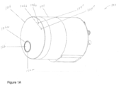
- Figures 1a to 1e show the AIRtrac TM sensor, that is generally indicated as 100 and may include an acoustic-based air probe like element 101.
- the acoustic-based air probe 101 may include an acoustic source generally indicated as 102 (see Figure 1d ) configured to provide an acoustic signal into a mixture of concrete; and an acoustic receiver generally indicated as 104 (see Figure 1e ) configured to be substantially co-planar with the acoustic source 102, to respond to the acoustic signal, and to provide signaling containing information about the acoustic signal injected into the mixture of concrete.
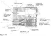
- the acoustic source 102 may consist of an arrangement of parts and components and is best shown in detail in Figure 1d .
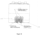
- the acoustic receiver 104 may consist of at least an arrangement of one or more transducers and fills and is best shown in Figure 1e .
- the acoustic-based air probe 101 may include a planar probing surface 106 having a first aperture 106a formed therein configured to receive part of the acoustic source 102, including a hardened steel piston 122, as best shown in Figure 1d .
- the hardened steel piston 122 is surrounded by a circumferential channel 122a, so as not to be in physical contact with the planar probing surface 106.
- the planar probing surface 106 may include at least one second aperture 106b, 106c formed therein configured to receive at least one part 104', 104" of the acoustic receiver 104.
- the part 104', 104" are shown as a protective polyurethane rubber member in Figure 1e .
- the planar probing surface 106 may be configured as a hardened steel face plate, although the scope of the invention is intended to include using other type or kinds of materials either now known or later developed in the future.
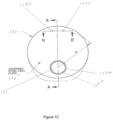
- the acoustic receivers 104 are configured in relation to the center of the hardened steel piston 122 of the acoustic source 102 and defined by a radius R, as best shown in Figure 1c , so that the acoustic receivers 104 are arranged and configured substantially on the circumference of a circle defined by the radius R from the center of the hardened steel piston 122.
- the acoustic receiver 104 may include, or take the form of, a dynamic pressure transducer, as best shown in Figure 1e .
- the acoustic receiver 104 may be configured to receive acoustic signals, e.g., having a frequency in a range of about 100-500 Hz, including 330 Hz, although the scope of the invention is intended to include using other frequencies .
- the acoustic source 102 may include, or take the form of, or be configured as, a floating mass, consistent with that shown in Figure 1d .
- the acoustic source 102 is shown in the form of a piston module assembly 120 having the rigid hardened steel piston 122 configured with a channel 124 to receive, or be coupled to, a piston shaft 126.
- the acoustic-based air probe 101 has a base plate disk 125 that contains the piston module assembly 120, as well as other components in Figure 1d .
- the rigid hardened steel piston 122 is enclosed, surrounded and configured to move in relation to a low durometer cast silicone rubber 123 and photo-etched flexures 127, so as to provide the floating mass aspect of the acoustic source 102.
- the low durometer cast silcone rubber 123 may also be configured to perform sealing functionality in relation to the mixture of the concrete.
- the acoustic source 102 may also include a vibration isolated actuator block assembly 128, best identified in Figure 1b , having a stationary voice coil actuator field assembly 130 in combination with a voice coil actuator field assembly 132 having an accelerometer transducer configuration.
- the vibration isolated actuator block assembly 128 may be configured to drive and vibrate the piston shaft 126, consistent with that shown in Figure 1d , so as to provide the acoustic signal to the mixture of the concrete when the acoustic-based air probe is inserted into the mixture.
- the apparatus 100 may also be configured with signal processing technology (not shown) for driving the acoustic source 102, as would be appreciated by a person skilled in the art.
- the acoustic-based air probe 101 may include a fluid/media temperature sensor 134, consistent with that shown in Figure 1d , configured to provide a temperature reading of the mixture.
- the acoustic-based air probe 101 may include a voice coil temperature sensor 136, consistent with that shown in Figure 1d , configured to provide a temperature reading of the stationary voice coil actuator field assembly 130.
- the acoustic-based air probe 101 may include two acoustic receivers 104, 104', that may take the form of the two dynamic pressure transducers, consistent with that shown in Figure 1e .
- the acoustic-based air probe 101 may include some combination of a connector/wiring cover plate 140, and various connectors configured in relation to the same, including a pressure sensor no. 1 connector 142 for providing the signaling in relation to one pressure sensor, a pressure sensor no. 2 connector 144 for providing the signaling in relation to the other pressure sensor, a voice coil drive connector 146 for providing the signaling in relation to the voice coil drive 130 ( Figure 1d ), a temperature sensor connector 148 for providing the signaling in relation to a temperature, and an accelerometer connector 150 for providing the signaling in relation to the voice coil actuator moving coil assembly 132 ( Figure 1d ), all shown in Figure 1b .
- a pressure sensor no. 1 connector 142 for providing the signaling in relation to one pressure sensor
- a pressure sensor no. 2 connector 144 for providing the signaling in relation to the other pressure sensor
- a voice coil drive connector 146 for providing the signaling in relation to the voice coil drive 130 ( Figure 1d )
- a temperature sensor connector 148 for providing the
- the present invention provides a new and unique system for determining a slump characteristic having an acoustic sensor and a signal processor.
- the present invention relates to a system according to claim 1. Further embodiments of the invention are given in the dependent claims.
- the system may include one or more of the following features:
- the acoustic sensor may include PVDF patches or PZT elements.
- the PVDF patches or PZT elements may be mounted on an exterior mixing drum wall of the mixing drum.
- the PVDF patches or PZT elements may be covered by an outer protective housing/cover, including where the outer protective housing/cover provides external noise protection.
- the signal processor is configured to determine the slump characteristic based upon noise characteristic at different spatial locations that indicate differences in the slump of the mixture of slurry.
- the vane of the mixing drum may be mounted on an interior wall of the mixing drum at an interior location, and the acoustic sensor is mounted on an exterior wall of the mixing drum at an exterior location corresponding to the interior location.
- the acoustic sensor may be configured to sense a first noise characteristic when the concrete is lifted by a vane of the mixing drum and provide first acoustic sensor signaling containing information about when the concrete is lifted by the vane, and sense a second noise characteristic when the concrete flows off the vane and falls back into the mixture and provide second acoustic sensor signaling containing information about when the concrete flows off the vane and falls back into the mixture; and the signal processor may be configured to receive the first acoustic sensor signaling and the second acoustic sensor signaling, and determine the corresponding signaling containing information about the slump characteristic of the mixture of concrete contained in the mixing drum, based upon the first acoustic sensor signaling and the second acoustic sensor signaling received.
- the signal processor may be configured to determine the slump characteristic based upon a post exit angle of the vane at which the release occurs.
- the signal processor may be configured to determine the slump characteristic based upon noise characteristics at different spatial locations that indicate differences in the slump.
- the acoustic sensor may be configured to sense the noise of the concrete flowing off a vane of the mixing drum, and provide first acoustic sensor signal containing information about the noise, and sense a dynamic noise of the remixing of the concrete falling back into the mixture, and provide second acoustic sensor signal containing information about the dynamic noise; and the signal processor may be configured to receive the first acoustic sensor signaling and the second acoustic sensor signaling, and determine the corresponding signaling containing information about the slump characteristic of the mixture of concrete contained in the mixing drum, based upon noise characteristics contained in the first acoustic sensor signaling and the second acoustic sensor signaling received.
- the signal processor may be configured to determine a high slump mix when the concrete in the mixture is lifted, then pours back off the vane into the mixture at a low post exit angle, and the noise is characterized by a broad band flow noise.
- the signal processor may be configured to determine a low slump mix when the concrete in the mixture is lifted, then pours back off the vane into the mixture at a high post exit angle, and the noise is characterized by discrete noise transients.
- the post exit angle may be determined by comparing first acoustic sensor signaling containing information about when the concrete is lifted by a scoop sampler of the mixing drum and second acoustic sensor signaling containing information about when the concrete flows off the scoop sampler and falls back into the mixture.
- the scoop sampler may be coated with a hydrophobic polymer.
- the acoustic sensor may include arrays of SONAR patches configured to sense a differential slurry speed at different locations caused by the motion of drum rotation and provide SONAR patch array signaling containing information about the differential slurry speed at different locations; and the signal processor may be configured to receive the SONAR patch array signaling, and determine the corresponding signaling containing information about the slump characteristic of the mixture of concrete contained in the mixing drum, based upon the SONAR patch array signaling received.
- the acoustic sensor may be mounted on an outside wall of the mixing drum.
- the acoustic sensor may be mounted on an inside wall of the mixing drum.
- the acoustic sensor may include an outside acoustic sensor mounted on an outside wall of the mixing drum, and an inside acoustic sensor mounted on an inside wall of the mixing drum.
- the acoustic sensor may include a first SONAR array mounted inside the mixing drum at a first depth and configured to sense a first flow rate of the concrete in the mixture at the first depth, and provide first SONAR array signaling containing information about the first flow rate, and a second SONAR array mounted inside the mixing drum at a second depth that is different than the first depth and configured to sense a second flow rate of the concrete in the mixture at the second depth, and provide second SONAR array signaling containing information about the second flow rate.
- the signal processor may be configured to receive the first SONAR array signaling and the second SONAR array signaling, and determine the corresponding signaling containing information about the slump characteristic of the mixture of concrete contained in the mixing drum, based upon the first SONAR array signaling and the second SONAR array signaling received.
- the slump characteristic may be based upon a differential flow characteristic sensed and determined.
- the acoustic sensor may include a first acoustic-based sensor and a second acoustic-based sensor configured to sense the speed of sound (SoS) in a mixture of concrete contained in a mixing drum in a plurality of different planes/directions.
- SoS speed of sound
- the system may also include a sensor housing assembly having a mounting wall configured to mount the sensor housing assembly on an interior wall of the mixing drum, a first sensor wall configured to mount the first acoustic-based sensor to sense a first SoS in the mixture of concrete contained in the mixing drum in a first plane/direction of the plurality of different planes/directions, and a second sensor wall configured to mount the second acoustic-based sensor to sense a second SoS in the mixture of concrete contained in the mixing drum in a second plane/direction of the plurality of different planes/directions.
- a sensor housing assembly having a mounting wall configured to mount the sensor housing assembly on an interior wall of the mixing drum, a first sensor wall configured to mount the first acoustic-based sensor to sense a first SoS in the mixture of concrete contained in the mixing drum in a first plane/direction of the plurality of different planes/directions, and a second sensor wall configured to mount the second acoustic-based sensor to sense a second SoS in the mixture
- the system may include, or take the form of, a multi-directional speed of sound (SoS) sensor.
- SoS speed of sound
- the first wall may be configured to face inwardly towards the axis of rotation; and the second wall may be configured to contact the mixture of concrete contained in the mixing drum on a leading edge facing the direction that the mixing drum is rotating.
- the second sensor wall may be obliquely-oriented in relation to the mounting wall and the second sensor wall.
- the first acoustic-based sensor may be configured to provide first acoustic-based sensor signaling containing information about a first acoustic signaling sensed at a first frequency.
- the first acoustic-based sensor may include a first acoustic transmitter configured to provide first acoustic transmitter signaling at the first frequency; and a first acoustic receiver configured to receive the first acoustic transmitter signaling and provide the first acoustic signaling sensed at the first frequency.
- the first acoustic transmitter may be configured to be substantially co-planar with the first acoustic receiver on the first sensor wall.
- the second acoustic-based sensor may be configured to provide second acoustic-based sensor signaling containing information about a second acoustic signaling sensed at a second frequency.
- the second acoustic-based sensor may include a second acoustic transmitter configured to provide second acoustic transmitter signaling at the second frequency; and a second acoustic receiver configured to receive the second acoustic transmitter signaling and provide the second acoustic signaling sensed at the second frequency.
- the second acoustic transmitter may be configured to be substantially co-planar with the second acoustic receiver on the second sensor wall.
- the first acoustic-based sensor may be configured to provide first acoustic-based sensor signaling containing information about a first acoustic signaling sensed at a first frequency.
- the system may include a first SoS processor configured to receive the first acoustic-based sensor signaling and provide first SoS processor signaling containing information about a first entrained air level that depends on a first SoS determination in the mixture of concrete contained in the mixing drum in the first plane/direction;
- the second acoustic-based sensor is configured to provide second acoustic-based sensor signaling containing information about a second acoustic signaling sensed at a second frequency;
- the system comprises a second SoS processor configured to receive the second acoustic-based sensor signaling and provide second SoS processor signaling containing information about a second entrained air level that depends on a second SoS determination in the mixture of concrete contained in the mixing drum in the second plane/direction.
- the system may include a slump factor processor configured to receive the first SoS processor signaling and second SoS processor signaling, and provide slump factor processor signaling containing information about a slump factor of the mixture of concrete contained in the mixing drum.
- the slump factor processor may be configured to determine the slump factor based upon a difference between the first SoS and the second SoS as a function of the rotation speed of the mixing drum.
- the slump factor processor may be configured to receive drum rotation speed signaling containing information about the rotation speed of the mixing drum and determine the slump factor based upon the rotation speed of the mixing drum.
- F SR a slump response factor
- the slump factor processor may be configured to determine the slump response factor (F SR ) based upon a calibration for various mix recipes and drum rotation speeds to provide an indicator of a real time slump in the mixture of concrete.
- the system may include a 3-axis accelerometer configured to respond to angular positions of the sensor housing assembly at given times, and provide angular position signaling containing information about the angular positions of the sensor housing assembly at the given times.
- the sensor may be mounted on a hatch door of the rotating container or drum, as well as other parts of the rotating container or drum.
- the signal processor is configured to receive signaling containing information about a noise characteristic of a mixture of a slurry, including concrete, contained in a mixing drum when rotating and sensed by an acoustic sensor mounted on a wall of the mixing drum, and determine corresponding signaling containing information about a slump characteristic of the mixture of concrete contained in the mixing drum, based upon the signaling received.
- the assignee's AIRtrac TM mobile sensor measures air content by actively creating acoustic waves and measuring the speed of the waves in the concrete media. This is accomplished by using a piston to "pulse" the concrete and measuring the amount of time it takes for the pulse to travel through the concrete and be detected by a pressure transducer that is known distance away from the piston, e.g., consistent with that set forth above. This works very well for the determination of the air content of the concrete mixture but these components can also be used to measure other aspects of the concrete.
- the present disclosure sets forth two additional measurements that can be made and used to determine information about the slurry, including concrete.
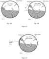
- Figure 4 shows an approximately half full drum.
- the AIRtrac TM sensor will enter the concrete at about +90 degrees from vertical and exit at about -90 degrees. This will give an indication that the concrete is occupying about 1 ⁇ 2 the drum and the volume can be calculated. A simple calculation can be made for other concrete entry/exit angles to yield volume.
- the angle of the sensor is always available so the remaining aspect of the measurement is determination of the concrete entry and exit points.
- Two ways this can be accomplished utilize the pressure transducer.
- a static pressure can indicate when the sensor is under concrete. While in air above the concrete the pressure transducer will show close to 0 pressure, but as the senor enters the concrete the weight of the concrete will cause a pressure reading. This reading will increase until the sensor is at the bottom of the drum and then decrease until the sensor emerges from the concrete on the other side.
- Various analysis techniques including least squares curve fitting can be used to extrapolate the exact entry and exit points of the pressure sensor.
- a second detection technique can utilize the magnitude of the acoustic signal the pressure sensor sees as it is generated by the piston.
- Air is highly attenuative to acoustic waves so when the AIRtrac TM is in air the pressure transducer will see very little of the acoustic energy generated by the piston, while once the sensor is in the concrete the signal level will rise dramatically. This can also be used to determine when the AIRtrac TM sensor enters and leaves the concrete within the drum.
- a second parameter of the concrete that the AIRtrac TM can determine is the viscosity of the concrete.
- the viscosity of a fluid is directly related to the ability of the fluid to flow. Therefore, in a rotating container or drum like a concrete truck a low viscosity fluid will remain very level while a very viscous fluid will tend to not flow very well and will ride up the wall of the drum as the drum exits the fluid.
- Figure 5 shows diagrams of the effect.
- the amount of the "tilt" of the concrete in the drum will depend on the viscosity of the fluid (or concrete) and the speed of rotation of the drum.
- the drum rotation speed can be determined by the 3-axis accelerometer and the "tilt" can be determined by the same techniques described above. With knowledge of these parameters along with geometric shape of the drum the concrete viscosity can be determined. Furthermore, with knowledge of the concrete constituents including amount of water, sand, rock and their respective densities, the slump of the concrete can be determined.
- CCS-0183 Figures 6-12: Simultaneous Concrete Slump and Speed of Sound Monitoring for Readymix Delivery Trucks (not forming part of the claimed invention)
- the assignee's new AIRtrac TM sensor design can be incorporated internal to a drum mixer to simultaneously determine both the entrained air and slump of the concrete slurry, e.g., based on a determination of the speed of sound (SoS) in the slurry in two, or a plurality of planes - termed here a Multi-Direction SoS - MDSoS - sensor.
- SoS speed of sound
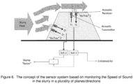
- Figure 6 which illustrates the two axis concept:
- the AIRtrac TM sensor unit as described in the aforementioned patent application serial no. 14/350,711 (712-2.365-1-1), may be used as the basis of the SoS measurement.
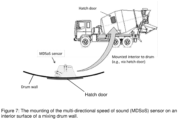
- the device shown in Figure 6 would be internally integrated into a readymix truck drum, via the drum hatch door, for example, as illustrated in Figure 7 .
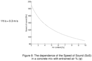
- the speed of sound in a concrete mix is a function of the entrained air level, and has been used as the basis of a device for such monitoring purposes in concrete mixes (see the reference labeled [9] below).
- the device emits a sound signal into the concrete slurry mix at a given frequency, set of frequencies, or is scanned over a range of frequencies.
- This acoustic signal is then detected at a receiver, or a plurality of receivers (e.g., a microphone or pressure transducer) that are physically offset from the transmitter, and the speed of sound in the slurry assessed.
- the speed of sound, c is approximately inversely proportional to the square root of the entrained air level (or Air Void Fraction, ( ⁇ ), as illustrated in Figure 8 .
- the MDSoS sensor elements in this case 2 units
- the MDSoS sensor elements labeled as AIRtrac TM #1 and AIRtrac TM #2
- the slurry ahead of the MDSoS sensor housing will undergo compressive forces due to the flow resistance experienced in moving (flowing) around the housing assembly (as depicted by the slurry flow arrows in Figure 7 ).
- the compressive forces will be dependent on the slump, or 'workability' of the concrete slurry. Consequently, for a given drum rotation speed, the difference in the SoS monitored for the two AIRtrac TM sensor modules/units will be inversely related to the slump in the concrete. In addition, the compressive forces will be proportional to the drum rotation speed, so this would be required to be monitored to allow for a calibration factor to be attained, which allows the slump factor to be determined at any non-zero rotational speed.
- FIG 10 shows the modelled dependency of the difference in observed SoS at the two AIRtrac TM sensors for a range of different entrained air values, and at a nominal rotational speeds ⁇ , and 2 ⁇ (characterized such that at the rotational speed of ⁇ , the high slump mix experiences a compression pressure at the leading face of the sensor housing of ⁇ 0.1 Bar, and the low slump experiences a compression pressure at the leading face of the sensor housing of ⁇ 0.5 Bar).
- the other parameters - density etc. are typical of the values associated with concrete slurry.
- the drum rotational speed thus serves as a modulator of the difference in the SoS values.
- a calibration formula or table would need to be created, allowing the slump to be determined from the difference SoS measurements and for various entrained air mixes.
- multiplying the difference in SoS measurements by the square-root of the entrained air level produces a response graph as shown in Figure 11 .
- the mixing of the slurry in a concrete mixer drum is driven by the blades or vanes that create a 'churn' in the slurry, e.g., consistent with that shown in Figures 14-16 .
- the primary purpose of the blades is to lift the slurry (or slurry components initially) as the drum rotates. With each rotation, the lifted slurry drops back into the mixer at the bottom of the drum, creating a mixing dynamic and the cycle repeats again.
- the noise characteristics generated by the mixing slurry will also thus be slump dependent.
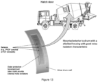
- Figure 13 shows a readymix concrete truck having a mixer drum wall with one or more sensors attached thereto.
- the sensors may be mounted to the mixer drum wall with a shield housing with good noise isolation characteristics.
- the sensors may also have an outer protective housing/cover (which may also provide an external noise isolation.
- the sensors may include, or take the form of, e.g., PVDF "patches" or PZT elements.
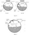
- Figure 14 shows a mixer drum having mixer vanes configured therein for mixing slurry contained in the mixer drum. Consistent with that shown in Figure 14 , the slurry is 'lifted' by the action of the vanes as the drum turns.
- the 'lifted' slurry is ultimately released as the drum turns and depending on the slump, it 'flows' off, or 'tumbles' off the vanes and back into the slurry (mixing process).
- the slump of the slurry will play a significant role in the dynamics:
- Figure 15 shows a mixer drum having mixer vanes configured therein for mixing slurry contained in the mixer drum.
- the mixer drum also has an acoustic sensor array, e.g., like that shown in Figure 13 .
- the sensor array may be positioned to detect both the noise of the slurry flowing off the vanes, and the dynamics of the 'remixing'.
- the slump of the slurry will impact the noise characteristics.
- Figure 16 includes Figs. 16A and 16B , which shows an example of the acoustic impact in relation to high slump and low slump.
- the 'churn' effect of the vanes is an important component of the slurry mixing process, but the dynamics are slump-dependent.
- the acoustic sensor array will sense noise that is a broader band 'flow' noise.
- the acoustic sensor array will sense noise that is characterized by more discrete noise transients.
- Figure 17 Alternatives: Scoop Sampler
- Figure 17 shows a mixer drum having scoop samplers configured on its inside wall and a sensor, e.g., like a SONAR patch, mounted on its outside wall.
- a sensor e.g., like a SONAR patch
- the scoops' are added to extract a sample of slurry as the drum rotates.
- the walls of scoop may be coated with a hydrophobic polymer (e.g., like polyurethane (PU)) to allow clean release of sample.
- a hydrophobic polymer e.g., like polyurethane (PU)
- the scoops may include a 'lip' to create the resistance to flow-out.
- the mixer drum may be configured to detect the point (i.e., the drum rotation angle) at which the slurry flows out of the scoop sampler.
- the measurement approach may include using a passive acoustic array, e.g., like the SONAR patch shown.
- the acoustics of this create a frequency or transient type of signature that gives a measure of the concrete slump - use a microphone (or PVDF strip) in AIRtrac TM assembly to monitor.
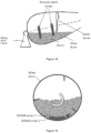
- Figure 18 shows a mixer drum having mixer vanes for mixing a slurry contained therein, as well as acoustic patch arrays configured or mounted on the outside wall of the mixer drum.
- the mixing drum is mounted on a mixing drum mount as shown.
- the motion of the drum rotation creates an effective differential slurry flow speed at different locations along the drum that could be sensed or picked up by the acoustic patch arrays as shown.
- the acoustic patch arrays may include, or take the form of, SONAR type external patch arrays.
- the acoustic patch arrays may be positioned internally under one or more PU layers.
- characteristics at different 'depths' in the slurry, and different drum RPMs may also be detected and monitored.
- Figure 19 shows a mixer drum having scoops configured therein, as well as two SONAR arrays 1 and 2 configured or mounted on the inside of the mixer drum, e.g., at different depths as shown.
- the SONAR array 1 is mounted on the inside wall of the mixer drum at a first depth
- the SONAR array 1 is mounted inside of the mixer drum at a second depth.
- the two SONAR arrays 1 and 2 are separated by a standoff depth indicated by an arrow labeled D.
- the scoops' are added to extract a sample of slurry as the drum rotates.
- walls of the scoops may be coated with hydrophobic polymer (e.g., like PU) to allow clean release of sample from the scoop.
- hydrophobic polymer e.g., like PU
- the SONAR array(s) may be used to monitor the slurry flow rate with the drum rotation at the drum surface (e.g., using SONAR array 1), and at one or more standoff depths D into the slurry (e.g., using SONAR array 2).
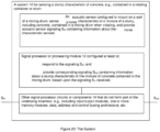
- Figure 20 shows a system 10 having a sensor (e.g., such as an acoustic-based sensor like element 100, or a PVDF sensor, or a PZT sensor, or a SONAR array sensor) and a signal processor or signal processing module 12 for implementing the present invention.
- a sensor e.g., such as an acoustic-based sensor like element 100, or a PVDF sensor, or a PZT sensor, or a SONAR array sensor
- a signal processor or signal processing module 12 for implementing the present invention.
- the senor 100 or the PVDF sensor, or the PZT sensor, or the SONAR array sensor may be configured to mount on a wall of a mixing drum like that shown in Figures 6 , 7 , 9 and 13-19 , sense a noise characteristic of a mixture of a slurry, including concrete, contained in a mixing drum when rotating, and provide acoustic sensor signaling containing information about the noise characteristic sensed.
- the signal processor 12 may be configured to receive the acoustic sensor signaling, and determine corresponding signaling containing information about a slump characteristic of the mixture of concrete contained in the mixing drum, based upon the signaling received.
- the functionality of the signal processor or processor control module 12 may be implemented using hardware, software, firmware, or a combination thereof.
- the processor module may include one or more microprocessor-based architectures having a microprocessor, a random access memory (RAM), a read only memory (ROM), input/output devices and control, data and address buses connecting the same, e.g., consistent with that shown in Figure 20 , e.g., see element 14.
- the input/output devices may be configured to receive the signaling S in sensed by the sensor 100, the PVDF sensor, the PZT sensor, and provide the signaling S in to the signal processor 12 for further processing.
- the input/output devices may be configured to receive the corresponding signaling S out from the signal processor 12, and provide the corresponding signaling S out .
- the present invention is disclosed based upon using the assignee's AIRtrac TM sensor.
- the scope of the invention is not intended to be limited to the same.
- embodiments are envisioned, and the scope of the invention is intended to include, e.g. using other types or kinds of acoustic-based sensors that may be configured to attach inside a rotating container or drum having a known geometry, sense angular positions of the sensor and sense associated entry and exit points when the sensor enters and exits concrete contained in the rotating container or drum, and provide signaling containing information about the angular positions and the associated entry and exit points.
- the present invention is disclosed based upon using a rotating drum forming part of a concrete mixing truck.
- the scope of the invention is not intended to be limited to the same.
- embodiments are envisioned, and the scope of the invention is intended to include, e.g. using other types or kinds of rotating containers or drums that may be configured to receive and contain concrete, as well as rotate and mix the concrete.
- the Slurry (e.g., Concrete)
- the present invention is disclosed based upon mixing a slurry like concrete using a rotating drum.
- the scope of the invention is not intended to be limited to the same.
- embodiments are envisioned, and the scope of the invention is intended to include, e.g. processing other types or kinds of slurries, including other types or kinds of slurries that are sensitive to the amount of entrained air contained therein, other types or kinds of or slurries that are mixed and poured from a rotating container or drum.
- the senor may include a sensor housing that may be fastened inside the rotating container or drum using fasteners like screws.
- PVDF technology including PVDF “patches”, as well as PZT technology including PZT elements, are known in the art, and the scope of the invention is not intended to be limited to any particular type or kind thereof.
Landscapes
- Chemical & Material Sciences (AREA)
- Physics & Mathematics (AREA)
- Health & Medical Sciences (AREA)
- Life Sciences & Earth Sciences (AREA)
- Engineering & Computer Science (AREA)
- Biochemistry (AREA)
- Analytical Chemistry (AREA)
- General Health & Medical Sciences (AREA)
- General Physics & Mathematics (AREA)
- Immunology (AREA)
- Pathology (AREA)
- Ceramic Engineering (AREA)
- Chemical Kinetics & Catalysis (AREA)
- Acoustics & Sound (AREA)
- Food Science & Technology (AREA)
- Structural Engineering (AREA)
- Mechanical Engineering (AREA)
- Medicinal Chemistry (AREA)
- Dispersion Chemistry (AREA)
- Signal Processing (AREA)
- Preparation Of Clay, And Manufacture Of Mixtures Containing Clay Or Cement (AREA)
- Investigating Or Analyzing Materials By The Use Of Ultrasonic Waves (AREA)
Description
- This application claims benefit to provisional patent application serial nos.
62/548,699 (712-2.452//CCS-0178), 62/548,712 (712-2.453//CCS-0183), 62/548,727 (712-2.454//CCS-0185), all filed on 22 August 2017 - This application is related to patent application serial no.
14/350,711 (712-2.365-1-1), filed 9 April 2014 PCT/US2012/060822, filed 18 October 2012 , claiming benefit to provisional patent application serial nos.61/548,549 61/548,563, both filed 18 October 2011 - The aforementioned applications were all assigned to the assignee of the present application, which builds on this family of technology.
- This invention relates to a technique for sensing parameters of concrete in a rotating container or drum, e.g., including a slump characteristic.
- The measurement of concrete slump in readymix delivery is an important quality parameter that both the supplier and the customer need to know at the point of delivery. This is done most often manually using a cone-shaped instrument, known as an Abram's cone. Recently, there has been growing interest in the real-time measurement of another crucial parameter - entrained air in both central mixers for pre-fabricated concrete, and readymix deliveries.
- Several patents have described systems for the use of automated methods for providing a measure of the slump in a concrete delivery truck. These include the use of methods to monitor the power/torque or hydraulic pressure required to drive the drum (
US Patent No. 3,731,909 ,US Patent No. 4,008,093 ,US Patent No. 5,713,663 ,US Patent No. 8,020,431 (see references labeled [1] - [4] below), the use of a probe internal to the drum for measuring the resistance to flow in the concrete slurry (US Patent No. 8,858,061 ,US 9 Patent No.,199,391 (see references labeled [5] and [6] below) and an approach based on the determination of the slurry surface angle relative to the horizontal plane in a rotating drum mixer, as determined via the as termed 'banking angle' in US patent publication no.US 2009/0171595 (see reference labeled [7] below). Approaches to remotely monitor and communicate the concrete status in real-time have also been described, as inUS Patent No. 6,484,079 (see references labeled [8] below).US 2017/217047 A1 describes a system and method involving use of a sensor-containing body provided with a sonar emitter and a sonar detector which is mounted and/or rotatably disposed along the longitudinal rotational axis of a concrete mixer drum at the close end, the sensor-containing body being connected to a conduit for introducing water, chemical admixture, gas, and/or cleansing fluid through the closed end of the drum into the mixer drum (see references labeled [10] below).WO 2013/188620 A2 discloses an apparatus comprising a signal processing module configured with at least one processor and at least one memory including computer program code, the at least one memory and computer program code configured, with the at least one processor, to cause the apparatus at least to: receive signaling containing information about a stiffness of a concrete mixture; and determine an average bubble size of gas contained in the concrete mixture, based at least partly on the signaling received (see references labeled [11] below). - The assignee of the present invention has developed a means of measuring entrained air in wet concrete, which is disclosed in the aforementioned patent application serial no.
14/350,711 - Consistent with that disclosed in the aforementioned patent application serial no.
14/350,711 Figures 1a to 1e show the AIRtrac™ sensor, that is generally indicated as 100 and may include an acoustic-based air probe like element 101. The acoustic-based air probe 101 may include an acoustic source generally indicated as 102 (seeFigure 1d ) configured to provide an acoustic signal into a mixture of concrete; and an acoustic receiver generally indicated as 104 (seeFigure 1e ) configured to be substantially co-planar with the acoustic source 102, to respond to the acoustic signal, and to provide signaling containing information about the acoustic signal injected into the mixture of concrete. By way of example, the acoustic source 102 may consist of an arrangement of parts and components and is best shown in detail inFigure 1d . By way of example, the acoustic receiver 104 may consist of at least an arrangement of one or more transducers and fills and is best shown inFigure 1e . - The acoustic-based air probe 101 may include a
planar probing surface 106 having a first aperture 106a formed therein configured to receive part of the acoustic source 102, including a hardenedsteel piston 122, as best shown inFigure 1d . At the interface with theplanar probing surface 106, the hardenedsteel piston 122 is surrounded by a circumferential channel 122a, so as not to be in physical contact with theplanar probing surface 106. Theplanar probing surface 106 may include at least one second aperture 106b, 106c formed therein configured to receive at least one part 104', 104" of the acoustic receiver 104. The part 104', 104" are shown as a protective polyurethane rubber member inFigure 1e . Theplanar probing surface 106 may be configured as a hardened steel face plate, although the scope of the invention is intended to include using other type or kinds of materials either now known or later developed in the future. The acoustic receivers 104 are configured in relation to the center of the hardenedsteel piston 122 of the acoustic source 102 and defined by a radius R, as best shown inFigure 1c , so that the acoustic receivers 104 are arranged and configured substantially on the circumference of a circle defined by the radius R from the center of the hardenedsteel piston 122. - The acoustic receiver 104 may include, or take the form of, a dynamic pressure transducer, as best shown in
Figure 1e . - In operation, and by way of example, the acoustic receiver 104 may be configured to receive acoustic signals, e.g., having a frequency in a range of about 100-500 Hz, including 330 Hz, although the scope of the invention is intended to include using other frequencies.
- By way of example, the acoustic source 102 may include, or take the form of, or be configured as, a floating mass, consistent with that shown in
Figure 1d . - In
Figure 1d , the acoustic source 102 is shown in the form of apiston module assembly 120 having the rigid hardenedsteel piston 122 configured with a channel 124 to receive, or be coupled to, a piston shaft 126. The acoustic-based air probe 101 has a base plate disk 125 that contains thepiston module assembly 120, as well as other components inFigure 1d . The rigid hardenedsteel piston 122 is enclosed, surrounded and configured to move in relation to a low durometer cast silicone rubber 123 and photo-etched flexures 127, so as to provide the floating mass aspect of the acoustic source 102. The low durometer cast silcone rubber 123 may also be configured to perform sealing functionality in relation to the mixture of the concrete. The acoustic source 102 may also include a vibration isolated actuator block assembly 128, best identified inFigure 1b , having a stationary voice coil actuator field assembly 130 in combination with a voice coil actuator field assembly 132 having an accelerometer transducer configuration. The vibration isolated actuator block assembly 128 may be configured to drive and vibrate the piston shaft 126, consistent with that shown inFigure 1d , so as to provide the acoustic signal to the mixture of the concrete when the acoustic-based air probe is inserted into the mixture. Theapparatus 100 may also be configured with signal processing technology (not shown) for driving the acoustic source 102, as would be appreciated by a person skilled in the art. - The acoustic-based air probe 101 may include a fluid/media temperature sensor 134, consistent with that shown in
Figure 1d , configured to provide a temperature reading of the mixture. - The acoustic-based air probe 101 may include a voice coil temperature sensor 136, consistent with that shown in
Figure 1d , configured to provide a temperature reading of the stationary voice coil actuator field assembly 130. - The acoustic-based air probe 101 may include two acoustic receivers 104, 104', that may take the form of the two dynamic pressure transducers, consistent with that shown in
Figure 1e . - The acoustic-based air probe 101 may include some combination of a connector/wiring cover plate 140, and various connectors configured in relation to the same, including a pressure sensor no. 1 connector 142 for providing the signaling in relation to one pressure sensor, a pressure sensor no. 2 connector 144 for providing the signaling in relation to the other pressure sensor, a voice coil drive connector 146 for providing the signaling in relation to the voice coil drive 130 (
Figure 1d ), a temperature sensor connector 148 for providing the signaling in relation to a temperature, and an accelerometer connector 150 for providing the signaling in relation to the voice coil actuator moving coil assembly 132 (Figure 1d ), all shown inFigure 1b . - In its broadest sense, the present invention provides a new and unique system for determining a slump characteristic having an acoustic sensor and a signal processor.
- The present invention relates to a system according to
claim 1. Further embodiments of the invention are given in the dependent claims. - The system may include one or more of the following features:
The acoustic sensor may include PVDF patches or PZT elements. - The PVDF patches or PZT elements may be mounted on an exterior mixing drum wall of the mixing drum.
- The PVDF patches or PZT elements may be covered by an outer protective housing/cover, including where the outer protective housing/cover provides external noise protection.
- The signal processor is configured to determine the slump characteristic based upon noise characteristic at different spatial locations that indicate differences in the slump of the mixture of slurry.
- The vane of the mixing drum may be mounted on an interior wall of the mixing drum at an interior location, and the acoustic sensor is mounted on an exterior wall of the mixing drum at an exterior location corresponding to the interior location.
- The acoustic sensor may be configured to sense a first noise characteristic when the concrete is lifted by a vane of the mixing drum and provide first acoustic sensor signaling containing information about when the concrete is lifted by the vane, and sense a second noise characteristic when the concrete flows off the vane and falls back into the mixture and provide second acoustic sensor signaling containing information about when the concrete flows off the vane and falls back into the mixture; and the signal processor may be configured to receive the first acoustic sensor signaling and the second acoustic sensor signaling, and determine the corresponding signaling containing information about the slump characteristic of the mixture of concrete contained in the mixing drum, based upon the first acoustic sensor signaling and the second acoustic sensor signaling received.
- The signal processor may be configured to determine the slump characteristic based upon a post exit angle of the vane at which the release occurs.
- The signal processor may be configured to determine the slump characteristic based upon noise characteristics at different spatial locations that indicate differences in the slump.
- The acoustic sensor may be configured to sense the noise of the concrete flowing off a vane of the mixing drum, and provide first acoustic sensor signal containing information about the noise, and sense a dynamic noise of the remixing of the concrete falling back into the mixture, and provide second acoustic sensor signal containing information about the dynamic noise; and the signal processor may be configured to receive the first acoustic sensor signaling and the second acoustic sensor signaling, and determine the corresponding signaling containing information about the slump characteristic of the mixture of concrete contained in the mixing drum, based upon noise characteristics contained in the first acoustic sensor signaling and the second acoustic sensor signaling received.
- The signal processor may be configured to determine a high slump mix when the concrete in the mixture is lifted, then pours back off the vane into the mixture at a low post exit angle, and the noise is characterized by a broad band flow noise.
- The signal processor may be configured to determine a low slump mix when the concrete in the mixture is lifted, then pours back off the vane into the mixture at a high post exit angle, and the noise is characterized by discrete noise transients.
- The post exit angle may be determined by comparing first acoustic sensor signaling containing information about when the concrete is lifted by a scoop sampler of the mixing drum and second acoustic sensor signaling containing information about when the concrete flows off the scoop sampler and falls back into the mixture.
- The scoop sampler may be coated with a hydrophobic polymer.
- According to an embodiment not forming part of the claimed invention, the acoustic sensor may include arrays of SONAR patches configured to sense a differential slurry speed at different locations caused by the motion of drum rotation and provide SONAR patch array signaling containing information about the differential slurry speed at different locations; and the signal processor may be configured to receive the SONAR patch array signaling, and determine the corresponding signaling containing information about the slump characteristic of the mixture of concrete contained in the mixing drum, based upon the SONAR patch array signaling received.
- The acoustic sensor may be mounted on an outside wall of the mixing drum.
- The acoustic sensor may be mounted on an inside wall of the mixing drum.
- The acoustic sensor may include an outside acoustic sensor mounted on an outside wall of the mixing drum, and an inside acoustic sensor mounted on an inside wall of the mixing drum.
- According to an embodiment not forming part of the claimed invention, the acoustic sensor may include a first SONAR array mounted inside the mixing drum at a first depth and configured to sense a first flow rate of the concrete in the mixture at the first depth, and provide first SONAR array signaling containing information about the first flow rate, and a second SONAR array mounted inside the mixing drum at a second depth that is different than the first depth and configured to sense a second flow rate of the concrete in the mixture at the second depth, and provide second SONAR array signaling containing information about the second flow rate. In addition, the signal processor may be configured to receive the first SONAR array signaling and the second SONAR array signaling, and determine the corresponding signaling containing information about the slump characteristic of the mixture of concrete contained in the mixing drum, based upon the first SONAR array signaling and the second SONAR array signaling received.
- The slump characteristic may be based upon a differential flow characteristic sensed and determined.
- According to an embodiment not forming part of the claimed invention, the acoustic sensor may include a first acoustic-based sensor and a second acoustic-based sensor configured to sense the speed of sound (SoS) in a mixture of concrete contained in a mixing drum in a plurality of different planes/directions. In addition, the system may also include a sensor housing assembly having a mounting wall configured to mount the sensor housing assembly on an interior wall of the mixing drum, a first sensor wall configured to mount the first acoustic-based sensor to sense a first SoS in the mixture of concrete contained in the mixing drum in a first plane/direction of the plurality of different planes/directions, and a second sensor wall configured to mount the second acoustic-based sensor to sense a second SoS in the mixture of concrete contained in the mixing drum in a second plane/direction of the plurality of different planes/directions.
- The system may include, or take the form of, a multi-directional speed of sound (SoS) sensor.
- The first wall may be configured to face inwardly towards the axis of rotation; and the second wall may be configured to contact the mixture of concrete contained in the mixing drum on a leading edge facing the direction that the mixing drum is rotating.
- The second sensor wall may be obliquely-oriented in relation to the mounting wall and the second sensor wall.
- The first acoustic-based sensor may be configured to provide first acoustic-based sensor signaling containing information about a first acoustic signaling sensed at a first frequency.
- The first acoustic-based sensor may include a first acoustic transmitter configured to provide first acoustic transmitter signaling at the first frequency; and a first acoustic receiver configured to receive the first acoustic transmitter signaling and provide the first acoustic signaling sensed at the first frequency.
- The first acoustic transmitter may be configured to be substantially co-planar with the first acoustic receiver on the first sensor wall.
- The second acoustic-based sensor may be configured to provide second acoustic-based sensor signaling containing information about a second acoustic signaling sensed at a second frequency.
- The second acoustic-based sensor may include a second acoustic transmitter configured to provide second acoustic transmitter signaling at the second frequency; and a second acoustic receiver configured to receive the second acoustic transmitter signaling and provide the second acoustic signaling sensed at the second frequency.
- The second acoustic transmitter may be configured to be substantially co-planar with the second acoustic receiver on the second sensor wall.
- The first acoustic-based sensor may be configured to provide first acoustic-based sensor signaling containing information about a first acoustic signaling sensed at a first frequency.
- According to an embodiment not forming part of the claimed invention, the system may include a first SoS processor configured to receive the first acoustic-based sensor signaling and provide first SoS processor signaling containing information about a first entrained air level that depends on a first SoS determination in the mixture of concrete contained in the mixing drum in the first plane/direction; the second acoustic-based sensor is configured to provide second acoustic-based sensor signaling containing information about a second acoustic signaling sensed at a second frequency; and the system comprises a second SoS processor configured to receive the second acoustic-based sensor signaling and provide second SoS processor signaling containing information about a second entrained air level that depends on a second SoS determination in the mixture of concrete contained in the mixing drum in the second plane/direction.
- The system may include a slump factor processor configured to receive the first SoS processor signaling and second SoS processor signaling, and provide slump factor processor signaling containing information about a slump factor of the mixture of concrete contained in the mixing drum.
- The slump factor processor may be configured to determine the slump factor based upon a difference between the first SoS and the second SoS as a function of the rotation speed of the mixing drum.
- The slump factor processor may be configured to receive drum rotation speed signaling containing information about the rotation speed of the mixing drum and determine the slump factor based upon the rotation speed of the mixing drum.
- The slump factor processor may be configured to determine a slump response factor (FSR) for a rotational speed (ω) by multiplying the difference by a square-root of the first SoS measured based upon the equation:

- The slump factor processor may be configured to determine the slump response factor (FSR) based upon a calibration for various mix recipes and drum rotation speeds to provide an indicator of a real time slump in the mixture of concrete.
- The system may include a 3-axis accelerometer configured to respond to angular positions of the sensor housing assembly at given times, and provide angular position signaling containing information about the angular positions of the sensor housing assembly at the given times.
- The sensor may be mounted on a hatch door of the rotating container or drum, as well as other parts of the rotating container or drum.
- According to the invention, the signal processor is configured to receive signaling containing information about a noise characteristic of a mixture of a slurry, including concrete, contained in a mixing drum when rotating and sensed by an acoustic sensor mounted on a wall of the mixing drum, and determine corresponding signaling containing information about a slump characteristic of the mixture of concrete contained in the mixing drum, based upon the signaling received.
- The drawing includes
Figures 1a - 20 , which are not necessarily drawn to scale, as follows: -
Figure 1a is a perspective view of an acoustic probe that may be used in some embodiments of the present invention. -
Figure 1b is an axial view of one end the acoustic probe shown inFigure 1a . -
Figure 1c is an axial view of another end the acoustic probe shown inFigure 1a . -
Figure 1d is a sectional view of the end the acoustic probe shown inFigure 1c along section lines A-A. -
Figure 1e is a sectional view of the end the acoustic probe shown inFigure 1c along section lines B-B. -
Figure 2 is a photograph of a ready mix truck with arrow pointing to hatch door indicating potential location of AIRtrac™ sensor installation, which is provided as an example of an AIRtrac™ system installed on a hatch door, and where the hatch door may be located on mixer drum. -
Figure 3 is a photograph of a hatch door with AIRtrac™ sensor installed. -
Figure 4 is a diagram showing an end cross-section of a concrete truck drum having an AIRtrac™ sensor entering and exiting the concrete as the concrete truck drum. -
Figure 5 includesFigs 5A and 5B , whereFig. 5A is a diagram showing an end cross-section of a concrete truck drum with concrete having a low viscosity; and whereFig. 5B is a diagram showing the end cross-section of the concrete truck drum with concrete having a high viscosity. -
Figure 6 is a diagram of a sensor system not forming part of the claimed invention based on monitoring the speed of sound (SoS) in the slurry in a plurality of planes/directions, e.g., using an acoustic based sensor like the assignee's AIRtrac™ sensor. -
Figure 7 is a diagram showing the mounting of the multi-directional SoS (MDSoS) sensor on an interior surface of a mixing drum wall. -
Figure 8 is a graph of speed of sound (ft/sec) (1 ft/sec = 0.3 m/sec) versus air content (%), showing the dependence of the SoS in a concrete mix with entrained air % (ϕ). -
Figure 9 is a diagram showing the measurement of SoS by two AIRtrac™ sensors/modules at a leading face of a sensor housing and above the sensor housing as it moves through the concrete slurry. -
Figure 10 is a graph of the difference in the measured SoS (Sos2 - SoS1) in Ft/sec versus entrained air level in mix (%) for two drum speed of ω and 2ω, where the difference is measured by two AIRtrac™ sensors/modules (SoS2 measured at the leading face of the sensor housing via AIRtrac™ #2 and SoS1 measured above the sensor housing via AIRtrac™ #1 (SoS1)), and the entrained air content measured via AIRtrac™ #1 (SoS1). -
Figure 11 is a graph of ΔSoS(C2 - C1)*SQRT(ϕ) versus entrained air level in mix (AIRtrac#1) for two drum speed of ω and 2ω, showing the difference in the modelled SoS by the two AIRTrac modules (SoS2 measured at the leading face of the sensor housing via AIRtrac™ #2 and SoS1 measured above the sensor housing via AIRtrac™ #1 (SoS1)) multiplied by the SQRT of the entrained air in the mix (as measured via AIRtrac #1 (SoS1)) Vs the entrained air in the mix. -
Figure 12 is a graph of the slump factor (FSR(ω) = (c2(ω) -c1) * ϕ1/2) versus drum rotation rate (ω), showing a modeled dependence of the Slump Response Factor (FSR) on the drum rotation rate for 4 different modeled slump mixes, including a low slump, a med-hi slump, a med-low slump and hi slump. -
Figure 13 shows a diagram of a readymix concrete truck having a mixer drum wall with one or more sensors attached thereto. -
Figure 14 includesFigs 14A and 14B having diagrams showing a mixer drum with mixer vanes configured therein for mixing slurry contained in the mixer drum, e.g., by lifting and releasing the slurry. -
Figure 15 is a diagram showing a mixer drum having an acoustic sensor array arranged on an outside wall, and having mixer vanes configured therein for mixing slurry contained in the mixer drum, where the acoustic sensor array is positioned to detect the noise of the slurry flowing off the vanes and the dynamic of the remixing. -
Figure 16 includesFigs. 16A and 16B having diagrams with an example of the acoustic impact in relation to high slump and low slump. -
Figure 17 is a diagram showing a mixer drum having scoop samplers configured on its inside wall and a sensor, e.g., like a SONAR patch, mounted on its outside wall. -
Figure 18 is a diagram showing a mixer drum having mixer vanes for mixing a slurry contained therein, as well as acoustic patch arrays configured or mounted on the outside wall of the mixer drum. -
Figure 19 is a diagram showing a mixer drum having scoops configured therein, as well as twoSONAR arrays -
Figure 20 is a block diagram of a system having a sensor and a signal processor or signal processing module for implementing the present invention. - According to some embodiments, and consistent with that shown in
Figures 1a - 5 , the assignee's AIRtrac™ mobile sensor measures air content by actively creating acoustic waves and measuring the speed of the waves in the concrete media. This is accomplished by using a piston to "pulse" the concrete and measuring the amount of time it takes for the pulse to travel through the concrete and be detected by a pressure transducer that is known distance away from the piston, e.g., consistent with that set forth above. This works very well for the determination of the air content of the concrete mixture but these components can also be used to measure other aspects of the concrete. The present disclosure sets forth two additional measurements that can be made and used to determine information about the slurry, including concrete. - One parameter that is often not known is the precise volumetric amount of concrete that is in a concrete truck, particularly after a partial pour has occurred. Some measurement techniques known in the art look at the hydraulic loading of the drum, however this is often inaccurate as it requires knowledge of the exact density of the concrete as well as the knowledge of other parameters such as the air content. Using the AIRtrac™ system a much more direct measurement can be made. This measurement technique utilizes the fact that the AIRtrac™ sensor is submerged under the concrete for part of the drums rotation and then is out of the concrete for the remainder. In addition, the AIRtrac™ device has a 3-axis accelerometer that is used to determine the angular position of the sensor at any given time. The combination of knowing the concrete entry and exit angles along with the geometry of the drum, the volume of the concrete can be calculated.
Figure 4 shows a diagram of how this can be achieved. -
Figure 4 shows an approximately half full drum. The AIRtrac™ sensor will enter the concrete at about +90 degrees from vertical and exit at about -90 degrees. This will give an indication that the concrete is occupying about ½ the drum and the volume can be calculated. A simple calculation can be made for other concrete entry/exit angles to yield volume. - The angle of the sensor is always available so the remaining aspect of the measurement is determination of the concrete entry and exit points. Two ways this can be accomplished utilize the pressure transducer. First, a static pressure can indicate when the sensor is under concrete. While in air above the concrete the pressure transducer will show close to 0 pressure, but as the senor enters the concrete the weight of the concrete will cause a pressure reading. This reading will increase until the sensor is at the bottom of the drum and then decrease until the sensor emerges from the concrete on the other side. Various analysis techniques including least squares curve fitting can be used to extrapolate the exact entry and exit points of the pressure sensor. A second detection technique can utilize the magnitude of the acoustic signal the pressure sensor sees as it is generated by the piston. Air is highly attenuative to acoustic waves so when the AIRtrac™ is in air the pressure transducer will see very little of the acoustic energy generated by the piston, while once the sensor is in the concrete the signal level will rise dramatically. This can also be used to determine when the AIRtrac™ sensor enters and leaves the concrete within the drum.
- A second parameter of the concrete that the AIRtrac™ can determine is the viscosity of the concrete. The viscosity of a fluid is directly related to the ability of the fluid to flow. Therefore, in a rotating container or drum like a concrete truck a low viscosity fluid will remain very level while a very viscous fluid will tend to not flow very well and will ride up the wall of the drum as the drum exits the fluid.
Figure 5 shows diagrams of the effect. - The amount of the "tilt" of the concrete in the drum will depend on the viscosity of the fluid (or concrete) and the speed of rotation of the drum. The drum rotation speed can be determined by the 3-axis accelerometer and the "tilt" can be determined by the same techniques described above. With knowledge of these parameters along with geometric shape of the drum the concrete viscosity can be determined. Furthermore, with knowledge of the concrete constituents including amount of water, sand, rock and their respective densities, the slump of the concrete can be determined.
- According to some embodiments, and consistent with that shown in
Figures 6-12 , the assignee's new AIRtrac™ sensor design can be incorporated internal to a drum mixer to simultaneously determine both the entrained air and slump of the concrete slurry, e.g., based on a determination of the speed of sound (SoS) in the slurry in two, or a plurality of planes - termed here a Multi-Direction SoS - MDSoS - sensor. In particular, seeFigure 6 , which illustrates the two axis concept: Here, the AIRtrac™ sensor unit, as described in the aforementioned patent application serial no.14/350,711 - The device shown in
Figure 6 would be internally integrated into a readymix truck drum, via the drum hatch door, for example, as illustrated inFigure 7 . - The speed of sound in a concrete mix is a function of the entrained air level, and has been used as the basis of a device for such monitoring purposes in concrete mixes (see the reference labeled [9] below). Typically, the device emits a sound signal into the concrete slurry mix at a given frequency, set of frequencies, or is scanned over a range of frequencies. This acoustic signal is then detected at a receiver, or a plurality of receivers (e.g., a microphone or pressure transducer) that are physically offset from the transmitter, and the speed of sound in the slurry assessed.
- For the relatively low levels of entrained air as typically specified in readymix concrete slurry mixtures, (e.g., less than 10%) - the speed of sound, c, is approximately inversely proportional to the square root of the entrained air level (or Air Void Fraction, (ϕ), as illustrated in
Figure 8 . - In a configuration such as that shown in
Figure 6 , with the ready mixer drum loaded with slurry, but stationary, the MDSoS sensor elements (in thiscase 2 units), labeled as AIRtrac™ #1 and AIRtrac™ #2, will both measure the same SoS in the slurry, e.g., SoS1 = SoS2. However, when the drum rotates (clockwise as shown here), the slurry ahead of the MDSoS sensor housing will undergo compressive forces due to the flow resistance experienced in moving (flowing) around the housing assembly (as depicted by the slurry flow arrows inFigure 7 ). These compressive forces will compress the entrained air bubbles in the slurry locally, such that the 'apparent entrained air content' in the slurry immediately ahead of the sensor housing will be lower, and thus the SoS measured higher than that measured by the sensor monitoring the slurry above the sensor housing. - Due to the fact that the slurry will experience lower flow resistance for high slump mixes (high 'workability'), and high resistance for low slump mixes (low 'workability', the compressive forces will be dependent on the slump, or 'workability' of the concrete slurry. Consequently, for a given drum rotation speed, the difference in the SoS monitored for the two AIRtrac™ sensor modules/units will be inversely related to the slump in the concrete. In addition, the compressive forces will be proportional to the drum rotation speed, so this would be required to be monitored to allow for a calibration factor to be attained, which allows the slump factor to be determined at any non-zero rotational speed.
- In considering the dependence on the drum speed, it will be realized that the compressional forces due to flow resistance around the sensor housing experienced in the slurry will increase with increased drum rotational speed, thus, higher drum rotational speeds decrease the apparent entrained level in the slurry near the leading edge of the housing, whereas, in principle, the entrained air level measured above the housing will provide the actual entrained air. Consequently, the difference in the SoS measured between the two AIRtrac™ sensor modules will be a function of the drum rotational speed. Therefore, with a given mix slump, the difference in the observed SOS will depend strongly on the drum rotation speed for a low slump mix (stiff mix), whereas for a high slump mix (high workability / low viscosity), the dependence on the drum rotation rate will be low. This dependency is illustrated in
Figure 10 that shows the modelled dependency of the difference in observed SoS at the two AIRtrac™ sensors for a range of different entrained air values, and at a nominal rotational speeds ω, and 2ω (characterized such that at the rotational speed of ω, the high slump mix experiences a compression pressure at the leading face of the sensor housing of ~ 0.1 Bar, and the low slump experiences a compression pressure at the leading face of the sensor housing of ~ 0.5 Bar). The other parameters - density etc. are typical of the values associated with concrete slurry. - The drum rotational speed thus serves as a modulator of the difference in the SoS values. To utilize this approach, a calibration formula or table would need to be created, allowing the slump to be determined from the difference SoS measurements and for various entrained air mixes. Interestingly, however, multiplying the difference in SoS measurements by the square-root of the entrained air level produces a response graph as shown in
Figure 11 . - This plot shows a near flat response over the entrained air range of interest in most mix designs (2% to 12%), and produces a slump response factor FSR (where c1 = SoS1, and c2 = SoS2):

Fig. 12 ) - The mixing of the slurry in a concrete mixer drum is driven by the blades or vanes that create a 'churn' in the slurry, e.g., consistent with that shown in
Figures 14-16 . - The primary purpose of the blades is to lift the slurry (or slurry components initially) as the drum rotates. With each rotation, the lifted slurry drops back into the mixer at the bottom of the drum, creating a mixing dynamic and the cycle repeats again.
- Once the slurry components are batched and mixed thoroughly, the dynamics of this mixing process will depend on the slump (workability) of the slurry, e.g.;
- For high slump mixes, the slurry will 'flow' smoothly off the blades (vanes), and
- For low slump mixes, the slurry will tend to fragment into 'clumps' that fall back into the slurry for remixing
- The noise characteristics generated by the mixing slurry will also thus be slump dependent.
-
Figure 13 shows a readymix concrete truck having a mixer drum wall with one or more sensors attached thereto. By way of example, the sensors may be mounted to the mixer drum wall with a shield housing with good noise isolation characteristics. The sensors may also have an outer protective housing/cover (which may also provide an external noise isolation. Consistent with that shown inFigure 13 , the sensors may include, or take the form of, e.g., PVDF "patches" or PZT elements. -
Figure 14 shows a mixer drum having mixer vanes configured therein for mixing slurry contained in the mixer drum. Consistent with that shown inFigure 14 , the slurry is 'lifted' by the action of the vanes as the drum turns. - The 'lifted' slurry is ultimately released as the drum turns and depending on the slump, it 'flows' off, or 'tumbles' off the vanes and back into the slurry (mixing process).
- The slump of the slurry will play a significant role in the dynamics:
- 1. The 'post exit' angle, ϕ, of the vane at which the 'release' occurs, and
- 2. The noise characteristics created by slurry in the process, e.g., noise characteristics at different spatial locations may indicate differences in the slump of the concrete.
-
Figure 15 shows a mixer drum having mixer vanes configured therein for mixing slurry contained in the mixer drum. The mixer drum also has an acoustic sensor array, e.g., like that shown inFigure 13 . - Consistent with that shown in
Figure 15 , the sensor array may be positioned to detect both the noise of the slurry flowing off the vanes, and the dynamics of the 'remixing'. - The slump of the slurry will impact the noise characteristics.
-
Figure 16 includesFigs. 16A and 16B , which shows an example of the acoustic impact in relation to high slump and low slump. In operation, the 'churn' effect of the vanes is an important component of the slurry mixing process, but the dynamics are slump-dependent. - For a high slump mix like that shown in
Fig. 16A , the slurry is 'lifted' only slightly then 'pours' back off the vanes into the mix at a low ϕ angle as shown. - The acoustic sensor array will sense noise that is a broader band 'flow' noise.
- For a low slump mix like that shown in
Fig. 16B , the slurry 'lifted' by the action of the vanes fragments and tumbles off the off the vane back into the slurry at a higher ϕ angle, e.g., when compared to the low ϕ angle shown inFig. 16A . - The acoustic sensor array will sense noise that is characterized by more discrete noise transients.
Figure 17 : Alternatives: Scoop Sampler -
Figure 17 shows a mixer drum having scoop samplers configured on its inside wall and a sensor, e.g., like a SONAR patch, mounted on its outside wall. In operation, the angle at which the slurry "flows" from the scoop is a measure of the slump of the slurry. - In particular, the scoops' are added to extract a sample of slurry as the drum rotates.
- By way of example, the walls of scoop may be coated with a hydrophobic polymer (e.g., like polyurethane (PU)) to allow clean release of sample.
- By way of further example, and according to some embodiments, the scoops may include a 'lip' to create the resistance to flow-out.
- Consistent with that set forth herein, and according to some embodiments, the mixer drum may be configured to detect the point (i.e., the drum rotation angle) at which the slurry flows out of the scoop sampler.
- Consistent with that shown in
Figure 17 , the measurement approach may include using a passive acoustic array, e.g., like the SONAR patch shown. - Moreover, the acoustics of this create a frequency or transient type of signature that gives a measure of the concrete slump - use a microphone (or PVDF strip) in AIRtrac™ assembly to monitor.
-
Figure 18 shows a mixer drum having mixer vanes for mixing a slurry contained therein, as well as acoustic patch arrays configured or mounted on the outside wall of the mixer drum. The mixing drum is mounted on a mixing drum mount as shown. - In operation, the motion of the drum rotation creates an effective differential slurry flow speed at different locations along the drum that could be sensed or picked up by the acoustic patch arrays as shown. By way of example, the acoustic patch arrays may include, or take the form of, SONAR type external patch arrays.
- Alternatively, and according to some embodiments, the acoustic patch arrays may be positioned internally under one or more PU layers.
- By way of example, and according to some embodiments, characteristics at different 'depths' in the slurry, and different drum RPMs, may also be detected and monitored.
-
Figure 19 shows a mixer drum having scoops configured therein, as well as twoSONAR arrays SONAR array 1 is mounted on the inside wall of the mixer drum at a first depth, while theSONAR array 1 is mounted inside of the mixer drum at a second depth. In effect, the twoSONAR arrays - Consistent with that set forth above, the scoops' are added to extract a sample of slurry as the drum rotates.
- By way of example, and according to some embodiments, walls of the scoops may be coated with hydrophobic polymer (e.g., like PU) to allow clean release of sample from the scoop.
- By way of example, and according to some embodiments, the SONAR array(s) may be used to monitor the slurry flow rate with the drum rotation at the drum surface (e.g., using SONAR array 1), and at one or more standoff depths D into the slurry (e.g., using SONAR array 2).
-
Figure 20 shows asystem 10 having a sensor (e.g., such as an acoustic-based sensor likeelement 100, or a PVDF sensor, or a PZT sensor, or a SONAR array sensor) and a signal processor orsignal processing module 12 for implementing the present invention. - In operation, the
sensor 100, or the PVDF sensor, or the PZT sensor, or the SONAR array sensor may be configured to mount on a wall of a mixing drum like that shown inFigures 6 ,7 ,9 and13-19 , sense a noise characteristic of a mixture of a slurry, including concrete, contained in a mixing drum when rotating, and provide acoustic sensor signaling containing information about the noise characteristic sensed. - The
signal processor 12 may be configured to receive the acoustic sensor signaling, and determine corresponding signaling containing information about a slump characteristic of the mixture of concrete contained in the mixing drum, based upon the signaling received. - The functionality of the signal processor or
processor control module 12 may be implemented using hardware, software, firmware, or a combination thereof. In a typical software implementation, the processor module may include one or more microprocessor-based architectures having a microprocessor, a random access memory (RAM), a read only memory (ROM), input/output devices and control, data and address buses connecting the same, e.g., consistent with that shown inFigure 20 , e.g., see element 14. By way of example, the input/output devices may be configured to receive the signaling Sin sensed by thesensor 100, the PVDF sensor, the PZT sensor, and provide the signaling Sin to thesignal processor 12 for further processing. By way of further example, the input/output devices may be configured to receive the corresponding signaling Sout from thesignal processor 12, and provide the corresponding signaling Sout. - A person skilled in the art would be able to program such a microprocessor-based architecture(s) to perform and implement such signal processing functionality described herein without undue experimentation. The scope of the invention is not intended to be limited to any particular implementation using any such microprocessor-based architecture or technology.
- By way of example, the present invention is disclosed based upon using the assignee's AIRtrac™ sensor. However, the scope of the invention is not intended to be limited to the same. For example, embodiments are envisioned, and the scope of the invention is intended to include, e.g. using other types or kinds of acoustic-based sensors that may be configured to attach inside a rotating container or drum having a known geometry, sense angular positions of the sensor and sense associated entry and exit points when the sensor enters and exits concrete contained in the rotating container or drum, and provide signaling containing information about the angular positions and the associated entry and exit points.
- By way of example, the present invention is disclosed based upon using a rotating drum forming part of a concrete mixing truck. However, the scope of the invention is not intended to be limited to the same. For example, embodiments are envisioned, and the scope of the invention is intended to include, e.g. using other types or kinds of rotating containers or drums that may be configured to receive and contain concrete, as well as rotate and mix the concrete.
- By way of example, the present invention is disclosed based upon mixing a slurry like concrete using a rotating drum. However, the scope of the invention is not intended to be limited to the same. For example, embodiments are envisioned, and the scope of the invention is intended to include, e.g. processing other types or kinds of slurries, including other types or kinds of slurries that are sensitive to the amount of entrained air contained therein, other types or kinds of or slurries that are mixed and poured from a rotating container or drum.
- Means for attaching a sensor inside a rotating container or drum is known in the art, and the scope of the invention is not intended to be limited to any particular types or kinds thereof.
- By way of example, the sensor may include a sensor housing that may be fastened inside the rotating container or drum using fasteners like screws.
- PVDF technology including PVDF "patches", as well as PZT technology including PZT elements, are known in the art, and the scope of the invention is not intended to be limited to any particular type or kind thereof.
- Moreover, one skilled in the art would understand and appreciate how to implement PVDF "patches" and/or PZT elements in order to sense noise characteristic, e.g., consistent with that disclosed herein.
-
- 1.
US Patent no. 3,731,909 , Johnson - 2.
US Patent no. 4,008,093, Kitsuda et al. - 3.
US Patent no. 5,713,663 , Zandberg and Briedis - 4.
US Patent no. 8,020,431, Cooley et al. - 5.
US Patent no. 8,858,061 , Berman - 6.
US Patent no. 9,199,391, Beaupre et al - 7.
US Patent Publication no. 2009/0171595 , Benegas - 8.
US Patent no. 6,484,079 , Buckelew and Goff - 9. Tregger, N., Jeknavorian, A., Loose, D., and Durning, T, Introducing a New Sensor for In-Mixer Air Volume Measurement, Proceedings of 2013 PCI Convention.
- 10.
US Patent Publication no. 2017/217047, Leon Craig et al. - 11.
WO 2013/188620 A2 , Davis Michael - While the invention has been described with reference to an exemplary embodiment, it will be understood by those skilled in the art that various changes may be made and equivalents may be substituted for elements thereof without departing from the scope of the invention as defined by the appended claims. In addition, modifications may be made to adapt a particular situation or material to the teachings of the invention without departing from the scope thereof. Therefore, it is intended that the invention not be limited to the particular embodiment(s) disclosed herein as the best mode contemplated for carrying out this invention.
Claims (9)
- A system (20) comprisingan acoustic sensor (100) mounted on a wall of a mixing drum, configured to sense noise characteristic of a mixture of a slurry, including concrete, contained in the mixing drum when rotating, and provide acoustic sensor signaling containing information about the noise characteristic sensed; anda signal processor (12) configured tc determine the slump characteristic based upon noise characteristics at different spatial locations when rotating the mixing drum that indicate differences in the slump of the mixture of slurry,receive the acoustic sensor signaling, anddetermine corresponding signaling containing information about a slump characteristic of the mixture of the slurry, including concrete, contained in the mixing drum, based upon the signaling received.
- A system according to claim 1, wherein
the acoustic sensor is mounted on an outside wall of the mixing drum. - A system according to claim 1, wherein the acoustic sensor comprises PVDF patches or PZT elements.
- A system according to claim 3, wherein the PVDF patches or PZT elements are mounted on an exterior mixing drum wall of the mixing drum.
- A system according to claim 3, wherein the PVDF patches or PZT elements are covered by an outer protective housing/cover, including where the outer protective housing/cover provides external noise protection.
- A system according to claim 1, whereinthe vane of the mixing drum is mounted on an interior wall of the mixing drum at an interior location, and the acoustic sensor is mounted on an exterior wall of the mixing drum at an exterior location corresponding to the interior location, such that the acoustic sensor is positioned to detect the noise of the slurry flowing off the vanes and the dynamic of the remixing of the concrete falling back into mixture,
the acoustic sensor is configured tosense a first noise characteristic when the concrete is lifted by a vane of the mixing drum and provide first acoustic sensor signaling containing information about when the concrete is lifted by the vane, andsense a second noise characteristic when the concrete flows off the vane and falls back into the mixture and provide second acoustic sensor signaling containing information about when the concrete flows off the vane and falls back into the mixture; andthe signal processor is configured toreceive the first acoustic sensor signaling and the second acoustic sensor signaling, anddetermine the corresponding signaling containing information about the slump characteristic of the mixture of concrete contained in the mixing drum, based upon the first acoustic sensor signaling and the second acoustic sensor signaling received. - A system according to claim 6, wherein
the signal processor is configured to determine the slump characteristic based upon a post exit angle of the vane at which the release occurs. - A system according to claim 1, wherein the vane of the mixing drum is mounted on an interior wall of the mixing drum at an interior location, and the acoustic sensor is mounted on an exterior wall of the mixing drum at an exterior location corresponding to the interior location, such that the acoustic sensor is positioned to detect the noise of the slurry flowing off the vanes and the dynamic of the remixing of the concrete falling back into mixture,the acoustic sensor is configured to sense the noise of the concrete flowing off a vane of the mixing drum, and provide first acoustic sensor signal containing information about the noise, andsense a dynamic noise of the remixing of the concrete falling back into the mixture, and provide second acoustic sensor signal containing information about the dynamic noise; andthe signal processor is configured toreceive the first acoustic sensor signaling and the second acoustic sensor signaling, anddetermine the corresponding signaling containing information about the slump characteristic of the mixture of concrete contained in the mixing drum, based upon noise characteristics contained in the first acoustic sensor signaling and the second acoustic sensor signaling received.
- A system according to claim 7, whereinthe signal processor is configured to determine a high slump mix when the concrete in the mixture is lifted, then pours back off the vane into the mixture at a low post exit angle, and the noise is characterized by a broad band flow noise; orthe signal processor is configured to determine a low slump mix when the concrete in the mixture is lifted, then pours back off the vane into the mixture at a high post exit angle, and the noise is characterized by discrete noise transients.
Applications Claiming Priority (4)
| Application Number | Priority Date | Filing Date | Title |
|---|---|---|---|
| US201762548699P | 2017-08-22 | 2017-08-22 | |
| US201762548727P | 2017-08-22 | 2017-08-22 | |
| US201762548712P | 2017-08-22 | 2017-08-22 | |
| PCT/US2018/047479 WO2019040595A1 (en) | 2017-08-22 | 2018-08-22 | Techniques for monitoring slump characteristic of concrete in a rotating container or drum |
Publications (4)
| Publication Number | Publication Date |
|---|---|
| EP3673253A1 EP3673253A1 (en) | 2020-07-01 |
| EP3673253A4 EP3673253A4 (en) | 2021-05-26 |
| EP3673253C0 EP3673253C0 (en) | 2025-02-19 |
| EP3673253B1 true EP3673253B1 (en) | 2025-02-19 |
Family
ID=65439845
Family Applications (1)
| Application Number | Title | Priority Date | Filing Date |
|---|---|---|---|
| EP18848874.6A Active EP3673253B1 (en) | 2017-08-22 | 2018-08-22 | System for monitoring slump characteristic of concrete in a rotating container or drum |
Country Status (4)
| Country | Link |
|---|---|
| US (4) | US11726076B2 (en) |
| EP (1) | EP3673253B1 (en) |
| CA (1) | CA3072915A1 (en) |
| WO (1) | WO2019040595A1 (en) |
Families Citing this family (14)
| Publication number | Priority date | Publication date | Assignee | Title |
|---|---|---|---|---|
| BR112019010853A2 (en) * | 2016-12-22 | 2019-10-01 | Command Alkon Incorporated | fresh concrete handling methods and systems |
| CA3054076A1 (en) * | 2017-02-21 | 2018-08-30 | Verifi Llc | Minimizing variation due to construction aggregate moisture probes |
| WO2019040562A1 (en) | 2017-08-22 | 2019-02-28 | Cidra Corporate Services Llc | Techniques for sensing the volume and/or viscosity of concrete in a rotating container |
| EP3673253B1 (en) | 2017-08-22 | 2025-02-19 | Cidra Corporate Services LLC | System for monitoring slump characteristic of concrete in a rotating container or drum |
| MX2020000670A (en) * | 2019-01-17 | 2020-11-06 | Oshkosh Corp | Concrete sensor system. |
| US12049023B2 (en) * | 2019-05-10 | 2024-07-30 | Gcp Applied Technologies Inc. | Instrument for direct measurement of air content in a liquid using a resonant electroacoustic transducer |
| US12017381B2 (en) | 2020-02-05 | 2024-06-25 | Oshkosh Corporation | Systems and methods for controlling discharge of a mixer drum |
| EP4114630A4 (en) * | 2020-03-02 | 2024-04-10 | Command Alkon Incorporated | PROBE AND METHOD FOR MONITORING FRESH CONCRETE WITH AN ELECTROMECHANICAL ACTUATOR |
| MX2023001990A (en) | 2020-08-17 | 2023-02-27 | Cidra Corporate Services Llc | Real time water content and water-cement monitoring on a ready-mix concrete truck. |
| CN114211620A (en) * | 2021-11-26 | 2022-03-22 | 浙江瓯速科技有限公司 | Building site monitoring system and method based on Internet of things |
| CN116559368B (en) * | 2023-05-06 | 2025-06-10 | 安徽森普新型材料发展有限公司 | A polycarboxylate water reducer testing equipment |
| WO2025260177A1 (en) * | 2024-06-17 | 2025-12-26 | Andrew Fahim | Methods and systems relating to concrete production and delivery |
| CN120741617B (en) * | 2025-08-15 | 2026-01-06 | 浙江省水利河口研究院(浙江省海洋规划设计研究院) | A system and method for detecting the degree of fiber agglomeration in freshly mixed fiber-reinforced concrete. |
| CN121437018B (en) * | 2025-11-28 | 2026-08-11 | 浙江特圣建材有限公司 | A method and system for optimizing carbon emissions from dry mortar |
Family Cites Families (28)
| Publication number | Priority date | Publication date | Assignee | Title |
|---|---|---|---|---|
| US199391A (en) | 1878-01-22 | Improvement in augers | ||
| US3731909A (en) | 1972-03-27 | 1973-05-08 | Cons Concrete Ltd | Slump meters for mobile concrete mixers |
| JPS5112045B2 (en) | 1973-07-12 | 1976-04-15 | ||
| JPS59126452A (en) * | 1983-01-06 | 1984-07-21 | Japan Synthetic Rubber Co Ltd | Piezoelectric polymer material |
| AUPN296495A0 (en) | 1995-05-15 | 1995-06-08 | Boral Resources (Vic) Pty Limited | Concrete mixing |
| US5951908A (en) * | 1998-01-07 | 1999-09-14 | Alliedsignal Inc. | Piezoelectrics and related devices from ceramics dispersed in polymers |
| US6484079B2 (en) | 2000-04-28 | 2002-11-19 | Rmc Industries Corporation | Methods and systems for remotely monitoring sensor data in delivery vehicles |
| GB2392502B (en) * | 2002-08-31 | 2007-02-21 | Hymix Ltd | Monitoring a concrete mixer |
| WO2005114138A2 (en) * | 2004-04-22 | 2005-12-01 | Biode, Inc. | Measurements of density and viscoelasticity with a single acoustic wave sensor |
| ES2281267B1 (en) | 2005-11-28 | 2008-09-01 | Eugenio Bonilla Benegas | SYSTEM OF MONITORING OF THE KNEE OF CONGLOMERATES. |
| US8020431B2 (en) | 2007-06-19 | 2011-09-20 | Verifi, LLC | Method and system for calculating and reporting slump in delivery vehicles |
| CA2725887C (en) | 2008-05-28 | 2015-02-24 | Katzeff-Berman, Dully | Concrete slump measurement and control system |
| WO2011042880A1 (en) | 2009-10-07 | 2011-04-14 | I.B.B. Rheologie Inc. | Probe and method for obtaining rheological property value |
| JP6022947B2 (en) * | 2010-03-09 | 2016-11-09 | シドラ コーポレイト サービシズ インコーポレイティド | Method and apparatus for determining GVF (gas volume fraction) for aerated fluid and liquid in a flotation tank, column, drum, tube, bat |
| US9977007B2 (en) * | 2010-03-09 | 2018-05-22 | Cidra Corporate Services, Inc. | Bubble size determination based on bubble stiffness |
| WO2013188620A2 (en) | 2012-06-13 | 2013-12-19 | Cidra Corporate Services Inc. | Bubble size determination based on bubble stiffness |
| US10088454B2 (en) | 2011-10-18 | 2018-10-02 | Cidra Corporate Services, Inc. | Speed of sound and/or density measurement using acoustic impedance |
| WO2013059466A1 (en) * | 2011-10-18 | 2013-04-25 | Cidra Corporate Services Inc. | Method and apparatus for providing real time air measurement applications in wet concrete |
| US11275056B2 (en) * | 2011-10-18 | 2022-03-15 | Cidra Corporate Services Inc. | Method and apparatus for providing real time air measurement applications in wet concrete using dual frequency techniques |
| FR3007672B1 (en) * | 2013-06-27 | 2017-03-31 | Commissariat Energie Atomique | METHOD FOR INSTRUMENTATION OF A CONTAINER FOR MOVEMENT IN PARTICULAR FOR MALAXING AN ENSEMBLE OF MATERIALS |
| US9939420B2 (en) * | 2014-04-29 | 2018-04-10 | NLA Diagnostics LLC | Apparatus and method for non-destructive testing of concrete |
| CA2956166A1 (en) | 2014-07-24 | 2016-01-28 | Gcp Applied Technologies Inc. | Self-cleaning concrete mix monitoring |
| US10877017B2 (en) * | 2016-06-27 | 2020-12-29 | Quipip, Llc | Sensing device, and systems and methods for obtaining data relating to concrete mixtures and concrete structures |
| EP3482188B1 (en) * | 2016-07-05 | 2021-12-29 | Command Alkon Incorporated | Method for determining density of fresh concrete and system therefor |
| WO2018035124A1 (en) * | 2016-08-17 | 2018-02-22 | Quipip, Llc | Sensing device, and systems and methods for obtaining data relating to concrete mixtures and concrete structures |
| WO2019040562A1 (en) * | 2017-08-22 | 2019-02-28 | Cidra Corporate Services Llc | Techniques for sensing the volume and/or viscosity of concrete in a rotating container |
| EP3673265A4 (en) * | 2017-08-22 | 2021-05-26 | Cidra Corporate Services, Inc. | METHOD AND APPARATUS FOR PROVIDING APPLICATIONS OF REAL-TIME AIR MEASUREMENT IN FLUID CONCRETE |
| EP3673253B1 (en) * | 2017-08-22 | 2025-02-19 | Cidra Corporate Services LLC | System for monitoring slump characteristic of concrete in a rotating container or drum |
-
2018
- 2018-08-22 EP EP18848874.6A patent/EP3673253B1/en active Active
- 2018-08-22 WO PCT/US2018/047479 patent/WO2019040595A1/en not_active Ceased
- 2018-08-22 US US16/638,237 patent/US11726076B2/en active Active
- 2018-08-22 CA CA3072915A patent/CA3072915A1/en active Pending
-
2023
- 2023-03-21 US US18/187,196 patent/US12050213B2/en active Active
- 2023-06-05 US US18/205,706 patent/US12306170B2/en active Active
-
2025
- 2025-04-11 US US19/177,026 patent/US20260049973A1/en active Pending
Also Published As
| Publication number | Publication date |
|---|---|
| CA3072915A1 (en) | 2019-02-28 |
| US20230324362A1 (en) | 2023-10-12 |
| EP3673253C0 (en) | 2025-02-19 |
| US20200217833A1 (en) | 2020-07-09 |
| WO2019040595A1 (en) | 2019-02-28 |
| US20260049973A1 (en) | 2026-02-19 |
| EP3673253A1 (en) | 2020-07-01 |
| US11726076B2 (en) | 2023-08-15 |
| US20230280329A1 (en) | 2023-09-07 |
| EP3673253A4 (en) | 2021-05-26 |
| US12050213B2 (en) | 2024-07-30 |
| US12306170B2 (en) | 2025-05-20 |
Similar Documents
| Publication | Publication Date | Title |
|---|---|---|
| US12306170B2 (en) | Techniques for monitoring slump characteristic of concrete in a rotating container or drum | |
| US12050166B2 (en) | Techniques for sensing the viscosity of concrete in a rotating container | |
| EP2769185B1 (en) | Method and apparatus for providing real time air measurement applications in wet concrete | |
| KR20130003003A (en) | Method and apparatus for determining gvf(gas volume fraction) for aerated fluids and liquids in flotation tanks, columns, drums, tubes, vats | |
| US10088454B2 (en) | Speed of sound and/or density measurement using acoustic impedance | |
| US12399154B2 (en) | Speed of sound and/or density measurement using acoustic impedance | |
| US12539644B2 (en) | Method and apparatus for providing real time air measurement applications in wet concrete | |
| CN114929446A (en) | Probe and method for monitoring fresh concrete using electromechanical actuators | |
| US20150135801A1 (en) | Bubble size determination based on bubble stiffness | |
| US11275056B2 (en) | Method and apparatus for providing real time air measurement applications in wet concrete using dual frequency techniques | |
| CA2876463C (en) | Bubble size determination based on bubble stiffness | |
| JPS60501267A (en) | Monitoring physical properties of fluids |
Legal Events
| Date | Code | Title | Description |
|---|---|---|---|
| STAA | Information on the status of an ep patent application or granted ep patent |
Free format text: STATUS: THE INTERNATIONAL PUBLICATION HAS BEEN MADE |
|
| PUAI | Public reference made under article 153(3) epc to a published international application that has entered the european phase |
Free format text: ORIGINAL CODE: 0009012 |
|
| STAA | Information on the status of an ep patent application or granted ep patent |
Free format text: STATUS: REQUEST FOR EXAMINATION WAS MADE |
|
| 17P | Request for examination filed |
Effective date: 20200312 |
|
| AK | Designated contracting states |
Kind code of ref document: A1 Designated state(s): AL AT BE BG CH CY CZ DE DK EE ES FI FR GB GR HR HU IE IS IT LI LT LU LV MC MK MT NL NO PL PT RO RS SE SI SK SM TR |
|
| AX | Request for extension of the european patent |
Extension state: BA ME |
|
| DAV | Request for validation of the european patent (deleted) | ||
| DAX | Request for extension of the european patent (deleted) | ||
| A4 | Supplementary search report drawn up and despatched |
Effective date: 20210423 |
|
| RIC1 | Information provided on ipc code assigned before grant |
Ipc: G01N 11/14 20060101AFI20210419BHEP Ipc: B01F 9/06 20060101ALI20210419BHEP Ipc: B01F 15/00 20060101ALI20210419BHEP Ipc: B28C 5/42 20060101ALI20210419BHEP Ipc: B28C 7/02 20060101ALI20210419BHEP Ipc: G01N 29/07 20060101ALI20210419BHEP Ipc: G01N 29/11 20060101ALI20210419BHEP Ipc: G01N 29/14 20060101ALI20210419BHEP Ipc: G01N 29/24 20060101ALI20210419BHEP Ipc: G01N 29/34 20060101ALI20210419BHEP Ipc: G01N 29/44 20060101ALI20210419BHEP Ipc: G01N 33/38 20060101ALI20210419BHEP |
|
| STAA | Information on the status of an ep patent application or granted ep patent |
Free format text: STATUS: EXAMINATION IS IN PROGRESS |
|
| 17Q | First examination report despatched |
Effective date: 20221220 |
|
| REG | Reference to a national code |
Ref country code: DE Ref legal event code: R079 Free format text: PREVIOUS MAIN CLASS: G01N0011100000 Ipc: G01N0011140000 Ref country code: DE Ref legal event code: R079 Ref document number: 602018079409 Country of ref document: DE Free format text: PREVIOUS MAIN CLASS: G01N0011100000 Ipc: G01N0011140000 |
|
| RIC1 | Information provided on ipc code assigned before grant |
Ipc: B01F 35/21 20220101ALI20240808BHEP Ipc: B01F 29/63 20220101ALI20240808BHEP Ipc: B01F 29/00 20220101ALI20240808BHEP Ipc: G01N 33/38 20060101ALI20240808BHEP Ipc: G01N 29/44 20060101ALI20240808BHEP Ipc: G01N 29/34 20060101ALI20240808BHEP Ipc: G01N 29/24 20060101ALI20240808BHEP Ipc: G01N 29/14 20060101ALI20240808BHEP Ipc: G01N 29/11 20060101ALI20240808BHEP Ipc: G01N 29/07 20060101ALI20240808BHEP Ipc: B28C 7/02 20060101ALI20240808BHEP Ipc: B28C 5/42 20060101ALI20240808BHEP Ipc: G01N 11/14 20060101AFI20240808BHEP |
|
| GRAP | Despatch of communication of intention to grant a patent |
Free format text: ORIGINAL CODE: EPIDOSNIGR1 |
|
| STAA | Information on the status of an ep patent application or granted ep patent |
Free format text: STATUS: GRANT OF PATENT IS INTENDED |
|
| INTG | Intention to grant announced |
Effective date: 20240920 |
|
| GRAS | Grant fee paid |
Free format text: ORIGINAL CODE: EPIDOSNIGR3 |
|
| GRAA | (expected) grant |
Free format text: ORIGINAL CODE: 0009210 |
|
| STAA | Information on the status of an ep patent application or granted ep patent |
Free format text: STATUS: THE PATENT HAS BEEN GRANTED |
|
| AK | Designated contracting states |
Kind code of ref document: B1 Designated state(s): AL AT BE BG CH CY CZ DE DK EE ES FI FR GB GR HR HU IE IS IT LI LT LU LV MC MK MT NL NO PL PT RO RS SE SI SK SM TR |
|
| REG | Reference to a national code |
Ref country code: GB Ref legal event code: FG4D |
|
| REG | Reference to a national code |
Ref country code: CH Ref legal event code: EP |
|
| REG | Reference to a national code |
Ref country code: DE Ref legal event code: R096 Ref document number: 602018079409 Country of ref document: DE |
|
| REG | Reference to a national code |
Ref country code: IE Ref legal event code: FG4D |
|
| U01 | Request for unitary effect filed |
Effective date: 20250319 |
|
| U07 | Unitary effect registered |
Designated state(s): AT BE BG DE DK EE FI FR IT LT LU LV MT NL PT RO SE SI Effective date: 20250326 |
|
| PG25 | Lapsed in a contracting state [announced via postgrant information from national office to epo] |
Ref country code: RS Free format text: LAPSE BECAUSE OF FAILURE TO SUBMIT A TRANSLATION OF THE DESCRIPTION OR TO PAY THE FEE WITHIN THE PRESCRIBED TIME-LIMIT Effective date: 20250519 |
|
| PG25 | Lapsed in a contracting state [announced via postgrant information from national office to epo] |
Ref country code: PL Free format text: LAPSE BECAUSE OF FAILURE TO SUBMIT A TRANSLATION OF THE DESCRIPTION OR TO PAY THE FEE WITHIN THE PRESCRIBED TIME-LIMIT Effective date: 20250219 |
|
| PG25 | Lapsed in a contracting state [announced via postgrant information from national office to epo] |
Ref country code: ES Free format text: LAPSE BECAUSE OF FAILURE TO SUBMIT A TRANSLATION OF THE DESCRIPTION OR TO PAY THE FEE WITHIN THE PRESCRIBED TIME-LIMIT Effective date: 20250219 |
|
| PG25 | Lapsed in a contracting state [announced via postgrant information from national office to epo] |
Ref country code: IS Free format text: LAPSE BECAUSE OF FAILURE TO SUBMIT A TRANSLATION OF THE DESCRIPTION OR TO PAY THE FEE WITHIN THE PRESCRIBED TIME-LIMIT Effective date: 20250619 Ref country code: NO Free format text: LAPSE BECAUSE OF FAILURE TO SUBMIT A TRANSLATION OF THE DESCRIPTION OR TO PAY THE FEE WITHIN THE PRESCRIBED TIME-LIMIT Effective date: 20250519 |
|
| PG25 | Lapsed in a contracting state [announced via postgrant information from national office to epo] |
Ref country code: HR Free format text: LAPSE BECAUSE OF FAILURE TO SUBMIT A TRANSLATION OF THE DESCRIPTION OR TO PAY THE FEE WITHIN THE PRESCRIBED TIME-LIMIT Effective date: 20250219 |
|
| PG25 | Lapsed in a contracting state [announced via postgrant information from national office to epo] |
Ref country code: GR Free format text: LAPSE BECAUSE OF FAILURE TO SUBMIT A TRANSLATION OF THE DESCRIPTION OR TO PAY THE FEE WITHIN THE PRESCRIBED TIME-LIMIT Effective date: 20250520 |
|
| U20 | Renewal fee for the european patent with unitary effect paid |
Year of fee payment: 8 Effective date: 20250818 |
|
| PG25 | Lapsed in a contracting state [announced via postgrant information from national office to epo] |
Ref country code: SM Free format text: LAPSE BECAUSE OF FAILURE TO SUBMIT A TRANSLATION OF THE DESCRIPTION OR TO PAY THE FEE WITHIN THE PRESCRIBED TIME-LIMIT Effective date: 20250219 |
|
| PGFP | Annual fee paid to national office [announced via postgrant information from national office to epo] |
Ref country code: GB Payment date: 20250822 Year of fee payment: 8 |
|
| PG25 | Lapsed in a contracting state [announced via postgrant information from national office to epo] |
Ref country code: CZ Free format text: LAPSE BECAUSE OF FAILURE TO SUBMIT A TRANSLATION OF THE DESCRIPTION OR TO PAY THE FEE WITHIN THE PRESCRIBED TIME-LIMIT Effective date: 20250219 |
|
| PG25 | Lapsed in a contracting state [announced via postgrant information from national office to epo] |
Ref country code: SK Free format text: LAPSE BECAUSE OF FAILURE TO SUBMIT A TRANSLATION OF THE DESCRIPTION OR TO PAY THE FEE WITHIN THE PRESCRIBED TIME-LIMIT Effective date: 20250219 |
|
| PLBE | No opposition filed within time limit |
Free format text: ORIGINAL CODE: 0009261 |
|
| STAA | Information on the status of an ep patent application or granted ep patent |
Free format text: STATUS: NO OPPOSITION FILED WITHIN TIME LIMIT |
|
| REG | Reference to a national code |
Ref country code: CH Ref legal event code: L10 Free format text: ST27 STATUS EVENT CODE: U-0-0-L10-L00 (AS PROVIDED BY THE NATIONAL OFFICE) Effective date: 20251231 |
|
| 26N | No opposition filed |
Effective date: 20251120 |
|
| REG | Reference to a national code |
Ref country code: CH Ref legal event code: H13 Free format text: ST27 STATUS EVENT CODE: U-0-0-H10-H13 (AS PROVIDED BY THE NATIONAL OFFICE) Effective date: 20260324 |
|
| PG25 | Lapsed in a contracting state [announced via postgrant information from national office to epo] |
Ref country code: MC Free format text: LAPSE BECAUSE OF FAILURE TO SUBMIT A TRANSLATION OF THE DESCRIPTION OR TO PAY THE FEE WITHIN THE PRESCRIBED TIME-LIMIT Effective date: 20250219 |
|
| PG25 | Lapsed in a contracting state [announced via postgrant information from national office to epo] |
Ref country code: CH Free format text: LAPSE BECAUSE OF NON-PAYMENT OF DUE FEES Effective date: 20250831 |
|
| PG25 | Lapsed in a contracting state [announced via postgrant information from national office to epo] |
Ref country code: IE Free format text: LAPSE BECAUSE OF NON-PAYMENT OF DUE FEES Effective date: 20250822 |