EP3672713B1 - Katalysatorvorrichtung zur reduzierung von schadstoffen in einem abgas - Google Patents
Katalysatorvorrichtung zur reduzierung von schadstoffen in einem abgas Download PDFInfo
- Publication number
- EP3672713B1 EP3672713B1 EP18756203.8A EP18756203A EP3672713B1 EP 3672713 B1 EP3672713 B1 EP 3672713B1 EP 18756203 A EP18756203 A EP 18756203A EP 3672713 B1 EP3672713 B1 EP 3672713B1
- Authority
- EP
- European Patent Office
- Prior art keywords
- catalyst
- layer
- oxidation
- flow channels
- denox
- Prior art date
- Legal status (The legal status is an assumption and is not a legal conclusion. Google has not performed a legal analysis and makes no representation as to the accuracy of the status listed.)
- Active
Links
Images



Classifications
-
- B—PERFORMING OPERATIONS; TRANSPORTING
- B01—PHYSICAL OR CHEMICAL PROCESSES OR APPARATUS IN GENERAL
- B01D—SEPARATION
- B01D53/00—Separation of gases or vapours; Recovering vapours of volatile solvents from gases; Chemical or biological purification of waste gases, e.g. engine exhaust gases, smoke, fumes, flue gases, aerosols
- B01D53/34—Chemical or biological purification of waste gases
- B01D53/74—General processes for purification of waste gases; Apparatus or devices specially adapted therefor
- B01D53/86—Catalytic processes
- B01D53/8643—Removing mixtures of carbon monoxide or hydrocarbons and nitrogen oxides
- B01D53/8656—Successive elimination of the components
-
- B—PERFORMING OPERATIONS; TRANSPORTING
- B01—PHYSICAL OR CHEMICAL PROCESSES OR APPARATUS IN GENERAL
- B01D—SEPARATION
- B01D53/00—Separation of gases or vapours; Recovering vapours of volatile solvents from gases; Chemical or biological purification of waste gases, e.g. engine exhaust gases, smoke, fumes, flue gases, aerosols
- B01D53/34—Chemical or biological purification of waste gases
- B01D53/74—General processes for purification of waste gases; Apparatus or devices specially adapted therefor
- B01D53/86—Catalytic processes
- B01D53/8621—Removing nitrogen compounds
- B01D53/8625—Nitrogen oxides
- B01D53/8631—Processes characterised by a specific device
-
- B—PERFORMING OPERATIONS; TRANSPORTING
- B01—PHYSICAL OR CHEMICAL PROCESSES OR APPARATUS IN GENERAL
- B01D—SEPARATION
- B01D53/00—Separation of gases or vapours; Recovering vapours of volatile solvents from gases; Chemical or biological purification of waste gases, e.g. engine exhaust gases, smoke, fumes, flue gases, aerosols
- B01D53/34—Chemical or biological purification of waste gases
- B01D53/74—General processes for purification of waste gases; Apparatus or devices specially adapted therefor
- B01D53/86—Catalytic processes
- B01D53/864—Removing carbon monoxide or hydrocarbons
-
- C—CHEMISTRY; METALLURGY
- C04—CEMENTS; CONCRETE; ARTIFICIAL STONE; CERAMICS; REFRACTORIES
- C04B—LIME, MAGNESIA; SLAG; CEMENTS; COMPOSITIONS THEREOF, e.g. MORTARS, CONCRETE OR LIKE BUILDING MATERIALS; ARTIFICIAL STONE; CERAMICS; REFRACTORIES; TREATMENT OF NATURAL STONE
- C04B7/00—Hydraulic cements
- C04B7/36—Manufacture of hydraulic cements in general
- C04B7/364—Avoiding environmental pollution during cement-manufacturing
-
- B—PERFORMING OPERATIONS; TRANSPORTING
- B01—PHYSICAL OR CHEMICAL PROCESSES OR APPARATUS IN GENERAL
- B01D—SEPARATION
- B01D2255/00—Catalysts
- B01D2255/90—Physical characteristics of catalysts
- B01D2255/904—Multiple catalysts
-
- B—PERFORMING OPERATIONS; TRANSPORTING
- B01—PHYSICAL OR CHEMICAL PROCESSES OR APPARATUS IN GENERAL
- B01D—SEPARATION
- B01D2258/00—Sources of waste gases
- B01D2258/02—Other waste gases
- B01D2258/0283—Flue gases
Definitions
- the invention relates to a catalytic converter device for reducing pollutants in an exhaust gas, in particular in an exhaust gas from industrial plants.
- Dust-containing exhaust gases such as those that occur in the cement industry, have a dust load in the range from 30 to 150 mg / Nm 3 and more.
- honeycomb catalytic converters are therefore usually used which have sufficiently large flow cross-sections in order to avoid blockages and dust deposits.
- a catalytic converter device which comprises three catalytically effective layers of modular structure being arranged immediately after the kiln. Two layers are used to reduce NO x and oxidize hydrocarbons, while the third layer oxidizes CO and hydrocarbons.
- EP 0 558 452 A1 discloses the combination of at least one catalyst for the reduction of NOx with a downstream catalyst for the oxidation of CO.
- the invention is now based on the object of specifying a catalytic converter device which is characterized by a high degree of efficiency in reducing nitrogen oxides, hydrocarbons and carbon monoxide at a reasonable cost.
- the catalyst device according to the invention for reducing pollutants in an exhaust gas has at least one layer of a denitrification catalyst for reducing nitrogen oxides and at least one layer of an oxidation catalyst downstream of the denitration catalyst for reducing carbon monoxide, the at least one layer of the denitrification catalyst and the at least one layer of the oxidation catalyst downstream each have a plurality of flow channels.
- the length of the at least one layer of the oxidation catalyst is less than the length of a directly upstream layer of the denitration catalyst and the at least one layer of the oxidation catalyst has a higher number of flow channels than the first layer of the denitration catalyst.
- the costs for the oxidation catalyst can be reduced accordingly.
- the number of flow channels (per unit of cross-sectional area) of the oxidation catalytic converter is increased compared to the first layer of the denitrification catalytic converter.
- the effective wall area of the flow channels for the oxidation of the carbon monoxide is increased accordingly.
- the at least one layer of the downstream oxidation catalyst has a higher geometric or outer surface than the first layer of the denitrification catalyst.
- the denitrification catalyst is implemented with at least two layers, preferably with two to five layers.
- the oxidation catalytic converter on the other hand, consists of one layer, but can also have two to three layers.
- the length of the at least one layer of the oxidation catalyst can be selected so that it corresponds to a maximum of 80% of the length of the directly upstream layer of the denitrification catalyst.
- the length of all layers of the oxidation catalyst is expediently a maximum of 50% of the length of all layers of the denitrification catalyst.
- the number of flow channels in the oxidation catalytic converter is 25 to 380% higher than the number of flow channels in the first layer of the denitrification catalytic converter.
- the first layer can be made up of units 150 x 150 mm with 10 x 10 to 13 x 13 flow channels, while the layer of the oxidation catalyst provides units of 150 x 150 mm with 13 x 13 to 19 x 19 flow channels.
- the denitrification catalyst can have at least three layers, the first layer of the denitrification catalyst being shorter than the second layer.
- the ratio of the shortest (first) layer of the denitrification catalyst to the longest layer of the denitrification catalyst is particularly advantageously less than 0.7, most preferably less than 0.5.
- Such a configuration has proven to be particularly advantageous in the case of exhaust gases with high dust contents of more than 30 mg / Nm 3.
- the length for the first layer of the denitrification catalyst can correspond to the length of the inlet turbulence resulting from the exhaust gases flowing through +/- 25%.
- the shortened first layer of the denitrification catalytic converter produces a more homogeneous dust and flow distribution, which causes lower dust deposition peaks and consequently lower pressure losses in the subsequent layers.
- the individual layers of the denitrification catalyst and the oxidation catalyst are therefore expediently spaced from one another, each layer having an inflow end and an outflow end and at least one cleaning device for removing dust deposits, for example a dust blower, being provided.
- the cleaning device uses compressed air, for example, which is applied to the Inflow of the flow channels is directed. Since the material used for the individual layers of the catalytic converters is comparatively soft, this leads to increased wear. It can therefore be useful if the front edges at the inflowing ends are shielded by means of a template or if these front edges are hardened.
- various measures can also be used in a catalytic converter device. It would be conceivable, for example, that the layers of the denitrification catalyst have hardened front edges, for example, and the layers of the oxidation catalyst have a template.
- the catalytically active component applied there for the carbon monoxide oxidation is either not present at all in the area of the first 3 to 15 cm of the flow channels or has a lower concentration in order to avoid the more expensive costs for the To further reduce catalytically active components, especially since the efficiency of the oxidation catalytic converter is significantly reduced in its turbulent inlet area when increased wear occurs.
- the volume of the oxidation catalytic converter is only between 3 and 50%, preferably between 5 and 30% of the volume of the denitrification catalytic converter.
- the volume of the denitrification or oxidation catalytic converter is defined by the volume of all flow channels through which the exhaust gas can flow.
- Both the denitrification catalyst and the oxidation catalyst comprise catalyst materials known per se.
- the oxidation catalytic converter can in particular have a catalytically active component which comprises at least one noble metal.
- a catalytically active component which comprises at least one noble metal.
- Each layer of the denitrification catalytic converter and the oxidation catalytic converter consists of several elements arranged in the manner of a matrix, which, for example, have a cross section of 150 ⁇ 150 mm, transversely to the direction of flow of the exhaust gases. Overall, the total cross-section of a layer can be 8 to 30 m 2 and more.
- the individual layers can also each have a length in the range from 0.5 to 1.5 m, the individual elements each extending over the entire length of the respective layer or being composed of several elements directly adjacent to one another.
- Fig. 1 shows a plant of the cement industry with a preheater 1 for preheating cement raw meal 2 and a furnace 3, in particular a rotary kiln, for the final burning of the preheated cement raw meal.
- a calciner for precalcining the preheated cement raw meal can also be provided between the preheater 1 and the furnace 3.
- the exhaust gases 4 emerging from the preheater 1 at the upper end have, for example, a dust content of 30 to 150 mg / Nm 3 and a temperature of 250 to 450 ° C.
- the exhaust gases 4 subsequently flow through a catalytic converter device 5, where their pollutant content is reduced, with a reduction in nitrogen oxides and carbon monoxide in particular taking place.
- the gas is transported through the entire system with the aid of a fan 7 connected downstream of the catalyst device 5.
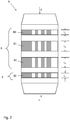
- the catalyst device 5 shown as an example has a denitrification catalyst 8 consisting of three layers 80, 81, 82 for reducing nitrogen oxides, namely a first layer 80, a second layer 81 and a third layer 82.
- the denitrification catalyst 8 is an oxidation catalyst in the flow direction of the exhaust gases 4 9 with only a first layer 90 connected downstream.
- the exhaust gases 4 flow through the catalytic converter device 5 from top to bottom.
- a reverse flow direction or a horizontal arrangement is also conceivable.
- the exhaust gases come out at the upper end of the preheater 1, so that a flow through the Offers catalyst device from top to bottom in order not to further increase the construction costs of the system.
- the first layer 80 of the denitrification catalyst 8 is L 1 and is shorter than the lengths L 2 , L 3 of the second and third layers 81, 82.
- the lengths L 2 , L 3 can be chosen to be of equal length, the length L 1 preferably being shorter than 70% of the length L 2 or L 3 .
- the first layer 80 of the denitrification catalytic converter 8 can in particular have a length L 1 which corresponds to the length of the inlet turbulence resulting from the exhaust gases 4 flowing through +/- 25%.
- the first layer 80 of the denitrification catalytic converter 8 thus rectifies and homogenizes the exhaust gases 4, so that the dust deposits and the associated problems in the subsequent layers 81, 82 of the denitrification catalytic converter 8 are also significantly reduced. With regard to the reduced length of the first layer 80 and the advantages associated therewith, reference is made explicitly to the DE 10 2010 060 104 B1 referenced.
- the first and only layer 90 of the oxidation catalyst 9 has a length L 4 which is less than the length L 3 directly upstream third layer 82 of the denitrification catalyst 8.
- the ratio L 4 / L 3 is preferably 0.8.
- the length L4 of the first layer 90 of the oxidation catalytic converter 9 is a maximum of 50% of the sum of the lengths L 1 , L 2 and L 3 .
- the cross-sectional area of the various layers of the denitrification catalytic converter 8 and of the oxidation catalytic converter 9 required for reducing pollutants depends primarily on the amount of exhaust gas 4 produced.
- Each layer of the two catalysts is made up of a large number of individual elements.
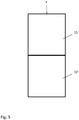
- Fig. 3 such an element 10 is shown.
- Each element 10 has a multiplicity of flow channels 11 which extend from an inflow end 12 to an outflow end 13 and through which the exhaust gas 4 flows.
- elements 10 with a cross section of 150 ⁇ 150 mm 2 are typically used, the elements 10 in the dust-laden exhaust gas typically from 10 ⁇ 10 to 19 ⁇ 19 flow channels exhibit. In principle, however, other dimensions (cross section and number of flow channels) would also be conceivable.
- Figure 4a shows, for example, the cross section through an element 10 of the first layer 80 of the denitrification catalytic converter 8, which provides 13 ⁇ 13 flow channels 11.
- Figures 4b, 4c and 4d each shows a section through the second layer 81, the third layer 82 of the denitrification catalyst 8 and the layer 90 of the oxidation catalyst 9, which each have 18 ⁇ 18 channels.
- the walls of the flow channels with which the exhaust gases 4 come into contact represent the surface effective for reducing the pollutants.
- the surface area that is effective for reducing the pollutants is also effective Surface area increased accordingly.
- the first layer 90 of the oxidation catalytic converter 9 has the same number of flow channels 11 per unit area as the second and third layers 81, 82 of the denitrification catalytic converter 8. According to a further embodiment of the invention, however, it can also be advantageous if the at least one first layer 90 of the oxidation catalytic converter 9 has a higher number of flow channels per unit area than each of the layers of the denitrification catalytic converter 8 the reduction effective area is increased accordingly, one must, however, accept an increased risk of clogging, which is due to the flow channels 11, which are becoming smaller and smaller in cross section. This risk of clogging would in turn have to be compensated for by a correspondingly higher output of the fan 7. It has therefore been found to be advantageous if there are no more than 18 x 18 flow channels in a unit of 150 x 150 mm.
- the element 10 can extend over the entire length of the respective layer of the catalytic converter, as shown in FIG Fig. 3 is shown.
- a layer is composed of two or more elements 10, 10 ′ stacked on top of one another, as in FIG Fig. 5 is shown schematically.
- a distance is expediently provided between the individual layers of the catalytic converter, which makes it possible to use a cleaning device 14 known per se ( Fig. 1 ), which is formed, for example, by a dust blower, in order to remove any dust deposits in the area of the inflowing ends 12 of the individual layers.
- the material used for the denitrification catalytic converter 8 or the oxidation catalytic converter 9 is often relatively soft, so that the cleaning device can damage the catalytic converters in the area of their inlet ends 12.
- Fig. 6 shows an embodiment in which the inflow end 12 of the element 10 is protected with a template 15, which only the front edges 16 (see Fig. 7 ) covers the flow channels 11 so that the exhaust gas 4 can flow in unhindered.
- the template 15 consists of a suitable wear protection material.
- Fig. 7 shows a plan view of an element 10 in the region of the inflow end 12 from which the front edges 16 can be seen.
- these front edges 16 are hardened in a suitable manner.
- a coating with monoaluminum phosphate is particularly suitable for this purpose.
- Fig. 8 shows an enlarged illustration of a flow channel 11 of the oxidation catalytic converter 9 extending from the inflow end 12 to the outflow end 13.
- the flow channels 11 are usually formed by a ceramic carrier material 91.
- a catalytically active component 92 in particular at least one noble metal, is applied to this carrier material 91, with no or only a (at least 50%) lower concentration of the catalytically active component 92 being applied in the area of the first 3 to 15 cm of the flow channels.
- additional protection of the inflow end 12 from the abrasive effect of the cleaning device 14 can also be provided.
- the dimensioning of a catalytic converter device 5 is shown below using an example: In a plant for the production of cement clinker, for example, 200,000 Nm3 / h of exhaust gases 4 can arise.
- the temperature of the exhaust gas 4 after the preheater can be 350 ° C. +/- 20 ° C., the exhaust gases 4 being drawn through the catalytic converter device 5 at a speed of approximately 3.5 m / s with the aid of the fan 7.
- the length L 1 of the first layer 80 of the denitrification catalyst 8 is, for example, 0.6 m and also has a volume of 22 m 3 .
- the second and third layers 81, 82 of the denitrification catalyst 8 are significantly larger with a length of 1.2 m and a volume of about 90 m 3.
- the first layer 90 of the oxidation catalytic converter 9 again has a length of 0.6 m and a volume of, for example, 22 m 3 .
Landscapes
- Engineering & Computer Science (AREA)
- Chemical & Material Sciences (AREA)
- Environmental & Geological Engineering (AREA)
- Health & Medical Sciences (AREA)
- Biomedical Technology (AREA)
- Analytical Chemistry (AREA)
- General Chemical & Material Sciences (AREA)
- Oil, Petroleum & Natural Gas (AREA)
- Chemical Kinetics & Catalysis (AREA)
- Ceramic Engineering (AREA)
- Biodiversity & Conservation Biology (AREA)
- Ecology (AREA)
- Environmental Sciences (AREA)
- Public Health (AREA)
- Life Sciences & Earth Sciences (AREA)
- Materials Engineering (AREA)
- Structural Engineering (AREA)
- Organic Chemistry (AREA)
- Exhaust Gas Treatment By Means Of Catalyst (AREA)
- Catalysts (AREA)
Description
- Die Erfindung betrifft eine Katalysatorvorrichtung zur Reduzierung von Schadstoffen in einem Abgas, insbesondere in einem Abgas von Industrieanlagen.
- Neben der Entstickung von Abgasen gewinnt die Minderung von Kohlenmonoxid (CO) und Kohlenwasserstoffen (THC) zunehmend Bedeutung. Die Minderung von Stickoxiden erfolgt u. a. mittels selektiver katalytischer Reduktion (SCR). An SCR-Katalysatoren findet dabei simultan zur Entstickung auch eine Minderung von THC statt. Die Reduzierung des CO-Gehalts ist aber nicht möglich, da hierfür spezielle Oxidationskatalysatoren erforderlich sind, die in der Regel teure Edelmetalle als aktive Komponenten aufweisen. Der Einsatz derartiger Katalysatoren ist daher mit hohen Kosten verbunden.
- Staubhaltige Abgase, wie sie beispielsweise in der Zementindustrie auftreten, haben eine Staubfracht im Bereich von 30 bis 150 mg/Nm3 und mehr. Zur katalytischen Minderung werden daher üblicherweise Wabenkatalysatoren eingesetzt, die ausreichend große Strömungsquerschnitte aufweisen, um Verstopfungen und Staubablagerung zu vermeiden.
- Aus der
DE 296 23 503 U1 ist eine Anlage zur Reinigung von Abgasen eines Zementdrehrohrofens mit Wärmetauscher bekannt, wobei unmittelbar nach dem Ofen eine Katalysatorvorrichtung angeordnet ist, welche drei katalytisch wirksame Lagen von modulartigem Aufbau umfasst. Zwei Lagen dienen dabei der Reduktion von NOx und Oxidation von Kohlenwasserstoffen, während die dritte Lage CO und Kohlenwasserstoffe oxidiert. - Auch die
EP 0 558 452 A1 offenbart die Kombination von mindestens einem Katalysator zur Reduktion von NOx mit einem nachgeschalteten Katalysator zur Oxidation von CO. - Der Erfindung liegt nun die Aufgabe zugrunde, eine Katalysatorvorrichtung anzugeben, die sich durch einen hohen Wirkungsgrad bei der Reduzierung von Stickoxiden, Kohlenwasserstoffen und Kohlenmonoxid bei vertretbaren Kosten auszeichnet.
- Erfindungsgemäß wird diese Aufgabe durch die Merkmale des Anspruches 1 gelöst.
- Die erfindungsgemäße Katalysatorvorrichtung zur Reduzierung von Schadstoffen in einem Abgas weist wenigstens eine Lage eines Entstickungskatalysators zur Minderung von Stickoxiden und wenigstens eine Lage eines dem Entstickungskatalysator nachgeschalteten Oxidationskatalysator zur Minderung von Kohlenmonoxid auf, wobei die wenigstens eine Lage des Entstickungskatalysators und die wenigstens eine Lage des nachgeschalteten Oxidationskatalysators jeweils eine Vielzahl von Strömungskanälen aufweisen. Die Länge der wenigstens einen Lage des Oxidationskatalysators ist dabei geringer als die Länge einer direkt vorgeschalteten Lage des Entstickungskatalysators und die wenigstens eine Lage des Oxidationskatalysators weist eine höhere Anzahl an Strömungskanälen als die erste Lage des Entstickungskatalysators auf.
- Durch die verkürzte Länge der wenigstens einen Lage des Oxidationskatalysators können die Kosten für den Oxidationskatalysator entsprechend verringert werden. Um dennoch einen ausreichend hohen Massentransfer (Oxidation des Kohlenmonoxids) zu gewährleisten, wird die Anzahl der Strömungskanäle (pro Einheit der Querschnittsfläche) des Oxidationskatalysators gegenüber der ersten Lage des Entstickungskatalysators erhöht. Durch eine höhere Anzahl der Strömungskanäle pro Querschnittsfläche, wird die für die Oxidation des Kohlenmonoxids wirksame Wandungsfläche der Strömungskanäle entsprechend erhöht. Mit anderen Worten weist die wenigstens eine Lage des nachgeschalteten Oxidationskatalysators eine höhere geometrische oder äußere Oberfläche als die erste Lage des Entstickungskatalysators auf.
- Gemäß einer bevorzugten Ausgestaltung der Erfindung wird der Entstickungskatalysator mit wenigstens zwei Lagen, vorzugsweise mit zwei bis fünf Lagen realisiert. Der Oxidationskatalysator besteht hingegen aus einer Lage, kann aber auch zwei bis drei Lagen aufweisen.
- Weiterhin kann die Länge der wenigstens einen Lage des Oxidationskatalysators so gewählt werden, dass sie maximal 80% der Länge der direkt vorgeschalteten Lage des Entstickungskatalysators entspricht. Weist der Entstickungskatalysator mehrere Lagen auf, beträgt die Länge aller Lagen des Oxidationskatalysators zweckmäßigerweise maximal 50% der Länge aller Lagen des Entstickungskatalysators.
- In einer weiteren Ausgestaltung der Erfindung ist die Anzahl der Strömungskanäle im Oxidationskatalysator um 25 bis 380% höher als die Anzahl der Strömungskanäle in der ersten Lage des Entstickungskatalysators. So kann die erste Lage beispielsweise aus Einheiten 150 x 150 mm mit 10 x 10 bis 13 x 13 Strömungskanälen aufgebaut sein, während die Lage des Oxidationskatalysators Einheiten von 150 x 150 mm mit 13 x 13 bis 19 x 19 Strömungskanälen vorsieht.
- Gemäß einer besonderen Ausgestaltung kann der Entstickungskatalysator wenigstens drei Lagen aufweisen, wobei die erste Lage des Entstickungskatalysator kürzer als die zweite Lage ausgebildet ist. Besonders vorteilhaft beträgt dabei das Verhältnis der kürzesten (ersten) Lage des Entstickungskatalysators zur längsten Lage des Entstickungskatalysators weniger als 0,7, höchstvorzugsweise weniger als 0,5. Eine derartige Ausgestaltung hat sich insbesondere bei Abgasen mit hohen Staubgehalten von mehr als 30 mg/Nm3 als vorteilhaft erwiesen. In diesem Zusammenhang wird explizit auf die
DE 10 2010 060 104 B4 verwiesen. So kann die Länge für die erste Lage des Entstickungskatalysators der Länge der sich aufgrund der durchströmenden Abgase ergebenen Einlaufturbulenz +/- 25% entsprechen. Durch die verkürzte erste Lage des Entstickungskatalysators wird eine homogenere Staub- und Strömungsverteilung erzeugt, die geringere Staubablagerungsspitzen und infolgedessen geringere Druckverluste in den nachfolgenden Lagen verursacht. - Gerade bei staubhaltigen Abgasen ist eine regelmäßige Abreinigung des Staubes im Bereich der Einströmenden der einzelnen Lagen zweckmäßig. Die einzelnen Lagen des Entstickungskatalysators und des Oxidationskatalysators sind daher zweckmäßigerweise voneinander beabstandet, wobei jede Lage ein Einströmende und ein Ausströmende aufweist und wenigstens eine Reinigungseinrichtung zum Entfernen von Staubablagerungen, beispielsweise ein Staubbläser, vorgesehen ist. Die Reinigungseinrichtung verwendet beispielsweise Druckluft, welche auf das Einströmende der Strömungskanäle gerichtet ist. Da das für die einzelnen Lagen der Katalysatoren verwendete Material aber vergleichsweise weich ist, kommt es dadurch zu einem erhöhten Verschleiß. Es kann daher zweckmäßig sein, wenn die Stirnkanten an den Einströmenden mittels einer Schablone abgeschirmt werden oder diese Stirnkanten gehärtet sind. Prinzipiell können bei einer Katalysatorvorrichtung auch verschiedene Maßnahmen (Härtung der Stirnkanten und Verwendung einer Schablone) zur Anwendung kommen. Es wäre beispielsweise denkbar, dass die Lagen des Entstickungskatalysators beispielsweise gehärtete Stirnkanten und die Lagen des Oxidationskatalysators eine Schablone aufweisen.
- Im Bereich des Oxidationskatalysators kann auch vorgesehen werden, dass die dort für die Kohlenstoffmonoxid-Oxidation aufgebrachte, katalytisch aktive Komponente im Bereich der ersten 3 bis 15 cm der Strömungskanäle entweder gar nicht vorhanden ist oder eine geringere Konzentration aufweist, um dadurch die teureren Kosten für die katalytisch aktive Komponente weiter zu senken, zumal die Effizienz des Oxidationskatalysators in seinem turbulenten Einlaufbereich deutlich reduziert wird, wenn ein erhöhter Verschleiß eintritt.
- Um einerseits eine hohe Effizienz bei der Entstickung und der Kohlenmonoxidminderung und andererseits vertretbare Kosten zu erreichen, ist es zweckmäßig, wenn das Volumen des Oxidationskatalysators lediglich zwischen 3 und 50%, vorzugsweise zwischen 5 und 30% des Volumens des Entstickungskatalysators beträgt. Das Volumen des Entstickungs- bzw. Oxidationskatalysators wird durch das vom Abgas durchströmbare Volumen aller Strömungskanäle definiert.
- Sowohl der Entstickungskatalysator als auch der Oxidationskatalysator umfassen an sich bekannte Katalysatormaterialien. So kann der Oxidationskatalysator insbesondere eine katalytisch aktive Komponente aufweisen, die wenigstens ein Edelmetall umfasst. Beim Entstickungskatalysator kommen insbesondere ein oder mehrere Komponenten, wie Titan, Wolfram und/oder Vanadium, in Betracht.
- Jede Lage des Entstickungskatalysators und des Oxidationskatalysators besteht quer zur Strömungsrichtung der Abgase aus mehreren nach Art einer Matrix angeordneten Elementen, die beispielsweise einen Querschnitt von 150 x 150 mm aufweisen. Insgesamt kann der Gesamtquerschnitt einer Lage 8 bis 30 m2 und mehr betragen. Die einzelnen Lagen können darüber hinaus jeweils eine Länge im Bereich von 0,5 bis 1,5 m aufweisen, wobei sich die einzelnen Elemente dabei jeweils über die gesamte Länge der jeweiligen Lage erstrecken oder sich aus mehreren, unmittelbar aneinander grenzenden Elementen zusammensetzen.
- Anhand der nachfolgenden Beschreibung und der Zeichnung werden weitere Ausgestaltungen der Erfindung näher beschrieben.
- In der Zeichnung zeigen
- Fig. 1
- eine schematische Darstellung der Katalysatorvorrichtung bei einer Zementklinkerherstellungsanlage,
- Fig. 2
- eine vergrößerte Darstellung der Katalysatorvorrichtung,
- Fig. 3
- eine schematische Längsschnittdarstellung durch eine Katalysatorlage,
- Fig. 4a-4d
- Querschnittsdarstellungen der verschiedenen Lagen der Katalysatorvorrichtung gemäß
Fig.2 , - Fig. 5
- eine schematische Seitenansicht einer Katalysatorlage mit übereinander gestapelten Elementen,
- Fig. 6
- eine schematische Darstellung eines Elements mit Schutz des Einströmendes durch eine Schablone
- Fig. 7
- Draufsicht eines Elements mit gehärteten Stirnkanten und
- Fig.8
- Längsschnittdarstcllung eines Strömungskanals mit partieller Aufbringung einer katalytisch aktiven Komponente.
-
Fig. 1 zeigt eine Anlage der Zementindustrie mit einem Vorwärmer 1 zum Vorwärmen von Zementrohmehl 2 und einen Ofen 3, insbesondere einen Drehrohrofen, zum Fertigbrennen des vorgewärmten Zementrohmehls. Selbstverständlich kann zwischen dem Vorwärmer 1 und dem Ofen 3 auch ein Calcinator zum Vorcalcinieren des vorgewärmten Zementrohmehls vorgesehen werden. - Die bei der Verbrennung im Ofen 3 und im ggf. vorhandenen Calcinator entstehenden Abgase durchströmen den Vorwärmer 1 und erwärmen dabei das Zementrohmehl 2. Die aus dem Vorwärmer 1 am oberen Ende austretenden Abgase 4 weisen beispielsweise einen Staubgehalt von 30 bis 150 mg/Nm3 und eine Temperatur von 250 bis 450 °C auf. Die Abgase 4 durchströmen im Folgenden eine Katalysatorvorrichtung 5 und werden dort in ihrem Schadstoffgehalt reduziert, wobei insbesondere eine Minderung von Stickoxiden und von Kohlenmonoxid stattfindet. Dabei entsteht ein im Schadstoffgehalt reduziertes Abgas 6, welches einer weiteren Schadstoffreinigung unterzogen, einer weiteren Behandlung (z.B. Kühlung) zugeführt, oder alternativ gleich in die Atmosphäre abgeleitet oder anderweitig verwendet werden kann. Der Gastransport durch die gesamte Anlage wird mit Hilfe eines der Katalysatorvorrichtung 5 nachgeschalteten Ventilator 7 bewirkt.
- Die in
Fig. 2 beispielshaft dargestellte Katalysatorvorrichtung 5 weist einen aus drei Lagen 80, 81, 82 bestehenden Entstickungskatalysator 8 zur Minderung von Stickoxiden auf, nämlich eine erste Lage 80, eine zweite Lage 81 und eine dritte Lage 82. Dem Entstickungskatalysator 8 ist in Strömungsrichtung der Abgase 4 ein Oxidationskatalysator 9 mit lediglich einer ersten Lage 90 nachgeschaltet. - Die Katalysatorvorrichtung 5 wird im dargestellten Ausführungsbeispiel von den Abgasen 4 von oben nach unten durchströmt. Prinzipiell ist aber auch eine umgekehrte Strömungsrichtung oder eine horizontale Anordnung denkbar. Bei einer Anlage zur Herstellung von Zementklinker kommen die Abgase jedoch am oberen Ende des Vorwärmers 1 heraus, sodass sich eine Durchströmung der Katalysatorvorrichtung von oben nach unten anbietet, um den Bauaufwand der Anlage nicht weiter zu erhöhen.
- Die erste Lage 80 des Entstickungskatalysators 8 beträgt L1 und ist kürzer als die Längen L2, L3 der zweiten und dritten Lage 81, 82 ausgebildet. Die Längen L2, L3 können dabei gleich lang gewählt werden, wobei die Länge L1 vorzugsweise kürzer als 70% der Länge L2 bzw. L3 ist. Die erste Lage 80 des Entstickungskatalysators 8 kann insbesondere eine Länge L1 aufweisen, die der Länge der sich aufgrund der durchströmenden Abgase 4 ergebenden Einlaufturbulenz +/- 25% entspricht. Durch die erste Lage 80 des Entstickungskatalysators 8 erfolgt somit eine Gleichrichtung und Homogenisierung der Abgase 4, sodass sich auch die Staubablagerungen und die damit einhergehenden Probleme bei den nachfolgenden Lagen 81, 82 des Entstickungskatalysators 8 deutlich reduzieren. Bezüglich der reduzierten Länge der ersten Lage 80 und den damit verbundenen Vorteilen wird explizit auf die
DE 10 2010 060 104 B1 verwiesen. - Die erste und einzige Lage 90 des Oxidationskatalysators 9 weist eine Länge L4 auf, die geringer ist als die Länge L3 direkt vorgeschaltete dritte Lage 82 des Entstickungskatalysators 8. Vorzugsweise beträgt das Verhältnis L4/L3 ≤ 0,8. Des Weiteren ist es vorteilhaft, wenn die Länge L4 der ersten Lage 90 des Oxidationskatalysators 9 maximal 50% der Summe der Länge L1, L2 und L3 beträgt.
- Die für die Schadstoffminderung erforderliche Querschnittsfläche der verschiedenen Lagen des Entstickungskatalysators 8 und des Oxidationskatalysators 9 hängt primär von der Menge des anfallenden Abgases 4 ab. Jede Lage der beiden Katalysatoren setzt sich jeweils aus einer Vielzahl von einzelnen Elementen zusammen. In
Fig. 3 ist ein solches Element 10 dargestellt. Jedes Element 10 weist eine Vielzahl von Strömungskanälen 11 auf, die sich von einem Einströmende 12 zu einem Ausströmende 13 erstrecken und vom Abgas 4 durchströmt werden. Bei den staubhaltigen Abgasen der Zementindustrie kommen typischerweise Elemente 10 mit einem Querschnitt von 150 x 150 mm2 zur Anwendung, wobei die Elemente 10 im staubbeladenen Abgas typischerweise 10 x 10 bis 19 x 19 Strömungskanäle aufweisen. Prinzipiell wären aber auch andere Dimensionierungen (Querschnitt und Anzahl der Strömungskanäle) denkbar. -
Fig. 4a stellt beispielsweise den Querschnitt durch ein Element 10 der ersten Lage 80 des Entstickungskatalysators 8 dar, das 13 x 13 Strömungskanäle 11 vorsieht. In denFig. 4b, 4c und 4d ist jeweils ein Schnitt durch die zweite Lage 81, die dritte Lage 82 des Entstickungskatalysators 8 und die Lage 90 des Oxidationskatalysators 9 dargestellt, die jeweils 18 x 18 Kanäle aufweisen. Die Wandungen der Strömungskanäle, mit denen die Abgase 4 in Kontakt kommen, stellen die für die Reduktion der Schadstoffe wirksame Oberfläche dar. Bei einer Einheit 10 mit einer größeren Anzahl an Strömungskanälen (bei gleichem Querschnitt) ist somit auch die für die Reduktion der Schadstoffe wirksame Oberfläche entsprechend erhöht. - Im Ausführungsbeispiel gemäß den
Fig. 4a - 4d weist die erste Lage 90 des Oxidationskatalysators 9 die gleiche Anzahl an Strömungskanälen 11 pro Flächeneinheit wie die zweite und dritte Lage 81, 82 des Entstickungskatalysators 8 auf. Gemäß einer weiteren Ausgestaltung der Erfindung kann es jedoch auch vorteilhaft sein, wenn die wenigstens eine erste Lage 90 des Oxidationskatalysators 9 eine höhere Anzahl an Strömungskanälen pro Flächeneinheit aufweist als jede der Lagen des Entstickungskatalysators 8. Wenngleich durch die Erhöhung der Anzahl der Strömungskanäle auch die für die Reduktion wirksame Fläche entsprechend vergrößert wird, muss man jedoch eine erhöhte Verstopfungsgefahr in Kauf nehmen, die durch die im Querschnitt immer kleiner werdenden Strömungskanäle 11 bedingt ist. Diese Verstopfungsgefahr müsste wiederum durch eine entsprechende höhere Leistung des Ventilators 7 ausgeglichen werden. Es hat sich daher als vorteilhaft herausgestellt, wenn bei einer Einheit von 150 x 150 mm nicht mehr als 18 x 18 Strömungskanäle vorhanden sind. - Prinzipiell kann sich das Element 10 über die gesamte Länge der jeweiligen Lage des Katalysators erstrecken, wie dies in
Fig. 3 dargestellt ist. Es ist aber auch durchaus denkbar, dass sich eine Lage jeweils aus zwei oder mehr übereinander gestapelten Elementen 10, 10' zusammensetzt, wie inFig. 5 schematisch dargestellt ist. Zwischen den einzelnen Lagen des Katalysators ist zweckmäßigerweise ein Abstand vorgesehen, der die Verwendung einer an sich bekannten Reinigungsvorrichtung 14 (Fig. 1 ) ermöglicht, die beispielsweise durch einen Staubbläser gebildet wird, um etwaige Staubablagerungen im Bereich der Einströmenden 12 der einzelnen Lagen zu entfernen. Das für den Entstickungskatalysator 8 bzw. den Oxidationskatalysator 9 verwendeten Material ist oftmals relativ weich, sodass es durch die Reinigungsvorrichtung zur Beschädigungen der Katalysatoren im Bereich ihrer Einströmenden 12 kommen kann. -
Fig. 6 zeigt ein Ausführungsbeispiel, bei dem das Einströmende 12 des Elements 10 mit einer Schablone 15 geschützt ist, welche lediglich die Stirnkanten 16 (sieheFig. 7 ) der Strömungskanäle 11 abdeckt, sodass das Abgas 4 ungehindert einströmen kann. Die Schablone 15 besteht aus einem geeigneten Verschleißschutzmaterial. -
Fig. 7 zeigt eine Draufsicht auf ein Element 10 im Bereich des Einströmendes 12 aus der die Stirnkanten 16 ersichtlich sind. Alternativ zu einer dieser Stirnkanten 16 abdeckenden Schablone 15 (Fig. 6 ) wäre es auch denkbar, dass diese Stirnkanten 16 in geeigneter Weise gehärtet werden. Hierfür bieten sich insbesondere eine Beschichtung mit Monoaluminiumphosphat an. -
Fig. 8 zeigt eine vergrößerte Darstellung eines sich vom Einströmende 12 zum Ausströmende 13 erstreckenden Strömungskanals 11 des Oxidationskatalysators 9. Die Strömungskanäle 11 werden üblicherweise durch ein keramisches Trägermaterial 91 gebildet. Auf diesem Trägermaterial 91 ist eine katalytisch aktive Komponente 92, insbesondere wenigstens ein Edelmetall, aufgebracht, wobei im Bereich der ersten 3 bis 15 cm der Strömungskanäle noch keine oder nur eine (um wenigstens 50%) geringere Konzentration der katalytisch aktiven Komponente 92 aufgebracht wird. Je nach Art des Trägermaterials 91 kann hierbei auch ein zusätzlicher Schutz des Einströmendes 12 vor der abrasiven Wirkung der Reinigungsvorrichtung 14 vorgesehen werden. - Nachfolgend wird anhand eine Beispiels die Dimensionierung einer Katalysatorvorrichtung 5 aufgezeigt: Bei einer Anlage zur Herstellung von Zementklinker können beispielsweise 200.000 Nm3/h an Abgasen 4 anfallen. Die Temperatur des Abgases 4 nach dem Vorwärmer kann dabei 350°C +/-20°C betragen, wobei die Abgase 4 mit einer Geschwindigkeit von etwa 3,5 m/s mit Hilfe des Ventilators 7 durch die Katalysatorvorrichtung 5 gezogen werden. Die Länge L1 der ersten Lage 80 des Entstickungskatalysators 8 beträgt beispielsweise 0,6 m und weist darüber hinaus ein Volumen von 22 m3 auf. Die zweite und dritte Lage 81, 82 des Entstickungskatalysators 8 sind mit einer Länge von 1,2 m und einem Volumen von etwa 90 m3 deutlich größer. Die erste Lage 90 des Oxidationskatalysators 9 weist wiederum eine Länge von 0,6 m und ein Volumen von beispielsweise 22 m3 auf.
Claims (14)
- Katalysatorvorrichtung (5) zur Reduzierung von Schadstoffen in einem Abgas (4) mit wenigstens einer Lage (80, 81, 82) eines Entstickungskatalysators (8) zur Minderung von Stickoxiden und wenigstens einer Lage (90) eines dem Entstickungskatalysator (8) nachgeschalteten Oxidationskatalysators (9) zur Minderung von Kohlenmonoxid, wobei die wenigstens eine Lage (80, 81, 82) des Entstickungskatalysators (8) und die wenigstens eine Lage (90) des nachgeschalteten Oxidationskatalysators (9) jeweils eine Vielzahl von Strömungskanälen (11) aufweist,
dadurch gekennzeichnet, dass die Länge (l4) der wenigstens einen Lage (90) des Oxidationskatalysators (9) geringer als die Länge (l3) einer direkt vorgeschalteten Lage (82) des Entstickungskatalysators (8) ist und die wenigstens eine Lage (90) des Oxidationskatalysators (9) eine höhere Anzahl an Strömungskanälen (11) als die erste Lage (80) des Entstickungskatalysators (8) aufweist. - Katalysatorvorrichtung nach Anspruch 1, dadurch gekennzeichnet, dass der Entstickungskatalysator (8) aus wenigstens zwei Lagen (80, 81, 82), vorzugsweise aus zwei bis fünf Lagen besteht.
- Katalysatorvorrichtung nach Anspruch 1, dadurch gekennzeichnet, dass der Oxidationskatalysator (9) aus wenigstens einer Lage (90), vorzugsweise aus ein bis drei Lagen besteht.
- Katalysatorvorrichtung nach Anspruch 1, dadurch gekennzeichnet, dass die Länge (L4) der wenigstens einen Lage (90) des Oxidationskatalysators (9) maximal 80% der Länge (L3) der direkt vorgeschalteten Lage (82) des Entstickungskatalysators (8) beträgt.
- Katalysatorvorrichtung nach Anspruch 1, dadurch gekennzeichnet, dass die Länge aller Lagen (90) des Oxidationskatalysators (9) maximal 50% der Länge aller Lagen (80, 81, 82) des Entstickungskatalysators (8) beträgt.
- Katalysatorvorrichtung nach Anspruch 1, dadurch gekennzeichnet, dass die Anzahl der Strömungskanäle (11) im Oxidationskatalysator (9) um 25 bis 380% höher als die Anzahl der Strömungskanäle in der ersten Lage (80) des Entstickungskatalysators (8) ist.
- Katalysatorvorrichtung nach Anspruch 1, dadurch gekennzeichnet, dass der Entstickungskatalysator (8) wenigstens drei Lagen (80, 81, 82) aufweist, wobei die erste Lage (80) des Entstickungskatalysator (8) kürzer als die zweite Lage (81) ausgebildet ist.
- Katalysatorvorrichtung nach Anspruch 1, dadurch gekennzeichnet, dass die Strömungskanäle (11) der wenigstens einen Lage (90) des Oxidationskatalysators (9) ein Einströmende (12) und ein Ausströmende (13) für das Abgas (4) aufweisen und für die Kohlenstoffmonoxid-Oxidation eine katalytisch aktive Komponente (92) aufweisen, wobei im Bereich der ersten 3 bis 15 cm der Strömungskanäle (11) im Bereich des Einströmendes (12) keine oder eine geringere Konzentration der katalytisch aktiven Komponente (92) vorgesehen ist.
- Katalysatorvorrichtung nach Anspruch 1, dadurch gekennzeichnet, dass die Strömungskanäle (11) der wenigstens einen Lage des Oxidationskatalysators (9) und/ oder des Entstickungskatalysators (8) ein Einströmende (12) und ein Ausströmende (13) für das Abgas (4) aufweisen, wobei die Strömungskanäle (11) am Einströmende (12) Stirnkanten (16) aufweisen, die gehärtet sind.
- Katalysatorvorrichtung nach Anspruch 1, dadurch gekennzeichnet, dass die Strömungskanäle (11) der wenigstens einen Lage des Oxidationskatalysators (9) und/ oder des Entstickungskatalysators (8) ein Einströmende (12) und ein Ausströmende (13) für das Abgas (4) aufweisen, wobei die Strömungskanäle (11) am Einströmende (12) Stirnkanten (16) aufweisen, die mittels einer Schablone (15) abgeschirmt sind.
- Katalysatorvorrichtung nach Anspruch 1, dadurch gekennzeichnet, dass der Oxidationskatalysator (9) eine katalytisch aktive Komponente (92) aufweist, die wenigstens ein Edelmetall umfasst.
- Katalysatorvorrichtung nach Anspruch 1, dadurch gekennzeichnet, dass der Entstickungskatalysator (8) insbesondere eine oder mehrere der nachfolgenden Komponenten, nämlich Titan, Wolfram und/oder Vanadium umfasst.
- Katalysatorvorrichtung nach Anspruch 1, dadurch gekennzeichnet, dass die einzelnen Lagen des Entstickungskatalysators (8) und des Oxidationskatalysators (9) voneinander beabstandet sind, wobei jede Lage ein Einströmende (12) und ein Ausströmende (13) aufweist und wenigstens eine Reinigungseinrichtung (14) zur Entfernung von Staubablagerungen im Bereich der Einströmenden (12) vorgesehen ist.
- Katalysatorvorrichtung nach Anspruch 1, dadurch gekennzeichnet, dass sich die Lagen des Entstickungskatalysators (8) und des Oxidationskatalysators (9) jeweils aus mehreren Elementen (10) zusammensetzen, die sich jeweils über die gesamte Länge der jeweiligen Lage erstrecken oder die aus mehreren, unmittelbar aneinandergrenzenden Elementen (10, 10') zusammengesetzt sind.
Applications Claiming Priority (2)
| Application Number | Priority Date | Filing Date | Title |
|---|---|---|---|
| DE102017119498.3A DE102017119498A1 (de) | 2017-08-25 | 2017-08-25 | Katalysatorvorrichtung zur Reduzierung von Schadstoffen in einem Abgas |
| PCT/EP2018/072095 WO2019038152A1 (de) | 2017-08-25 | 2018-08-15 | Katalysatorvorrichtung zur reduzierung von schadstoffen in einem abgas |
Publications (2)
| Publication Number | Publication Date |
|---|---|
| EP3672713A1 EP3672713A1 (de) | 2020-07-01 |
| EP3672713B1 true EP3672713B1 (de) | 2021-05-05 |
Family
ID=63254706
Family Applications (1)
| Application Number | Title | Priority Date | Filing Date |
|---|---|---|---|
| EP18756203.8A Active EP3672713B1 (de) | 2017-08-25 | 2018-08-15 | Katalysatorvorrichtung zur reduzierung von schadstoffen in einem abgas |
Country Status (3)
| Country | Link |
|---|---|
| EP (1) | EP3672713B1 (de) |
| DE (1) | DE102017119498A1 (de) |
| WO (1) | WO2019038152A1 (de) |
Cited By (1)
| Publication number | Priority date | Publication date | Assignee | Title |
|---|---|---|---|---|
| EP4684866A1 (de) | 2024-07-26 | 2026-01-28 | Scheuch Management Holding GmbH | Verfahren zur reinigung von gasförmige organische stoffe enthaltenden rauchgasen |
Family Cites Families (8)
| Publication number | Priority date | Publication date | Assignee | Title |
|---|---|---|---|---|
| DE10011327A1 (de) * | 2000-03-10 | 2001-09-27 | Gurudas Samant | Verfahren und Vorrichtung zur katalytischen Behandlung von Schwefel-und Stickoxide enthaltenden staub-und sauerstoffhaltigen Abgasen eines Zement-Drehrohrofens |
| DE3601378A1 (de) * | 1986-01-18 | 1987-07-23 | Degussa | Verfahren zur reinigung von oxide des stickstoffs und schwefels enthaltenden abgasen aus verbrennungsanlagen |
| CA2088713C (en) * | 1992-02-24 | 1999-11-16 | Hans Thomas Hug | Cleaning exhaust gases from combustion installations |
| DE4304323A1 (de) * | 1993-02-13 | 1994-08-18 | Huels Chemische Werke Ag | Katalysatorsystem zur Entfernung von NOx, CO und polychlorierten Dibenzodioxinen/Dibenzofuranen aus Abgasen sowie Verfahren zur Entfernung dieser Schadstoffe aus Abgasen |
| CH692181A5 (de) | 1995-09-08 | 2002-03-15 | Elex Ag | Rauchgasreinigungsanlage. |
| US20070189948A1 (en) * | 2006-02-14 | 2007-08-16 | Rocha Teresa G | Catalyst system and method |
| DE102010060104B4 (de) * | 2010-10-21 | 2014-02-06 | Elex Cemcat Ag | Rauchgasreinigungsstufe und Zementherstellungsanlage diese aufweisend |
| DE102015202698B4 (de) * | 2015-02-13 | 2020-11-05 | Maerz Ofenbau Ag | Verfahren zur Reinigung von Abgasen bei der thermischen Aufarbeitung von Mineralstoffen |
-
2017
- 2017-08-25 DE DE102017119498.3A patent/DE102017119498A1/de not_active Ceased
-
2018
- 2018-08-15 WO PCT/EP2018/072095 patent/WO2019038152A1/de not_active Ceased
- 2018-08-15 EP EP18756203.8A patent/EP3672713B1/de active Active
Cited By (2)
| Publication number | Priority date | Publication date | Assignee | Title |
|---|---|---|---|---|
| EP4684866A1 (de) | 2024-07-26 | 2026-01-28 | Scheuch Management Holding GmbH | Verfahren zur reinigung von gasförmige organische stoffe enthaltenden rauchgasen |
| WO2026021694A1 (de) | 2024-07-26 | 2026-01-29 | Scheuch Management Holding GmbH | Verfahren zur reinigung von gasförmige organische stoffe enthaltenden rauchgasen |
Also Published As
| Publication number | Publication date |
|---|---|
| WO2019038152A1 (de) | 2019-02-28 |
| DE102017119498A1 (de) | 2019-02-28 |
| EP3672713A1 (de) | 2020-07-01 |
Similar Documents
| Publication | Publication Date | Title |
|---|---|---|
| EP0482145B1 (de) | Katalysatoranordnung in einer kolonne | |
| EP2027372B1 (de) | Nebenstromfilter mit verbessertem filterwirkungsgrad | |
| DE69534984T2 (de) | Katalytische Einheit und Abgasreinigungsvorrichtung | |
| EP1189681B1 (de) | Reinigungseinrichtung für rauchgas | |
| DE102014005508A1 (de) | Verfahren und Anlage zur Entstickung von Rauchgasen mit SNCR (Selektive nichtkatalytische Reduktion) und nachgeschaltetem Katalysator zum Ammoniakabbau | |
| EP0152560B1 (de) | Matrix für einen katalytischen Reaktor zur Abgasreinigung | |
| DE3919343A1 (de) | Dieselrussfilter mit sich bei teillast verringerndem aktivem querschnitt | |
| DE3335917C2 (de) | Vorrichtung zum regenerativen Vorwärmen eines Verbrennungsluftstromes mit einem heißen NO↓x↓-haltigen Rauchgasstrom und zum Vermindern des in den Rauchgasen enthaltenen NO↓x↓ | |
| EP2444145B1 (de) | Rauchgasreinigungsanlage mit mehrlagigem scr-katalysator | |
| EP3325421B1 (de) | Verfahren und anlage zur herstellung von zementklinker oder anderen mineralischen produkten und zur entstickung von bypassgasen | |
| WO2012104111A1 (de) | Roststab | |
| EP3672713A1 (de) | Katalysatorvorrichtung zur reduzierung von schadstoffen in einem abgas | |
| DE102014106991B4 (de) | Vorrichtungen und Verfahren zur katalytischen Entstickung und regenerativen thermischen Nachverbrennung | |
| AT507105B1 (de) | Verfahren und vorrichtung zur reinigung von bei verbrennungsprozessen anfallenden abgasen | |
| WO2018073239A1 (de) | Verfahren und anlage zur reinigung von vorwärmerabgasen einer anlage der zement- und/oder mineralsindustrie | |
| EP2069615B1 (de) | Filterelement, insbesondere zur filterung von abgasen einer brennkraftmaschine | |
| DE4027329A1 (de) | Katalysator-anordnung zur stickoxidminderung in einem rauchgas | |
| DE19751788C2 (de) | Katalysatorkörper | |
| DE102015101356A1 (de) | Roststab mit Kühlmittel-Kanal | |
| DE8602600U1 (de) | Vorrichtung zur Halterung von Monolithkatalysatoren | |
| EP1559882B1 (de) | Abgasreinigungsanordnung und Verfahren zur Herstellung einer Abgasreinigungsanordnung | |
| WO2010136396A1 (de) | Verfahren und anlage zur wärmebehandlung von feinkörnigem material | |
| DE19635383A1 (de) | DeNOx-Katalysator für stark Staub-haltige Abgase | |
| EP1431528A2 (de) | Abgasreinigungsanordnung | |
| DE102006021737B4 (de) | Filterelement für einen Rußpartikelfilter einer Brennkraftmaschine |
Legal Events
| Date | Code | Title | Description |
|---|---|---|---|
| STAA | Information on the status of an ep patent application or granted ep patent |
Free format text: STATUS: UNKNOWN |
|
| STAA | Information on the status of an ep patent application or granted ep patent |
Free format text: STATUS: THE INTERNATIONAL PUBLICATION HAS BEEN MADE |
|
| PUAI | Public reference made under article 153(3) epc to a published international application that has entered the european phase |
Free format text: ORIGINAL CODE: 0009012 |
|
| STAA | Information on the status of an ep patent application or granted ep patent |
Free format text: STATUS: REQUEST FOR EXAMINATION WAS MADE |
|
| 17P | Request for examination filed |
Effective date: 20200325 |
|
| AK | Designated contracting states |
Kind code of ref document: A1 Designated state(s): AL AT BE BG CH CY CZ DE DK EE ES FI FR GB GR HR HU IE IS IT LI LT LU LV MC MK MT NL NO PL PT RO RS SE SI SK SM TR |
|
| AX | Request for extension of the european patent |
Extension state: BA ME |
|
| DAV | Request for validation of the european patent (deleted) | ||
| DAX | Request for extension of the european patent (deleted) | ||
| RIC1 | Information provided on ipc code assigned before grant |
Ipc: B01D 53/86 20060101AFI20201126BHEP Ipc: C04B 7/36 20060101ALI20201126BHEP |
|
| GRAP | Despatch of communication of intention to grant a patent |
Free format text: ORIGINAL CODE: EPIDOSNIGR1 |
|
| STAA | Information on the status of an ep patent application or granted ep patent |
Free format text: STATUS: GRANT OF PATENT IS INTENDED |
|
| INTG | Intention to grant announced |
Effective date: 20210114 |
|
| GRAS | Grant fee paid |
Free format text: ORIGINAL CODE: EPIDOSNIGR3 |
|
| GRAA | (expected) grant |
Free format text: ORIGINAL CODE: 0009210 |
|
| STAA | Information on the status of an ep patent application or granted ep patent |
Free format text: STATUS: THE PATENT HAS BEEN GRANTED |
|
| AK | Designated contracting states |
Kind code of ref document: B1 Designated state(s): AL AT BE BG CH CY CZ DE DK EE ES FI FR GB GR HR HU IE IS IT LI LT LU LV MC MK MT NL NO PL PT RO RS SE SI SK SM TR |
|
| REG | Reference to a national code |
Ref country code: GB Ref legal event code: FG4D Free format text: NOT ENGLISH |
|
| REG | Reference to a national code |
Ref country code: CH Ref legal event code: EP |
|
| REG | Reference to a national code |
Ref country code: AT Ref legal event code: REF Ref document number: 1389097 Country of ref document: AT Kind code of ref document: T Effective date: 20210515 |
|
| REG | Reference to a national code |
Ref country code: DE Ref legal event code: R096 Ref document number: 502018005182 Country of ref document: DE |
|
| REG | Reference to a national code |
Ref country code: IE Ref legal event code: FG4D Free format text: LANGUAGE OF EP DOCUMENT: GERMAN |
|
| REG | Reference to a national code |
Ref country code: LT Ref legal event code: MG9D |
|
| PG25 | Lapsed in a contracting state [announced via postgrant information from national office to epo] |
Ref country code: LT Free format text: LAPSE BECAUSE OF FAILURE TO SUBMIT A TRANSLATION OF THE DESCRIPTION OR TO PAY THE FEE WITHIN THE PRESCRIBED TIME-LIMIT Effective date: 20210505 Ref country code: HR Free format text: LAPSE BECAUSE OF FAILURE TO SUBMIT A TRANSLATION OF THE DESCRIPTION OR TO PAY THE FEE WITHIN THE PRESCRIBED TIME-LIMIT Effective date: 20210505 Ref country code: FI Free format text: LAPSE BECAUSE OF FAILURE TO SUBMIT A TRANSLATION OF THE DESCRIPTION OR TO PAY THE FEE WITHIN THE PRESCRIBED TIME-LIMIT Effective date: 20210505 Ref country code: BG Free format text: LAPSE BECAUSE OF FAILURE TO SUBMIT A TRANSLATION OF THE DESCRIPTION OR TO PAY THE FEE WITHIN THE PRESCRIBED TIME-LIMIT Effective date: 20210805 |
|
| PG25 | Lapsed in a contracting state [announced via postgrant information from national office to epo] |
Ref country code: PL Free format text: LAPSE BECAUSE OF FAILURE TO SUBMIT A TRANSLATION OF THE DESCRIPTION OR TO PAY THE FEE WITHIN THE PRESCRIBED TIME-LIMIT Effective date: 20210505 Ref country code: LV Free format text: LAPSE BECAUSE OF FAILURE TO SUBMIT A TRANSLATION OF THE DESCRIPTION OR TO PAY THE FEE WITHIN THE PRESCRIBED TIME-LIMIT Effective date: 20210505 Ref country code: NO Free format text: LAPSE BECAUSE OF FAILURE TO SUBMIT A TRANSLATION OF THE DESCRIPTION OR TO PAY THE FEE WITHIN THE PRESCRIBED TIME-LIMIT Effective date: 20210805 Ref country code: RS Free format text: LAPSE BECAUSE OF FAILURE TO SUBMIT A TRANSLATION OF THE DESCRIPTION OR TO PAY THE FEE WITHIN THE PRESCRIBED TIME-LIMIT Effective date: 20210505 Ref country code: SE Free format text: LAPSE BECAUSE OF FAILURE TO SUBMIT A TRANSLATION OF THE DESCRIPTION OR TO PAY THE FEE WITHIN THE PRESCRIBED TIME-LIMIT Effective date: 20210505 Ref country code: PT Free format text: LAPSE BECAUSE OF FAILURE TO SUBMIT A TRANSLATION OF THE DESCRIPTION OR TO PAY THE FEE WITHIN THE PRESCRIBED TIME-LIMIT Effective date: 20210906 Ref country code: GR Free format text: LAPSE BECAUSE OF FAILURE TO SUBMIT A TRANSLATION OF THE DESCRIPTION OR TO PAY THE FEE WITHIN THE PRESCRIBED TIME-LIMIT Effective date: 20210806 Ref country code: IS Free format text: LAPSE BECAUSE OF FAILURE TO SUBMIT A TRANSLATION OF THE DESCRIPTION OR TO PAY THE FEE WITHIN THE PRESCRIBED TIME-LIMIT Effective date: 20210905 |
|
| REG | Reference to a national code |
Ref country code: NL Ref legal event code: MP Effective date: 20210505 |
|
| PG25 | Lapsed in a contracting state [announced via postgrant information from national office to epo] |
Ref country code: NL Free format text: LAPSE BECAUSE OF FAILURE TO SUBMIT A TRANSLATION OF THE DESCRIPTION OR TO PAY THE FEE WITHIN THE PRESCRIBED TIME-LIMIT Effective date: 20210505 |
|
| PG25 | Lapsed in a contracting state [announced via postgrant information from national office to epo] |
Ref country code: SK Free format text: LAPSE BECAUSE OF FAILURE TO SUBMIT A TRANSLATION OF THE DESCRIPTION OR TO PAY THE FEE WITHIN THE PRESCRIBED TIME-LIMIT Effective date: 20210505 Ref country code: EE Free format text: LAPSE BECAUSE OF FAILURE TO SUBMIT A TRANSLATION OF THE DESCRIPTION OR TO PAY THE FEE WITHIN THE PRESCRIBED TIME-LIMIT Effective date: 20210505 Ref country code: ES Free format text: LAPSE BECAUSE OF FAILURE TO SUBMIT A TRANSLATION OF THE DESCRIPTION OR TO PAY THE FEE WITHIN THE PRESCRIBED TIME-LIMIT Effective date: 20210505 Ref country code: SM Free format text: LAPSE BECAUSE OF FAILURE TO SUBMIT A TRANSLATION OF THE DESCRIPTION OR TO PAY THE FEE WITHIN THE PRESCRIBED TIME-LIMIT Effective date: 20210505 Ref country code: RO Free format text: LAPSE BECAUSE OF FAILURE TO SUBMIT A TRANSLATION OF THE DESCRIPTION OR TO PAY THE FEE WITHIN THE PRESCRIBED TIME-LIMIT Effective date: 20210505 Ref country code: DK Free format text: LAPSE BECAUSE OF FAILURE TO SUBMIT A TRANSLATION OF THE DESCRIPTION OR TO PAY THE FEE WITHIN THE PRESCRIBED TIME-LIMIT Effective date: 20210505 Ref country code: CZ Free format text: LAPSE BECAUSE OF FAILURE TO SUBMIT A TRANSLATION OF THE DESCRIPTION OR TO PAY THE FEE WITHIN THE PRESCRIBED TIME-LIMIT Effective date: 20210505 |
|
| REG | Reference to a national code |
Ref country code: DE Ref legal event code: R097 Ref document number: 502018005182 Country of ref document: DE |
|
| PLBE | No opposition filed within time limit |
Free format text: ORIGINAL CODE: 0009261 |
|
| STAA | Information on the status of an ep patent application or granted ep patent |
Free format text: STATUS: NO OPPOSITION FILED WITHIN TIME LIMIT |
|
| REG | Reference to a national code |
Ref country code: CH Ref legal event code: PL |
|
| PG25 | Lapsed in a contracting state [announced via postgrant information from national office to epo] |
Ref country code: MC Free format text: LAPSE BECAUSE OF FAILURE TO SUBMIT A TRANSLATION OF THE DESCRIPTION OR TO PAY THE FEE WITHIN THE PRESCRIBED TIME-LIMIT Effective date: 20210505 |
|
| 26N | No opposition filed |
Effective date: 20220208 |
|
| REG | Reference to a national code |
Ref country code: BE Ref legal event code: MM Effective date: 20210831 |
|
| PG25 | Lapsed in a contracting state [announced via postgrant information from national office to epo] |
Ref country code: CH Free format text: LAPSE BECAUSE OF NON-PAYMENT OF DUE FEES Effective date: 20210831 Ref country code: LI Free format text: LAPSE BECAUSE OF NON-PAYMENT OF DUE FEES Effective date: 20210831 |
|
| PG25 | Lapsed in a contracting state [announced via postgrant information from national office to epo] |
Ref country code: IS Free format text: LAPSE BECAUSE OF FAILURE TO SUBMIT A TRANSLATION OF THE DESCRIPTION OR TO PAY THE FEE WITHIN THE PRESCRIBED TIME-LIMIT Effective date: 20210905 Ref country code: LU Free format text: LAPSE BECAUSE OF NON-PAYMENT OF DUE FEES Effective date: 20210815 Ref country code: AL Free format text: LAPSE BECAUSE OF FAILURE TO SUBMIT A TRANSLATION OF THE DESCRIPTION OR TO PAY THE FEE WITHIN THE PRESCRIBED TIME-LIMIT Effective date: 20210505 |
|
| PG25 | Lapsed in a contracting state [announced via postgrant information from national office to epo] |
Ref country code: IT Free format text: LAPSE BECAUSE OF FAILURE TO SUBMIT A TRANSLATION OF THE DESCRIPTION OR TO PAY THE FEE WITHIN THE PRESCRIBED TIME-LIMIT Effective date: 20210505 Ref country code: IE Free format text: LAPSE BECAUSE OF NON-PAYMENT OF DUE FEES Effective date: 20210815 Ref country code: FR Free format text: LAPSE BECAUSE OF NON-PAYMENT OF DUE FEES Effective date: 20210831 Ref country code: BE Free format text: LAPSE BECAUSE OF NON-PAYMENT OF DUE FEES Effective date: 20210831 |
|
| GBPC | Gb: european patent ceased through non-payment of renewal fee |
Effective date: 20220815 |
|
| PG25 | Lapsed in a contracting state [announced via postgrant information from national office to epo] |
Ref country code: CY Free format text: LAPSE BECAUSE OF FAILURE TO SUBMIT A TRANSLATION OF THE DESCRIPTION OR TO PAY THE FEE WITHIN THE PRESCRIBED TIME-LIMIT Effective date: 20210505 |
|
| PG25 | Lapsed in a contracting state [announced via postgrant information from national office to epo] |
Ref country code: HU Free format text: LAPSE BECAUSE OF FAILURE TO SUBMIT A TRANSLATION OF THE DESCRIPTION OR TO PAY THE FEE WITHIN THE PRESCRIBED TIME-LIMIT; INVALID AB INITIO Effective date: 20180815 |
|
| PG25 | Lapsed in a contracting state [announced via postgrant information from national office to epo] |
Ref country code: GB Free format text: LAPSE BECAUSE OF NON-PAYMENT OF DUE FEES Effective date: 20220815 |
|
| REG | Reference to a national code |
Ref country code: DE Ref legal event code: R081 Ref document number: 502018005182 Country of ref document: DE Owner name: THYSSENKRUPP POLYSIUS GMBH, DE Free format text: FORMER OWNERS: THYSSENKRUPP AG, 45143 ESSEN, DE; THYSSENKRUPP INDUSTRIAL SOLUTIONS AG, 45143 ESSEN, DE Ref country code: DE Ref legal event code: R081 Ref document number: 502018005182 Country of ref document: DE Owner name: THYSSENKRUPP AG, DE Free format text: FORMER OWNERS: THYSSENKRUPP AG, 45143 ESSEN, DE; THYSSENKRUPP INDUSTRIAL SOLUTIONS AG, 45143 ESSEN, DE |
|
| PG25 | Lapsed in a contracting state [announced via postgrant information from national office to epo] |
Ref country code: MK Free format text: LAPSE BECAUSE OF FAILURE TO SUBMIT A TRANSLATION OF THE DESCRIPTION OR TO PAY THE FEE WITHIN THE PRESCRIBED TIME-LIMIT Effective date: 20210505 |
|
| PG25 | Lapsed in a contracting state [announced via postgrant information from national office to epo] |
Ref country code: MT Free format text: LAPSE BECAUSE OF FAILURE TO SUBMIT A TRANSLATION OF THE DESCRIPTION OR TO PAY THE FEE WITHIN THE PRESCRIBED TIME-LIMIT Effective date: 20210505 |
|
| PGFP | Annual fee paid to national office [announced via postgrant information from national office to epo] |
Ref country code: DE Payment date: 20240821 Year of fee payment: 7 |
|
| REG | Reference to a national code |
Ref country code: AT Ref legal event code: MM01 Ref document number: 1389097 Country of ref document: AT Kind code of ref document: T Effective date: 20230815 |
|
| PG25 | Lapsed in a contracting state [announced via postgrant information from national office to epo] |
Ref country code: AT Free format text: LAPSE BECAUSE OF NON-PAYMENT OF DUE FEES Effective date: 20230815 |
|
| PG25 | Lapsed in a contracting state [announced via postgrant information from national office to epo] |
Ref country code: AT Free format text: LAPSE BECAUSE OF NON-PAYMENT OF DUE FEES Effective date: 20230815 |
|
| PG25 | Lapsed in a contracting state [announced via postgrant information from national office to epo] |
Ref country code: TR Free format text: LAPSE BECAUSE OF FAILURE TO SUBMIT A TRANSLATION OF THE DESCRIPTION OR TO PAY THE FEE WITHIN THE PRESCRIBED TIME-LIMIT Effective date: 20210505 |
|
| REG | Reference to a national code |
Ref country code: DE Ref legal event code: R119 Ref document number: 502018005182 Country of ref document: DE |
|
| PGFP | Annual fee paid to national office [announced via postgrant information from national office to epo] |
Ref country code: AT Payment date: 20260410 Year of fee payment: 5 |