EP3672538B1 - Implant delivery system - Google Patents
Implant delivery system Download PDFInfo
- Publication number
- EP3672538B1 EP3672538B1 EP18762997.7A EP18762997A EP3672538B1 EP 3672538 B1 EP3672538 B1 EP 3672538B1 EP 18762997 A EP18762997 A EP 18762997A EP 3672538 B1 EP3672538 B1 EP 3672538B1
- Authority
- EP
- European Patent Office
- Prior art keywords
- floating element
- implant
- engaging
- bumper
- delivery system
- Prior art date
- Legal status (The legal status is an assumption and is not a legal conclusion. Google has not performed a legal analysis and makes no representation as to the accuracy of the status listed.)
- Active
Links
- 239000007943 implant Substances 0.000 title claims description 123
- 239000000463 material Substances 0.000 description 24
- 210000005166 vasculature Anatomy 0.000 description 9
- 229910001000 nickel titanium Inorganic materials 0.000 description 8
- 229920000642 polymer Polymers 0.000 description 8
- 239000010935 stainless steel Substances 0.000 description 8
- -1 polyethylene Polymers 0.000 description 7
- 229910001220 stainless steel Inorganic materials 0.000 description 7
- 229910052751 metal Inorganic materials 0.000 description 6
- 239000002184 metal Substances 0.000 description 6
- 150000002739 metals Chemical class 0.000 description 6
- 238000000034 method Methods 0.000 description 5
- PXHVJJICTQNCMI-UHFFFAOYSA-N Nickel Chemical compound [Ni] PXHVJJICTQNCMI-UHFFFAOYSA-N 0.000 description 4
- 230000008901 benefit Effects 0.000 description 4
- 239000002131 composite material Substances 0.000 description 4
- 229910001092 metal group alloy Inorganic materials 0.000 description 4
- HLXZNVUGXRDIFK-UHFFFAOYSA-N nickel titanium Chemical compound [Ti].[Ti].[Ti].[Ti].[Ti].[Ti].[Ti].[Ti].[Ti].[Ti].[Ti].[Ni].[Ni].[Ni].[Ni].[Ni].[Ni].[Ni].[Ni].[Ni].[Ni].[Ni].[Ni].[Ni].[Ni] HLXZNVUGXRDIFK-UHFFFAOYSA-N 0.000 description 4
- 238000013519 translation Methods 0.000 description 4
- 239000004698 Polyethylene Substances 0.000 description 3
- 239000004721 Polyphenylene oxide Substances 0.000 description 3
- 239000000560 biocompatible material Substances 0.000 description 3
- 210000004204 blood vessel Anatomy 0.000 description 3
- 239000012530 fluid Substances 0.000 description 3
- 230000006870 function Effects 0.000 description 3
- 229920000573 polyethylene Polymers 0.000 description 3
- 230000002792 vascular Effects 0.000 description 3
- 239000004812 Fluorinated ethylene propylene Substances 0.000 description 2
- 229930040373 Paraformaldehyde Natural products 0.000 description 2
- 239000004696 Poly ether ether ketone Substances 0.000 description 2
- 229920002614 Polyether block amide Polymers 0.000 description 2
- 239000004734 Polyphenylene sulfide Substances 0.000 description 2
- 239000004743 Polypropylene Substances 0.000 description 2
- RTAQQCXQSZGOHL-UHFFFAOYSA-N Titanium Chemical compound [Ti] RTAQQCXQSZGOHL-UHFFFAOYSA-N 0.000 description 2
- 229910045601 alloy Inorganic materials 0.000 description 2
- 239000000956 alloy Substances 0.000 description 2
- 238000013461 design Methods 0.000 description 2
- 238000006073 displacement reaction Methods 0.000 description 2
- 229910000701 elgiloys (Co-Cr-Ni Alloy) Inorganic materials 0.000 description 2
- 238000005530 etching Methods 0.000 description 2
- 230000001788 irregular Effects 0.000 description 2
- 239000000203 mixture Substances 0.000 description 2
- 229910052759 nickel Inorganic materials 0.000 description 2
- 229920009441 perflouroethylene propylene Polymers 0.000 description 2
- 229920001707 polybutylene terephthalate Polymers 0.000 description 2
- 229920002530 polyetherether ketone Polymers 0.000 description 2
- 229920006324 polyoxymethylene Polymers 0.000 description 2
- 229920006380 polyphenylene oxide Polymers 0.000 description 2
- 229920000069 polyphenylene sulfide Polymers 0.000 description 2
- 229920001155 polypropylene Polymers 0.000 description 2
- 239000004810 polytetrafluoroethylene Substances 0.000 description 2
- 229920001343 polytetrafluoroethylene Polymers 0.000 description 2
- 229920000431 shape-memory polymer Polymers 0.000 description 2
- 239000011343 solid material Substances 0.000 description 2
- 239000010936 titanium Substances 0.000 description 2
- 229910052719 titanium Inorganic materials 0.000 description 2
- KHXKESCWFMPTFT-UHFFFAOYSA-N 1,1,1,2,2,3,3-heptafluoro-3-(1,2,2-trifluoroethenoxy)propane Chemical compound FC(F)=C(F)OC(F)(F)C(F)(F)C(F)(F)F KHXKESCWFMPTFT-UHFFFAOYSA-N 0.000 description 1
- 206010002329 Aneurysm Diseases 0.000 description 1
- 229910001020 Au alloy Inorganic materials 0.000 description 1
- 229910000531 Co alloy Inorganic materials 0.000 description 1
- 229910000640 Fe alloy Inorganic materials 0.000 description 1
- 239000004677 Nylon Substances 0.000 description 1
- 239000004952 Polyamide Substances 0.000 description 1
- 239000004642 Polyimide Substances 0.000 description 1
- 229910001362 Ta alloys Inorganic materials 0.000 description 1
- 229910001080 W alloy Inorganic materials 0.000 description 1
- 238000013459 approach Methods 0.000 description 1
- 239000008280 blood Substances 0.000 description 1
- 210000004369 blood Anatomy 0.000 description 1
- 230000017531 blood circulation Effects 0.000 description 1
- 230000002490 cerebral effect Effects 0.000 description 1
- BIJOYKCOMBZXAE-UHFFFAOYSA-N chromium iron nickel Chemical compound [Cr].[Fe].[Ni] BIJOYKCOMBZXAE-UHFFFAOYSA-N 0.000 description 1
- 238000004891 communication Methods 0.000 description 1
- 230000001419 dependent effect Effects 0.000 description 1
- 238000011161 development Methods 0.000 description 1
- 230000018109 developmental process Effects 0.000 description 1
- 238000010586 diagram Methods 0.000 description 1
- 150000002148 esters Chemical class 0.000 description 1
- HQQADJVZYDDRJT-UHFFFAOYSA-N ethene;prop-1-ene Chemical group C=C.CC=C HQQADJVZYDDRJT-UHFFFAOYSA-N 0.000 description 1
- PCHJSUWPFVWCPO-UHFFFAOYSA-N gold Chemical compound [Au] PCHJSUWPFVWCPO-UHFFFAOYSA-N 0.000 description 1
- 239000010931 gold Substances 0.000 description 1
- 229910052737 gold Inorganic materials 0.000 description 1
- 239000003353 gold alloy Substances 0.000 description 1
- 238000009998 heat setting Methods 0.000 description 1
- 239000002905 metal composite material Substances 0.000 description 1
- 238000012986 modification Methods 0.000 description 1
- 230000004048 modification Effects 0.000 description 1
- 229910000623 nickel–chromium alloy Inorganic materials 0.000 description 1
- 229920001778 nylon Polymers 0.000 description 1
- 230000002093 peripheral effect Effects 0.000 description 1
- 229920002647 polyamide Polymers 0.000 description 1
- 229920000570 polyether Polymers 0.000 description 1
- 229920001721 polyimide Polymers 0.000 description 1
- 229920002635 polyurethane Polymers 0.000 description 1
- 239000004814 polyurethane Substances 0.000 description 1
- 239000004800 polyvinyl chloride Substances 0.000 description 1
- 230000008569 process Effects 0.000 description 1
- 230000002787 reinforcement Effects 0.000 description 1
- 229910001285 shape-memory alloy Inorganic materials 0.000 description 1
- 229910001256 stainless steel alloy Inorganic materials 0.000 description 1
- 229910052715 tantalum Inorganic materials 0.000 description 1
- GUVRBAGPIYLISA-UHFFFAOYSA-N tantalum atom Chemical compound [Ta] GUVRBAGPIYLISA-UHFFFAOYSA-N 0.000 description 1
- 230000007704 transition Effects 0.000 description 1
- WFKWXMTUELFFGS-UHFFFAOYSA-N tungsten Chemical compound [W] WFKWXMTUELFFGS-UHFFFAOYSA-N 0.000 description 1
- 229910052721 tungsten Inorganic materials 0.000 description 1
- 239000010937 tungsten Substances 0.000 description 1
- 208000019553 vascular disease Diseases 0.000 description 1
- 238000012800 visualization Methods 0.000 description 1
Images


Classifications
-
- A—HUMAN NECESSITIES
- A61—MEDICAL OR VETERINARY SCIENCE; HYGIENE
- A61F—FILTERS IMPLANTABLE INTO BLOOD VESSELS; PROSTHESES; DEVICES PROVIDING PATENCY TO, OR PREVENTING COLLAPSING OF, TUBULAR STRUCTURES OF THE BODY, e.g. STENTS; ORTHOPAEDIC, NURSING OR CONTRACEPTIVE DEVICES; FOMENTATION; TREATMENT OR PROTECTION OF EYES OR EARS; BANDAGES, DRESSINGS OR ABSORBENT PADS; FIRST-AID KITS
- A61F2/00—Filters implantable into blood vessels; Prostheses, i.e. artificial substitutes or replacements for parts of the body; Appliances for connecting them with the body; Devices providing patency to, or preventing collapsing of, tubular structures of the body, e.g. stents
- A61F2/95—Instruments specially adapted for placement or removal of stents or stent-grafts
- A61F2/962—Instruments specially adapted for placement or removal of stents or stent-grafts having an outer sleeve
- A61F2/966—Instruments specially adapted for placement or removal of stents or stent-grafts having an outer sleeve with relative longitudinal movement between outer sleeve and prosthesis, e.g. using a push rod
- A61F2002/9665—Instruments specially adapted for placement or removal of stents or stent-grafts having an outer sleeve with relative longitudinal movement between outer sleeve and prosthesis, e.g. using a push rod with additional retaining means
Definitions
- the present disclosure relates generally to medical devices and, more particularly, to devices for delivering an implant to a target site in a blood or other body vessel.
- intravascular medical devices have become an effective method for treating many types of vascular disease.
- a suitable intravascular device is inserted into the vascular system of the patient and navigated through the vasculature to a desired target site.
- a target site in the patient's vascular system may be accessed, including the coronary, cerebral, and peripheral vasculature.
- Medical implants such as stents, stent grafts, flow-diverters, and vena cava filters, are often utilized in combination with a delivery device for placement at a desired location within the body.
- a medical implant such as a stent
- the stent Once delivered to a target location within the body, the stent may then be expanded to an enlarged configuration within the vessel to support and reinforce the vessel wall while maintaining the vessel in an open, unobstructed condition.
- the stent may be configured to be self-expanding, expanded by a stored potential radial force such as a balloon, or a combination of self-expanding and balloon expanded.
- an implant delivery system comprises an elongate tubular member having a lumen, a tubular implant coaxially disposed within the lumen of the elongate tubular member, and a delivery assembly having a distal portion coaxially disposed within tubular implant
- the delivery assembly comprises a delivery wire, an engaging bumper fixedly coupled to the delivery wire, a stopper bumper fixedly coupled to the delivery wire, and a floating element slidably coupled around the delivery wire and disposed between the bumpers
- the floating element has an engaging portion configured to engage the engaging bumper when the delivery wire is axially translated relative to the elongate member in a first direction, wherein the floating element is configured to radially expand (e.g., by flaring outward) to frictionally engage the implant when the engaging portion of the floating element engages the engaging bumper.
- the floating element comprises an annular portion slidably disposed around the delivery wire.
- the annular portion is configured to contact the stopper bumper when the delivery wire is axially translated relative to the elongate member in a second direction opposite to the first direction.
- the floating element is configured to maintain a radially unexpanded configuration in which the floating element does not frictionally engage the implant when the annular portion of the floating element contacts the stopper bumper.
- the engaging portion of the floating element has an inner surface
- the engaging bumper has an outer surface that engages the inner surface of the floating element when the delivery wire is axially translated relative to the elongate member in the first direction.
- the outer surface of the engaging bumper may taper inwards towards the engaging portion of the floating element.
- the annular portion of the floating element has an abutting surface and the stopper bumper has a corresponding abutting surface that abuts the abutting surface of the floating element when the delivery wire is axially translated relative to the elongate member in the second direction.
- the abutting surface of the stopper bumper may be substantially perpendicular to the second direction.
- the engaging portion of the floating element may have one of a funnel-like, flower-like, and skirt-like configuration.
- the engaging portion of the floating element may have a funnel-like configuration including an elastically compressible bent section disposed between two straight sections.
- the engaging portion of the floating element may have a flower-like configuration including a plurality of petal-like elements.
- the engaging portion of the floating element may have a flower-like configuration including a plurality of flaps.
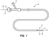
- the implant delivery system 10 generally comprises an elongate tubular member 12, a tubular implant 20 (not shown in FIG. 1 ), and a delivery assembly 30.
- the elongate member 12 has a tubular configuration, and can, e.g., take the form of a sheath, catheter, micro-catheter or the like.
- the elongate member 12 has a proximal portion 13, a distal portion 16, and a lumen 17 extending through the elongate member 12 between the proximal portion 13 and the distal portion 16.
- the proximal section 13 of the elongate member 12 remains outside of the patient and accessible to the operator when the implant delivery system 10 is in use, while the distal portion 16 of the elongate member 12 is sized and dimensioned to reach remote locations of a vasculature and is configured to deliver the implant 20 to a target location in a patient's body, such as an occlusion in a blood vessel, in a blood vessel adjacent to an aneurysm neck, a bifurcated blood vessel, or the like.
- the implant delivery system 10 has at least one fluid port 15 in fluid communication with the elongate member 12, which is used to introduce fluids into the elongate member 12.
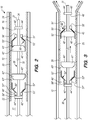
- the implant 20 and delivery assembly 30 are disposed in the lumen 17 of the elongate member 12 of the implant delivery system 10, as better appreciated in FIG. 2 .
- the implant 20 such a stent or a flow diverter, includes a tubular resilient member having a proximal portion 22, a distal portion 24, and defining an inner lumen 26 extending therebetween ( FIG. 2 ).
- the implant 20 has a delivery configuration when disposed within the lumen 17 of the elongate member 12 and/or is radially constrained by the elongate member 12.
- the implant 20 is biased to expand radially outwards into a deployed configuration in which the implant 20 is expanded when deployed out of the elongate member 12.
- the implant 20 may be constructed from a variety of materials such as stainless steel, elgiloy, nickel, titanium, nitinol, shape memory polymers, or combinations thereof.
- the implant 20 may also be formed in a variety of manners as well.
- the implant 20 may be formed by etching or cutting a pattern from a tube or sheet of stent material; a sheet of stent material may be cut or etched according to a desired stent pattern whereupon the sheet may be rolled or otherwise formed into the desired substantially tubular, bifurcated or other shape.
- one or more wires or ribbons of stent material may be woven, braided or otherwise formed into a desired shape and pattern.
- the implant 20 may include further components that are welded, bonded or otherwise engaged to one another.
- the implant 20 may include a non-porous, non-permeable biocompatible material, cover or the like, when the implant 20 is used as a blood flow diverter.
- the implant delivery system 10 may be used in an "over-the-wire” configuration, wherein the elongate member 12 is introduced into the patient over a guidewire which has been previously introduced, and the elongate member 12 extends over the entire length of the guidewire (not shown).
- the implant delivery system 10 may be used in a "rapid-exchange" configuration, where a guidewire extends through only a distal portion of the implant delivery system 10 from a guidewire port (not shown).
- the implant delivery system 10 may be introduced into the patient after a guidewire had been withdrawn leaving a sheath or access catheter distal portion at the target site for the assembly 10 to navigate through the vasculature of the patient within the sheath or access catheter.
- the implant delivery system 10 may include one or more, or a plurality of regions along its length having different configurations and/or characteristics.
- the distal portion 16 of the elongate member 12 may have an outer diameter less than the outer diameter of the proximal portion 13 to reduce the profile of the distal portion 16 and facilitate navigation in tortuous vasculature ( FIG. 1 ).
- the distal portion 16 may be more flexible than the proximal portion 13.
- the proximal portion 13 may be formed from material that is stiffer than the distal portion 16 of the elongate member 12, so that the proximal portion 13 has sufficient pushability to advance through the patient's vascular system, while the distal portion 16 may be formed of a more flexible material so that the distal portion 16 may remain flexible and track more easily over a guidewire to access remote locations in tortuous regions of the vasculature.
- the elongate member 12 may be composed of suitable polymeric materials, metals and/or alloys, such as polyethylene, stainless steel or other suitable biocompatible materials or combinations thereof.
- the proximal portion 13 may include a reinforcement layer, such a braided layer or coiled layer to enhance the pushability of the elongate member 12.
- the elongate member 12 may include a transition region between the proximal portion 13 and the distal portion 16.
- the implant 20 is coaxially disposed within the distal portion 16 of elongate member 12, and the delivery assembly 30 is coaxially disposed and axially movable relative to the elongate member 12 and the implant 20.
- the delivery assembly 30 is configured to engage the implant 20 when the system 30 is axially translated relative to the elongate member 12 for delivery of the implant 20 into a target site of a patient.
- the interface between the delivery assembly 30 and the implant 20 will be described in further detail below.
- the delivery assembly 30 comprises a delivery wire 31 having a proximal region 32 and a distal region 33 ( FIG. 1 ).
- the delivery wire 31 may be made of a conventional guidewire, torqueable cable tube, a hypotube or the like. In either case, there are numerous materials that can be used for the delivery wire 31 to achieve the desired properties that are commonly associated with medical devices. Some examples can include metals, metal alloys, polymers, metal-polymer composites, and the like, or any other suitable material.
- the delivery wire 31 may include nickel-titanium alloy, stainless steel, a composite of nickel-titanium alloy and stainless steel. In some cases, the delivery wire 31 can be made of the same material along its length, or in some embodiments, can include portions or sections made of different materials.
- the material used to construct the delivery wire 31 is chosen to impart varying flexibility and stiffness characteristics to different portions of the delivery wire 31.
- the proximal region and the distal region 33 of the delivery wire 31 may be formed of different materials, such as materials having different moduli of elasticity, resulting in a difference in flexibility.
- the proximal region 32 can be formed of stainless steel, and the distal region 33 can be formed of a nickel-titanium alloy.
- any suitable material or combination of material may be used for the delivery wire 31, as desired.
- the delivery wire 31 may further include a distal shapeable or pre-shaped atraumatic end 34 ( FIG. 2 ), which may aid the advancement of the delivery wire 31.
- the distal end 34 may include a coil placed over a portion of a distal end of the delivery wire 31 (not shown) or, alternatively, may include a material melted down and placed over a portion of the distal end 34 of the delivery wire 31.
- the distal end 34 may include a radiopaque material to aid in visualization.
- the distal end 34 of the delivery wire 31 may be floppy and steerable using pull wires (not shown) to facilitate tracking of the delivery assembly 30 through a vessel to reach a target site.
- the distal end 34 of the delivery wire 31 may include one or more tapered sections, as desired.
- the delivery wire 31 may optionally include one or more bands (not shown) in the distal region 33 of the delivery wire 31.
- the bands may be formed integrally into the delivery wire 31, or they may be separately formed from the delivery wire 31 and attached thereto. In some embodiments, the bands may be disposed on the delivery wire 31.
- the bands may have a diameter greater than the diameter of the surrounding the delivery wire 31.
- Bands may be formed of any suitable material, such as metals, metal alloys, polymers, metal-polymer composites, and the like, or any other suitable material, as well as any radiopaque material, as desired.
- the delivery wire 31 may include one or more recesses instead of providing bands, if desired.
- the delivery assembly 30 comprises at least one set of bumpers 40 fixedly coupled to the delivery wire 31, and a floating element 50 slidably coupled to the delivery wire 31.
- two sets of bumpers 40 (a first set of distal bumpers 40' and a second set of proximal bumpers 40") are disposed at the distal portion 32 of the delivery wire 31, with each set having a respective floating element 50'/50" therebetween.
- the distal bumpers 40' include a distal engaging bumper 42' and a distal stopper bumper 44', with a distal floating element 50' therebetween
- the proximal bumpers 40" include a proximal engaging bumper 42" and a proximal stopper bumper 44", with a proximal floating element 50" therebetween.
- the engaging bumpers 42/42'/42" and the stopper bumpers 44/44'/44" are configured to limit translation of the respective floating elements 50/50'/50" therebetween.
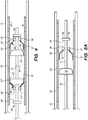
- the engaging bumpers 42/42'/42" are configured to interface with the respective floating elements 50/50'/50" to engage (i.e., frictionally engage) the implant 20 for delivery to a target site ( FIGS. 3 , 5A-D ) and/or re-sheathing the implant 20 into the elongate member 12 ( FIG. 4 ) .
- Each floating element 50/50'/50 has an annular portion 51/51'/51", such as a collar, ring or the like, and engaging portion 52/52'/52" having an inner surface 53/53'/53” configured to interface with an outer surface 43/43'/43" of the engaging bumper 42/42'/42" when the delivery assembly 30 is actuated, which is described in further detail below.
- the engaging portion 52' of the distal floating element 50' is proximately disposed to the annular portion 51' of the distal floating element 50', such that the interface between the distal engaging bumper 42' and engaging portion 52' of the distal floating element 50' is configured to engage the implant 20 when the delivery wire 31 is advanced or translated in the distal direction for delivery of the implant 20 into the target site of the patient ( FIG. 3 ).
- the engaging portion 52" of the proximal floating element 50" is distally disposed to the annular portion 51 of the proximal floating element 50", such that the interface between the proximal engaging bumper 42" and engaging portion 52" of the proximal floating element 50" is configured to engage the implant 20 when the delivery wire 31 is withdrawn or translated in the proximal direction for re-sheathing of the implant 20 into the elongate member 12 ( FIG. 4 ).
- the delivery assembly 30 is actuated by advancing (i.e., distally translating, axially moving) the delivery wire 31 relative to the elongate member 12.
- the distal engaging bumper 42' interfaces with the engaging portion 52' of the distal floating element 50', wherein the outer surface 43' of the engaging bumper 42' contacts the inner surface 53' of the engaging portion 52', so that the engaging portion 52' of the distal floating element 50' is disposed between the distal engaging bumper 42' and the implant 20.
- the interface between the distal engaging bumper 42' and the engaging portion 52' of the distal floating element 50' exerts a radially outward force on an interior surface 25 of the implant 20.
- This radially outward force is sufficient to contact and frictionally engage the implant 20 so as to advance and deliver the implant 20 to a target site when the delivery wire 31 advances relative to the elongate member 12. Furthermore, when the delivery wire 31 is advanced relative to the elongate member 12, the proximal stopper bumper 44" contacts the annular portion 51" of the proximal floating element 50", advancing and distally pushing the proximal floating element 50" along with the advancement of the delivery wire 31. As shown in FIG. 3 , the proximal floating element 50" does not frictionally engage the implant 20 during advancement of the delivery wire 31.
- the delivery assembly 30 is actuated by withdrawing (i.e., proximately translating, axially moving) the delivery wire 31 relative to the elongate member 12.
- withdrawing i.e., proximately translating, axially moving
- the proximal engaging bumper 42" interfaces with the engaging portion 52" of the proximal floating element 50", wherein the outer surface 43 of the engaging bumper 42” contacts the inner surface 53" of the engaging portion 52", so that the engaging portion 52" of the proximal floating element 50" is disposed between the proximal engaging bumper 42" and the implant 20.
- This radially outward force is sufficient to frictionally engage the implant 20 so as to withdraw and re-sheath the implant 20 when the delivery wire 31 is withdrawn relative to the elongate member 12.
- the distal stopper bumper 44' contacts the annular portion 51' of the distal floating element 50', withdrawing and proximally pushing the distal floating element 50' along with the withdrawal of the delivery wire 31. As shown in FIG. 4 , the distal floating element 50' does not frictionally engage the implant 20 during withdrawal of the delivery wire 31.
- the delivery assembly 30 of the implant delivery system 10 comprises a bi-directional actuation.
- the delivery wire 31 is axially translated relative to the elongate member 12 in a first direction (i.e., advanced in a distal direction)
- the implant 20 is engaged by the interface between the distal engaging bumper 42' and the engaging portion 52' of the distal floating element 50', while the proximal floating element 50" does not engage the implant 20.
- a first direction i.e., advanced in a distal direction
- the implant 20 when the delivery wire 31 is axially translated relative to the elongate member 12 in a second direction, opposite to the first direction (i.e., withdrawn in a proximal direction), the implant 20 is engaged by the interface between the proximal engaging bumper 42" and the engaging portion 52" of the proximal floating element 50", while the distal floating element 50' does not engage the implant 20.
- the bi-directional delivery assembly 30 provides the operator of the implant delivery system 10 with the advantage of being able to both deliver or re-sheath the implant 20 by either advancing or withdrawing the delivery wire 31 relative to the elongate member 12.
- FIGS. 2-4 comprises a delivery assembly 30 having two sets of bumpers 40' and 40", each having a respective floating member 50'/50"
- an alternative embodiment of the delivery assembly 30 may have more than two sets of bumpers 40 and floating members 50.
- Still another embodiment of the delivery assembly 30 may comprise only one set of bumpers 40 with only one floating member 50.
- the delivery assembly 30 comprises one set of bumpers 40 and one floating element 50 for delivery of the implant 20 into the target site.
- the delivery assembly 30 is actuated by advancing (i.e., distally translating, axially moving) the delivery wire 31 relative to the elongate member 12.
- the engaging bumper 42 approaches the floating element 50 ( FIGS. 5A-B ), and as the delivery wire 31 further advances, the outer surface 43 of the engaging bumper 42 interfaces with (i.e., contacts) the inner surface 53 the engaging portion 52 of the floating element 50 ( FIG.
- each floating element 50/50'/50" is configured to radially expand outward (e.g., by flaring outward) to frictionally engage the implant 20 when the engaging portion 52/52'/52" of the floating element 50/50'/50” engages the respective engaging bumper 42/42'/42".
- the engaging portion 52/52'/52" of the floating elements 5050'/50" is dimensioned and sized to partially enter or occupy openings/cells in the implant 20 ( FIG. 5D ), thereby allowing further engagement and/or frictional forces between the delivery assembly 30 and the implant 20. This design assists the axial displacement of the implant 20 relative to the elongate element 12, further facilitating delivery or re-sheathing of the implant 20.
- the outer surface 43 of the engaging bumper 42 engages the inner surface 53 of the floating element 50 to radially expand the floating element 50 outwardly and frictionally contact and/or engage the implant 20 for translation relative to the elongate element 12.
- the outer surface 43 of the engaging bumper 42 tapers inwards towards the engaging portion 52 of the respective floating element 52. While the engaging bumpers 42/42'/42" depicted in FIGS.
- the engaging bumpers 42/42'/42" may include a variety of configurations having any cross-section, such as irregular shapes, as long as at least one cross-sectional dimension is suitable to interface with the inner surface 53/53'/53" of the engaging portion 52/52'/52" of the floating element 50/50'/50” and frictionally engage the implant 20, as previously described.
- each floating element 50/50'/50" is configured to not radially expand outwardly (e.g., by not flaring outwardly), such that there is no frictional engagement with the implant 20 when the floating element 50/50'/50" engages the respective stopper bumper 44/44'/44".
- each floating element 50/50'/50 has an abutting surface 58/58'/58
- the respective stopper bumper 44/44'/44" has an abutting surface 48/48'/48" that abuts the abutting surface 58/58'/58" of the floating element 50/50'/50” to axially displace the floating element 50/50'/50" relative to the implant 20.
- the abutting surface 58/58'/58" of the annular portion 51/51'/51" of each floating element 50/50'/50" and the abutting surface 48/48'/48" of the stopper bumper 44/44'/44" are both perpendicular to the axial movement of the floating element 50/50'/50". While the stopper bumpers 44/44'/44" depicted in FIGS.
- stopper bumpers 44/44'/44" may comprise a variety of configuration, including irregular shapes, as long as at the stopper bumpers 44/44'/44" axially translates the floating element 50/50'/50" over the delivery wire 31 relative to the implant 20, as previously described.
- the engaging bumpers 42/42'/42" and the stopper bumpers 44/44'/44" have respective cross-sectional dimensions that are smaller than the inner diameter of the implant 20 in the delivery configuration, when the implant 20 is disposed within the lumen 17 of the elongate member 12.
- the engaging bumpers 42/42'/42" have a cross-sectional dimension larger than the stopper bumpers 44/44'/44".
- the engaging bumper 42/42'/42" has a cross-sectional dimension substantially similar to the stopper bumper 44/44'/44". It should be appreciated that variations of the relative dimensions of the engaging bumpers 42/42'/42" and the stopper bumpers 44/44'/44" may be suitable in some embodiments.
- the engaging portion 52/52'/52" extending from the annular portion 51/51'/51" of the floating element 50/50'/50” is composed of suitable biocompatible material configured to be elastically compressible, for instance, stainless steel, elgiloy, nickel, titanium, nitinol, shape memory polymers, or combinations thereof.
- suitable biocompatible material configured to be elastically compressible
- stainless steel elgiloy, nickel, titanium, nitinol, shape memory polymers, or combinations thereof.
- Some examples can include metals, metal alloys, polymers, metal-polymer composites, and the like, or any other suitable material.
- suitable metals and metal alloys can include stainless steel, nickel-titanium alloy such as a superelastic (i.e., pseudoelastic) or linear elastic nitinol; nickel-chromium alloy; nickel-chromium-iron alloy; cobalt alloy; tungsten or tungsten alloys; tantalum or tantalum alloys, gold or gold alloys, or the like; or other suitable metals, or combinations or alloys thereof.
- nickel-titanium alloy such as a superelastic (i.e., pseudoelastic) or linear elastic nitinol
- nickel-chromium alloy nickel-chromium-iron alloy
- cobalt alloy tungsten or tungsten alloys
- tantalum or tantalum alloys gold or gold alloys, or the like
- other suitable metals, or combinations or alloys thereof can include stainless steel, nickel-titanium alloy such as a superelastic (i.e., pseudoelastic) or linear elastic nitinol;
- polystyrene resin examples include, but are not limited to, polyoxymethylene (POM), polybutylene terephthalate (PBT), polyether block ester, polyether block amide (PEBA), fluorinated ethylene propylene (FEP), polyethylene (PE), polypropylene (PP), polyvinylchloride (PVC), polyurethane, polytetrafluoroethylene (PTFE), polyether-ether ketone (PEEK), polyimide, polyamide, polyphenylene sulfide (PPS), polyphenylene oxide (PPO), polysufone, nylon, perfluoro(propyl vinyl ether) (PFA), polyether-ester, polymer/metal composites, or mixtures, blends or combinations thereof.
- POM polyoxymethylene
- PBT polybutylene terephthalate
- PEBA polyether block amide
- FEP fluorinated ethylene propylene
- PE polyethylene
- PP polypropylene
- PVC
- the engaging portion 52/52'/52" of the floating device 50/50'/50" may be formed by etching or cutting a pattern from a tube or sheet, or may be formed by one or more wires or ribbons of suitable materials woven, braided or otherwise formed into a desired shape and pattern.
- the engaging bumpers 42/42'/42" and/or the stopper bumpers 44/44'/44" may be radiopaque, in which case they function as markers to facilitate determination of delivery wire 31 position.
- each floating element 50/50'/50 may have one of a funnel-like, flower-like, and skirt-like configuration.
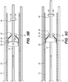
- Various embodiments of the floating element 50/50'/50" are depicted in FIGS. 6-8 .
- a floating element 50a comprises a funnel-like configuration, where the engaging portion 52 includes a bent section 55 disposed between two straight sections 54 and 56.
- the bent section 55 is configured to be elastically compressible, for instance, by heat-setting a stainless steel or shape memory alloy (e.g., nitinol).
- the engaging portion 52 extends from the annular portion 51 of the floating element 50a, and is formed of suitable filaments or ribbons woven, braided or formed into a mesh. It should be appreciated that the engaging portion 52 of the floating element 50a may be formed of a solid material, such as a liner, cover, or the like. Alternatively, the liner or cover may be permeable, porous, or includes apertures or perforations (not shown).
- a floating element 50b comprises a flower-like configuration, where the engaging portion 52 includes a plurality of petal-like elements 52a-g extending from the annular portion 51.
- the petal-like elements 52a-g may be formed by looped filaments 57 coupled to the annular portion 51, where each of the looped filament 57 may have a respective braided cover 59 disposed therein.
- the petal-like elements 52a-g of the engaging portion 52 of the floating element 50b may be formed by the looped filaments 57 without any braided cover disposed therein, or the petal-like elements 52a-g may be formed of a solid material, such as a liner, cover, or the like. Alternatively, the liner or cover may be permeable, porous, or includes apertures or perforations (not shown).
- the petal-like elements 52a-g may overlap with respective adjacently disposed petal-like elements, as shown in FIG. 7 .
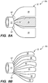
- the engaging portion 52 of a floating element 50c comprises a plurality of flaps 60 having respective ends 60' coupled to or extending from the annular portion 51. It should be appreciated that the plurality of flaps 160 of the engaging portion 52 of the floating element 50c may be permeable, porous, or includes apertures or perforations (not shown).
- the implant delivery system 10 is introduced into the vasculature of a patient in a conventional manner, such that the distal portion 16 of the elongate member 12 is adjacent a target site within the vasculature of the patient (step 102).
- the delivery wire 31 is axially translated in the distal direction relative to the elongated member 12, while limiting linear translation of the first (in this case the distal) floating element 50' between the first (in this case, the distal) engaging bumper 42' and the first (in this case, the distal) stopper bumper 44' (step 104).
- the distal engaging bumper 42' is engaged with the engaging portion 52' of the distal floating element 50', such that the distal floating element 50' radially expands outward to frictionally engage the implant 20 (step 106).
- the delivery wire 31 is further axially translated relative to the elongate member 12 in the distal direction, thereby advancing the implant 20 within the lumen 17 of the elongate member 12 (step 108).
- the delivery wire 31 is axially translated relative to the elongate member 12 until the implant 20 at least partially deploys out of the lumen 17 of the elongate member 12 (step 110).
- the implant 20 may be resheathed back into the elongate member 20 if it is decided that the deployment site of the implant 20 is not inaccurate.
- the delivery wire 31 is axially translated relative to the elongate member 12 in the proximal direction, while limiting linear translation of the second (in this case the proximal) floating element 50" between the second (in this case, the proximal) engaging bumper 42" and the second (in this case, the proximal) stopper bumper 44" (step 112).
- the distal engaging bumper 42' is disengaged from the engaging portion 52' of the distal floating element 50', such that the distal floating element 50' radially contracts inwards to release the implant 20 (step 114).
- the proximal engaging bumper 42" is engaged with the engaging portion 52 of the proximal floating element 50", such that the proximal floating element 50" radially expands outward to frictionally engage the implant 20 (step 116).
- the delivery wire 31 is further axially translated relative to the elongate member 12 in the proximal direction, thereby resheathing the implant 20 within the lumen 17 of the elongate member 12 (step 118).
- the distal portion 16 of the elongate member 12 can be repositioned (step 120), and steps 102-110, and if necessary steps 112-118, can be repeated.
Description
- The present disclosure relates generally to medical devices and, more particularly, to devices for delivering an implant to a target site in a blood or other body vessel.
- The use of intravascular medical devices has become an effective method for treating many types of vascular disease. In general, a suitable intravascular device is inserted into the vascular system of the patient and navigated through the vasculature to a desired target site. Using this method, virtually any target site in the patient's vascular system may be accessed, including the coronary, cerebral, and peripheral vasculature.
- Medical implants, such as stents, stent grafts, flow-diverters, and vena cava filters, are often utilized in combination with a delivery device for placement at a desired location within the body. A medical implant, such as a stent, may be loaded into a stent delivery device and then introduced into the lumen of a body vessel in a configuration having a reduced diameter. Once delivered to a target location within the body, the stent may then be expanded to an enlarged configuration within the vessel to support and reinforce the vessel wall while maintaining the vessel in an open, unobstructed condition. The stent may be configured to be self-expanding, expanded by a stored potential radial force such as a balloon, or a combination of self-expanding and balloon expanded.
- U.S. Patent Application published
US 2014/0200648 A1 discloses an implant delivery system according to the preamble of claim 1. - There is an ongoing need to provide alternative stent delivery devices that delivery medical implants into the vasculature of a patient.
- In accordance with the invention, an implant delivery system comprises an elongate tubular member having a lumen, a tubular implant coaxially disposed within the lumen of the elongate tubular member, and a delivery assembly having a distal portion coaxially disposed within tubular implant, the delivery assembly comprises a delivery wire, an engaging bumper fixedly coupled to the delivery wire, a stopper bumper fixedly coupled to the delivery wire, and a floating element slidably coupled around the delivery wire and disposed between the bumpers, the floating element has an engaging portion configured to engage the engaging bumper when the delivery wire is axially translated relative to the elongate member in a first direction, wherein the floating element is configured to radially expand (e.g., by flaring outward) to frictionally engage the implant when the engaging portion of the floating element engages the engaging bumper.
- Further developments of the invention are according to dependent claims 2-11.
- In one embodiment, the floating element comprises an annular portion slidably disposed around the delivery wire. The annular portion is configured to contact the stopper bumper when the delivery wire is axially translated relative to the elongate member in a second direction opposite to the first direction. The floating element is configured to maintain a radially unexpanded configuration in which the floating element does not frictionally engage the implant when the annular portion of the floating element contacts the stopper bumper. In various embodiments, the engaging portion of the floating element has an inner surface, and the engaging bumper has an outer surface that engages the inner surface of the floating element when the delivery wire is axially translated relative to the elongate member in the first direction. For example, the outer surface of the engaging bumper may taper inwards towards the engaging portion of the floating element.
- In one embodiment, the annular portion of the floating element has an abutting surface and the stopper bumper has a corresponding abutting surface that abuts the abutting surface of the floating element when the delivery wire is axially translated relative to the elongate member in the second direction. In this case, the abutting surface of the stopper bumper may be substantially perpendicular to the second direction.
- The engaging portion of the floating element may have one of a funnel-like, flower-like, and skirt-like configuration. For example, the engaging portion of the floating element may have a funnel-like configuration including an elastically compressible bent section disposed between two straight sections. The engaging portion of the floating element may have a flower-like configuration including a plurality of petal-like elements. The engaging portion of the floating element may have a flower-like configuration including a plurality of flaps.
- Other and further aspects and features of embodiments of the disclosed inventions will become apparent from the ensuing detailed description in view of the accompanying figures.
- The drawings illustrate the design and utility of preferred embodiments of the disclosed inventions, in which similar elements are referred to by common reference numerals. It should be noted that the figures are not drawn to scale and that elements of similar structures or functions are represented by like reference numerals throughout the figures. It should also be noted that the figures are only intended to facilitate the description of the embodiments, without intention to be an exhaustive description or as a limitation on the scope of the disclosed inventions, which is defined only by the appended claims. In addition, the illustrated embodiments need not have all the aspects or advantages shown, and an aspect or an advantage described in conjunction with a particular embodiment is not necessarily limited to that embodiment and can be practiced in other embodiments, even if not so illustrated. In order to better appreciate how the above-recited and other advantages and objects are obtained, a more particular description of the disclosed inventions briefly described above will be rendered by reference to specific embodiments thereof, which are illustrated in the accompanying drawings, in which:
-
FIG. 1 is a side view of an implant delivery system constructed according to one embodiment of the disclosed inventions, with a distal region of the system shown in an inset; -
FIG. 2 is a cross-sectional view of the distal portion of the implant delivery system constructed according to one embodiment of the disclosed inventions; -
FIG. 3 is a cross-sectional view of the implant delivery system ofFIG. 2 , showing advancement of the delivery assembly and engaging the implant for delivery; -
FIG. 4 is a cross-sectional view of the implant delivery system ofFIG. 2 , showing withdrawal of the delivery assembly and engaging the implant for re-sheathing; -
FIGS. 5A-5D are cross-sectional views an alternative embodiment of the implant delivery system ofFIG. 2 , particularly showing the process of engaging the implant; -
FIG. 6 is a perspective view of one embodiment of a floating element that can be used in the implant delivery system ofFIG. 1 orFIG. 5 ; -
FIG. 7 is a perspective view of another embodiment of a floating element that can be used in the implant delivery system ofFIG. 1 orFIG. 5 ; -
FIGS. 8A-8B are perspective views of embodiments of a floating element that can be used in the implant delivery system ofFIG. 1 orFIG. 5 ; and -
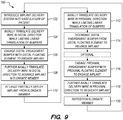
FIG. 9 is a flow diagram illustrating one method of operating the implant delivery system ofFIG. 2 . - Referring first to
FIG. 1 , one embodiment of animplant delivery system 10 constructed in accordance with one embodiment of the disclosed inventions will be described. Theimplant delivery system 10 generally comprises an elongatetubular member 12, a tubular implant 20 (not shown inFIG. 1 ), and adelivery assembly 30. - The
elongate member 12 has a tubular configuration, and can, e.g., take the form of a sheath, catheter, micro-catheter or the like. Theelongate member 12 has aproximal portion 13, adistal portion 16, and alumen 17 extending through theelongate member 12 between theproximal portion 13 and thedistal portion 16. Theproximal section 13 of theelongate member 12 remains outside of the patient and accessible to the operator when theimplant delivery system 10 is in use, while thedistal portion 16 of theelongate member 12 is sized and dimensioned to reach remote locations of a vasculature and is configured to deliver theimplant 20 to a target location in a patient's body, such as an occlusion in a blood vessel, in a blood vessel adjacent to an aneurysm neck, a bifurcated blood vessel, or the like. Theimplant delivery system 10 has at least onefluid port 15 in fluid communication with theelongate member 12, which is used to introduce fluids into theelongate member 12. Theimplant 20 anddelivery assembly 30 are disposed in thelumen 17 of theelongate member 12 of theimplant delivery system 10, as better appreciated inFIG. 2 . - The
implant 20, such a stent or a flow diverter, includes a tubular resilient member having aproximal portion 22, adistal portion 24, and defining an inner lumen 26 extending therebetween (FIG. 2 ). Theimplant 20 has a delivery configuration when disposed within thelumen 17 of theelongate member 12 and/or is radially constrained by theelongate member 12. Theimplant 20 is biased to expand radially outwards into a deployed configuration in which theimplant 20 is expanded when deployed out of theelongate member 12. Theimplant 20 may be constructed from a variety of materials such as stainless steel, elgiloy, nickel, titanium, nitinol, shape memory polymers, or combinations thereof. Theimplant 20 may also be formed in a variety of manners as well. For example, theimplant 20 may be formed by etching or cutting a pattern from a tube or sheet of stent material; a sheet of stent material may be cut or etched according to a desired stent pattern whereupon the sheet may be rolled or otherwise formed into the desired substantially tubular, bifurcated or other shape. For theimplant 20, one or more wires or ribbons of stent material may be woven, braided or otherwise formed into a desired shape and pattern. Theimplant 20 may include further components that are welded, bonded or otherwise engaged to one another. Theimplant 20 may include a non-porous, non-permeable biocompatible material, cover or the like, when theimplant 20 is used as a blood flow diverter. - The
implant delivery system 10 may be used in an "over-the-wire" configuration, wherein theelongate member 12 is introduced into the patient over a guidewire which has been previously introduced, and theelongate member 12 extends over the entire length of the guidewire (not shown). Alternatively, theimplant delivery system 10 may be used in a "rapid-exchange" configuration, where a guidewire extends through only a distal portion of theimplant delivery system 10 from a guidewire port (not shown). In other alternative embodiments, theimplant delivery system 10 may be introduced into the patient after a guidewire had been withdrawn leaving a sheath or access catheter distal portion at the target site for theassembly 10 to navigate through the vasculature of the patient within the sheath or access catheter. - The
implant delivery system 10 may include one or more, or a plurality of regions along its length having different configurations and/or characteristics. For example, thedistal portion 16 of theelongate member 12 may have an outer diameter less than the outer diameter of theproximal portion 13 to reduce the profile of thedistal portion 16 and facilitate navigation in tortuous vasculature (FIG. 1 ). Furthermore, thedistal portion 16 may be more flexible than theproximal portion 13. Generally, theproximal portion 13 may be formed from material that is stiffer than thedistal portion 16 of theelongate member 12, so that theproximal portion 13 has sufficient pushability to advance through the patient's vascular system, while thedistal portion 16 may be formed of a more flexible material so that thedistal portion 16 may remain flexible and track more easily over a guidewire to access remote locations in tortuous regions of the vasculature. Theelongate member 12 may be composed of suitable polymeric materials, metals and/or alloys, such as polyethylene, stainless steel or other suitable biocompatible materials or combinations thereof. In some instances, theproximal portion 13 may include a reinforcement layer, such a braided layer or coiled layer to enhance the pushability of theelongate member 12. Theelongate member 12 may include a transition region between theproximal portion 13 and thedistal portion 16. - Referring further to
FIG. 2 , theimplant 20 is coaxially disposed within thedistal portion 16 ofelongate member 12, and thedelivery assembly 30 is coaxially disposed and axially movable relative to theelongate member 12 and theimplant 20. Thedelivery assembly 30 is configured to engage theimplant 20 when thesystem 30 is axially translated relative to theelongate member 12 for delivery of theimplant 20 into a target site of a patient. The interface between thedelivery assembly 30 and theimplant 20 will be described in further detail below. - The
delivery assembly 30 comprises adelivery wire 31 having aproximal region 32 and a distal region 33 (FIG. 1 ). Thedelivery wire 31 may be made of a conventional guidewire, torqueable cable tube, a hypotube or the like. In either case, there are numerous materials that can be used for thedelivery wire 31 to achieve the desired properties that are commonly associated with medical devices. Some examples can include metals, metal alloys, polymers, metal-polymer composites, and the like, or any other suitable material. For example, thedelivery wire 31 may include nickel-titanium alloy, stainless steel, a composite of nickel-titanium alloy and stainless steel. In some cases, thedelivery wire 31 can be made of the same material along its length, or in some embodiments, can include portions or sections made of different materials. In some embodiments, the material used to construct thedelivery wire 31 is chosen to impart varying flexibility and stiffness characteristics to different portions of thedelivery wire 31. For example, the proximal region and thedistal region 33 of thedelivery wire 31 may be formed of different materials, such as materials having different moduli of elasticity, resulting in a difference in flexibility. For example, theproximal region 32 can be formed of stainless steel, and thedistal region 33 can be formed of a nickel-titanium alloy. However, any suitable material or combination of material may be used for thedelivery wire 31, as desired. - The
delivery wire 31 may further include a distal shapeable or pre-shaped atraumatic end 34 (FIG. 2 ), which may aid the advancement of thedelivery wire 31. In some embodiments, thedistal end 34 may include a coil placed over a portion of a distal end of the delivery wire 31 (not shown) or, alternatively, may include a material melted down and placed over a portion of thedistal end 34 of thedelivery wire 31. In some embodiments, thedistal end 34 may include a radiopaque material to aid in visualization. Additionally, thedistal end 34 of thedelivery wire 31 may be floppy and steerable using pull wires (not shown) to facilitate tracking of thedelivery assembly 30 through a vessel to reach a target site. Although not illustrated, it is contemplated that thedistal end 34 of thedelivery wire 31 may include one or more tapered sections, as desired. - The
delivery wire 31 may optionally include one or more bands (not shown) in thedistal region 33 of thedelivery wire 31. The bands may be formed integrally into thedelivery wire 31, or they may be separately formed from thedelivery wire 31 and attached thereto. In some embodiments, the bands may be disposed on thedelivery wire 31. The bands may have a diameter greater than the diameter of the surrounding thedelivery wire 31. Bands may be formed of any suitable material, such as metals, metal alloys, polymers, metal-polymer composites, and the like, or any other suitable material, as well as any radiopaque material, as desired. Alternatively, it is contemplated that thedelivery wire 31 may include one or more recesses instead of providing bands, if desired. - Significantly, the
delivery assembly 30 comprises at least one set ofbumpers 40 fixedly coupled to thedelivery wire 31, and a floatingelement 50 slidably coupled to thedelivery wire 31. In the embodiment ofFIG. 2 , two sets of bumpers 40 (a first set of distal bumpers 40' and a second set ofproximal bumpers 40") are disposed at thedistal portion 32 of thedelivery wire 31, with each set having a respective floatingelement 50'/50" therebetween. In particular, the distal bumpers 40' include a distal engagingbumper 42' and a distal stopper bumper 44', with a distal floatingelement 50' therebetween, and theproximal bumpers 40" include a proximal engagingbumper 42" and aproximal stopper bumper 44", with a proximal floatingelement 50" therebetween. The engagingbumpers 42/42'/42" and thestopper bumpers 44/44'/44" are configured to limit translation of the respective floatingelements 50/50'/50" therebetween. Additionally, the engagingbumpers 42/42'/42" are configured to interface with the respective floatingelements 50/50'/50" to engage (i.e., frictionally engage) theimplant 20 for delivery to a target site (FIGS. 3 ,5A-D ) and/or re-sheathing theimplant 20 into the elongate member 12 (FIG. 4 ). - Each floating
element 50/50'/50" has anannular portion 51/51'/51", such as a collar, ring or the like, and engagingportion 52/52'/52" having aninner surface 53/53'/53" configured to interface with anouter surface 43/43'/43" of the engagingbumper 42/42'/42" when thedelivery assembly 30 is actuated, which is described in further detail below. - Between the distal set of bumpers 40', the engaging portion 52' of the distal floating
element 50' is proximately disposed to the annular portion 51' of the distal floatingelement 50', such that the interface between the distal engagingbumper 42' and engaging portion 52' of the distal floatingelement 50' is configured to engage theimplant 20 when thedelivery wire 31 is advanced or translated in the distal direction for delivery of theimplant 20 into the target site of the patient (FIG. 3 ). - In contrast, between the proximal set of
bumpers 40", the engagingportion 52" of the proximal floatingelement 50" is distally disposed to theannular portion 51 of the proximal floatingelement 50", such that the interface between the proximal engagingbumper 42" and engagingportion 52" of the proximal floatingelement 50" is configured to engage theimplant 20 when thedelivery wire 31 is withdrawn or translated in the proximal direction for re-sheathing of theimplant 20 into the elongate member 12 (FIG. 4 ). - As shown in
FIG. 3 , thedelivery assembly 30 is actuated by advancing (i.e., distally translating, axially moving) thedelivery wire 31 relative to theelongate member 12. When thedelivery wire 31 is advanced relative to theelongate member 12, the distal engagingbumper 42' interfaces with the engaging portion 52' of the distal floatingelement 50', wherein the outer surface 43' of the engagingbumper 42' contacts the inner surface 53' of the engaging portion 52', so that the engaging portion 52' of the distal floatingelement 50' is disposed between the distal engagingbumper 42' and theimplant 20. The interface between the distal engagingbumper 42' and the engaging portion 52' of the distal floatingelement 50' exerts a radially outward force on aninterior surface 25 of theimplant 20. This radially outward force is sufficient to contact and frictionally engage theimplant 20 so as to advance and deliver theimplant 20 to a target site when thedelivery wire 31 advances relative to theelongate member 12. Furthermore, when thedelivery wire 31 is advanced relative to theelongate member 12, theproximal stopper bumper 44" contacts theannular portion 51" of the proximal floatingelement 50", advancing and distally pushing the proximal floatingelement 50" along with the advancement of thedelivery wire 31. As shown inFIG. 3 , the proximal floatingelement 50" does not frictionally engage theimplant 20 during advancement of thedelivery wire 31. - As shown in
FIG. 4 , thedelivery assembly 30 is actuated by withdrawing (i.e., proximately translating, axially moving) thedelivery wire 31 relative to theelongate member 12. When thedelivery wire 31 is withdrawn relative to theelongate member 12, the proximal engagingbumper 42" interfaces with the engagingportion 52" of the proximal floatingelement 50", wherein theouter surface 43 of the engagingbumper 42" contacts theinner surface 53" of the engagingportion 52", so that the engagingportion 52" of the proximal floatingelement 50" is disposed between the proximal engagingbumper 42" and theimplant 20. The interface between the proximal engagingbumper 42" and the engagingportion 52 of the proximal floatingelement 50" exerts a radially outward force on theinterior surface 25 of theimplant 20. This radially outward force is sufficient to frictionally engage theimplant 20 so as to withdraw and re-sheath theimplant 20 when thedelivery wire 31 is withdrawn relative to theelongate member 12. Furthermore, when thedelivery wire 31 is withdrawn relative to theelongate member 12, the distal stopper bumper 44' contacts the annular portion 51' of the distal floatingelement 50', withdrawing and proximally pushing the distal floatingelement 50' along with the withdrawal of thedelivery wire 31. As shown inFIG. 4 , the distal floatingelement 50' does not frictionally engage theimplant 20 during withdrawal of thedelivery wire 31. - Thus, as can be appreciated, the
delivery assembly 30 of theimplant delivery system 10 comprises a bi-directional actuation. Particularly, as shown inFIG. 3 , when thedelivery wire 31 is axially translated relative to theelongate member 12 in a first direction (i.e., advanced in a distal direction), theimplant 20 is engaged by the interface between the distal engagingbumper 42' and the engaging portion 52' of the distal floatingelement 50', while the proximal floatingelement 50" does not engage theimplant 20. Conversely, as shown inFIG. 4 , when thedelivery wire 31 is axially translated relative to theelongate member 12 in a second direction, opposite to the first direction (i.e., withdrawn in a proximal direction), theimplant 20 is engaged by the interface between the proximal engagingbumper 42" and the engagingportion 52" of the proximal floatingelement 50", while the distal floatingelement 50' does not engage theimplant 20. Thebi-directional delivery assembly 30 provides the operator of theimplant delivery system 10 with the advantage of being able to both deliver or re-sheath theimplant 20 by either advancing or withdrawing thedelivery wire 31 relative to theelongate member 12. - While the embodiment depicted in
FIGS. 2-4 comprises adelivery assembly 30 having two sets ofbumpers 40' and 40", each having a respective floatingmember 50'/50", an alternative embodiment of thedelivery assembly 30 may have more than two sets ofbumpers 40 and floatingmembers 50. Still another embodiment of thedelivery assembly 30 may comprise only one set ofbumpers 40 with only one floatingmember 50. - For example, as shown in
FIGS. 5A-D , thedelivery assembly 30 comprises one set ofbumpers 40 and one floatingelement 50 for delivery of theimplant 20 into the target site. Thedelivery assembly 30 is actuated by advancing (i.e., distally translating, axially moving) thedelivery wire 31 relative to theelongate member 12. When thedelivery wire 31 is advanced relative to theelongate member 12, the engagingbumper 42 approaches the floating element 50 (FIGS. 5A-B ), and as thedelivery wire 31 further advances, theouter surface 43 of the engagingbumper 42 interfaces with (i.e., contacts) theinner surface 53 the engagingportion 52 of the floating element 50 (FIG. 5C ), so that the engagingportion 52 of the floatingelement 50 is disposed between the engagingbumper 42 and theimplant 20, frictionally engaging the implant 20 (FIG. 5D ). As best seen inFIG. 5D , the interface between the engagingbumper 42 and the engagingportion 52 of the floatingelement 50 exerts a radially outward force (shown by arrows inFIG. 5D ) on aninterior surface 25 of theimplant 20. This radially outward force is sufficient to frictionally engageimplant 20 so as to advance the implant within theelongate member 12, and deliver theimplant 20 to a target site when thedelivery wire 31 advances relative to theelongate member 12. - In the embodiments of
FIGS. 2-5D , each floatingelement 50/50'/50" is configured to radially expand outward (e.g., by flaring outward) to frictionally engage theimplant 20 when the engagingportion 52/52'/52" of the floatingelement 50/50'/50" engages the respective engagingbumper 42/42'/42". In some embodiments, the engagingportion 52/52'/52" of the floating elements 5050'/50" is dimensioned and sized to partially enter or occupy openings/cells in the implant 20 (FIG. 5D ), thereby allowing further engagement and/or frictional forces between thedelivery assembly 30 and theimplant 20. This design assists the axial displacement of theimplant 20 relative to theelongate element 12, further facilitating delivery or re-sheathing of theimplant 20. - In these embodiments and as best seen in
FIG. 5C , theouter surface 43 of the engagingbumper 42 engages theinner surface 53 of the floatingelement 50 to radially expand the floatingelement 50 outwardly and frictionally contact and/or engage theimplant 20 for translation relative to theelongate element 12. To facilitate engagement between the engagingportion 52 of the floatingelement 50 and the respective engagingbumper 42, and the consequential outward radial expansion of the floatingelement 52, in the illustrated embodiments, theouter surface 43 of the engagingbumper 42 tapers inwards towards the engagingportion 52 of the respective floatingelement 52. While the engagingbumpers 42/42'/42" depicted inFIGS. 2-5D comprise a disk-shape having a tapered annular portion, the engagingbumpers 42/42'/42" may include a variety of configurations having any cross-section, such as irregular shapes, as long as at least one cross-sectional dimension is suitable to interface with theinner surface 53/53'/53" of the engagingportion 52/52'/52" of the floatingelement 50/50'/50" and frictionally engage theimplant 20, as previously described. - In the embodiments of
FIGS. 2-5D , each floatingelement 50/50'/50" is configured to not radially expand outwardly (e.g., by not flaring outwardly), such that there is no frictional engagement with theimplant 20 when the floatingelement 50/50'/50" engages therespective stopper bumper 44/44'/44". In these embodiments, theannular portion 51/51'/51" of each floatingelement 50/50'/50" has an abuttingsurface 58/58'/58", and therespective stopper bumper 44/44'/44" has an abuttingsurface 48/48'/48" that abuts the abuttingsurface 58/58'/58" of the floatingelement 50/50'/50" to axially displace the floatingelement 50/50'/50" relative to theimplant 20. To facilitate engagement between the floatingelement 50/50'/50" and therespective stopper bumper 44/44'/44", and the consequential axial displacement of the floatingelement 50/50'/50" relative to theimplant 20, the abuttingsurface 58/58'/58" of theannular portion 51/51'/51" of each floatingelement 50/50'/50" and the abuttingsurface 48/48'/48" of thestopper bumper 44/44'/44" are both perpendicular to the axial movement of the floatingelement 50/50'/50". While thestopper bumpers 44/44'/44" depicted inFIGS. 2-5D comprise a disk-shape configuration, and thestopper bumpers 44/44'/44" may comprise a variety of configuration, including irregular shapes, as long as at thestopper bumpers 44/44'/44" axially translates the floatingelement 50/50'/50" over thedelivery wire 31 relative to theimplant 20, as previously described. - As depicted in
FIGS. 2-5D , the engagingbumpers 42/42'/42" and thestopper bumpers 44/44'/44" have respective cross-sectional dimensions that are smaller than the inner diameter of theimplant 20 in the delivery configuration, when theimplant 20 is disposed within thelumen 17 of theelongate member 12. In the embodiments ofFIGS. 2-4 , the engagingbumpers 42/42'/42" have a cross-sectional dimension larger than thestopper bumpers 44/44'/44". In the embodiments ofFIGS. 5A-D , the engagingbumper 42/42'/42" has a cross-sectional dimension substantially similar to thestopper bumper 44/44'/44". It should be appreciated that variations of the relative dimensions of the engagingbumpers 42/42'/42" and thestopper bumpers 44/44'/44" may be suitable in some embodiments. - In the embodiments depicted in
FIGS. 2-8B , the engagingportion 52/52'/52" extending from theannular portion 51/51'/51" of the floatingelement 50/50'/50" is composed of suitable biocompatible material configured to be elastically compressible, for instance, stainless steel, elgiloy, nickel, titanium, nitinol, shape memory polymers, or combinations thereof. There are numerous materials that can be used for floatingelement 50/50'/50" to achieve the desired properties for the interface of the engagingportion 52/52'/52" with the engagingbumper 42/42'/42" of thedelivery assembly 30. Some examples can include metals, metal alloys, polymers, metal-polymer composites, and the like, or any other suitable material. Examples of suitable metals and metal alloys can include stainless steel, nickel-titanium alloy such as a superelastic (i.e., pseudoelastic) or linear elastic nitinol; nickel-chromium alloy; nickel-chromium-iron alloy; cobalt alloy; tungsten or tungsten alloys; tantalum or tantalum alloys, gold or gold alloys, or the like; or other suitable metals, or combinations or alloys thereof. Examples of some suitable polymers can include, but are not limited to, polyoxymethylene (POM), polybutylene terephthalate (PBT), polyether block ester, polyether block amide (PEBA), fluorinated ethylene propylene (FEP), polyethylene (PE), polypropylene (PP), polyvinylchloride (PVC), polyurethane, polytetrafluoroethylene (PTFE), polyether-ether ketone (PEEK), polyimide, polyamide, polyphenylene sulfide (PPS), polyphenylene oxide (PPO), polysufone, nylon, perfluoro(propyl vinyl ether) (PFA), polyether-ester, polymer/metal composites, or mixtures, blends or combinations thereof. Further, the engagingportion 52/52'/52" of the floatingdevice 50/50'/50" may be formed by etching or cutting a pattern from a tube or sheet, or may be formed by one or more wires or ribbons of suitable materials woven, braided or otherwise formed into a desired shape and pattern. Further, the engagingbumpers 42/42'/42" and/or thestopper bumpers 44/44'/44" may be radiopaque, in which case they function as markers to facilitate determination ofdelivery wire 31 position. - The engaging
portion 52/52'/52" of each floatingelement 50/50'/50" may have one of a funnel-like, flower-like, and skirt-like configuration. Various embodiments of the floatingelement 50/50'/50" are depicted inFIGS. 6-8 . For example, with reference toFIG. 6 , a floatingelement 50a comprises a funnel-like configuration, where the engagingportion 52 includes abent section 55 disposed between twostraight sections bent section 55 is configured to be elastically compressible, for instance, by heat-setting a stainless steel or shape memory alloy (e.g., nitinol). The engagingportion 52 extends from theannular portion 51 of the floatingelement 50a, and is formed of suitable filaments or ribbons woven, braided or formed into a mesh. It should be appreciated that the engagingportion 52 of the floatingelement 50a may be formed of a solid material, such as a liner, cover, or the like. Alternatively, the liner or cover may be permeable, porous, or includes apertures or perforations (not shown). - With reference to
FIG. 7 , a floatingelement 50b comprises a flower-like configuration, where the engagingportion 52 includes a plurality of petal-like elements 52a-g extending from theannular portion 51. The petal-like elements 52a-g may be formed by loopedfilaments 57 coupled to theannular portion 51, where each of the loopedfilament 57 may have a respective braided cover 59 disposed therein. It should be appreciated that the petal-like elements 52a-g of the engagingportion 52 of the floatingelement 50b may be formed by the loopedfilaments 57 without any braided cover disposed therein, or the petal-like elements 52a-g may be formed of a solid material, such as a liner, cover, or the like. Alternatively, the liner or cover may be permeable, porous, or includes apertures or perforations (not shown). The petal-like elements 52a-g may overlap with respective adjacently disposed petal-like elements, as shown inFIG. 7 . - With reference to
FIGS. 8A-8B , the engagingportion 52 of a floatingelement 50c comprises a plurality offlaps 60 having respective ends 60' coupled to or extending from theannular portion 51. It should be appreciated that the plurality of flaps 160 of the engagingportion 52 of the floatingelement 50c may be permeable, porous, or includes apertures or perforations (not shown). - Having described the function and structure of the
implant delivery system 10, onemethod 100 of using theimplant delivery system 10 illustrated inFIG. 2 will now be discussed inFIG. 9 . First, theimplant delivery system 10 is introduced into the vasculature of a patient in a conventional manner, such that thedistal portion 16 of theelongate member 12 is adjacent a target site within the vasculature of the patient (step 102). Next, thedelivery wire 31 is axially translated in the distal direction relative to theelongated member 12, while limiting linear translation of the first (in this case the distal) floatingelement 50' between the first (in this case, the distal) engagingbumper 42' and the first (in this case, the distal) stopper bumper 44' (step 104). Next, the distal engagingbumper 42' is engaged with the engaging portion 52' of the distal floatingelement 50', such that the distal floatingelement 50' radially expands outward to frictionally engage the implant 20 (step 106). Then, thedelivery wire 31 is further axially translated relative to theelongate member 12 in the distal direction, thereby advancing theimplant 20 within thelumen 17 of the elongate member 12 (step 108). Thedelivery wire 31 is axially translated relative to theelongate member 12 until theimplant 20 at least partially deploys out of thelumen 17 of the elongate member 12 (step 110). - If the
implant 20 is only partially deployed, theimplant 20 may be resheathed back into theelongate member 20 if it is decided that the deployment site of theimplant 20 is not inaccurate. In particular, thedelivery wire 31 is axially translated relative to theelongate member 12 in the proximal direction, while limiting linear translation of the second (in this case the proximal) floatingelement 50" between the second (in this case, the proximal) engagingbumper 42" and the second (in this case, the proximal)stopper bumper 44" (step 112). The distal engagingbumper 42' is disengaged from the engaging portion 52' of the distal floatingelement 50', such that the distal floatingelement 50' radially contracts inwards to release the implant 20 (step 114). Next, the proximal engagingbumper 42" is engaged with the engagingportion 52 of the proximal floatingelement 50", such that the proximal floatingelement 50" radially expands outward to frictionally engage the implant 20 (step 116). Optionally, thedelivery wire 31 is further axially translated relative to theelongate member 12 in the proximal direction, thereby resheathing theimplant 20 within thelumen 17 of the elongate member 12 (step 118). Thedistal portion 16 of theelongate member 12 can be repositioned (step 120), and steps 102-110, and if necessary steps 112-118, can be repeated. - Although particular embodiments of the disclosed inventions have been shown and described herein, it will be understood by those skilled in the art that they are not intended to limit the disclosed inventions, and it will be obvious to those skilled in the art that various changes and modifications may be made (e.g., the dimensions of various parts). The specification and drawings are, accordingly, to be regarded in an illustrative rather than restrictive sense.
Claims (11)
- An implant delivery system (10), comprising:an elongate tubular member (12) having a lumen (17);a tubular implant (20) coaxially disposed within the lumen (17) of the elongate tubular member (12); anda delivery assembly (30) having a distal portion coaxially disposed within tubular implant (20), the delivery assembly (30) comprising:a delivery wire (31);an engaging bumper (42; 42'; 42") fixedly coupled to the delivery wire (31); anda stopper bumper (44; 44'; 44") fixedly coupled to the delivery wire (31);characterized in that the implant delivery system further comprises:
a floating element (50; 50'; 50") slidably coupled around the delivery wire (31) and disposed between the bumpers (42, 44; 42', 44'; 42", 44"), the floating element (50; 50'; 50") comprising an engaging portion (52; 52'; 52") configured to engage the engaging bumper (42; 42'; 42") when the delivery wire (31) is axially translated relative to the elongate tubular member (12) in a first direction, wherein the floating element (50; 50'; 50") is configured to radially expand and frictionally engage the implant (20) when the engaging portion (52; 52'; 52") of the floating element (50; 50'; 50") engages the engaging bumper (42; 42'; 42"). - The implant delivery system (10) of claim 1, the floating element (50; 50'; 50") further comprising an annular portion (51; 51'; 51") slidably disposed around the delivery wire (31), the annular portion (51; 51'; 51") configured to contact the stopper bumper (44; 44'; 44") when the delivery wire (31) is axially translated relative to the elongate tubular member (12) in a second direction opposite to the first direction, and wherein the floating element (50; 50', 50") is configured to maintain a non-radially expanded configuration in which the floating element (50; 50'; 50") does not frictionally engage the implant (20) when the annular portion (51; 51'; 51") of the floating element (50; 50'; 50") contacts the stopper bumper (44; 44'; 44").
- The implant delivery system (10) of claim 2, wherein the annular portion (51; 51'; 51") of the floating element (50; 50'; 50") has an abutting surface (58; 58'; 58"), and the stopper bumper (44; 44'; 44") has an abutting surface (48; 48'; 48") that abuts the abutting surface (58; 58'; 58") of the floating element (50; 50'; 50") when the delivery wire (31) is axially translated relative to the elongate member (12) in the second direction.
- The implant delivery system (10) of claim 3, wherein the abutting surface (48; 48'; 48") of the stopper bumper (44; 44'; 44") is perpendicular to the second direction.
- The implant delivery system (10) of any of claims 1-4, wherein the floating element (50; 50'; 50") radially expands by flaring outward when the engaging portion (52; 52'; 52") of the floating element (50; 50'; 50") engages the engaging bumper (42; 42'; 42").
- The implant delivery system (10) of any of claims 1-5, wherein the engaging portion (52; 52'; 52") of the floating element (50; 50'; 50") has an inner surface (53; 53'; 53"), and the engaging bumper (42; 42'; 42") has an outer surface (43; 43'; 43") that contacts the inner surface (53; 53'; 53") of the floating element (50; 50'; 50") when the delivery wire (31) is axially translated relative to the elongate member (12) in the first direction.
- The implant delivery system (10) of claim 6, wherein the outer surface (43; 43'; 43") of the engaging bumper (42; 42'; 42") tapers inwards towards the engaging portion (52; 52'; 52") of the floating element (50; 50'; 50").
- The implant delivery system (10) of any of claims 1-7, wherein the engaging portion (52; 52'; 52") of the floating element (50; 50'; 50") has one of a funnel-like, flower-like, and skirt-like configuration.
- The implant delivery system (10) of claim 8, wherein the engaging portion (52) of the floating element (50) has a funnel-like configuration including an elastically compressible bent section (55) disposed between two straight sections (54, 56).
- The implant delivery system (10) of claim 8, wherein the engaging portion (52) of the floating element (50) has a flower-like configuration including a plurality of petal-like elements (52a-g).
- The implant delivery system (10) of claim 8, wherein the engaging portion (52) of the floating element (50) has a flower-like configuration including a plurality of flaps (60).
Applications Claiming Priority (2)
| Application Number | Priority Date | Filing Date | Title |
|---|---|---|---|
| US201762549233P | 2017-08-23 | 2017-08-23 | |
| PCT/US2018/047582 WO2019040652A1 (en) | 2017-08-23 | 2018-08-22 | Implant delivery system |
Publications (2)
| Publication Number | Publication Date |
|---|---|
| EP3672538A1 EP3672538A1 (en) | 2020-07-01 |
| EP3672538B1 true EP3672538B1 (en) | 2021-01-13 |
Family
ID=63452754
Family Applications (1)
| Application Number | Title | Priority Date | Filing Date |
|---|---|---|---|
| EP18762997.7A Active EP3672538B1 (en) | 2017-08-23 | 2018-08-22 | Implant delivery system |
Country Status (6)
| Country | Link |
|---|---|
| US (3) | US11083611B2 (en) |
| EP (1) | EP3672538B1 (en) |
| JP (1) | JP7198272B2 (en) |
| CN (2) | CN111031971B (en) |
| ES (1) | ES2864409T3 (en) |
| WO (1) | WO2019040652A1 (en) |
Citations (1)
| Publication number | Priority date | Publication date | Assignee | Title |
|---|---|---|---|---|
| EP2842525A1 (en) * | 2013-08-27 | 2015-03-04 | Covidien LP | Delivery of medical devices |
Family Cites Families (26)
| Publication number | Priority date | Publication date | Assignee | Title |
|---|---|---|---|---|
| US6761733B2 (en) * | 2001-04-11 | 2004-07-13 | Trivascular, Inc. | Delivery system and method for bifurcated endovascular graft |
| CN2572956Y (en) * | 2002-07-19 | 2003-09-17 | 黄秀虎 | Tight vest type massage device |
| JP4317475B2 (en) * | 2004-03-25 | 2009-08-19 | 株式会社パイオラックスメディカルデバイス | Tubular organ treatment device insertion device |
| WO2006127005A1 (en) * | 2005-05-25 | 2006-11-30 | Chestnut Medical Technologies, Inc. | System and method for delivering and deploying and occluding device within a vessel |
| US8092508B2 (en) * | 2006-03-30 | 2012-01-10 | Stryker Corporation | Implantable medical endoprosthesis delivery system |
| CA2934202A1 (en) * | 2006-10-22 | 2008-05-02 | Idev Technologies, Inc. | Methods for securing strand ends and the resulting devices |
| CN102006842A (en) * | 2008-03-27 | 2011-04-06 | 纽福克斯神经医疗公司 | Friction-release distal latch implant delivery system and components |
| MX338973B (en) * | 2011-01-14 | 2016-05-06 | Idev Technologies Inc | Stent delivery system with pusher assembly. |
| US8696731B2 (en) * | 2011-06-10 | 2014-04-15 | DePuy Synthes Products, LLC | Lock/floating marker band on pusher wire for self-expanding stents or medical devices |
| US9039752B2 (en) * | 2011-09-20 | 2015-05-26 | Aga Medical Corporation | Device and method for delivering a vascular device |
| US20130226278A1 (en) * | 2012-02-23 | 2013-08-29 | Tyco Healthcare Group Lp | Methods and apparatus for luminal stenting |
| DE102012104544A1 (en) * | 2012-05-25 | 2013-11-28 | Acandis Gmbh & Co. Kg | Delivery system for a medical functional element, set with such a delivery system and method for discharging a medical functional element from such a delivery system |
| JP5897408B2 (en) * | 2012-06-04 | 2016-03-30 | 株式会社カネカ | Stent delivery catheter |
| EP2676642A1 (en) * | 2012-06-18 | 2013-12-25 | Biotronik AG | Release device for releasing a medical implant from a catheter |
| US9155647B2 (en) * | 2012-07-18 | 2015-10-13 | Covidien Lp | Methods and apparatus for luminal stenting |
| CH707319A1 (en) * | 2012-12-11 | 2014-06-13 | Carag Ag | Stent applicator. |
| WO2014099626A1 (en) * | 2012-12-21 | 2014-06-26 | Stryker Corporation | Stent delivery system |
| US9295571B2 (en) | 2013-01-17 | 2016-03-29 | Covidien Lp | Methods and apparatus for luminal stenting |
| US20140277360A1 (en) * | 2013-03-13 | 2014-09-18 | DePuy Synthes Products, LLC | Delivery system for expandable stents |
| JP2014233592A (en) * | 2013-06-05 | 2014-12-15 | 朝日インテック株式会社 | Pusher guide wire |
| JP6154082B2 (en) * | 2014-04-08 | 2017-06-28 | ストライカー コーポレイションStryker Corporation | Implant delivery system |
| JP2016077765A (en) * | 2014-10-22 | 2016-05-16 | 朝日インテック株式会社 | Guide wire |
| CN205964238U (en) * | 2015-01-31 | 2017-02-22 | 灵活支架解决方案股份有限公司 | Install in canalis haemalis and can retrain stent delivery system again |
| JP6499497B2 (en) | 2015-04-15 | 2019-04-10 | 株式会社Pentas | Pusher guide wire |
| CN204909754U (en) * | 2015-07-14 | 2015-12-30 | 先健科技(深圳)有限公司 | Lumen support conveying system |
| CN207590810U (en) * | 2016-07-29 | 2018-07-10 | 上海沃比医疗科技有限公司 | Implantation material transport system |
-
2018
- 2018-08-22 CN CN201880054729.3A patent/CN111031971B/en active Active
- 2018-08-22 US US16/638,600 patent/US11083611B2/en active Active
- 2018-08-22 EP EP18762997.7A patent/EP3672538B1/en active Active
- 2018-08-22 ES ES18762997T patent/ES2864409T3/en active Active
- 2018-08-22 CN CN202111283275.7A patent/CN113827385A/en active Pending
- 2018-08-22 JP JP2020510539A patent/JP7198272B2/en active Active
- 2018-08-22 WO PCT/US2018/047582 patent/WO2019040652A1/en unknown
-
2021
- 2021-08-06 US US17/396,618 patent/US11730618B2/en active Active
-
2023
- 2023-06-30 US US18/346,133 patent/US20230346581A1/en active Pending
Patent Citations (1)
| Publication number | Priority date | Publication date | Assignee | Title |
|---|---|---|---|---|
| EP2842525A1 (en) * | 2013-08-27 | 2015-03-04 | Covidien LP | Delivery of medical devices |
Also Published As
| Publication number | Publication date |
|---|---|
| US11730618B2 (en) | 2023-08-22 |
| WO2019040652A1 (en) | 2019-02-28 |
| EP3672538A1 (en) | 2020-07-01 |
| US20200170817A1 (en) | 2020-06-04 |
| US20230346581A1 (en) | 2023-11-02 |
| CN111031971A (en) | 2020-04-17 |
| JP7198272B2 (en) | 2022-12-28 |
| CN113827385A (en) | 2021-12-24 |
| US20210361454A1 (en) | 2021-11-25 |
| JP2020531133A (en) | 2020-11-05 |
| ES2864409T3 (en) | 2021-10-13 |
| CN111031971B (en) | 2021-11-19 |
| US11083611B2 (en) | 2021-08-10 |
Similar Documents
| Publication | Publication Date | Title |
|---|---|---|
| EP3860530B1 (en) | Medical implant delivery system | |
| US20180008440A1 (en) | Implant delivery system and method of use | |
| US9254213B2 (en) | Stent delivery device | |
| US7955351B2 (en) | Rapid exchange catheters and embolic protection devices | |
| US20170049596A1 (en) | Implant delivery system and method of use | |
| EP2944292A1 (en) | Stent delivery device | |
| EP0864300A1 (en) | Delivery device for a medical device having a constricted region | |
| US20140180387A1 (en) | Stent delivery system | |
| EP2124814A2 (en) | Apparatus and methods for stent delivery with embolic protection | |
| CA2553979A1 (en) | Expandable intravascular retrieval device with dilator tip | |
| EP4096539A1 (en) | Apparatus and method for neurovascular endoluminal intervention | |
| EP1696824B1 (en) | Rapid exchange catheters with tandem lumens | |
| US20190223995A1 (en) | Device for delivery and retrieval of protection filters | |
| EP3672538B1 (en) | Implant delivery system | |
| EP3539515A1 (en) | Medical device delivery system including a support member | |
| US20230029736A1 (en) | Medical device delivery | |
| US10744017B2 (en) | Medical implant delivery system and method of use | |
| US10751208B2 (en) | Medical implant delivery system and method of use | |
| WO2024036004A1 (en) | Friction pad for deployment and resheathing of intravascular implant |
Legal Events
| Date | Code | Title | Description |
|---|---|---|---|
| STAA | Information on the status of an ep patent application or granted ep patent |
Free format text: STATUS: UNKNOWN |
|
| STAA | Information on the status of an ep patent application or granted ep patent |
Free format text: STATUS: THE INTERNATIONAL PUBLICATION HAS BEEN MADE |
|
| PUAI | Public reference made under article 153(3) epc to a published international application that has entered the european phase |
Free format text: ORIGINAL CODE: 0009012 |
|
| STAA | Information on the status of an ep patent application or granted ep patent |
Free format text: STATUS: REQUEST FOR EXAMINATION WAS MADE |
|
| 17P | Request for examination filed |
Effective date: 20200220 |
|
| AK | Designated contracting states |
Kind code of ref document: A1 Designated state(s): AL AT BE BG CH CY CZ DE DK EE ES FI FR GB GR HR HU IE IS IT LI LT LU LV MC MK MT NL NO PL PT RO RS SE SI SK SM TR |
|
| AX | Request for extension of the european patent |
Extension state: BA ME |
|
| GRAP | Despatch of communication of intention to grant a patent |
Free format text: ORIGINAL CODE: EPIDOSNIGR1 |
|
| STAA | Information on the status of an ep patent application or granted ep patent |
Free format text: STATUS: GRANT OF PATENT IS INTENDED |
|
| DAV | Request for validation of the european patent (deleted) | ||
| DAX | Request for extension of the european patent (deleted) | ||
| INTG | Intention to grant announced |
Effective date: 20200728 |
|
| GRAS | Grant fee paid |
Free format text: ORIGINAL CODE: EPIDOSNIGR3 |
|
| GRAA | (expected) grant |
Free format text: ORIGINAL CODE: 0009210 |
|
| STAA | Information on the status of an ep patent application or granted ep patent |
Free format text: STATUS: THE PATENT HAS BEEN GRANTED |
|
| AK | Designated contracting states |
Kind code of ref document: B1 Designated state(s): AL AT BE BG CH CY CZ DE DK EE ES FI FR GB GR HR HU IE IS IT LI LT LU LV MC MK MT NL NO PL PT RO RS SE SI SK SM TR |
|
| REG | Reference to a national code |
Ref country code: GB Ref legal event code: FG4D |
|
| REG | Reference to a national code |
Ref country code: CH Ref legal event code: EP |
|
| REG | Reference to a national code |
Ref country code: IE Ref legal event code: FG4D |
|
| REG | Reference to a national code |
Ref country code: DE Ref legal event code: R096 Ref document number: 602018011896 Country of ref document: DE |
|
| REG | Reference to a national code |
Ref country code: AT Ref legal event code: REF Ref document number: 1353995 Country of ref document: AT Kind code of ref document: T Effective date: 20210215 |
|
| REG | Reference to a national code |
Ref country code: NL Ref legal event code: FP |
|
| REG | Reference to a national code |
Ref country code: AT Ref legal event code: MK05 Ref document number: 1353995 Country of ref document: AT Kind code of ref document: T Effective date: 20210113 |
|
| REG | Reference to a national code |
Ref country code: LT Ref legal event code: MG9D |
|
| PG25 | Lapsed in a contracting state [announced via postgrant information from national office to epo] |
Ref country code: NO Free format text: LAPSE BECAUSE OF FAILURE TO SUBMIT A TRANSLATION OF THE DESCRIPTION OR TO PAY THE FEE WITHIN THE PRESCRIBED TIME-LIMIT Effective date: 20210413 Ref country code: PT Free format text: LAPSE BECAUSE OF FAILURE TO SUBMIT A TRANSLATION OF THE DESCRIPTION OR TO PAY THE FEE WITHIN THE PRESCRIBED TIME-LIMIT Effective date: 20210513 Ref country code: LT Free format text: LAPSE BECAUSE OF FAILURE TO SUBMIT A TRANSLATION OF THE DESCRIPTION OR TO PAY THE FEE WITHIN THE PRESCRIBED TIME-LIMIT Effective date: 20210113 Ref country code: FI Free format text: LAPSE BECAUSE OF FAILURE TO SUBMIT A TRANSLATION OF THE DESCRIPTION OR TO PAY THE FEE WITHIN THE PRESCRIBED TIME-LIMIT Effective date: 20210113 Ref country code: HR Free format text: LAPSE BECAUSE OF FAILURE TO SUBMIT A TRANSLATION OF THE DESCRIPTION OR TO PAY THE FEE WITHIN THE PRESCRIBED TIME-LIMIT Effective date: 20210113 Ref country code: GR Free format text: LAPSE BECAUSE OF FAILURE TO SUBMIT A TRANSLATION OF THE DESCRIPTION OR TO PAY THE FEE WITHIN THE PRESCRIBED TIME-LIMIT Effective date: 20210414 Ref country code: BG Free format text: LAPSE BECAUSE OF FAILURE TO SUBMIT A TRANSLATION OF THE DESCRIPTION OR TO PAY THE FEE WITHIN THE PRESCRIBED TIME-LIMIT Effective date: 20210413 |
|
| PG25 | Lapsed in a contracting state [announced via postgrant information from national office to epo] |
Ref country code: SE Free format text: LAPSE BECAUSE OF FAILURE TO SUBMIT A TRANSLATION OF THE DESCRIPTION OR TO PAY THE FEE WITHIN THE PRESCRIBED TIME-LIMIT Effective date: 20210113 Ref country code: AT Free format text: LAPSE BECAUSE OF FAILURE TO SUBMIT A TRANSLATION OF THE DESCRIPTION OR TO PAY THE FEE WITHIN THE PRESCRIBED TIME-LIMIT Effective date: 20210113 Ref country code: RS Free format text: LAPSE BECAUSE OF FAILURE TO SUBMIT A TRANSLATION OF THE DESCRIPTION OR TO PAY THE FEE WITHIN THE PRESCRIBED TIME-LIMIT Effective date: 20210113 Ref country code: LV Free format text: LAPSE BECAUSE OF FAILURE TO SUBMIT A TRANSLATION OF THE DESCRIPTION OR TO PAY THE FEE WITHIN THE PRESCRIBED TIME-LIMIT Effective date: 20210113 Ref country code: PL Free format text: LAPSE BECAUSE OF FAILURE TO SUBMIT A TRANSLATION OF THE DESCRIPTION OR TO PAY THE FEE WITHIN THE PRESCRIBED TIME-LIMIT Effective date: 20210113 |
|
| PG25 | Lapsed in a contracting state [announced via postgrant information from national office to epo] |
Ref country code: IS Free format text: LAPSE BECAUSE OF FAILURE TO SUBMIT A TRANSLATION OF THE DESCRIPTION OR TO PAY THE FEE WITHIN THE PRESCRIBED TIME-LIMIT Effective date: 20210513 |
|
| REG | Reference to a national code |
Ref country code: ES Ref legal event code: FG2A Ref document number: 2864409 Country of ref document: ES Kind code of ref document: T3 Effective date: 20211013 |
|
| REG | Reference to a national code |
Ref country code: DE Ref legal event code: R097 Ref document number: 602018011896 Country of ref document: DE |
|
| PG25 | Lapsed in a contracting state [announced via postgrant information from national office to epo] |
Ref country code: CZ Free format text: LAPSE BECAUSE OF FAILURE TO SUBMIT A TRANSLATION OF THE DESCRIPTION OR TO PAY THE FEE WITHIN THE PRESCRIBED TIME-LIMIT Effective date: 20210113 Ref country code: EE Free format text: LAPSE BECAUSE OF FAILURE TO SUBMIT A TRANSLATION OF THE DESCRIPTION OR TO PAY THE FEE WITHIN THE PRESCRIBED TIME-LIMIT Effective date: 20210113 Ref country code: SM Free format text: LAPSE BECAUSE OF FAILURE TO SUBMIT A TRANSLATION OF THE DESCRIPTION OR TO PAY THE FEE WITHIN THE PRESCRIBED TIME-LIMIT Effective date: 20210113 |
|
| PLBE | No opposition filed within time limit |
Free format text: ORIGINAL CODE: 0009261 |
|
| STAA | Information on the status of an ep patent application or granted ep patent |
Free format text: STATUS: NO OPPOSITION FILED WITHIN TIME LIMIT |
|
| PG25 | Lapsed in a contracting state [announced via postgrant information from national office to epo] |
Ref country code: DK Free format text: LAPSE BECAUSE OF FAILURE TO SUBMIT A TRANSLATION OF THE DESCRIPTION OR TO PAY THE FEE WITHIN THE PRESCRIBED TIME-LIMIT Effective date: 20210113 Ref country code: RO Free format text: LAPSE BECAUSE OF FAILURE TO SUBMIT A TRANSLATION OF THE DESCRIPTION OR TO PAY THE FEE WITHIN THE PRESCRIBED TIME-LIMIT Effective date: 20210113 Ref country code: SK Free format text: LAPSE BECAUSE OF FAILURE TO SUBMIT A TRANSLATION OF THE DESCRIPTION OR TO PAY THE FEE WITHIN THE PRESCRIBED TIME-LIMIT Effective date: 20210113 |
|
| REG | Reference to a national code |
Ref country code: GB Ref legal event code: 732E Free format text: REGISTERED BETWEEN 20211111 AND 20211117 |
|
| REG | Reference to a national code |
Ref country code: DE Ref legal event code: R081 Ref document number: 602018011896 Country of ref document: DE Owner name: STRYKER EUROPEAN OPERATIONS HOLDINGS LLC (N.D., US Free format text: FORMER OWNERS: STRYKER CORPORATION, KALAMAZOO, MICH., US; STRYKER EUROPEAN HOLDINGS I, LLC, KALAMAZOO, MICH., US Ref country code: DE Ref legal event code: R081 Ref document number: 602018011896 Country of ref document: DE Owner name: STRYKER CORPORATION, KALAMAZOO, US Free format text: FORMER OWNERS: STRYKER CORPORATION, KALAMAZOO, MICH., US; STRYKER EUROPEAN HOLDINGS I, LLC, KALAMAZOO, MICH., US Ref country code: DE Ref legal event code: R082 Ref document number: 602018011896 Country of ref document: DE Representative=s name: WUESTHOFF & WUESTHOFF, PATENTANWAELTE PARTG MB, DE Ref country code: DE Ref legal event code: R082 Ref document number: 602018011896 Country of ref document: DE Representative=s name: WUESTHOFF & WUESTHOFF PATENTANWAELTE UND RECHT, DE |
|
| 26N | No opposition filed |
Effective date: 20211014 |
|
| REG | Reference to a national code |
Ref country code: NL Ref legal event code: PD Owner name: STRYKER EUROPEAN HOLDINGS III, LLC; US Free format text: DETAILS ASSIGNMENT: CHANGE OF OWNER(S), ASSIGNMENT; FORMER OWNER NAME: STRYKER EUROPEAN HOLDINGS I, LLC Effective date: 20211203 Ref country code: NL Ref legal event code: HC Owner name: STRYKER EUROPEAN OPERATIONS HOLDINGS LLC; US Free format text: DETAILS ASSIGNMENT: CHANGE OF OWNER(S), CHANGE OF OWNER(S) NAME; FORMER OWNER NAME: STRYKER EUROPEAN HOLDINGS III, LLC Effective date: 20211203 |
|
| PG25 | Lapsed in a contracting state [announced via postgrant information from national office to epo] |
Ref country code: AL Free format text: LAPSE BECAUSE OF FAILURE TO SUBMIT A TRANSLATION OF THE DESCRIPTION OR TO PAY THE FEE WITHIN THE PRESCRIBED TIME-LIMIT Effective date: 20210113 |
|
| REG | Reference to a national code |
Ref country code: CH Ref legal event code: PL |
|
| PG25 | Lapsed in a contracting state [announced via postgrant information from national office to epo] |
Ref country code: MC Free format text: LAPSE BECAUSE OF FAILURE TO SUBMIT A TRANSLATION OF THE DESCRIPTION OR TO PAY THE FEE WITHIN THE PRESCRIBED TIME-LIMIT Effective date: 20210113 |
|
| REG | Reference to a national code |
Ref country code: BE Ref legal event code: MM Effective date: 20210831 |
|
| PG25 | Lapsed in a contracting state [announced via postgrant information from national office to epo] |
Ref country code: LI Free format text: LAPSE BECAUSE OF NON-PAYMENT OF DUE FEES Effective date: 20210831 Ref country code: CH Free format text: LAPSE BECAUSE OF NON-PAYMENT OF DUE FEES Effective date: 20210831 |
|
| REG | Reference to a national code |
Ref country code: ES Ref legal event code: PC2A Owner name: STRYKER EUROPEAN OPERATIONS HOLDINGS LLC Effective date: 20220427 |
|
| PG25 | Lapsed in a contracting state [announced via postgrant information from national office to epo] |
Ref country code: IS Free format text: LAPSE BECAUSE OF FAILURE TO SUBMIT A TRANSLATION OF THE DESCRIPTION OR TO PAY THE FEE WITHIN THE PRESCRIBED TIME-LIMIT Effective date: 20210513 Ref country code: LU Free format text: LAPSE BECAUSE OF NON-PAYMENT OF DUE FEES Effective date: 20210822 |
|
| PG25 | Lapsed in a contracting state [announced via postgrant information from national office to epo] |
Ref country code: BE Free format text: LAPSE BECAUSE OF NON-PAYMENT OF DUE FEES Effective date: 20210831 |
|
| P01 | Opt-out of the competence of the unified patent court (upc) registered |
Effective date: 20230523 |
|
| PG25 | Lapsed in a contracting state [announced via postgrant information from national office to epo] |
Ref country code: CY Free format text: LAPSE BECAUSE OF FAILURE TO SUBMIT A TRANSLATION OF THE DESCRIPTION OR TO PAY THE FEE WITHIN THE PRESCRIBED TIME-LIMIT Effective date: 20210113 |
|
| PG25 | Lapsed in a contracting state [announced via postgrant information from national office to epo] |
Ref country code: HU Free format text: LAPSE BECAUSE OF FAILURE TO SUBMIT A TRANSLATION OF THE DESCRIPTION OR TO PAY THE FEE WITHIN THE PRESCRIBED TIME-LIMIT; INVALID AB INITIO Effective date: 20180822 |
|
| PGFP | Annual fee paid to national office [announced via postgrant information from national office to epo] |
Ref country code: IE Payment date: 20230606 Year of fee payment: 6 |
|
| PGFP | Annual fee paid to national office [announced via postgrant information from national office to epo] |
Ref country code: NL Payment date: 20230719 Year of fee payment: 6 |
|
| PG25 | Lapsed in a contracting state [announced via postgrant information from national office to epo] |
Ref country code: SI Free format text: LAPSE BECAUSE OF FAILURE TO SUBMIT A TRANSLATION OF THE DESCRIPTION OR TO PAY THE FEE WITHIN THE PRESCRIBED TIME-LIMIT Effective date: 20210113 |
|
| PGFP | Annual fee paid to national office [announced via postgrant information from national office to epo] |
Ref country code: IT Payment date: 20230711 Year of fee payment: 6 Ref country code: GB Payment date: 20230629 Year of fee payment: 6 Ref country code: ES Payment date: 20230907 Year of fee payment: 6 |
|
| PGFP | Annual fee paid to national office [announced via postgrant information from national office to epo] |
Ref country code: FR Payment date: 20230703 Year of fee payment: 6 Ref country code: DE Payment date: 20230627 Year of fee payment: 6 |