EP3672284A2 - Otoplastic and use of an otoplastic - Google Patents
Otoplastic and use of an otoplastic Download PDFInfo
- Publication number
- EP3672284A2 EP3672284A2 EP19216558.7A EP19216558A EP3672284A2 EP 3672284 A2 EP3672284 A2 EP 3672284A2 EP 19216558 A EP19216558 A EP 19216558A EP 3672284 A2 EP3672284 A2 EP 3672284A2
- Authority
- EP
- European Patent Office
- Prior art keywords
- otoplastic
- section
- opening
- auditory canal
- base body
- Prior art date
- Legal status (The legal status is an assumption and is not a legal conclusion. Google has not performed a legal analysis and makes no representation as to the accuracy of the status listed.)
- Granted
Links
- 238000012360 testing method Methods 0.000 claims abstract description 7
- 239000000463 material Substances 0.000 claims description 15
- 238000009423 ventilation Methods 0.000 claims description 9
- 229920001296 polysiloxane Polymers 0.000 claims description 4
- 230000008719 thickening Effects 0.000 claims description 2
- 239000012780 transparent material Substances 0.000 claims description 2
- 210000000613 ear canal Anatomy 0.000 description 17
- 238000003780 insertion Methods 0.000 description 10
- 230000037431 insertion Effects 0.000 description 10
- 230000002787 reinforcement Effects 0.000 description 8
- 230000005236 sound signal Effects 0.000 description 5
- 230000005489 elastic deformation Effects 0.000 description 4
- 230000007704 transition Effects 0.000 description 4
- 230000005540 biological transmission Effects 0.000 description 3
- 210000003027 ear inner Anatomy 0.000 description 3
- 230000000694 effects Effects 0.000 description 3
- 210000003128 head Anatomy 0.000 description 3
- 230000006978 adaptation Effects 0.000 description 2
- 230000002349 favourable effect Effects 0.000 description 2
- 238000004519 manufacturing process Methods 0.000 description 2
- 230000000007 visual effect Effects 0.000 description 2
- 208000032041 Hearing impaired Diseases 0.000 description 1
- 210000003484 anatomy Anatomy 0.000 description 1
- 238000011109 contamination Methods 0.000 description 1
- 238000013016 damping Methods 0.000 description 1
- 230000012447 hatching Effects 0.000 description 1
- 238000003384 imaging method Methods 0.000 description 1
- 230000007774 longterm Effects 0.000 description 1
- 230000014759 maintenance of location Effects 0.000 description 1
- 210000000056 organ Anatomy 0.000 description 1
- 238000003825 pressing Methods 0.000 description 1
- IHQKEDIOMGYHEB-UHFFFAOYSA-M sodium dimethylarsinate Chemical class [Na+].C[As](C)([O-])=O IHQKEDIOMGYHEB-UHFFFAOYSA-M 0.000 description 1
Images


Classifications
-
- H—ELECTRICITY
- H04—ELECTRIC COMMUNICATION TECHNIQUE
- H04R—LOUDSPEAKERS, MICROPHONES, GRAMOPHONE PICK-UPS OR LIKE ACOUSTIC ELECTROMECHANICAL TRANSDUCERS; DEAF-AID SETS; PUBLIC ADDRESS SYSTEMS
- H04R25/00—Deaf-aid sets, i.e. electro-acoustic or electro-mechanical hearing aids; Electric tinnitus maskers providing an auditory perception
- H04R25/65—Housing parts, e.g. shells, tips or moulds, or their manufacture
- H04R25/652—Ear tips; Ear moulds
- H04R25/656—Non-customized, universal ear tips, i.e. ear tips which are not specifically adapted to the size or shape of the ear or ear canal
-
- H—ELECTRICITY
- H04—ELECTRIC COMMUNICATION TECHNIQUE
- H04R—LOUDSPEAKERS, MICROPHONES, GRAMOPHONE PICK-UPS OR LIKE ACOUSTIC ELECTROMECHANICAL TRANSDUCERS; DEAF-AID SETS; PUBLIC ADDRESS SYSTEMS
- H04R2225/00—Details of deaf aids covered by H04R25/00, not provided for in any of its subgroups
- H04R2225/021—Behind the ear [BTE] hearing aids
- H04R2225/0216—BTE hearing aids having a receiver in the ear mould
-
- H—ELECTRICITY
- H04—ELECTRIC COMMUNICATION TECHNIQUE
- H04R—LOUDSPEAKERS, MICROPHONES, GRAMOPHONE PICK-UPS OR LIKE ACOUSTIC ELECTROMECHANICAL TRANSDUCERS; DEAF-AID SETS; PUBLIC ADDRESS SYSTEMS
- H04R2225/00—Details of deaf aids covered by H04R25/00, not provided for in any of its subgroups
- H04R2225/57—Aspects of electrical interconnection between hearing aid parts
-
- H—ELECTRICITY
- H04—ELECTRIC COMMUNICATION TECHNIQUE
- H04R—LOUDSPEAKERS, MICROPHONES, GRAMOPHONE PICK-UPS OR LIKE ACOUSTIC ELECTROMECHANICAL TRANSDUCERS; DEAF-AID SETS; PUBLIC ADDRESS SYSTEMS
- H04R2460/00—Details of hearing devices, i.e. of ear- or headphones covered by H04R1/10 or H04R5/033 but not provided for in any of their subgroups, or of hearing aids covered by H04R25/00 but not provided for in any of its subgroups
- H04R2460/11—Aspects relating to vents, e.g. shape, orientation, acoustic properties in ear tips of hearing devices to prevent occlusion
Definitions
- the invention relates to a one-piece, flexible or semi-flexible earmold as an ear insert for hearing aids with a hollow, tubular body that tapers from a connection side to an auditory canal side, with a first opening on the connection side for connecting hearing aid accessories and a second opening on the auditory canal side is provided for a sound outlet and / or as a receptacle for the end of a sound tube.
- Such otoplastics form the part of a hearing aid or a hearing aid inserted into the ear of a hearing aid wearer and serve to pass on sound signals generated or amplified with the hearing aid to the inner ear of the hearing aid wearer.
- the earmold is connected directly to a loudspeaker or a so-called sound tube, which is coupled to the hearing aid on the other side and in turn is used for sound transmission.
- a loudspeaker or a so-called sound tube which is coupled to the hearing aid on the other side and in turn is used for sound transmission.
- an otoplastic it is manufactured precisely and individually by imaging a negative contour via an ear and auditory canal impression.
- the EP 2 866 473 B1 describes a custom-made earmold for use with a behind-the-ear hearing device or an ex-hearing device, which has a sound tube inserted therein or a handset inserted therein with a hearing line extending from the handset, with the sound tube extending in the radial direction or a horn tube is provided to the listener and the earmold as an expandable adapter.
- the outside and inside diameter of the Horn hose over the entire length to enable the use of different sound hoses or earphones as an adaptable adapter.
- the horn tube must be cut off at the sound outlet opening after insertion into the earmold.
- the US 2013/0056295 A1 discloses an earpiece with a rigid and a flexible section and a channel leading through the rigid section.
- a damping element can be inserted into the channel in order to reduce the passage of sound at least for certain frequencies.
- the flexible section can have an oval cross section and merges with the rigid section.
- the earpiece tapers from the flexible section side toward the rigid section side.
- an earpiece which has an annular flange, the first end of which tapers downward towards a second end and whose lateral cross section is oval.
- the ring flange has a varying wall thickness.
- the earpiece is intended to seal the ear canal against ambient noise as much as possible, but allow sound transmission via an internal channel.
- WO 01/69973 A1 describes a modular hearing aid with an exchangeable otoplastic.
- a battery, an otoplastic tip and a receiver can be integrated into the otoplastic.
- the otoplastic can also contain a replaceable module, which contains a sleeve, an electronics, a receiver or a microphone.
- the earmold tip is designed as a flexible tip with sound connection and ventilation.
- a one-piece, flexible or semi-flexible earmold is provided as an ear insert for hearing aids.
- a flexible otoplastic is understood to be an otoplastic which is clearly noticeably flexible and elastic, but which returns to its previous shape when an applied force is withdrawn. With a semi-flexible earmold, this haptic impression of elasticity is significantly less, but is still there, and the earmold material offers a noticeable resistance to elastic deformation, but still allows it.
- the flexibility can also vary along the otoplastic, for example it can have a flexible connection section for easier connection of a sound tube or loudspeaker and a semi-flexible ear canal section for an improved hold of the otoplastic in the ear.
- the otoplastic has a hollow, tubular base body and thus forms an essentially round hollow body, preferably without sharp corners or edges on the outside.
- the shell of the base body surrounding the cavity can be elastically deformed to a greater or lesser extent.
- the base body tapers from a connection side to an auditory canal side, the tapering being conical, at least in sections.
- the taper reduces the diameter of the otoplastic and its cross-section is seen smaller from a connection side in the direction of the ear canal side.
- connection side is the side of the otoplastic to which a hearing aid accessory is connected, for example a loudspeaker, sound tube, plug or cable is inserted into the otoplastic.
- a hearing aid accessory for example a loudspeaker, sound tube, plug or cable is inserted into the otoplastic.
- this is passed from the connection side further through the otoplastic and finally ends on the auditory canal side, where it is inserted, for example, into a sound outlet opening of the otoplastic on the auditory canal side and emits sound signals from here into the inside of the hearing aid wearer.
- the sound signals emitted via this can spread inside the earmold towards the ear canal side and finally exit there from a sound outlet opening of the earmold on the ear canal side. Sound emerging on the auditory canal side can thus enter the auditory canal of the hearing device wearer and from there reach the further hearing organs, such as the inner ear.
- a first opening for connecting a sound tube or loudspeaker is provided on the connection side, while a second opening for a sound outlet is provided on the auditory canal side, which is designed as a universal receptacle for the end of a sound tube.
- the first opening on the connection side has an oval contour.
- An oval contour is understood to mean a contour that deviates from a circular contour.
- an oval contour is understood to mean a rather elongated, for example elliptical and thus symmetrical, or also a tapering shape on one or two sides.
- connection side of the otoplastic is assigned a connection section of the base body, which extends from the first opening in the direction of the auditory canal side and merges via a concave curvature section into an auditory canal section which is assigned to the auditory canal side.
- the base body thus has a concave curvature section between the connection section and the auditory canal section. This can be partially provided on the earmold or a concave curvature section can be formed between the connection section and the auditory canal section over the entire circumference of the base body.
- a concave curvature section is understood to mean an arcuate contour with an optically perceptible radius.
- the curve of the curvature section can be seen with the naked eye.
- the connecting section thus merges into the auditory canal section under a round shoulder with an inner radius.
- this can be perceived as a “kink” from side views of the otoplastic, since the main extension direction of the base body changes slightly due to the curvature section. This means that the connecting section and the auditory canal section do not merge into one another, but rather are at an angle to one another.
- Such shaped earmold offers a universal connection option for a variety of different hearing aid connections such as plugs, speakers, sound tubes and cables in various shapes and sizes.
- the base body in particular the connecting section of the base body, is sufficiently elastic to deform and to fit on the accessory when it is inserted, in accordance with the shape and size of the accessory.
- the elongated oval shape of the first opening is particularly advantageous, since it forms higher spring-back and contact forces on the longer oval sides and can therefore fix the inserted accessories better regardless of their shape and size than a circular opening with a force effect evenly distributed around the circumference, which requires a similar shape and size of the inserted accessories.
- the concave curvature section defines and limits the insertion depth and the insertion angle of the hearing aid accessories inserted into the otoplastic.
- a partially concave section of curvature visually comparable to the "kink" described above in the otoplastic, there is also improved wearing comfort and retention of the otoplastic in the ear of the hearing device wearer, since otoplastics in particular can slide out of the ear more easily.
- the otoplastic according to the invention is a universal otoplastic that is anatomically shaped so that it can be used by a large number of people with a high degree of accuracy and comfort. At the same time it is a universal earmold, which is made in one piece and can be connected to a variety of device types and models without any adapters, since it can be coupled with different hearing aid accessories due to its special shape in the connection area.
- a hearing solution can be made available to a prospective customer immediately, for example during initial consultation, since the customary preparation of an individual earmould is no longer required. This also eliminates the time-consuming individual adaptation of the otoplastic or at least speeds it up.
- the otoplastic has an oval cross section along its entire base body. This means that not only is the connection opening oval, but the entire earmold from the connection side to the ear canal side. Due to this shape and the elastic deformability, the earmold adapts better to the ear canal, especially along its longer oval sides, and offers more stability than circular earmold cross sections.
- the otoplastic preferably does not simply have a cross section or outer circumference that tapers from the connection opening via the connection section and the auditory canal section to the auditory canal side. It is advantageous if the concave curvature section is followed by a convex curvature section in the auditory canal section towards the auditory canal side. Thus, two opposite curvatures follow one another below the connection section. In a side view, this results in an S contour of the otoplastic over part of the otoplastic.
- Such an otoplastic is characterized by a better fit in the auditory canal because the convex curvature section in the auditory canal section lies softly against the auditory canal of the hearing device wearer.
- connection opening via the connection section and the auditory canal section to the auditory canal side a large number of users are adapted to the averaged anatomy of the auditory canals.
- the otoplastic provides sufficient support for the majority of patients, even if the otoplastic is not exactly adapted to the individual patient's ear canal anatomy.
- the radius of curvature of the concave curvature section can be between 1 and 5 mm. It is preferred if the radius of curvature is between 2 and 4 mm. Connected hearing aid accessories are reliably fixed in this particularly favorable radius range without the heel creating an uncomfortable wearing comfort or a material-weakening notch effect.
- connection section merges with the concave curved section on a front side of the otoplastic and the auditory canal section under the convex curved section on an opposite rear side, the radius of curvature of the concave curved section on the front being smaller than the radius of curvature of the convex curved section on the rear side.
- the area of the otoplastic which would point inwards towards the center of the head of the hearing aid wearer when the otoplastic is inserted, is regarded as the front.
- the back of the side of the earmold opposite the front should be viewed, which in an inserted state would point outwards and away from the head.
- the front and the back each extend from the longer long sides of the oval of the first opening towards the ear canal side.
- the transition of the connection section into the auditory canal section on the back is flatter and less bent than on the opposite "kink" side.
- the insertion depth and the insertion angle of the inserted hearing aid accessories can be varied slightly within limits, so that the compatibility with different types of accessories is increased.
- the flatter curvature section on the back is easier to deform elastically, so that the insertion of hearing aid accessories is made easier.
- the convex curvature section on the back can, for example, have a radius of curvature between 10 and 20 in the initial state, that is to say without any accessories being introduced mm. In this radius area there is an improved flexibility of the connection section on the back of the otoplastic.
- a collar protruding into the first opening is formed on the connection side of the otoplastic. This is a slightly inwardly bent or inverted edge of the earmold on the connection side. Such a collar forms a material reinforcement on the circumference of the first opening and supports the pressing of the connection section against an inserted accessory.
- the second opening of the otoplastic on the ear canal side is designed as a receptacle for receiver-in-canal or thin tube systems.
- the second opening is designed as a bore in the otoplastic jacket with a predefined length and a predefined diameter in order to be able to accommodate the sound tubes of a receiver-in-canal or thin tube system, which are significantly smaller than, for example, those of standard sound tubes.
- the base body on the circumference of the second opening can be reinforced with retaining ribs (for example in the form of circumferential lamellae on the inner wall of the second opening) in order to reliably insert the accessories inserted, in particular in the case of the particularly narrow connections of receiver-in-canal and thin hose systems and fix it securely.
- the bore diameter in this example can be between 0.5 and 1.5 mm.
- the bore for standard sound hoses, on the other hand, is wider and is, for example, between 1.5 and 2.5 mm.
- the length of the hole can preferably be between 2 and 4 mm in both cases.
- the wall thickness of the otoplastic is increased in an area assigned to the auditory canal side compared to the further base body.
- the otoplastic at its end assigned to the side of the ear canal is thicker than in other areas of the otoplastic, the material thickening being carried out inwards into the cavity. In this way, a sound tube received by the second opening can be reliably fixed and better secured against slipping out.
- a further ventilation opening is preferably provided on the ear canal side of the otoplastic in addition to the second opening. This is not closed by an introduced accessory, but remains open even when the earmold is worn. This ventilation opening allows pressure equalization of the inside of the ear and thus increases the comfort of the earmold.
- the earmold can be made from a silicone material. This offers favorable elastic properties that provide the necessary contact pressure of the earmold on a hearing aid accessory and on the ear of the hearing aid wearer.
- silicone materials are hygienic and comfortable to wear due to their surface structure. This means that a prospective customer can immediately be provided with a spontaneously compatible universal otoplastic, for example during an initial consultation.
- the otoplastic is made from a transparent material. This enables a simplified visual check of the correct fit of the inserted hearing aid accessories and a visual check for internal damage or contamination of the otoplastic.
- the invention also relates to the use of an otoplastic according to the features described above as a trial otoplastic for testing different types of hearing aids and hearing aid models.
- a testotoplastic can be connected to different accessories, for example different sound tubes or loudspeakers, without further adapters and is therefore particularly suitable in particular for test phases.
- the trial otoplastic is anatomically shaped in such a way that it can be used as a finished otoplastic by a large number of different people without individual adaptation.
- test phase much more comfortable for the hearing aid wearer, who can start testing immediately and can also switch flexibly between different hearing solutions during the test phase, and more economical for the hearing aid provider or manufacturer, since the creation of individual earmolds for the trial period can be dispensed with. .
- a generic earmold for the universal reception of different sound tubes can be improved in such a way that the second opening the auditory canal side is designed as a universal receptacle for the end of a sound tube, in that the base body (2) is reinforced on the circumference of the second opening (6) with retaining ribs (19), which are used to fix the sound tube (17) inserted into the second opening (6) ) are trained.
- the holding ribs can be designed, for example, as lamellae, which are integrally formed on the inner wall of the second opening.
- the second opening can have a plurality of retaining ribs or lamellae arranged one behind the other.
- a sound tube end or receiver end (“ receiver -in channel”), which has circumferential grooves or lamellae, can also be held on the otoplastic not only by frictional engagement, but also by a form shot.
- a generic otoplastic is made in one piece, flexible or semi-flexible and is designed as an ear insert for hearing aids with a hollow, tubular base body that tapers from a connection side to an auditory canal side.
- a first opening for connecting a hearing aid accessory is provided on the connection side and a second opening for a sound outlet and as a receptacle for the end of a sound tube is provided on the auditory canal side, a receiver end of a receiver-in channel also being understood as a type of sound tube end.
- the sound tube can thus be designed to transport sound signals via sound air waves or by means of electrical signals via an electrical line.
- the second opening can have a plurality of sections arranged one behind the other, each of which forms a section with a conically tapering diameter of the second opening, the diameter of the section subsequent to the mouth of a previous section of the preceding section being larger than the diameter of the mouth of the previous section Section is.
- elastic retaining ribs or lamellae which are sufficiently dimensionally stable for fixing different sound hoses are formed.
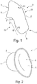
- Figure 1 shows a side view of an otoplastic 1 for hearing aids. Due to the schematic view, only the outer contours of the otoplastic 1, which is hollow per se and is made of a flexible or semi-flexible silicone material, are shown.
- the otoplastic 1 consists in one piece of a base body 2 which tapers from a connection side 3 to an auditory canal side 4. On the connection side 3, a first opening 5 is provided, which is used to connect a hearing aid accessory such as one in Figure 7 shown sound tube 17 is used.
- the base body 2 has a connection section 7 toward the connection side 3, which is intended for insertion of the hearing aid accessories.
- the base body Towards the auditory canal side 4, the base body has an auditory canal section 8, which is used, for example, for sound transmission or for protecting a sound tube 17 guided through the otoplastic 1 to a second opening 6, the sound outlet opening.
- a concave curvature section 9 is provided between the connection section 7 and the auditory canal section 8 at least on part of the circumference of the otoplastic 1.
- This transition between the connection section 7 and the auditory canal section 8 creates a kind of "kink" in which the main direction of extension extends of the base body 2 changes at least slightly.
- the concave curvature section 9 defines the insertion depth and the insertion angle of a hearing aid accessory inserted into the otoplastic 1 and prevents it from protruding too far into the auditory canal section 8. At the same time, it is not a sharp, but gradual change of direction that significantly reduces the notch effect of the transition.
- the concave curvature section 9 is located on a front side 11 of the otoplastic 1, which would point towards the center of the head of the hearing device wearer when the otoplastic 1 is inserted into an ear.
- the connection section 7 merges into the auditory canal section 8 via a convex curved section 13.
- the radius of curvature r 2 of the convex curvature section 13 on the rear side 12 is preferably greater than the radius of curvature r 1 of the concave curvature section 9 on the front side 11 of the base body 2. This flatter, softer transition means that the connection section 7 on the rear side 12 is more easily deformable elastically, making it easier to insert hearing aid accessories.
- the radius of curvature r 2 can, for example, have a radius of curvature of 15 mm in the initial state, that is to say without any accessories being introduced.
- the radius of curvature r 1 is significantly smaller and is, for example, 3 mm.
- the earmold 1 in Figure 1 has in the auditory canal section 8 towards the auditory canal side 4 a convex curvature section 10 which adjoins the concave curvature section 9.
- the convex curvature section 10 can be made just as wide as the concave curvature section 9, but it can also be wider or narrower, and in particular can also be made over the entire circumference of the base body 2 in the auditory canal section 8.
- the convex curvature section 10 enables an improved hold of the otoplastic 1 in the ear of the hearing device wearer, since the bulge can contact adjacent inner ear structures.
- Figure 2 shows a schematic plan view of the connection side 3 of the otoplastic 1.
- the oval contour of the first opening 5 is clearly shown; of the "kink" or change of direction of the base body 2 in the concave curvature section 9, a part of the auditory canal section 8 can still be seen.
- the base body 2 has an oval cross section over its entire longitudinal extent, in which the front side 11 and the rear side 12 form the longer oval long sides and the intermediate side areas can be assigned to the shorter oval broad sides.
- an inserted sound tube 17 or other hearing aid accessories can be held reliably regardless of its size or shape, because there are strong resilience and therefore contact forces on one side of the oval Form elastic deformation through the hearing aid accessories.
- FIGS 3 and 4 top views of the front sides 11 of two different embodiments of the otoplastic 1 are shown schematically.
- the otoplastic 1 in Figure 4 a collar 14 protruding inward into the first opening 5, which represents a material reinforcement of the base body 2 at the first opening 5 and thus improves the fixation of an inserted hearing aid accessory.
- the connection section 7 and the auditory canal section 8 can again be seen, which merge into one another at least on a part of the circumference of the base body 2 via the concave curvature region 9 shown with hatching.
- Figure 5 shows a schematic top view of the auditory canal side 4 of the otoplastic 1.
- the second opening 6 can be clearly seen, which can serve as a sound outlet opening and / or for receiving a sound tube 17.
- the diameter of the second opening 6, if it is intended as a receptacle for a sound tube 17, can either be designed for standard sound tubes and be, for example, 3 mm, or also be designed for receiver-in-canal or thin tube systems and thus be, for example, 2 mm.
- a ventilation opening 16 Adjacent to the second opening 6 is a ventilation opening 16, which allows ventilation of the inside of the hearing aid wearer through the otoplastic 1 and thus pressure equalization, so that the wearing comfort of the otoplastic 1 is significantly increased.
- Figure 6 shows a top view of the back 12 of the otoplastic 1 and, in particular, in a transparent section on the auditory canal side 4, the bores for the second opening 6 and the ventilation opening 16
- the ear canal section 8 is provided by increasing the wall thickness of the base body 2 in this area compared to the wall thickness of the further base body 2.
- the material reinforcement 15 takes place inwards into the cavity of the otoplastic 1.
- the second opening 6 and the ventilation opening 16 are drilled, the length of which corresponds to the wall thickness of the material reinforcement 15 and can be, for example, 3 mm.
- a sound tube 17 received by the second opening 6 is held particularly securely by the material reinforcement 15 and is stabilized against external forces and moments.
- Figure 7 shows a transparent side view of the otoplastic 1 with an inserted sound tube 17.
- the connector 18 is inserted through the first opening 5 into the connector section 7 of the base body 2, the otoplastic 1 elastically expanding around the connector 18 and at least at the connector 18 the long sides of the oval.
- the connection 18 is connected to a hearing device (not shown) and forwards sound signals generated by it via the sound tube 17.
- the sound tube 17 is guided through the otoplastic 1 to the second opening 6, which forms a receptacle for the end of the sound tube 17.
- the transmitted sound emerges from this end of the sound tube 17, so that the opening 6 also represents a sound outlet opening.
- hearing aid accessories can also be connected to the otoplastic 1 shown, since, owing to the oval first opening 5 in connection with the concave curvature section 9, they accommodate and securely accommodate a large number of connector, cable, receiver, speaker or tube shapes and sizes can hold.
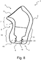
- FIG 8 shows a sectional view through an embodiment of an otoplastic 1 with retaining ribs 19 in the second opening 6 on the auditory canal side 4.
- the earmold 1 is adapted for universal reception of different sound tubes by a plurality of holding ribs 19 arranged one behind the other in the insertion direction of a sound tube or in the longitudinal direction of the second opening 6.
- These holding ribs 19 in the interior of the second opening 6 partially reduce the inside diameter of the second opening 6 in order to thereby fix a sound tube to the otoplastic 1 by means of the elastic deformation of the holding ribs 17 in the second opening 6.
- the retaining ribs 19 are formed on the end region of the earmold 1 on the auditory canal side 4 which is less elastic than the connection side 3 and is formed by a material reinforcement 15.
- the end of the sound tube which may also be a receiver end (“ receiver -in channel”), also has circumferential grooves or retaining ribs or lamellae, the end of the sound tube can be held on the earmold 1 not only by frictional engagement, but also by a form shot become.
- the second opening 6 can have a plurality of conical sections 20 arranged one behind the other, each of which forms a section with a conically tapering diameter of the second opening 6, the diameter of the conical section 20 following the opening of a previous section 20 following each of the preceding section 20 is larger than the diameter of the mouth of the preceding section 20.
- elastic retaining ribs 19 which are sufficiently dimensionally stable for fixing different sound hoses 17 are formed.
Abstract
Die Erfindung betrifft eine einstückig ausgeführte, flexible oder semiflexible Otoplastik (1) als Ohreinsatz für Hörgeräte. Die Otoplastik (1) hat einen hohlen, schlauchartigen Grundkörper (2), der sich von einer Anschlussseite (3) zu einer Gehörgangsseite (4) hin verjüngt. An der Anschlussseite (3) ist eine erste Öffnung (5) zum Anschluss eines Hörgerätezubehörs und an der Gehörgangsseite (4) eine zweite Öffnung (6) für einen Schallaustritt und/oder als Aufnahme für das Ende eines Schallschlauchs (17) vorgesehen. Die erste Öffnung (5) an der Anschlussseite (3) weist eine ovale Kontur auf. Außerdem geht ein der Anschlussseite (3) zugeordneter Anschlussabschnitt (7) des Grundkörpers (2) über einen konkaven Krümmungsabschnitt (9) in einen der Gehörgangsseite (4) zugeordneten Gehörgangsabschnitt (8) des Grundkörpers (2) über. Bei der erfindungsgemäßen Otoplastik (1) handelt es sich um eine Universalotoplastik, die anatomisch so geformt ist, dass sie von einer Vielzahl von Personen mit einer hohen Passgenauigkeit und einem hohen Tragekomfort benutzt werden kann. Zugleich handelt es sich um eine Universalotoplastik, die einteilig ausgeführt ist und ohne jegliche Adapter mit einer Vielzahl von Gerätetypen und -modellen verbunden werden kann, da sie durch ihre spezielle Form im Anschlussabschnitt (7) mit unterschiedlichen Hörgerätezubehörteilen koppelbar ist. Die Erfindung betrifft auch eine Verwendung einer solchen Otoplastik (1) als Probeotoplastik zum Testen verschiedener Hörgerätetypen und Hörgerätemodelle.The invention relates to a one-piece, flexible or semi-flexible earmold (1) as an ear insert for hearing aids. The otoplastic (1) has a hollow, tubular base body (2) that tapers from a connection side (3) to an auditory canal side (4). A first opening (5) for connecting a hearing aid accessory is provided on the connection side (3) and a second opening (6) for sound exit and / or as a receptacle for the end of a sound tube (17) is provided on the auditory canal side (4). The first opening (5) on the connection side (3) has an oval contour. In addition, a connection section (7) of the base body (2) assigned to the connection side (3) merges via a concave curvature section (9) into an auditory canal section (8) of the base body (2) assigned to the auditory canal side (4). The otoplastic (1) according to the invention is a universal otoplastic that is anatomically shaped so that it can be used by a large number of people with a high degree of accuracy and comfort. At the same time, it is a universal earmold that is made in one piece and can be connected to a variety of device types and models without any adapters, since its special shape in the connection section (7) enables it to be coupled with different hearing aid accessories. The invention also relates to the use of such an otoplastic (1) as a trial otoplastic for testing different types of hearing aids and hearing aid models.
Description
Die Erfindung betrifft eine einstückige, flexible oder semiflexible Otoplastik als Ohreinsatz für Hörgeräte mit einem hohlen, schlauchartigen Grundkörper, der sich von einer Anschlussseite zu einer Gehörgangsseite hin verjüngt, wobei an der Anschlussseite eine erste Öffnung zum Anschluss eines Hörgerätezubehörs und an der Gehörgangsseite eine zweite Öffnung für einen Schallaustritt und/oder als Aufnahme für das Ende eines Schallschlauchs vorgesehen ist.The invention relates to a one-piece, flexible or semi-flexible earmold as an ear insert for hearing aids with a hollow, tubular body that tapers from a connection side to an auditory canal side, with a first opening on the connection side for connecting hearing aid accessories and a second opening on the auditory canal side is provided for a sound outlet and / or as a receptacle for the end of a sound tube.
Solche Otoplastiken bilden den in das Ohr eines Hörgeräteträgers eingeführten Teil eines Hörgerätes bzw. einer Hörhilfe und dienen dazu, mit dem Hörgerät erzeugte bzw. verstärkte Schallsignale an das Innenohr des Hörgeräteträgers weiterzuleiten. Hierzu wird die Otoplastik direkt mit einem Lautsprecher oder einem sogenannten Schallschlauch verbunden, der auf der anderen Seite mit dem Hörgerät gekoppelt ist und seinerseits der Schallübertragung dient. Üblicherweise wird für einen langfristigen Einsatz einer Otoplastik diese passgenau und individuell durch Abbilden einer Negativkontur über eine Ohr- und Gehörgangsabformung hergestellt.Such otoplastics form the part of a hearing aid or a hearing aid inserted into the ear of a hearing aid wearer and serve to pass on sound signals generated or amplified with the hearing aid to the inner ear of the hearing aid wearer. For this purpose, the earmold is connected directly to a loudspeaker or a so-called sound tube, which is coupled to the hearing aid on the other side and in turn is used for sound transmission. Usually, for long-term use of an otoplastic, it is manufactured precisely and individually by imaging a negative contour via an ear and auditory canal impression.
Da jedoch nicht nur die Ohrformen und -größen der Hörgeräteträger, sondern auch die erhältlichen Hörgerätetypen und -modelle stark variieren, bestehen Bestrebungen, die Kompatibilität von Otoplastiken mit unterschiedlichen Geräten zu erhöhen.However, since not only the ear shapes and sizes of the hearing device wearers vary greatly, but also the types and models of hearing devices available, efforts are being made to increase the compatibility of earmolds with different devices.
Die
In der
Die
Der
In der
Ausgehend hiervon ist es Aufgabe der vorliegenden Erfindung, eine verbesserte Otoplastik mit einem erhöhten Bedienungs- und Tragekomfort bei gleichzeitiger Kompatibilität mit unterschiedlichen Ohrformen und Hörgeräten bereitzustellen.Proceeding from this, it is an object of the present invention to provide an improved otoplastic with an increased ease of use and wearing while being compatible with different ear shapes and hearing aids.
Die Aufgabe wird durch die Otoplastik mit den Merkmalen des Anspruchs 1 gelöst. Vorteilhafte Ausführungsformen sind in den Unteransprüchen beschrieben.The object is achieved by the otoplastic with the features of
Demnach ist eine einstückige, flexible oder semiflexible Otoplastik als Ohreinsatz für Hörgeräte vorgesehen. Unter einer flexiblen Otoplastik wird eine Otoplastik verstanden, die haptisch deutlich spürbar biegsam und elastisch ist, jedoch bei Rücknahme einer beaufschlagten Krafteinwirkung in ihre vorherige Form zurückkehrt. Bei einer semiflexiblen Otoplastik ist dieser haptische Eindruck einer Elastizität deutlich geringer, aber immer noch vorhanden, und das Otoplastikmaterial bietet einen spürbaren Widerstand gegenüber einer elastischen Verformung, lässt diese aber dennoch zu. Die Flexibilität kann auch entlang der Otoplastik variieren, beispielsweise kann diese einen flexiblen Anschlussabschnitt für einen einfacheren Anschluss eines Schallschlauchs oder Lautsprechers und einen semiflexiblen Gehörgangsabschnitt für einen verbesserten Halt der Otoplastik im Ohr aufweisen.Accordingly, a one-piece, flexible or semi-flexible earmold is provided as an ear insert for hearing aids. A flexible otoplastic is understood to be an otoplastic which is clearly noticeably flexible and elastic, but which returns to its previous shape when an applied force is withdrawn. With a semi-flexible earmold, this haptic impression of elasticity is significantly less, but is still there, and the earmold material offers a noticeable resistance to elastic deformation, but still allows it. The flexibility can also vary along the otoplastic, for example it can have a flexible connection section for easier connection of a sound tube or loudspeaker and a semi-flexible ear canal section for an improved hold of the otoplastic in the ear.
Die Otoplastik hat einen hohlen, schlauchartigen Grundkörper und bildet somit einen im Wesentlichen runden Hohlkörper, vorzugsweise ohne scharfe Ecken oder Kanten an der Außenseite. Der den Hohlraum umgebende Mantel des Grundkörpers ist hierbei je nach Flexibilitätsgrad (flexibel oder semiflexibel) stärker oder schwächer elastisch verformbar.The otoplastic has a hollow, tubular base body and thus forms an essentially round hollow body, preferably without sharp corners or edges on the outside. Depending on the degree of flexibility (flexible or semi-flexible), the shell of the base body surrounding the cavity can be elastically deformed to a greater or lesser extent.
Der Grundkörper verjüngt sich von einer Anschlussseite zu einer Gehörgangsseite hin, wobei die Verjüngung zumindest abschnittsweise konisch sein kann. Mit der Verjüngung verringert sich der Durchmesser der Otoplastik und ihr Querschnitt wird kleiner von einer Anschlussseite in Richtung der Gehörgangsseite gesehen.The base body tapers from a connection side to an auditory canal side, the tapering being conical, at least in sections. The taper reduces the diameter of the otoplastic and its cross-section is seen smaller from a connection side in the direction of the ear canal side.
Als Anschlussseite wird die Seite der Otoplastik bezeichnet, an der ein Hörgerätezubehör angeschlossen wird, beispielsweise ein Lautsprecher, Schallschlauch, Stecker oder Kabel in die Otoplastik eingeführt wird. Im Falle eines Schallschlauchs wird dieser von der Anschlussseite aus weiter durch die Otoplastik hindurchgeführt und endet schließlich an der Gehörgangsseite, wo er beispielsweise in eine Schallaustrittsöffnung der Otoplastik auf der Gehörgangsseite eingesteckt wird und von hier aus Schallsignale in das Ohrinnere des Hörgeräteträgers abgibt. Im Falle beispielsweise eines Lautsprechers, der an der Anschlussseite der Otoplastik angeordnet wird, können sich die hierüber abgegebenen Schallsignale im Inneren der Otoplastik in Richtung Gehörgangsseite ausbreiten und treten dort schließlich aus einer Schallaustrittsöffnung der Otoplastik auf der Gehörgangsseite aus. An der Gehörgangsseite austretender Schall kann somit in den Gehörgang des Hörgeräteträgers eintreten und von dort aus die weiteren Hörorgane wie beispielsweise das Innenohr erreichen.The connection side is the side of the otoplastic to which a hearing aid accessory is connected, for example a loudspeaker, sound tube, plug or cable is inserted into the otoplastic. In the case of a sound tube, this is passed from the connection side further through the otoplastic and finally ends on the auditory canal side, where it is inserted, for example, into a sound outlet opening of the otoplastic on the auditory canal side and emits sound signals from here into the inside of the hearing aid wearer. In the case of, for example, a loudspeaker which is arranged on the connection side of the earmold, the sound signals emitted via this can spread inside the earmold towards the ear canal side and finally exit there from a sound outlet opening of the earmold on the ear canal side. Sound emerging on the auditory canal side can thus enter the auditory canal of the hearing device wearer and from there reach the further hearing organs, such as the inner ear.
Somit ist an der Anschlussseite eine erste Öffnung zum Anschluss eines Schallschlauchs oder Lautsprechers vorgesehen, während an der Gehörgangsseite eine zweite Öffnung für einen Schallaustritt vorgesehen ist, die als universelle Aufnahme für das Ende eines Schallschlauchs ausgebildet ist.Thus, a first opening for connecting a sound tube or loudspeaker is provided on the connection side, while a second opening for a sound outlet is provided on the auditory canal side, which is designed as a universal receptacle for the end of a sound tube.
Die erste Öffnung an der Anschlussseite weist eine ovale Kontur auf. Unter einer ovalen Kontur wird eine Kontur verstanden, die von einer kreisrunden Kontur abweicht. Insbesondere wird unter einer ovalen Kontur eine eher langgestreckte, beispielsweise elliptische und somit symmetrische oder auch eine an einer oder zwei Seiten spitz zulaufende Kontur verstanden.The first opening on the connection side has an oval contour. An oval contour is understood to mean a contour that deviates from a circular contour. In particular, an oval contour is understood to mean a rather elongated, for example elliptical and thus symmetrical, or also a tapering shape on one or two sides.
Der Anschlussseite der Otoplastik ist ein Anschlussabschnitt des Grundkörpers zugeordnet, der sich von der ersten Öffnung ausgehend in Richtung der Gehörgangsseite erstreckt und über einen konkaven Krümmungsabschnitt in einen Gehörgangsabschnitt übergeht, der der Gehörgangsseite zugeordnet ist. Somit weist der Grundkörper zwischen dem Anschlussabschnitt und dem Gehörgangsabschnitt einen konkaven Krümmungsabschnitt auf. Dieser kann teilumfänglich an der Otoplastik vorgesehen sein oder es kann über den gesamten Umfang des Grundkörpers ein konkaver Krümmungsabschnitt zwischen Anschlussabschnitt und Gehörgangsabschnitt gebildet sein.The connection side of the otoplastic is assigned a connection section of the base body, which extends from the first opening in the direction of the auditory canal side and merges via a concave curvature section into an auditory canal section which is assigned to the auditory canal side. The base body thus has a concave curvature section between the connection section and the auditory canal section. This can be partially provided on the earmold or a concave curvature section can be formed between the connection section and the auditory canal section over the entire circumference of the base body.
Unter einem konkaven Krümmungsabschnitt wird eine bogenförmige Kontur mit einem optisch wahrnehmbaren Radius verstanden. Die Rundung des Krümmungsabschnitts ist mit bloßem Auge erkennbar. Der Anschlussabschnitt geht somit unter einem runden Absatz mit einem Innenradius in den Gehörgangsabschnitt über. Bei einem teilumfänglichen Krümmungsabschnitt ist dieser aus seitlichen Ansichten der Otoplastik als "Knick" wahrnehmbar, da sich durch den Krümmungsabschnitt die Haupterstreckungsrichtung des Grundkörpers leicht ändert. Dies bedeutet, dass der Anschlussabschnitt und der Gehörgangsabschnitt nicht gerade ineinander übergehen, sondern gewissermaßen in einem Winkel aufeinander stehen.A concave curvature section is understood to mean an arcuate contour with an optically perceptible radius. The curve of the curvature section can be seen with the naked eye. The connecting section thus merges into the auditory canal section under a round shoulder with an inner radius. In the case of a partially circumferential curvature section, this can be perceived as a “kink” from side views of the otoplastic, since the main extension direction of the base body changes slightly due to the curvature section. This means that the connecting section and the auditory canal section do not merge into one another, but rather are at an angle to one another.
Eine derart geformte Otoplastik bietet eine universelle Anschlussmöglichkeit für eine Vielzahl unterschiedlicher Hörgeräteanschlüsse wie Stecker, Lautsprecher, Schallschläuche und Kabel in verschiedenen Formen und Größen. Durch seine (Semi-)Flexibilität ist der Grundkörper, insbesondere der Anschlussabschnitt des Grundkörpers ausreichend elastisch, um sich beim Einstecken eines Hörgerätezubehörs entsprechend der Form und Größe des Zubehörs zu verformen und an dieses anzulegen. Hierbei ist insbesondere die längliche ovale Form der ersten Öffnung von Vorteil, da diese höhere Rückfeder- und Anpresskräfte an den längeren Ovalseiten ausbildet und somit das eingesteckte Zubehör unabhängig von dessen Form und Größe besser fixieren kann als eine kreisrunde Öffnung mit gleichmäßig am Umfang verteilter Kraftwirkung, die eine ähnliche Form und Größe des eingesteckten Zubehörs voraussetzt.Such shaped earmold offers a universal connection option for a variety of different hearing aid connections such as plugs, speakers, sound tubes and cables in various shapes and sizes. Due to its (semi) flexibility, the base body, in particular the connecting section of the base body, is sufficiently elastic to deform and to fit on the accessory when it is inserted, in accordance with the shape and size of the accessory. Here, the elongated oval shape of the first opening is particularly advantageous, since it forms higher spring-back and contact forces on the longer oval sides and can therefore fix the inserted accessories better regardless of their shape and size than a circular opening with a force effect evenly distributed around the circumference, which requires a similar shape and size of the inserted accessories.
Der konkave Krümmungsabschnitt definiert und begrenzt die Einführtiefe und den Einführwinkel des in die Otoplastik eingesteckten Hörgerätezubehörs. Bei einem teilumfänglich ausgeführten konkaven Krümmungsabschnitt, bildlich mit dem oben beschriebenen "Knick" in der Otoplastik vergleichbar, ergibt sich zudem ein verbesserter Tragekomfort und Halt der Otoplastik im Ohr des Hörgeräteträgers, da gerade Otoplastiken leichter aus dem Ohr herausrutschen können.The concave curvature section defines and limits the insertion depth and the insertion angle of the hearing aid accessories inserted into the otoplastic. In the case of a partially concave section of curvature, visually comparable to the "kink" described above in the otoplastic, there is also improved wearing comfort and retention of the otoplastic in the ear of the hearing device wearer, since otoplastics in particular can slide out of the ear more easily.
Bei der erfindungsgemäßen Otoplastik handelt es sich um eine Universalotoplastik, die anatomisch so geformt ist, dass sie von einer Vielzahl von Personen mit einer hohen Passgenauigkeit und einem hohen Tragekomfort benutzt werden kann. Zugleich handelt es sich um eine Universalotoplastik, die einteilig ausgeführt ist und ohne jegliche Adapter mit einer Vielzahl von Gerätetypen und -modellen verbunden werden kann, da sie durch ihre spezielle Form im Anschlussbereich mit unterschiedlichen Hörgerätezubehörteilen koppelbar ist.The otoplastic according to the invention is a universal otoplastic that is anatomically shaped so that it can be used by a large number of people with a high degree of accuracy and comfort. At the same time it is a universal earmold, which is made in one piece and can be connected to a variety of device types and models without any adapters, since it can be coupled with different hearing aid accessories due to its special shape in the connection area.
Somit können mit einer universellen Otoplastiklösung diversen hörbeeinträchtigten Personen beispielsweise in einer Erprobungsphase verschiedene Hörlösungen angeboten werden. Zudem kann einem Interessenten sofort, beispielsweise bei einer Erstberatung, eine Hörlösung zur Verfügung gestellt werden, da die bisher übliche Anfertigung einer Individualotoplastik entfällt. Somit entfällt auch eine zeitaufwendige individuelle Anpassung der Otoplastik oder wird zumindest beschleunigt. Diese Vorteile gelten nicht nur für den Interessenten oder Kunden, sondern auch für Hörgeräte anbietende und herstellende Unternehmen, für die die mit Kosten und Aufwand verbundene Anfertigung von Individualotoplastiken zumindest während der Erprobungsphase entfällt.Thus, with a universal otoplastic solution, various hearing impaired people can be offered various hearing solutions, for example in a trial phase. In addition, a hearing solution can be made available to a prospective customer immediately, for example during initial consultation, since the customary preparation of an individual earmould is no longer required. This also eliminates the time-consuming individual adaptation of the otoplastic or at least speeds it up. These advantages apply not only to prospective customers or customers, but also to companies that offer and manufacture hearing aids, for which the cost and effort involved in manufacturing individual earmoulds is eliminated, at least during the trial phase.
Die Otoplastik weist entlang ihres gesamten Grundkörpers einen ovalen Querschnitt auf. Somit ist nicht nur die Anschlussöffnung oval, sondern die gesamte Otoplastik von der Anschlussseite bis zur Gehörgangsseite. Durch diese Form und die elastische Verformbarkeit passt sich die Otoplastik insbesondere entlang ihrer längeren Ovallängsseiten besser an den Gehörgang an und bietet mehr Stabilität als kreisrunde Otoplastikquerschnitte.The otoplastic has an oval cross section along its entire base body. This means that not only is the connection opening oval, but the entire earmold from the connection side to the ear canal side. Due to this shape and the elastic deformability, the earmold adapts better to the ear canal, especially along its longer oval sides, and offers more stability than circular earmold cross sections.
Die Otoplastik hat bevorzugt nicht einfach einen sich von der Anschlussöffnung über den Anschlussabschnitt und den Gehörgangsabschnitt bis zur Gehörgangsseite hin verjüngenden Querschnitt bzw. Außenumfang. Vorteilhaft ist es, wenn sich an den konkaven Krümmungsabschnitt ein konvexer Krümmungsabschnitt im Gehörgangsabschnitt zur Gehörgangsseite hin anschließt. Somit folgen unterhalb des Anschlussabschnitts zwei entgegengesetzte Krümmungen aufeinander. In einer seitlichen Ansicht ergibt sich hiermit eine S-Kontur der Otoplastik über einen Teil der Otoplastik. Eine solche Otoplastik zeichnet sich durch einen besseren Sitz im Gehörgang aus, weil sich der konvexe Krümmungsabschnitt im Gehörgangsabschnitt weich an den Gehörgang des Hörgeräteträgers anlegt. Der Verlauf des Außenumfangs der Otoplastik von der Anschlussöffnung über den Anschlussabschnitt und den Gehörgangsabschnitt bis zur Gehörgangsseite ist an die gemittelte Anatomie der Gehörgänge einer Vielzahl von Nutzern angepasst. Damit bietet die Otoplastik für den Großteil der Patienten einen ausreichenden Halt, auch wenn die Otoplastik nicht genau an die Gehörgangs-Anatomie des individuellen Patienten angepasst ist.The otoplastic preferably does not simply have a cross section or outer circumference that tapers from the connection opening via the connection section and the auditory canal section to the auditory canal side. It is advantageous if the concave curvature section is followed by a convex curvature section in the auditory canal section towards the auditory canal side. Thus, two opposite curvatures follow one another below the connection section. In a side view, this results in an S contour of the otoplastic over part of the otoplastic. Such an otoplastic is characterized by a better fit in the auditory canal because the convex curvature section in the auditory canal section lies softly against the auditory canal of the hearing device wearer. The course of the outer circumference of the otoplastic from the connection opening via the connection section and the auditory canal section to the auditory canal side, a large number of users are adapted to the averaged anatomy of the auditory canals. As a result, the otoplastic provides sufficient support for the majority of patients, even if the otoplastic is not exactly adapted to the individual patient's ear canal anatomy.
Der Krümmungsradius des konkaven Krümmungsabschnitts kann zwischen 1 und 5 mm betragen. Bevorzugt ist es, wenn der Krümmungsradius zwischen 2 und 4 mm beträgt. In diesem besonders günstigen Radiusbereich wird angeschlossenes Hörgerätezubehör zuverlässig fixiert, ohne dass der Absatz ein unangenehmes Tragegefühl oder eine materialschwächende Kerbwirkung erzeugt.The radius of curvature of the concave curvature section can be between 1 and 5 mm. It is preferred if the radius of curvature is between 2 and 4 mm. Connected hearing aid accessories are reliably fixed in this particularly favorable radius range without the heel creating an uncomfortable wearing comfort or a material-weakening notch effect.
Der Anschlussabschnitt geht an einer Vorderseite der Otoplastik unter einem konkaven Krümmungsabschnitt und an einer gegenüberliegenden Rückseite unter einem konvexen Krümmungsabschnitt in den Gehörgangsabschnitt über, wobei der Krümmungsradius des konkaven Krümmungsabschnitts an der Vorderseite kleiner ist als der Krümmungsradius des konvexen Krümmungsabschnitts an der Rückseite. Als Vorderseite wird der Bereich der Otoplastik angesehen, der bei einem Einführen der Otoplastik nach innen in Richtung der Kopfmitte des Hörgeräteträgers zeigen würde. Als Rückseite ist entsprechend die der Vorderseite gegenüberliegende Seite der Otoplastik anzusehen, die in einem eingeführten Zustand nach außen und vom Kopf weg zeigen würde. Die Vorder- und die Rückseite erstrecken sich jeweils von den längeren Längsseiten des Ovals der ersten Öffnung in Richtung Gehörgangsseite. Bei der Ausführungsform mit einem stärker gekrümmten konkaven Krümmungsabschnitt an der Vorderseite und einem schwächer gekrümmten konvexen Krümmungsabschnitt an der Rückseite ist der Übergang des Anschlussabschnitts in den Gehörgangsabschnitt auf der Rückseite flacher und weniger stark gebogen als auf der gegenüberliegenden "Knick"-Seite. Hierdurch können die Einführtiefe und der Einführwinkel des eingesteckten Hörgerätezubehörs in Grenzen leicht variiert werden, sodass die Kompatibilität gegenüber unterschiedlichen Zubehörtypen erhöht wird. Zudem ist der flachere Krümmungsabschnitt auf der Rückseite leichter elastisch verformbar, sodass das Einführen eines Hörgerätezubehörs erleichtert wird. Der konvexe Krümmungsabschnitt auf der Rückseite kann im Ausgangszustand, also ohne eingeführtes Zubehör, beispielsweise einen Krümmungsradius zwischen 10 und 20 mm aufweisen. In diesem Radiusbereich liegt eine verbesserte Biegsamkeit des Anschlussabschnitts an der Rückseite der Otoplastik vor.The connection section merges with the concave curved section on a front side of the otoplastic and the auditory canal section under the convex curved section on an opposite rear side, the radius of curvature of the concave curved section on the front being smaller than the radius of curvature of the convex curved section on the rear side. The area of the otoplastic, which would point inwards towards the center of the head of the hearing aid wearer when the otoplastic is inserted, is regarded as the front. Correspondingly, the back of the side of the earmold opposite the front should be viewed, which in an inserted state would point outwards and away from the head. The front and the back each extend from the longer long sides of the oval of the first opening towards the ear canal side. In the embodiment with a more curved concave curvature section on the front and a less curved convex curvature section on the back, the transition of the connection section into the auditory canal section on the back is flatter and less bent than on the opposite "kink" side. As a result, the insertion depth and the insertion angle of the inserted hearing aid accessories can be varied slightly within limits, so that the compatibility with different types of accessories is increased. In addition, the flatter curvature section on the back is easier to deform elastically, so that the insertion of hearing aid accessories is made easier. The convex curvature section on the back can, for example, have a radius of curvature between 10 and 20 in the initial state, that is to say without any accessories being introduced mm. In this radius area there is an improved flexibility of the connection section on the back of the otoplastic.
Es hat sich als vorteilhaft erwiesen, wenn an der Anschlussseite der Otoplastik an den Anschlussabschnitt ein in die erste Öffnung ragender Kragen angeformt ist. Es handelt sich hierbei um einen leicht nach innen gebogenen oder gestülpten Rand der Otoplastik an der Anschlussseite. Ein solcher Kragen bildet eine Materialverstärkung am Umfang der ersten Öffnung und unterstützt die Anpressung des Anschlussabschnitts an ein eingeführtes Zubehör.It has proven to be advantageous if a collar protruding into the first opening is formed on the connection side of the otoplastic. This is a slightly inwardly bent or inverted edge of the earmold on the connection side. Such a collar forms a material reinforcement on the circumference of the first opening and supports the pressing of the connection section against an inserted accessory.
In einer vorteilhaften Ausführungsform ist die die zweite Öffnung der Otoplastik an der Gehörgangsseite als Aufnahme für Receiver-In-Canal- oder Dünnschlauchsysteme ausgebildet. In diesem Sinne ist die zweite Öffnung als eine Bohrung in dem Otoplastikmantel mit einer vordefinierten Länge und einem vordefinierten Durchmesser ausgebildet, um die Schallschläuche eines Receiver-In-Canal- oder Dünnschlauchsystems aufnehmen zu können, die wesentlich kleiner sind als beispielsweise die von Standardschallschläuchen. Zudem kann der Grundkörper am Umfang der zweiten Öffnung mit Halterippen (bspw. in Form von umlaufenden Lamellen an der Innenwand der zweiten Öffnung) verstärkt sein, um das eingesteckte Zubehör insbesondere im Falle der besonders schmalen Anschlüsse von Receiver-In-Canal- und Dünnschlauchsystemen zuverlässig und sicher zu fixieren. Der Bohrungsdurchmesser kann in diesem Beispiel zwischen 0,5 und 1,5 mm betragen. Für Standardschallschläuche ist die Bohrung hingegen breiter ausgeführt und beträgt beispielsweise zwischen 1,5 und 2,5 mm. Die Länge der Bohrung kann in beiden Fällen bevorzugt zwischen 2 und 4 mm betragen.In an advantageous embodiment, the second opening of the otoplastic on the ear canal side is designed as a receptacle for receiver-in-canal or thin tube systems. In this sense, the second opening is designed as a bore in the otoplastic jacket with a predefined length and a predefined diameter in order to be able to accommodate the sound tubes of a receiver-in-canal or thin tube system, which are significantly smaller than, for example, those of standard sound tubes. In addition, the base body on the circumference of the second opening can be reinforced with retaining ribs (for example in the form of circumferential lamellae on the inner wall of the second opening) in order to reliably insert the accessories inserted, in particular in the case of the particularly narrow connections of receiver-in-canal and thin hose systems and fix it securely. The bore diameter in this example can be between 0.5 and 1.5 mm. The bore for standard sound hoses, on the other hand, is wider and is, for example, between 1.5 and 2.5 mm. The length of the hole can preferably be between 2 and 4 mm in both cases.
Günstig ist es, wenn die Wandstärke der Otoplastik in einem der Gehörgangsseite zugeordneten Bereich gegenüber dem weiteren Grundkörper erhöht ist. Somit ist die Otoplastik an ihrem der Gehörgangsseite zugeordneten Ende dicker als in anderen Bereichen der Otoplastik, wobei die Materialverdickung nach innen in den Hohlraum ausgeführt ist. Hierdurch kann ein von der zweiten Öffnung aufgenommener Schallschlauch zuverlässig fixiert und besser gegen ein Herausrutschen gesichert werden.It is expedient if the wall thickness of the otoplastic is increased in an area assigned to the auditory canal side compared to the further base body. Thus, the otoplastic at its end assigned to the side of the ear canal is thicker than in other areas of the otoplastic, the material thickening being carried out inwards into the cavity. In this way, a sound tube received by the second opening can be reliably fixed and better secured against slipping out.
Bevorzugt ist auf der Gehörgangsseite der Otoplastik neben der zweiten Öffnung eine weitere Belüftungsöffnung vorgesehen. Diese wird nicht durch ein eingeführtes Zubehör geschlossen, sondern bleibt auch im getragenen Zustand der Otoplastik stets offen. Somit ermöglicht diese Belüftungsöffnung einen Druckausgleich des Ohrinneren und erhöht damit den Tragekomfort der Otoplastik.A further ventilation opening is preferably provided on the ear canal side of the otoplastic in addition to the second opening. This is not closed by an introduced accessory, but remains open even when the earmold is worn. This ventilation opening allows pressure equalization of the inside of the ear and thus increases the comfort of the earmold.
Die Otoplastik kann aus einem Silikonmaterial hergestellt sein. Dieses bietet günstige elastische Eigenschaften, die die nötige Anpresskraft der Otoplastik an ein Hörgerätezubehör und an das Ohr des Hörgeräteträgers bereitstellen. Zudem sind Silikonmaterialien hygienisch und aufgrund ihrer Oberflächenstruktur angenehm zu tragen. Somit kann einem Interessenten sofort, beispielsweise bei einer Erstberatung, eine spontan verträgliche Universalotoplastik zur Verfügung gestellt werden.The earmold can be made from a silicone material. This offers favorable elastic properties that provide the necessary contact pressure of the earmold on a hearing aid accessory and on the ear of the hearing aid wearer. In addition, silicone materials are hygienic and comfortable to wear due to their surface structure. This means that a prospective customer can immediately be provided with a spontaneously compatible universal otoplastic, for example during an initial consultation.
In einer bevorzugten Ausführungsform ist die Otoplastik aus einem transparenten Material hergestellt. Hierdurch wird eine vereinfachte optische Überprüfung des korrekten Sitzes von eingeführtem Hörgerätezubehör und eine optische Prüfung auf innere Beschädigungen oder Verunreinigungen der Otoplastik ermöglicht.In a preferred embodiment, the otoplastic is made from a transparent material. This enables a simplified visual check of the correct fit of the inserted hearing aid accessories and a visual check for internal damage or contamination of the otoplastic.
Die Erfindung betrifft auch eine Verwendung einer Otoplastik nach den vorbeschriebenen Merkmalen als Probeotoplastik zum Testen verschiedener Hörgerätetypen und Hörgerätemodelle. Eine solche Probeotoplastik kann ohne weitere Adapter mit unterschiedlichem Zubehör, beispielsweise verschiedenen Schallschläuchen oder Lautsprechern verbunden werden und ist somit insbesondere für Testphasen besonders geeignet. Zugleich ist die Probeotoplastik derart anatomisch geformt, dass sie als Fertigotoplastik ohne individuelle Anpassung von einer Vielzahl unterschiedlicher Personen verwendet werden kann. Hierdurch wird die Testphase wesentlich komfortabler für den Hörgeräteträger, der die Erprobung unmittelbar starten und auch während der Testphase flexibel zwischen verschiedenen Hörlösungen wechseln kann, und wirtschaftlicher für den Hörgeräteanbieter bzw. -hersteller, da auf die Erstellung von Individualotoplastiken für die Erprobungszeit verzichtet werden kann..The invention also relates to the use of an otoplastic according to the features described above as a trial otoplastic for testing different types of hearing aids and hearing aid models. Such a testotoplastic can be connected to different accessories, for example different sound tubes or loudspeakers, without further adapters and is therefore particularly suitable in particular for test phases. At the same time, the trial otoplastic is anatomically shaped in such a way that it can be used as a finished otoplastic by a large number of different people without individual adaptation. This makes the test phase much more comfortable for the hearing aid wearer, who can start testing immediately and can also switch flexibly between different hearing solutions during the test phase, and more economical for the hearing aid provider or manufacturer, since the creation of individual earmolds for the trial period can be dispensed with. .
Unabhängig von der vorbeschriebenen optimierten Passform durch die äußere Kontur kann eine gattungsgemäße Otoplastik zur universellen Aufnahme unterschiedlicher Schallschläuche dahingehend verbessert werden, dass die zweite Öffnung an der Gehörgangsseite als universelle Aufnahme für das Ende eines Schallschlauchs ausgebildet ist, indem der Grundkörper (2) am Umfang der zweiten Öffnung (6) mit Halterippen (19) verstärkt ist, die zur Fixierung des in die zweite Öffnung (6) eingesteckten Schallschlauches (17) ausgebildet sind. Die Halterippen können beispielsweise als Lamellen ausgebildet sein, die an der Innenwand der zweiten Öffnung umlaufend angeformt sind. Die zweite Öffnung kann mehrere hintereinander angeordnete Halterippen bzw. Lamellen haben. Durch diese Halterippen im Innenraum der zweiten Öffnung wird der Innendurchmesser partiell verringert, um damit einen Schallschlauch mittels der elastischen Verformung der Halterippen in der zweiten Öffnung an der Otoplastik zu fixieren. Damit kann zudem ein Schallschlauchende oder Hörerende ("Receiver-In-Kanal"), das umlaufende Nuten bzw. Lamellen aufweist, nicht nur durch Reibschluss, sondern zusätzlich auch durch Formschuss an der Otoplastik gehalten werden.Irrespective of the above-described optimized fit due to the outer contour, a generic earmold for the universal reception of different sound tubes can be improved in such a way that the second opening the auditory canal side is designed as a universal receptacle for the end of a sound tube, in that the base body (2) is reinforced on the circumference of the second opening (6) with retaining ribs (19), which are used to fix the sound tube (17) inserted into the second opening (6) ) are trained. The holding ribs can be designed, for example, as lamellae, which are integrally formed on the inner wall of the second opening. The second opening can have a plurality of retaining ribs or lamellae arranged one behind the other. These holding ribs in the interior of the second opening partially reduce the inside diameter in order to fix a sound tube to the otoplastic by means of the elastic deformation of the holding ribs in the second opening. A sound tube end or receiver end (" receiver -in channel"), which has circumferential grooves or lamellae, can also be held on the otoplastic not only by frictional engagement, but also by a form shot.
Eine gattungsgemäße Otoplastik ist einstückig, flexibel oder semiflexibel und als Ohreinsatz für Hörgeräte mit einem hohlen, schlauchartigen Grundkörper ausgebildet, der sich von einer Anschlussseite zu einer Gehörgangsseite hin verjüngt. An der Anschlussseite ist eine erste Öffnung zum Anschluss eines Hörgerätezubehörs und an der Gehörgangsseite eine zweite Öffnung für einen Schallaustritt und als Aufnahme für das Ende eines Schallschlauchs vorgesehen, wobei auch ein Hörerende eines Receiver-In-Kanals als eine Art von Schallschlauchende verstanden wird. Der Schallschlauch kann somit zum Transport von Schallsignalen über Schallluftwellen oder mittels elektrischer Signale über eine elektrische Leitung ausgebildet sein.A generic otoplastic is made in one piece, flexible or semi-flexible and is designed as an ear insert for hearing aids with a hollow, tubular base body that tapers from a connection side to an auditory canal side. A first opening for connecting a hearing aid accessory is provided on the connection side and a second opening for a sound outlet and as a receptacle for the end of a sound tube is provided on the auditory canal side, a receiver end of a receiver-in channel also being understood as a type of sound tube end. The sound tube can thus be designed to transport sound signals via sound air waves or by means of electrical signals via an electrical line.
Die zweite Öffnung kann mehrere hintereinander angeordnete Abschnitte aufweisen, die jeweils einen Abschnitt mit sich konisch verjüngendem Durchmesser der zweiten Öffnung bilden, wobei der sich an die Ausmündung eines vorhergehenden Abschnitts anschließende Durchmesser des diesem vorhergehenden Abschnitts nachfolgenden Abschnitts jeweils größer als der Durchmesser der Ausmündung des vorhergehenden Abschnitts ist. Auf diese Weise werden elastische und dennoch zur Fixierung unterschiedlicher Schallschläuche hinreichend formstabile Halterippen bzw. Lamellen gebildet.The second opening can have a plurality of sections arranged one behind the other, each of which forms a section with a conically tapering diameter of the second opening, the diameter of the section subsequent to the mouth of a previous section of the preceding section being larger than the diameter of the mouth of the previous section Section is. In this way, elastic retaining ribs or lamellae which are sufficiently dimensionally stable for fixing different sound hoses are formed.
Die Erfindung wird nachfolgend anhand von Ausführungsbeispielen mit den beigefügten Zeichnungen näher erläutert. Es zeigen in schematischer Weise:
Figur 1- - eine Seitenansicht einer Otoplastik;
Figur 2- - eine Draufsicht auf die Anschlussseite der Otoplastik;
Figur 3- - eine Draufsicht auf eine Vorderseite der Otoplastik;
Figur 4- - eine Draufsicht auf eine Vorderseite der Otoplastik mit einem Kragen;
Figur 5- - eine Draufsicht auf die Gehörgangsseite der Otoplastik;
Figur 6- - eine Draufsicht auf eine Rückseite der Otoplastik;
Figur 7- - eine Seitenansicht der Otoplastik mit eingestecktem Schallschlauch;
Figur 8- - eine Schnittansicht durch eine Ausführungsform einer Otoplastik mit Halterippen in der zweiten Öffnung an der Gehörgangsseite.
- Figure 1
- - A side view of an otoplastic;
- Figure 2
- - A plan view of the connection side of the otoplastic;
- Figure 3
- - A plan view of a front of the earmold;
- Figure 4
- - A plan view of a front of the earmold with a collar;
- Figure 5
- - A plan view of the ear canal side of the otoplastic;
- Figure 6
- - A top view of a back of the earmold;
- Figure 7
- - A side view of the earmold with inserted sound tube;
- Figure 8
- - A sectional view through an embodiment of an otoplastic with holding ribs in the second opening on the auditory canal side.
Zwischen dem Anschlussabschnitt 7 und dem Gehörgangsabschnitt 8 ist zumindest an einem Teil des Umfangs der Otoplastik 1 ein konkaver Krümmungsabschnitt 9 vorgesehen. Durch diesen Übergang zwischen Anschlussabschnitt 7 und Gehörgangsabschnitt 8 entsteht eine Art "Knick", in welchem sich die Haupterstreckungsrichtung des Grundkörpers 2 zumindest leicht ändert. Durch den konkaven Krümmungsabschnitt 9 wird die Einführtiefe und der Einführwinkel eines in die Otoplastik 1 eingesteckten Hörgerätezubehörs definiert und verhindert, dass dieses zu weit in den Gehörgangsabschnitt 8 ragt. Zugleich handelt es sich nicht um einen scharfen, sondern allmählichen Richtungswechsel, der die Kerbwirkung des Übergangs deutlich verringert.A
Der konkave Krümmungsabschnitt 9 befindet sich in diesem Ausführungsbeispiel an einer Vorderseite 11 der Otoplastik 1, die bei einem Einführen der Otoplastik 1 in ein Ohr in Richtung Kopfmitte des Hörgeräteträgers weisen würde. An der der Vorderseite 11 gegenüberliegenden Seite, der Rückseite 12, geht der Anschlussabschnitt 7 über einen konvexen Krümmungsabschnitt 13 in den Gehörgangsabschnitt 8 über. Bevorzugt ist der Krümmungsradius r2 des konvexen Krümmungsabschnitts 13 an der Rückseite 12 größer als der Krümmungsradius r1 des konkaven Krümmungsabschnitts 9 an der Vorderseite 11 des Grundkörpers 2. Durch diesen flacheren, weicheren Übergang ist der Anschlussabschnitt 7 auf der Rückseite 12 leichter elastisch verformbar, sodass das Einführen eines Hörgerätezubehörs vereinfacht wird. Der Krümmungsradius r2 kann beispielsweise im Ausgangszustand, also ohne eingeführtes Zubehör, einen Krümmungsradius von 15 mm aufweisen. Der Krümmungsradius r1 ist hingegen deutlich kleiner und beträgt beispielsweise 3 mm.In this exemplary embodiment, the
Die Otoplastik 1 in
In den
Benachbart zu der zweiten Öffnung 6 ist eine Belüftungsöffnung 16 vorgesehen, die eine Be- und Entlüftung des Ohrinneren des Hörgeräteträgers durch die Otoplastik 1 hindurch und somit einen Druckausgleich ermöglicht, sodass der Tragekomfort der Otoplastik 1 deutlich erhöht wird.Adjacent to the
Erfindungsgemäß können auch andere Hörgerätezubehörteile an die gezeigte Otoplastik 1 angeschlossen werden, da diese aufgrund der ovalen ersten Öffnung 5 in Verbindung mit dem konkaven Krümmungsabschnitt 9 eine Vielzahl an Stecker-, Kabel-, Hörer-, Lautsprecher- oder Schlauchformen und -größen aufnehmen und sicher halten kann.According to the invention, other hearing aid accessories can also be connected to the
Wenn auch das Schallschlauchende, das u.U. auch ein Hörerende ("Receiver-In-Kanal") sein kann, ebenso umlaufende Nuten oder Halterippen bzw. Lamellen aufweist, kann das Schallschlauchende nicht nur durch Reibschluss, sondern zusätzlich auch durch Formschuss an der Otoplastik 1 gehalten werden.If the end of the sound tube, which may also be a receiver end (" receiver -in channel"), also has circumferential grooves or retaining ribs or lamellae, the end of the sound tube can be held on the
Die zweite Öffnung 6 kann mehrere hintereinander angeordnete konische Abschnitte 20 aufweisen, die jeweils einen Abschnitt mit sich konisch verjüngendem Durchmesser der zweiten Öffnung 6 bilden, wobei der sich an die Ausmündung eines vorhergehenden Abschnitts 20 anschließende Durchmesser des diesem vorhergehenden Abschnitts 20 nachfolgenden konischen Abschnitts 20 jeweils größer als der Durchmesser der Ausmündung des vorhergehenden Abschnitts 20 ist. Auf diese Weise werden elastische und dennoch zur Fixierung unterschiedlicher Schallschläuche 17 hinreichend formstabile Halterippen 19 gebildet.The
- 11
- OtoplastikEarmold
- 22nd
- GrundkörperBasic body
- 33rd
- AnschlussseiteConnection side
- 44th
- GehörgangsseiteEar canal side
- 55
- Erste ÖffnungFirst opening
- 66
- Zweite ÖffnungSecond opening
- 77
- AnschlussabschnittConnection section
- 88th
- GehörgangsabschnittEar canal section
- 99
- Konkaver KrümmungsabschnittConcave section of curvature
- 1010th
- Konvexer Krümmungsabschnitt (Gehörgangsseite)Convex curvature section (ear canal side)
- 1111
- Vorderseite der OtoplastikFront of the otoplastic
- 1212
- Rückseite der OtoplastikBack of the earmold
- 1313
- Konvexer Krümmungsabschnitt (Rückseite)Convex curvature section (back)
- 1414
- Kragencollar
- 1515
- MaterialverstärkungMaterial reinforcement
- 1616
- BelüftungsöffnungVentilation opening
- 1717th
- SchallschlauchSound tube
- 1818th
- Anschlussconnection
- 1919th
- HalterippenHolding ribs
- 2020th
- Konische AbschnitteConical sections
- r1 r 1
- Krümmungsradius konkaver KrümmungsabschnittRadius of curvature of concave curvature
- r2 r 2
- Krümmungsradius konvexer KrümmungsabschnittRadius of curvature convex section of curvature
Claims (16)
Priority Applications (1)
| Application Number | Priority Date | Filing Date | Title |
|---|---|---|---|
| PL19216558T PL3672284T3 (en) | 2018-12-17 | 2019-12-16 | Otoplastic and use of an otoplastic |
Applications Claiming Priority (1)
| Application Number | Priority Date | Filing Date | Title |
|---|---|---|---|
| DE102018132445.6A DE102018132445A1 (en) | 2018-12-17 | 2018-12-17 | Otoplastic and use of an otoplastic |
Publications (3)
| Publication Number | Publication Date |
|---|---|
| EP3672284A2 true EP3672284A2 (en) | 2020-06-24 |
| EP3672284A3 EP3672284A3 (en) | 2020-08-05 |
| EP3672284B1 EP3672284B1 (en) | 2021-10-20 |
Family
ID=68917624
Family Applications (1)
| Application Number | Title | Priority Date | Filing Date |
|---|---|---|---|
| EP19216558.7A Active EP3672284B1 (en) | 2018-12-17 | 2019-12-16 | Otoplastic and use of an otoplastic |
Country Status (3)
| Country | Link |
|---|---|
| EP (1) | EP3672284B1 (en) |
| DE (1) | DE102018132445A1 (en) |
| PL (1) | PL3672284T3 (en) |
Cited By (1)
| Publication number | Priority date | Publication date | Assignee | Title |
|---|---|---|---|---|
| EP4124069A1 (en) * | 2021-07-21 | 2023-01-25 | Sonova AG | Ear piece for a hearing device |
Families Citing this family (1)
| Publication number | Priority date | Publication date | Assignee | Title |
|---|---|---|---|---|
| DE102021004077A1 (en) | 2021-08-07 | 2023-02-09 | Caddent Gmbh | Customized earmolds and glasses |
Citations (5)
| Publication number | Priority date | Publication date | Assignee | Title |
|---|---|---|---|---|
| WO2001069973A2 (en) | 2000-03-13 | 2001-09-20 | Sarnoff Corporation | Disposable modular hearing aid |
| US20050190940A1 (en) | 2004-02-26 | 2005-09-01 | Siemens Audiologische Technik Gmbh | Ear insert for hearing aids |
| US20130056295A1 (en) | 2011-08-25 | 2013-03-07 | Magnatone Hearing Aid Corporation | Ear tip piece for attenuating sound |
| US20150049896A1 (en) | 2013-08-14 | 2015-02-19 | Klipsch Group, Inc. | Oval variable wall earbud |
| EP2866473B1 (en) | 2013-10-28 | 2016-06-29 | Isma Ag | Otoplastic, hearing system and method for mounting a hearing system |
Family Cites Families (9)
| Publication number | Priority date | Publication date | Assignee | Title |
|---|---|---|---|---|
| US4870688A (en) * | 1986-05-27 | 1989-09-26 | Barry Voroba | Mass production auditory canal hearing aid |
| US6671381B1 (en) * | 1993-11-23 | 2003-12-30 | Gabriele Lux-Wellenhof | Sleeve for hearing aids, and a method and apparatus for testing hearing |
| DK0997057T3 (en) * | 1997-07-18 | 2007-03-26 | Resound Corp | Hearing aid system for placement behind the ear |
| AR012683A1 (en) * | 1997-07-29 | 2000-11-08 | Decibel Instr Inc | AN INTRACANAL ACOUSTIC COUPLER, THE INTRACANAL ACOUSTIC ADAPTER THAT CONTAINS IT AND A CONTAINER DISTRIBUTION DEVICE THAT CONTAINS IT |
| EP1594340B1 (en) * | 2004-05-03 | 2012-05-30 | GN ReSound A/S | Flexible ear piece for a hearing aid |
| DE202005012668U1 (en) * | 2005-08-11 | 2006-12-28 | Interton Electronic Hörgeräte GmbH | Hearing aid, has handset shell inserted into ear adaptor, and pipe-shaped cartridge provided into ear adaptor, where cartridge accommodates total length of handset shell and exhibits sound output port at its front end |
| US20070092094A1 (en) * | 2005-10-26 | 2007-04-26 | Gilbertson Mark D | System and method for an adaptor for interconnecting a hearing assistance device to a sound conduit |
| US7706557B2 (en) * | 2006-03-13 | 2010-04-27 | Siemens Hearing Instruments Inc. | Chambers for a hearing instrument shell |
| DE202008009586U1 (en) * | 2008-07-17 | 2008-09-18 | Dreve Otoplastik Gmbh | Otoplasty for BTE hearing aids |
-
2018
- 2018-12-17 DE DE102018132445.6A patent/DE102018132445A1/en active Pending
-
2019
- 2019-12-16 PL PL19216558T patent/PL3672284T3/en unknown
- 2019-12-16 EP EP19216558.7A patent/EP3672284B1/en active Active
Patent Citations (5)
| Publication number | Priority date | Publication date | Assignee | Title |
|---|---|---|---|---|
| WO2001069973A2 (en) | 2000-03-13 | 2001-09-20 | Sarnoff Corporation | Disposable modular hearing aid |
| US20050190940A1 (en) | 2004-02-26 | 2005-09-01 | Siemens Audiologische Technik Gmbh | Ear insert for hearing aids |
| US20130056295A1 (en) | 2011-08-25 | 2013-03-07 | Magnatone Hearing Aid Corporation | Ear tip piece for attenuating sound |
| US20150049896A1 (en) | 2013-08-14 | 2015-02-19 | Klipsch Group, Inc. | Oval variable wall earbud |
| EP2866473B1 (en) | 2013-10-28 | 2016-06-29 | Isma Ag | Otoplastic, hearing system and method for mounting a hearing system |
Cited By (1)
| Publication number | Priority date | Publication date | Assignee | Title |
|---|---|---|---|---|
| EP4124069A1 (en) * | 2021-07-21 | 2023-01-25 | Sonova AG | Ear piece for a hearing device |
Also Published As
| Publication number | Publication date |
|---|---|
| DE102018132445A1 (en) | 2020-06-18 |
| EP3672284A3 (en) | 2020-08-05 |
| PL3672284T3 (en) | 2022-02-28 |
| EP3672284B1 (en) | 2021-10-20 |
Similar Documents
| Publication | Publication Date | Title |
|---|---|---|
| DE102010007610B4 (en) | Hearing device with releasably coupled earpiece | |
| DE602004000147T2 (en) | Holding element for earpiece | |
| DE102018107195B3 (en) | Universal silicone soft adapter for hearing aids | |
| DE69933295T2 (en) | CERAMIC LOCK FOR TONE DISPENSER | |
| DE102007037024A1 (en) | Hearing device with elastically mounted handset | |
| DE102016208940B4 (en) | Holding umbrella for a standard earpiece | |
| EP1345471A1 (en) | Otoplastic for behind-the-ear hearing aids | |
| EP3672284B1 (en) | Otoplastic and use of an otoplastic | |
| DE202010018637U1 (en) | earphones | |
| DE102006004033C5 (en) | Otoplasty with sound tube attachment element | |
| EP1626610B1 (en) | Shaping of a sound tube and sound tube | |
| EP2709383A2 (en) | Dockable hearing device for a hearing aid | |
| DE202005012668U1 (en) | Hearing aid, has handset shell inserted into ear adaptor, and pipe-shaped cartridge provided into ear adaptor, where cartridge accommodates total length of handset shell and exhibits sound output port at its front end | |
| DE102007025446B3 (en) | Ear piece for a hearing device with retaining ring | |
| EP1659826A2 (en) | Hearing-aid and corresponding method for inserting the hearing aid | |
| EP2866473B1 (en) | Otoplastic, hearing system and method for mounting a hearing system | |
| DE102004050133B4 (en) | Open earmold | |
| EP0244671A1 (en) | Method and arrangement for carrying out an acoustic comparison measurement | |
| DE102017121137A1 (en) | Earphones with removable connection cable | |
| DE10345504B3 (en) | Universal ear plug for use with in-ear hearing aid has cylindrical section fitting into auditory canal and dished or funnel-shaped section fitting aound outside of latter | |
| DE102009015005B4 (en) | Electronic device for connection to a hearing device component with a two-part sleeve and hearing device | |
| DE102012201216A1 (en) | Ear canal insert for detachable connection with hearing aid, has outer dome made of foam material which is softer than material of connecting piece, and is permanently connected with connecting piece | |
| DE102005058772B3 (en) | Open otoplastic for use as part of hearing aid, has junction formed as oblong hollow space with slot over entire length of oblong hollow space such that hollow space is open at its proximal and distal ends and on side of slot | |
| EP3939338B1 (en) | Method for adapting an otoplastic of a hearing aid | |
| DE102020120009A1 (en) | earphones |
Legal Events
| Date | Code | Title | Description |
|---|---|---|---|
| PUAI | Public reference made under article 153(3) epc to a published international application that has entered the european phase |
Free format text: ORIGINAL CODE: 0009012 |
|
| STAA | Information on the status of an ep patent application or granted ep patent |
Free format text: STATUS: THE APPLICATION HAS BEEN PUBLISHED |
|
| AK | Designated contracting states |
Kind code of ref document: A2 Designated state(s): AL AT BE BG CH CY CZ DE DK EE ES FI FR GB GR HR HU IE IS IT LI LT LU LV MC MK MT NL NO PL PT RO RS SE SI SK SM TR |
|
| AX | Request for extension of the european patent |
Extension state: BA ME |
|
| PUAL | Search report despatched |
Free format text: ORIGINAL CODE: 0009013 |
|
| AK | Designated contracting states |
Kind code of ref document: A3 Designated state(s): AL AT BE BG CH CY CZ DE DK EE ES FI FR GB GR HR HU IE IS IT LI LT LU LV MC MK MT NL NO PL PT RO RS SE SI SK SM TR |
|
| AX | Request for extension of the european patent |
Extension state: BA ME |
|
| RIC1 | Information provided on ipc code assigned before grant |
Ipc: H04R 25/00 20060101AFI20200701BHEP |
|
| STAA | Information on the status of an ep patent application or granted ep patent |
Free format text: STATUS: REQUEST FOR EXAMINATION WAS MADE |
|
| 17P | Request for examination filed |
Effective date: 20201007 |
|
| RBV | Designated contracting states (corrected) |
Designated state(s): AL AT BE BG CH CY CZ DE DK EE ES FI FR GB GR HR HU IE IS IT LI LT LU LV MC MK MT NL NO PL PT RO RS SE SI SK SM TR |
|
| STAA | Information on the status of an ep patent application or granted ep patent |
Free format text: STATUS: EXAMINATION IS IN PROGRESS |
|
| STAA | Information on the status of an ep patent application or granted ep patent |
Free format text: STATUS: EXAMINATION IS IN PROGRESS |
|
| 17Q | First examination report despatched |
Effective date: 20201221 |
|
| GRAP | Despatch of communication of intention to grant a patent |
Free format text: ORIGINAL CODE: EPIDOSNIGR1 |
|
| STAA | Information on the status of an ep patent application or granted ep patent |
Free format text: STATUS: GRANT OF PATENT IS INTENDED |
|
| INTG | Intention to grant announced |
Effective date: 20210615 |
|
| GRAS | Grant fee paid |
Free format text: ORIGINAL CODE: EPIDOSNIGR3 |
|
| GRAA | (expected) grant |
Free format text: ORIGINAL CODE: 0009210 |
|
| STAA | Information on the status of an ep patent application or granted ep patent |
Free format text: STATUS: THE PATENT HAS BEEN GRANTED |
|
| AK | Designated contracting states |
Kind code of ref document: B1 Designated state(s): AL AT BE BG CH CY CZ DE DK EE ES FI FR GB GR HR HU IE IS IT LI LT LU LV MC MK MT NL NO PL PT RO RS SE SI SK SM TR |
|
| REG | Reference to a national code |
Ref country code: GB Ref legal event code: FG4D Free format text: NOT ENGLISH |
|
| REG | Reference to a national code |
Ref country code: CH Ref legal event code: EP |
|
| REG | Reference to a national code |
Ref country code: DE Ref legal event code: R096 Ref document number: 502019002551 Country of ref document: DE |
|
| REG | Reference to a national code |
Ref country code: IE Ref legal event code: FG4D Free format text: LANGUAGE OF EP DOCUMENT: GERMAN |
|
| REG | Reference to a national code |
Ref country code: AT Ref legal event code: REF Ref document number: 1440916 Country of ref document: AT Kind code of ref document: T Effective date: 20211115 |
|
| REG | Reference to a national code |
Ref country code: DE Ref legal event code: R081 Ref document number: 502019002551 Country of ref document: DE Owner name: KIND GMBH & CO. KG, DE Free format text: FORMER OWNER: KIND HOERGERAETE GMBH & CO. KG, 30938 BURGWEDEL, DE |
|
| PGFP | Annual fee paid to national office [announced via postgrant information from national office to epo] |
Ref country code: DE Payment date: 20211217 Year of fee payment: 5 |
|
| REG | Reference to a national code |
Ref country code: LT Ref legal event code: MG9D |
|
| RAP4 | Party data changed (patent owner data changed or rights of a patent transferred) |
Owner name: KIND GMBH & CO. KG |
|
| REG | Reference to a national code |
Ref country code: NL Ref legal event code: MP Effective date: 20211020 |
|
| PG25 | Lapsed in a contracting state [announced via postgrant information from national office to epo] |
Ref country code: RS Free format text: LAPSE BECAUSE OF FAILURE TO SUBMIT A TRANSLATION OF THE DESCRIPTION OR TO PAY THE FEE WITHIN THE PRESCRIBED TIME-LIMIT Effective date: 20211020 Ref country code: LT Free format text: LAPSE BECAUSE OF FAILURE TO SUBMIT A TRANSLATION OF THE DESCRIPTION OR TO PAY THE FEE WITHIN THE PRESCRIBED TIME-LIMIT Effective date: 20211020 Ref country code: FI Free format text: LAPSE BECAUSE OF FAILURE TO SUBMIT A TRANSLATION OF THE DESCRIPTION OR TO PAY THE FEE WITHIN THE PRESCRIBED TIME-LIMIT Effective date: 20211020 Ref country code: BG Free format text: LAPSE BECAUSE OF FAILURE TO SUBMIT A TRANSLATION OF THE DESCRIPTION OR TO PAY THE FEE WITHIN THE PRESCRIBED TIME-LIMIT Effective date: 20220120 |
|
| PG25 | Lapsed in a contracting state [announced via postgrant information from national office to epo] |
Ref country code: IS Free format text: LAPSE BECAUSE OF FAILURE TO SUBMIT A TRANSLATION OF THE DESCRIPTION OR TO PAY THE FEE WITHIN THE PRESCRIBED TIME-LIMIT Effective date: 20220220 Ref country code: SE Free format text: LAPSE BECAUSE OF FAILURE TO SUBMIT A TRANSLATION OF THE DESCRIPTION OR TO PAY THE FEE WITHIN THE PRESCRIBED TIME-LIMIT Effective date: 20211020 Ref country code: PT Free format text: LAPSE BECAUSE OF FAILURE TO SUBMIT A TRANSLATION OF THE DESCRIPTION OR TO PAY THE FEE WITHIN THE PRESCRIBED TIME-LIMIT Effective date: 20220221 Ref country code: NO Free format text: LAPSE BECAUSE OF FAILURE TO SUBMIT A TRANSLATION OF THE DESCRIPTION OR TO PAY THE FEE WITHIN THE PRESCRIBED TIME-LIMIT Effective date: 20220120 Ref country code: NL Free format text: LAPSE BECAUSE OF FAILURE TO SUBMIT A TRANSLATION OF THE DESCRIPTION OR TO PAY THE FEE WITHIN THE PRESCRIBED TIME-LIMIT Effective date: 20211020 Ref country code: LV Free format text: LAPSE BECAUSE OF FAILURE TO SUBMIT A TRANSLATION OF THE DESCRIPTION OR TO PAY THE FEE WITHIN THE PRESCRIBED TIME-LIMIT Effective date: 20211020 Ref country code: HR Free format text: LAPSE BECAUSE OF FAILURE TO SUBMIT A TRANSLATION OF THE DESCRIPTION OR TO PAY THE FEE WITHIN THE PRESCRIBED TIME-LIMIT Effective date: 20211020 Ref country code: GR Free format text: LAPSE BECAUSE OF FAILURE TO SUBMIT A TRANSLATION OF THE DESCRIPTION OR TO PAY THE FEE WITHIN THE PRESCRIBED TIME-LIMIT Effective date: 20220121 Ref country code: ES Free format text: LAPSE BECAUSE OF FAILURE TO SUBMIT A TRANSLATION OF THE DESCRIPTION OR TO PAY THE FEE WITHIN THE PRESCRIBED TIME-LIMIT Effective date: 20211020 |
|
| REG | Reference to a national code |
Ref country code: DE Ref legal event code: R097 Ref document number: 502019002551 Country of ref document: DE |
|
| PG25 | Lapsed in a contracting state [announced via postgrant information from national office to epo] |
Ref country code: SM Free format text: LAPSE BECAUSE OF FAILURE TO SUBMIT A TRANSLATION OF THE DESCRIPTION OR TO PAY THE FEE WITHIN THE PRESCRIBED TIME-LIMIT Effective date: 20211020 Ref country code: SK Free format text: LAPSE BECAUSE OF FAILURE TO SUBMIT A TRANSLATION OF THE DESCRIPTION OR TO PAY THE FEE WITHIN THE PRESCRIBED TIME-LIMIT Effective date: 20211020 Ref country code: RO Free format text: LAPSE BECAUSE OF FAILURE TO SUBMIT A TRANSLATION OF THE DESCRIPTION OR TO PAY THE FEE WITHIN THE PRESCRIBED TIME-LIMIT Effective date: 20211020 Ref country code: MC Free format text: LAPSE BECAUSE OF FAILURE TO SUBMIT A TRANSLATION OF THE DESCRIPTION OR TO PAY THE FEE WITHIN THE PRESCRIBED TIME-LIMIT Effective date: 20211020 Ref country code: EE Free format text: LAPSE BECAUSE OF FAILURE TO SUBMIT A TRANSLATION OF THE DESCRIPTION OR TO PAY THE FEE WITHIN THE PRESCRIBED TIME-LIMIT Effective date: 20211020 Ref country code: DK Free format text: LAPSE BECAUSE OF FAILURE TO SUBMIT A TRANSLATION OF THE DESCRIPTION OR TO PAY THE FEE WITHIN THE PRESCRIBED TIME-LIMIT Effective date: 20211020 Ref country code: CZ Free format text: LAPSE BECAUSE OF FAILURE TO SUBMIT A TRANSLATION OF THE DESCRIPTION OR TO PAY THE FEE WITHIN THE PRESCRIBED TIME-LIMIT Effective date: 20211020 |
|
| PLBE | No opposition filed within time limit |
Free format text: ORIGINAL CODE: 0009261 |
|
| STAA | Information on the status of an ep patent application or granted ep patent |
Free format text: STATUS: NO OPPOSITION FILED WITHIN TIME LIMIT |
|
| REG | Reference to a national code |
Ref country code: AT Ref legal event code: HC Ref document number: 1440916 Country of ref document: AT Kind code of ref document: T Owner name: KIND GMBH & CO. KG, DE Effective date: 20220718 |
|
| REG | Reference to a national code |
Ref country code: BE Ref legal event code: MM Effective date: 20211231 |
|
| 26N | No opposition filed |
Effective date: 20220721 |
|
| PG25 | Lapsed in a contracting state [announced via postgrant information from national office to epo] |
Ref country code: LU Free format text: LAPSE BECAUSE OF NON-PAYMENT OF DUE FEES Effective date: 20211216 Ref country code: IE Free format text: LAPSE BECAUSE OF NON-PAYMENT OF DUE FEES Effective date: 20211216 Ref country code: AL Free format text: LAPSE BECAUSE OF FAILURE TO SUBMIT A TRANSLATION OF THE DESCRIPTION OR TO PAY THE FEE WITHIN THE PRESCRIBED TIME-LIMIT Effective date: 20211020 |
|
| PG25 | Lapsed in a contracting state [announced via postgrant information from national office to epo] |
Ref country code: SI Free format text: LAPSE BECAUSE OF FAILURE TO SUBMIT A TRANSLATION OF THE DESCRIPTION OR TO PAY THE FEE WITHIN THE PRESCRIBED TIME-LIMIT Effective date: 20211020 Ref country code: FR Free format text: LAPSE BECAUSE OF NON-PAYMENT OF DUE FEES Effective date: 20211220 Ref country code: BE Free format text: LAPSE BECAUSE OF NON-PAYMENT OF DUE FEES Effective date: 20211231 |
|
| PGFP | Annual fee paid to national office [announced via postgrant information from national office to epo] |
Ref country code: PL Payment date: 20221208 Year of fee payment: 4 |
|
| REG | Reference to a national code |
Ref country code: DE Ref legal event code: R082 Ref document number: 502019002551 Country of ref document: DE Representative=s name: MEISSNER BOLTE PATENTANWAELTE RECHTSANWAELTE P, DE |
|
| PGFP | Annual fee paid to national office [announced via postgrant information from national office to epo] |
Ref country code: CH Payment date: 20230103 Year of fee payment: 4 |
|
| PG25 | Lapsed in a contracting state [announced via postgrant information from national office to epo] |
Ref country code: IT Free format text: LAPSE BECAUSE OF FAILURE TO SUBMIT A TRANSLATION OF THE DESCRIPTION OR TO PAY THE FEE WITHIN THE PRESCRIBED TIME-LIMIT Effective date: 20211020 |
|
| P01 | Opt-out of the competence of the unified patent court (upc) registered |
Effective date: 20230523 |
|
| PG25 | Lapsed in a contracting state [announced via postgrant information from national office to epo] |
Ref country code: CY Free format text: LAPSE BECAUSE OF FAILURE TO SUBMIT A TRANSLATION OF THE DESCRIPTION OR TO PAY THE FEE WITHIN THE PRESCRIBED TIME-LIMIT Effective date: 20211020 |
|
| PG25 | Lapsed in a contracting state [announced via postgrant information from national office to epo] |
Ref country code: HU Free format text: LAPSE BECAUSE OF FAILURE TO SUBMIT A TRANSLATION OF THE DESCRIPTION OR TO PAY THE FEE WITHIN THE PRESCRIBED TIME-LIMIT; INVALID AB INITIO Effective date: 20191216 |
|
| PGFP | Annual fee paid to national office [announced via postgrant information from national office to epo] |
Ref country code: PL Payment date: 20231205 Year of fee payment: 5 |