EP3672223B1 - Datenverarbeitungsverfahren, elektronische vorrichtung, und computerlesbares speichermedium - Google Patents
Datenverarbeitungsverfahren, elektronische vorrichtung, und computerlesbares speichermedium Download PDFInfo
- Publication number
- EP3672223B1 EP3672223B1 EP19792981.3A EP19792981A EP3672223B1 EP 3672223 B1 EP3672223 B1 EP 3672223B1 EP 19792981 A EP19792981 A EP 19792981A EP 3672223 B1 EP3672223 B1 EP 3672223B1
- Authority
- EP
- European Patent Office
- Prior art keywords
- processing unit
- image
- bus
- floodlight
- laser light
- Prior art date
- Legal status (The legal status is an assumption and is not a legal conclusion. Google has not performed a legal analysis and makes no representation as to the accuracy of the status listed.)
- Active
Links
- 238000003672 processing method Methods 0.000 title 1
- 238000012545 processing Methods 0.000 claims description 974
- 238000000034 method Methods 0.000 claims description 111
- 230000004044 response Effects 0.000 claims description 54
- 238000004590 computer program Methods 0.000 claims description 13
- 238000001514 detection method Methods 0.000 description 34
- 230000008569 process Effects 0.000 description 31
- 238000012937 correction Methods 0.000 description 25
- 239000002245 particle Substances 0.000 description 15
- 230000000694 effects Effects 0.000 description 11
- 238000005457 optimization Methods 0.000 description 7
- 230000006399 behavior Effects 0.000 description 6
- 238000010586 diagram Methods 0.000 description 6
- 238000003384 imaging method Methods 0.000 description 6
- 238000012795 verification Methods 0.000 description 6
- 238000004364 calculation method Methods 0.000 description 3
- 230000001678 irradiating effect Effects 0.000 description 3
- 230000003287 optical effect Effects 0.000 description 3
- 230000002093 peripheral effect Effects 0.000 description 3
- 230000005540 biological transmission Effects 0.000 description 2
- 108010001267 Protein Subunits Proteins 0.000 description 1
- 238000004891 communication Methods 0.000 description 1
- 230000009977 dual effect Effects 0.000 description 1
- 238000005516 engineering process Methods 0.000 description 1
- 230000006872 improvement Effects 0.000 description 1
- 239000004973 liquid crystal related substance Substances 0.000 description 1
- 230000003068 static effect Effects 0.000 description 1
- 230000001360 synchronised effect Effects 0.000 description 1
Images


Classifications
-
- H—ELECTRICITY
- H05—ELECTRIC TECHNIQUES NOT OTHERWISE PROVIDED FOR
- H05B—ELECTRIC HEATING; ELECTRIC LIGHT SOURCES NOT OTHERWISE PROVIDED FOR; CIRCUIT ARRANGEMENTS FOR ELECTRIC LIGHT SOURCES, IN GENERAL
- H05B47/00—Circuit arrangements for operating light sources in general, i.e. where the type of light source is not relevant
- H05B47/10—Controlling the light source
- H05B47/175—Controlling the light source by remote control
- H05B47/18—Controlling the light source by remote control via data-bus transmission
-
- G—PHYSICS
- G01—MEASURING; TESTING
- G01B—MEASURING LENGTH, THICKNESS OR SIMILAR LINEAR DIMENSIONS; MEASURING ANGLES; MEASURING AREAS; MEASURING IRREGULARITIES OF SURFACES OR CONTOURS
- G01B11/00—Measuring arrangements characterised by the use of optical techniques
- G01B11/24—Measuring arrangements characterised by the use of optical techniques for measuring contours or curvatures
- G01B11/25—Measuring arrangements characterised by the use of optical techniques for measuring contours or curvatures by projecting a pattern, e.g. one or more lines, moiré fringes on the object
- G01B11/2513—Measuring arrangements characterised by the use of optical techniques for measuring contours or curvatures by projecting a pattern, e.g. one or more lines, moiré fringes on the object with several lines being projected in more than one direction, e.g. grids, patterns
-
- G—PHYSICS
- G01—MEASURING; TESTING
- G01B—MEASURING LENGTH, THICKNESS OR SIMILAR LINEAR DIMENSIONS; MEASURING ANGLES; MEASURING AREAS; MEASURING IRREGULARITIES OF SURFACES OR CONTOURS
- G01B5/00—Measuring arrangements characterised by the use of mechanical techniques
- G01B5/0011—Arrangements for eliminating or compensation of measuring errors due to temperature or weight
- G01B5/0014—Arrangements for eliminating or compensation of measuring errors due to temperature or weight due to temperature
-
- G—PHYSICS
- G06—COMPUTING; CALCULATING OR COUNTING
- G06T—IMAGE DATA PROCESSING OR GENERATION, IN GENERAL
- G06T17/00—Three dimensional [3D] modelling, e.g. data description of 3D objects
-
- G—PHYSICS
- G06—COMPUTING; CALCULATING OR COUNTING
- G06T—IMAGE DATA PROCESSING OR GENERATION, IN GENERAL
- G06T7/00—Image analysis
- G06T7/50—Depth or shape recovery
- G06T7/521—Depth or shape recovery from laser ranging, e.g. using interferometry; from the projection of structured light
-
- G—PHYSICS
- G06—COMPUTING; CALCULATING OR COUNTING
- G06V—IMAGE OR VIDEO RECOGNITION OR UNDERSTANDING
- G06V10/00—Arrangements for image or video recognition or understanding
- G06V10/10—Image acquisition
- G06V10/12—Details of acquisition arrangements; Constructional details thereof
- G06V10/14—Optical characteristics of the device performing the acquisition or on the illumination arrangements
- G06V10/145—Illumination specially adapted for pattern recognition, e.g. using gratings
-
- G—PHYSICS
- G06—COMPUTING; CALCULATING OR COUNTING
- G06V—IMAGE OR VIDEO RECOGNITION OR UNDERSTANDING
- G06V20/00—Scenes; Scene-specific elements
- G06V20/60—Type of objects
- G06V20/64—Three-dimensional objects
-
- G—PHYSICS
- G06—COMPUTING; CALCULATING OR COUNTING
- G06V—IMAGE OR VIDEO RECOGNITION OR UNDERSTANDING
- G06V40/00—Recognition of biometric, human-related or animal-related patterns in image or video data
- G06V40/10—Human or animal bodies, e.g. vehicle occupants or pedestrians; Body parts, e.g. hands
- G06V40/16—Human faces, e.g. facial parts, sketches or expressions
- G06V40/161—Detection; Localisation; Normalisation
- G06V40/166—Detection; Localisation; Normalisation using acquisition arrangements
-
- H—ELECTRICITY
- H04—ELECTRIC COMMUNICATION TECHNIQUE
- H04N—PICTORIAL COMMUNICATION, e.g. TELEVISION
- H04N23/00—Cameras or camera modules comprising electronic image sensors; Control thereof
- H04N23/20—Cameras or camera modules comprising electronic image sensors; Control thereof for generating image signals from infrared radiation only
-
- H—ELECTRICITY
- H04—ELECTRIC COMMUNICATION TECHNIQUE
- H04N—PICTORIAL COMMUNICATION, e.g. TELEVISION
- H04N23/00—Cameras or camera modules comprising electronic image sensors; Control thereof
- H04N23/60—Control of cameras or camera modules
-
- H—ELECTRICITY
- H04—ELECTRIC COMMUNICATION TECHNIQUE
- H04N—PICTORIAL COMMUNICATION, e.g. TELEVISION
- H04N23/00—Cameras or camera modules comprising electronic image sensors; Control thereof
- H04N23/60—Control of cameras or camera modules
- H04N23/66—Remote control of cameras or camera parts, e.g. by remote control devices
-
- H—ELECTRICITY
- H05—ELECTRIC TECHNIQUES NOT OTHERWISE PROVIDED FOR
- H05B—ELECTRIC HEATING; ELECTRIC LIGHT SOURCES NOT OTHERWISE PROVIDED FOR; CIRCUIT ARRANGEMENTS FOR ELECTRIC LIGHT SOURCES, IN GENERAL
- H05B47/00—Circuit arrangements for operating light sources in general, i.e. where the type of light source is not relevant
- H05B47/10—Controlling the light source
-
- G—PHYSICS
- G06—COMPUTING; CALCULATING OR COUNTING
- G06T—IMAGE DATA PROCESSING OR GENERATION, IN GENERAL
- G06T2207/00—Indexing scheme for image analysis or image enhancement
- G06T2207/30—Subject of image; Context of image processing
- G06T2207/30196—Human being; Person
- G06T2207/30201—Face
-
- G—PHYSICS
- G06—COMPUTING; CALCULATING OR COUNTING
- G06V—IMAGE OR VIDEO RECOGNITION OR UNDERSTANDING
- G06V40/00—Recognition of biometric, human-related or animal-related patterns in image or video data
- G06V40/10—Human or animal bodies, e.g. vehicle occupants or pedestrians; Body parts, e.g. hands
- G06V40/16—Human faces, e.g. facial parts, sketches or expressions
- G06V40/172—Classification, e.g. identification
-
- H—ELECTRICITY
- H04—ELECTRIC COMMUNICATION TECHNIQUE
- H04N—PICTORIAL COMMUNICATION, e.g. TELEVISION
- H04N13/00—Stereoscopic video systems; Multi-view video systems; Details thereof
- H04N2013/0074—Stereoscopic image analysis
- H04N2013/0081—Depth or disparity estimation from stereoscopic image signals
Definitions
- Embodiments of the present disclosure relate to a field of computer technology, and more particularly to a method for processing data, an electronic device, and a computer readable storage medium.
- 3D (three dimensions) face plays an important role in different application scenarios such as face recognition, image optimization, and 3D modeling and the like.
- An electronic device may emit laser via a laser light or the like, collect a face image illuminated by the laser via a camera, and structure the 3D face via structure light. In a conventional manner, it is complicated and has a high cost that the electronic device controls a control circuit such as the laser, the camera and the like.
- the depth calculation processor includes at least two input ports for receiving first image data, the first image data including at least a structured light image collected under the projection of structured light; an input switch connected to the input ports and for the passage of all or part of the first image data from the input port; a data processing engine connected to the input switch and for calculation processing of the first image data output by the input switch so as to output second image data which at least comprise a depth map.
- the method for processing data of implementations of the present disclosure includes: turning on at least one of a floodlight and a laser light and operating a laser camera to collect a target image in response to a first processing unit receiving an image collection instruction sent by a second processing unit; and performing processing on the target image via the first processing unit, and sending the target image processed to the second processing unit.
- turning on at least one of the floodlight and the laser light and operating the laser camera to collect the target image in response to the first processing unit receiving the image collection instruction sent by the second processing unit may include: sending a control instruction to a controller via an inter-integrated circuit (I2C) bus in response to the first processing unit receiving the image collection instruction sent by the second processing unit, the control instruction being configured to turn on the at least one of the floodlight and the laser light; and sending a pulse to the controller via a pulse width modulation (PWM) module to illustrate the at least one of the floodlight and the laser light being turned up, and collecting the target image via the laser camera.
- I2C inter-integrated circuit
- PWM pulse width modulation
- the first processing unit, the controller and the laser camera are coupled to the same I2C bus; and collecting the target image via the laser camera may include: operating the laser camera to collect the target image via the I2C bus.
- sending the control instruction to the controller via the I2C bus may include: determining a type of a collected image according to the image collection instruction; sending, by the first processing unit, a first control instruction to the controller via the I2C bus when the type is a first type, the first control instruction being configured to instruct the controller to turn on the floodlight; and sending, by the first processing unit, a second control instruction to the controller via the I2C bus when the type is a second type, the second control instruction being configured to instruct the controller to turn on the laser light.
- the method also includes: when the type comprises the first type and the second type, sending, by the first processing unit, the first control instruction to the controller via the I2C bus, to turn on the floodlight; and after the laser camera collects a target image corresponding to the first type, sending the second control instruction to the controller via the I2C bus, to turn on the laser light.
- the method may also include: when the type comprises the first type and the second type, sending, by the first processing unit, the second control instruction to the controller via the I2C bus, to turn on the laser light; and after the laser camera collects a target image corresponding to the second type, sending the first control instruction to the controller via the I2C bus, to turn on the floodlight.
- a time interval between a time point at which the first processing unit sends the first control instruction and a time point at which the first processing unit sends the second processing instruction is smaller than a time threshold.
- the target image comprises a speckle image
- performing the processing on the target image via the first processing unit and sending the target image processed to the second processing unit may include: obtaining a reference speckle image stored, the reference speckle image having reference depth information thereon; matching the reference speckle image with the speckle image, to obtain a matched result; and generating a depth parallax map according to the reference depth information and the matched result, sending the depth parallax map to the second processing unit, and performing processing on the depth parallax map via the second processing unit to obtain a depth image.
- the method is applied to an electronic device, in which, the electronic device comprises a camera module, the first processing unit and the second processing unit, and the first processing unit is coupled to the second processing unit and the camera module respectively;
- the camera module comprises the laser camera, the floodlight and the laser light, in which the laser camera, the floodlight, the laser light and the first processing unit are coupled to the same I2C bus;
- turning on at least one of the floodlight and the laser light and operating the laser camera to collect the target image in response to the first processing unit receiving the image collection instruction sent by the second processing unit may include: in response to the first processing unit receiving the image collection instruction sent by the second processing unit, operating the at least one of the floodlight and the laser light to be turned on via an I2C bus; and operating, by the first processing unit, the laser camera to collect the target image via the I2C bus.
- the electronic device further includes a controller, the controller is configured to control the floodlight and the laser light, the controller is coupled to the I2C bus; and operating the at least one of the floodlight and the laser light to be turned on via the I2C bus may include: determining a type of a collected image according to the image collection instruction; sending, by the first processing unit, a first control instruction to the controller via the I2C bus when the type is an infrared image, the first control instruction being configured to instruct the controller to turn on the floodlight; and sending, by the first processing unit, a second control instruction to the controller via the I2C bus when the type is a speckle image or a depth image, the second control instruction being configured to instruct the controller to turn on the laser light.
- the method may also include: when the type comprises the infrared image and the speckle image, or comprises the infrared image and the depth image, sending, by the first processing unit, the first control instruction to the controller via the I2C bus to turn on the floodlight, operating the laser camera to collect the infrared image via the I2C bus, sending the second control instruction to the controller via the I2C bus to turn on the laser light, and operating the laser camera to collect the speckle image via the I2C bus.
- the method may also include: when the type comprises the infrared image and the speckle image, or comprises the infrared image and the depth image, sending, by the first processing unit, the second control instruction to the controller via the I2C bus to turn on the laser light, operating the laser camera to collect the speckle image via the I2C bus, sending the first control instruction to the controller via the I2C bus to turn on the floodlight, and operating the laser camera to collect the infrared image via the 12C bus.
- turning on at least one of the floodlight and the laser light and operating the laser camera to collect the target image in response to the first processing unit receiving the image collection instruction sent by the second processing unit may include: determining a type of a collected image according to the image collection instruction when the first processing unit receives the image collection instruction sent by the second processing unit; when the type is a first type, turning on the floodlight in a camera module, sending a pulse to a first controller via a first PWM module to illuminate the floodlight, and collecting a target image corresponding to the first type via the laser camera in the camera module; and when the type is a second type, turning on the laser light in the camera module, sending a pulse to a second controller via a second PWM module to illuminate the laser light, and collecting a target image corresponding to the second type via the laser camera in the camera module.
- the electronic device of implementations of the present disclosure includes: a first processing unit and a second processing unit.
- the first processing unit is configured to: turning on at least one of a floodlight and a laser light and operating a laser camera to collect a target image in response to the first processing unit receiving an image collection instruction sent by the second processing unit; perform processing on the target image via the first processing unit, and send the target image processed to the second processing unit.
- the computer readable storage medium of implementations of the present disclosure has a computer program stored thereon.
- the computer program is configured to implement the method for processing data described above when executed by a processor.
- first, second, and the like may be used by the present disclosure herein to describe various elements, these elements should not be limited by these terms. These terms are only used to distinguish one element from another.
- a first client may be called as a second client, and similarly, the second client may be called as the first client. Both the first client and the second client are clients, but not the same client.
- the present disclosure provides a method for processing data.
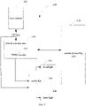
- the method includes actions in following blocks.
- At block 001 in response to a first processing unit 110 receiving an image collection instruction sent by a second processing unit 120, at least one of a floodlight 104 and a laser light 106 is turned on, and a laser camera 102 is operated to collect a target image.
- the target image is processed by the first processing unit 110, and the processed target image is sent to the second processing unit 120.
- the method for processing data of the present disclosure may be applied to an electronic device 100.
- the electronic device 100 includes a laser camera 102, a floodlight 104, a laser light 106, a first processing unit 110 and a second processing unit 120.
- the first processing unit 100 is coupled to the second processing unit 120.
- turning on the at least one of the floodlight 104 and the laser light 106 and operating the laser camera 102 to collect the target image at block 001 include actions at block 011 and block 012.
- a control instruction is sent to a controller via an inter-integrated circuit (I2C) bus.
- the control instruction is configured to turn on the at least one of the floodlight 104 and the laser light 106.
- the application may send a data obtaining request to the second processing unit 120.
- the face data may include, but be not limited to, data which needs to perform face verification in some scenarios such as face unlocking, face payment and the like, and face depth information.
- the second processing unit 120 may send the image collection instruction to the first processing unit 110 after receiving the data obtaining request.
- the first processing unit 110 may be a microprogrammed control unit (MCU) module
- the second processing unit 120 may be a central processing unit (CPU) module.
- MCU microprogrammed control unit
- CPU central processing unit
- the electronic device 100 also includes a controller 130.
- the controller 130 is respectively coupled to the floodlight 104 and the laser light 106.
- the floodlight 104 and the laser light 106 may be controlled via a same controller 130.
- the controller 130 controls the floodlight 104 and the laser light 106, for example, controls the floodlight 104 or the laser light 106 to be turned on, controls switching between the floodlight 104 and the laser light 106, controls the floodlight 104 and the laser light 106 to emit power and the like.
- the first processing unit 110 is coupled to the controller 130 by the I2C bus.
- the I2C bus may implement data transmission among respective devices connected to the bus I2C via a data line and a clock line.
- the first processing unit 110 sends a control instruction to the controller 130 via the I2C bus in response to receiving the image collection instruction sent by the second processing unit 120.
- the controller 130 turns on the at least one of the floodlight 104 and the laser light 106 according to the control instruction after receiving the control instruction.
- a pulse is sent to the controller 130 via a pulse width modulation (PWM) module to illustrate the at least one of the floodlight 104 and the laser light 106 being turned up, and the target image is collected via the laser camera 102.
- PWM pulse width modulation
- the first processing unit 110 is coupled to the controller 130 via the PWM module 112.
- the first processing unit 110 may send the pulse to the controller 130 via the PWM module 12 to illuminate the at least one of the floodlight 104 and the laser light 106 being turned up when the at least one of the floodlight 104 and the laser light 106 needs to be illuminated.
- the PWM module 112 may send pulse signals continuously to the controller 130 based on a certain voltage amplitude and a certain time interval, to illuminate the at least one of the floodlight 104 and the laser light 106.
- the first processing unit 110 may collect the target image via the laser camera 102.
- the target image may include an infrared image, a speckle image and the like.
- the PWM module 112 may send the pulse to the controller 130 to illuminate the floodlight 104.
- the floodlight 104 may be a surface light source irradiating uniformly in all directions.
- red light may be transmitted, and the laser camera 102 may collect the red light fed back the face to obtain the infrared image.
- the PWM module 112 may send the pulse to the controller 130 to illuminate the laser light 106.
- the emitted laser may be diffracted by a lens and diffractive optical elements (DOE) to generate an image with speckle particles.
- DOE diffractive optical elements
- the image with the speckle particles After the image with the speckle particles is projected to the target image, the image with the speckle particles generate offsets of the particles as distances between respective points of the target image and the electronic device 100 are different, and the laser camera 102 collects the image after the offsets of the speckle particles, to obtain the speckle image.
- the processing is performed on the target image via the first processing unit 110, and the processed target image is sent to the second processing unit 120.
- the laser camera 102 sends the collected target image to the first processing unit 110, and the first processing unit 110 performs the processing on the target image.
- the target image may include the infrared image, the speckle image and the like.
- the first processing unit 110 determines an image type according to the image collection instruction, a target image corresponding to the image type according to the determined image type, and a corresponding processing may be performed on the target image.
- the first processing unit 110 may send a pulse to the first controller 130 via the first PWM module, to illuminate the floodlight 104, and collect the infrared image via the laser camera 102.
- the first processing unit 110 performs the processing on the infrared image to obtain an infrared parallax map.
- the first processing unit 110 may send a pulse to the second controller via the second PWM module, to illuminate the laser light 106, and collect the speckle image via the laser camera 102.
- the first processing unit 110 performs the processing on the speckle image to obtain a speckle parallax image.
- the type of the collected image is a depth image
- the first processing unit 110 may collect the speckle image, and perform the processing on the collected speckle image to obtain a depth parallax map.
- the first processing unit 110 may perform correction on the target image.
- Performing the correction refers to corrections for image content offsets of the target image caused by internal parameters and external parameters of the laser camera 102 and the red green blue (RGB) camera 108, for example, for image content offsets caused by a deflection angle of the laser camera 102, and by position layout between the laser camera 102 and the RGB camera 108.
- the first processing unit 110 may obtain a parallax map of the target image after performing the correction on the target image.
- the correction may be performed on the infrared image to obtain the infrared parallax map
- the correction may be performed on the speckle image to obtain the speckle parallax map or the depth parallax map.
- the first processing unit 110 performs the correction on the target image may avoid a condition that an image finally presented on the display of the electronic device 100 appears ghosting.
- the first processing unit 110 performs the processing on the target image, and sends the processed target image to the second processing unit 120.
- the second processing unit 120 may obtain a required image based on the processed target image, such as the infrared image, the speckle image, the depth image and the like.
- the second processing unit 120 may perform further processing on the required image according to requirement of the application.
- the second processing unit 120 may perform the face detection on the required image obtained etc..
- the face detection may include face recognition, face matching and living body detection.
- the face recognition refers to recognize whether there is a face in the target image.
- the face matching refers to match the face in the target image with a preset face.
- the living body detection refers to detect whether the face in the target image is biologically active.
- the second processing unit 120 may upload the generated target depth image to the application, and the application may perform image optimization process, three-dimensional modeling and the like according to the received target depth image.
- the first processing unit 110 in response to receiving the image collection instruction sent by the second processing unit 120, sends the control instruction to the controller 130 via the I2C to turn on the at least one of the floodlight 104 and the laser light 106, and sends the pulse to the controller 130 via the PWM module 112 to illuminate the at least one of the floodlight 104 and the laser light 106 being turned on.
- the processing is performed on the target image.
- One controller 130 may realize the control for both the floodlight 104 and the laser light 106, which may reduce complexity for controlling the floodlight 104, the laser light 106 and the like, and save costs.
- FIG. 3 is an application scenario of a method for processing data of the embodiment illustrated in FIG. 2 .
- the electronic device 100 includes a laser camera 102, a floodlight 104, a laser light 106, a first processing unit 110, a second processing unit 120 and a controller 130.
- the first processing unit 110 may be a MCU module or the like.
- the second processing unit 120 may be a CPU module or the like.
- the first processing unit 110 is coupled to the laser camera 102 and the second processing unit 120.
- the first processing unit 110 is coupled to the controller 130 via an I2C bus.
- the first processing unit 110 includes a PWM module 112, and is coupled to the controller 130 via the PWM module 112.
- the controller 130 is respectively coupled to the floodlight 104 and the laser light 106.
- the first processing unit 110 sends a control instruction to the controller 130 via the I2C bus in response to receiving an image collection instruction sent by the second processing unit 120.
- the control instruction is used to control at least one of the floodlight 104 and the laser light 106 to be turned on.
- the first processing unit 110 sends a pulse to the controller 130 via the PWM module 112, to illuminate the at least one of the floodlight 104 and the laser light 106 being turned on, and collect a target image via the laser camera 102.
- the first processing unit 110 performs processing on the target image, and sends the processed target image to the second processing unit 120.
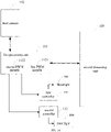
- FIG. 4 is an application scenario of a method for processing data of the embodiment illustrated in FIG. 2 .
- the electronic device 100 may include a camera module 101, a second processing unit 120, and a first processing unit 110.
- the second processing unit 120 may be a CPU module.
- the first processing unit 110 may be an MCU module or the like.
- the first processing unit 110 is coupled between the second processing unit 120 and the camera module 101.
- the first processing unit 110 may control a laser camera 102, a floodlight 104 and a laser light 106 in the camera module 101.
- the second processing unit 120 may control an RGB camera 108 in the camera module 101.
- the camera module 101 includes the laser camera 102, the floodlight 104, the RGB camera 108 and the laser light 106.
- the laser camera 102 may be an infrared camera, and may be configured to obtain an infrared image.
- the floodlight 104 may be a surface light source that can emit infrared light.
- the laser light 106 may be a point light source with a pattern that can emit laser light.
- the laser camera 102 may obtain the infrared image according to reflected light when the floodlight 104 emits the infrared light.
- the laser camera 102 may obtain a speckle image according to reflected light when the laser light 106 emits the laser light.
- the speckle image is an image with a distorted pattern after a laser forming a pattern and emitted by the laser light 106 is reflected.
- the second processing unit 120 may include a CPU kernel operating under a trusted execution environment (TEE) and a CPU kernel operating under a rich execution environment (REE). Both the TEE and the REE are operation modes of an advanced RISC machines (ARM) module.
- the REE has a higher security level.
- the second processing unit 120 only has one CPU kernel which may operate under the TEE at the same time. In general, an operation behavior with a high security level in the electronic device 100 needs to be executed in the CPU kernel under the TEE. An operation behavior with a low security level may be executed in the CPU kernel under the REE.
- the first processing unit 110 includes a pulse width modulation (PWM) module 112, a serial peripheral interface/inter-integrated circuit (SPI/I2C) interface 114, a random access memory (RAM) module 116 and a depth engine 118.
- PWM pulse width modulation
- SPI/I2C serial peripheral interface/inter-integrated circuit
- RAM random access memory
- the first processing unit 110 is coupled to the controller 130 (as illustrated in FIG. 3 ) controlling the floodlight 104 and the laser light 106 via the PWM module 112.
- the controller 130 is respectively coupled to the floodlight 104 and the laser light 106, to control the floodlight 104 and the laser light 106.
- the first processing unit 110 is also coupled to the controller 130 via the I2C bus, to control the floodlight 104 or the laser light 106 to be turned on via the I2Cbus.
- the PWM module 112 may emit pulses to the camera module 101, to illuminate the floodlight 104 or the laser light 106 being turned on.
- the first processing unit 110 may collect an infrared image or a speckle image via the laser camera 102.
- the SPI/I2C interface 114 may be configured to receive the image collection instruction sent by the second processing unit 120.
- the depth engine 118 may process the speckle image to obtain a depth parallax map.
- the image collection instruction may be sent to the first processing unit 110 through the CPU kernel operating under the TEE.
- the first processing unit 110 sends a control instruction to the controller 130 via the I2C bus, to control the floodlight 104 in the camera module 101 to be turned on, emits pulses to the controller 130 via the PWM module 112 to illuminate the floodlight 104, and controls the laser camera 102 to collect an infrared image via the I2C bus.
- the first processing unit 110 may also send a control instruction to the controller 130 via the I2C bus to control the laser light 106 in the camera module 101 to be turned on, emit pulses to the controller 130 via the PWM module 112 to illuminate the laser light 106, and controls the laser camera 102 to collect a speckle image via the I2C.
- the camera module 101 sends the collected infrared image and the collected speckle image to the first processing unit 110.
- the first processing unit 110 may perform processing on the received infrared image to obtain an infrared parallax map, and may also perform processing on the received speckle image to obtain a speckle parallax map or a depth parallax map.
- the first processing unit 110 performs the processing on the infrared image and the speckle image refers to perform correction on the infrared image or the speckle image, to remove effects caused by internal parameters and external parameters in the camera module 101 on the received images.
- the first processing unit 110 may be set to different modes, and different images are outputted in different modes.
- the first processing unit 110 processes the speckle image to obtain the speckle parallax map, according to which, a target speckle image may be obtained.
- a depth image mode the first processing unit 110 processes the speckle image to obtain the depth parallax map, according to which, a depth image may be obtained.
- the depth image refers to an image with depth information.
- the first processing unit 110 may send the infrared parallax map and the speckle parallax map to the second processing unit 120.
- the first processing unit 110 may also send the infrared parallax map and the depth parallax map to the second processing unit 120.
- the second processing unit 120 may obtain the target infrared image according to the infrared parallax map and obtain the depth image according to the depth parallax map. Further, the second processing unit 120 may perform face recognition, face matching and living body detection, and obtain depth information of the detected face according to the target infrared image and the depth image.
- the first processing unit 110 communicates with the second processing unit 120 through a fixed security interface, to ensure security for transmitting data. As illustrated in FIG. 4 , the second processing unit 120 sends data to the first processing unit 110 through a SECURE SPI/I2C 130, and the first processing unit 110 sends data to the second processing unit 120 through a SECURE mobile industry processor interface (MIPI) 140.
- MIPI SECURE mobile industry processor interface
- the first processing unit 110 may also obtain the target infrared image according to the infrared parallax map, obtain the depth image according to the depth parallax map, and send the target infrared image and the depth image to the second processing unit 120.
- collecting the target image via the laser camera 102 includes: controlling the laser camera 102 to collect the target image via the I2C bus.
- the first processing unit 110 is coupled to the laser camera via the I2C bus, and controls the laser camera 102 to collect the target image via the coupled I2C bus.
- the first processing unit 110, the laser camera 102 and the controller 130 are coupled to a same I2C bus.
- the first processing unit 110 does control the floodlight 104 or the laser light 106 to be turned on via the I2C bus, emit pulses to the controller 130 via the PWM module 112 to illuminate the floodlight 104 or the laser light 106 being turned on, and then control the laser camera 102 to collect the target image such as the infrared image or the speckle image via the coupled I2C bus.
- the first processing unit 110 may perform addressing on the controller 130 via the coupled I2C bus, send a control instruction to the controller 130 to control the floodlight 104 or the laser light 106 to be turned on, and then perform the addressing on the laser camera 102 via the coupled I2C bus to operate the laser camera 102 to collect the target image., such that the same coupled I2C bus is multiplexed at different times, thus saving resources.
- FIG. 5 is a schematic diagram illustrating a first processing unit 110, a laser camera 102 and a controller 130 being coupled to a same I2C bus according to an embodiment.
- an electronic device 100 includes the laser camera 102, a floodlight 104, a laser light 106, the first processing unit 110, a second processing unit 120 and the controller 130.
- the first processing unit 110 is coupled to the second processing unit 120.
- the first processing unit 110 includes PWM module 112, and is be- coupled to the controller 130 via the PWM module 112.
- the controller 130 is coupled to the floodlight 104 and the laser light 106 respectively.
- the laser camera 102, the first processing unit 110 and the controller 130 are coupled to the same I2C bus.
- the first processing unit 110 sends a control instruction to the controller 130 via the 12C bus, to the floodlight 104 or the laser light 106 to be turned on, sends a pulse to the controller 130 via the PWM module to illuminate the floodlight 104 or the laser light 106 being turned on, and then control the laser camera 102 to collect a target image such as an infrared image or a speckle image via the coupled I2C bus.
- the floodlight 104, the laser light 106 and the laser camera 102 are controlled via the I2C bus, and the I2C bus is multiplexed, which may reduce the complexity for controlling a circuit, and save costs.
- sending the controlling instruction to the controller 130 via the I2C bus includes following acts.
- a type of a collected image is determined based on the image collection instruction.
- the first processing unit 110 sends a first control instruction to the controller 130 via the I2C bus.
- the first control instruction is configured to instruct the controller 130 to turn on the floodlight 104.
- the first processing unit 110 receives the image collection instruction sent by the second processing unit 120, and the type of the collected image may be determined according to the image collection instruction.
- the image type may be one or more kinds of an infrared image, a speckle image, a depth image, and the like.
- the image type may be determined according to face data required by an application.
- the second processing unit 120 receives a data obtaining request, the image type may be determined according to the data obtaining request, and an image collection instruction included in the image type is sent to the first processing unit 110.
- the second processing unit 120 may determine that the image type is the infrared image or the speckle image, and when the application requires to face depth information, it is further determined that the image type is the depth image, which is not limited thereto.
- the first type may be the infrared image
- the first processing unit 110 may send the first control instruction to the controller 130 via the coupled I2C bus, and the controller 130 may turn on the floodlight 104 according to the first control instruction.
- the first processing unit 110 may emit a pulse to the controller 130 via the PWM module 112, to illuminate the floodlight 104.
- the first processing unit 110 may perform addressing on the controller 130 via the I2C bus, and send the first control instruction to the controller 130.
- the first processing unit 110 sends a second control instruction to the controller 130 via the I2C bus.
- the second control instruction is configured to instruct the controller 130 to turn on the laser light 106.
- the first processing unit 110 may send the second control instruction to the controller 130 via the coupled I2C bus.
- the controller 130 may turn on the laser light 106 according to the second control instruction.
- the first processing unit 110 may send a pulse to the controller 130 via the PWM module 112, to illuminate the laser light 106.
- the first processing unit 110 determines the type of the collected image according to the image collection instruction.
- the type of the collected image may include at least two kinds of types.
- the types of the collected image include the first type and the second type.
- the camera module 101 needs to collect the infrared image and the speckle image simultaneously.
- the first processing unit 110 may control the camera module 101 to collect the infrared image firstly, or to collect the speckle image firstly, which does not limit a collection sequence.
- the first processing unit 110 may send the first control instruction to the controller 130 via the I2C bus, to turn on the floodlight 104, and send the pulse to the controller 130 via the PWM module 112, to illuminate the floodlight 104, and then control the laser camera 102 to collect the infrared image via the I2C bus.
- the first processing unit 110 sends the second control instruction to the controller 139 via the I2C bus to turn on the laser light 106, emits a pulse to the controller 130 via the PWM module to illuminate the laser light 106, and controls the laser camera 102 to collect the speckle image via the I2C bus.
- the first processing unit 110 may also send the second instruction to the controller 130 via the I2C to turn on the laser light 106, emits a pulse to the controller 130 via the PWM module 112 to illuminate the laser light 106, and control the laser light 102 to collect the speckle image via the I2C bus.
- the first processing unit 110 sends the first control instruction to turn on the floodlight 104 via the I2C bus, emits a pulse to the controller 130 via the PWM module 112 to illuminate the floodlight 104, and controls the laser camera 102 to collect the infrared image via the I2C bus.
- the first processing unit 110 may send the first control instruction and the second control instruction to the controller 130 at different time points.
- a time interval between a time point at which the first processing unit 110 sends the first control instruction and a time point at which the first processing unit 110 sends the second processing instruction is smaller than a time threshold.
- the laser camera 102 may collect the speckle image at the time interval smaller than the time threshold after collecting the infrared image, such that image content of the collected infrared image is consistent with image content of the collected speckle image, and subsequent processing such as face detection is performed conveniently.
- the time threshold may be set based on an actual requirement, such as 20 milliseconds, 30 milliseconds or the like.
- switching and controlling between the floodlight 104 and the laser light 106 may be achieved via the controller 130, the complexity for controlling the circuit may be reduced, the costs may be reduced.
- performing the processing on the target image via the first processing unit 110 and sending the processed target image to the second processing unit 120 at block 002 include following acts.
- a reference speckle image stored is obtained, and the reference speckle image has reference depth information thereon.
- the first processing unit 110 may control a laser light 106 to be turned on via the I2C bus, and control the laser camera 102 to collect a speckle image via the I2C bus.
- the first processing unit 110 may store the reference speckle image in advance.
- the reference speckle image may have the reference depth information. Depth information of respective pixels included in the speckle image may be obtained according to the collected speckle image and the reference speckle image.
- the reference speckle image is matched with the speckle image, to obtain a matched result.
- the first processing unit 110 may take respective pixels included in the collected speckle image as the center successively, and select one pixel block with a preset size, such as a pixel size of 31 pixels * 31 pixels, and search for a block in the reference speckle image which matches the selected pixel block.
- the first processing unit 110 may find two points on a same laser light path respectively in the speckle image and the reference speckle image from the selected pixel block in the collected speckle image and the matched block in the reference speckle image. Speckle information of the two points on the same laser light path is consistent.
- the two points on the same laser light path may be identified as corresponding pixels.
- depth information of the points on each laser light path is known.
- the first processing unit 110 may calculate an offset between the two corresponding pixels on the same laser light path in the target speckle image and the reference speckle image, and obtain the depth information of respective pixels included in the collected speckle image according to the offset.
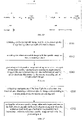
- the first processing unit 110 calculates the offset between the collected speckle image and the reference speckle image, and obtains the depth information of respective pixels included in the speckle image according to the offset by the following formula (1).
- Z D L ⁇ f ⁇ Z 0 L ⁇ ⁇ + Z 0 ⁇ P
- Z D represents depth information of a pixel, i.e., a depth value of the pixel.
- L represents a distance between the laser camera 102 and the laser (i.e., the laser light 106).
- f represents a focal length of a lens in the laser camera 102.
- Z 0 represents a depth value between a reference plane and the laser camera 102 of the electronic device 100 when the reference speckle image is collected.
- P represents the offset between the corresponding pixels in the collected speckle image and the reference speckle image.
- P may be obtained by multiplying the number of offset pixels between the target speckle image and the reference speckle image by an actual distance of one pixel.
- P is a negative value.
- P is a positive value.
- a depth parallax map is generated according to the reference depth information and the matched result, the depth parallax map is sent to the second processing unit 120, and processing is performed on the depth parallax map via the second processing unit 120 to obtain a depth image.
- the first processing unit 110 may perform correction on the collected speckle image after obtaining the depth information of respective pixels included in the collected speckle image, to correct image content offset of the collected speckle image caused by internal parameters and external parameters of the laser camera 102 and the RGB camera 108.
- the first processing unit 110 may generate the depth parallax map according to the corrected speckle image and the depth values of respective pixels in the speckle image, and send the depth parallax map to the second processing unit 120.
- the second processing unit 120 may obtain the depth image according to the depth parallax map.
- the depth image may include the depth information of respective pixels.
- the second processing unit 120 may upload the depth image to the application.
- the application may perform image optimization, three-dimensional modeling and the like according to depth information of the face in the depth image.
- the second processing unit 120 may also perform living body detection according to the depth information of the face in the depth image, which may avoid that the collected face is a face in a plane picture.
- the second processing unit 120 in the electronic device 100 may include two operation modes.
- the first operation mode may be a TEE.
- the TEE is a trusted execution environment, of which a security level is high.
- the second operation mode may be performed in the REE.
- the REE is a rich execution environment, of which a security level is low.
- the second processing unit 120 may send an image collection instruction to the first collection unit 110 through the first operation mode in response to receiving the data obtaining request sent by the application.
- the single kernel may be directly switched from the second operation mode to the first operation mode.
- the second processing unit 120 has multiple kernels, one kernel may be switched from the second operation mode to the first operation mode, other kernels still operate in the second operation mode, and the image collection instruction is sent to the first processing unit 110 through the kernel operating in the first operation mode.
- the first processing unit 110 After processing the collected target image, the first processing unit 110 sends the processed target image to the kernel operating in the first operation mode, which may ensure that the first processing unit 110 is always operating in the trusted execution environment, improving the security.
- the second processing unit 120 may be in the kernel operating in the first operation mode, obtain a required image according to the processed target image, and perform processing on the required image according to the requirement of the application. For example, the second processing unit 120 may perform face detection on the required image in the kernel operating in the first operation mode.
- the image collection instruction is sent to the first processing unit 110 through a kernel with a high security level where the second processing unit 120 operates, it may be ensured that the first processing unit 110 is in an environment with a high security level, which may improve data security.
- a serial mode may be employed to perform face recognition, face matching, living body detection and the like sequentially on the target image.
- the second processing unit 120 may perform the face recognition on the required image firstly. When a face is recognized, the second processing unit 120 matches the face included in the required image with a pre-stored face, to determine whether the two faces are identical. When the two faces are identical, the second processing unit 120 performs the living body detection on the face according to the required image, to prevent that the collected face is a plane face. When the face is not recognized, the face matching and the living body detection are not performed, which may reduce the process burden of the second processing unit 120.
- the depth information of the collected image may be obtained accurately through the first processing unit 110, the efficiency for processing data is improved and the accuracy for processing the image is improved.
- turning on the at least one of the floodlight 104 and the laser light 106 via an I2C bus and operating the laser camera 102 to collect the target image at block 011 include acts at block 021 and block 022.
- the at least one of the floodlight 104 and the laser light 106 is turned on via the I2C bus.
- the application may send a data obtaining request to the second processing unit 120.
- the face data may include, but be not limited to, data for face verification in a scenario such as face unlocking, face payment and the like, and face depth information.
- the second processing unit 120 may send the image collection instruction to the first processing unit 110 after receiving the data obtaining request.
- the first processing unit 110 may be an MCU module, and the second processing unit may be a CPU module.
- the first processing unit 110, and a laser camera 102, a floodlight 104 and a laser light 106 in a camera module 101 may be coupled to a same I2C bus.
- the I2C may implement data communication among respective elements coupled to the I2C bus through a data line and a clock line.
- the first processing unit 110 may simultaneously send control instructions to the floodlight 104 and/or the laser light 106 coupled to the I2C bus via the I2C bus, to control the at least one of the floodlight 104 and the laser light 106 to be turned on.
- the first processing unit 110 may determine a light needing to be controlled currently is the floodlight 104 or the laser light 106 according to the image collection instruction after receiving the image collection instruction.
- the first processing unit 110 may perform addressing on the floodlight 104 coupled to the I2C bus via the I2C bus, and send a control instruction to the floodlight 104, to control the floodlight 104 to be turned on.
- the first processing unit 110 may perform addressing on the laser light 106 coupled to the I2C bus via the I2C bus, and send a control instruction to the laser light 106 to control the laser light 106 to be turned on.
- the first processing unit 110 controls the laser camera 102 to collect the target image via the I2C bus.
- the first processing unit 110 controls the at least one of the floodlight 104 and the laser light 106 to be turned on via the I2C bus, and controls the laser camera 102 to collect the target image via the I2C bus.
- the target image may include an infrared image, a speckle image and the like.
- the first processing unit 110 may control the floodlight 104 in the camera module 101 to be turned on via the I2C, and control the laser camera 102 to collect the infrared image via the I2C bus.
- the floodlight 104 may be a surface light source irradiating uniformly in all directions. Light rays emitted by the floodlight 104 may be infrared light.
- the laser camera 102 may collect the red light fed back the face to obtain the infrared image.
- the laser light 106 in the camera module 102 is controlled to be turned on via the I2C bus, and the laser camera 102 is controlled to collect the speckle image and the like via the I2C bus.
- the emitted laser may be diffracted by a lens and diffractive optical elements (DOE) to generate an image with speckle particles.
- DOE diffractive optical elements
- the first processing unit 110 performs addressing on the floodlight 104 or the laser light 106 coupled to the I2C bus via the I2C bus, and sends the control instruction to the floodlight 104 or the laser light 106.
- the first processing unit 110 may perform addressing on the laser camera 102 coupled to the I2C bus via the I2C bus, and send the control instruction to the laser camera 102 to operate the laser camera 102 to collect the infrared image or the speckle image.
- the processing is performed on the target image via the first processing unit 110, and the target image processed is sent to the second processing unit 120.
- the laser camera 102 may send the collected target image to the first processing unit 110.
- the first processing unit 110 may perform processing on the target image.
- the first processing unit 110 may be set in different modes.
- the first processing unit 110 may collect different first images in different modes, and perform different processes on the target image.
- the first processing unit 110 may control the floodlight to be turned on, operate the laser camera 102 to collect an infrared image via the I2C bus, and process the infrared image to obtain an infrared parallax map.
- the first processing unit 110 may control the laser light 106 to be turned on via the I2C bus, operate the laser camera 102 to collect a speckle image via the I2C bus, and process the speckle image to obtain a speckle parallax map.
- the first processing unit 110 may control the laser light 106 to be turned on via the I2C bus, operate the laser camera 102 to collect the speckle image via the I2C bus, and process the speckle image to obtain a depth parallax map.
- the first processing unit 110 may perform correction on the target image.
- Performing the correction refers to correct image content offset of the target image caused by internal parameters and external parameters of the laser camera 102 and the RGB camera 108, such as image content offset caused by a deflection angle of the laser camera 102, and position layout between the laser camera 102 and the RGB camera 108.
- a parallax map of the target image may be obtained after performing the correction on the target image.
- the first processing unit 110 performs the correction on the infrared image to obtain the infrared parallax map, and perform the correction on the speckle image to obtain the speckle parallax map or the depth parallax map.
- Performing the correction on the target image by the first processing unit 110 may avoid a condition that an image finally presented on the display of the electronic device 100 appears ghosting.
- the first processing unit 110 may process the target image, and then send the processed target image to the second processing unit 120.
- the second processing unit 120 may obtain a required image according to the processed target image, such as an infrared image, a speckle image, a depth image, and the like.
- the second processing unit 120 may process the required image according to requirement of the application.
- the second processing unit 120 may perform face detection according to the required image and the like.
- the face detection may include face recognition, face matching and living body detection.
- the face recognition refers to recognize whether there is a face in the target image.
- the face matching refers to match the face in the target image with a preset face.
- the living body detection refers to detect whether the face in the target image is biologically active.
- the second processing unit 120 may upload the generated target depth image to the application.
- the application may perform image optimization process, three-dimensional modeling and the like according to the received depth image.
- a laser camera 102, a floodlight 104, a laser light 106 and the first processing unit 110 are coupled to a same I2C bus.
- the first processing unit 110 controls at least one of the floodlight 104 and the laser light 106 to be turned on via the I2C bus, operates the laser camera 102 to collect a target image via the I2C bus, and controls the floodlight 104, the laser light 106 and the laser camera 102 via the same I2C bus, to perform multiplexing on the I2C bus, which may reduce the complexity for controlling the circuit and reduce the costs.
- FIG. 5 is an application scenario of a method for processing data of the embodiment illustrated in FIG. 8 .
- the electronic device 100 includes a laser camera 102, a laser light 106, a floodlight 104, a first processing unit 110, a second processing unit 120 and a controller 130.
- the first processing unit 110 may be a MCU module or the like.
- the second processing unit 120 may be a CPU module or the like.
- the first processing unit 110 is coupled to the laser camera 102, the laser light 106, the floodlight 104 and the second processing unit 120.
- the controller 130 may be respectively coupled to the floodlight 104 and the laser light 106.
- the controller 130 may control the laser light 106 and the floodlight 104.
- the laser camera 102, the controller 130 and the first processing unit 110 are coupled to an I2C bus.
- the first processing unit 110 controls at least one of the floodlight 104 and the laser light 106 to be turned on via the I2C bus in response to receiving an image collection instruction sent by the second processing unit 120.
- the first processing unit 110 sends the control instruction to the controller 130 coupled the I2C bus.
- the controller 130 controls the at least one of the floodlight 104 and the laser light 106 to be turned on according to a control instruction after receiving the control instruction.
- the first processing unit 110 may illuminate the floodlight 104 and the laser light 106 via a PWM module 112.
- the first processing unit 110 operates the laser camera 102 to collect the target image via the I2C bus.
- the first processing unit 110 performs processing on the collected target image, and sends the processed target image to the second processing unit 120.
- FIG. 4 is another application scenario of the method for processing data of the embodiment illustrated in FIG. 8 .
- the electronic device 100 includes a camera module 101, a second processing unit 120, and a first processing unit 110.
- the second processing unit 120 may be CPU module.
- the first processing unit 110 may be a MCU module or the like.
- the first processing unit 110 is coupled between the second processing unit 120 and the camera module 101.
- the first processing unit 110 may control a laser camera 102, a floodlight 104 and a laser light 106 in the camera module 101.
- the second processing unit 120 may control a RGB camera 108 in the camera module 101.
- the camera module 101 includes the laser camera 102, the floodlight 104, the RGB camera 108 and the laser light 106.
- the laser camera 102 may be an infrared camera, and may be configured to obtain an infrared image.
- the floodlight 104 may be a surface light source that can emit infrared light.
- the laser light 106 may be a point light source with a pattern that can emit laser light.
- the laser camera 102 may obtain the infrared image according to reflected light when the floodlight 104 emits the infrared light.
- the laser camera 102 may obtain a speckle image according to reflected light when the laser light 106 emits the laser light.
- the speckle image is an image with a distorted pattern after a laser having a pattern and emitted by the laser light 106 is reflected.
- the laser camera 102, the floodlight 104, the laser light 106 and the first processing unit 110 are coupled to a same I2C bus.
- the second processing unit 120 may include a CPU kernel operating under a trusted execution environment (TEE) and a CPU kernel operating under a rich execution environment (REE). Both the TEE and the REE are operation modes of an advanced RISC machines (ARM) module.
- the REE has a higher security level.
- the second processing unit 120 only has one CPU kernel which may operate under the TEE at the same time. In general, an operation behavior with a high security level in the electronic device 100 needs to be executed in the CPU kernel under the TEE. An operation behavior with a low security level may be executed in the CPU kernel under the REE.
- the first processing unit 110 includes a pulse width modulation (PWM) module 112, a serial peripheral interface/inter-integrated circuit (SPI/I2C) interface 114, a random access memory (RAM) module 116 and a depth engine 118.
- PWM pulse width modulation
- SPI/I2C serial peripheral interface/inter-integrated circuit
- RAM random access memory
- the first processing unit 110 controls the floodlight 104 or the laser light 106 via the coupled I2C bus.
- the above PWM module 112 may emit a pulse to the camera module 101, to illuminate the floodlight 104 or the laser light 106 being turned on.
- the first processing unit 110 may operate the laser camera 102 to collect an infrared image or a speckle image via the I2C bus.
- the SPI/I2C interface 114 may be configured to receive the image collection instruction sent by the second processing unit 120.
- the depth engine 118 may process the speckle image to obtain a depth parallax map.
- the image collection instruction may be sent to the first processing unit 110 through the CPU kernel operating under the TEE.
- the first processing unit 110 may control the floodlight 104 in the camera module 101 to be turned on via the I2C bus, emits a pulse via the PWM module 112 to illuminate the floodlight 104, and operates the laser camera 102 to collect an infrared image via the I2C bus, and the first processing unit 110 may also control the laser light 106 in the camera module 101 to be turned on via the I2C bus and operates the laser camera 102 to collect a speckle image via the I2C.
- the camera module 101 sends the collected infrared image and the collected speckle image to the first processing unit 110.
- the first processing unit 110 may perform processing on the received infrared image to obtain an infrared parallax map, and may also perform processing on the received speckle image to obtain a speckle parallax map or a depth parallax map.
- the first processing unit 110 performs the processing on the infrared image and the speckle image refers to perform correction on the infrared image or the speckle image, to remove effects caused by internal parameters and external parameters in the camera module 101 on the received images.
- the first processing unit 110 may be set to different modes, and different images are outputted in different modes.
- the first processing unit 110 When the first processing unit 110 is set to a speckle image mode, the first processing unit 110 processes the speckle image to obtain the speckle parallax map, according to which, a target speckle image may be obtained.
- the first processing unit 110 When the first processing unit 110 is set to a depth image mode, the first processing unit 110 processes the speckle image to obtain the depth parallax map, according to which, a depth image may be obtained.
- the depth image refers to an image with depth information.
- the first processing unit 110 may send the infrared parallax map and the speckle parallax map to the second processing unit 120.
- the first processing unit 110 may also send the infrared parallax map and the depth parallax map to the second processing unit 120.
- the second processing unit 120 may obtain the target infrared image according to the infrared parallax map and obtain the depth image according to the depth parallax map. Further, the second processing unit 120 may perform face recognition, face matching and living body detection, and obtain depth information of the detected face according to the target infrared image and the depth image.
- the first processing unit 110 communicates with the second processing unit 120 through a fixed security interface, to ensure security for transmitting data. As illustrated in FIG. 4 , the second processing unit 120 sends data to the first processing unit 110 through a SECURE SPI/I2C 130, and the first processing unit 110 sends data to the second processing unit 120 through a SECURE mobile industry processor interface (MIPI) 140.
- MIPI SECURE mobile industry processor interface
- the first processing unit 110 may also obtain the target infrared image according to the infrared parallax map, obtain the depth image according to the depth parallax map, and send the target infrared image and the depth image to the second processing unit 120.
- controlling the at least one of the floodlight and the laser light to be turned on via the I2C bus includes following acts.
- a collected image type is determined according to the image collection instruction.
- the first processing unit 110 receives an image collection instruction sent by the second processing unit 120, and the type of the collected image may be determined according to the image collection instruction.
- the type of the collected image may be one or more kinds of an infrared image, a speckle image, a depth image, and the like.
- the type may be determined according to face data required by an application.
- the second processing unit 120 receives a data obtaining request, the type may be determined according to the data obtaining request, and an image collection instruction included in the type is sent to the first processing unit 110.
- the type of the collected image may be determined to be the infrared image or the speckle image
- the type of the collected image may be determined to be the depth image, which is not limited thereto.
- the first processing unit 110 sends a first control instruction to the controller 130 via the I2C bus when the image type is an infrared image, and the first control instruction is configured to instruct the controller 130 to turn on the floodlight 104.
- the electronic device 100 may also be provided with a controller 130.
- the floodlight 104 and the laser light 106 may share a same controller 130.
- the controller 130 is coupled to the floodlight 104 and the laser light 106 respectively.
- the controller 130 is configured to control the floodlight 104 and the laser light 106, which may include to control the floodlight 104 or the laser light 106 to be turned on, to control switching between the floodlight 104 and the laser light 106, and to control the floodlight 104 and the laser light 106 to emit power.
- the controller 130, the laser camera 102 and the first processing unit 110 is coupled to a same I2C bus.
- the first processing unit 110 may send a first control instruction to the controller 130 via the coupled I2C bus, and the controller 130 may control the floodlight 104 to be turned on according to the first control instruction.
- the first processing unit 110 may emit a pulse to the controller 130 through the PWM module 112, to illuminate the floodlight.
- the first processing unit 110 may perform addressing on the controller 130 via the I2C, and send the first control instruction to the controller 130.
- the first processing unit 110 sends a second control instruction to the controller 130 via the 12C bus when the type is a speckle image or a depth image, and the second control instruction is configured to instruct the controller 130 to turn on the laser light.
- the first processing unit 110 sends the second control instruction to the controller 130 via the coupled I2C bus, and the controller 130 may control the laser light 106 to be turned on according to the second control instruction.
- the first processing unit 110 may send a pulse to the controller 130 via a PWM module 12, to illuminate the laser light 106.
- the types may be multiple, which may include the infrared image and the speckle image simultaneously, include the infrared image and the depth image simultaneously, or include the infrared image, the speckle image and the depth image simultaneously.
- the first processing unit 110 may respectively control the floodlight 104 to be turned on to collect the infrared image, and turn on the laser light 106 to collect the speckle image.
- the first processing unit 110 may operate the laser camera 102 to collect the infrared image firstly, or may also operate the laser light 102 to collect the speckle image firstly.
- the collection sequence is not limited herein.
- the first processing unit 110 may send the first control instruction to the controller 130 via the I2C bus to turn on the floodlight 104, operate the laser camera 102 to collect the infrared image via the I2C bus, send the second control instruction to the controller 130 via the I2C bus to turn on the laser light 106, and operate the laser camera 102 to collect the speckle image via the I2C bus.
- the first processing unit 110 may send the second control instruction to the controller 130 via the I2C bus to turn on the laser light 106, operate the laser camera 102 to collect the infrared image via the I2C bus, send the first control instruction to the controller 130 via the I2C bus to turn on the floodlight 104, and operate the laser camera 102 to collect the speckle image via the I2C bus.
- time division multiplexing may be performed on the same I2C bus, which may reduce the complexity for controlling the circuit, and reduce the costs.
- the first processing unit 110 may implement switching and control between the floodlight 104 and the laser light 106 via a controller 130, which may further reduce the complexity for controlling the circuit, and reduce the costs.
- performing processing on the target image via the first processing unit 110 and sending the processed target image to the second processing unit 120 at block 002 may include actions in following blocks.
- a reference speckle image stored is obtained, and the reference speckle image has reference depth information thereon.
- a line perpendicular to an imaging plane and passing through a center of a mirror is taken as Z axis.
- Z value is the depth information of the object in the imaging plane of the camera.
- the first processing unit 110 may control to turn on a laser light 106 via the I2C bus, and operate the laser camera 102 to collect a speckle image via the I2C bus.
- the first processing unit 110 may store the reference speckle image in advance.
- the reference speckle image may have the reference depth information. Depth information of respective pixels included in the speckle image may be obtained according to the collected speckle image and the reference speckle image.
- the reference speckle image is matched with the speckle image, to obtain a matched result.
- the first processing unit 110 may take respective pixels included in the collected speckle image as the center successively, and select one pixel block with a preset size, such as a pixel size of 31 pixels * 31 pixels, and search for a block in the reference speckle image which matches the selected pixel block.
- the first processing unit 110 may find two points on a same laser light path respectively in the speckle image and the reference speckle image from the selected pixel block in the collected speckle image and the matched block in the reference speckle image. Speckle information of the two points on the same laser light path is consistent.
- the two points on the same laser light path may be identified as corresponding pixels.
- depth information of the points on each laser light path is known.
- the first processing unit 110 may calculate an offset between the two corresponding pixels on the same laser light path in the target speckle image and the reference speckle image, and obtain the depth information of respective pixels included in the collected speckle image according to the offset.
- the first processing unit 110 calculates the offset between the collected speckle image and the reference speckle image, and obtains the depth information of respective pixels included in the speckle image according to the offset by the following formula (2).
- Z D L ⁇ f ⁇ Z 0 L ⁇ ⁇ + Z 0 ⁇ P
- Z D represents depth information of a pixel, i.e., a depth value of the pixel.
- L represents a distance between the laser camera 102 and the laser (i.e., the laser light 106).
- f represents a focal length of a lens in the laser camera 102.
- Z 0 represents a depth value between a reference plane and the laser camera 102 of the electronic device 100 when the reference speckle image is collected.
- P represents the offset between the corresponding pixels in the collected speckle image and the reference speckle image.
- P may be obtained by multiplying the number of offset pixels between the target speckle image and the reference speckle image by an actual distance of one pixel.
- P is a negative value.
- P is a positive value.
- a depth parallax map is generated according to the reference depth information and the matched result, the depth parallax map is sent to the second processing unit 120, and the depth parallax map is processed by the second processing unit 120 to obtain a depth image.
- the first processing unit 110 may perform correction on the collected speckle image after obtaining the depth information of respective pixels included in the collected speckle image, to correct image content offset of the collected speckle image caused by internal parameters and external parameters of the laser camera 102 and the RGB camera 108.
- the first processing unit 110 may generate the depth parallax map according to the corrected speckle image and the depth values of respective pixels in the speckle image, and send the depth parallax map to the second processing unit 120.
- the second processing unit 120 may obtain the depth image according to the depth parallax map.
- the depth image may include the depth information of respective pixels.
- the second processing unit 120 may upload the depth image to the application.
- the application may perform image optimization, three-dimensional modeling and the like according to depth information of the face in the depth image.
- the second processing unit 120 may also perform living body detection according to the depth information of the face in the depth image, which may avoid that the collected face is a plane face.
- the depth information of the image may be collected accurately via the first processing unit 110, which improves the efficiency for processing data, and improves the accuracy for processing the image.
- the method for processing data further includes acts in following blocks.
- a temperature of a laser 106 is collected every collection time period, and a reference speckle image corresponding to the temperature is obtained via the second processing unit 120.
- An electronic device 100 may be provided with a temperature sensor beside a laser 106 and collect the temperature of the laser light 106 and the like through the temperature sensor.
- the second processing unit 120 may obtain the temperature of the laser light 106 collected by the temperature sensor every collection time period.
- the collection time period may be set according to the actual requirement, such as 3 seconds, 4 seconds or the like, which is not limited thereto.
- a camera module 101 may be deformed, affecting internal and external parameters of the laser light 106 and the laser camera 102. Effects on the camera module 101 are different under different temperatures. Therefore, reference speckle images may be different at different temperatures.
- the second processing unit 120 may obtain the reference speckle image corresponding to the temperature, and process the speckle image collected under the temperature according to the reference speckle image corresponding to the temperature, to obtain the depth image.
- the second processing unit may set lots of different temperature ranges in advance, such as 0°C ⁇ 30°C, 30°C ⁇ 60°C, 60°C ⁇ 90°C and the like, which is not limited thereto. Different temperature ranges may correspond to different reference speckle images.
- the second processing unit 120 may determine the temperature range to which the collected temperature belongs, and obtain the reference speckle image corresponding to the temperature range.
- the reference speckle image obtained at the present time is written into the first processing unit 110 via the second processing unit 120 when the reference speckle image obtained at the present time is inconsistent with the reference speckle image stored in the first processing unit 110.
- the second processing unit 120 may determine whether the reference speckle image obtained at the present time is consistent with the reference speckle image stored in the first processing unit 110 after obtaining the reference speckle image corresponding to the collected temperature.
- the reference speckle image may have an image identifier.
- the image identifier may be combined by one or more of numbers, letters, characters, etc.
- the second processing unit 120 may read the image identifier of the reference speckle image stored in the first processing unit 110, and compare the image identifier of the reference speckle image obtained at the present time with the image identifier read from the first processing unit 110.
- the second processing unit 120 may write the reference speckle image obtained at the present time into the first processing unit 110.
- the first processing unit 110 may store the newly written reference speckle image and delete the previously stored reference speckle image.
- the reference speckle image corresponding to the temperature of the laser light 106 may be obtained, which reduces the effect of the temperature on the depth map outputted finally, and enables that the obtained depth information is more accurate.
- the method for processing data of the embodiment illustrated in FIG. 8 please refer to FIG. 4 , FIG. 5 and FIG. 12 .
- the method for processing data further includes an act at block 0261, and sending the processed target image to the second processing unit includes an act at block 0262.
- the image collection instruction is sent to the first processing unit 110 through a kernel of the second processing unit operating in a first operation mode.
- the first operation mode is a trusted execution environment.
- the second processing unit 120 in the electronic device 100 may include two operation modes.
- the first operation mode may be a TEE.
- the TEE is the trusted execution environment, of which the security level is high.
- the second operation mode may be a REE.
- the REE is a rich execution environment, of which the security level is low.
- the second processing unit 120 may send the image collection instruction to the first processing unit 110 in the first operation mode in response to receiving a data obtaining request sent by the application.
- the core When the second processing unit 120 is a CPU with one core, the core may be directly switched from the second operation mode to the first operation mode.
- the second processing unit 120 has multiple kernels, one kernel may be switched from the second operation mode to the first operation mode, and other kernels still operate in the second operation mode.
- the image collection instruction is sent to the first processing unit 110 through the kernel operating in the first operation mode.
- the first processing unit 110 sends the processed target image to the kernel of the second processing unit 120 operating in the first operation mode.
- the first processing unit 110 may send the processed first image to the kernel operating in the first operation mode after processing the collected first process image, which may ensure that the first processing unit 110 always operate in the trusted execution environment and improve the security.
- the second processing unit 120 may obtain the target image according to the processed first image in the kernel operating in the first operation mode, and process the target image according to the requirement of the application in the kernel operating in the first operation mode. For example, the second processing unit 120 may perform face detection on the target image in the kernel operating in the first operation mode.
- a serial mode may be employed to perform face recognition, face matching, living body detection and the like sequentially on the target image.
- the second processing unit 120 may perform the face recognition on the target image firstly. When a face is recognized, the second processing unit 120 matches the face included in the target image with a pre-stored face, to determine whether the two faces are identical. When the two faces are identical, the second processing unit 120 performs the living body detection on the face according to the target image, to prevent that the collected face is a plane face. When the face is not recognized, the face matching and the living body detection are not performed, which may reduce the process burden of the second processing unit 120.
- the image collection instruction is sent to the first processing unit 110 via the kernel of the second processing unit 120 with a high security, which may ensure that the first processing unit 110 is in an environment with a high security and improve the security of data.
- turning on the at least one of the floodlight 104 and the laser light 106 and operating the laser camera 102 to collect the target image at block 011 include actions in block 031, block 032 and block 033.
- a type of a collected image is determined according to the image collection instruction in response to the first processing unit 110 receiving the image collection instruction sent by the second processing unit 120.
- the application may send a data obtaining request to the second processing unit 120.
- the face data may include, but be not limited to, data for face verification in a scenario such as face unlocking, face payment and the like, and face depth information.
- the second processing unit 120 may send the image collection instruction to the first processing unit 110 after receiving the data obtaining request.
- the first processing unit 110 may be an MCU module, and the second processing unit may be a CPU module.
- the first processing unit 110 may receive the image collection instruction sent by the second processing unit 120, and determine the image type of the image according to the image collection instruction.
- the image type may be one or more of the infrared image, the speckle image, the depth image and the like.
- the image type may be determined according to face data required by the application.
- the second processing unit 120 may determine the image type according to the data obtaining request after receiving the data obtaining request, and send the image collection instruction including the type of the image to the first processing unit 110.
- the second processing unit 120 may determine that the type of the image may be the infrared image or the speckle image, and when the application requires the face depth information, the second processing unit 120 may further determine that the type of the image is the depth image or the like, which is not limited herein.
- the floodlight in a camera module 101 is turned on, a pulse is sent to a first controller 131 via a first PWM module 1121 to illuminate the floodlight 104, and then a target image corresponding to the first type is collected via the laser camera 102 in the camera module 101.
- the first processing unit 110 may send a control instruction to the first controller 131.
- the instruction may be configured to turn on the floodlight 104 in the camera module 101.
- the first processing unit 110 may send a pulse signal to the first controller 131 configured to control the floodlight 104 via the first PWM module 1121, to illuminate the floodlight 104.
- the first PWM module 1121 may sent pulse signals continuously to the floodlight 104 based on a certain voltage amplitude and a certain time interval, to illuminate the floodlight 104.
- the floodlight 104 may be a surface light source irradiating uniformly in all directions. When the floodlight 104 is illuminated, red light may be emitted, and the laser camera 102 may collect the red light fed back the face to obtain the infrared image.
- the laser light 106 in the camera module 102 is turned on, a pulse is sent to a second controller 132 via a second PWM module 1122 to illuminate the laser light 106, and then a target image corresponding to the second type is collected via the laser camera 102 in the camera module 101.
- the first processing unit 110 may send a control instruction to the second controller 132.
- the control instruction may be configured to turn on the laser light 106 in the camera module 101.
- the first processing unit 110 may send a pulse signal to the second controller 132 configured to control the laser light 106 via the second PWM module 1122, to illuminate the laser light 106.
- the second PWM module 1122 may send pulse signals continuously to the laser light 106 based on a certain voltage amplitude and a certain time interval, to illuminate the laser light 106.
- the emitted laser may be diffracted by a lens and diffractive optical elements (DOE) to generate an image with speckle particles.
- DOE diffractive optical elements
- the target image is processed by the first processing unit 110, and the processed target image is sent to the second processing unit 120.
- the laser camera 102 may send the collected target image to the first processing unit 110, and the first processing unit 110 may perform processing on the target image.
- the target image may include the infrared image, the speckle image and the like.
- the first processing unit 110 may perform corresponding processing on the target image based on the determined type of the collected image and the target image corresponding to the type.
- the first processing unit 110 may send the pulse to the first controller 131 via the first PWM module 1121 to illuminate the floodlight 104, collect the infrared image via the laser camera 102, and perform processing on the infrared image to obtain an infrared parallax map.
- the first processing unit 110 may send the pulse to the second controller 132 via the second PWM module to illuminate the laser light 106, collect the speckle image via the laser camera 102, and perform processing on the speckle image to obtain a speckle parallax image.
- the first processing unit 110 may collect the speckle image, and perform processing on the collected speckle image to obtain a depth parallax map.
- the first processing unit 110 may perform correction on the target image.
- Performing the correction refers to correct image content offset of the target image caused by internal parameters and external parameters of the laser camera 102 and the red green blue (RGB) camera 108, such as image content offset caused by a deflection angle of the laser camera 102, and position layout between the laser camera 102 and the RGB camera 108.
- a parallax map of the target image may be obtained after the first processing unit 110 performs the correction on the target image.
- the correction may be performed on the infrared image to obtain the infrared parallax map
- the correction may be performed on the speckle image to obtain the speckle parallax map or the depth parallax map.
- the first processing unit 110 performs the correction on the target image may avoid a condition that an image finally presented on the display of the electronic device 100 appears ghosting.
- the first processing unit 110 performs processing on the target image, and may send the processed target image to the second processing unit 120.
- the second processing unit 120 may obtain a requirement image based on the processed target image, such as the infrared image, the speckle image, the depth image and the like.
- the second processing unit 120 may perform further processing on the image needed according to requirement of the application.
- the second processing unit 120 may perform the face detection on a required image obtained and the like.
- the face detection may include face recognition, face matching and living body detection.
- the face recognition refers to recognize whether there is a face in the target image.
- the face matching refers to match the face in the required image with a preset face.
- the living body detection refers to detect whether the face in the target image is biologically active.
- the application needs to obtain depth information of the face, the generated target depth image may be uploaded to the application.
- the application may perform image optimization process, three-dimensional modeling and the like according to the received target depth image.
- the type of the collected image is determined according to the image collection instruction.
- the floodlight 104 is illuminated via the first PWM module 1121, and the target image corresponding to the first type is collected via the laser camera 102.
- the pulse is sent to the second controller 132 via the second PWM module 1122 to illuminate the laser light 106, and the target image corresponding to the second type is collected via the laser camera 102.
- the floodlight 104 and the laser light 106 are controlled respectively via two PWM modules, which do not need to switch in real time, may reduce complexity for processing data, and reduce the process pressure of the first processing unit 110.
- FIG. 14 is an application scenario illustrating the method for processing data of the embodiment illustrated in FIG. 13 .
- the method for processing data may be applied to the electronic device 100.
- the electronic device 100 includes a laser camera 102, a floodlight 104, a laser light 106, a first processing unit 110, a second processing unit 120 and a first controller 131 and a second controller 132.
- the first processing unit 110 is coupled to the laser camera 102 and the second processing unit 120 respectively.
- the first processing unit 110 may be a MCU module or the like.
- the second processing unit 120 may be a CPU module or the like.
- the first controller 131 may be coupled to the floodlight 104.
- the second controller 132 may be coupled to the laser light 106.
- the first processing unit 110 may include a first PWM module 1121 and a second PWM module 1122.
- the first processing unit 110 may be coupled to the first controller 131 via the first PWM module 1121.
- the first processing unit 110 is coupled to the second controller 132 via the second PWM module 1122.
- the first processing unit 110 determines the image type according to an image collection instruction in response to receiving the image collection instruction sent by the second processing unit 120.
- the image type is a first type
- the floodlight 104 is turned on, a pulse is sent to the first controller 131 via the first PWM module 1121 to illuminate the floodlight 104, and a target image corresponding to the first type is collected via the laser camera 102.
- the type of the image is a second type
- the laser light 106 is turned on, a pulse is sent to the second controller 132 via the second PWM module 1122 to illuminate the laser light 106, and a target image corresponding to the second type is collected via the laser camera 102.
- the first processing unit 110 does perform processing on the target image collected by the laser camera 102, and send the processed target image to the second processing unit 120.
- FIG. 4 is an application scenario illustrating the method for processing data of the embodiment illustrated in FIG. 13 .
- the electronic device 100 may include a camera module 101, a second processing unit 120, and a first processing unit 110.
- the second processing unit 120 may be a CPU module.
- the first processing unit 110 may be an MCU module or the like.
- the first processing unit 110 is coupled between the second processing unit 120 and the camera module 101.
- the first processing unit 110 may control a laser camera 101, a floodlight 104 and a laser light 106 in the camera module 101.
- the second processing unit 120 may control an RGB camera 108 in the camera module 101.
- the camera module 101 includes a laser camera 102, a floodlight 104, the RGB camera 108 and a laser light 106.
- the laser camera 102 may be an infrared camera, and may be configured to obtain an infrared image.
- the floodlight 104 may be a surface light source that can emit infrared light.
- the laser light 106 may be a point light source with a pattern that can emit laser light.
- the laser camera 212 may obtain the infrared image according to reflected light when the floodlight 104 emits the infrared light.
- the laser camera 106 may obtain a speckle image according to reflected light when the laser light 106 emits the laser light.
- the speckle image is an image with a distorted pattern after a laser forming a pattern and emitted by the laser light 106 is reflected.
- the second processing unit 120 may include a CPU kernel operating under a trusted execution environment (TEE) and a CPU kernel operating under a rich execution environment (REE). Both the TEE and the REE are operation modes of an advanced RISC machines (ARM) module.
- the REE has a higher security level.
- the second processing unit 120 only has one CPU kernel which may operate under the TEE at the same time. In general, an operation behavior with a high security level in the electronic device 100 needs to be executed in the CPU kernel under the TEE. An operation behavior with a low security level may be executed in the CPU kernel under the REE.
- the first processing unit 110 includes a pulse width modulation (PWM) module 112, a serial peripheral interface/inter-integrated circuit (SPI/I2C) interface 114, a random access memory (RAM) module 116 and a depth engine 118.
- the PWM module 232 may include a first PWM module and a second PWM module 1122.
- the first PWM module 1121 may be coupled to a controller 131 of the floodlight 104 to control the floodlight 104 to be turned on, and emit a pulse to the floodlight 104 to illuminate the floodlight 104.
- the second PWM module 1122 may be coupled to the controller 132 of the laser light 106 to control the laser light 106 to be turned on, and emit a pulse to the laser light 106 to illuminate the laser light 106.
- the SPI/I2C interface 114 may be configured to receive the image collection instruction sent by the second processing unit 120.
- the depth engine 118 may process the speckle image to obtain a depth parallax map.
- the image collection instruction may be sent to the first processing unit 110 through the CPU kernel operating under the TEE.
- the first processing unit 110 may emit pulses to illuminate the floodlight 104 via the first PWM module 1121 in the PWM module 112 and collect the infrared image via the laser camera 102, and the first processing unit 110 may emit pulses to illuminate the laser light 106 via the second PWM module 1122 in the PWM module 112 and collect the speckle image via the laser camera 102.
- the camera module 101 may send the collected infrared image and the collected speckle image to the first processing unit 110.
- the first processing unit 110 may process the received infrared image to obtain an infrared parallax map and process the received speckle image to obtain a speckle parallax map or a depth parallax map.
- the first processing unit 110 processes the received infrared image and the received speckle image as follows.
- the first processing unit 110 performs correction on the received infrared image or the received speckle image, to remove effects caused by internal parameters and external parameters in the camera module 101 on the received images.
- the first processing unit 110 may be set to different modes, and different images are outputted in different modes. When the first processing unit 110 is set to a speckle image mode, the first processing unit 110 processes the speckle image to obtain the speckle parallax map, according to which, a target speckle image may be obtained.
- the first processing unit 110 processes the speckle image to obtain the depth parallax map, according to which, a depth image may be obtained.
- the depth image refers to an image with depth information.
- the first processing unit 110 may send the infrared parallax map and the speckle parallax map to the second processing unit 120.
- the first processing unit 110 may also send the infrared parallax map and the depth parallax map to the second processing unit 120.
- the second processing unit 120 may obtain the target infrared image according to the infrared parallax map and obtain the depth image according to the depth parallax map. Further, the second processing unit 120 may perform face recognition, face matching and living body detection, and obtain depth information of the detected face according to the target infrared image and the depth image.
- the first processing unit 110 communicates with the second processing unit 120 through a fixed security interface, to ensure security for transmitting data. As illustrated in FIG. 4 , the second processing unit 120 sends data to the first processing unit 110 through a SECURE SPI/I2C 130, and the first processing unit 110 sends data to the second processing unit 120 through a SECURE mobile industry processor interface (MIPI) 140.
- MIPI SECURE mobile industry processor interface
- the first processing unit 110 may also obtain the target infrared image according to the infrared parallax map, obtain the depth image according to the depth parallax map, and send the target infrared image and the depth image to the second processing unit 120.
- the method further includes: configuring, by the second processing unit 120, the floodlight 104 and the laser light 106 respectively via the I2C bus when it is detected that the camera module 101 is activated.
- the camera module 101 When an application of the electronic device 100 needs to collect required image data via the camera module 101, the camera module 101 may be activated, and the image is collected via the camera module 101.
- the second processing unit 120 may configure the floodlight 104 and the laser light 106 via the I2C bus respectively.
- the I2C bus may implement data transmission among respective devices connected to the bus I2C via a data line and a clock line.
- the second processing unit 120 may read a configured file firstly and perform configuration on the floodlight 104 and the laser light 106 according to parameters included in the configured file.
- the configured file may record the parameters such as emission powers, emission currents and the like of the floodlight 104 and the laser light 106, but is not limited thereto, and may be other parameters.
- the second processing unit 120 may set the parameters such as the emission powers, the emission currents and the like of the floodlight 104 and the laser light 106 according to the parameters in the configured file.
- the second processing unit 120 may be coupled to the floodlight 104 and the laser light 106 respectively via a same I2C bus.
- the floodlight 104, the laser light 106 and the second processing unit 120 may be coupled to the same I2C bus.
- the second processing unit 120 may perform addressing on the floodlight 104 via the I2C and perform the configuration on the floodlight 104, and then the second processing unit 120 may perform the addressing on the laser light 106 via the I2C bus and perform the configuration on the laser light 106.
- the second processing unit 120 may also perform the addressing on the laser light 106 via the I2C bus firstly and perform the configuration on the laser light 106, and then the second processing unit 120 may perform the addressing on the floodlight 104 via the I2C bus and perform the configuration on the floodlight 104.
- Time division multiplexing may be performed on the coupled same I2C bus, which may reduce the complexity for controlling the circuit, save sources and reduce the costs.
- the second processing unit 120 may also be coupled to the floodlight 104 and the laser light 106 via two I2C buses respectively.
- the second processing unit 120 may be coupled to the floodlight 104 via one I2C bus and to the laser light 106 via the other I2C bus.
- the second processing unit 120 may perform the addressing on the floodlight 104 via the I2C bus coupled to the floodlight to configure the floodlight 104, and the second processing unit 120 may perform addressing on the laser light 106 via the I2C bus coupled to the laser light 106 to configure the laser light 106 simultaneously.
- the floodlight 104 and the laser light 106 are coupled respectively via two I2C buses, and the configuration may be performed on the floodlight 104 and the laser light 106 in parallel, which improve the velocity for processing data.
- FIG. 15 is a schematic diagram illustrating a second processing unit 120 being coupled to a floodlight 104 and a laser light 106 according to an embodiment.
- the second processing unit 120 is coupled to the floodlight 104 and the laser light 106 respectively via an I2C bus.
- the second processing unit 120 is coupled to the floodlight 104 and the laser light 106 respectively via two I2C buses.
- the second processing unit 120 may be coupled to the floodlight 104 via one I2C bus, and to the laser light 106 via the other I2C bus.
- the second processing unit 120 may perform the configuration on the floodlight 104 and the laser light 106 via the I2C bus, which may control the image collection more accurately and improve the efficiency of data processing.
- a time point at which the first PWM module 1121 sends the pulse to the first controller 131 is different from a time point at which the second PWM module 1122 sends the pulse to the second controller 132, and a time interval between the time point at which the first PWM module 1121 sends the pulse to the first controller 131 and the time point at which the second PWM module 1122 sends the pulse to the second controller 132 is smaller than a time threshold.
- the first processing unit 110 determines the image type of the collected image according to the image collection instruction. There may be two image types. For example, the image types may include a first type and a second type. When the type of the collected image includes the infrared image and the speckle image simultaneously, or includes the speckle image and the depth image simultaneously, there is a need to collect the infrared image and the speckle image simultaneously.
- the first processing unit 110 may send the pulse to the first controller 131 via the first PWM module 121 and send the pulse to the second controller 132 via the second PWM module 1122, to illuminate the floodlight 104 and the laser light 106.
- the time point at which the first PWM module 1121 sends the pulse to the first controller 131 may be different from the time point at which the second PWM module 1122 sends the pulse to the second controller 132, thus illuminating the floodlight 104 and the laser light 106 at different time points.
- the first processing unit 110 may collect the infrared image via the laser camera 102 when the first PWM module 1121 sends the pulse to the first controller 131, and collect the speckle image via the laser camera 102 when the second PWM module 1122 sends the pulse to the second controller 132.
- the time interval between the time point at which the first PWM module 1121 sends the pulse to the first controller 131 and the time point at which the second PWM module 1122 sends the pulse to the second controller 132 is smaller than the time threshold.
- the laser camera 102 may collect the speckle image in the time interval which is smaller than the time threshold after collecting the infrared image, such that image content of the collected infrared image is consistent with image content of the collected speckle image, and subsequent processing such as face detection is performed conveniently.
- the time threshold may be set based on an actual requirement, such as 20 milliseconds, 30 milliseconds or the like.
- the first processing unit 110 may collect the infrared image and the speckle image respectively via the laser camera 102 at different time points, which may ensure that the image content of the collected infrared image is consistent with the image content of the collected speckle image, and improve the accuracy of subsequent face detection.
- performing the processing on the target image via the first processing unit 110 and sending the processed target image to the second processing unit 120 at block 002 include actions in following blocks.
- a reference speckle image stored is obtained, and the reference speckle image has reference depth information thereon.
- the first processing unit 110 may control a laser light 106 to be turned on via the I2C bus, and operate the laser camera 102 to collect a speckle image via the I2C bus.
- the first processing unit 110 may store the reference speckle image in advance.
- the reference speckle image may have the reference depth information. Depth information of respective pixels included in the speckle image may be obtained according to the collected speckle image and the reference speckle image.
- the reference speckle image is matched with the speckle image, to obtain a matched result.
- the first processing unit 110 may take respective pixels included in the collected speckle image as the center successively, and select one pixel block with a preset size, such as a pixel size with 31 pixels * 31 pixels, and search for a block in the reference speckle image which matches the selected pixel block.
- the first processing unit 110 may find two points on a same laser light path respectively in the speckle image and the reference speckle image from the selected pixel block in the collected speckle image and the matched block in the reference speckle image. Speckle information of the two points on the same laser light path is consistent.
- the two points on the same laser light path may be identified as corresponding pixels.
- depth information of the points on each laser light path is known.
- the first processing unit 110 may calculate offset between the two corresponding pixels on the same laser light path in the target speckle image and the reference speckle image, and obtain the depth information of respective pixels included in the collected speckle image according to the offset.
- the first processing unit 110 calculates the offset between the collected speckle image and the reference speckle image, and obtains the depth information of respective pixels included in the speckle image according to the offset by the following formula (3).
- Z D L ⁇ f ⁇ Z 0 L ⁇ ⁇ + Z 0 ⁇ P
- Z D represents depth information of a pixel, i.e., a depth value of the pixel
- L represents a distance between the laser camera 102 and the laser (i.e., the laser light 106)
- f represents a focal length of a lens in the laser camera 102
- Z 0 represents a depth value between a reference plane and the laser camera 102 of the electronic device 100 when the reference speckle image is collected
- P represents the offset between the corresponding pixels in the collected speckle image and the reference speckle image
- P may be obtained by multiplying the number of offset pixels between the target speckle image and the reference speckle image by an actual distance of one pixel.
- P When a distance between the target object and the laser camera 102 is greater than a distance between the reference plane and the laser camera 102, P is a negative value. When the distance between the target object and the laser camera 102 is less than the distance between the reference plane and the laser camera 102, P is a positive value.
- a depth parallax map is generated according to the reference depth information and the matched result, the depth parallax map is sent to the second processing unit 120, and processing is performed on the depth parallax map via the second processing unit 120 to obtain a depth image.
- the first processing unit 110 may perform correction on the collected speckle image after obtaining the depth information of respective pixels included in the collected speckle image, to correct image content offset of the collected speckle image caused by internal parameters and external parameters of the laser camera 102 and the RGB camera 108.
- the first processing unit 110 may generate the depth parallax map according to the corrected speckle image and the depth values of respective pixels in the speckle image, and send the depth parallax map to the second processing unit 120.
- the second processing unit 120 may obtain the depth image according to the depth parallax map.
- the depth image may include the depth information of respective pixels.
- the second processing unit 120 may upload the depth image to the application.
- the application may perform image optimization, three-dimensional modeling and the like according to depth information of the face in the depth image.
- the second processing unit 120 may also perform living body detection according to the depth information of the face in the depth image, which may avoid that the collected face is a face in a plane picture.
- the depth information of the collected image may be obtained accurately via the first processing unit 110, which may improve the efficiency for processing data and improve the accuracy for processing the image.
- the method for processing data further includes actions in following blocks.
- a temperature of a laser 106 is collected every collection time period, and a reference speckle image corresponding to the temperature is obtained via the second processing unit 120.
- An electronic device 100 may be provided with a temperature sensor beside a laser light 104 and collect the temperature of the laser light 106 and the like through the temperature sensor.
- the second processing unit 120 may obtain the temperature of the laser light 106 collected by the temperature sensor every collection time period.
- the collection time period may be set according to the actual requirement, such as 3 seconds, 4 seconds or the like, which is not limited thereto.
- a camera module 101 may be deformed, affecting internal and external parameters of the laser light 106 and the laser camera 102. Effects on the camera module 101 are different under different temperatures. Therefore, reference speckle images may be different at different temperatures.
- the second processing unit 120 may obtain the reference speckle image corresponding to the temperature, and process the speckle image collected under the temperature according to the reference speckle image corresponding to the temperature, to obtain the depth image.
- the second processing unit may set lots of different temperature ranges in advance, such as 0°C ⁇ 30°C, 30°C ⁇ 60°C, 60°C ⁇ 90°C and the like, which is not limited thereto. Different temperature ranges may correspond to different reference speckle images.
- the second processing unit 120 may determine the temperature range to which the collected temperature belongs, and obtain the reference speckle image corresponding to the temperature range.
- the second processing unit 120 writes the reference speckle image obtained at the present time into the first processing unit 110 when the reference speckle image obtained at the present time is inconsistent with the reference speckle image stored in the first processing unit 110.
- the second processing unit 120 may determine whether the reference speckle image obtained at the present time is consistent with the reference speckle image stored in the first processing unit 110 after obtaining the reference speckle image corresponding to the collected temperature.
- the reference speckle image may have an image identifier.
- the image identifier may be combined by one or more of numbers, letters, characters, etc.
- the second processing unit 120 may read the image identifier of the reference speckle image stored in the first processing unit 110, and compare the image identifier of the reference speckle image obtained at the present time with the image identifier read from the first processing unit 110.
- the second processing unit 120 may write the reference speckle image obtained at the present time into the first processing unit 110.
- the first processing unit 110 may store the newly written reference speckle image and delete the previously stored reference speckle image.
- the reference speckle image corresponding to the temperature may be obtained according to the laser light 106, which may reduce the effect of the temperature on the depth map outputted finally and enable that the obtained depth information is more accurate.
- the method for processing data provided in the present disclosure includes following acts.
- processing is performed on the target image via the first processing unit 110, and the target image processed is sent to the second processing unit 120.
- the act in block 001 includes acts in blocks 011 and 012.
- a control instruction is sent to a controller 130 via an inter-integrated circuit (I2C) bus.
- the control instruction is configured to turn on the at least one of the floodlight 104 and the laser light 106.
- the act in block 001 includes: determining a type of a collected image according to the image collection instruction; sending, by the first processing unit 110, a first control instruction to the controller 130 via the I2C bus when the type is a first type, the first control instruction being configured to instruct the controller 130 to turn on the floodlight 104; and sending, by the first processing unit 110, a second control instruction to the controller 130 via the I2C bus when the type is a second type, the second control instruction being configured to instruct the controller 130 to turn on the laser light 106.
- the method for processing data further includes: when the type includes the first type and the second type, sending, by the first processing unit 110, the first control instruction to the controller 130 via the I2C bus, to turn on the floodlight 104; and after the laser camera 102 collects a target image corresponding to the first type, sending the second control instruction to the controller 130 via the I2C bus, to turn on the laser light 106.
- the method for processing data further includes: when the type includes the first type and the second type, sending, by the first processing unit 110, the second control instruction to the controller 130 via the I2C bus, to turn on the laser light 106; and after the laser camera 102 collects a target image corresponding to the second type, sending the first control instruction to the controller 130 via the I2C bus, to turn on the floodlight 104.
- a time interval between a time point at which the first processing unit 110 sends the first control instruction and a time point at which the first processing unit 110 sends the second processing instruction is smaller than a time threshold.
- a pulse is sent to the controller 130 via a pulse width modulation (PWM) module 112 to illustrate the at least one of the floodlight 104 and the laser light 106 being turned up, and the target image is collected via the laser camera 102.
- PWM pulse width modulation
- the first processing unit 110, the controller 130 and the laser camera 102 are coupled to the same I2C bus.
- the act of collecting the target image by the laser camera includes: the laser camera 102 is operated to collect the target image via the I2C bus.
- processing is performed on the target image via the first processing unit 110, and the target image processed is sent to the second processing unit 120.
- the target image includes a speckle image.
- the act in block 002 includes: obtaining a reference speckle image stored, the reference speckle image having reference depth information thereon; matching the reference speckle image with the speckle image, to obtain a matched result; and generating a depth parallax map according to the reference depth information and the matched result, sending the depth parallax map to the second processing unit, and performing processing on the depth parallax map via the second processing unit to obtain a depth image.
- the first processing unit 110 in response to receiving the image collection instruction sent by the second processing unit 120, sends the control instruction to the controller 130 via the I2C bus to control the at least one of the floodlight 104 and the laser light 106 to be turned on, sends the pulse to the controller 130 via the PWM module 112 to illuminate the at least one of the floodlight 104 and the laser light 106, and performs the processing on the target image after collecting the target image, thus controlling the floodlight 104 and the laser light 106 via the controller 130, which may reduce the complexity for controlling the floodlight 104, the laser light 106 and the like, and save costs.
- step 001 includes acts in blocks 021 and 022.
- the method for processing data of this embodiment may be applied to an electronic device 100.
- the electronic device 100 includes a camera module 101, a first processing unit 110 and a second processing unit 120.
- the first processing unit 110 is coupled to the second processing unit 120 and the camera module 101 respectively.
- the camera module 101 includes a laser camera 102, a floodlight 104 and a laser light 106.
- the laser camera 102, the floodlight 104, the laser light 106 and the first processing unit 110 are coupled to a same I2C bus.
- the at least one of the floodlight 104 and the laser light 106 is turned on via an I2C bus.
- the electronic device 100 further includes a controller 130.
- the controller 130 is configured to control the floodlight 104 and the laser light 106, and the controller 130 is coupled to the I2C bus.
- Step 021 includes: determining a type of a collected image according to the image collection instruction; sending, by the first processing unit 110, a first control instruction to the controller 130 via the I2C bus when the type is an infrared image, the first control instruction being configured to instruct the controller 130 to turn on the floodlight 104; and sending, by the first processing unit 110, a second control instruction to the controller 130 via the I2C bus when the type is a speckle image or a depth image, in which the second control instruction is configured to instruct the controller 130 to turn on the laser light 106.
- the method for processing data further includes: when the type includes the infrared image and the speckle image, or includes the infrared image and the depth image, sending, by the first processing unit 110, the first control instruction to the controller 130 via the I2C bus to turn on the floodlight 104, controlling the laser camera 102 to collect the infrared image via the I2C bus, sending the second control instruction to the controller 130 via the I2C bus to turn on the laser light 106, and operating the laser camera 102 to collect the speckle image via the I2C bus.
- the method for processing data further includes: when the type includes the infrared image and the speckle image, or includes the infrared image and the depth image, sending, by the first processing unit 110, the second control instruction to the controller 130 via the I2C bus to turn on the laser light 106, operating the laser camera 102 to collect the speckle image via the I2C bus, sending the first control instruction to the controller 130 via the I2C bus to turn on the floodlight 104, and operating the laser camera 102 to collect the infrared image via the I2C bus.
- the first processing unit 110 operates the laser camera 102 to collect the target image via the I2C bus.
- processing is performed on the target image via the first processing unit 110, and the target image processed is sent to the second processing unit 120.
- the act in block 002 includes: obtaining a reference speckle image stored, the reference speckle image having reference depth information thereon; matching the reference speckle image with the speckle image, to obtain a matched result; and generating a depth parallax map according to the reference depth information and the matched result, sending the depth parallax map to the second processing unit 120, and performing processing on the depth parallax map via the second processing unit 120 to obtain a depth image.
- the method for processing data further includes: collecting a temperature of the laser light 106 in a collection time interval, and obtaining a reference speckle image corresponding to the temperature by the second processing unit 120; and writing the reference speckle image obtained at a present time to the first processing unit 110 via the second processing unit 120 when the reference speckle image obtained at the present time is inconsistent with the reference speckle image stored in the first processing unit 110.
- the method for processing data further includes: sending the image collection instruction to the first processing unit 110 via a kernel on the second processing unit 120 operating in a first operation mode, the first operation mode being a trusted execution environment.
- Step 002 includes: sending, by the first processing unit 110, the target image processed to the kernel on the second processing unit 120 operating in the first operation mode.
- the laser camera 102, the floodlight 104, the laser camera 106 and the first processing unit 110 are coupled to the same I2C bus.
- the first processing unit 110 controls the at least one of the floodlight 104 and the laser light 106 to be turned on via the I2C bus, operates the laser camera 102 to collect the target image via the I2C bus, and controls the floodlight 104, the laser light 106 and the laser camera 102 via the same I2C bus.
- the I2C bus may be multiplexed, which may reduce the complexity of the control circuit and reduce costs.
- the act in block 001 includes acts in blocks 031, 032 and 023.
- a type of a collected image is determined according to the image collection instruction in response to the first processing unit 110 receiving the image collection instruction sent by the second processing unit 120.
- the second processing unit 120 is coupled to the floodlight 104 and the laser light 106 respectively via an I2C bus; and before the act in at block 031 is performed, the method further includes: configuring, by the second processing unit 120, the floodlight 104 and the laser light 106 respectively via the I2C bus when it is detected that the camera module 101 starts up.
- the second processing unit 120 is coupled to the floodlight 104 and the laser light 106 respectively via the same I2C bus.
- the second processing unit 120 is coupled to the floodlight 104 via an I2C bus, and coupled to the laser light 106 via another I2C bus.
- the floodlight 104 in a camera module 101 is turned on, a pulse is sent to a first controller 131 via a first PWM module 1121 to illuminate the floodlight 104, and a target image corresponding to the first type is collected via the laser camera 102 in the camera module 101.
- the laser light 106 in the camera module 101 is turned on, a pulse is sent to a second controller 132 via a second PWM module 1122 to illuminate the laser light 106, and a target image corresponding to the second type is collected via the laser camera 102 in the camera module 101.
- a time point at which the first PWM module 1121 sends the pulse to the first controller 131 is different from a time point at which the second PWM module 1122 sends the pulse to the second controller 132, and a time interval between the time point at which the first PWM module 1121 sends the pulse to the first controller 131 and the time point at which the second PWM module 1122 sends the pulse to the second controller 132 is smaller than a time threshold.
- the target image is processed by the first processing unit 110, and the target image processed is sent to the second processing unit 120.
- the target image includes a speckle image.
- the act at block 002 includes: obtaining a reference speckle image stored, the reference speckle image having reference depth information thereon; matching the reference speckle image with the speckle image, to obtain a matched result; and generating a depth parallax map according to the reference depth information and the matched result, sending the depth parallax map to the second processing unit 120, and performing processing on the depth parallax map via the second processing unit 120 to obtain a depth image.
- the method for processing data further includes: collecting a temperature of the laser light 106 in a collection time interval, and obtaining a reference speckle image corresponding to the temperature by the second processing unit 120; and writing the reference speckle image obtained at a present time to the first processing unit 110 via the second processing unit 120 when the reference speckle image obtained at the present time is inconsistent with the reference speckle image stored in the first processing unit 110.
- the first processing unit 110 determines the type of the collected image according to the image collection instruction.
- the type of the collected image is the first type
- the floodlight 104 is illuminated via the first PWM module 1121 and the target image corresponding to the first type is collected via the laser camera 102.
- the pulse is sent to the second controller 132 via the second PWM module 1122 to illuminate the laser light 106 and the target image corresponding to the second type is collected via the laser camera 102.
- the floodlight 104 and the laser light 106 may be controlled respectively via the two PWM modules, there is no need to switch in real time, the complexity for processing data may be reduced, and the process pressure of the first processing unit 110 is reduced.
- FIG. 18 is a block diagram illustrating an electronic device 100 in an embodiment.
- the electronic device 100 includes a processor 20, a memory 30, a display 40 and an input apparatus 50 coupled via a system bus 60.
- the memory 30 may include a non-volatile storage medium 32 and an internal memory 30.
- the non-volatile storage medium 32 of the electronic device 100 has an operating system and a computer program stored thereon.
- the computer program is configured to implement a method for processing data provided according to any one of embodiment of the present disclosure when executed by the processor 20.
- the processor 20 is configured to provide computing and controlling ability to support operation of the entire electronic device 100.
- the internal memory 30 in the electronic device 100 provides environment for executing the computer program in the non-volatile storage medium 32.
- the display 40 of the electronic device 100 may be a liquid crystal display, an electronic ink display or the like.
- the input apparatus 50 may be a touch layer on the display 40, a keypad, a trackball or a touchpad provided on the housing of the electronic device 100, or an external keyboard, a touchpad, a mouse or the like.
- the electronic device 100 may be a telephone, a tablet, a personal digital assistant, a wearable device or the like. It should be understood by those skilled in the art that, the structure illustrated in FIG. 18 is merely a block diagram of a part of the electronic device related to the technical solution of the present disclosure, which is not construed to limit the electronic device 100 to which the technical solution of the present disclosure is applied.
- a detailed electronic device 100 may include more or fewer components than those shown in FIG. 18 , or some components may be combined, or components may be arranged in a different manner.
- the present disclosure further provides an electronic device 100.
- the electronic device 100 includes a first processing unit 110 and a second processing unit 120.
- the first processing unit 100 is configured to: in response to the first processing unit 100 receiving an image collection instruction sent by the second processing unit 120, turn on at least one of a floodlight 104 and a laser light 106, and operate a laser camera 102 to collect a target image; and perform processing on the target image, and send the target image processed to the second processing unit 120.
- the electronic device 100 includes a camera module 101, a first processing unit 110, a second processing unit 120 and a controller 130.
- the first processing unit 110 is coupled to the second processing unit 120 and the camera module 101 respectively.
- the first processing unit 110 is coupled to the controller 130 via the I2C bus.
- the camera module 101 includes a laser camera 101, a floodlight 104 and a laser light 106.
- the floodlight 104 and the laser light 106 are respectively coupled to the controller 130.
- the first processing unit 110 includes a PWM module 12.
- the first processing unit 110 is coupled to the controller 130 via the PWM module.
- the first processing unit 110 is further configured to: in response to receiving the image collection instruction sent by the second processing unit 120, sending a control instruction to the controller 130 via the I2C bus, the control instruction being configured to turn on the at least one of the floodlight 104 and the laser light 106; send a pulse to the controller 130 via the PWM module to illustrate the at least one of the floodlight 104 and the laser light 106 being turned up, and collect the target image via the laser camera 102; and perform processing on the target image and send the processed target image to the second processing unit 120.
- the first processing unit 110, the controller 130 and the laser camera 102 are coupled to the same I2C bus.
- the first processing unit 110 is further configured to operate the laser camera 102 to collect the target image via the I2C bus.
- the floodlight 104, the laser light 106 and the laser camera 102 are controlled via the same I2C bus, the I2C bus may be multiplexed, the complexity for controlling the circuit may be reduced, and costs may be reduced.
- the first processing unit 110 is further configured to: determine a type of a collected image according to the image collection instruction; send, by the first processing unit 110, a first control instruction to the controller 130 via the I2C bus when the type is a first type, the first control instruction being configured to instruct the controller 130 to turn on the floodlight 104; and send, by the first processing unit 110, a second control instruction to the controller 130 via the 12C bus when the type is a second type, the second control instruction being configured to instruct the controller 130 to turn on the laser light 106.
- the first processing unit 110 sends the first control instruction to the controller 130 via the I2C bus to turn on the floodlight 104; and sends the second control instruction to the controller 130 via the I2C bus to turn on the laser light 106 after the laser camera 102 collects the target image corresponding to the first type.
- the first processing unit 110 sends the second control instruction to the controller 130 via the I2C bus to turn on the laser light 106; and sends the first control instruction to the controller 130 via the I2C bus to turn on the floodlight 104 after the laser camera 102 collects the target image corresponding to the second type.
- a time interval between a time point at which the first processing unit 110 sends the first control instruction and a time point at which the first processing unit 110 sends the second processing instruction is smaller than a time threshold.
- the target image includes a speckle image.
- the first processing unit 110 is further configured to: obtain a reference speckle image stored; match the reference speckle image with the speckle image to obtain a matched result, generate a depth parallax map according to the reference depth information and the matched result, and send the depth parallax map to the second processing unit 120, the reference speckle image having reference depth information thereon.
- the second processing unit 120 is further configured to perform processing on the depth parallax map to obtain a depth image. In this way, the depth information of the collected image may be obtained accurately via the first processing unit 110, the efficiency for processing data is improved and the accuracy for processing the image is improved.
- the first processing unit 110 in response to receiving the image collection instruction sent by the second processing unit 120, sends the control instruction to the controller 130 via the I2C bus, to turn on the at least one of the floodlight 104 and the laser light 106, sends the pulse to the controller 130 via the PWM module 112 to illuminate the at least one of the floodlight 104 and the laser light 106 being turned on, performs processing on the target image after collecting the target image, and controls the floodlight 104 and the laser light 106 via one controller 130, which may reduce the complexity for controlling the floodlight 104, the laser light 106 and the like, and save costs.
- the electronic device 100 includes a camera module 101, a first processing unit 110 and a second processing unit 120.
- the first processing unit 110 is respectively coupled to the second processing unit 120 and the camera module 101.
- the camera module 101 may include the laser camera 102, the floodlight 104, the laser light 106 and the like.
- the laser camera 102, the floodlight 104, the laser light 106 and the first processing unit 110 are coupled to the same I2C bus.
- the first processing unit 110 is further configured to, in response to receiving the image collection instruction sent by the second processing unit 120, turn on the at least one of the floodlight 104 and the laser light 106 via an I2C bus; operate the laser camera 102 to collect the target image via the I2C bus; process the target image, and send the processed target image to the second processing unit 120.
- the electronic device 100 further includes a controller 130.
- the controller 130 is coupled to the floodlight 104 and the laser light 106 respectively.
- the controller 130 is configured to control the floodlight 104 and the laser light 106.
- the controller 130 is coupled to the I2C bus.
- the first processing unit 110 is further configured to determine a type of a collected image according to the image collection instruction; send a first control instruction to the controller 130 via the 12C bus when the type is an infrared image, the first control instruction being configured to instruct the controller 130 to turn on the floodlight 104; and send a second control instruction to the controller 130 via the I2C bus when the image type is a speckle image or a depth image, the second control instruction being configured to instruct the controller 130 to turn on the laser light 106.
- the first processing unit 110 is further configured to determine a type of a collected image according to the image collection instruction; send a first control instruction to the controller 130 via the I2C bus when the type is an infrared image, the first control instruction being configured to instruct the controller 130 to turn on the floodlight 104; and send a second control instruction to the controller 130 via the I2C bus when the type is a speckle image or a depth image, the second control instruction being configured to instruct the controller 130 to turn on the laser light 106.
- the first processing unit 110 is further configured to: when the type includes the infrared image and the speckle image, or includes the infrared image and the depth image, sending the second control instruction to the controller 130 via the I2C bus to turn on the laser light 106, operate the laser camera 102 to collect the speckle image via the I2C bus, send the first control instruction to the controller 130 via the I2C bus to turn on the floodlight 104, and operate the laser camera 102 to collect the infrared image via the I2C bus.
- switching and controlling between the floodlight 104 and the laser light 106 may be implemented via one controller 130, the complexity for controlling the circuit may be further reduced, and costs may be reduced.
- the first processing unit 110 is further configured to obtain a reference speckle image stored; to match the reference speckle image with the speckle image to obtain a matched result; to generate a depth parallax map according to the reference depth information and the matched result, and to send the depth parallax map to the second processing unit 120, the reference speckle image having reference depth information thereon.
- the second processing unit 120 is further configured to perform processing on the depth parallax map to obtain a depth image. In this way, the depth information of the collected image may be obtained accurately via the first processing unit 110, the efficiency for processing data is improved, and the accuracy for processing the image is improved.
- the second processing unit 120 is further configured to collect a temperature of the laser light 106 in a collection time interval, and to obtain a reference speckle image corresponding to the temperature; and to write the reference speckle image obtained at a present time to the first processing unit 110 when the reference speckle image obtained at the present time is inconsistent with the reference speckle image stored in the first processing unit 110.
- the reference speckle image corresponding to the temperature may be obtained according to the temperature of the laser light 106, the effects of the temperature on the depth image outputted finally may be reduced, and the obtained depth information is more accurate.
- the second processing unit 120 is further configured to send the image collection instruction to the first processing unit 110 via a kernel on the second processing unit operating in a first operation mode.
- the first operation mode is a trusted execution environment.
- the first processing unit 110 is further configured to send the target image processed to the kernel on the second processing unit 120 operating in the first operation mode.
- the image collection instruction is sent to the first processing unit via the kernel with high security of the second processing unit 120, which may ensure that the first processing unit 110 is in an environment with high security, and improve the security of data.
- the laser camera 102, the floodlight 104, the laser light 106 and the first processing unit 110 are coupled to the same I2C bus.
- the first processing unit 110 controls the at least one of the floodlight 104 and the laser light 106 via the I2C bus, operates the laser camera 102 to collect the target image via the 12C bus, controls the floodlight 104, the laser light 106 and the laser camera 102 via the same I2C bus, which may multiplex the I2C bus, reduce the complexity for controlling the circuit and reduce the costs.
- the electronic device 100 includes a camera module 101, a first processing unit 110 and a second processing unit 120.
- the first processing unit 110 is coupled to the second processing unit 120 and the camera module 101 respectively.
- the camera module 101 includes the laser camera 102, the floodlight 104 and the laser light 106.
- the floodlight 104 is coupled to a first controller 131.
- the laser light 106 is coupled to a second controller 132.
- the first processing unit 110 includes a first PWM module 1121 and a second PWM module 1122.
- the first processing unit 110 is coupled to the first controller 131 via the first PWM module 1121, and the first processing unit 110 is coupled to the second controller 132 via the second PWM module 1122.
- the first processing unit 110 is further configured to: determine a type of a collected image according to the image collection instruction in response to receiving the image collection instruction sent by the second processing unit 120; when the type is a first type, turn on the floodlight 104 in a camera module 101, send a pulse to a first controller 131 via a first PWM module 1121 to illuminate the floodlight 104, and collect a target image corresponding to the first type via the laser camera 102 in the camera module 101; when the type is a second type, turn on the laser light 106 in the camera module 101, send a pulse to a second controller 132 via a second PWM module 1122 to illuminate the laser light 106, and collect a target image corresponding to the second type via the laser camera 102 in the camera module 101; and perform processing in the target image and send the processed target image to the second processing unit 120 .
- the second processing unit 120 is coupled to the floodlight 104 and the laser light106 respectively via an I2C bus.
- the second processing unit 120 is further configured to configure the floodlight 104 and the laser light 106 respectively via the I2C bus when it is detected that the camera module 101 starts up.
- the second processing unit 120 is coupled to the floodlight 104 and the laser light 106 respectively via the same I2C bus.
- the second processing unit 120 is coupled to the floodlight 104 via an I2C bus, and coupled to the laser light 106 via another I2C bus.
- the second processing unit 120 may configure the floodlight 104 and the laser light 106 via the I2C bus when the camera module 101 starts up, which may control the image collection more accurately and improve the efficiency for processing data.
- a time point at which the first PWM module 1121 sends the pulse to the first controller 131 is different from a time point at which the second PWM module 1122 sends the pulse to the second controller 132, and a time interval between the time point at which the first PWM module 1121 sends the pulse to the first controller 131 and the time point at which the second PWM module 1122 sends the pulse to the second controller 132 is smaller than a time threshold.
- the first processing unit 110 may collect the infrared image and the speckle image via the laser camera 102 at different time points respectively, which may ensure that the image content of the collected infrared image is consistent with the image content of the collected speckle image and improves the accuracy of subsequent face detection.
- the first processing unit 110 is further configured to obtain a reference speckle image stored; to match the reference speckle image with the speckle image to obtain a matched result; to generate a depth parallax map according to the reference depth information and the matched result, and to send the depth parallax map to the second processing unit 120, the reference speckle image having reference depth information thereon.
- the second processing unit 120 is further configured to perform processing on the depth parallax map to obtain a depth image. In this way, the depth information of the collected image may be obtained accurately via the first processing unit, the efficiency for processing data may be improved, and the accuracy for processing the image may be improved.
- the second processing unit 120 is further configured to collect a temperature of the laser light 106 in a collection time interval, and to obtain a reference speckle image corresponding to the temperature via the second processing unit 120; and to write the reference speckle image obtained at a present time to the first processing unit 110 when the reference speckle image obtained at the present time is inconsistent with the reference speckle image stored in the first processing unit 110.
- the reference speckle image corresponding to the temperature may be obtained according to the temperature of the laser light 106, the effects of the temperature on the depth image outputted finally may be reduced, the obtained depth information is more accurate.
- the first processing unit 110 determines the type of the image according to the image collection instruction.
- the first processing unit 110 illuminates the floodlight 104 via the first PWM module 1121, and collects the target image corresponding to the first type via the laser camera 102.
- the first processing unit 110 sends the pulse to the second controller 132 to illuminate the laser light 106 via the second PWM module 1122 and collects the target image corresponding to the second type via the laser camera 102.
- the floodlight 104 and the laser light 106 are controlled respectively via two PWM modules, which do not need to switch in real time, may reduce the complexity for processing data and reduce the process pressure of the first processing unit 110.
- the present disclosure provides an apparatus 80 for processing data.
- the apparatus 80 for processing data includes a control module 801 and a processing module 802.
- the control module 801 is configured to, in response to a first processing unit 110 receiving an image collection instruction sent by a second processing unit 120, turn on at least one of a floodlight 104 and a laser light 106, and operate a laser camera 102 to collect a target image.
- the processing module 802 is configured to perform processing on the target image via the first processing unit 110, and to send the target image processed to the second processing unit 120.
- the control module 801 includes: an instruction sending unit 811 and a pulse sending unit 812.
- the instruction sending unit 811 is configured to, in response to the first processing unit 110 receiving the image collection instruction sent by the second processing unit 120, send a control instruction to a controller 130 via an I2C bus.
- the control instruction is configured to turn on the at least one of the floodlight 104 and the laser light 106.
- the pulse sending unit 812 is configured to send a pulse to the controller 130 via a PWM module 112 to illuminate the at least one of the floodlight 104 and the laser light 106 being turned up, and to collect the target image via the laser camera 102.
- the processing module 802 is configured to perform processing on the target image via the first processing unit 110, and to send the processed target image to the second processing unit 120.
- the first processing unit 110, the controller 130 and the laser camera 102 are coupled to a same I2C bus.
- the pulse sending unit 811 is further configured to operate the laser camera 102 to collect the target image via the I2C bus.
- the floodlight 104, the laser light 106 and the laser camera 102 are controlled via the same I2C bus, and the I2C bus is multiplexed, which may reduce the complexity for controlling the circuit and reduce the costs.
- the instruction sending unit 811 includes a first type determining sub-unit, a first sending sub-unit and a second sending sub-unit.
- the first type determining sub-unit is configured to determine a type of a collected image according to the image collection instruction.
- the first sending sub-unit is configured to send a first control instruction to the controller 130 via the I2C bus when the type is a first type.
- the first control instruction is configured to instruct the controller 130 to turn on the floodlight 104.
- the second sending sub-unit is configured to send a second control instruction to the controller 130 via the I2C bus when the type is a second type.
- the second control instruction is configured to instruct the controller 130 to turn on the laser light 106.
- the first sending sub-unit 110 is configured to send the first control instruction to the controller 130 via the I2C bus to turn on the floodlight 104.
- the second sending sub-unit is further configured to send the second control instruction to the controller 130 via the I2C bus to turn on the laser light 106 after the laser camera 102 collects a target image corresponding to the first type.
- the second sending sub-unit is further configured to send the second control instruction to the controller 130 via the I2C bus to turn on the laser light 106.
- the first sending sub-unit is further configured to send the first control instruction 110 to the controller 130 to turn on the floodlight 104 after the target image of the second type is collected via the laser camera 102.
- a time interval between a time point at which the first processing unit sends the first control instruction and a time point at which the first processing unit sends the second processing instruction is smaller than a time threshold.
- switching and controlling between the floodlight 104 and the laser light 106 may be controlled via one controller 130, which may reduce the complexity for controlling the circuit and reduce costs.
- the processing module 802 includes a first image obtaining unit, a first matching unit and a first generating unit.
- the first image obtaining unit is configured to obtain a reference speckle image stored.
- the reference speckle image has reference depth information thereon.
- the first matching unit is configured to match the reference speckle image with the speckle image to obtain a matched result.
- the first generating unit is configured to generate a depth parallax map according to the reference depth information and the matched result, and send the depth parallax map to the second processing unit 120. Processing is performed on the depth parallax map via the second processing unit 120 to obtain a depth image. In this way, the depth information of the collected image may be obtained accurately via the first processing unit 110, the efficiency for processing data may be improved, and the accuracy for processing the image may be improved.
- the first processing unit 110 in response to receiving the image collection instruction sent by the second processing unit 120, sends a control instruction to the controller 130 via the I2C bus, to control at least one of the floodlight 104 and the laser light 106 to be turned on, sends a pulse to the controller 130 via a PWM module 112 to illuminate the at least one of the floodlight 104 and the laser light 106 being turned on, performs processing on the target image after collecting the target image, and controls the floodlight 104 and the laser light 106 via the controller 130, which may reduce the complexity for controlling the floodlight 104, the laser light 106 and the like and save costs.
- the control module 81 includes a first control unit 821 and a second control unit 822.
- the apparatus for processing data in this embodiment is applied to an electronic device 100.
- the electronic device 100 includes a camera module 101, a first processing unit 110 and a second processing unit 120.
- the first processing unit 110 is respectively coupled to the second processing unit 120 and the camera module 101.
- the camera module 101 includes the laser camera 102, the floodlight 104 and the laser light 106.
- the laser camera 102, the floodlight 104, the laser light 106 and the first processing unit 110 are coupled to the same I2C bus.
- the first processing unit 821 is further configured to, in response to receiving the image collection instruction sent by the second processing unit 120, turn on the at least one of the floodlight 104 and the laser light 106 via an I2C bus.
- the second control unit 822 is configured to operate the laser camera 102 to collect the target image via the I2C bus.
- the processing unit 802 is configured to perform processing on the target image via the first processing unit 110 and to send the processed target image to the second processing unit 120.
- the electronic device 100 further includes a controller 130.
- the controller 130 is configured to control the floodlight 104 and the laser light 106, and the controller 130 is coupled to the I2C bus.
- the first control unit 821 includes a second type determining sub-unit and an instruction sending sub-unit.
- the second type determining sub-unit is configured to determine a type of a collected image according to the image collection instruction.
- the instruction sending sub-unit is configured to send a first control instruction to the controller 130 via the I2C bus when the type is an infrared image.
- the first control instruction is configured to instruct the controller 130 to turn on the floodlight 104.
- the instruction sending sub-unit is further configured to send a second control instruction to the controller 130 via the I2C bus when the image type is a speckle image or a depth image.
- the second control instruction is configured to instruct the controller 130 to turn on the laser light 106.
- the first control unit 821 is further configured to: when the type includes the infrared image and the speckle image, or includes the infrared image and the depth image, send the first control instruction to the controller 130 via the 12C bus to turn on the floodlight 104, operate the laser camera 102 to collect the infrared image via the I2C bus, send the second control instruction to the controller 130 via the I2C bus to turn on the laser light 106, and operate the laser camera 102 to collect the speckle image via the I2C bus.
- the first control unit 821 is further configured to: when the type includes the infrared image and the speckle image, or includes the infrared image and the depth image, send the second control instruction to the controller 130 via the I2C bus to turn on the laser light 106, operate the laser camera 102 to collect the speckle image via the I2C bus, send the first control instruction to the controller 130 via the I2C bus to turn on the floodlight 104, and operate the laser camera 102 to collect the infrared image via the I2C bus.
- switching and controlling between the floodlight 104 and the laser light 106 may be implemented via one controller 130, which may further reduce the complexity for controlling the circuit and reduce the costs.
- the processing module 802 includes a second image obtaining unit, a second matching unit and a second generating unit.
- the second image obtaining unit is configured to obtain a reference speckle image stored.
- the reference speckle image has reference depth information thereon.
- the second matching unit is configured to match the reference speckle image with the speckle image to obtain a matched result.
- the second generating unit is configured to generate a depth parallax map according to the reference depth information and the matched result, and to send the depth parallax map to the second processing unit 120. Processing is performed on the depth parallax map via the second processing unit to obtain a depth image. In this way, the depth information of the collected image may be obtained accurately via the first processing unit 110, the efficiency for processing data may be improved, and the accuracy for processing the image may be improved.
- the apparatus 80 for processing data of this embodiment not only includes the control module 801 and the processing module 802, but also includes a first temperature collecting module and a first writing module.
- the first temperature collecting module is configured to collect a temperature of the laser light 106 in a collection time interval, and to obtain a reference speckle image corresponding to the temperature by the second processing unit 120.
- the first writing module is configured to write the reference speckle image obtained at a present time to the first processing unit 110 via the second processing unit 120 when the reference speckle image obtained at the present time is inconsistent with the reference speckle image stored in the first processing unit 110.
- the reference speckle image corresponding to the temperature may be obtained according to the temperature of the laser light 106, the effects of the temperature on the depth image outputted finally may be reduced and the obtained depth information may be more accurate.
- the apparatus 80 for processing data in this embodiment not only includes the control module 801, the processing module 802, the first temperature collection module and the first writing module, but also includes a first sending module.
- the first sending module is configured to send the image collection instruction to the first processing unit 110 via a kernel on the second processing unit 120 operating in a first operation mode.
- the first operation mode is a trusted execution environment.
- the processing module 802 is further configured to send the target image processed via the first processing unit 110 to the kernel on the second processing unit 120 operating in the first operation mode.
- the image collection instruction is sent to the first processing unit 110 via the kernel with high security of the second processing unit 120, which may ensure that the first processing unit is in an environment with high security and improve the security of data.
- the laser camera 102, the floodlight 104, the laser light 106 and the first processing unit 110 are coupled to the same I2C bus.
- the first processing unit 110 controls at least one of the floodlight 104 and the laser light 106 via the I2C bus, and operates the laser camera 102 to collect the target image via the I2C bus.
- the floodlight 104, the laser light 106 and the laser camera 102 are controlled via the same I2C bus, and the I2C bus is multiplexed, which may reduce the complexity for controlling the circuit and save costs.
- the control module 801 includes a type determining unit 831, a second pulse sending unit 832 and a third pulse sending unit 833.
- the type determining unit 831 is configured to determine a type of a collected image according to the image collection instruction in response to the first processing unit 110 receiving the image collection instruction sent by the second processing unit 120.
- the second pulse sending unit 832 is configured to: when the type is a first type, turn on the floodlight 104 in a camera module 101, send a pulse to a first controller 131 via a first PWM module 1121 to illuminate the floodlight 104, and collect a target image corresponding to the first type via the laser camera 102 in the camera module 101.
- the third pulse sending unit 833 is configured to: when the type is a second type, turn on the laser light 106 in the camera module 101, send a pulse to a second controller 132 via a second PWM module 1122 to illuminate the laser light 106, and collect a target image corresponding to the second type via the laser camera 102 in the camera module 101.
- the processing module 802 is configured to perform processing on the target image via the first processing unit 110 and to send the processed target image to the second processing unit.
- a type of a collected image is determined according to the image collection instruction when the first processing unit 110 receives the image collection instruction sent by the second processing unit 120.
- the first processing unit 110 illuminates the floodlight 104 via the first PWM module 1121, and collects a target image corresponding to the first type via the laser camera102.
- the first processing unit sends the pulse to the second controller 132 to illuminate the laser light 106 via the second PWM module 1122, and collects a target image corresponding to the second type via the laser camera 102.
- the floodlight 104 and the laser light 106 are respectively controlled via two PWM modules, which does not need to switch in real time, reduces the complexity for processing data and reduces the processing pressure of the first processing unit 110.
- the second processing unit 120 is coupled to the floodlight 104 and the laser light 106 respectively via an I2C bus.
- the apparatus 80 for processing data in this embodiment not only includes the control module 801 and the processing unit 802, but also includes a configuring module.
- the configuring module is configured to configure the floodlight 104 and the laser light 106 respectively via the I2C bus when it is detected that the camera module 101 is activated.
- the second processing unit 120 is coupled to the floodlight 104 and the laser light 106 respectively via the same I2C bus.
- the second processing unit 120 is coupled to the floodlight 104 via an I2C bus, and coupled to the laser light 106 via another I2C bus.
- the second processing unit 120 may configure the floodlight 104 and the laser light 106 via the I2C bus when the camera module 101 is activated, which may operate to collect the image more accurately and improve the efficiency for processing data.
- a time point at which the first PWM module 1121 sends the pulse to the first controller 131 is different from a time point at which the second PWM module 1122 sends the pulse to the second controller 132, and a time interval between the time point at which the first PWM module 1121 sends the pulse to the first controller 131 and the time point at which the second PWM module 1122 sends the pulse to the second controller 132 is smaller than a time threshold.
- the first processing unit 110 may collect an infrared image and a speckle image at different time points via the laser camera 102, which may ensure that the image content of the collected infrared image is consistent with the image content of the collected speckle image and improve the accuracy for subsequent face detection.
- the processing unit 802 includes a third image obtaining unit, a third matching unit and a third generating unit.
- the third image obtaining unit is configured to obtain a reference speckle image stored.
- the reference speckle image has reference depth information thereon.
- the third matching unit is configured to match the reference speckle image with the speckle image to obtain a matched result.
- the third generating unit is configured to generate a depth parallax map according to the reference depth information and the matched result, and to send the depth parallax map to the second processing unit 120. Processing is performed on the depth parallax map via the second processing unit 120 to obtain a depth image. In this way, the depth information of the collected image may be obtained accurately via the first processing unit 110, the efficiency for processing data may be improved and the accuracy for processing the image may be improved.
- the apparatus 80 for processing data in this embodiment not only includes the control module 801, the processing module 802 and the configuring module, but also includes a second temperature collecting module and a second writing module.
- the second temperature collecting module is configured to collect a temperature of the laser light 106 in a collection time interval, and to obtain a reference speckle image corresponding to the temperature via the second processing unit 120.
- the second writing module is configured to write the reference speckle image obtained at a present time to the first processing unit 110 via the second processing unit 120 when the reference speckle image obtained at the present time is inconsistent with the reference speckle image stored in the first processing unit 110.
- the reference speckle image corresponding to the temperature may be obtained according to the laser light 106, which may reduce the effects of the temperature on the depth image outputted finally and enable the depth information more accurately.
- the present disclosure further provides a computer readable storage medium having a computer program stored thereon.
- the computer program is configured to implement the method for processing data according to any one of embodiments described above when executed by a processor.
- the present disclosure further provides a computer program product including a computer program.
- the computed device is caused to implement the method for processing data according to any one of embodiments described above.
- the program may be stored in a non-volatile computer readable storage medium.
- the program may include procedures of embodiments of each method described above when being executed.
- the storage medium may be a magnetic disk, a compact disk-read only memory (CD-ROM), a read-only memory (ROM) and the like.
- Any reference to a memory, a storage medium, a database or other medium as used herein may include non-volatile and/or volatile memory.
- a suitable non-volatile memory can include a ROM, a programmable read-only memory (PROM), an electrically programmable read-only memory (EPROM), an electrically erasable programmable read-only memory (EEPROM), or a flash memory.
- the volatile memory can include a random access memory (RAM) which may act as an external cache memory.
- the RAM is available in many forms such as a static RAM (SRAM), a dynamic RAM (DRAM), a synchronous DRAM (S DRAM), a dual data rate SDRAM (DDR SDRAM), an enhanced SDRAM (ESDRAM), a synchlink DRAM (SLDRAM), a direct Rambus RAM (DRRAM), a direct Rambus dynamic RAM (DRDRAM) and a Rambus dynamic RAM (RDRAM).
- SRAM static RAM
- DRAM dynamic RAM
- S DRAM synchronous DRAM
- DDR SDRAM dual data rate SDRAM
- ESDRAM enhanced SDRAM
- SLDRAM synchlink DRAM
- DRRAM direct Rambus RAM
- DRAM direct Rambus dynamic RAM
- RDRAM Rambus dynamic RAM
Landscapes
- Engineering & Computer Science (AREA)
- Physics & Mathematics (AREA)
- General Physics & Mathematics (AREA)
- Theoretical Computer Science (AREA)
- Multimedia (AREA)
- Computer Vision & Pattern Recognition (AREA)
- Signal Processing (AREA)
- Optics & Photonics (AREA)
- Artificial Intelligence (AREA)
- Health & Medical Sciences (AREA)
- General Health & Medical Sciences (AREA)
- Oral & Maxillofacial Surgery (AREA)
- Human Computer Interaction (AREA)
- Geometry (AREA)
- Software Systems (AREA)
- Computer Graphics (AREA)
- Studio Devices (AREA)
- Length Measuring Devices By Optical Means (AREA)
- Image Analysis (AREA)
- Signal Processing For Digital Recording And Reproducing (AREA)
Claims (13)
- Verfahren zum Durchführen einer Bildverarbeitung, umfassend:Senden (011) einer Steuerungsanweisung an eine Steuerung über einen zwischenintegrierten Schaltungsbus (Inter-Integrated Circuit bus, I2C-Bus) in Reaktion darauf, dass eine erste Verarbeitungseinheit (110) eine Bilderfassungsanweisung empfängt, die von einer zweiten Verarbeitungseinheit (120) gesendet wird, wobei die Steuerungsanweisung dafür ausgelegt ist, wenigstens eines von einem Flutlicht und einem Laserlicht einzuschalten; undSenden (012) eines Impulses an die Steuerung über ein Pulsweitenmodulationsmodul (PWM-Modul) der ersten Verarbeitungseinheit (110), um zu veranschaulichen, dass das wenigstens eines von dem Flutlicht und dem Laserlicht eingeschaltet wird, und Betreiben der Laserkamera, um ein Zielbild über den I2C-Bus zu erfassen, in Reaktion darauf, dass die erste Verarbeitungseinheit (100) die von der zweiten Verarbeitungseinheit (120) gesendete Bilderfassungsanweisung empfängt,wobei die erste Verarbeitungseinheit (110), die Steuerung und die Laserkamera an denselben I2C-Bus gekoppelt sind; undDurchführen (002) einer Verarbeitung an dem Zielbild über die erste Verarbeitungseinheit (110) und Senden des verarbeiteten Zielbildes an die zweite Verarbeitungseinheit (120).
- Verfahren nach Anspruch 1, wobei das Senden (011) der Steuerungsanweisung an die Steuerung über den I2C-Bus umfasst:Bestimmen (0111) des Typs eines erfassten Bildes gemäß der Bilderfassungsanweisung;Senden (0112), durch die erste Verarbeitungseinheit (110), einer ersten Steuerungsanweisung an die Steuerung über den I2C-Bus, wenn der Typ ein erster Typ ist, wobei die erste Steuerungsanweisung dafür ausgelegt ist, die Steuerung anzuweisen, das Flutlicht einzuschalten; und Senden (0113), durch die erste Verarbeitungseinheit (110), einer zweiten Steuerungsanweisung an die Steuerung über den I2C-Bus, wenn der Typ ein zweiter Typ ist, wobei die zweite Steuerungsanweisung dafür ausgelegt ist, die Steuerung anzuweisen, das Laserlicht einzuschalten.
- Verfahren nach Anspruch 2, ferner umfassend:wenn der Typ den ersten Typ und den zweiten Typ umfasst, Senden, durch die erste Verarbeitungseinheit (110), der ersten Steuerungsanweisung an die Steuerung über den I2C-Bus, um das Flutlicht einzuschalten; undnachdem die Laserkamera ein Zielbild entsprechend dem ersten Typ erfasst hat, Senden der zweiten Steuerungsanweisung an die Steuerung über den I2C-Bus, um das Laserlicht einzuschalten.
- Verfahren nach Anspruch 2, ferner umfassend:wenn der Typ den ersten Typ und den zweiten Typ umfasst, Senden, durch die erste Verarbeitungseinheit (110), der zweiten Steuerungsanweisung an die Steuerung über den I2C-Bus, um das Laserlicht einzuschalten; undnachdem die Laserkamera ein Zielbild entsprechend dem zweiten Typ erfasst hat, Senden der ersten Steuerungsanweisung an die Steuerung über den I2C-Bus, um das Flutlicht einzuschalten.
- Verfahren nach Anspruch 3 oder 4, wobei ein Zeitintervall zwischen einem Zeitpunkt, zu dem die erste Verarbeitungseinheit (110) die erste Steuerungsanweisung sendet, und einem Zeitpunkt, zu dem die erste Verarbeitungseinheit (110) die zweite Steuerungsanweisung sendet, kleiner als ein Zeitschwellwert ist.
- Verfahren nach Anspruch 1, wobei das Zielbild ein Speckle-Bild umfasst; und das Durchführen (002) der Verarbeitung an dem Zielbild über die erste Verarbeitungseinheit (110) und das Senden des verarbeiteten Zielbildes an die zweite Verarbeitungseinheit (120) umfassen:Erhalten (0141) eines gespeicherten Speckle-Referenzbildes, wobei das Speckle-Referenzbild Referenz-Tiefeninformationen darüber aufweist;Abgleichen (0142) des Speckle-Referenzbildes mit dem Speckle-Bild, um ein Abgleichergebnis zu erhalten; und Generieren (0143) einer Tiefenparallaxe-Karte gemäß den Referenz-Tiefeninformationen und dem Abgleichergebnis, Senden der Tiefenparallaxe-Karte an die zweite Verarbeitungseinheit (120) und Durchführen einer Verarbeitung an der Tiefenparallaxe-Karte über die zweite Verarbeitungseinheit (120), um ein Tiefenbild zu erhalten.
- Verfahren nach Anspruch 1, angewendet auf eine elektronische Vorrichtung, wobei die elektronische Vorrichtung ein Kameramodul, die erste Verarbeitungseinheit (110) und die zweite Verarbeitungseinheit (120) umfasst und die erste Verarbeitungseinheit (110) an die zweite Verarbeitungseinheit (120) bzw. das Kameramodul gekoppelt ist; das Kameramodul die Laserkamera, das Flutlicht und das Laserlicht umfasst, wobei die Laserkamera, das Flutlicht das Laserlicht und die erste Verarbeitungseinheit (110) an denselben I2C-Bus gekoppelt sind; und wobei das Einschalten (001) des wenigstens einen von dem Flutlicht und dem Laserlicht und das Betreiben der Laserkamera, um das Zielbild in Reaktion darauf zu erfassen, dass die erste Verarbeitungseinheit (110) die von der zweiten Verarbeitungseinheit (120) gesendete Bilderfassungsanweisung empfängt, umfassen:in Reaktion darauf, dass die erste Verarbeitungseinheit (110) die von der zweiten Verarbeitungseinheit (120) gesendete Bilderfassungsanweisung empfängt, Betreiben (021) des Einschaltens von wenigstens einem von dem Flutlicht und dem Laserlicht über den I2C-Bus; undBetreiben (022), durch die erste Verarbeitungseinheit (110), der Laserkamera, um das Zielbild über den I2C-Bus zu erfassen.
- Verfahren nach Anspruch 7, wobei die elektronische Vorrichtung ferner eine Steuerung umfasst, wobei die Steuerung dafür ausgelegt ist, das Flutlicht und das Laserlicht zu steuern und die Steuerung an den I2C-Bus gekoppelt ist; und wobei das Betreiben (021) des Einschaltens von wenigstens einem von dem Flutlicht und dem Laserlicht über den I2C-Bus umfasst:Bestimmen (0221) des Typs eines erfassten Bildes gemäß der Bilderfassungsanweisung;Senden (0222), durch die erste Verarbeitungseinheit (110), einer ersten Steuerungsanweisung an die Steuerung über den I2C-Bus, wenn der Typ ein Infrarotbild ist, wobei die erste Steuerungsanweisung dafür ausgelegt ist, die Steuerung anzuweisen, das Flutlicht einzuschalten; undSenden (0223), durch die erste Verarbeitungseinheit (110), einer zweiten Steuerungsanweisung an die Steuerung über den I2C-Bus, wenn der Typ ein Speckle-Bild oder ein Tiefenbild ist, wobei die zweite Steuerungsanweisung dafür ausgelegt ist, die Steuerung anzuweisen, das Laserlicht einzuschalten.
- Verfahren nach Anspruch 8, ferner umfassend:
wenn der Typ das Infrarotbild und das Speckle-Bild umfasst oder das Infrarotbild und das Tiefenbild umfasst, Senden, durch die erste Verarbeitungseinheit (110), der ersten Steuerungsanweisung an die Steuerung über den I2C-Bus, um das Flutlicht einzuschalten, Betreiben der Laserkamera, um das Infrarotbild über den I2C-Bus zu erfassen, Senden der zweiten Steuerungsanweisung an die Steuerung über den I2C-Bus, um das Laserlicht einzuschalten, und Betreiben der Laserkamera, um das Speckle-Bild über den I2C-Bus zu erfassen. - Verfahren nach Anspruch 8, ferner umfassend:
wenn der Typ das Infrarotbild und das Speckle-Bild umfasst oder das Infrarotbild und das Tiefenbild umfasst, Senden, durch die erste Verarbeitungseinheit (110), der zweiten Steuerungsanweisung an die Steuerung über den I2C-Bus, um das Laserlicht einzuschalten, Betreiben der Laserkamera, um das Speckle-Bild über den I2C-Bus zu erfassen, Senden der ersten Steuerungsanweisung an die Steuerung über den I2C-Bus, um das Flutlicht einzuschalten, und Betreiben der Laserkamera, um das Infrarotbild über den I2C-Bus zu erfassen. - Verfahren nach Anspruch 1, wobei das Einschalten (001) von wenigstens einem von dem Flutlicht und dem Laserlicht und das Betreiben der Laserkamera, um das Zielbild in Reaktion darauf zu erfassen, dass die erste Verarbeitungseinheit (110) die von der zweiten Verarbeitungseinheit (120) gesendete Bilderfassungsanweisung empfängt, umfassen:Bestimmen (031) des Typs eines erfassten Bildes gemäß der Bilderfassungsanweisung, wenn die erste Verarbeitungseinheit (110) die von der zweiten Verarbeitungseinheit (120) gesendete Bilderfassungsanweisung empfängt;wenn der Typ ein erster Typ ist, Einschalten (032) des Flutlichts in einem Kameramodul, Senden eines Impulses an eine erste Steuerung über ein erstes PWM-Modul, um das Flutlicht zu erleuchten, und Erfassen eines Zielbildes entsprechend dem ersten Typ über die Laserkamera in dem Kameramodul; undwenn der Typ ein zweiter Typ ist, Einschalten (033) des Laserlichts in dem Kameramodul, Senden eines Impulses an eine zweite Steuerung über das zweite PWM-Modul, um das Laserlicht zu erleuchten, und Erfassen eines Zielbildes entsprechend dem zweiten Typ über die Laserkamera in dem Kameramodul.
- Elektronische Vorrichtung, umfassend eine erste Verarbeitungseinheit (110) mit einem Pulsweitenmodulationsmodul (PWM-Modul), eine zweite Verarbeitungseinheit (120), ein Flutlicht (104), ein Laserlicht (106) und eine Laserkamera (102), wobei die erste Verarbeitungseinheit (110) ausgelegt ist zum:
Einschalten von wenigstens einem von einem Flutlicht (104) und einem Laserlicht (106) und Betreiben einer Laserkamera (102), um ein Zielbild in Reaktion darauf zu erfassen, dass die erste Verarbeitungseinheit eine von der zweiten Verarbeitungseinheit gesendete Bilderfassungsanweisung empfängt, indem diese Aktionen durchgeführt werden:Senden einer Steuerungsanweisung an eine Steuerung über einen zwischenintegrierten Schaltungsbus (Inter-Integrated Circuit bus, I2C-Bus), in Reaktion darauf, dass die erste Verarbeitungseinheit (110) die von der zweiten Verarbeitungseinheit (120) gesendete Bilderfassungsanweisung empfängt, wobei die Steuerungsanweisung dafür ausgelegt ist, wenigstens eines von dem Flutlicht und dem Laserlicht einzuschalten; undSenden eines Impulses an die Steuerung über das Pulsweitenmodulationsmodul (PWM-Modul), um zu veranschaulichen, dass wenigstens eines von dem Flutlicht und dem Laserlicht eingeschaltet wird, und Betreiben der Laserkamera, um das Zielbild über den I2C-Bus zu erfassen, wobei die erste Verarbeitungseinheit (110), die Steuerung und die Laserkamera an denselben I2C-Bus gekoppelt sind; undDurchführen einer Verarbeitung an dem Zielbild über die erste Verarbeitungseinheit und Senden des verarbeiteten Zielbildes an die zweite Verarbeitungseinheit. - Computerlesbares Datenspeichermedium, auf dem ein Computerprogramm gespeichert ist, wobei das Computerprogramm dafür ausgelegt ist, die elektronische Vorrichtung nach Anspruch 12 zu veranlassen, das Verfahren zum Durchführen einer Bildverarbeitung gemäß einem der Ansprüche 1 bis 11 zu implementieren, wenn es von einem Prozessor ausgeführt wird.
Applications Claiming Priority (4)
| Application Number | Priority Date | Filing Date | Title |
|---|---|---|---|
| CN201810402999.0A CN108696682B (zh) | 2018-04-28 | 2018-04-28 | 数据处理方法、装置、电子设备及计算机可读存储介质 |
| CN201810401326.3A CN108833887B (zh) | 2018-04-28 | 2018-04-28 | 数据处理方法、装置、电子设备及计算机可读存储介质 |
| CN201810402998.6A CN108810516B (zh) | 2018-04-28 | 2018-04-28 | 数据处理方法、装置、电子设备及计算机可读存储介质 |
| PCT/CN2019/083854 WO2019206129A1 (zh) | 2018-04-28 | 2019-04-23 | 数据处理方法、装置、电子设备及计算机可读存储介质 |
Publications (3)
| Publication Number | Publication Date |
|---|---|
| EP3672223A1 EP3672223A1 (de) | 2020-06-24 |
| EP3672223A4 EP3672223A4 (de) | 2020-10-14 |
| EP3672223B1 true EP3672223B1 (de) | 2022-12-28 |
Family
ID=68293796
Family Applications (1)
| Application Number | Title | Priority Date | Filing Date |
|---|---|---|---|
| EP19792981.3A Active EP3672223B1 (de) | 2018-04-28 | 2019-04-23 | Datenverarbeitungsverfahren, elektronische vorrichtung, und computerlesbares speichermedium |
Country Status (4)
| Country | Link |
|---|---|
| US (1) | US11050918B2 (de) |
| EP (1) | EP3672223B1 (de) |
| ES (1) | ES2938471T3 (de) |
| WO (1) | WO2019206129A1 (de) |
Families Citing this family (5)
| Publication number | Priority date | Publication date | Assignee | Title |
|---|---|---|---|---|
| CN111239729B (zh) * | 2020-01-17 | 2022-04-05 | 西安交通大学 | 融合散斑和泛光投射的ToF深度传感器及其测距方法 |
| CN111815695B (zh) * | 2020-07-09 | 2024-03-15 | Oppo广东移动通信有限公司 | 深度图像获取方法、装置、移动终端及存储介质 |
| CN112543285A (zh) * | 2020-12-02 | 2021-03-23 | 维沃移动通信有限公司 | 图像处理方法、装置、电子设备及可读存储介质 |
| US20220394221A1 (en) * | 2021-06-08 | 2022-12-08 | Himax Technologies Limited | Structured-light scanning system with thermal compensation |
| CN113936050B (zh) * | 2021-10-21 | 2022-08-12 | 合肥的卢深视科技有限公司 | 散斑图像生成方法、电子设备及存储介质 |
Family Cites Families (37)
| Publication number | Priority date | Publication date | Assignee | Title |
|---|---|---|---|---|
| JP2003050757A (ja) * | 2001-08-08 | 2003-02-21 | Toshiba Corp | 通信アプリケーションの環境設定情報の提供方法 |
| JP2009262344A (ja) | 2008-04-22 | 2009-11-12 | Ricoh Co Ltd | 画像形成装置、及び画像補正方法 |
| US9019503B2 (en) * | 2010-04-19 | 2015-04-28 | The United States Of America, As Represented By The Secretary Of The Navy | MEMS microdisplay optical imaging and sensor systems for underwater and other scattering environments |
| US10456209B2 (en) * | 2010-10-13 | 2019-10-29 | Gholam A. Peyman | Remote laser treatment system with dynamic imaging |
| CN102438111A (zh) | 2011-09-20 | 2012-05-02 | 天津大学 | 一种基于双阵列图像传感器的三维测量芯片及系统 |
| CN103139331B (zh) | 2011-12-02 | 2015-05-27 | 青岛海信移动通信技术股份有限公司 | 一种手机拍照电路及具有拍照电路的移动终端 |
| CN102622591B (zh) | 2012-01-12 | 2013-09-25 | 北京理工大学 | 3d人体姿态捕捉模仿系统 |
| CN102970548B (zh) * | 2012-11-27 | 2015-01-21 | 西安交通大学 | 一种图像深度感知装置 |
| US9462253B2 (en) | 2013-09-23 | 2016-10-04 | Microsoft Technology Licensing, Llc | Optical modules that reduce speckle contrast and diffraction artifacts |
| CN103971405A (zh) | 2014-05-06 | 2014-08-06 | 重庆大学 | 一种激光散斑结构光及深度信息的三维重建方法 |
| US20160240057A1 (en) * | 2015-02-13 | 2016-08-18 | IPVideo Corporation | System and method for providing alerts regarding occupancy conditions |
| WO2016158856A1 (ja) * | 2015-04-02 | 2016-10-06 | 株式会社ニコン | 撮像システム、撮像装置、撮像方法、及び撮像プログラム |
| EP3286916A1 (de) * | 2015-04-23 | 2018-02-28 | Ostendo Technologies, Inc. | Verfahren und vorrichtung für lichtfeldanzeigesysteme mit voller parallaxe |
| WO2016172960A1 (en) * | 2015-04-30 | 2016-11-03 | SZ DJI Technology Co., Ltd. | System and method for enhancing image resolution |
| US20170034456A1 (en) | 2015-07-31 | 2017-02-02 | Dual Aperture International Co., Ltd. | Sensor assembly with selective infrared filter array |
| CN105407610B (zh) * | 2015-12-09 | 2018-07-06 | 深圳天珑无线科技有限公司 | 一种控制双闪光灯的方法及装置 |
| CN105513221B (zh) | 2015-12-30 | 2018-08-14 | 四川川大智胜软件股份有限公司 | 一种基于三维人脸识别的atm机防欺诈装置及系统 |
| US11471976B2 (en) * | 2016-03-10 | 2022-10-18 | Hamamatsu Photonics K.K. | Laser light radiation device and laser light radiation method |
| CN106331453A (zh) | 2016-08-24 | 2017-01-11 | 深圳奥比中光科技有限公司 | 多图像采集系统及图像采集方法 |
| US10089738B2 (en) * | 2016-08-30 | 2018-10-02 | Microsoft Technology Licensing, Llc | Temperature compensation for structured light depth imaging system |
| CN106454287B (zh) | 2016-10-27 | 2018-10-23 | 深圳奥比中光科技有限公司 | 组合摄像系统、移动终端及图像处理方法 |
| CN106973251B (zh) | 2017-03-23 | 2020-11-03 | 移康智能科技(上海)股份有限公司 | 图像数据传输方法及装置 |
| CN107424187B (zh) * | 2017-04-17 | 2023-10-24 | 奥比中光科技集团股份有限公司 | 深度计算处理器、数据处理方法以及3d图像设备 |
| CN107105217B (zh) | 2017-04-17 | 2018-11-30 | 深圳奥比中光科技有限公司 | 多模式深度计算处理器以及3d图像设备 |
| CN106851927B (zh) | 2017-04-19 | 2018-06-12 | 慈溪锐恩电子科技有限公司 | 一种语音识别的多路调光调色led驱动电路 |
| CN107169483A (zh) | 2017-07-12 | 2017-09-15 | 深圳奥比中光科技有限公司 | 基于人脸识别的任务执行 |
| CN107341481A (zh) * | 2017-07-12 | 2017-11-10 | 深圳奥比中光科技有限公司 | 利用结构光图像进行识别 |
| CN107450591A (zh) | 2017-08-23 | 2017-12-08 | 浙江工业大学 | 基于英伟达tx2处理器的无人机运动跟踪系统 |
| CN107370966B (zh) | 2017-08-24 | 2018-05-04 | 珠海安联锐视科技股份有限公司 | 一种智能红外控制电路及其控制方法 |
| CN107371017A (zh) | 2017-08-29 | 2017-11-21 | 深圳市度信科技有限公司 | 一种mipi摄像头信号长距离传输系统及方法 |
| CN107749949B (zh) | 2017-11-02 | 2020-08-18 | 奇酷互联网络科技(深圳)有限公司 | 摄像头自适应方法、摄像头自适应装置和电子设备 |
| CN107944422B (zh) | 2017-12-08 | 2020-05-12 | 业成科技(成都)有限公司 | 三维摄像装置、三维摄像方法及人脸识别方法 |
| CN108573170B (zh) * | 2018-04-12 | 2020-06-12 | Oppo广东移动通信有限公司 | 信息处理方法和装置、电子设备、计算机可读存储介质 |
| CN108564032B (zh) * | 2018-04-12 | 2020-05-22 | Oppo广东移动通信有限公司 | 图像处理方法、装置、电子设备和计算机可读存储介质 |
| CN108810516B (zh) * | 2018-04-28 | 2020-06-12 | Oppo广东移动通信有限公司 | 数据处理方法、装置、电子设备及计算机可读存储介质 |
| CN108833887B (zh) * | 2018-04-28 | 2021-05-18 | Oppo广东移动通信有限公司 | 数据处理方法、装置、电子设备及计算机可读存储介质 |
| CN110191266B (zh) * | 2018-04-28 | 2021-08-31 | Oppo广东移动通信有限公司 | 数据处理方法、装置、电子设备及计算机可读存储介质 |
-
2019
- 2019-04-23 EP EP19792981.3A patent/EP3672223B1/de active Active
- 2019-04-23 ES ES19792981T patent/ES2938471T3/es active Active
- 2019-04-23 WO PCT/CN2019/083854 patent/WO2019206129A1/zh unknown
-
2020
- 2020-01-15 US US16/743,533 patent/US11050918B2/en active Active
Also Published As
| Publication number | Publication date |
|---|---|
| ES2938471T3 (es) | 2023-04-11 |
| WO2019206129A1 (zh) | 2019-10-31 |
| US20200154033A1 (en) | 2020-05-14 |
| EP3672223A4 (de) | 2020-10-14 |
| EP3672223A1 (de) | 2020-06-24 |
| US11050918B2 (en) | 2021-06-29 |
Similar Documents
| Publication | Publication Date | Title |
|---|---|---|
| EP3672223B1 (de) | Datenverarbeitungsverfahren, elektronische vorrichtung, und computerlesbares speichermedium | |
| EP3627827B1 (de) | Verfahren zur steuerung einer elektronischen fotografiervorrichtung, elektronische vorrichtung und computerlesbares speichermedium | |
| CN110248111B (zh) | 控制拍摄的方法、装置、电子设备及计算机可读存储介质 | |
| EP3621293A1 (de) | Bildverarbeitungsverfahren, vorrichtung, computerlesbares speichermedium und elektronische vorrichtung | |
| US10771689B2 (en) | Image processing method and device, computer-readable storage medium and electronic device | |
| CN110191266B (zh) | 数据处理方法、装置、电子设备及计算机可读存储介质 | |
| CN110458112B (zh) | 车辆检测方法、装置、计算机设备和可读存储介质 | |
| US10726580B2 (en) | Method and device for calibration | |
| US11445163B2 (en) | Target image acquisition system and method | |
| WO2019196683A1 (zh) | 图像处理方法、装置、计算机可读存储介质和电子设备 | |
| CN111523499B (zh) | 图像处理方法、装置、电子设备和计算机可读存储介质 | |
| CN108399596B (zh) | 深度图像引擎及深度图像计算方法 | |
| CN108833887B (zh) | 数据处理方法、装置、电子设备及计算机可读存储介质 | |
| CN108377380A (zh) | 影像扫描系统及其方法 | |
| EP3621294B1 (de) | Verfahren und vorrichtung zur bildaufnahme, computerlesbares speichermedium und elektronische vorrichtung | |
| CN108650472A (zh) | 控制拍摄的方法、装置、电子设备及计算机可读存储介质 | |
| CN113112553B (zh) | 双目相机的参数标定方法、装置、电子设备及存储介质 | |
| CN111127567B (zh) | 一种tof模块标定方法 | |
| CN108810516B (zh) | 数据处理方法、装置、电子设备及计算机可读存储介质 | |
| EP3644261B1 (de) | Bildverarbeitungsverfahren, einrichtung, computerlesbares speichermedium und elektronische vorrichtung | |
| CN106027889B (zh) | 控制方法、控制装置及电子装置 | |
| TWI855372B (zh) | 影像處理方法、裝置、電子設備及介質 | |
| US20240153291A1 (en) | Method, apparatus and system for auto-labeling | |
| CN109660732B (zh) | 电子设备和移动平台 | |
| CN108363603B (zh) | 信息指引方法、装置、移动终端以及存储装置 |
Legal Events
| Date | Code | Title | Description |
|---|---|---|---|
| STAA | Information on the status of an ep patent application or granted ep patent |
Free format text: STATUS: THE INTERNATIONAL PUBLICATION HAS BEEN MADE |
|
| PUAI | Public reference made under article 153(3) epc to a published international application that has entered the european phase |
Free format text: ORIGINAL CODE: 0009012 |
|
| STAA | Information on the status of an ep patent application or granted ep patent |
Free format text: STATUS: REQUEST FOR EXAMINATION WAS MADE |
|
| 17P | Request for examination filed |
Effective date: 20200318 |
|
| AK | Designated contracting states |
Kind code of ref document: A1 Designated state(s): AL AT BE BG CH CY CZ DE DK EE ES FI FR GB GR HR HU IE IS IT LI LT LU LV MC MK MT NL NO PL PT RO RS SE SI SK SM TR |
|
| AX | Request for extension of the european patent |
Extension state: BA ME |
|
| A4 | Supplementary search report drawn up and despatched |
Effective date: 20200915 |
|
| RIC1 | Information provided on ipc code assigned before grant |
Ipc: H04N 13/204 20180101ALI20200909BHEP Ipc: H04N 13/271 20180101ALI20200909BHEP Ipc: H05B 47/18 20200101ALI20200909BHEP Ipc: H04N 13/275 20180101ALI20200909BHEP Ipc: G01B 5/00 20060101ALI20200909BHEP Ipc: H04N 5/225 20060101ALI20200909BHEP Ipc: H04N 5/232 20060101ALI20200909BHEP Ipc: G06K 9/20 20060101ALI20200909BHEP Ipc: G01B 11/25 20060101AFI20200909BHEP Ipc: G06T 7/521 20170101ALI20200909BHEP Ipc: G06K 9/00 20060101ALI20200909BHEP Ipc: H04N 5/235 20060101ALI20200909BHEP |
|
| REG | Reference to a national code |
Ref country code: HK Ref legal event code: DE Ref document number: 40025029 Country of ref document: HK |
|
| DAV | Request for validation of the european patent (deleted) | ||
| DAX | Request for extension of the european patent (deleted) | ||
| REG | Reference to a national code |
Ref country code: DE Ref legal event code: R079 Ref document number: 602019023739 Country of ref document: DE Free format text: PREVIOUS MAIN CLASS: H04N0005225000 Ipc: G01B0011250000 |
|
| RIC1 | Information provided on ipc code assigned before grant |
Ipc: H04N 13/00 20180101ALN20220809BHEP Ipc: H05B 47/10 20200101ALI20220809BHEP Ipc: G06V 40/16 20220101ALI20220809BHEP Ipc: G06V 20/64 20220101ALI20220809BHEP Ipc: G06V 10/145 20220101ALI20220809BHEP Ipc: G06T 7/521 20170101ALI20220809BHEP Ipc: H05B 47/18 20200101ALI20220809BHEP Ipc: H04N 5/33 20060101ALI20220809BHEP Ipc: H04N 5/232 20060101ALI20220809BHEP Ipc: G01B 5/00 20060101ALI20220809BHEP Ipc: G01B 11/25 20060101AFI20220809BHEP |
|
| RIC1 | Information provided on ipc code assigned before grant |
Ipc: H04N 13/00 20180101ALN20220817BHEP Ipc: H05B 47/10 20200101ALI20220817BHEP Ipc: G06V 40/16 20220101ALI20220817BHEP Ipc: G06V 20/64 20220101ALI20220817BHEP Ipc: G06V 10/145 20220101ALI20220817BHEP Ipc: G06T 7/521 20170101ALI20220817BHEP Ipc: H05B 47/18 20200101ALI20220817BHEP Ipc: H04N 5/33 20060101ALI20220817BHEP Ipc: H04N 5/232 20060101ALI20220817BHEP Ipc: G01B 5/00 20060101ALI20220817BHEP Ipc: G01B 11/25 20060101AFI20220817BHEP |
|
| GRAP | Despatch of communication of intention to grant a patent |
Free format text: ORIGINAL CODE: EPIDOSNIGR1 |
|
| RIC1 | Information provided on ipc code assigned before grant |
Ipc: H04N 13/00 20180101ALN20220825BHEP Ipc: H05B 47/10 20200101ALI20220825BHEP Ipc: G06V 40/16 20220101ALI20220825BHEP Ipc: G06V 20/64 20220101ALI20220825BHEP Ipc: G06V 10/145 20220101ALI20220825BHEP Ipc: G06T 7/521 20170101ALI20220825BHEP Ipc: H05B 47/18 20200101ALI20220825BHEP Ipc: H04N 5/33 20060101ALI20220825BHEP Ipc: H04N 5/232 20060101ALI20220825BHEP Ipc: G01B 5/00 20060101ALI20220825BHEP Ipc: G01B 11/25 20060101AFI20220825BHEP |
|
| STAA | Information on the status of an ep patent application or granted ep patent |
Free format text: STATUS: GRANT OF PATENT IS INTENDED |
|
| INTG | Intention to grant announced |
Effective date: 20220929 |
|
| GRAS | Grant fee paid |
Free format text: ORIGINAL CODE: EPIDOSNIGR3 |
|
| GRAA | (expected) grant |
Free format text: ORIGINAL CODE: 0009210 |
|
| STAA | Information on the status of an ep patent application or granted ep patent |
Free format text: STATUS: THE PATENT HAS BEEN GRANTED |
|
| AK | Designated contracting states |
Kind code of ref document: B1 Designated state(s): AL AT BE BG CH CY CZ DE DK EE ES FI FR GB GR HR HU IE IS IT LI LT LU LV MC MK MT NL NO PL PT RO RS SE SI SK SM TR |
|
| REG | Reference to a national code |
Ref country code: GB Ref legal event code: FG4D |
|
| REG | Reference to a national code |
Ref country code: CH Ref legal event code: EP |
|
| REG | Reference to a national code |
Ref country code: DE Ref legal event code: R096 Ref document number: 602019023739 Country of ref document: DE |
|
| REG | Reference to a national code |
Ref country code: AT Ref legal event code: REF Ref document number: 1540766 Country of ref document: AT Kind code of ref document: T Effective date: 20230115 |
|
| REG | Reference to a national code |
Ref country code: IE Ref legal event code: FG4D |
|
| REG | Reference to a national code |
Ref country code: NL Ref legal event code: FP |
|
| REG | Reference to a national code |
Ref country code: LT Ref legal event code: MG9D Ref country code: ES Ref legal event code: FG2A Ref document number: 2938471 Country of ref document: ES Kind code of ref document: T3 Effective date: 20230411 |
|
| PG25 | Lapsed in a contracting state [announced via postgrant information from national office to epo] |
Ref country code: SE Free format text: LAPSE BECAUSE OF FAILURE TO SUBMIT A TRANSLATION OF THE DESCRIPTION OR TO PAY THE FEE WITHIN THE PRESCRIBED TIME-LIMIT Effective date: 20221228 Ref country code: NO Free format text: LAPSE BECAUSE OF FAILURE TO SUBMIT A TRANSLATION OF THE DESCRIPTION OR TO PAY THE FEE WITHIN THE PRESCRIBED TIME-LIMIT Effective date: 20230328 Ref country code: LT Free format text: LAPSE BECAUSE OF FAILURE TO SUBMIT A TRANSLATION OF THE DESCRIPTION OR TO PAY THE FEE WITHIN THE PRESCRIBED TIME-LIMIT Effective date: 20221228 Ref country code: FI Free format text: LAPSE BECAUSE OF FAILURE TO SUBMIT A TRANSLATION OF THE DESCRIPTION OR TO PAY THE FEE WITHIN THE PRESCRIBED TIME-LIMIT Effective date: 20221228 |
|
| REG | Reference to a national code |
Ref country code: AT Ref legal event code: MK05 Ref document number: 1540766 Country of ref document: AT Kind code of ref document: T Effective date: 20221228 |
|
| PG25 | Lapsed in a contracting state [announced via postgrant information from national office to epo] |
Ref country code: RS Free format text: LAPSE BECAUSE OF FAILURE TO SUBMIT A TRANSLATION OF THE DESCRIPTION OR TO PAY THE FEE WITHIN THE PRESCRIBED TIME-LIMIT Effective date: 20221228 Ref country code: LV Free format text: LAPSE BECAUSE OF FAILURE TO SUBMIT A TRANSLATION OF THE DESCRIPTION OR TO PAY THE FEE WITHIN THE PRESCRIBED TIME-LIMIT Effective date: 20221228 Ref country code: HR Free format text: LAPSE BECAUSE OF FAILURE TO SUBMIT A TRANSLATION OF THE DESCRIPTION OR TO PAY THE FEE WITHIN THE PRESCRIBED TIME-LIMIT Effective date: 20221228 Ref country code: GR Free format text: LAPSE BECAUSE OF FAILURE TO SUBMIT A TRANSLATION OF THE DESCRIPTION OR TO PAY THE FEE WITHIN THE PRESCRIBED TIME-LIMIT Effective date: 20230329 |
|
| P01 | Opt-out of the competence of the unified patent court (upc) registered |
Effective date: 20230412 |
|
| PG25 | Lapsed in a contracting state [announced via postgrant information from national office to epo] |
Ref country code: SM Free format text: LAPSE BECAUSE OF FAILURE TO SUBMIT A TRANSLATION OF THE DESCRIPTION OR TO PAY THE FEE WITHIN THE PRESCRIBED TIME-LIMIT Effective date: 20221228 Ref country code: RO Free format text: LAPSE BECAUSE OF FAILURE TO SUBMIT A TRANSLATION OF THE DESCRIPTION OR TO PAY THE FEE WITHIN THE PRESCRIBED TIME-LIMIT Effective date: 20221228 Ref country code: PT Free format text: LAPSE BECAUSE OF FAILURE TO SUBMIT A TRANSLATION OF THE DESCRIPTION OR TO PAY THE FEE WITHIN THE PRESCRIBED TIME-LIMIT Effective date: 20230428 Ref country code: EE Free format text: LAPSE BECAUSE OF FAILURE TO SUBMIT A TRANSLATION OF THE DESCRIPTION OR TO PAY THE FEE WITHIN THE PRESCRIBED TIME-LIMIT Effective date: 20221228 Ref country code: CZ Free format text: LAPSE BECAUSE OF FAILURE TO SUBMIT A TRANSLATION OF THE DESCRIPTION OR TO PAY THE FEE WITHIN THE PRESCRIBED TIME-LIMIT Effective date: 20221228 Ref country code: AT Free format text: LAPSE BECAUSE OF FAILURE TO SUBMIT A TRANSLATION OF THE DESCRIPTION OR TO PAY THE FEE WITHIN THE PRESCRIBED TIME-LIMIT Effective date: 20221228 |
|
| PG25 | Lapsed in a contracting state [announced via postgrant information from national office to epo] |
Ref country code: SK Free format text: LAPSE BECAUSE OF FAILURE TO SUBMIT A TRANSLATION OF THE DESCRIPTION OR TO PAY THE FEE WITHIN THE PRESCRIBED TIME-LIMIT Effective date: 20221228 Ref country code: PL Free format text: LAPSE BECAUSE OF FAILURE TO SUBMIT A TRANSLATION OF THE DESCRIPTION OR TO PAY THE FEE WITHIN THE PRESCRIBED TIME-LIMIT Effective date: 20221228 Ref country code: IS Free format text: LAPSE BECAUSE OF FAILURE TO SUBMIT A TRANSLATION OF THE DESCRIPTION OR TO PAY THE FEE WITHIN THE PRESCRIBED TIME-LIMIT Effective date: 20230428 Ref country code: AL Free format text: LAPSE BECAUSE OF FAILURE TO SUBMIT A TRANSLATION OF THE DESCRIPTION OR TO PAY THE FEE WITHIN THE PRESCRIBED TIME-LIMIT Effective date: 20221228 |
|
| REG | Reference to a national code |
Ref country code: DE Ref legal event code: R097 Ref document number: 602019023739 Country of ref document: DE |
|
| PG25 | Lapsed in a contracting state [announced via postgrant information from national office to epo] |
Ref country code: DK Free format text: LAPSE BECAUSE OF FAILURE TO SUBMIT A TRANSLATION OF THE DESCRIPTION OR TO PAY THE FEE WITHIN THE PRESCRIBED TIME-LIMIT Effective date: 20221228 |
|
| PLBE | No opposition filed within time limit |
Free format text: ORIGINAL CODE: 0009261 |
|
| STAA | Information on the status of an ep patent application or granted ep patent |
Free format text: STATUS: NO OPPOSITION FILED WITHIN TIME LIMIT |
|
| REG | Reference to a national code |
Ref country code: CH Ref legal event code: PL |
|
| 26N | No opposition filed |
Effective date: 20230929 |
|
| PG25 | Lapsed in a contracting state [announced via postgrant information from national office to epo] |
Ref country code: LU Free format text: LAPSE BECAUSE OF NON-PAYMENT OF DUE FEES Effective date: 20230423 |
|
| REG | Reference to a national code |
Ref country code: BE Ref legal event code: MM Effective date: 20230430 |
|
| PG25 | Lapsed in a contracting state [announced via postgrant information from national office to epo] |
Ref country code: MC Free format text: LAPSE BECAUSE OF FAILURE TO SUBMIT A TRANSLATION OF THE DESCRIPTION OR TO PAY THE FEE WITHIN THE PRESCRIBED TIME-LIMIT Effective date: 20221228 |
|
| PG25 | Lapsed in a contracting state [announced via postgrant information from national office to epo] |
Ref country code: SI Free format text: LAPSE BECAUSE OF FAILURE TO SUBMIT A TRANSLATION OF THE DESCRIPTION OR TO PAY THE FEE WITHIN THE PRESCRIBED TIME-LIMIT Effective date: 20221228 Ref country code: MC Free format text: LAPSE BECAUSE OF FAILURE TO SUBMIT A TRANSLATION OF THE DESCRIPTION OR TO PAY THE FEE WITHIN THE PRESCRIBED TIME-LIMIT Effective date: 20221228 Ref country code: LI Free format text: LAPSE BECAUSE OF NON-PAYMENT OF DUE FEES Effective date: 20230430 Ref country code: CH Free format text: LAPSE BECAUSE OF NON-PAYMENT OF DUE FEES Effective date: 20230430 |
|
| REG | Reference to a national code |
Ref country code: IE Ref legal event code: MM4A |
|
| PG25 | Lapsed in a contracting state [announced via postgrant information from national office to epo] |
Ref country code: BE Free format text: LAPSE BECAUSE OF NON-PAYMENT OF DUE FEES Effective date: 20230430 |
|
| PG25 | Lapsed in a contracting state [announced via postgrant information from national office to epo] |
Ref country code: IE Free format text: LAPSE BECAUSE OF NON-PAYMENT OF DUE FEES Effective date: 20230423 |
|
| PG25 | Lapsed in a contracting state [announced via postgrant information from national office to epo] |
Ref country code: IE Free format text: LAPSE BECAUSE OF NON-PAYMENT OF DUE FEES Effective date: 20230423 |
|
| PGFP | Annual fee paid to national office [announced via postgrant information from national office to epo] |
Ref country code: NL Payment date: 20240422 Year of fee payment: 6 |
|
| PG25 | Lapsed in a contracting state [announced via postgrant information from national office to epo] |
Ref country code: IT Free format text: LAPSE BECAUSE OF FAILURE TO SUBMIT A TRANSLATION OF THE DESCRIPTION OR TO PAY THE FEE WITHIN THE PRESCRIBED TIME-LIMIT Effective date: 20221228 |
|
| PGFP | Annual fee paid to national office [announced via postgrant information from national office to epo] |
Ref country code: GB Payment date: 20240423 Year of fee payment: 6 |
|
| PGFP | Annual fee paid to national office [announced via postgrant information from national office to epo] |
Ref country code: DE Payment date: 20240425 Year of fee payment: 6 |
|
| PGFP | Annual fee paid to national office [announced via postgrant information from national office to epo] |
Ref country code: ES Payment date: 20240506 Year of fee payment: 6 |
|
| PGFP | Annual fee paid to national office [announced via postgrant information from national office to epo] |
Ref country code: FR Payment date: 20240423 Year of fee payment: 6 |