EP3672067A1 - Method for characterizing the average crosslinking rate of an encapsulation layer in a photovoltaic module - Google Patents
Method for characterizing the average crosslinking rate of an encapsulation layer in a photovoltaic module Download PDFInfo
- Publication number
- EP3672067A1 EP3672067A1 EP19217035.5A EP19217035A EP3672067A1 EP 3672067 A1 EP3672067 A1 EP 3672067A1 EP 19217035 A EP19217035 A EP 19217035A EP 3672067 A1 EP3672067 A1 EP 3672067A1
- Authority
- EP
- European Patent Office
- Prior art keywords
- encapsulation layer
- photovoltaic
- crosslinking
- electrically conductive
- module
- Prior art date
- Legal status (The legal status is an assumption and is not a legal conclusion. Google has not performed a legal analysis and makes no representation as to the accuracy of the status listed.)
- Granted
Links
- 238000005538 encapsulation Methods 0.000 title claims abstract description 97
- 238000004132 cross linking Methods 0.000 title claims abstract description 84
- 238000000034 method Methods 0.000 title claims abstract description 62
- 238000004519 manufacturing process Methods 0.000 claims description 21
- 238000003475 lamination Methods 0.000 claims description 19
- 238000006116 polymerization reaction Methods 0.000 claims description 18
- 230000008569 process Effects 0.000 claims description 14
- 229910052782 aluminium Inorganic materials 0.000 claims description 9
- XAGFODPZIPBFFR-UHFFFAOYSA-N aluminium Chemical compound [Al] XAGFODPZIPBFFR-UHFFFAOYSA-N 0.000 claims description 9
- 229920001577 copolymer Polymers 0.000 claims description 9
- 239000012669 liquid formulation Substances 0.000 claims description 9
- 238000012544 monitoring process Methods 0.000 claims description 9
- 239000004925 Acrylic resin Substances 0.000 claims description 8
- 229920000178 Acrylic resin Polymers 0.000 claims description 8
- RYGMFSIKBFXOCR-UHFFFAOYSA-N Copper Chemical compound [Cu] RYGMFSIKBFXOCR-UHFFFAOYSA-N 0.000 claims description 8
- VGGSQFUCUMXWEO-UHFFFAOYSA-N Ethene Chemical compound C=C VGGSQFUCUMXWEO-UHFFFAOYSA-N 0.000 claims description 5
- 239000005977 Ethylene Substances 0.000 claims description 5
- 229910052802 copper Inorganic materials 0.000 claims description 5
- 239000010949 copper Substances 0.000 claims description 5
- 229910052751 metal Inorganic materials 0.000 claims description 5
- 239000002184 metal Substances 0.000 claims description 5
- 229920002050 silicone resin Polymers 0.000 claims description 4
- 238000010030 laminating Methods 0.000 claims description 3
- 239000005038 ethylene vinyl acetate Substances 0.000 claims description 2
- 229920001200 poly(ethylene-vinyl acetate) Polymers 0.000 claims description 2
- 239000011248 coating agent Substances 0.000 abstract description 2
- 238000000576 coating method Methods 0.000 abstract description 2
- 239000010410 layer Substances 0.000 description 68
- 229920005989 resin Polymers 0.000 description 47
- 239000011347 resin Substances 0.000 description 47
- 238000006243 chemical reaction Methods 0.000 description 21
- 239000000463 material Substances 0.000 description 19
- 239000007788 liquid Substances 0.000 description 15
- 239000000203 mixture Substances 0.000 description 15
- 239000008393 encapsulating agent Substances 0.000 description 14
- 238000009472 formulation Methods 0.000 description 11
- 239000002861 polymer material Substances 0.000 description 11
- 229920001296 polysiloxane Polymers 0.000 description 10
- -1 polysiloxane Polymers 0.000 description 10
- 230000005855 radiation Effects 0.000 description 10
- 238000001069 Raman spectroscopy Methods 0.000 description 9
- 238000000113 differential scanning calorimetry Methods 0.000 description 9
- 238000005259 measurement Methods 0.000 description 9
- 239000000178 monomer Substances 0.000 description 9
- 229920000642 polymer Polymers 0.000 description 9
- 239000007787 solid Substances 0.000 description 9
- NIXOWILDQLNWCW-UHFFFAOYSA-N acrylic acid group Chemical group C(C=C)(=O)O NIXOWILDQLNWCW-UHFFFAOYSA-N 0.000 description 6
- 238000012512 characterization method Methods 0.000 description 6
- 239000011521 glass Substances 0.000 description 6
- XUIMIQQOPSSXEZ-UHFFFAOYSA-N Silicon Chemical compound [Si] XUIMIQQOPSSXEZ-UHFFFAOYSA-N 0.000 description 5
- 238000010292 electrical insulation Methods 0.000 description 5
- 239000003822 epoxy resin Substances 0.000 description 5
- 238000010438 heat treatment Methods 0.000 description 5
- 238000009413 insulation Methods 0.000 description 5
- 229920000647 polyepoxide Polymers 0.000 description 5
- 230000015572 biosynthetic process Effects 0.000 description 4
- 239000003431 cross linking reagent Substances 0.000 description 4
- 230000007423 decrease Effects 0.000 description 4
- 230000001066 destructive effect Effects 0.000 description 4
- 229920001519 homopolymer Polymers 0.000 description 4
- 238000011065 in-situ storage Methods 0.000 description 4
- 239000000126 substance Substances 0.000 description 4
- 238000009281 ultraviolet germicidal irradiation Methods 0.000 description 4
- 241001080024 Telles Species 0.000 description 3
- 241001639412 Verres Species 0.000 description 3
- XTXRWKRVRITETP-UHFFFAOYSA-N Vinyl acetate Chemical compound CC(=O)OC=C XTXRWKRVRITETP-UHFFFAOYSA-N 0.000 description 3
- 239000000654 additive Substances 0.000 description 3
- 238000007872 degassing Methods 0.000 description 3
- 239000012528 membrane Substances 0.000 description 3
- 229920000098 polyolefin Polymers 0.000 description 3
- 239000002243 precursor Substances 0.000 description 3
- 238000005096 rolling process Methods 0.000 description 3
- 229910052710 silicon Inorganic materials 0.000 description 3
- 239000010703 silicon Substances 0.000 description 3
- NIXOWILDQLNWCW-UHFFFAOYSA-M Acrylate Chemical compound [O-]C(=O)C=C NIXOWILDQLNWCW-UHFFFAOYSA-M 0.000 description 2
- 229920001730 Moisture cure polyurethane Polymers 0.000 description 2
- 239000004411 aluminium Substances 0.000 description 2
- 238000004458 analytical method Methods 0.000 description 2
- 125000001797 benzyl group Chemical group [H]C1=C([H])C([H])=C(C([H])=C1[H])C([H])([H])* 0.000 description 2
- 238000004587 chromatography analysis Methods 0.000 description 2
- 239000011243 crosslinked material Substances 0.000 description 2
- 239000004205 dimethyl polysiloxane Substances 0.000 description 2
- 238000009826 distribution Methods 0.000 description 2
- 229920001971 elastomer Polymers 0.000 description 2
- 230000005670 electromagnetic radiation Effects 0.000 description 2
- 230000009477 glass transition Effects 0.000 description 2
- 150000002500 ions Chemical class 0.000 description 2
- 230000003287 optical effect Effects 0.000 description 2
- QIWKUEJZZCOPFV-UHFFFAOYSA-N phenyl 2-methylprop-2-enoate Chemical compound CC(=C)C(=O)OC1=CC=CC=C1 QIWKUEJZZCOPFV-UHFFFAOYSA-N 0.000 description 2
- BASFCYQUMIYNBI-UHFFFAOYSA-N platinum Chemical compound [Pt] BASFCYQUMIYNBI-UHFFFAOYSA-N 0.000 description 2
- 229920000435 poly(dimethylsiloxane) Polymers 0.000 description 2
- 229920003229 poly(methyl methacrylate) Polymers 0.000 description 2
- 230000000379 polymerizing effect Effects 0.000 description 2
- 229920000193 polymethacrylate Polymers 0.000 description 2
- 239000004926 polymethyl methacrylate Substances 0.000 description 2
- 229920002635 polyurethane Polymers 0.000 description 2
- 239000004814 polyurethane Substances 0.000 description 2
- 230000004044 response Effects 0.000 description 2
- 239000002904 solvent Substances 0.000 description 2
- 238000009823 thermal lamination Methods 0.000 description 2
- 230000000930 thermomechanical effect Effects 0.000 description 2
- 125000000391 vinyl group Chemical group [H]C([*])=C([H])[H] 0.000 description 2
- DTGKSKDOIYIVQL-WEDXCCLWSA-N (+)-borneol Chemical group C1C[C@@]2(C)[C@@H](O)C[C@@H]1C2(C)C DTGKSKDOIYIVQL-WEDXCCLWSA-N 0.000 description 1
- VVQNEPGJFQJSBK-UHFFFAOYSA-N Methyl methacrylate Chemical compound COC(=O)C(C)=C VVQNEPGJFQJSBK-UHFFFAOYSA-N 0.000 description 1
- CTQNGGLPUBDAKN-UHFFFAOYSA-N O-Xylene Chemical compound CC1=CC=CC=C1C CTQNGGLPUBDAKN-UHFFFAOYSA-N 0.000 description 1
- 239000004820 Pressure-sensitive adhesive Substances 0.000 description 1
- BLRPTPMANUNPDV-UHFFFAOYSA-N Silane Chemical compound [SiH4] BLRPTPMANUNPDV-UHFFFAOYSA-N 0.000 description 1
- 239000012963 UV stabilizer Substances 0.000 description 1
- IAXXETNIOYFMLW-COPLHBTASA-N [(1s,3s,4s)-4,7,7-trimethyl-3-bicyclo[2.2.1]heptanyl] 2-methylprop-2-enoate Chemical compound C1C[C@]2(C)[C@@H](OC(=O)C(=C)C)C[C@H]1C2(C)C IAXXETNIOYFMLW-COPLHBTASA-N 0.000 description 1
- 239000006096 absorbing agent Substances 0.000 description 1
- 230000009471 action Effects 0.000 description 1
- 239000000853 adhesive Substances 0.000 description 1
- 230000001070 adhesive effect Effects 0.000 description 1
- 230000032683 aging Effects 0.000 description 1
- 125000003118 aryl group Chemical group 0.000 description 1
- 230000004888 barrier function Effects 0.000 description 1
- 239000011324 bead Substances 0.000 description 1
- 239000012965 benzophenone Substances 0.000 description 1
- 150000008366 benzophenones Chemical class 0.000 description 1
- 150000001565 benzotriazoles Chemical class 0.000 description 1
- AOJOEFVRHOZDFN-UHFFFAOYSA-N benzyl 2-methylprop-2-enoate Chemical compound CC(=C)C(=O)OCC1=CC=CC=C1 AOJOEFVRHOZDFN-UHFFFAOYSA-N 0.000 description 1
- DQXBYHZEEUGOBF-UHFFFAOYSA-N but-3-enoic acid;ethene Chemical compound C=C.OC(=O)CC=C DQXBYHZEEUGOBF-UHFFFAOYSA-N 0.000 description 1
- 239000003054 catalyst Substances 0.000 description 1
- 239000002800 charge carrier Substances 0.000 description 1
- 239000003795 chemical substances by application Substances 0.000 description 1
- 239000004020 conductor Substances 0.000 description 1
- 239000011889 copper foil Substances 0.000 description 1
- 239000007822 coupling agent Substances 0.000 description 1
- 238000000151 deposition Methods 0.000 description 1
- 238000003745 diagnosis Methods 0.000 description 1
- KPUWHANPEXNPJT-UHFFFAOYSA-N disiloxane Chemical class [SiH3]O[SiH3] KPUWHANPEXNPJT-UHFFFAOYSA-N 0.000 description 1
- 238000004090 dissolution Methods 0.000 description 1
- 230000000694 effects Effects 0.000 description 1
- 239000000806 elastomer Substances 0.000 description 1
- 230000005611 electricity Effects 0.000 description 1
- 230000007613 environmental effect Effects 0.000 description 1
- 125000003700 epoxy group Chemical group 0.000 description 1
- 239000012943 hotmelt Substances 0.000 description 1
- 238000001566 impedance spectroscopy Methods 0.000 description 1
- 238000002513 implantation Methods 0.000 description 1
- 239000003999 initiator Substances 0.000 description 1
- 239000011256 inorganic filler Substances 0.000 description 1
- 229910003475 inorganic filler Inorganic materials 0.000 description 1
- 238000009434 installation Methods 0.000 description 1
- 230000003993 interaction Effects 0.000 description 1
- 229940119545 isobornyl methacrylate Drugs 0.000 description 1
- 238000002156 mixing Methods 0.000 description 1
- 239000012766 organic filler Substances 0.000 description 1
- 150000002978 peroxides Chemical class 0.000 description 1
- 125000001997 phenyl group Chemical group [H]C1=C([H])C([H])=C(*)C([H])=C1[H] 0.000 description 1
- 238000006303 photolysis reaction Methods 0.000 description 1
- 230000015843 photosynthesis, light reaction Effects 0.000 description 1
- 229910052697 platinum Inorganic materials 0.000 description 1
- 239000002952 polymeric resin Substances 0.000 description 1
- 238000002360 preparation method Methods 0.000 description 1
- 238000003825 pressing Methods 0.000 description 1
- 239000012429 reaction media Substances 0.000 description 1
- 238000005215 recombination Methods 0.000 description 1
- 230000006798 recombination Effects 0.000 description 1
- 238000000518 rheometry Methods 0.000 description 1
- 230000035939 shock Effects 0.000 description 1
- 229910000077 silane Inorganic materials 0.000 description 1
- 239000002356 single layer Substances 0.000 description 1
- 239000011343 solid material Substances 0.000 description 1
- 238000000638 solvent extraction Methods 0.000 description 1
- 238000004611 spectroscopical analysis Methods 0.000 description 1
- 230000035882 stress Effects 0.000 description 1
- 239000004094 surface-active agent Substances 0.000 description 1
- 229920003002 synthetic resin Polymers 0.000 description 1
- 238000010998 test method Methods 0.000 description 1
- 231100000331 toxic Toxicity 0.000 description 1
- 230000002588 toxic effect Effects 0.000 description 1
- 230000001131 transforming effect Effects 0.000 description 1
- 150000003918 triazines Chemical class 0.000 description 1
- 229920002554 vinyl polymer Polymers 0.000 description 1
- 238000009736 wetting Methods 0.000 description 1
- 239000008096 xylene Substances 0.000 description 1
Images


Classifications
-
- H—ELECTRICITY
- H02—GENERATION; CONVERSION OR DISTRIBUTION OF ELECTRIC POWER
- H02S—GENERATION OF ELECTRIC POWER BY CONVERSION OF INFRARED RADIATION, VISIBLE LIGHT OR ULTRAVIOLET LIGHT, e.g. USING PHOTOVOLTAIC [PV] MODULES
- H02S50/00—Monitoring or testing of PV systems, e.g. load balancing or fault identification
- H02S50/10—Testing of PV devices, e.g. of PV modules or single PV cells
-
- G—PHYSICS
- G01—MEASURING; TESTING
- G01N—INVESTIGATING OR ANALYSING MATERIALS BY DETERMINING THEIR CHEMICAL OR PHYSICAL PROPERTIES
- G01N33/00—Investigating or analysing materials by specific methods not covered by groups G01N1/00 - G01N31/00
- G01N33/0096—Testing material properties on thin layers or coatings
-
- G—PHYSICS
- G01—MEASURING; TESTING
- G01N—INVESTIGATING OR ANALYSING MATERIALS BY DETERMINING THEIR CHEMICAL OR PHYSICAL PROPERTIES
- G01N33/00—Investigating or analysing materials by specific methods not covered by groups G01N1/00 - G01N31/00
- G01N33/44—Resins; Plastics; Rubber; Leather
- G01N33/442—Resins; Plastics
-
- Y—GENERAL TAGGING OF NEW TECHNOLOGICAL DEVELOPMENTS; GENERAL TAGGING OF CROSS-SECTIONAL TECHNOLOGIES SPANNING OVER SEVERAL SECTIONS OF THE IPC; TECHNICAL SUBJECTS COVERED BY FORMER USPC CROSS-REFERENCE ART COLLECTIONS [XRACs] AND DIGESTS
- Y02—TECHNOLOGIES OR APPLICATIONS FOR MITIGATION OR ADAPTATION AGAINST CLIMATE CHANGE
- Y02E—REDUCTION OF GREENHOUSE GAS [GHG] EMISSIONS, RELATED TO ENERGY GENERATION, TRANSMISSION OR DISTRIBUTION
- Y02E10/00—Energy generation through renewable energy sources
- Y02E10/50—Photovoltaic [PV] energy
Definitions
- the invention relates to a non-destructive method for characterizing the average rate of crosslinking of an encapsulation layer, present in a photovoltaic module.
- the invention relates more particularly to photovoltaic modules comprising photovoltaic cells of the silicon type.
- the invention also relates to a method for monitoring the quality of a photovoltaic module.
- the encapsulating films also called sheets or encapsulation layers, are generally positioned on either side of the photovoltaic cells.
- Encapsulating films are solid films made of an elastomeric polymer material, for example, of crosslinkable functional polyolefins, such as the copolymer of ethylene and vinyl acetate (EVA).
- the assembly thus formed is subjected to a lamination step (also called rolling step), making it possible to melt and then crosslink the polymeric materials of the encapsulating films.
- a laminator also called a rolling mill
- This operation can also be carried out by another method, for example by autoclave.
- Photovoltaic cells are thus completely encapsulated in an encapsulation layer, obtained from the two encapsulating films. The cells are isolated from the external environment and protected from shocks and mechanical stresses. EVA is a hot-melt material, but thanks to the crosslinking that occurs during the lamination process, it becomes crosslinked.
- the thermal lamination of the stack also results in the bonding of the entire structure.
- the alternative to the thermal lamination process described above is that of using encapsulants in the initial polymerizable liquid form which, during the photovoltaic module operation, are capable of transforming by polymerization or even crosslinking into a solid material. flexible rubber, protecting the cells and ensuring the bonding or cohesion of the assembly.
- liquid resins in the initial state, the liquid resins being able to be solidified with an addition of heat, or under ultra-violet radiation, such as resins of the silicone or acrylic type.
- the polymer materials or the resins forming the encapsulation layers be sufficiently polymerized and crosslinked to ensure their encapsulation function.
- a low polymerization / crosslinking rate (also called conversion rate) can lead, for example, to problems linked to the presence of unconverted monomers or oligomers (chemical interaction with the cell, dissolution of the monomers ...), to the creep of the polymer material and therefore a decrease in the life of the photovoltaic module.
- a crosslinking rate of at least 95% makes it possible to obtain good thermomechanical and optical properties, and satisfactory chemical resistance (barrier property).
- the crosslinking rate can vary according to the operational conditions used (temperature, pressure, duration of irradiation or heating, laminator, duration of the rolling step, etc.) as well as according to the material (quantity and nature of the crosslinking agents). It is therefore essential to be able to determine the degree of crosslinking of the encapsulation layers obtained either by lamination of encapsulating films or by polymerization / crosslinking of a resin.
- the first method is a solvent extraction method (Soxhlet). This method is for example described in standard IEC 62788-1-6 (“Procedures for measuring materials used in photovoltaic modules - Part 1-6: Encapsulants - Test methods for determining the degree of hardening in ethylene- vinyl acetate ”). Polymer samples are taken, immersed in xylene and follow cycles in the Soxhlet at 140 ° C, for at least 8h, then the residues are dried at 115 ° C for at least 4h. The insoluble fraction is then determined.
- Soxhlet solvent extraction method
- Another method is a gas chromatographic method. This method has, for example, been used by Xiang et al. ("Preparation, Characterization and Application of UV-Curable Flexible Hyperbranched Polyurethane Acrylate", Polymers 2017, 9, 552; doi: 10.3390 / polym9110552 ). In this article, the weight average molecular weight and the polydispersity of a polyurethane acrylate is determined by chromatography, with solvents of the THF type.
- This temperature depends on the degree of crosslinking.
- a voltage of 1V is applied to a resin sample 0.5mm thick, positioned between two electrodes. The permittivity and the loss factor are measured. The loss factor, which depends on the mobility of the ions within the material, decreases with the degree of crosslinking.
- Raman spectroscopy the intensity of the peak corresponding to the epoxy group decreases when the degree of crosslinking increases. It has been observed that the crosslinking rates determined by the three techniques agree.
- An object of the present invention is to provide a method for characterizing the average rate of crosslinking of an encapsulation layer, present in a photovoltaic module, without the drawbacks of the aforementioned methods, and in particular without the need to sample and destroy a sample of the encapsulation layer.
- the encapsulation layer is a solid layer of at least partially crosslinked polymeric material, for example, obtained by lamination of one or more encapsulating films of crosslinkable polymeric material.
- the lamination step makes it possible to melt the encapsulating films and to make them at least partially crosslink.
- crosslinking corresponds to the formation of covalent bonds between the macromolecular polymer chains (crosslinking bridges) creating a three-dimensional network.
- the encapsulation layer is a solid layer obtained from a liquid resin, which has been at least partially polymerized and crosslinked, for example by adding heat and / or UV radiation.
- a resin which is polymerized and crosslinked is also called 'converted resin'.
- a rate of crosslinking greater than 80%, and preferably greater than 90% is meant a rate of crosslinking greater than 80%, and preferably greater than 90%.
- Polymerization corresponds to the formation of macromolecular chains from monomers, oligomers and / or pre-polymers
- crosslinking corresponds to a formation of covalent bonds between the macromolecular chains (crosslinking bridges) creating a three-dimensional network. The two phenomena occur in a combined way.
- the method of the invention consists in measuring the electrical resistance of the encapsulation layer, between the photovoltaic cell circuit and a metal contact, positioned outside the photovoltaic module (on the front face or on the rear face).
- the resistance of the polymer material or of the resin of the encapsulation layer reflects the mobility of the charge carriers, which depends on the mobility of the macromolecular chains and therefore depends on the progress of the polymerization / crosslinking reaction.
- This dielectric measurement makes it possible to determine the crosslinking rate (also called conversion rate, degree of polymerization / crosslinking or progress of polymerization / crosslinking) of the encapsulation layer.
- the measurement is reliable and very fast (from a few seconds to a few minutes).
- the process is easy to implement and non-destructive. It allows direct control of the crosslinking of PV modules on the production line (“in line”), or at the end of the production line (post-production) or even to analyze PV modules in the field or returning from the field, which is not possible with the methods of the prior art.
- the method according to the invention makes it possible to evaluate the rate of crosslinking of a polymer material on a completed photovoltaic module.
- the method can be carried out on the front and / or rear face of a photovoltaic module. he can be used to verify that the average rate of crosslinking is sufficient on the front face and / or on the rear face.
- the voltage applied during step b2) is greater than or equal to 250V, for example 500V or 1000V, in order to have a resistance that can be measured with sufficient precision.
- the current or voltage applied during step b2) is applied for a period of at least 30 seconds, and preferably at least 1 minute. This achieves a steady state.
- step b2) is repeated twice, for example a first time at a voltage of 1000V and a second time at a voltage of 500V, to avoid disturbing the measurements with the load of the capacitive elements of the photovoltaic module.
- the encapsulation layer is a layer of acrylic resin.
- the encapsulation layer is a layer of silicone resin.
- the encapsulation layer comprises and advantageously consists of a polymer material of elastomer type, for example, a functional polyolefin, such as the copolymer of ethylene and vinyl acetate (EVA) or another ethylene-based copolymer.
- a functional polyolefin such as the copolymer of ethylene and vinyl acetate (EVA) or another ethylene-based copolymer.
- the electrically conductive element covers the plurality of photovoltaic cells. It is thus possible to measure the resistance of the part of the encapsulating layer disposed between the PV cells and the plate covered by the electrically conductive element.
- an electrically conductive element having the same surface as the cells connected to the voltage / current generator will be chosen and they will be placed opposite one another.
- the electrically conductive element can be a metal sheet, for example an aluminum or copper sheet.
- the electrically conductive element is a frame disposed around the periphery of the photovoltaic module.
- the average rate of crosslinking of the encapsulation layer is less than a predefined threshold value, at least one of the parameters of the production line of the photovoltaic module, for example, chosen from the temperature, the pressure and the duration of the lamination step is modified.
- the average rate of crosslinking of the encapsulation layer is less than a predefined threshold value, at least one of the parameters of the production line of the photovoltaic module, for example, chosen from the temperature, pressure and duration of the polymerization / crosslinking step, is changed.
- the module advantageously comprises at least two encapsulating films 21, 22, between which the plurality of photovoltaic cells 30 is disposed.
- the module could comprise a single encapsulation film.
- the module could comprise several encapsulating films arranged on the front face and / or several encapsulating films arranged on the rear face.
- the encapsulating films 21, 22 used during assembly are films of crosslinkable polymeric material, that is to say that they are polymerized but not crosslinked or not very crosslinked.
- non-crosslinked or poorly crosslinked is meant that they preferably have a crosslinking rate of less than or equal to 5% and preferably less than 1%.
- the encapsulating films 21, 22 melt to form a single layer 20 called the encapsulation layer in which the photovoltaic cells 30 are embedded ( figure 1b ).
- the resistivity of the encapsulating films 21, 22 varies significantly during crosslinking.
- the resistivity of the crosslinked material is at least twice and, preferably, at least ten times higher than that of the non-crosslinked polymeric material. It can, for example, be a hundred times higher.
- polymeric material is meant a homopolymer or a copolymer which may optionally contain additives.
- the polymer material is advantageously chosen from homopolymers or copolymers of ethylene. Any crosslinkable polyolefin which can be laminated could also be used.
- the polymeric material is EVA.
- the polymeric material may further comprise a crosslinking agent, such as a peroxide, a crosslinking co-agent or promoter to improve the reaction kinetics, a coupling agent to improve the adhesion of the film to the front plates. and rear as well as on the set of interconnected photovoltaic cells (for example, a silane), a UV stabilizer (molecules capable of trapping radicals formed during UV aging by recombination), and / or a UV absorber such as benzophenones, benzotriazoles, cyanocrylates and triazines.
- a crosslinking agent such as a peroxide, a crosslinking co-agent or promoter to improve the reaction kinetics, a coupling agent to improve the adhesion of the film to the front plates.
- a crosslinking agent such as a peroxide, a crosslinking co-agent or promoter to improve the reaction kinetics, a coupling agent to improve the adhesion of the film to the
- the first and second encapsulating films 21, 22 can be of the same nature or of different natures. At least the polymer material of the encapsulating film 21 on the front face is transparent. By transparent, it is meant that it allows more than 70% of the incident radiation to pass, and preferably at least 80%.
- the films encapsulating 21, 22 have a thickness typically comprised between 10 ⁇ m and 5 mm, preferably between 50 nm and 600 ⁇ m, even more preferably between 200 and 600 ⁇ m and even more preferably between 400 and 600 ⁇ m.
- the first and second encapsulating films 21, 22 can have the same thickness or different thicknesses.
- the encapsulating films 21, 22 can be maintained, during assembly, on the photovoltaic cells and / or on the front or rear plates by means of a pressure-sensitive adhesive or a liquid adhesive for example.
- the transparent plate In the context of the manufacture of a photovoltaic module, at least one of the plates which will face the active faces of the photovoltaic cells of the module is transparent, so as to allow the electromagnetic radiation to pass.
- it is the first plate 10, positioned on the front face.
- the transparent plate is made of glass, or of polymer, and has characteristics suitable for use in the photovoltaic field.
- the plate 40 positioned on the rear face may be opaque. It is, for example, a multilayer sheet, made of white polymer, and which can contain an aluminum sheet.
- the first plate 10 and the second plate 40 have a resistivity less than or equal, respectively, to the resistivity of the first laminated encapsulating film 21 and to the resistivity of the second laminated encapsulating film 22.
- the encapsulation layer 20 in the solid state can be, for example, obtained by depositing a viscous formulation (paste), in the form of "beads" on one of the plates, then by polymerizing it (ie by hardening it ). It is also possible to inject a formulation in the liquid state between the two plates and then by polymerizing it.
- a viscous formulation praste
- the initial formulation contains at least the precursors of the resin.
- precursor is meant monomers and / or oligomers and / or pre-polymers leading to the formation of the polymeric resin
- a resin 20 will be chosen whose resistivity varies significantly between the so-called liquid state (non-polymerized / crosslinked resin) and the so-called solid state (polymerized / crosslinked resin).
- the resistivity in the solid state is at least twice and, preferably, at least ten times higher than the resistivity of the initial formulation. It can, for example, be a hundred times higher.
- the resin 20 is a resin curable by the addition of heat.
- the resin 20 is a photopolymerizable resin.
- the resin is a polysiloxane resin (also called silicone resin).
- the resin may comprise a mixture of several different polysiloxanes. Alternatively, it can comprise a mixture of one or more polysiloxanes with one or more other polymers (non-polysiloxanes).
- the major component by weight (more than 50% by mass) of the resin is polysiloxane.
- the polysiloxane (s) of the resin can comprise vinyl and / or aromatic groups such as phenyl or benzyl groups.
- the polysiloxane is a homopolymer, that is to say that it consists of only one repeating siloxane unit.
- it may be polydimethylsiloxane (PDMS) ...
- the polysiloxane resin can be obtained by mixing two formulations, the first containing a polysiloxilane with vinyl groups, and the second containing a siloxane crosslinking agent combined with a catalyst (based on platinum, for example). The mixture of the two formulations triggers the polymerization of the resin.
- the resin is an acrylic resin.
- acrylic resin is meant a homopolymer or an acrylic or methacrylic copolymer.
- the liquid resin used can be polymerized and crosslinked, by the action of ultraviolet radiation and / or visible radiation.
- the resin may comprise, or be made up of, polymethyl methacrylate (PMMA), polymethyl phenyl methacrylate, benzyl polymethacrylate, isobornyl polymethacrylate, or a copolymer based on two or more of methyl methacrylate monomers, phenyl methacrylate, benzyl methacrylate, isobornyl methacrylate.
- PMMA polymethyl methacrylate
- PMMA polymethyl methacrylate
- benzyl polymethacrylate isobornyl polymethacrylate
- a copolymer based on two or more of methyl methacrylate monomers, phenyl methacrylate, benzyl methacrylate, isobornyl methacrylate for example, it can also be a copolymer with acrylic blocks.
- the liquid formulation comprises, for example, a mixture of (meth) acrylic monomers, oligomers functionalized with (meth) acrylic groups and photoinitiators.
- the liquid formulation may also contain additives which modify the rheology of the liquid resin, for example organic or inorganic fillers, and / or additives which modify the wetting properties of the liquid resin, for example surfactants.
- additives which modify the rheology of the liquid resin for example organic or inorganic fillers, and / or additives which modify the wetting properties of the liquid resin, for example surfactants.
- the encapsulation layer 20 in the solid state is advantageously transparent.
- transparent it is meant that it allows more than 70% of the incident radiation to pass, and preferably at least 80%.
- the encapsulation layer 20 in the solid state typically has a thickness of between 10 ⁇ m and 5 mm, preferably between 50 ⁇ m and 600 ⁇ m, even more preferably between 200 and 600 ⁇ m and even more preferably between 300 and 600 ⁇ m.
- the transparent plate In the context of the manufacture of a photovoltaic module, at least one of the plates which will face the active faces of the photovoltaic cells of the module is transparent, so as to allow the electromagnetic radiation to pass.
- it is the first plate 10, positioned on the front face.
- the transparent plate is made of glass, or of polymer, and has characteristics suitable for use in the photovoltaic field.
- rigid front and rear plates for example made of glass.
- the first plate 10 and the second plate 40 advantageously have a resistivity less than or equal to the resistivity of the encapsulation layer 20 and of the corresponding liquid formulation.
- the photovoltaic cells 30 can be bi-facial, and the first and second plates 10, 40 are transparent to incident solar radiation.
- the photovoltaic cells 30 can be electrically connected in series by electrically conductive connectors 31 intended to collect the electricity generated by the photovoltaic cells.
- the electrically conductive connectors 31 are metallic connections, for example they are ribbons or copper wires.
- the cells are, advantageously, regularly spaced.
- the cells are, for example, in the form of thin plates about 200 ⁇ m thick. For example, there are 60 cells in a PV module.
- the assembly formed by the photovoltaic cells 30 and the connectors 31 forms a skeleton of photovoltaic cells.
- the photovoltaic module can also include a junction box 50 (or junction box) connecting the metal connections 31 of the photovoltaic cell circuit 30, and, optionally, an aluminum frame 60, as for example shown in the figure 2 .
- a junction box 50 or junction box connecting the metal connections 31 of the photovoltaic cell circuit 30, and, optionally, an aluminum frame 60, as for example shown in the figure 2 .
- the average crosslinking rate corresponds to the crosslinking rate measured in a volume of the encapsulation layer 20.
- the volume is located between the cells 30 connected to the voltage generator 200 (and to the measuring device) and the element electrically conductor 100.
- the rate can vary locally in this volume (in the case of a well crosslinked material, a variation of less than 10% can generally be observed). It can vary, for example, if the distribution of the crosslinking agents is inhomogeneous in the encapsulating film 21, 22 or, in the case of a resin, if the distribution of the different components of the formulation is inhomogeneous, or even if the temperature or the irradiation is not homogeneous.
- the average crosslinking rate is, in the context of the invention, determined in situ, from the measurement of an electrical quantity.
- Steps b) to d) can then be repeated, on the other face of the photovoltaic module.
- it is the rear face.
- This also makes it possible to determine the average rate of crosslinking of the laminated encapsulating film, positioned on the rear face or the average rate of crosslinking of the encapsulation layer 20, obtained from a liquid resin, on the rear face.
- the average rates of crosslinking on the front face and on the rear face may be the same or different.
- the same electrically conductive element 100 can be used or another electrically conductive element.
- the electrically conductive element 100 is, for example, an aluminum or copper foil.
- the electrically conductive element 100 has a thickness ranging from 8 to 150 ⁇ m for example.
- the surface of the electrically conductive element 100 is advantageously identical to that of the photovoltaic cells 300 connected to the generator 200 of voltage / current and to the measuring device.
- the surface of the electrically conductive element 100 can cover the entire surface of the cells 30.
- the electrically conductive element 100 is preferably at a minimum distance of 1 mm, preferably from 10 mm to 15 mm, frame or edge of the PV module.
- there is a load for example, of at least 10Pa, and preferably at least 30Pa on the electrically conductive element 100, so as to improve the contact between the latter and the plate of the PV module.
- the frame of the module 60, covering the periphery of the plate 10 on the front face could be used as an electrically conductive element to replace the conductive sheet.
- the PV cells 300 and the electrically conductive element 100 are connected both to a device configured to deliver an electrical quantity, such as a current or a voltage, and to a reading device making it possible to determine directly or indirectly the value of the resistance of the encapsulation layer 20.
- a device configured to deliver an electrical quantity, such as a current or a voltage
- a reading device making it possible to determine directly or indirectly the value of the resistance of the encapsulation layer 20.
- it is a voltmeter or an ammeter, or even an ohmmeter.
- the figure 3 shows an electrical assembly for measuring the resistance of an encapsulating layer 20 of a photovoltaic module, according to a particular embodiment of the invention.
- the PV cells 300 are preferably connected to the positive terminal of the voltage / current generator 200. All or only part of the cells can be linked, for example, one third of the cells.
- the negative terminal of the generator 200 is preferably connected to the electrically conductive element 100.
- the generator 200 is, for example, an electrical insulation tester.
- the frame of the module 60 is advantageously connected to the guard of the insulation tester to prevent the current from flowing through the frame of the module 60.
- a voltage is applied between the positive and negative terminals, through the encapsulating layer 20.
- the voltage is at least 250V, for example 500V or 1000V.
- a current a current of the order of ⁇ A will be chosen.
- the voltage or current are adapted according to the surface of the module.
- the voltage or the current is applied gradually. For example, for a voltage, 500 V / s will be chosen.
- the voltage or current is applied for a period of at least one minute, for example two minutes, before measuring the resistance of the laminated encapsulating film, so as to have a stable regime.
- Step b2) can be repeated several times at different voltages or different currents.
- the voltage is repeated twice.
- the voltage is repeated a first time at a voltage of 1000V and a second time at a voltage 500V.
- the voltage or current are adapted to the surface of the module.
- the repetition of step d) makes it possible to have a more reliable process and to avoid the influence of the capacitive elements of the module.
- the voltage is cut, and the module discharged by short-circuiting the terminals of the test.
- the resistance is determined from an electrical quantity (voltage or current).
- an electrical quantity voltage or current
- a device for reading current or voltage for example with a voltmeter, can be used. It is also possible to determine another electrical quantity, such as resistivity and conductivity.
- the value thus obtained is compared with so-called reference data.
- the reference values are predefined and form charts for a given material.
- the reference values represent resistance, resistivity or conductivity as a function of the crosslinking rate for a given material.
- the crosslinking rate can be determined beforehand by differential scanning calorimetry (DSC) for example.
- the laminated polymeric materials are sufficiently crosslinked, for PV applications, if the average crosslinking rate is greater than 60%, and preferably greater than 75%, for example for an average crosslinking rate between 60% and 90 %, and preferably between 75% and 85%.
- the polymer materials obtained from a liquid resin, are sufficiently polymerized / crosslinked, for PV applications, if the average crosslinking rate is greater than 95%, and preferably greater than 98%.
- the voltage is cut, and the module discharged by short-circuiting the terminals of the test.
- the process is carried out at ambient temperature (around 20-25 ° C) and at ambient pressure (around 1 bar).
- ambient temperature around 20-25 ° C
- ambient pressure around 1 bar
- a relative humidity below 55% will be chosen.
- all the measurements are carried out under the same environmental conditions.
- an encapsulation layer 20 obtained by laminating encapsulating film (s) it is, for example, possible to increase the temperature or the duration of the lamination step. The manufacturing of the modules is thus optimized.
- the average crosslinking rate thus determined is less than a predetermined threshold value, it is possible to subject the PV module to a new polymerization step , under UV irradiation or by adding heat, for example.
- the new polymerization step can be carried out with the same parameters or with different parameters. It is, for example, possible to increase the temperature, the power of the irradiation or the duration of the polymerization step.
- the average rate of crosslinking of the encapsulation layer 20 can then be determined again. These steps (determination of the crosslinking rate then polymerization) can be repeated until a crosslinking rate higher than the predefined threshold value is obtained.
- the modules are then laminated at different times in an industrial laminator from the company 3S, model S1815E.
- the laminator is a laminator with two chambers, an upper chamber and a lower chamber, separated by a flexible membrane.
- the stack is placed in the lower chamber, heated from below by a hot plate.
- the upper chamber is returned to atmospheric pressure, which has the effect of pressing the flexible membrane which separates the two chambers against the stack.
- a piece of crosslinked EVA sheet is then recovered from the PV module and characterized by DSC.
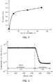
- the insulation resistance curve of the module as a function of the measured crosslinking rate can then be plotted. From this reference curve, it is possible to determine the average rate of crosslinking of an EVA encapsulation film laminated from a photovoltaic module in situ and without damaging the PV module.
- the figure 4 represents the resistance of the EVA as a function of the average rate of crosslinking. Each parameter was measured three times. The value represents the average of 3 measurements. The variation in electrical resistance of the EVA makes it possible to obtain the reference curve and subsequently determine the average rate of crosslinking of a film. encapsulation in laminated EVA of a photovoltaic module in situ and without damaging the PV module.
- the figure 5 represents the dielectric response of an acrylic resin. The measurements were made at 10 Hz, to have a resistive type response. The conductivity of the polymerized resin decreases by two orders of magnitude compared to the non-polymerized resin (liquid formulation).
- the module is not subjected to a UV irradiation step.
- modules with polymerized / crosslinked (converted) resins are subjected to different irradiation times under UV radiation, at a power of 0.5W / cm 2 . For example, five different irradiation times can be achieved.
- the PV module is then disassembled and the resin layer 20 is recovered.
- the average conversion rate is obtained by characterizing the resin by DSC and by determining its glass transition temperature.
- the curve representing the resistance of the resin layer as a function of its average conversion rate can be plotted. From this reference curve, it is possible to determine the average conversion rate a resin layer of a photovoltaic module in situ and without damaging the PV module.
Landscapes
- Health & Medical Sciences (AREA)
- Life Sciences & Earth Sciences (AREA)
- Chemical & Material Sciences (AREA)
- Engineering & Computer Science (AREA)
- Food Science & Technology (AREA)
- Medicinal Chemistry (AREA)
- Physics & Mathematics (AREA)
- Analytical Chemistry (AREA)
- Biochemistry (AREA)
- General Health & Medical Sciences (AREA)
- General Physics & Mathematics (AREA)
- Immunology (AREA)
- Pathology (AREA)
- Photovoltaic Devices (AREA)
Abstract
Procédé de caractérisation du taux moyen de réticulation d'une couche d'encapsulation (20), présente dans un module photovoltaïque, comprenant les étapes successives suivantes :a) fournir un module photovoltaïque comprenant :-une première plaque (10),-une pluralité de cellules photovoltaïques (30), reliées électriquement entre elles,-une couche d'encapsulation (20), encapsulant la pluralité de cellules photovoltaïques (30),-une deuxième plaque (40), la couche d'encapsulation (20) et la pluralité de cellules photovoltaïques (30) étant situées entre les première et deuxième plaques (10, 40),b) recouvrir la première plaque (10) par un élément électriquement conducteur (100),c) mesurer la résistance électrique de la couche d'encapsulation (20) entre la pluralité de cellules photovoltaïques (30) et l'élément électriquement conducteur (100),d) comparer la résistance électrique mesurée avec des valeurs de référence prédéfinies, de manière à déterminer le taux moyen de réticulation de la couche d'encapsulation (20).Method for characterizing the average crosslinking rate of an encapsulation layer (20), present in a photovoltaic module, comprising the following successive steps: a) providing a photovoltaic module comprising: -a first plate (10), - a plurality of photovoltaic cells (30), electrically connected to each other, - an encapsulation layer (20), encapsulating the plurality of photovoltaic cells (30), - a second plate (40), the encapsulation layer (20) and the plurality of photovoltaic cells (30) being located between the first and second plates (10, 40), b) covering the first plate (10) with an electrically conductive element (100), c) measuring the electrical resistance of the layer of encapsulation (20) between the plurality of photovoltaic cells (30) and the electrically conductive element (100), d) comparing the electrical resistance measured with predefined reference values, so as to determine the average rate of crosslinking of the coating e of encapsulation (20).
Description
L'invention se rapporte à un procédé de caractérisation, non destructif, du taux moyen de réticulation d'une couche d'encapsulation, présente dans un module photovoltaïque. L'invention concerne plus particulièrement les modules photovoltaïques comportant des cellules photovoltaïques de type silicium.The invention relates to a non-destructive method for characterizing the average rate of crosslinking of an encapsulation layer, present in a photovoltaic module. The invention relates more particularly to photovoltaic modules comprising photovoltaic cells of the silicon type.
L'invention se rapporte également à un procédé de suivi de la qualité d'un module photovoltaïque.The invention also relates to a method for monitoring the quality of a photovoltaic module.
Le procédé de fabrication d'un module photovoltaïque consiste, classiquement, à empiler, dans un premier temps, les différentes couches constitutives du module :
- une plaque transparente en face avant du module ; la face avant étant celle exposée au rayonnement solaire incident lors de l'implantation des modules sur le terrain,
- une première couche de matériau polymère transparent (premier film encapsulant),
- un ensemble de cellules photovoltaïques interconnectées,
- une deuxième couche de matériau polymère (deuxième film encapsulant),
- une plaque en face arrière du module.
- a transparent plate on the front of the module; the front face being that exposed to incident solar radiation during the installation of the modules in the field,
- a first layer of transparent polymer material (first encapsulating film),
- a set of interconnected photovoltaic cells,
- a second layer of polymeric material (second encapsulating film),
- a plate on the rear of the module.
Les films encapsulants, aussi appelés feuilles ou couches d'encapsulation, sont en général positionnés de part et d'autre des cellules photovoltaïques. Les films encapsulants sont des films solides en un matériau polymère de type élastomère, par exemple, en polyoléfines fonctionnelles réticulables, comme le copolymère d'éthylène et d'acétate de vinyle (EVA).The encapsulating films, also called sheets or encapsulation layers, are generally positioned on either side of the photovoltaic cells. Encapsulating films are solid films made of an elastomeric polymer material, for example, of crosslinkable functional polyolefins, such as the copolymer of ethylene and vinyl acetate (EVA).
Après l'étape d'assemblage, l'ensemble ainsi formé est soumis à une étape de lamination (aussi appelée étape de laminage), permettant de faire fondre puis réticuler les matériaux polymères des films encapsulants. Cette opération est généralement exécutée à l'aide d'un laminateur (aussi appelé laminoir) pouvant être, par exemple, une presse à membrane. Cette opération peut également être réalisée par un autre procédé, par autoclave par exemple. On obtient ainsi des cellules photovoltaïques complètement encapsulées dans une couche d'encapsulation, obtenue à partir des deux films encapsulants. Les cellules sont isolées de l'environnement extérieur et protégées des chocs et des contraintes mécaniques. L'EVA est un matériau thermofusible, mais grâce à la réticulation intervenant lors du procédé de lamination, il devient réticulé. La lamination thermique de l'empilement a également pour conséquence le collage de l'ensemble de la structure.After the assembly step, the assembly thus formed is subjected to a lamination step (also called rolling step), making it possible to melt and then crosslink the polymeric materials of the encapsulating films. This operation is generally carried out using a laminator (also called a rolling mill) which can be, for example, a membrane press. This operation can also be carried out by another method, for example by autoclave. Photovoltaic cells are thus completely encapsulated in an encapsulation layer, obtained from the two encapsulating films. The cells are isolated from the external environment and protected from shocks and mechanical stresses. EVA is a hot-melt material, but thanks to the crosslinking that occurs during the lamination process, it becomes crosslinked. The thermal lamination of the stack also results in the bonding of the entire structure.
L'alternative au procédé de lamination thermique décrit ci-dessus est celle de l'utilisation d'encapsulants sous forme initiale liquide polymérisable qui, pendant l'opération de mise en module photovoltaïque sont capables de se transformer par polymérisation voire réticulation en un matériau solide caoutchoutique souple, protégeant les cellules et assurant le collage ou la cohésion de l'assemblage.The alternative to the thermal lamination process described above is that of using encapsulants in the initial polymerizable liquid form which, during the photovoltaic module operation, are capable of transforming by polymerization or even crosslinking into a solid material. flexible rubber, protecting the cells and ensuring the bonding or cohesion of the assembly.
Il est, par exemple, possible d'utiliser des résines liquides à l'état initial, les résines liquides pouvant être solidifiées avec un apport de chaleur, ou sous rayonnement ultra-violet, comme les résines de type silicone ou acrylique.It is, for example, possible to use liquid resins in the initial state, the liquid resins being able to be solidified with an addition of heat, or under ultra-violet radiation, such as resins of the silicone or acrylic type.
Dans les deux cas, il est indispensable que les matériaux polymères ou les résines formant les couches d'encapsulation soient suffisamment polymérisés et réticulés pour assurer leur fonction d'encapsulation.In both cases, it is essential that the polymer materials or the resins forming the encapsulation layers be sufficiently polymerized and crosslinked to ensure their encapsulation function.
Un faible taux polymérisation/réticulation (aussi appelé taux de conversion) peut mener, par exemple, à des problèmes liés à la présence de monomères ou oligomères non convertis (interaction chimique avec la cellule, dissolution des monomères...), au fluage du matériau polymère et donc à une diminution de la durée de vie du module photovoltaïque.A low polymerization / crosslinking rate (also called conversion rate) can lead, for example, to problems linked to the presence of unconverted monomers or oligomers (chemical interaction with the cell, dissolution of the monomers ...), to the creep of the polymer material and therefore a decrease in the life of the photovoltaic module.
Par exemple, Pern et al. ont montré qu'une réticulation de l'EVA d'au moins 80% permet d'obtenir de bonnes propriétés thermomécaniques et optiques, et une résistance chimique satisfaisante (
Pour une résine, un taux de réticulation d'au moins 95% permet d'obtenir de bonnes propriétés thermomécaniques et optiques, et une résistance chimique (propriété barrière) satisfaisante.For a resin, a crosslinking rate of at least 95% makes it possible to obtain good thermomechanical and optical properties, and satisfactory chemical resistance (barrier property).
Or, le taux de réticulation peut varier en fonction des conditions opérationnelles utilisées (température, pression, durée de l'irradiation ou du chauffage, laminateur, durée de l'étape de laminage, etc) ainsi qu'en fonction du matériau (quantité et nature des agents de réticulation). Il est donc essentiel de pouvoir déterminer le taux de réticulation des couches d'encapsulation obtenues soit par lamination de films encapsulants soit par polymérisation/réticulation d'une résine.However, the crosslinking rate can vary according to the operational conditions used (temperature, pressure, duration of irradiation or heating, laminator, duration of the rolling step, etc.) as well as according to the material (quantity and nature of the crosslinking agents). It is therefore essential to be able to determine the degree of crosslinking of the encapsulation layers obtained either by lamination of encapsulating films or by polymerization / crosslinking of a resin.
Il existe plusieurs méthodes connues permettant d'assurer un suivi de la réaction de réticulation/conversion d'un polymère.There are several known methods for monitoring the crosslinking / conversion reaction of a polymer.
La première méthode est une méthode par extraction de solvant (Soxhlet). Cette méthode est par exemple décrite dans la norme IEC 62788-1-6 (« Procédures de mesure des matériaux utilisés dans les modules photovoltaïques - Partie 1-6 : Encapsulants - Méthodes d'essai pour déterminer le degré de durcissement dans l'éthylène-acétate de vinyle »). Des échantillons de polymère sont prélevés, immergés dans du xylène et suivent des cycles dans le Soxhlet à 140°C, pendant au moins 8h, puis les résidus sont séchés à 115°C pendant au moins 4h. La fraction insoluble est ensuite déterminée.The first method is a solvent extraction method (Soxhlet). This method is for example described in standard IEC 62788-1-6 (“Procedures for measuring materials used in photovoltaic modules - Part 1-6: Encapsulants - Test methods for determining the degree of hardening in ethylene- vinyl acetate ”). Polymer samples are taken, immersed in xylene and follow cycles in the Soxhlet at 140 ° C, for at least 8h, then the residues are dried at 115 ° C for at least 4h. The insoluble fraction is then determined.
Cependant, cette méthode est destructive, particulièrement longue à mettre en œuvre, et utilise des solvants pouvant être toxiques.However, this method is destructive, particularly long to implement, and uses solvents which can be toxic.
Une autre méthode est une méthode par chromatographie gazeuse. Cette méthode a, par exemple, été utilisée par
Il est également possible de déterminer le taux de réticulation par analyse calorimétrique différentielle (ou DSC pour « Differential Scanning Calorimetry »), par spectroscopie Raman ou encore par analyse diélectrique (DEA pour « Dielectric Analysis »).
Cependant, les méthodes existantes sont destructives (nécessité de récupérer un morceau de film encapsulant pour l'analyser), chronophages et/ou coûteuses.However, the existing methods are destructive (need to recover a piece of encapsulating film to analyze it), time-consuming and / or expensive.
Un but de la présente invention est de proposer un procédé de caractérisation du taux moyen de réticulation d'une couche d'encapsulation, présente dans un module photovoltaïque, sans les inconvénients des méthodes précitées, et notamment sans avoir besoin de prélever et de détruire un échantillon de la couche d'encapsulation.An object of the present invention is to provide a method for characterizing the average rate of crosslinking of an encapsulation layer, present in a photovoltaic module, without the drawbacks of the aforementioned methods, and in particular without the need to sample and destroy a sample of the encapsulation layer.
Pour cela, la présente invention propose un procédé de caractérisation du taux moyen de réticulation d'une couche d'encapsulation, présente dans un module photovoltaïque, comprenant les étapes successives suivantes :
- a) fournir un module photovoltaïque comprenant au moins :
- une première plaque,
- une pluralité de cellules photovoltaïques, reliées électriquement entre elles,
- une couche d'encapsulation, encapsulant la pluralité de cellules photovoltaïques,
- une deuxième plaque, la couche d'encapsulation et la pluralité de cellules photovoltaïques étant situées entre les première et deuxième plaques,
- b) recouvrir la première plaque par un élément électriquement conducteur,
- c) mesurer la résistance électrique de la couche d'encapsulation entre la pluralité de cellules photovoltaïques et l'élément électriquement conducteur, avec un appareil de mesure,
- d) comparer la résistance électrique mesurée avec des valeurs de référence prédéfinies, de manière à déterminer le taux moyen de réticulation de la couche d'encapsulation.
- a) provide a photovoltaic module comprising at least:
- a first plate,
- a plurality of photovoltaic cells, electrically connected to each other,
- an encapsulation layer, encapsulating the plurality of photovoltaic cells,
- a second plate, the encapsulation layer and the plurality of photovoltaic cells being located between the first and second plates,
- b) cover the first plate with an electrically conductive element,
- c) measuring the electrical resistance of the encapsulation layer between the plurality of photovoltaic cells and the electrically conductive element, with a measuring device,
- d) comparing the electrical resistance measured with predefined reference values, so as to determine the average rate of crosslinking of the encapsulation layer.
Selon une première variante, la couche d'encapsulation est une couche solide en matériau polymère au moins partiellement réticulée, par exemple, obtenue par lamination d'un ou plusieurs films encapsulants en matériau polymère réticulable. L'étape de lamination permet de faire fondre les films encapsulants et de les faire au moins partiellement réticuler.According to a first variant, the encapsulation layer is a solid layer of at least partially crosslinked polymeric material, for example, obtained by lamination of one or more encapsulating films of crosslinkable polymeric material. The lamination step makes it possible to melt the encapsulating films and to make them at least partially crosslink.
Selon cette première variante, par au moins partiellement réticulé, on entend un taux de réticulation supérieur à 50%, et de préférence supérieur à 75%. La réticulation correspond à la formation de liaisons covalentes entre les chaînes polymères macromoléculaires (ponts de réticulation) créant un réseau tridimensionnel.According to this first variant, by at least partially crosslinked is meant a crosslinking rate greater than 50%, and preferably greater than 75%. Crosslinking corresponds to the formation of covalent bonds between the macromolecular polymer chains (crosslinking bridges) creating a three-dimensional network.
Selon une deuxième variante, la couche d'encapsulation est une couche solide obtenue à partir d'une résine liquide, qui a été au moins partiellement polymérisée et réticulée, par exemple par apport de chaleur et/ou de rayonnements UV. Une résine qui est polymérisée et réticulée est aussi appelée 'résine convertie'.According to a second variant, the encapsulation layer is a solid layer obtained from a liquid resin, which has been at least partially polymerized and crosslinked, for example by adding heat and / or UV radiation. A resin which is polymerized and crosslinked is also called 'converted resin'.
Selon cette deuxième variante, par au moins partiellement polymérisée et réticulée (i.e. par au moins partiellement convertie), on entend un taux de réticulation supérieur à 80%, et de préférence supérieur à 90%. La polymérisation correspond à la formation de chaînes macromoléculaires à partir de monomères, oligomères et/ou pré-polymères, et la réticulation correspond à une formation de liaisons covalentes entre les chaînes macromoléculaires (ponts de réticulation) créant un réseau tridimensionnel. Les deux phénomènes se produisent de manière combinée.According to this second variant, by at least partially polymerized and crosslinked (ie by at least partially converted), is meant a rate of crosslinking greater than 80%, and preferably greater than 90%. Polymerization corresponds to the formation of macromolecular chains from monomers, oligomers and / or pre-polymers, and crosslinking corresponds to a formation of covalent bonds between the macromolecular chains (crosslinking bridges) creating a three-dimensional network. The two phenomena occur in a combined way.
Le procédé de l'invention consiste à mesurer la résistance électrique de la couche d'encapsulation, entre le circuit de cellules photovoltaïques et un contact métallique, positionné à l'extérieur du module photovoltaïque (sur la face avant ou sur la face arrière). La résistance du matériau polymère ou de la résine de la couche d'encapsulation reflète la mobilité des porteurs de charges, qui dépend de la mobilité des chaines macromoléculaires et dépend donc de l'avancement de la réaction de polymérisation/réticulation. Cette mesure diélectrique permet de déterminer le taux de réticulation (aussi appelé taux de conversion, degré de polymérisation/réticulation ou avancement de la polymérisation/réticulation) de la couche d'encapsulation.The method of the invention consists in measuring the electrical resistance of the encapsulation layer, between the photovoltaic cell circuit and a metal contact, positioned outside the photovoltaic module (on the front face or on the rear face). The resistance of the polymer material or of the resin of the encapsulation layer reflects the mobility of the charge carriers, which depends on the mobility of the macromolecular chains and therefore depends on the progress of the polymerization / crosslinking reaction. This dielectric measurement makes it possible to determine the crosslinking rate (also called conversion rate, degree of polymerization / crosslinking or progress of polymerization / crosslinking) of the encapsulation layer.
La mesure est fiable et très rapide (de quelques secondes à quelques minutes).The measurement is reliable and very fast (from a few seconds to a few minutes).
Le procédé est facile à mettre en œuvre et non destructif. Il permet de contrôler directement la réticulation des modules PV sur la ligne de production (« in line »), ou à la fin de la ligne de production (post-fabrication) ou encore d'analyser des modules PV sur le terrain ou revenant du terrain, ce qui n'est pas possible avec les procédés de l'art antérieur. Le procédé selon l'invention permet d'évaluer le taux de réticulation d'un matériau polymère sur un module photovoltaïque terminé.The process is easy to implement and non-destructive. It allows direct control of the crosslinking of PV modules on the production line (“in line”), or at the end of the production line (post-production) or even to analyze PV modules in the field or returning from the field, which is not possible with the methods of the prior art. The method according to the invention makes it possible to evaluate the rate of crosslinking of a polymer material on a completed photovoltaic module.
Avantageusement, le procédé comporte, en outre, après l'étape d), les étapes successives suivantes :
- e) retirer l'élément électriquement conducteur de la première plaque et recouvrir la deuxième plaque avec l'élément électriquement conducteur,
- f) répéter étapes c) et d) telles que définies précédemment.
- e) remove the electrically conductive element from the first plate and cover the second plate with the electrically conductive element,
- f) repeat steps c) and d) as defined above.
Lorsque la couche d'encapsulation est obtenue en laminant deux films encapsulants, disposés de part et d'autre de la pluralité de cellules photovoltaïques, le procédé peut être réalisé sur la face avant et/ou arrière d'un module photovoltaïque. Il peut permettre de vérifier que le taux moyen de réticulation est suffisant en face avant et/ou en face arrière.When the encapsulation layer is obtained by laminating two encapsulating films, arranged on either side of the plurality of photovoltaic cells, the method can be carried out on the front and / or rear face of a photovoltaic module. he can be used to verify that the average rate of crosslinking is sufficient on the front face and / or on the rear face.
Avantageusement, le procédé comporte entre l'étape b) et l'étape c) les étapes suivantes :
- b1) connecter la pluralité de cellules photovoltaïques et l'élément électriquement conducteur, d'une part, à une source de tension ou de courant, et d'autre part, à l'appareil de mesure,
- b2) appliquer une tension ou un courant entre la pluralité de cellules photovoltaïques et l'élément électriquement conducteur.
- b1) connecting the plurality of photovoltaic cells and the electrically conductive element, on the one hand, to a voltage or current source, and on the other hand, to the measuring device,
- b2) applying a voltage or current between the plurality of photovoltaic cells and the electrically conductive element.
Avantageusement, la tension appliquée lors de l'étape b2) est supérieure ou égale à 250V, par exemple 500V ou 1000V, pour avoir une résistance mesurable avec une précision suffisante.Advantageously, the voltage applied during step b2) is greater than or equal to 250V, for example 500V or 1000V, in order to have a resistance that can be measured with sufficient precision.
Avantageusement, le courant ou la tension appliquée lors de l'étape b2) est appliquée pendant une durée d'au moins 30 secondes, et de préférence d'au moins 1 minute. Ceci permet d'atteindre un régime stationnaire.Advantageously, the current or voltage applied during step b2) is applied for a period of at least 30 seconds, and preferably at least 1 minute. This achieves a steady state.
Avantageusement, l'étape b2) est répétée deux fois, par exemple une première fois à une tension de 1000V et une deuxième fois à une tension de 500V, pour éviter de perturber les mesures avec la charge des éléments capacitifs du module photovoltaïque.Advantageously, step b2) is repeated twice, for example a first time at a voltage of 1000V and a second time at a voltage of 500V, to avoid disturbing the measurements with the load of the capacitive elements of the photovoltaic module.
Avantageusement, une pression d'au moins 10Pa est appliquée sur l'élément électriquement conducteur, lors des étapes b2) et c). Le contact entre l'élément électriquement conducteur et la plaque est amélioré.
Avantageusement, le procédé comporte entre l'étape c) et l'étape d) les étapes suivantes :
- c1) débrancher l'appareil de mesure, et
- c2) décharger le module photovoltaïque en court-circuitant des parties électriquement conductrices du module photovoltaïque avec la terre.
Advantageously, between step c) and step d), the method comprises the following steps:
- c1) disconnect the measuring device, and
- c2) discharge the photovoltaic module by short-circuiting electrically conductive parts of the photovoltaic module with earth.
Selon un mode de réalisation avantageux, la couche d'encapsulation est une couche de résine acrylique.According to an advantageous embodiment, the encapsulation layer is a layer of acrylic resin.
Selon un autre mode de réalisation avantageux, la couche d'encapsulation est une couche de résine silicone.According to another advantageous embodiment, the encapsulation layer is a layer of silicone resin.
Selon un autre mode de réalisation avantageux, la couche d'encapsulation comprend et est, avantageusement, constituée par un matériau polymère de type élastomère, par exemple, une polyoléfine fonctionnelle, comme le copolymère d'éthylène et d'acétate de vinyle (EVA) ou un autre copolymère à base d'éthylène.According to another advantageous embodiment, the encapsulation layer comprises and advantageously consists of a polymer material of elastomer type, for example, a functional polyolefin, such as the copolymer of ethylene and vinyl acetate (EVA) or another ethylene-based copolymer.
Selon une variante de réalisation avantageuse, l'élément électriquement conducteur recouvre la pluralité de cellules photovoltaïques. Il est ainsi possible de mesurer la résistance de la partie de la couche encapsulante disposée entre les cellules PV et la plaque recouverte par l'élément électriquement conducteur. On choisira avantageusement un élément électriquement conducteur ayant la même surface que les cellules reliées au générateur de tension/courant et on les disposera en regard l'un de l'autre.According to an advantageous alternative embodiment, the electrically conductive element covers the plurality of photovoltaic cells. It is thus possible to measure the resistance of the part of the encapsulating layer disposed between the PV cells and the plate covered by the electrically conductive element. Advantageously, an electrically conductive element having the same surface as the cells connected to the voltage / current generator will be chosen and they will be placed opposite one another.
Selon cette variante de réalisation avantageuse, l'élément électriquement conducteur peut être une feuille métallique, par exemple une feuille d'aluminium ou de cuivre.According to this advantageous alternative embodiment, the electrically conductive element can be a metal sheet, for example an aluminum or copper sheet.
Selon une autre variante de réalisation avantageuse, l'élément électriquement conducteur est un cadre disposé sur le pourtour du module photovoltaïque.According to another advantageous alternative embodiment, the electrically conductive element is a frame disposed around the periphery of the photovoltaic module.
L'invention concerne également un procédé de suivi qualité d'une ligne de fabrication de modules photovoltaïques, comprenant les étapes successives suivantes :
- i. Assembler au moins :
- une première plaque,
- un premier film d'encapsulation réticulable,
- une pluralité de cellules photovoltaïques, reliées électriquement entre elles,
- un deuxième film d'encapsulation réticulable,
- une deuxième plaque.
- ii. Laminer l'ensemble obtenu à l'étape i, de manière à faire fondre et au moins partiellement réticuler le premier film d'encapsulation réticulable et le deuxième film d'encapsulation réticulable, moyennant quoi on forme un module photovoltaïque ayant une couche d'encapsulation encapsulant la pluralité de cellules photovoltaïques,
- iii. Réaliser le procédé de caractérisation du taux moyen de réticulation de la couche d'encapsulation, telles que définies précédemment, pour suivre la qualité du module photovoltaïque.
- i. Assemble at least:
- a first plate,
- a first crosslinkable encapsulation film,
- a plurality of photovoltaic cells, electrically connected to each other,
- a second crosslinkable encapsulation film,
- a second plate.
- ii. Laminate the assembly obtained in step i, so as to melt and at least partially crosslink the first crosslinkable encapsulation film and the second crosslinkable encapsulation film, whereby a photovoltaic module having an encapsulation layer is formed. encapsulating the plurality of photovoltaic cells,
- iii. Carry out the process for characterizing the average rate of crosslinking of the encapsulation layer, as defined above, to monitor the quality of the photovoltaic module.
Avantageusement, si le taux moyen de réticulation de la couche d'encapsulation est inférieur à une valeur seuil prédéfinie, au moins un des paramètres de la ligne de fabrication du module photovoltaïque, par exemple, choisi parmi la température, la pression et la durée de l'étape de lamination, est modifié.Advantageously, if the average rate of crosslinking of the encapsulation layer is less than a predefined threshold value, at least one of the parameters of the production line of the photovoltaic module, for example, chosen from the temperature, the pressure and the duration of the lamination step is modified.
L'invention concerne également un procédé de suivi qualité d'une ligne de fabrication de modules photovoltaïques, comprenant les étapes successives suivantes :
- i'. assembler au moins:
- une première plaque,
- une couche de formulation liquide polymérisable/réticulable,
- une pluralité de cellules photovoltaïques,
- une deuxième plaque.
- ii'. Faire polymériser/réticuler, la formulation liquide polymérisable/réticulable, moyennant quoi on forme un module photovoltaïque ayant une couche d'encapsulation encapsulant la pluralité de cellules photovoltaïques,
- iii'. Réaliser le procédé de caractérisation du taux moyen de conversion de la couche d'encapsulation, telles que définies précédemment, pour suivre la qualité du module photovoltaïque.
- i ' . assemble at least:
- a first plate,
- a layer of polymerizable / crosslinkable liquid formulation,
- a plurality of photovoltaic cells,
- a second plate.
- ii '. Polymerize / crosslink, the polymerizable / crosslinkable liquid formulation, whereby a photovoltaic module is formed having an encapsulation layer encapsulating the plurality of photovoltaic cells,
- iii '. Carry out the characterization process for the average conversion rate of the encapsulation layer, as defined above, to monitor the quality of the photovoltaic module.
Avantageusement, si le taux moyen de réticulation de la couche d'encapsulation est inférieur à une valeur seuil prédéfinie, au moins un des paramètres de la ligne de fabrication du module photovoltaïque, par exemple, choisi parmi la température, la pression et la durée de l'étape de polymérisation/réticulation, est modifié.Advantageously, if the average rate of crosslinking of the encapsulation layer is less than a predefined threshold value, at least one of the parameters of the production line of the photovoltaic module, for example, chosen from the temperature, pressure and duration of the polymerization / crosslinking step, is changed.
La présente invention sera mieux comprise à la lecture de la description d'exemples de réalisation donnés à titre purement indicatif et nullement limitatif en faisant référence aux dessins annexés sur lesquels :
- La figure la représente, de manière schématique, en vue éclatée, les différents éléments d'un module photovoltaïque, avant une étape de lamination, selon un mode de réalisation particulier de l'invention.
- La
figure 1b représente, de manière schématique, en vue éclatée, les différents éléments d'un module photovoltaïque, après une étape de lamination, selon un mode de réalisation particulier de l'invention. - La
figure 2 représente, de manière schématique, en vue éclatée, un module photovoltaïque, dont la couche d'encapsulation est obtenue à partir d'une résine liquide, selon un mode de réalisation particulier de l'invention. - La
figure 3 représente de manière schématique, le montage électrique pour mesurer la résistance d'une couche d'encapsulation d'un module photovoltaïque, selon un mode de réalisation particulier de l'invention. - La
figure 4 représente la résistance d'une couche d'EVA en fonction du taux moyen de réticulation. - La
figure 5 représente l'évolution de la conductivité d'une formulation acrylique photopolymérisable en fonction du temps sans irradiation UV et sous rayonnement UV. - La
figure 6 représente le taux de conversion mesuré par variation de permittivité en fonction du taux de conversion mesuré par spectroscopie Raman d'une résine époxyde.
- FIG. 1a schematically represents, in exploded view, the various elements of a photovoltaic module, before a lamination step, according to a particular embodiment of the invention.
- The
figure 1b shows schematically, in exploded view, the different elements of a photovoltaic module, after a lamination step, according to a particular embodiment of the invention. - The
figure 2 shows, schematically, in exploded view, a photovoltaic module, the encapsulation layer of which is obtained from a liquid resin, according to a particular embodiment of the invention. - The
figure 3 schematically represents the electrical assembly for measuring the resistance of an encapsulation layer of a photovoltaic module, according to a particular embodiment of the invention. - The
figure 4 represents the resistance of an EVA layer as a function of the average crosslinking rate. - The
figure 5 represents the evolution of the conductivity of a photopolymerizable acrylic formulation as a function of time without UV irradiation and under UV radiation. - The
figure 6 represents the conversion rate measured by variation in permittivity as a function of the conversion rate measured by Raman spectroscopy of an epoxy resin.
Les différentes parties représentées sur les figures ne le sont pas nécessairement selon une échelle uniforme, pour rendre les figures plus lisibles.The different parts shown in the figures are not necessarily shown on a uniform scale, to make the figures more readable.
Les différentes possibilités (variantes et modes de réalisation) doivent être comprises comme n'étant pas exclusives les unes des autres et peuvent se combiner entre elles.The different possibilities (variants and embodiments) must be understood as not being mutually exclusive and can be combined with one another.
On se réfère tout d'abord à la figure la qui représente une vue éclatée de différents éléments que l'on assemble pour fabriquer un module photovoltaïque (PV), selon un mode de réalisation particulier de l'invention. Le module photovoltaïque est obtenu en assemblant :
une première plaque 10, en face avant du module,- une première couche de matériau polymère 21 (premier film encapsulant),
- un ensemble de cellules photovoltaïques 30, par exemple, en silicium, disposées côte à côte, et interconnectées entre elles, par des connections métalliques 31 électriquement conductrices,
- une deuxième couche de matériau polymère 22 (deuxième film encapsulant),
- une deuxième
plaque 40, en face arrière.
- a
first plate 10, on the front face of the module, - a first layer of polymer material 21 (first encapsulating film),
- a set of
photovoltaic cells 30, for example, made of silicon, arranged side by side, and interconnected with one another, by electricallyconductive metal connections 31, - a second layer of polymeric material 22 (second encapsulating film),
- a
second plate 40, on the rear face.
Puis l'ensemble ainsi formé est laminé à chaud.Then the assembly thus formed is hot rolled.
Initialement, c'est-à-dire avant l'opération de lamination, le module comprend, avantageusement, au moins deux films encapsulants 21, 22, entre lesquels la pluralité de cellules photovoltaïques 30 est disposée. Selon une alternative, non représentée, le module pourrait comprendre un seul film d'encapsulation. Selon une autre variante non représentée, le module pourrait comprendre plusieurs films encapsulants disposés en face avant et/ou plusieurs films encapsulants disposés en face arrière.Initially, that is to say before the lamination operation, the module advantageously comprises at least two encapsulating
Les films encapsulants 21, 22 utilisés, lors de l'assemblage, sont des films en matériau polymère réticulable, c'est-à-dire qu'ils sont polymérisés mais non réticulés ou peu réticulés.The encapsulating
Par non réticulés ou peu réticulés, on entend qu'ils ont de préférence un taux de réticulation inférieur ou égal à 5% et de préférence inférieur à 1%.By non-crosslinked or poorly crosslinked is meant that they preferably have a crosslinking rate of less than or equal to 5% and preferably less than 1%.
La réticulation a lieu lors de l'étape de lamination. Après l'opération de lamination, les films encapsulants 21, 22 fondent pour ne former qu'une seule couche 20 dite couche d'encapsulation dans laquelle sont noyées les cellules photovoltaïques 30 (
Avantageusement, la résistivité des films encapsulants 21, 22 varie significativement lors de la réticulation.Advantageously, the resistivity of the encapsulating
Par varie significativement, on entend que la résistivité du matériau réticulé est au moins deux fois et, de préférence, au moins dix fois plus élevée que celle du matériau polymère non réticulé. Elle peut, par exemple, être cent fois plus élevée.By significantly varies, it is meant that the resistivity of the crosslinked material is at least twice and, preferably, at least ten times higher than that of the non-crosslinked polymeric material. It can, for example, be a hundred times higher.
Par matériau polymère, on entend un homopolymère ou un copolymère pouvant éventuellement contenir des additifs.By polymeric material is meant a homopolymer or a copolymer which may optionally contain additives.
Le matériau polymère est, avantageusement, choisi parmi les homopolymères ou les copolymères d'éthylène. Toute polyoléfine réticulable pouvant être laminée pourrait également être utilisée. De préférence, le matériau polymère est de l'EVA.The polymer material is advantageously chosen from homopolymers or copolymers of ethylene. Any crosslinkable polyolefin which can be laminated could also be used. Preferably, the polymeric material is EVA.
Le matériau polymère peut comprendre, en outre, un agent de réticulation, tel qu'un peroxyde, un co-agent ou promoteur de réticulation pour améliorer la cinétique de réaction, un agent de couplage pour améliorer l'adhésion du film sur les plaques avant et arrière ainsi que sur l'ensemble de cellules photovoltaïques interconnectées (par exemple, un silane), un stabilisant UV (molécules capables de piéger des radicaux formés lors du vieillissement UV par recombinaison), et/ou un absorbeur UV tels que les benzophénones, les benzotriazoles, les cyanocrylates et les triazines.The polymeric material may further comprise a crosslinking agent, such as a peroxide, a crosslinking co-agent or promoter to improve the reaction kinetics, a coupling agent to improve the adhesion of the film to the front plates. and rear as well as on the set of interconnected photovoltaic cells (for example, a silane), a UV stabilizer (molecules capable of trapping radicals formed during UV aging by recombination), and / or a UV absorber such as benzophenones, benzotriazoles, cyanocrylates and triazines.
Le premier et le deuxième films encapsulants 21, 22 peuvent être de même nature ou de natures différentes. Au moins le matériau polymère du film encapsulant 21 en face avant est transparent. Par transparent, on entend qu'il laisse passer plus de 70% du rayonnement incident, et de préférence au moins 80%.The first and second encapsulating
Les films encapsulant 21, 22 ont une épaisseur comprise, typiquement, entre 10µm et 5mm, de préférence entre 50nm et 600µm, encore plus préférentiellement entre 200 et 600µm et encore plus préférentiellement entre 400 et 600µm .The films encapsulating 21, 22 have a thickness typically comprised between 10 μm and 5 mm, preferably between 50 nm and 600 μm, even more preferably between 200 and 600 μm and even more preferably between 400 and 600 μm.
Le premier et le deuxième films encapsulants 21, 22 peuvent avoir la même épaisseur ou des épaisseurs différentes.The first and second encapsulating
Les films encapsulants 21, 22 peuvent être maintenus, lors de l'assemblage, sur les cellules photovoltaïques et/ou sur les plaques avant ou arrière grâce à un adhésif sensible à la pression ou à une colle liquide par exemple.The encapsulating
Dans le cadre de la fabrication d'un module photovoltaïque, au moins l'une des plaques qui fera face aux faces actives des cellules photovoltaïques du module est transparente, de sorte à laisser passer le rayonnement électromagnétique. Dans ce mode de réalisation particulier, il s'agit de la première plaque 10, positionnée en face avant. De préférence, la plaque transparente est en verre, ou en polymère, et présente des caractéristiques adaptées à une utilisation dans le domaine photovoltaïque.In the context of the manufacture of a photovoltaic module, at least one of the plates which will face the active faces of the photovoltaic cells of the module is transparent, so as to allow the electromagnetic radiation to pass. In this particular embodiment, it is the
La plaque 40 positionnée en face arrière peut être opaque. Il s'agit, par exemple, d'une feuille multicouche, en polymère blanc, et pouvant contenir une feuille en aluminium.The
La première plaque 10 et la deuxième plaque 40 ont une résistivité inférieure ou égale, respectivement, à la résistivité du premier film encapsulant laminé 21 et à la résistivité du deuxième film encapsulant laminé 22.The
On se réfère à la
une première plaque 10, en face avant du module,- un ensemble de cellules photovoltaïques 30, par exemple, en silicium interconnectées entre elles, par des connections électriquement conductrices,
- une couche d'encapsulation 20 à l'état solide (couche encapsulante), enrobant l'ensemble de cellules photovoltaïques 30,
- une deuxième
plaque 40, en face arrière.
- a
first plate 10, on the front face of the module, - a set of
photovoltaic cells 30, for example, of silicon interconnected with one another, by electrically conductive connections, - an
encapsulation layer 20 in the solid state (encapsulating layer), coating the set ofphotovoltaic cells 30, - a
second plate 40, on the rear face.
La couche d'encapsulation 20 à l'état solide peut être, par exemple, obtenue en venant déposer une formulation visqueuse (pâte), sous forme de « cordons » sur l'une des plaques, puis en la polymérisant (i.e. en la durcissant). Il est également possible d'injecter une formulation à l'état liquide entre les deux plaques puis en la polymérisant.The
La formulation initiale contient au moins les précurseurs de la résine. Par précurseur, on entend des monomères et/ou des oligomères et/ou des pré-polymères menant à la formation de la résine polymériqueThe initial formulation contains at least the precursors of the resin. By precursor is meant monomers and / or oligomers and / or pre-polymers leading to the formation of the polymeric resin
Avantageusement, on choisira une résine 20 dont la résistivité varie significativement entre l'état dit liquide (résine non polymérisée/réticulée) et l'état dit solide (résine polymérisée/réticulée).Advantageously, a
Par varie significativement, on entend que la résistivité à l'état solide est au moins deux fois et, de préférence, au moins dix fois plus élevée que la résistivité de la formulation initiale. Elle peut, par exemple, être cent fois plus élevée.By significantly varies, it is meant that the resistivity in the solid state is at least twice and, preferably, at least ten times higher than the resistivity of the initial formulation. It can, for example, be a hundred times higher.
Selon un premier mode de réalisation avantageux, la résine 20 est une résine durcissable par apport de chaleur.According to a first advantageous embodiment, the
Selon un autre mode de réalisation avantageux, la résine 20 est une résine photopolymérisable.According to another advantageous embodiment, the
Par exemple, la résine est une résine polysiloxane (aussi appelée résine silicone). La résine peut comprendre un mélange de plusieurs polysiloxanes différent. Alternativement, elle peut comprendre un mélange d'un ou plusieurs polysiloxanes avec un ou plusieurs autres polymères (non polysiloxanes). Le composant majoritaire en poids (plus de 50% massique) de la résine est le polysiloxane. Le ou les polysiloxanes de la résine peuvent comprendre des groupements vinyliques et/ou aromatiques tels que des groupes phényle ou benzyle.For example, the resin is a polysiloxane resin (also called silicone resin). The resin may comprise a mixture of several different polysiloxanes. Alternatively, it can comprise a mixture of one or more polysiloxanes with one or more other polymers (non-polysiloxanes). The major component by weight (more than 50% by mass) of the resin is polysiloxane. The polysiloxane (s) of the resin can comprise vinyl and / or aromatic groups such as phenyl or benzyl groups.
De préférence, le polysiloxane est un homopolymère, c'est-à-dire qu'il n'est constitué que d'un seul motif répétitif siloxane. A titre illustratif, il peut s'agir de polydiméthylsiloxane (PDMS)...Preferably, the polysiloxane is a homopolymer, that is to say that it consists of only one repeating siloxane unit. By way of illustration, it may be polydimethylsiloxane (PDMS) ...
La résine polysiloxane peut être obtenue en mélangeant deux formulations, la première contenant un polysiloxilane avec des groupements vinyliques, et la seconde contenant un agent de réticulation siloxane associé à un catalyseur (à base de platine, par exemple). Le mélange des deux formulations déclenche la polymérisation de la résine.The polysiloxane resin can be obtained by mixing two formulations, the first containing a polysiloxilane with vinyl groups, and the second containing a siloxane crosslinking agent combined with a catalyst (based on platinum, for example). The mixture of the two formulations triggers the polymerization of the resin.
Selon un autre exemple, la résine est une résine acrylique. Par résine acrylique, on entend un homopolymère ou un copolymère acrylique ou méthacrylique. La résine liquide utilisée peut être polymérisée et réticulée, par l'action d'un rayonnement ultraviolet et/ou d'un rayonnement visible.According to another example, the resin is an acrylic resin. By acrylic resin is meant a homopolymer or an acrylic or methacrylic copolymer. The liquid resin used can be polymerized and crosslinked, by the action of ultraviolet radiation and / or visible radiation.
La résine peut comprendre, ou être constituée, de polyméthacrylate de méthyle (PMMA), de polyméthacrylate de phényle, de polyméthacrylate de benzyle, de polyméthacrylate d'isobornyle, ou d'un copolymère à base de deux ou plus des monomères méthacrylate de méthyle, méthacrylate de phényle, méthacrylate de benzyle, méthacrylate d'isobornyle. Par exemple, il peut également s'agir d'un copolymère à blocs acryliques.The resin may comprise, or be made up of, polymethyl methacrylate (PMMA), polymethyl phenyl methacrylate, benzyl polymethacrylate, isobornyl polymethacrylate, or a copolymer based on two or more of methyl methacrylate monomers, phenyl methacrylate, benzyl methacrylate, isobornyl methacrylate. For example, it can also be a copolymer with acrylic blocks.
La formulation liquide photopolymérisable utilisée pour réaliser la résine acrylique peut comprendre au moins :
- un ou plusieurs types d'amorceurs photosensibles dont la photolyse génère des espèces réactives qui pourront initier la polymérisation du ou des monomères ;
- un ou plusieurs types de monomères monofonctionnels composés de fonctions réactives et permettant d'ajuster la viscosité du milieu réactionnel ;
- un ou plusieurs types de monomères ou oligomères bi- ou polyfonctionnels, souvent téléchéliques (les fonctions réactives en polymérisation se présentent dans les extrémités des molécules) permettant la réticulation du polymère.
- one or more types of photosensitive initiators whose photolysis generates reactive species which can initiate the polymerization of the monomer (s);
- one or more types of monofunctional monomers composed of reactive functions and making it possible to adjust the viscosity of the reaction medium;
- one or more types of bi- or polyfunctional monomers or oligomers, often telechelic (the reactive functions in polymerization occur in the ends of the molecules) allowing the crosslinking of the polymer.
La formulation liquide comprend, par exemple, un mélange de monomères (méth)acryliques, d'oligomères fonctionnalisés avec des groupes (méth)acryliques et des photo-amorceurs.The liquid formulation comprises, for example, a mixture of (meth) acrylic monomers, oligomers functionalized with (meth) acrylic groups and photoinitiators.
La formulation liquide peut comporter, en outre, des additifs modifiant la rhéologie de la résine liquide, par exemple des charges organiques ou inorganiques, et/ou des additifs modifiant les propriétés de mouillage de la résine liquide, par exemple des tensioactifs.The liquid formulation may also contain additives which modify the rheology of the liquid resin, for example organic or inorganic fillers, and / or additives which modify the wetting properties of the liquid resin, for example surfactants.
La couche d'encapsulation 20 à l'état solide est, avantageusement, transparente. Par transparente, on entend qu'elle laisse passer plus de 70% du rayonnement incident, et de préférence au moins 80%.The
La couche d'encapsulation 20 à l'état solide a une épaisseur comprise, typiquement, entre 10µm et 5mm, de préférence entre 50µm et 600µm, encore plus préférentiellement entre 200 et 600µm et encore plus préférentiellement entre 300 et 600µm .The
Dans le cadre de la fabrication d'un module photovoltaïque, au moins l'une des plaques qui fera face aux faces actives des cellules photovoltaïques du module est transparente, de sorte à laisser passer le rayonnement électromagnétique. Dans ce mode de réalisation particulier, il s'agit de la première plaque 10, positionnée en face avant. De préférence, la plaque transparente est en verre, ou en polymère, et présente des caractéristiques adaptées à une utilisation dans le domaine photovoltaïque.In the context of the manufacture of a photovoltaic module, at least one of the plates which will face the active faces of the photovoltaic cells of the module is transparent, so as to allow the electromagnetic radiation to pass. In this particular embodiment, it is the
Avantageusement, pour la mise en œuvre de modules PV avec des résines liquides à durcir, on utilisera des plaques avant et arrière rigides par exemple en verre.Advantageously, for the implementation of PV modules with liquid resins to be hardened, rigid front and rear plates, for example made of glass, will be used.
Afin de réaliser le procédé, la première plaque 10 et la deuxième plaque 40 ont, avantageusement, une résistivité inférieure ou égale à la résistivité de la couche d'encapsulation 20 et de la formulation liquide correspondante.In order to carry out the process, the
Pour les deux modes d'assemblage précédemment décrits, les cellules photovoltaïques 30 peuvent être bi-faciales, et les première et deuxième plaques 10, 40 sont transparentes au rayonnement solaire incident.For the two assembly methods described above, the
Les cellules photovoltaïques 30 peuvent être reliées électriquement en série par des connecteurs électriquement conducteurs 31 destinés à collecter l'électricité générée par les cellules photovoltaïques. Les connecteurs électriquement conducteurs 31 sont des connections métalliques, par exemple il s'agit de rubans ou de fils en cuivre. Les cellules sont, avantageusement, régulièrement espacées. Les cellules sont, par exemple, sous la forme de fines plaques d'environ 200µm d'épaisseur. Il y a par exemple 60 cellules dans un module PV. L'ensemble formé par les cellules photovoltaïques 30 et les connecteurs 31 forme un squelette de cellules photovoltaïques.The
Le module photovoltaïque peut également comprendre une boite de jonction 50 (ou boite de dérivation) raccordant les connections métalliques 31 du circuit de cellules photovoltaïques 30, et, éventuellement, un cadre en aluminium 60, comme par exemple représenté sur la
Le procédé de caractérisation comprend les étapes successives suivantes :
- a) fournir un module photovoltaïque tel que défini précédemment,
- b) recouvrir une des
plaques plaque 10 en face avant, par un élément électriquement conducteur 100, - c) mesurer la résistance électrique de la couche d'encapsulation 20, avec un appareil de mesure,
- d) comparer la résistance électrique mesurée avec des valeurs de référence de modules de même configuration (dimensions, matériaux, etc) de manière à déterminer le taux moyen de réticulation de la couche d'encapsulation 20.
- a) supply a photovoltaic module as defined above,
- b) cover one of the
plates plate 10 on the front face, by an electricallyconductive element 100, - c) measuring the electrical resistance of the
encapsulation layer 20, with a measuring device, - d) compare the electrical resistance measured with reference values of modules of the same configuration (dimensions, materials, etc.) so as to determine the average rate of crosslinking of the
encapsulation layer 20.
Le procédé comprend, de préférence, entre l'étape b) et l'étape c), les étapes suivantes :
- b1) connecter la pluralité de cellules 30 et l'élément électriquement conducteur 100, d'une part, à une
source 200 de tension ou de courant, et d'autre part, à un appareil de mesure, - b2) appliquer une tension ou un courant entre la pluralité de cellules 30 et l'élément électriquement conducteur 100.
- b1) connecting the plurality of
cells 30 and the electricallyconductive element 100, on the one hand, to asource 200 of voltage or current, and on the other hand, to a measuring device, - b2) applying a voltage or current between the plurality of
cells 30 and the electricallyconductive element 100.
Le taux moyen de réticulation correspond au taux de réticulation mesuré dans un volume de la couche d'encapsulation 20. Le volume est situé entre les cellules 30 connectées au générateur de tension 200 (et à l'appareil de mesure) et l'élément électriquement conducteur 100. Le taux peut varier localement dans ce volume (dans le cas d'un matériau bien réticulé, on peut observer généralement une variation de moins de 10 %). Il peut varier, par exemple, si la répartition des agents de réticulation est inhomogène dans le film encapsulant 21, 22 ou, dans le cas d'une résine, si la répartition des différents composants de la formulation est inhomogène, ou encore si la température ou l'irradiation n'est pas homogène.The average crosslinking rate corresponds to the crosslinking rate measured in a volume of the
Le taux moyen de réticulation est, dans le cadre de l'invention, déterminé in situ, à partir de la mesure d'une grandeur électrique.The average crosslinking rate is, in the context of the invention, determined in situ, from the measurement of an electrical quantity.
Lorsque l'on mesure le taux moyen de réticulation de la couche d'encapsulation 20 entre la plaque 10, en face avant, et la pluralité de cellules photovoltaïques 300, ceci correspond au taux moyen de réticulation du premier film encapsulant laminé, en face avant.When measuring the average rate of crosslinking of the
Les étapes b) à d) peuvent ensuite être répétées, sur l'autre face du module photovoltaïque. Dans ce mode de réalisation, il s'agit de la face arrière. Cela permet de déterminer également le taux moyen de réticulation du film encapsulant laminé, positionné en face arrière ou le taux moyen de réticulation de la couche d'encapsulation 20, obtenue à partir d'une résine liquide, en face arrière. Les taux moyens de réticulation en face avant et en face arrière peuvent être identiques ou différents. Le même élément électriquement conducteur 100 peut être utilisé ou un autre élément électriquement conducteur.Steps b) to d) can then be repeated, on the other face of the photovoltaic module. In this embodiment, it is the rear face. This also makes it possible to determine the average rate of crosslinking of the laminated encapsulating film, positioned on the rear face or the average rate of crosslinking of the
L'élément électriquement conducteur 100 est, par exemple, une feuille d'aluminium ou de cuivre. L'élément électriquement conducteur 100 a une épaisseur allant de 8 à 150µm par exemple. La surface de l'élément électriquement conducteur 100 est avantageusement identique à celle des cellules photovoltaïques 300 connectées au générateur 200 de tension/courant et à l'appareil de mesure. Par exemple, la surface de l'élément électriquement conducteur 100 peut recouvrir la totalité de la surface des cellules 30. L'élément électriquement conducteur 100 est, de préférence, à une distance minimale de 1 mm, préférentiellement de 10 mm à 15 mm, du cadre ou du bord du module PV. Avantageusement, on dispose une charge, par exemple, d'au moins 10Pa, et de préférence d'au moins 30Pa sur l'élément électriquement conducteur 100, de manière à améliorer le contact entre celui-ci et la plaque du module PV.The electrically
Alternativement, le cadre du module 60, recouvrant le pourtour de la plaque 10 en face avant pourrait être utilisé comme élément électriquement conducteur pour remplacer la feuille conductrice.Alternatively, the frame of the
Lors de l'étape c), les cellules PV 300 et l'élément électriquement conducteur 100 sont reliés à la fois à un appareil configuré pour délivrer une grandeur électrique, comme un courant ou une tension, et à un appareil de lecture permettant de déterminer directement ou indirectement la valeur de la résistance de la couche d'encapsulation 20. Par exemple, il s'agit d'un voltmètre ou d'un ampèremètre, ou encore d'un ohmmètre.During step c), the PV cells 300 and the electrically
À titre illustratif, la
Les cellules PV 300 sont préférentiellement connectées à la borne positive du générateur 200 de tension/courant. Toutes les cellules ou seulement une partie des cellules peuvent être reliées, par exemple, un tiers des cellules. La borne négative du générateur 200 est préférentiellement reliée à l'élément électriquement conducteur 100. Le générateur 200 est, par exemple, un testeur d'isolement électrique. Dans le cas d'un module PV ayant un cadre 60, le cadre du module 60 est, avantageusement, connecté à la garde du testeur d'isolement pour éviter que le courant aille dans le cadre du module 60. Alternativement, il est possible de recouvrir les bords du module d'une feuille conductrice et de la connecter à la garde du testeur d'isolement.The PV cells 300 are preferably connected to the positive terminal of the voltage /
Lors de l'étape b2), on applique une tension (ou un courant) entre les bornes positive et négative, à travers la couche encapsulante 20. Avantageusement, la tension est d'au moins 250V, par exemple 500V ou 1000V. Dans le cas d'un courant, on choisira un courant de l'ordre du µA. La tension ou le courant sont adaptés en fonction de la surface du module. On applique, avantageusement, la tension ou le courant progressivement. Par exemple, pour une tension, on choisira 500 V/s. Avantageusement, la tension ou le courant est appliqué pendant une durée d'au moins une minute, par exemple deux minutes, avant de mesurer la résistance du film encapsulant laminé, de manière à avoir un régime stable. L'étape b2) peut être répétée plusieurs fois à différentes tensions ou différents courants. Par exemple, elle peut être répétée deux fois. Par exemple, pour un module de taille standard 1,6m2 (module de 60 cellules), la tension est répétée une première fois à une tension de 1000V et une seconde fois à une tension de 500V. La tension ou le courant sont adaptés à la surface du module. La répétition de l'étape d) permet d'avoir un procédé plus fiable et d'éviter l'influence des éléments capacitifs du module. Avantageusement, entre chaque valeur de tension appliquée, la tension est coupée, et le module déchargé en court-circuitant les bornes du test.During step b2), a voltage (or current) is applied between the positive and negative terminals, through the
Lors de l'étape d) la résistance est déterminée à partir d'une grandeur électrique (tension ou courant). Pour cela, un appareil de lecture du courant ou de tension, par exemple avec un voltmètre, peut être utilisé. Il est également possible de déterminer une autre grandeur électrique, comme la résistivité et la conductivité.During step d) the resistance is determined from an electrical quantity (voltage or current). For this, a device for reading current or voltage, for example with a voltmeter, can be used. It is also possible to determine another electrical quantity, such as resistivity and conductivity.
La valeur ainsi obtenue est comparée avec des données dites de référence. Les valeurs de référence sont prédéfinies et forment des abaques pour un matériau donné. Les valeurs de référence représentent la résistance, la résistivité ou la conductivité en fonction du taux de réticulation pour un matériau donné. Le taux de réticulation peut être déterminé, préalablement, par analyse calorimétrique différentielle (DSC) par exemple.The value thus obtained is compared with so-called reference data. The reference values are predefined and form charts for a given material. The reference values represent resistance, resistivity or conductivity as a function of the crosslinking rate for a given material. The crosslinking rate can be determined beforehand by differential scanning calorimetry (DSC) for example.
On estime que les matériaux polymères laminés sont suffisamment réticulés, pour des applications PV, si le taux moyen de réticulation est supérieur à 60%, et de préférence supérieur à 75%, par exemple pour un taux moyen de réticulation compris entre 60% et 90%, et de préférence compris entre 75% et 85%.It is estimated that the laminated polymeric materials are sufficiently crosslinked, for PV applications, if the average crosslinking rate is greater than 60%, and preferably greater than 75%, for example for an average crosslinking rate between 60% and 90 %, and preferably between 75% and 85%.
On estime que les matériaux polymères, obtenus à partir d'une résine liquide, sont suffisamment polymérisés/réticulés, pour des applications PV, si le taux moyen réticulation est supérieur à 95%, et de préférence supérieur à 98%.It is estimated that the polymer materials, obtained from a liquid resin, are sufficiently polymerized / crosslinked, for PV applications, if the average crosslinking rate is greater than 95%, and preferably greater than 98%.
À la fin du procédé, la tension est coupée, et le module déchargé en court-circuitant les bornes du test.At the end of the process, the voltage is cut, and the module discharged by short-circuiting the terminals of the test.
Avantageusement, le procédé est réalisé à température ambiante (de l'ordre de 20-25°C) et à pression ambiante (de l'ordre de 1bar). On choisira, par exemple, une humidité relative inférieure à 55%. Avantageusement, toutes les mesures sont réalisées dans les mêmes conditions environnementales.Advantageously, the process is carried out at ambient temperature (around 20-25 ° C) and at ambient pressure (around 1 bar). For example, a relative humidity below 55% will be chosen. Advantageously, all the measurements are carried out under the same environmental conditions.
En fonction des valeurs obtenues, il est également possible de modifier les paramètres de la chaine de fabrication pour la fabrication des modules photovoltaïques suivants.Depending on the values obtained, it is also possible to modify the parameters of the production chain for the manufacture of the following photovoltaic modules.
En particulier, il est possible de modifier les paramètres liés à l'étape de réticulation des matériaux destinés à former la couche d'encapsulation.In particular, it is possible to modify the parameters linked to the crosslinking step of the materials intended to form the encapsulation layer.
Dans le cas d'une couche d'encapsulation 20 obtenue par laminage de film(s) encapuslant(s), il est, par exemple, possible d'augmenter la température ou la durée de l'étape de lamination. La fabrication des modules est ainsi optimisée.In the case of an
Dans le cas d'une couche d'encapsulation 20 obtenue à partir d'une résine liquide, si le taux moyen de réticulation ainsi déterminé est inférieur à une valeur seuil prédéterminée, il est possible de soumettre le module PV à une nouvelle étape de polymérisation, sous irradiation UV ou par un apport de chaleur par exemple. La nouvelle étape de polymérisation peut être réalisée avec les mêmes paramètres ou avec des paramètres différents. Il est, par exemple, possible d'augmenter la température, la puissance de l'irradiation ou la durée de l'étape de polymérisation. Le taux moyen de réticulation de la couche d'encapsulation 20 peut ensuite être de nouveau déterminé. Ces étapes (détermination du taux de réticulation puis polymérisation) peuvent être répétées jusqu'à obtenir un taux de réticulation supérieur à la valeur seuil prédéfinie.In the case of an
Avec un tel procédé, il est également possible de suivre sur le site de production l'avancement de la polymérisation/réticulation de la couche d'encapsulation 20, par exemple, en fonction du temps suite à la lamination du module, et donc la qualité du module photovoltaïque au cours de sa fabrication ou avant sa sortie du site de production.With such a process, it is also possible to monitor the progress of the polymerization / crosslinking of the
Il est également possible de récupérer des modules PV ayant déjà servi, et présentant des défaillances, afin de vérifier le taux moyen de réticulation de la couche d'encapsulation. Ceci permet de réaliser un diagnostic et de vérifier si la défaillance provient des couches d'encapsulation des modules PV ou d'un autre élément. Ceci peut être utile, par exemple, si l'on constate que les plaques en face avant et arrière présentent un décalage ou dans le cas de réactions dues à des précurseurs résiduels.It is also possible to recover PV modules which have already been used, and which exhibit failures, in order to check the average rate of crosslinking of the encapsulation layer. This makes it possible to carry out a diagnosis and to check whether the failure comes from the encapsulation layers of the PV modules or of another element. This can be useful, for example, if it is observed that the plates on the front and rear face have an offset or in the case of reactions due to residual precursors.
Exemples illustratifs et non limitatifs d'un mode de réalisation : Illustrative and nonlimiting examples of an embodiment :
Différents modules contenant de l'EVA, à 33 % d'acétate de vinyle, ont été assemblés. Les modules comprennent un empilement comprenant successivement :
une plaque 10 en verre (3 mm d'épaisseur),- une feuille d'encapsulant 21 d'EVA de 450µm d'épaisseur,
- un squelette de cellules interconnectées 30,
- une deuxième feuille d'encapsulant 22 d'EVA de 450µm d'épaisseur,
- une plaque 40 (« backsheet ») de type TPT de 330 µm d'épaisseur.
- a glass plate 10 (3 mm thick),
- a sheet of
encapsulant 21 of EVA 450 μm thick, - a skeleton of
interconnected cells 30, - a second sheet of
encapsulant 22 of EVA 450 μm thick, - a plate 40 (“backsheet”) of TPT type 330 μm thick.
Les modules sont ensuite laminés à des temps différents dans un laminateur industriel de la société 3S, modèle S1815E. Le laminateur est un laminateur à deux chambres, une chambre supérieure et une chambre inférieure, séparées par une membrane souple. L'empilement est placé dans la chambre inférieure, chauffée par le bas par un plateau chaud. Après une première phase de dégazage pendant laquelle du vide est appliqué aux deux chambres, la chambre supérieure est remise à pression atmosphérique, ce qui a pour effet de venir plaquer la membrane souple qui sépare les deux chambres, contre l'empilement.The modules are then laminated at different times in an industrial laminator from the company 3S, model S1815E. The laminator is a laminator with two chambers, an upper chamber and a lower chamber, separated by a flexible membrane. The stack is placed in the lower chamber, heated from below by a hot plate. After a first degassing phase during which vacuum is applied to the two chambers, the upper chamber is returned to atmospheric pressure, which has the effect of pressing the flexible membrane which separates the two chambers against the stack.
Pour obtenir un module ayant des films non réticulés (taux moyen de réticulation de 0%, ou proche de 0%), le module est laminé à basse température, par exemple selon le cycle de lamination suivant :
- 4 à 5 min de dégazage avec le module en contact avec la plaque chauffant,
- 7 à 8 min sous 1000mbar,
- température de la plaque chauffante du laminateur à 100°C.
- 4 to 5 min of degassing with the module in contact with the heating plate,
- 7 to 8 min under 1000mbar,
- temperature of the heating plate of the laminator at 100 ° C.
Pour obtenir un module ayant des films très réticulés (taux moyen de réticulation de 80%), le module est laminé avec un traitement thermique plus important en termes de température et de durée, selon par exemple le cycle de lamination suivant :
- 4 à 5 min de dégazage avec le module en contact avec la plaque chauffante,
- 30 min de réticulation sous 1000mbar,
- température de la plaque chauffante du laminateur à 160°C.
- 4 to 5 min of degassing with the module in contact with the heating plate,
- 30 min of crosslinking under 1000mbar,
- temperature of the laminator hot plate at 160 ° C.
La mesure de résistance électrique des différents modules est réalisée, en face avant du module, à température de 21,7°C et à une humidité relative 43%, selon le procédé suivant :
- connecter les deux bornes du module en court-circuit à la borne positive d'un testeur d'isolement électrique,
- appliquer une feuille électriquement conductrice 100 (une feuille d'aluminium ou de cuivre de 8 µm à 150 µm) sur la face avant du module, de manière recouvrir à 100% la surface des cellules 300, la feuille électriquement conductrice 100 étant distante du
cadre 60 du module d'au moins 1 mm, préférentiellement de 10 mm à 15 mm, - appliquer une charge homogène, de préférence d'au moins 30 Pa, sur la surface conductrice,
- connecter cette feuille conductrice 100 à la borne négative du testeur 200 d'isolement électrique,
- connecter le
cadre 60 du module à la garde du testeur 200 d'isolement, -appliquer progressivement (à 500 V/s) une tension de 3000V pendant 2 minutes puis mesurer la résistance électrique, - une fois la tension coupée, décharger le module en court-circuitant les bornes du test puis enlever le court-circuit.
- connect the two terminals of the short-circuited module to the positive terminal of an electrical insulation tester,
- apply an electrically conductive sheet 100 (an aluminum or copper sheet of 8 μm to 150 μm) on the front face of the module, so as to cover 100% of the surface of the cells 300, the electrically
conductive sheet 100 being distant from theframe 60 of the module at least 1 mm, preferably from 10 mm to 15 mm, - apply a homogeneous load, preferably at least 30 Pa, on the conductive surface,
- connect this
conductive sheet 100 to the negative terminal of theelectrical insulation tester 200, - connect the
frame 60 of the module to the guard of theinsulation tester 200, -apply gradually (at 500 V / s) a voltage of 3000V for 2 minutes then measure the electrical resistance, - once the voltage has been cut, discharge the module by short-circuiting the test terminals then remove the short-circuit.
Un morceau de feuille d'EVA réticulée est ensuite récupéré sur le module PV et caractérisée par DSC.A piece of crosslinked EVA sheet is then recovered from the PV module and characterized by DSC.
La courbe de résistance d'isolation du module en fonction du taux de réticulation mesuré peut ensuite être tracée. A partir de cette courbe de référence, il est possible de déterminer le taux moyen de réticulation d'un film d'encapsulation en EVA laminé d'un module photovoltaïque in situ et sans détériorer le module PV.The insulation resistance curve of the module as a function of the measured crosslinking rate can then be plotted. From this reference curve, it is possible to determine the average rate of crosslinking of an EVA encapsulation film laminated from a photovoltaic module in situ and without damaging the PV module.
La
La
Les conversions mesurées par spectroscopie diélectrique et celles mesurées par spectroscopie Raman ont été tracées l'une en fonction de l'autre (
Différents modules PV contenant une couche d'encapsulation 20 obtenue à partir d'une résine acrylique ont été assemblés. Les modules comprennent un empilement comprenant successivement :
une plaque 10 en verre (3mm d'épaisseur)- une couche de résine 20 silicone de 450µm d'épaisseur finale,
- un squelette de cellules interconnectées 30,
- une autre plaque de verre 40.
- a glass plate 10 (3mm thick)
- a layer of
silicone resin 20 with a final thickness of 450 μm, - a skeleton of
interconnected cells 30, - another
glass plate 40.
Pour obtenir une résine encapsulante non polymérisée/réticulée (non convertie), le module n'est pas soumis à une étape d'irradiation UV.To obtain an encapsulating resin which is not polymerized / crosslinked (not converted), the module is not subjected to a UV irradiation step.
Pour obtenir des modules avec des résines polymérisées/réticulées (converties), les modules sont soumis à différentes durées d'irradiation sous rayonnement UV, sous une puissance de 0,5W/cm2. Par exemple, il est possible de réaliser cinq durées d'irradiation différentes.To obtain modules with polymerized / crosslinked (converted) resins, the modules are subjected to different irradiation times under UV radiation, at a power of 0.5W / cm 2 . For example, five different irradiation times can be achieved.
La mesure de résistance électrique des différents modules est réalisée, en face avant du module, à température de 21,7 °C et à une humidité relative 43%, selon le procédé suivant :
- connecter les deux bornes du module en court-circuit à la borne positive d'un testeur d'isolement électrique,
- appliquer une feuille conductrice 100 (une feuille d'aluminium ou de cuivre de 8 µm à 150 µm) sur la face avant du module, de manière recouvrir à 100% la surface des cellules 30, la feuille conductrice 100 étant distante du cadre du module d'au moins 1 mm, préférentiellement de 10mm à 15mm,
- appliquer une charge homogène, de préférence d'au moins 30 Pa, sur la feuille conductrice 100,
- connecter cette feuille conductrice 100 à la borne négative du testeur d'isolement électrique,
- connecter le cadre du module à la garde du testeur d'isolement,
- appliquer progressivement (à 500 V/s) une tension de 3000V pendant 2 minutes puis mesurer la résistance électrique,
- une fois la tension coupée, décharger le module en court-circuitant les bornes du test puis enlever le court-circuit.
- connect the two terminals of the short-circuited module to the positive terminal of an electrical insulation tester,
- apply a conductive sheet 100 (an aluminum or copper sheet of 8 μm to 150 μm) on the front face of the module, so as to cover 100% of the surface of the
cells 30, theconductive sheet 100 being distant from the frame of the module at least 1 mm, preferably 10mm to 15mm, - applying a homogeneous load, preferably at least 30 Pa, to the
conductive sheet 100, - connect this
conductive sheet 100 to the negative terminal of the electrical insulation tester, - connect the module frame to the guard of the insulation tester,
- gradually apply (at 500 V / s) a voltage of 3000 V for 2 minutes then measure the electrical resistance,
- once the voltage has been cut, discharge the module by short-circuiting the test terminals then remove the short-circuit.
Le module PV est ensuite désassemblé et la couche de résine 20 est récupérée. Le taux moyen de conversion est obtenu en caractérisant la résine par DSC et en déterminant sa température de transition vitreuse.The PV module is then disassembled and the
À partir de ces données, la courbe représentant la résistance de la couche de résine en fonction de son taux moyen de conversion peut être tracée. A partir de cette courbe de référence, il est possible de déterminer le taux moyen de conversion d'une couche de résine d'un module photovoltaïque in situ et sans détériorer le module PV.From this data, the curve representing the resistance of the resin layer as a function of its average conversion rate can be plotted. From this reference curve, it is possible to determine the average conversion rate a resin layer of a photovoltaic module in situ and without damaging the PV module.
Claims (17)
Applications Claiming Priority (2)
| Application Number | Priority Date | Filing Date | Title |
|---|---|---|---|
| FR1873661A FR3090882B1 (en) | 2018-12-20 | 2018-12-20 | METHOD OF CHARACTERIZATION OF THE RATE OF CONVERSION OF AN ENCAPSULATION LAYER OBTAINED FROM A LIQUID RESIN, PRESENT IN A PHOTOVOLTAIC MODULE |
| FR1873667A FR3090883B1 (en) | 2018-12-20 | 2018-12-20 | Method for characterizing the average rate of crosslinking of an encapsulation layer, present in a photovoltaic module |
Publications (2)
| Publication Number | Publication Date |
|---|---|
| EP3672067A1 true EP3672067A1 (en) | 2020-06-24 |
| EP3672067B1 EP3672067B1 (en) | 2021-07-28 |
Family
ID=68848209
Family Applications (1)
| Application Number | Title | Priority Date | Filing Date |
|---|---|---|---|
| EP19217035.5A Active EP3672067B1 (en) | 2018-12-20 | 2019-12-17 | Method for characterizing the average crosslinking rate of an encapsulation layer in a photovoltaic module |
Country Status (1)
| Country | Link |
|---|---|
| EP (1) | EP3672067B1 (en) |
Citations (2)
| Publication number | Priority date | Publication date | Assignee | Title |
|---|---|---|---|---|
| GB2158255A (en) * | 1984-05-02 | 1985-11-06 | Gerald Edward Wardell | Measuring the ac electrical conductance of a polymeric composite |
| DE102009026062A1 (en) * | 2009-06-29 | 2010-12-30 | Schott Solar Ag | Device for detecting changes in properties of material, particularly polymer material, ehtylenvinylacetate or silicone rubber, has discharge pipes, which emits ultraviolet radiation and is arranged in test environment like in test room |
-
2019
- 2019-12-17 EP EP19217035.5A patent/EP3672067B1/en active Active
Patent Citations (2)
| Publication number | Priority date | Publication date | Assignee | Title |
|---|---|---|---|---|
| GB2158255A (en) * | 1984-05-02 | 1985-11-06 | Gerald Edward Wardell | Measuring the ac electrical conductance of a polymeric composite |
| DE102009026062A1 (en) * | 2009-06-29 | 2010-12-30 | Schott Solar Ag | Device for detecting changes in properties of material, particularly polymer material, ehtylenvinylacetate or silicone rubber, has discharge pipes, which emits ultraviolet radiation and is arranged in test environment like in test room |
Non-Patent Citations (3)
| Title |
|---|
| "EVA encapsulants for PV modules: Reliability issues and current R&D status at NREL", RENEWABLE ENERGY, vol. 8, no. 1-4, 1996, pages 367 |
| HARDIS ET AL.: "Cure kinetics characterization and monitoring of an epoxy resin using DSC, Raman spectroscopy, and DEA", COMPOS. PART APPL. SCI. MANUF., vol. 49, 2013, pages 100 - 108 |
| XIANG ET AL.: "Preparation, Characterization and Application of UV-Curable Flexible Hyperbranched Polyurethane Acrylate", POLYMERS, vol. 9, 2017, pages 552, XP055554914, DOI: 10.3390/polym9110552 |
Also Published As
| Publication number | Publication date |
|---|---|
| EP3672067B1 (en) | 2021-07-28 |
Similar Documents
| Publication | Publication Date | Title |
|---|---|---|
| El Amrani et al. | Solar module fabrication | |
| US20100126560A1 (en) | Photovoltaic module comprising a polymer film and process for manufacturing such a module | |
| TW200905902A (en) | Method for making a solar battery module set | |
| EP2671930A1 (en) | Adhesive for solar cell back sheet | |
| Yamamoto et al. | Charge generation and recombination in fullerene-attached poly (3-hexylthiophene)-based diblock copolymer films | |
| EP3164452B1 (en) | Encapsulant of a photovoltaic module | |
| JP2022159549A (en) | Photovoltaic module, photovoltaic encapsulant and method for producing photovoltaic module | |
| EP3672067B1 (en) | Method for characterizing the average crosslinking rate of an encapsulation layer in a photovoltaic module | |
| WO1998035393A1 (en) | Polymer semiconductor device comprising at least a rectifying function and method for making same | |
| EP3028360B1 (en) | Photovoltaic power plants connected to a high voltage electrical network | |
| FR2616969A1 (en) | METHOD FOR MANUFACTURING AN ELECTROCHEMICAL ASSEMBLY COMPRISING AN ELECTRODE AND AN ELECTROLYTE AND THE ASSEMBLY PRODUCED THEREBY | |
| FR3090882A1 (en) | PROCESS FOR CHARACTERIZING THE CONVERSION RATE OF AN ENCAPSULATION LAYER OBTAINED FROM A LIQUID RESIN, PRESENT IN A PHOTOVOLTAIC MODULE | |
| FR3090883A1 (en) | Method for characterizing the average crosslinking rate of an encapsulation layer, present in a photovoltaic module | |
| EP3853910A1 (en) | Flexible laminate of photovoltaic cells and associated production method | |
| EP3353816B1 (en) | Method for producing a photovoltaic module | |
| WO2020120908A1 (en) | Method for manufacturing a photovoltaic module | |
| EP3360174B1 (en) | Adhesive, the precursor of which is applied in liquid form and uv-polymerized, for encapsulating flexible electronic devices, improving the protection against gas permeability | |
| EP3622560B1 (en) | Method for determining a delay in the crystallisation of a thermoplastic polymer, use of such a polymer for coating or encapsulating an electronic component, and associated method | |
| FR3024591A1 (en) | METHOD FOR MANUFACTURING A PHOTOVOLTAIC PANEL | |
| Desai et al. | Assessment of the effect of accelerated ultraviolet aging on mini‐PV modules encapsulated with different poly (ethylene‐co‐vinyl acetate) formulations | |
| Ayad et al. | Photo-stability of the photons converter applied in the photovoltaic conversion systems | |
| EP4055634B1 (en) | Method for manufacturing a photovoltaic module with partial crosslinking and lamination | |
| WO2021008947A1 (en) | Laminate of photovoltaic cells and associated production method | |
| WO2023205839A1 (en) | Method of producing monograin membranes | |
| WO2021123524A1 (en) | Method for fabricating and inspecting a photovoltaic assembly with partial crosslinking |
Legal Events
| Date | Code | Title | Description |
|---|---|---|---|
| PUAI | Public reference made under article 153(3) epc to a published international application that has entered the european phase |
Free format text: ORIGINAL CODE: 0009012 |
|
| STAA | Information on the status of an ep patent application or granted ep patent |
Free format text: STATUS: REQUEST FOR EXAMINATION WAS MADE |
|
| 17P | Request for examination filed |
Effective date: 20191217 |
|
| AK | Designated contracting states |
Kind code of ref document: A1 Designated state(s): AL AT BE BG CH CY CZ DE DK EE ES FI FR GB GR HR HU IE IS IT LI LT LU LV MC MK MT NL NO PL PT RO RS SE SI SK SM TR |
|
| AX | Request for extension of the european patent |
Extension state: BA ME |
|
| GRAP | Despatch of communication of intention to grant a patent |
Free format text: ORIGINAL CODE: EPIDOSNIGR1 |
|
| STAA | Information on the status of an ep patent application or granted ep patent |
Free format text: STATUS: GRANT OF PATENT IS INTENDED |
|
| INTG | Intention to grant announced |
Effective date: 20210219 |
|
| GRAS | Grant fee paid |
Free format text: ORIGINAL CODE: EPIDOSNIGR3 |
|
| GRAA | (expected) grant |
Free format text: ORIGINAL CODE: 0009210 |
|
| STAA | Information on the status of an ep patent application or granted ep patent |
Free format text: STATUS: THE PATENT HAS BEEN GRANTED |
|
| AK | Designated contracting states |
Kind code of ref document: B1 Designated state(s): AL AT BE BG CH CY CZ DE DK EE ES FI FR GB GR HR HU IE IS IT LI LT LU LV MC MK MT NL NO PL PT RO RS SE SI SK SM TR |
|
| REG | Reference to a national code |
Ref country code: GB Ref legal event code: FG4D Free format text: NOT ENGLISH |
|
| REG | Reference to a national code |
Ref country code: CH Ref legal event code: EP |
|
| REG | Reference to a national code |
Ref country code: AT Ref legal event code: REF Ref document number: 1415636 Country of ref document: AT Kind code of ref document: T Effective date: 20210815 |
|
| REG | Reference to a national code |
Ref country code: IE Ref legal event code: FG4D Free format text: LANGUAGE OF EP DOCUMENT: FRENCH |
|
| REG | Reference to a national code |
Ref country code: DE Ref legal event code: R096 Ref document number: 602019006446 Country of ref document: DE |
|
| REG | Reference to a national code |
Ref country code: LT Ref legal event code: MG9D |
|
| REG | Reference to a national code |
Ref country code: NL Ref legal event code: MP Effective date: 20210728 |
|
| REG | Reference to a national code |
Ref country code: AT Ref legal event code: MK05 Ref document number: 1415636 Country of ref document: AT Kind code of ref document: T Effective date: 20210728 |
|
| PG25 | Lapsed in a contracting state [announced via postgrant information from national office to epo] |
Ref country code: SE Free format text: LAPSE BECAUSE OF FAILURE TO SUBMIT A TRANSLATION OF THE DESCRIPTION OR TO PAY THE FEE WITHIN THE PRESCRIBED TIME-LIMIT Effective date: 20210728 Ref country code: RS Free format text: LAPSE BECAUSE OF FAILURE TO SUBMIT A TRANSLATION OF THE DESCRIPTION OR TO PAY THE FEE WITHIN THE PRESCRIBED TIME-LIMIT Effective date: 20210728 Ref country code: ES Free format text: LAPSE BECAUSE OF FAILURE TO SUBMIT A TRANSLATION OF THE DESCRIPTION OR TO PAY THE FEE WITHIN THE PRESCRIBED TIME-LIMIT Effective date: 20210728 Ref country code: AT Free format text: LAPSE BECAUSE OF FAILURE TO SUBMIT A TRANSLATION OF THE DESCRIPTION OR TO PAY THE FEE WITHIN THE PRESCRIBED TIME-LIMIT Effective date: 20210728 Ref country code: BG Free format text: LAPSE BECAUSE OF FAILURE TO SUBMIT A TRANSLATION OF THE DESCRIPTION OR TO PAY THE FEE WITHIN THE PRESCRIBED TIME-LIMIT Effective date: 20211028 Ref country code: LT Free format text: LAPSE BECAUSE OF FAILURE TO SUBMIT A TRANSLATION OF THE DESCRIPTION OR TO PAY THE FEE WITHIN THE PRESCRIBED TIME-LIMIT Effective date: 20210728 Ref country code: HR Free format text: LAPSE BECAUSE OF FAILURE TO SUBMIT A TRANSLATION OF THE DESCRIPTION OR TO PAY THE FEE WITHIN THE PRESCRIBED TIME-LIMIT Effective date: 20210728 Ref country code: FI Free format text: LAPSE BECAUSE OF FAILURE TO SUBMIT A TRANSLATION OF THE DESCRIPTION OR TO PAY THE FEE WITHIN THE PRESCRIBED TIME-LIMIT Effective date: 20210728 Ref country code: NO Free format text: LAPSE BECAUSE OF FAILURE TO SUBMIT A TRANSLATION OF THE DESCRIPTION OR TO PAY THE FEE WITHIN THE PRESCRIBED TIME-LIMIT Effective date: 20211028 Ref country code: PT Free format text: LAPSE BECAUSE OF FAILURE TO SUBMIT A TRANSLATION OF THE DESCRIPTION OR TO PAY THE FEE WITHIN THE PRESCRIBED TIME-LIMIT Effective date: 20211129 Ref country code: NL Free format text: LAPSE BECAUSE OF FAILURE TO SUBMIT A TRANSLATION OF THE DESCRIPTION OR TO PAY THE FEE WITHIN THE PRESCRIBED TIME-LIMIT Effective date: 20210728 |
|
| PG25 | Lapsed in a contracting state [announced via postgrant information from national office to epo] |
Ref country code: PL Free format text: LAPSE BECAUSE OF FAILURE TO SUBMIT A TRANSLATION OF THE DESCRIPTION OR TO PAY THE FEE WITHIN THE PRESCRIBED TIME-LIMIT Effective date: 20210728 Ref country code: LV Free format text: LAPSE BECAUSE OF FAILURE TO SUBMIT A TRANSLATION OF THE DESCRIPTION OR TO PAY THE FEE WITHIN THE PRESCRIBED TIME-LIMIT Effective date: 20210728 Ref country code: GR Free format text: LAPSE BECAUSE OF FAILURE TO SUBMIT A TRANSLATION OF THE DESCRIPTION OR TO PAY THE FEE WITHIN THE PRESCRIBED TIME-LIMIT Effective date: 20211029 |
|
| PG25 | Lapsed in a contracting state [announced via postgrant information from national office to epo] |
Ref country code: DK Free format text: LAPSE BECAUSE OF FAILURE TO SUBMIT A TRANSLATION OF THE DESCRIPTION OR TO PAY THE FEE WITHIN THE PRESCRIBED TIME-LIMIT Effective date: 20210728 |
|
| REG | Reference to a national code |
Ref country code: DE Ref legal event code: R097 Ref document number: 602019006446 Country of ref document: DE |
|
| PG25 | Lapsed in a contracting state [announced via postgrant information from national office to epo] |
Ref country code: SM Free format text: LAPSE BECAUSE OF FAILURE TO SUBMIT A TRANSLATION OF THE DESCRIPTION OR TO PAY THE FEE WITHIN THE PRESCRIBED TIME-LIMIT Effective date: 20210728 Ref country code: SK Free format text: LAPSE BECAUSE OF FAILURE TO SUBMIT A TRANSLATION OF THE DESCRIPTION OR TO PAY THE FEE WITHIN THE PRESCRIBED TIME-LIMIT Effective date: 20210728 Ref country code: RO Free format text: LAPSE BECAUSE OF FAILURE TO SUBMIT A TRANSLATION OF THE DESCRIPTION OR TO PAY THE FEE WITHIN THE PRESCRIBED TIME-LIMIT Effective date: 20210728 Ref country code: EE Free format text: LAPSE BECAUSE OF FAILURE TO SUBMIT A TRANSLATION OF THE DESCRIPTION OR TO PAY THE FEE WITHIN THE PRESCRIBED TIME-LIMIT Effective date: 20210728 Ref country code: CZ Free format text: LAPSE BECAUSE OF FAILURE TO SUBMIT A TRANSLATION OF THE DESCRIPTION OR TO PAY THE FEE WITHIN THE PRESCRIBED TIME-LIMIT Effective date: 20210728 Ref country code: AL Free format text: LAPSE BECAUSE OF FAILURE TO SUBMIT A TRANSLATION OF THE DESCRIPTION OR TO PAY THE FEE WITHIN THE PRESCRIBED TIME-LIMIT Effective date: 20210728 |
|
| PLBE | No opposition filed within time limit |
Free format text: ORIGINAL CODE: 0009261 |
|
| STAA | Information on the status of an ep patent application or granted ep patent |
Free format text: STATUS: NO OPPOSITION FILED WITHIN TIME LIMIT |
|
| 26N | No opposition filed |
Effective date: 20220429 |
|
| PG25 | Lapsed in a contracting state [announced via postgrant information from national office to epo] |
Ref country code: MC Free format text: LAPSE BECAUSE OF FAILURE TO SUBMIT A TRANSLATION OF THE DESCRIPTION OR TO PAY THE FEE WITHIN THE PRESCRIBED TIME-LIMIT Effective date: 20210728 |
|
| REG | Reference to a national code |
Ref country code: BE Ref legal event code: MM Effective date: 20211231 |
|
| PG25 | Lapsed in a contracting state [announced via postgrant information from national office to epo] |
Ref country code: LU Free format text: LAPSE BECAUSE OF NON-PAYMENT OF DUE FEES Effective date: 20211217 Ref country code: IE Free format text: LAPSE BECAUSE OF NON-PAYMENT OF DUE FEES Effective date: 20211217 |
|
| PG25 | Lapsed in a contracting state [announced via postgrant information from national office to epo] |
Ref country code: BE Free format text: LAPSE BECAUSE OF NON-PAYMENT OF DUE FEES Effective date: 20211231 |
|
| PGFP | Annual fee paid to national office [announced via postgrant information from national office to epo] |
Ref country code: IT Payment date: 20221231 Year of fee payment: 4 |
|
| PG25 | Lapsed in a contracting state [announced via postgrant information from national office to epo] |
Ref country code: CY Free format text: LAPSE BECAUSE OF FAILURE TO SUBMIT A TRANSLATION OF THE DESCRIPTION OR TO PAY THE FEE WITHIN THE PRESCRIBED TIME-LIMIT Effective date: 20210728 |
|
| PG25 | Lapsed in a contracting state [announced via postgrant information from national office to epo] |
Ref country code: HU Free format text: LAPSE BECAUSE OF FAILURE TO SUBMIT A TRANSLATION OF THE DESCRIPTION OR TO PAY THE FEE WITHIN THE PRESCRIBED TIME-LIMIT; INVALID AB INITIO Effective date: 20191217 |
|
| REG | Reference to a national code |
Ref country code: CH Ref legal event code: PL |
|
| PG25 | Lapsed in a contracting state [announced via postgrant information from national office to epo] |
Ref country code: LI Free format text: LAPSE BECAUSE OF NON-PAYMENT OF DUE FEES Effective date: 20221231 Ref country code: CH Free format text: LAPSE BECAUSE OF NON-PAYMENT OF DUE FEES Effective date: 20221231 |
|
| PGFP | Annual fee paid to national office [announced via postgrant information from national office to epo] |
Ref country code: FR Payment date: 20231221 Year of fee payment: 5 Ref country code: DE Payment date: 20231219 Year of fee payment: 5 |
|
| PG25 | Lapsed in a contracting state [announced via postgrant information from national office to epo] |
Ref country code: MK Free format text: LAPSE BECAUSE OF FAILURE TO SUBMIT A TRANSLATION OF THE DESCRIPTION OR TO PAY THE FEE WITHIN THE PRESCRIBED TIME-LIMIT Effective date: 20210728 |