EP3672064A1 - Motor control method - Google Patents
Motor control method Download PDFInfo
- Publication number
- EP3672064A1 EP3672064A1 EP18213489.0A EP18213489A EP3672064A1 EP 3672064 A1 EP3672064 A1 EP 3672064A1 EP 18213489 A EP18213489 A EP 18213489A EP 3672064 A1 EP3672064 A1 EP 3672064A1
- Authority
- EP
- European Patent Office
- Prior art keywords
- switches
- low
- connection line
- magnet coils
- intermediate contacts
- Prior art date
- Legal status (The legal status is an assumption and is not a legal conclusion. Google has not performed a legal analysis and makes no representation as to the accuracy of the status listed.)
- Withdrawn
Links
Images




Classifications
-
- H—ELECTRICITY
- H02—GENERATION; CONVERSION OR DISTRIBUTION OF ELECTRIC POWER
- H02P—CONTROL OR REGULATION OF ELECTRIC MOTORS, ELECTRIC GENERATORS OR DYNAMO-ELECTRIC CONVERTERS; CONTROLLING TRANSFORMERS, REACTORS OR CHOKE COILS
- H02P25/00—Arrangements or methods for the control of AC motors characterised by the kind of AC motor or by structural details
-
- H—ELECTRICITY
- H02—GENERATION; CONVERSION OR DISTRIBUTION OF ELECTRIC POWER
- H02P—CONTROL OR REGULATION OF ELECTRIC MOTORS, ELECTRIC GENERATORS OR DYNAMO-ELECTRIC CONVERTERS; CONTROLLING TRANSFORMERS, REACTORS OR CHOKE COILS
- H02P6/00—Arrangements for controlling synchronous motors or other dynamo-electric motors using electronic commutation dependent on the rotor position; Electronic commutators therefor
- H02P6/10—Arrangements for controlling torque ripple, e.g. providing reduced torque ripple
-
- B—PERFORMING OPERATIONS; TRANSPORTING
- B25—HAND TOOLS; PORTABLE POWER-DRIVEN TOOLS; MANIPULATORS
- B25C—HAND-HELD NAILING OR STAPLING TOOLS; MANUALLY OPERATED PORTABLE STAPLING TOOLS
- B25C1/00—Hand-held nailing tools; Nail feeding devices
- B25C1/04—Hand-held nailing tools; Nail feeding devices operated by fluid pressure, e.g. by air pressure
- B25C1/047—Mechanical details
-
- B—PERFORMING OPERATIONS; TRANSPORTING
- B25—HAND TOOLS; PORTABLE POWER-DRIVEN TOOLS; MANIPULATORS
- B25C—HAND-HELD NAILING OR STAPLING TOOLS; MANUALLY OPERATED PORTABLE STAPLING TOOLS
- B25C1/00—Hand-held nailing tools; Nail feeding devices
- B25C1/06—Hand-held nailing tools; Nail feeding devices operated by electric power
-
- H—ELECTRICITY
- H02—GENERATION; CONVERSION OR DISTRIBUTION OF ELECTRIC POWER
- H02P—CONTROL OR REGULATION OF ELECTRIC MOTORS, ELECTRIC GENERATORS OR DYNAMO-ELECTRIC CONVERTERS; CONTROLLING TRANSFORMERS, REACTORS OR CHOKE COILS
- H02P25/00—Arrangements or methods for the control of AC motors characterised by the kind of AC motor or by structural details
- H02P25/02—Arrangements or methods for the control of AC motors characterised by the kind of AC motor or by structural details characterised by the kind of motor
- H02P25/022—Synchronous motors
- H02P25/024—Synchronous motors controlled by supply frequency
-
- H—ELECTRICITY
- H02—GENERATION; CONVERSION OR DISTRIBUTION OF ELECTRIC POWER
- H02P—CONTROL OR REGULATION OF ELECTRIC MOTORS, ELECTRIC GENERATORS OR DYNAMO-ELECTRIC CONVERTERS; CONTROLLING TRANSFORMERS, REACTORS OR CHOKE COILS
- H02P25/00—Arrangements or methods for the control of AC motors characterised by the kind of AC motor or by structural details
- H02P25/02—Arrangements or methods for the control of AC motors characterised by the kind of AC motor or by structural details characterised by the kind of motor
- H02P25/022—Synchronous motors
- H02P25/03—Synchronous motors with brushless excitation
-
- B—PERFORMING OPERATIONS; TRANSPORTING
- B25—HAND TOOLS; PORTABLE POWER-DRIVEN TOOLS; MANIPULATORS
- B25C—HAND-HELD NAILING OR STAPLING TOOLS; MANUALLY OPERATED PORTABLE STAPLING TOOLS
- B25C7/00—Accessories for nailing or stapling tools, e.g. supports
-
- H—ELECTRICITY
- H02—GENERATION; CONVERSION OR DISTRIBUTION OF ELECTRIC POWER
- H02P—CONTROL OR REGULATION OF ELECTRIC MOTORS, ELECTRIC GENERATORS OR DYNAMO-ELECTRIC CONVERTERS; CONTROLLING TRANSFORMERS, REACTORS OR CHOKE COILS
- H02P2207/00—Indexing scheme relating to controlling arrangements characterised by the type of motor
- H02P2207/05—Synchronous machines, e.g. with permanent magnets or DC excitation
Definitions
- the invention relates to a method of controlling a motor, such as a brush-less direct current (BLDC) electric motor. More particularly, the invention relates to a method of controlling a BLDC electric motor having a stator and a rotor, the stator having a plurality of magnet coils, and the rotor having a permanent magnet driven by the plurality of magnet coils.
- a BLDC electric motor having a stator and a rotor, the stator having a plurality of magnet coils, and the rotor having a permanent magnet driven by the plurality of magnet coils.
- BLDC electric motor As with any electric motor, is the motor's efficiency in transferring electric energy into rotational energy.
- Another constraint with the use of a BLDC electric motor, as with any electric motor is the performance of the motor with regard to a rotational speed, torque and so on, at a given voltage and/or electric current supplied to the motor.
- a method of controlling a BLDC electric motor having a stator and a rotor, the stator having a plurality of magnet coils, the rotor having a permanent magnet driven by the plurality of magnet coils comprising a) supplying a voltage to a first of the plurality of magnet coils, and b) short-circuiting a second of the plurality of magnet coils during step a). Supplying the voltage to the first magnet coil creates an electric current flowing through the first magnet coil which in turn creates a magnetic field in an area inside and outside the first magnetic coil. Such a magnetic field accelerates the permanent magnet and hence drives rotation of the BLDC motor. Short-circuiting the second magnet coil during step a) prevents the magnetic field from inducing in the second magnet coil a secondary electric current possibly detrimental to the above acceleration of the permanent magnet.
- the method further comprises short-circuiting the first of the plurality of magnet coils following step a) or, in particular immediately following step a).
- the method further comprises opening the second one of the plurality of low switches, thereby electrically disconnecting the second one of the plurality of intermediate contacts from the low connection line during a second commutation phase following the first commutation phase, and closing a second one of the plurality of high switches, thereby electrically connecting the second one of the plurality of intermediate contacts to the high connection line during the second commutation phase.
- the second commutation phase is immediately following the first commutation phase, with no other commutation phases thereinbetween.
- a dead-time interval is elapsing after the second one of the plurality of low switches is opened and before the second one of the plurality of high switches is closed.
- the plurality of magnet coils consists of three magnet coils.
- the plurality of high switches consists of three high switches.
- the plurality of low switches consists of three low switches.
- the plurality of intermediate contacts consists of three intermediate contacts.
- each of the plurality of high switches and/or each of the plurality of low switches comprises a field-effect transistor.
- the method is integrated in a method of operating a driving tool having a driving piston and an actuating device for actuating the driving piston such that the driving piston drives a fastening element into a substrate, wherein the actuating device comprises a BLDC motor controlled as in any of the embodiments above.
- Figs. 1 shows a driving tool 10 for driving a fastening element, e.g. a nail or bolt, into a substrate in a side view.
- the driving tool 10 has a driving piston (shown in Figs. 3 and 4 ) for driving a fastening element into a substrate, and a housing 20 accommodating the driving piston and an actuating device for actuating the driving piston.
- the driving tool 10 has a grip 30, a magazine 40 and a bridge 50 connecting the grip 30 to the magazine 40.
- a scaffold hook 60 for hanging the driving tool 10 on a scaffold or the like and an electrical battery 590 are fastened to the bridge 50.
- a trigger 34 and a hand switch 35 are arranged on the grip 30.
- the driving tool 10 further has a guide channel 700 for guiding the fastening element and a press-on probe 750 for detecting a pressing the driving tool 10 on the substrate.
- An alignment of the driving tool 10 perpendicular to a surface of the substrate is supported by a support element 45.
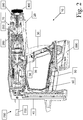
- Fig. 2 shows the driving tool 10 with opened housing 20.
- An actuating device 70 for actuating the driving piston is accommodated in the housing 20.
- the actuating device 70 comprises an electric motor (shown in Fig. 5 ) for converting electrical energy from the electrical battery 590 into rotational energy, a transmission 400 for transferring a torque of the electric motor to a spindle drive 300, a roll train 260 for transmitting a force from the spindle drive 300 to a spring 200 and for transmitting a force from the spring 200 to the driving piston.
- an electric motor shown in Fig. 5
- the actuating device 70 comprises an electric motor (shown in Fig. 5 ) for converting electrical energy from the electrical battery 590 into rotational energy, a transmission 400 for transferring a torque of the electric motor to a spindle drive 300, a roll train 260 for transmitting a force from the spindle drive 300 to a spring 200 and for transmitting a force from the spring 200 to the driving piston.
- Figs. 3 and 4 show the roll train 260 in more detail in an expanded state ( Fig. 3 ) and a tensioned state ( Fig. 4 ), respectively.
- the roll train 260 comprises a belt 270, a front roll holder 281 having front rolls 291, and a rear roll holder 282 having rear rolls 292.
- the roll holders 281, 282 are made from an e.g. fiber-reinforced plastic.
- the roll holders 281, 282 comprise guide rails 285.
- the spindle drive 300 comprises a spindle 310, a spindle nut 320 (not visible in Fig.
- the belt 270 engages with the spindle nut 302 and the driving piston 100, and runs around the rolls 291, 292, thereby forming the roll train 260.
- the driving piston 100 is held in a coupler 150.
- the spring 200 comprises a front spring element 210 having a front spring end 230 and a rear spring element 220 having a rear spring end 240.
- the front spring end 230 is held in the front roll holder 281, whereas the rear spring end 240 is held in the rear roll holder 282.
- the roll train 260 provides for a step-up transmission of a relative speed of the spring ends 230, 240 with respect to one another into a speed of the driving piston 100 by a factor of two.
- the spring elements 210, 220 are supported at their facing sides against the housing by support rings 250. By the symmetric arrangement of the spring elements 210, 220, any recoil forces caused by the spring elements 210, 220 are canceled out, thus improving an operating comfort of the driving tool 10.
- Fig. 3 shows the roll train 260 in an expanded state, in which the spring elements 210, 220 are relaxed.
- Fig. 4 shows the roll train 260 in a tensioned state, in which the spring elements 210, 220 are compressed.
- the spindle nut 320 is now located at a front end of the spindle 310 and pulls the belt 270 into the rear spring element 220. Therefore, the roll holders 281, 282 are moved toward each other, and the spring elements 210, 220 are tensioned.
- the driving piston 100 is held by the coupler 150 against a spring force of the spring elements 210, 220.
- a user pulls the trigger 34 ( Figs. 1 , 2 ), causing the coupler 150 to release the driving piston 100.
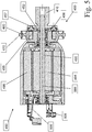
- Fig. 5 shows the electric motor 480 of the actuating device 70 ( Fig. 2 ) having a motor output 490 in a cross-sectional view.
- the electric motor 480 is formed as a brush-less direct-current (BLDC) motor and has magnet coils 495 for driving the motor output 490 that comprises a permanent magnet 491.
- the motor output 490 rotates about a rotational axis 560.
- the electric motor 480 is held by a not-shown motor receptacle and supplied with electrical energy from the electrical battery 590 by means of crimp contacts 506.
- the driving tool 10 comprises a control unit which controls the electric motor 480 by means of a control line 505 in a manner as described below.
- a motor pinion 410 is fastened locked in rotation by a press fit.
- the motor pinion 410 is driven by the motor output 490 and drives the spindle drive 300 by means of the transmission 400 ( Fig. 2 ) and the spindle gear 440 ( Figs. 3, 4 ).
- a retaining mechanism 450 is supported, on one hand, by means of a bearing 452 on the motor output 490 such that it may rotate and, on the other hand, locked in rotation by means of a ring-shaped assembly element 470 on the motor receptacle.
- a ring-shaped motor damping element 460 for damping relative movements between the electric motor 480 and the motor receptacle.
- the retaining mechanism 450 comprises a magnetic coil 455 that may exert a force of attraction on a magnetic armature 456 when energized.
- the magnetic armature 456 extends into an opening 457 formed in the motor pinion 410. Due to the force of attraction, the magnetic armature 456 is pressed against the retaining mechanism 450 such that a rotation of the motor output 490 is braked or prevented when the magnetic coil 455 is energized.
- Fig. 6 shows the electric motor 480 in a schematic view.
- the magnet coils 495 comprise three pairs A, B, C of magnet coils arranged equidistantly along a circumference of the electric motor 480, each pair A, B, C comprising two magnet coils arranged at opposite positions relative to each other with respect to the axis of rotation (which is oriented perpendicular to a plane of projection in Fig. 6 ).
- the magnet coils comprise one, two, four or more pairs of magnet coils arranged equidistantly along a circumference of the electric motor.
- the permanent magnet 491 is positioned on the axis of rotation and has a north pole N and a south pole S which are likewise arranged on opposite sides of the axis of rotation.
- the principle of operation is based on electrical energy conversion into mechanical energy by the magnetic attractive forces between the permanent magnet 491 and a rotating magnetic field induced in the magnet coils 495.
- the magnet coils 495 or pairs of magnet coils are supplied with electric current one after another (commutation).
- the rotating permanent magnet 491 induces a secondary magnetic field in the magnet coils 495 generating a back-electromotive force (BEMF) which reduces an efficiency of the electric motor 480.
- BEMF back-electromotive force
- Fig. 7 shows another three embodiments of a rotor having several permanent magnets.
- Fig. 7a shows a rotor 710 comprising a shaft 711, a hub 712 mounted on the shaft 711 and rotating with the shaft 711, and two pairs of permanent magnets 713 mounted to an outer surface of the hub 712 equidistantly along a circumference of the hub 712 and each having a north pole N and a south pole S.
- Fig. 7a shows a rotor 710 comprising a shaft 711, a hub 712 mounted on the shaft 711 and rotating with the shaft 711, and two pairs of permanent magnets 713 mounted to an outer surface of the hub 712 equidistantly along a circumference of the hub 712 and each having a north pole N and a south pole S.
- Fig. 7a shows a rotor 710 comprising a shaft 711, a hub 712 mounted on the shaft 711 and rotating with the shaft 711, and two pairs of permanent
- FIG. 7b shows a rotor 720 comprising a shaft 721, a hub 722 mounted on the shaft 721 and rotating with the shaft 721, and three pairs of permanent magnets 723 embedded in a bulk material of the hub 722 equidistantly along a circumference of the hub 722 and each having a north pole N and a south pole S.
- Fig. 7c) shows a rotor 730 comprising a shaft 731, a hub 732 mounted on the shaft 731 and rotating with the shaft 731, and four pairs of permanent magnets 733 inserted into respective holders, e.g. bores, provided in the hub 732 equidistantly along a circumference of the hub 732 and each having a north pole N and a south pole S.
- Fig. 8 shows a wiring diagram 800 of an electric motor 801 having a stator 810 and a motor control circuit 820 supplied with electrical energy by an electrical battery 830.
- the electrical battery 830 comprises a high-connection contact 831 and a low-connection contact 832 and provides a battery voltage V BATT between the high-connection contact 831 and the low-connection contact 832, e.g. 12 Volts or 22 Volts or 48 Volts.
- the motor control circuit 820 comprises a high connection line 821 electrically connected to the high-connection contact 831, and a low connection line 822 electrically connected to the low-connection contact 832, such that the battery voltage V BATT is provided between the high connection line and the low connection line.
- the motor control circuit 820 further comprises three high switches A H , B H , C H , three low switches A L , B L , C L , and three intermediate contacts V A , V B , V C .
- Each of the intermediate contacts V A , V B , V C is electrically connected to the high connection line 821 via one of the high switches A H , B H , C H , respectively, and to the low connection line 822 via one of the low switches A L , B L , C L , respectively.
- the high switches A H , B H , C H and the low switches A L , B L , C L are formed as field-effect transistors, e.g. MOSFET's.
- the stator 810 comprises three magnet coils 811, 812, 813.
- a first magnet coil 811 has a first end electrically connected to the intermediate contact V A , and a second end electrically connected to the intermediate contact V B .
- the first magnet coil 811 thus interconnects the intermediate contacts V A and V B to each other.
- a second magnet coil 812 has a first end electrically connected to the intermediate contact V B , and a second end electrically connected to the intermediate contact V C .
- the second magnet coil 812 thus interconnects the intermediate contacts V B and V C to each other.
- a third magnet coil 813 has a first end electrically connected to the intermediate contact V C , and a second end electrically connected to the intermediate contact V A .
- the third magnet coil 813 thus interconnects the intermediate contacts Vc and V A to each other.
- Each of the magnet coils 811, 812, 813 has an intrinsic inductance L AB , L BC , L CA , respectively, a resistance R AB , R BC , R CA , respectively, and a back-electromotive force represented as an alternating voltage source e AB , e BC , e CA , respectively.
- the high switches A H , B H , C H , and the low switches A L , B L , C L are actuated according to a commutation scheme as described below with reference to Fig. 9 .
- Fig. 9 shows a commutation table 900 of a method of controlling the electric motor 820.
- the high switch A H and the low switches B L and C L are closed, or switched to "on" ("1"), thereby electrically connecting the intermediate contact V A to the high connection line 821, and the intermediate contacts V B and V C to the low connection line 822, respectively.
- the remaining high and low switches, i.e. A L , B H and C H are open, or switched to "off” ("0").
- the first magnet coil 811 is energized to accelerate the permanent magnet and hence drives rotation of the rotor 810.
- the second magnet coil 812 is short-circuited which prevents the magnetic field from inducing in the second magnet coil 812 a secondary electric current possibly detrimental to the above acceleration of the permanent magnet.
- first commutation phase 1 the low switch B L is switched to "off” ("0"), thereby electrically disconnecting the intermediate contact V B from the low connection line 822, and high switch B H is switched to "on” ("1"), thereby electrically connecting the intermediate contact V B to the high connection line 821.
- the remaining high and low switches i.e. A H , A L , C H and C L , remain open or closed, respectively.
- the third magnet coil 813 is energized to accelerate the permanent magnet and, at the same time, the first magnet coil 811 is short-circuited immediately following the first commutation phase 1.
- a dead-time interval is provided to elapse after the low switch B L is switched to "off” ("0") and before the high switch B H is switched to "on” ("1"). During the dead-time interval, none of the switches B L , B H is closed.
- the dead-time interval is provided by a software-implemented or hardware-implemented dead-time interval.
- a mechanical power and/or torque that the electric motor 801 generates depends on the product between the phase currents and the back-electromotive force (BEMF) generated.
- BEMF back-electromotive force
- the way in which the values of those two functions interact determines the magnitude of the generated energy. For instance, matching phase current and BEMF maximum values would create a high-power peak and contribute to the average mechanical power. Having high ripple in the power is not convenient because the torque also would oscillate, therefore, one must avoid having high currents when the BEMF is low (and vice versa), that is, making the two signals coincide as much as possible.
- Another aspect is avoiding non-coincident polarities of the two signals, because that would result in negative power, that is, in a torque that opposes to the motor sense of rotation, instead of pushing it forward.
- the method described above offers a speed, torque and efficiency increase.
- the torque characteristic is more uniform and therefore the energy transfer to the rotor results in a smoother rotation of the motor.
Landscapes
- Engineering & Computer Science (AREA)
- Power Engineering (AREA)
- Mechanical Engineering (AREA)
- Physics & Mathematics (AREA)
- Fluid Mechanics (AREA)
- Control Of Motors That Do Not Use Commutators (AREA)
Abstract
A method of controlling a BLDC electric motor having a stator and a rotor, the stator having a plurality of magnet coils, the rotor having a permanent magnet driven by the plurality of magnet coils, comprisinga) supplying a voltage to a first of the plurality of magnet coils,b) short-circuiting a second of the plurality of magnet coils during step a).
Description
- The invention relates to a method of controlling a motor, such as a brush-less direct current (BLDC) electric motor. More particularly, the invention relates to a method of controlling a BLDC electric motor having a stator and a rotor, the stator having a plurality of magnet coils, and the rotor having a permanent magnet driven by the plurality of magnet coils. One constraint with the use of a BLDC electric motor, as with any electric motor, is the motor's efficiency in transferring electric energy into rotational energy. Another constraint with the use of a BLDC electric motor, as with any electric motor, is the performance of the motor with regard to a rotational speed, torque and so on, at a given voltage and/or electric current supplied to the motor.
- The above constraints are addressed by a method of controlling a BLDC electric motor having a stator and a rotor, the stator having a plurality of magnet coils, the rotor having a permanent magnet driven by the plurality of magnet coils, comprising a) supplying a voltage to a first of the plurality of magnet coils, and b) short-circuiting a second of the plurality of magnet coils during step a). Supplying the voltage to the first magnet coil creates an electric current flowing through the first magnet coil which in turn creates a magnetic field in an area inside and outside the first magnetic coil. Such a magnetic field accelerates the permanent magnet and hence drives rotation of the BLDC motor. Short-circuiting the second magnet coil during step a) prevents the magnetic field from inducing in the second magnet coil a secondary electric current possibly detrimental to the above acceleration of the permanent magnet.
- In a preferred embodiment, the method further comprises short-circuiting the first of the plurality of magnet coils following step a) or, in particular immediately following step a).
- The above constraints are further addressed by a method of controlling a BLDC electric motor having a stator and a rotor, the stator having a plurality of magnet coils, the rotor having a permanent magnet driven by the plurality of magnet coils, wherein the electric motor comprises a motor control circuit having a high connection line, a low connection line, a plurality of high switches, a plurality of low switches, a plurality of intermediate contacts connected to the high connection line via one of the plurality of high switches and connected to the low connection line via one of the plurality of low switches, wherein each one of the plurality of magnet coils has a first end electrically connected to a first one of the plurality of intermediate contacts and a second end electrically connected to a second one of the plurality of intermediate contacts, the each one of the plurality of magnet coils thereby electrically interconnecting the first one of the plurality of intermediate contacts and the second one of the plurality of intermediate contacts, comprising
providing a voltage between the high connection line and the low connection line
closing a first one of the plurality of high switches, thereby electrically connecting the first one of the plurality of intermediate contacts to the high connection line during a first commutation phase,
closing a second one of the plurality of low switches, thereby electrically connecting the second one of the plurality of intermediate contacts to the low connection line during the first commutation phase,
closing a third one of the plurality of low switches, thereby electrically connecting a third one of the plurality of intermediate contacts to the low connection line during the first commutation phase. - In a preferred embodiment, the method further comprises
opening the second one of the plurality of low switches, thereby electrically disconnecting the second one of the plurality of intermediate contacts from the low connection line during a second commutation phase following the first commutation phase, and
closing a second one of the plurality of high switches, thereby electrically connecting the second one of the plurality of intermediate contacts to the high connection line during the second commutation phase. - In a preferred embodiment, the second commutation phase is immediately following the first commutation phase, with no other commutation phases thereinbetween. In another preferred embodiment, a dead-time interval is elapsing after the second one of the plurality of low switches is opened and before the second one of the plurality of high switches is closed.
- In another preferred embodiment, the plurality of magnet coils consists of three magnet coils. In another preferred embodiment, the plurality of high switches consists of three high switches. In another preferred embodiment, the plurality of low switches consists of three low switches. In another preferred embodiment, the plurality of intermediate contacts consists of three intermediate contacts. In another preferred embodiment, each of the plurality of high switches and/or each of the plurality of low switches comprises a field-effect transistor.
- In another preferred embodiment, the method is integrated in a method of operating a driving tool having a driving piston and an actuating device for actuating the driving piston such that the driving piston drives a fastening element into a substrate, wherein the actuating device comprises a BLDC motor controlled as in any of the embodiments above.
- Further aspects and advantages of the fastening tool, associated parts and a method of use thereofwill become apparent from the ensuing description that is given by way of example only and with reference to the accompanying drawings in which:
- Fig. 1
- illustrates a side view of a driving device,
- Fig. 2
- illustrates a side view of the driving device with opened housing,
- Fig. 3
- illustrates a perspective view of a tensioning device,
- Fig. 4
- illustrates a perspective view of the tensioning device in a tensioned state,
- Fig. 5
- illustrates a cross-sectional view of an electric motor,
- Fig. 6
- illustrates a schematic view of the electric motor,
- Fig. 7
- illustrates several arrangements of permanent magnets within an electric motor,
- Fig. 8
- illustrates a wiring diagram of an electric motor, and
- Fig. 9
- illustrates a commutation table of a method of controlling an electric motor.
-
Figs. 1 shows adriving tool 10 for driving a fastening element, e.g. a nail or bolt, into a substrate in a side view. Thedriving tool 10 has a driving piston (shown inFigs. 3 and 4 ) for driving a fastening element into a substrate, and ahousing 20 accommodating the driving piston and an actuating device for actuating the driving piston. Thedriving tool 10 has agrip 30, amagazine 40 and abridge 50 connecting thegrip 30 to themagazine 40. Ascaffold hook 60 for hanging thedriving tool 10 on a scaffold or the like and anelectrical battery 590 are fastened to thebridge 50. Atrigger 34 and ahand switch 35 are arranged on thegrip 30. Thedriving tool 10 further has aguide channel 700 for guiding the fastening element and a press-onprobe 750 for detecting a pressing thedriving tool 10 on the substrate. An alignment of thedriving tool 10 perpendicular to a surface of the substrate is supported by asupport element 45. -
Fig. 2 shows thedriving tool 10 with openedhousing 20. An actuatingdevice 70 for actuating the driving piston is accommodated in thehousing 20. The actuatingdevice 70 comprises an electric motor (shown inFig. 5 ) for converting electrical energy from theelectrical battery 590 into rotational energy, atransmission 400 for transferring a torque of the electric motor to aspindle drive 300, aroll train 260 for transmitting a force from thespindle drive 300 to aspring 200 and for transmitting a force from thespring 200 to the driving piston. -
Figs. 3 and 4 show theroll train 260 in more detail in an expanded state (Fig. 3 ) and a tensioned state (Fig. 4 ), respectively. Theroll train 260 comprises abelt 270, afront roll holder 281 havingfront rolls 291, and arear roll holder 282 havingrear rolls 292. Theroll holders roll holders Figs. 1 and2 ), theroll holders guide rails 285. Thespindle drive 300 comprises aspindle 310, a spindle nut 320 (not visible inFig. 3 ) and aspindle gear 440. Thebelt 270 engages with the spindle nut 302 and thedriving piston 100, and runs around therolls roll train 260. Thedriving piston 100 is held in acoupler 150. - The
spring 200 comprises afront spring element 210 having afront spring end 230 and arear spring element 220 having arear spring end 240. Thefront spring end 230 is held in thefront roll holder 281, whereas therear spring end 240 is held in therear roll holder 282. Theroll train 260 provides for a step-up transmission of a relative speed of the spring ends 230, 240 with respect to one another into a speed of thedriving piston 100 by a factor of two. Thespring elements spring elements spring elements tool 10. - As mentioned above,
Fig. 3 shows theroll train 260 in an expanded state, in which thespring elements Fig. 4 shows theroll train 260 in a tensioned state, in which thespring elements spindle nut 320 is now located at a front end of thespindle 310 and pulls thebelt 270 into therear spring element 220. Therefore, theroll holders spring elements driving piston 100 is held by thecoupler 150 against a spring force of thespring elements piston 100 to drive a fastening element into a substrate, a user pulls the trigger 34 (Figs. 1 ,2 ), causing thecoupler 150 to release thedriving piston 100. -
Fig. 5 shows theelectric motor 480 of the actuating device 70 (Fig. 2 ) having amotor output 490 in a cross-sectional view. Theelectric motor 480 is formed as a brush-less direct-current (BLDC) motor and has magnet coils 495 for driving themotor output 490 that comprises apermanent magnet 491. Themotor output 490 rotates about arotational axis 560. Theelectric motor 480 is held by a not-shown motor receptacle and supplied with electrical energy from theelectrical battery 590 by means ofcrimp contacts 506. The drivingtool 10 comprises a control unit which controls theelectric motor 480 by means of acontrol line 505 in a manner as described below. - On the
motor output 490, amotor pinion 410 is fastened locked in rotation by a press fit. Themotor pinion 410 is driven by themotor output 490 and drives thespindle drive 300 by means of the transmission 400 (Fig. 2 ) and the spindle gear 440 (Figs. 3, 4 ). Aretaining mechanism 450 is supported, on one hand, by means of abearing 452 on themotor output 490 such that it may rotate and, on the other hand, locked in rotation by means of a ring-shapedassembly element 470 on the motor receptacle. A ring-shapedmotor damping element 460 for damping relative movements between theelectric motor 480 and the motor receptacle. Theretaining mechanism 450 comprises amagnetic coil 455 that may exert a force of attraction on amagnetic armature 456 when energized. Themagnetic armature 456 extends into anopening 457 formed in themotor pinion 410. Due to the force of attraction, themagnetic armature 456 is pressed against theretaining mechanism 450 such that a rotation of themotor output 490 is braked or prevented when themagnetic coil 455 is energized. -
Fig. 6 shows theelectric motor 480 in a schematic view. The magnet coils 495 comprise three pairs A, B, C of magnet coils arranged equidistantly along a circumference of theelectric motor 480, each pair A, B, C comprising two magnet coils arranged at opposite positions relative to each other with respect to the axis of rotation (which is oriented perpendicular to a plane of projection inFig. 6 ). In not-shown embodiments, the magnet coils comprise one, two, four or more pairs of magnet coils arranged equidistantly along a circumference of the electric motor. Thepermanent magnet 491 is positioned on the axis of rotation and has a north pole N and a south pole S which are likewise arranged on opposite sides of the axis of rotation. - The principle of operation is based on electrical energy conversion into mechanical energy by the magnetic attractive forces between the
permanent magnet 491 and a rotating magnetic field induced in the magnet coils 495. In order to rotate the magnetic field, the magnet coils 495 or pairs of magnet coils are supplied with electric current one after another (commutation). However, the rotatingpermanent magnet 491 induces a secondary magnetic field in the magnet coils 495 generating a back-electromotive force (BEMF) which reduces an efficiency of theelectric motor 480. It is an object of the invention to increase the motor's efficiency which may be solved by reducing the back-electromotive forces. -
Fig. 7 shows another three embodiments of a rotor having several permanent magnets.Fig. 7a) shows arotor 710 comprising ashaft 711, ahub 712 mounted on theshaft 711 and rotating with theshaft 711, and two pairs ofpermanent magnets 713 mounted to an outer surface of thehub 712 equidistantly along a circumference of thehub 712 and each having a north pole N and a south pole S.Fig. 7b) shows arotor 720 comprising ashaft 721, ahub 722 mounted on theshaft 721 and rotating with theshaft 721, and three pairs ofpermanent magnets 723 embedded in a bulk material of thehub 722 equidistantly along a circumference of thehub 722 and each having a north pole N and a south pole S.Fig. 7c) shows arotor 730 comprising ashaft 731, ahub 732 mounted on theshaft 731 and rotating with theshaft 731, and four pairs ofpermanent magnets 733 inserted into respective holders, e.g. bores, provided in thehub 732 equidistantly along a circumference of thehub 732 and each having a north pole N and a south pole S. -
Fig. 8 shows a wiring diagram 800 of anelectric motor 801 having astator 810 and amotor control circuit 820 supplied with electrical energy by anelectrical battery 830. Theelectrical battery 830 comprises a high-connection contact 831 and a low-connection contact 832 and provides a battery voltage VBATT between the high-connection contact 831 and the low-connection contact 832, e.g. 12 Volts or 22 Volts or 48 Volts. Themotor control circuit 820 comprises ahigh connection line 821 electrically connected to the high-connection contact 831, and alow connection line 822 electrically connected to the low-connection contact 832, such that the battery voltage VBATT is provided between the high connection line and the low connection line. Themotor control circuit 820 further comprises three high switches AH, BH, CH, three low switches AL, BL, CL, and three intermediate contacts VA, VB, VC. Each of the intermediate contacts VA, VB, VC is electrically connected to thehigh connection line 821 via one of the high switches AH, BH, CH, respectively, and to thelow connection line 822 via one of the low switches AL, BL, CL, respectively. The high switches AH, BH, CH and the low switches AL, BL, CL are formed as field-effect transistors, e.g. MOSFET's. - The
stator 810 comprises threemagnet coils first magnet coil 811 has a first end electrically connected to the intermediate contact VA, and a second end electrically connected to the intermediate contact VB. Thefirst magnet coil 811 thus interconnects the intermediate contacts VA and VB to each other. Asecond magnet coil 812 has a first end electrically connected to the intermediate contact VB, and a second end electrically connected to the intermediate contact VC. Thesecond magnet coil 812 thus interconnects the intermediate contacts VB and VC to each other. Athird magnet coil 813 has a first end electrically connected to the intermediate contact VC, and a second end electrically connected to the intermediate contact VA. Thethird magnet coil 813 thus interconnects the intermediate contacts Vc and VA to each other. Each of the magnet coils 811, 812, 813 has an intrinsic inductance LAB, LBC, LCA, respectively, a resistance RAB, RBC, RCA, respectively, and a back-electromotive force represented as an alternating voltage source eAB, eBC, eCA, respectively. - In order to control the
electric motor 801, the high switches AH, BH, CH, and the low switches AL, BL, CL are actuated according to a commutation scheme as described below with reference toFig. 9 . -
Fig. 9 shows a commutation table 900 of a method of controlling theelectric motor 820. During afirst commutation phase 1, the high switch AH and the low switches BL and CL are closed, or switched to "on" ("1"), thereby electrically connecting the intermediate contact VA to thehigh connection line 821, and the intermediate contacts VB and VC to thelow connection line 822, respectively. The remaining high and low switches, i.e. AL, BH and CH, are open, or switched to "off" ("0"). Accordingly, thefirst magnet coil 811 is energized to accelerate the permanent magnet and hence drives rotation of therotor 810. At the same time, thesecond magnet coil 812 is short-circuited which prevents the magnetic field from inducing in the second magnet coil 812 a secondary electric current possibly detrimental to the above acceleration of the permanent magnet. - At the end of
first commutation phase 1, the low switch BL is switched to "off" ("0"), thereby electrically disconnecting the intermediate contact VB from thelow connection line 822, and high switch BH is switched to "on" ("1"), thereby electrically connecting the intermediate contact VB to thehigh connection line 821. The remaining high and low switches, i.e. AH, AL, CH and CL, remain open or closed, respectively. Accordingly, in asecond commutation phase 2 immediately following thefirst commutation phase 1, thethird magnet coil 813 is energized to accelerate the permanent magnet and, at the same time, thefirst magnet coil 811 is short-circuited immediately following thefirst commutation phase 1. In order to prevent short-circuiting thehigh connection line 821 with thelow connection line 822 during switching from thefirst commutation phase 1 to thesecond commutation phase 2 via the intermediate contact VB, a dead-time interval is provided to elapse after the low switch BL is switched to "off" ("0") and before the high switch BH is switched to "on" ("1"). During the dead-time interval, none of the switches BL, BH is closed. The dead-time interval is provided by a software-implemented or hardware-implemented dead-time interval. - A mechanical power and/or torque that the
electric motor 801 generates depends on the product between the phase currents and the back-electromotive force (BEMF) generated. The way in which the values of those two functions interact determines the magnitude of the generated energy. For instance, matching phase current and BEMF maximum values would create a high-power peak and contribute to the average mechanical power. Having high ripple in the power is not convenient because the torque also would oscillate, therefore, one must avoid having high currents when the BEMF is low (and vice versa), that is, making the two signals coincide as much as possible. Another aspect is avoiding non-coincident polarities of the two signals, because that would result in negative power, that is, in a torque that opposes to the motor sense of rotation, instead of pushing it forward. - The method described above offers a speed, torque and efficiency increase. On the other hand, the torque characteristic is more uniform and therefore the energy transfer to the rotor results in a smoother rotation of the motor.
- The foregoing description of exemplary embodiments of the invention have been presented for purposes of illustration and of description. It is not intended to be exhaustive or to limit the invention to the precise form disclosed, and modifications and variations are possible in light of the above teachings or may be acquired from practice of the invention. The functionality described may be distributed among modules that differ in number and distribution of functionality from those described herein. Additionally, the order of execution of the functions may be changed depending on the embodiment. The embodiments were chosen and described in order to explain the principles of the invention and as practical applications of the invention to enable one skilled in the art to utilize the invention in various embodiments and with various modifications as suited to the particular use contemplated. It is intended that the scope of the invention be defined by the claims appended hereto and their equivalents.
Claims (14)
- A method of controlling a BLDC electric motor having a stator and a rotor, the stator having a plurality of magnet coils, the rotor having a permanent magnet driven by the plurality of magnet coils, comprisinga) supplying a voltage to a first of the plurality of magnet coils, andb) short-circuiting a second of the plurality of magnet coils during step a).
- A method according to claim 1, comprising short-circuiting the first of the plurality of magnet coils following step a).
- A method according to claim 2, comprising short-circuiting the first of the plurality of magnet coils immediately following step a).
- A method of controlling a BLDC electric motor having a stator and a rotor, the stator having a plurality of magnet coils, the rotor having a permanent magnet driven by the plurality of magnet coils, wherein the electric motor comprises a motor control circuit having a high connection line, a low connection line, a plurality of high switches, a plurality of low switches, and a plurality of intermediate contacts each one connected to the high connection line via one of the plurality of high switches and connected to the low connection line via one of the plurality of low switches, wherein each one of the plurality of magnet coils has a first end electrically connected to a first one of the plurality of intermediate contacts and a second end electrically connected to a second one of the plurality of intermediate contacts, the each one of the plurality of magnet coils thereby electrically interconnecting the first one of the plurality of intermediate contacts and the second one of the plurality of intermediate contacts, comprising- providing a voltage between the high connection line and the low connection line- closing a first one of the plurality of high switches, thereby electrically connecting the first one of the plurality of intermediate contacts to the high connection line during a first commutation phase,- closing a second one of the plurality of low switches, thereby electrically connecting the second one of the plurality of intermediate contacts to the low connection line during the first commutation phase, and- closing a third one of the plurality of low switches, thereby electrically connecting a third one of the plurality of intermediate contacts to the low connection line during the first commutation phase.
- A method according to claim 4, further comprising- opening the second one of the plurality of low switches, thereby electrically disconnecting the second one of the plurality of intermediate contacts from the low connection line during a second commutation phase following the first commutation phase, and- closing a second one of the plurality of high switches, thereby electrically connecting the second one of the plurality of intermediate contacts to the high connection line during the second commutation phase.
- A method according to claim 5, wherein the second commutation phase is immediately following the first commutation phase.
- A method according to any of claims 5 and 6, wherein a dead-time interval is elapsing after the second one of the plurality of low switches is opened and before the second one of the plurality of high switches is closed.
- A method according to any of the preceding claims, wherein the plurality of magnet coils consists of three magnet coils.
- A method according to any of the preceding claims, wherein the plurality of high switches consists of three high switches.
- A method according to any of the preceding claims, wherein the plurality of low switches consists of three low switches.
- A method according to any of the preceding claims, wherein the plurality of intermediate contacts consists of three intermediate contacts.
- A method according to any of the preceding claims, wherein each of the plurality of high switches comprises a field-effect transistor.
- A method according to any of the preceding claims, wherein each of the plurality of low switches comprises a field-effect transistor.
- A method of operating a driving tool having a driving piston and an actuating device for actuating the driving piston such that the driving piston drives a fastening element into a substrate, the actuating device comprising a BLDC motor, the method comprising a method of controlling the BLDC motor according to any of the preceding claims.
Priority Applications (6)
| Application Number | Priority Date | Filing Date | Title |
|---|---|---|---|
| EP18213489.0A EP3672064A1 (en) | 2018-12-18 | 2018-12-18 | Motor control method |
| PCT/EP2019/083013 WO2020126405A1 (en) | 2018-12-18 | 2019-11-29 | Motor control method |
| JP2021534125A JP2022518114A (en) | 2018-12-18 | 2019-11-29 | Motor control method |
| EP19808837.9A EP3900177A1 (en) | 2018-12-18 | 2019-11-29 | Motor control method |
| US17/415,195 US20220069747A1 (en) | 2018-12-18 | 2019-11-29 | Motor control method |
| CN201980084268.9A CN113261198A (en) | 2018-12-18 | 2019-11-29 | motor control method |
Applications Claiming Priority (1)
| Application Number | Priority Date | Filing Date | Title |
|---|---|---|---|
| EP18213489.0A EP3672064A1 (en) | 2018-12-18 | 2018-12-18 | Motor control method |
Publications (1)
| Publication Number | Publication Date |
|---|---|
| EP3672064A1 true EP3672064A1 (en) | 2020-06-24 |
Family
ID=64744668
Family Applications (2)
| Application Number | Title | Priority Date | Filing Date |
|---|---|---|---|
| EP18213489.0A Withdrawn EP3672064A1 (en) | 2018-12-18 | 2018-12-18 | Motor control method |
| EP19808837.9A Withdrawn EP3900177A1 (en) | 2018-12-18 | 2019-11-29 | Motor control method |
Family Applications After (1)
| Application Number | Title | Priority Date | Filing Date |
|---|---|---|---|
| EP19808837.9A Withdrawn EP3900177A1 (en) | 2018-12-18 | 2019-11-29 | Motor control method |
Country Status (5)
| Country | Link |
|---|---|
| US (1) | US20220069747A1 (en) |
| EP (2) | EP3672064A1 (en) |
| JP (1) | JP2022518114A (en) |
| CN (1) | CN113261198A (en) |
| WO (1) | WO2020126405A1 (en) |
Families Citing this family (1)
| Publication number | Priority date | Publication date | Assignee | Title |
|---|---|---|---|---|
| EP4627702A4 (en) * | 2022-12-16 | 2026-02-25 | Peter Grandics | PERMANENT MAGNET MOTOR |
Citations (4)
| Publication number | Priority date | Publication date | Assignee | Title |
|---|---|---|---|---|
| EP1081827A1 (en) * | 1999-09-01 | 2001-03-07 | Ramachandran Ramarathnam | A portable electric tool |
| US20090065226A1 (en) * | 2007-09-12 | 2009-03-12 | Hilti Aktiengesellschaft | Hand-held power tool with air spring percussion mechanism, linear motor, and control process |
| US20150091480A1 (en) * | 2013-09-28 | 2015-04-02 | Andreas Stihl Ag & Co. Kg | Method for braking an electric drive motor |
| US20180013360A1 (en) * | 2016-07-06 | 2018-01-11 | Black & Decker Inc. | Electronic braking of brushless dc motor in a power tool |
Family Cites Families (3)
| Publication number | Priority date | Publication date | Assignee | Title |
|---|---|---|---|---|
| JP2015223680A (en) * | 2014-05-29 | 2015-12-14 | 株式会社マキタ | Hammering tool |
| US10411620B2 (en) * | 2015-07-31 | 2019-09-10 | Koki Holdings Co., Ltd. | Power tool |
| JP6703339B2 (en) * | 2017-05-11 | 2020-06-03 | 三菱電機株式会社 | Electric power steering device |
-
2018
- 2018-12-18 EP EP18213489.0A patent/EP3672064A1/en not_active Withdrawn
-
2019
- 2019-11-29 WO PCT/EP2019/083013 patent/WO2020126405A1/en not_active Ceased
- 2019-11-29 CN CN201980084268.9A patent/CN113261198A/en active Pending
- 2019-11-29 US US17/415,195 patent/US20220069747A1/en not_active Abandoned
- 2019-11-29 EP EP19808837.9A patent/EP3900177A1/en not_active Withdrawn
- 2019-11-29 JP JP2021534125A patent/JP2022518114A/en active Pending
Patent Citations (4)
| Publication number | Priority date | Publication date | Assignee | Title |
|---|---|---|---|---|
| EP1081827A1 (en) * | 1999-09-01 | 2001-03-07 | Ramachandran Ramarathnam | A portable electric tool |
| US20090065226A1 (en) * | 2007-09-12 | 2009-03-12 | Hilti Aktiengesellschaft | Hand-held power tool with air spring percussion mechanism, linear motor, and control process |
| US20150091480A1 (en) * | 2013-09-28 | 2015-04-02 | Andreas Stihl Ag & Co. Kg | Method for braking an electric drive motor |
| US20180013360A1 (en) * | 2016-07-06 | 2018-01-11 | Black & Decker Inc. | Electronic braking of brushless dc motor in a power tool |
Also Published As
| Publication number | Publication date |
|---|---|
| JP2022518114A (en) | 2022-03-14 |
| EP3900177A1 (en) | 2021-10-27 |
| US20220069747A1 (en) | 2022-03-03 |
| CN113261198A (en) | 2021-08-13 |
| WO2020126405A1 (en) | 2020-06-25 |
Similar Documents
| Publication | Publication Date | Title |
|---|---|---|
| US4462467A (en) | Percussion drill machine | |
| US20090001834A1 (en) | Permanent magnet motor | |
| EP2674256B1 (en) | Brushless motor commutation control in a power tool | |
| AU2007276902B2 (en) | Electric motor | |
| AU2018100867A4 (en) | Energy recycle on power tools | |
| WO2013081191A2 (en) | Electric tool | |
| CN204658375U (en) | Power tool | |
| KR20070082819A (en) | Super Efficiency Motor Generator | |
| US20220069747A1 (en) | Motor control method | |
| US20100052451A1 (en) | Constant-power brushless dc motor and the generator thereby | |
| KR20170024744A (en) | The high efficiency direct current motor and thereof control method | |
| US6987375B2 (en) | Dual-stage drive for switched reluctance electric machines | |
| DE69727553D1 (en) | HIGH PERFORMANCE ELECTRIC MOTOR OF THE ELECTRONIC COMMUTATION TYPE | |
| US20110227438A1 (en) | Self Generating Motor-Generator Assembly | |
| EP1479936B1 (en) | Controller of electromagnetic clutch | |
| EP1381149B9 (en) | Starting of switched reluctance generators | |
| KR100753613B1 (en) | Accelerating Apparatus | |
| WO2007032610A1 (en) | Dual machine, and method of power generation and electromotive operation using the same | |
| US20130187580A1 (en) | Controller For Back EMF Reducing Motor | |
| CN111555578A (en) | Full-phase double-drive brushless DC motor | |
| US20240413684A1 (en) | Brushless Electric Machine and Method of Manufacturing a Brushless Electric Machine | |
| AU2021281698B2 (en) | Systems catching residual energy from an electric coil | |
| EP0635927A3 (en) | DC motor with permanent magnet. | |
| KR100817294B1 (en) | Small motor | |
| WO2018020245A1 (en) | An electric machine |
Legal Events
| Date | Code | Title | Description |
|---|---|---|---|
| STAA | Information on the status of an ep patent application or granted ep patent |
Free format text: STATUS: UNKNOWN |
|
| PUAI | Public reference made under article 153(3) epc to a published international application that has entered the european phase |
Free format text: ORIGINAL CODE: 0009012 |
|
| STAA | Information on the status of an ep patent application or granted ep patent |
Free format text: STATUS: THE APPLICATION HAS BEEN PUBLISHED |
|
| AK | Designated contracting states |
Kind code of ref document: A1 Designated state(s): AL AT BE BG CH CY CZ DE DK EE ES FI FR GB GR HR HU IE IS IT LI LT LU LV MC MK MT NL NO PL PT RO RS SE SI SK SM TR |
|
| AX | Request for extension of the european patent |
Extension state: BA ME |
|
| STAA | Information on the status of an ep patent application or granted ep patent |
Free format text: STATUS: THE APPLICATION IS DEEMED TO BE WITHDRAWN |
|
| 18D | Application deemed to be withdrawn |
Effective date: 20210112 |