EP3671963B1 - Connection assembly comprising a withdrawable connector and a fixing foot configured to cooperate with the withdrawable connector - Google Patents
Connection assembly comprising a withdrawable connector and a fixing foot configured to cooperate with the withdrawable connector Download PDFInfo
- Publication number
- EP3671963B1 EP3671963B1 EP18306746.1A EP18306746A EP3671963B1 EP 3671963 B1 EP3671963 B1 EP 3671963B1 EP 18306746 A EP18306746 A EP 18306746A EP 3671963 B1 EP3671963 B1 EP 3671963B1
- Authority
- EP
- European Patent Office
- Prior art keywords
- connector
- extension direction
- withdrawable
- foot
- cooperate
- Prior art date
- Legal status (The legal status is an assumption and is not a legal conclusion. Google has not performed a legal analysis and makes no representation as to the accuracy of the status listed.)
- Active
Links
Images
Classifications
-
- H—ELECTRICITY
- H01—ELECTRIC ELEMENTS
- H01R—ELECTRICALLY-CONDUCTIVE CONNECTIONS; STRUCTURAL ASSOCIATIONS OF A PLURALITY OF MUTUALLY-INSULATED ELECTRICAL CONNECTING ELEMENTS; COUPLING DEVICES; CURRENT COLLECTORS
- H01R9/00—Structural associations of a plurality of mutually-insulated electrical connecting elements, e.g. terminal strips or terminal blocks; Terminals or binding posts mounted upon a base or in a case; Bases therefor
- H01R9/22—Bases, e.g. strip, block, panel
- H01R9/24—Terminal blocks
- H01R9/26—Clip-on terminal blocks for side-by-side rail- or strip-mounting
-
- H—ELECTRICITY
- H01—ELECTRIC ELEMENTS
- H01R—ELECTRICALLY-CONDUCTIVE CONNECTIONS; STRUCTURAL ASSOCIATIONS OF A PLURALITY OF MUTUALLY-INSULATED ELECTRICAL CONNECTING ELEMENTS; COUPLING DEVICES; CURRENT COLLECTORS
- H01R13/00—Details of coupling devices of the kinds covered by groups H01R12/70 or H01R24/00 - H01R33/00
- H01R13/62—Means for facilitating engagement or disengagement of coupling parts or for holding them in engagement
- H01R13/627—Snap or like fastening
-
- H—ELECTRICITY
- H01—ELECTRIC ELEMENTS
- H01R—ELECTRICALLY-CONDUCTIVE CONNECTIONS; STRUCTURAL ASSOCIATIONS OF A PLURALITY OF MUTUALLY-INSULATED ELECTRICAL CONNECTING ELEMENTS; COUPLING DEVICES; CURRENT COLLECTORS
- H01R13/00—Details of coupling devices of the kinds covered by groups H01R12/70 or H01R24/00 - H01R33/00
- H01R13/62—Means for facilitating engagement or disengagement of coupling parts or for holding them in engagement
- H01R13/627—Snap or like fastening
- H01R13/6275—Latching arms not integral with the housing
-
- H—ELECTRICITY
- H01—ELECTRIC ELEMENTS
- H01R—ELECTRICALLY-CONDUCTIVE CONNECTIONS; STRUCTURAL ASSOCIATIONS OF A PLURALITY OF MUTUALLY-INSULATED ELECTRICAL CONNECTING ELEMENTS; COUPLING DEVICES; CURRENT COLLECTORS
- H01R13/00—Details of coupling devices of the kinds covered by groups H01R12/70 or H01R24/00 - H01R33/00
- H01R13/62—Means for facilitating engagement or disengagement of coupling parts or for holding them in engagement
- H01R13/629—Additional means for facilitating engagement or disengagement of coupling parts, e.g. aligning or guiding means, levers, gas pressure electrical locking indicators, manufacturing tolerances
-
- H—ELECTRICITY
- H01—ELECTRIC ELEMENTS
- H01R—ELECTRICALLY-CONDUCTIVE CONNECTIONS; STRUCTURAL ASSOCIATIONS OF A PLURALITY OF MUTUALLY-INSULATED ELECTRICAL CONNECTING ELEMENTS; COUPLING DEVICES; CURRENT COLLECTORS
- H01R24/00—Two-part coupling devices, or either of their cooperating parts, characterised by their overall structure
-
- H—ELECTRICITY
- H01—ELECTRIC ELEMENTS
- H01R—ELECTRICALLY-CONDUCTIVE CONNECTIONS; STRUCTURAL ASSOCIATIONS OF A PLURALITY OF MUTUALLY-INSULATED ELECTRICAL CONNECTING ELEMENTS; COUPLING DEVICES; CURRENT COLLECTORS
- H01R13/00—Details of coupling devices of the kinds covered by groups H01R12/70 or H01R24/00 - H01R33/00
- H01R13/62—Means for facilitating engagement or disengagement of coupling parts or for holding them in engagement
- H01R13/627—Snap or like fastening
- H01R13/6271—Latching means integral with the housing
- H01R13/6272—Latching means integral with the housing comprising a single latching arm
-
- H—ELECTRICITY
- H01—ELECTRIC ELEMENTS
- H01R—ELECTRICALLY-CONDUCTIVE CONNECTIONS; STRUCTURAL ASSOCIATIONS OF A PLURALITY OF MUTUALLY-INSULATED ELECTRICAL CONNECTING ELEMENTS; COUPLING DEVICES; CURRENT COLLECTORS
- H01R9/00—Structural associations of a plurality of mutually-insulated electrical connecting elements, e.g. terminal strips or terminal blocks; Terminals or binding posts mounted upon a base or in a case; Bases therefor
- H01R9/22—Bases, e.g. strip, block, panel
- H01R9/24—Terminal blocks
- H01R9/2408—Modular blocks
Definitions
- the invention relates of a connection assembly comprising a withdrawable connector and a fixing foot configured to cooperate with the withdrawable connector.
- connection assembly In the field of connection assembly, it is known to use a system for fastening together two constituent elements of an electrical connection assembly.
- Patent application US 6,626,709 has thus proposed an electrical assembly of the tenon and mortise type, which comprise male fastener which comprises one tenon having a longitudinal axis and provided with a free end called an engagement end, and a locking rib located at a distance from the tenon, away from the engagement end and oriented transversely to the longitudinal axis, that projects from a fastening face.
- the electrical assembly also comprises a female fastener complementary to the male fastener.
- US4425018 describes a connection assembly comprising a withdrawable connector and a fixing foot
- the withdrawable connector comprises: an insulating body having a connector cooperation area configured to cooperate, in a mounting position, with a fixing foot configured to be fixed to a support, said insulating body extending in a first extension direction from the connector cooperation area, a conductive bar disposed in the insulating body, a connection socket arranged to cooperate with an external socket, said connection socket being configured to electrically connect the external socket to the conductive bar when the external socket cooperates with the connection socket, and wherein the connection socket is arranged for the external socket to cooperate with said connection socket by a relative movement in an insertion direction transverse to the first extension direction
- the fixing foot comprises: a fixing portion configured to be fixed to a support; and a body having a foot cooperation area configured to cooperate with a withdrawable connector, said body extending in a second extension direction from the fixing portion.
- the present invention aims to solve all or some of the disadvantages mentioned above.
- connection assembly comprising a withdrawable connector and a fixing foot, according to claim 1.
- transverse means perpendicular or substantially perpendicular.
- Substantially perpendicular means having an angle comprised between 80° and 100°.
- the withdrawable connector comprises a connection terminal arranged to cooperate with an external conductor.
- connection terminal being configured to electrically connect the external conductor to the conductive bar when the external conductor cooperates with the connection terminal.
- connection terminal is arranged for the external conductor to cooperate with said connection terminal by a relative movement in a direction opposed to the insertion direction.
- Such a configuration, and more particularly the cooperation of the external socket with the connection socket by a relative movement in an insertion direction transverse to the first extension direction facilitates the insertion of said external socket.
- an insulating body extending in a first extension direction does not necessary mean that the first extension direction defines the largest dimension of said insulating body.
- the fact that the insulating body extends in the first extension direction means that the insulating body has a certain thickness in the first extension direction.
- the connector cooperation area defines a bottom surface, said bottom surface being transverse to the first extension direction.
- the withdrawable connector comprises a top surface opposed to the bottom surface, said top surface being transverse to the first extension direction.
- said insulating body extends in the first extension direction from the bottom surface towards the top surface.
- the top surface is substantially parallel to the bottom surface.
- the withdrawable connector comprises a front face defined by the connection socket and opposed to a back face, said front face and back face being transverse to the insertion direction.
- the connector cooperation area is configured to cooperate with the fixing foot in the mounting position by a relative displacement of the withdrawable connector in a longitudinal extension direction, said longitudinal extension direction being transverse to both insertion direction and first extension direction.
- connection socket comprises two opposing fixing recesses, each one being configured to receive a fixing unit of the external socket.
- connection socket and the external socket.
- the withdrawable connector comprises two lateral faces which are substantially parallel to each other, said lateral faces being transverse to the longitudinal extension direction.
- Such a configuration allows to place the withdrawable connector next of between other connectors. Said other connectors having a face in contact with the lateral faces of the withdrawable connector.
- the withdrawable connector comprises a retaining finger configured to interface with an external finger of the external socket in a retained position, said retaining finger extending substantially in the insertion direction.
- connection socket and the external socket.
- connection terminal comprises a leaf spring configured to maintain the external conductor in an inserted position in which connection terminal cooperate with said external conductor.
- the withdrawable connector has a displacement portion arranged to cooperate with a displacement element.
- Said displacement element imposing a stress in a direction opposed to the insertion direction I or a direction oblique with respect to the direction opposed to the insertion direction I.
- Said constraint imposed by the displacement element moves the leaf spring to release the external conductor of the inserted position.
- Such a configuration allows the external conductor to be released from the inserted position.
- the withdrawable connector comprises a connection terminal arranged to cooperate with an external conductor by a relative movement opposite to the insertion direction.
- Such a configuration, and more particularly the cooperation of the external conductor with the connection terminal by a relative movement in the insertion direction transverse to the first extension direction facilitates the insertion of said external conductor.
- the withdrawable connector comprises two connector cooperation areas located on two opposite faces to each other, each one of the connector cooperation areas being configured to cooperate with the fixing foot.
- Such a configuration allows the withdrawable connector to cooperate efficiently with the fixing foot. Indeed, the fixing foot can cooperate with the withdrawable connector using any of the connector cooperation areas.
- each one of the connector cooperation areas comprises a detent system including a first portion provided on the fixing foot and a second portion provided on the withdrawable connector, the detent system being configured to maintain the mounting position when a force below a certain threshold is applied to the withdrawable connector and the fixing foot according to the longitudinal extension direction.
- Such a configuration allows to secure the fixing foot to the withdrawable connector and to provide a compact design.
- the fixing foot comprises:
- a body extending in a second extension direction does not necessary mean that the second extension direction defines the largest dimension of said body.
- the fact that the body extends in the second extension direction means that the body has a certain thickness in the second extension direction.
- Such a configuration allows the fixing foot to be fixed to a support.
- the fixing portion comprises at least two fixing members configured to cooperate with two screws configured to be inserted in the support.
- Such a configuration allows the fixing foot to be well fixed to the support.
- the fixing portion comprises at least two attachment members configured to cooperate with a ⁇ -shaped rail.
- Such a configuration allows the fixing foot to be fixed on a ⁇ -shaped rail.
- the ⁇ -shaped rail may be a DIN rail for example.
- the fixing portion comprises a fixing surface configured to cooperate with a support surface substantially plane.
- substantially plane means "plane” or “plane to within 5%”.
- connection assembly to be fixed on a support surface substantially plane.
- the fixing portion comprises at least two permanent fasteners configured to cooperate by snap-fit with the support.
- Such a configuration allows the fixing foot to be well fixed to the support.
- Such a configuration allows the fixing foot to quickly fixed to the support.
- the fixing foot comprises a recess extending along a recess direction transverse to the second extension direction.
- Such a configuration allows facilitate the cooperation with the withdrawable connector.
- Such a configuration allows the external finger to be released from the retained position.
- the recess is comprised between the fixing potion and the foot cooperation area.
- the foot cooperation area comprises a detent system including a first portion provided on the fixing foot and a second portion in the withdrawable connector, the detent system being configured to maintain the foot cooperation area and the withdrawable connector in a mounting position when a force below a certain threshold is applied to the withdrawable connector and the fixing foot according to a foot extension direction, said foot extension direction being transverse to both recess direction and second extension direction.
- Such a configuration allows to secure the fixing foot to the withdrawable connector and to provide a compact design.
- the present invention also relates to a connection assembly comprising a withdrawable connector, and a fixing foot configured to cooperate with the withdrawable connector in the mounting position.
- the withdrawable connector and the retaining finger create an insertion space configured to guide the external finger into the retained position.
- Such a configuration facilitates the retained position setting up.
- Such a configuration allows the external finger to be released from the retained position.
- Figure 1 and 4 describes a withdrawable connector 10 comprising an insulating body having a first connector cooperation area 32 and extending in a first extension direction E1 from said first connector cooperation area 32.
- an insulating body extending in a first extension direction E1 does not necessary mean that the first extension direction E1 defines the largest dimension of said insulating body.
- the fact that the insulating body extends in the first extension direction E1 means that the insulating body has a certain thickness in the first extension direction E1.
- the first connector cooperation area 32 defines a bottom surface BS, said bottom surface BF being transverse to the first extension direction E1.
- the withdrawable connector 10 comprises a top surface TS defined by a second connector cooperation area 32, said top surface TS being opposed to the bottom surface BS, and transverse to the first extension direction E1.
- the insulating body extends in the first extension direction E1 from the bottom surface BS towards the top surface TS.
- the top surface is substantially parallel to the bottom surface.
- substantially parallel means having an angle comprised between -10° and 10°.
- the withdrawable connector 10 comprises a conductive bar 16 disposed in the insulating body and a connection socket 14.
- the connection socket 14 is arranged to cooperate with an external socket 15 by a relative movement in an insertion direction I transverse to the first extension direction E1. Said relative movement electrically connect said external socket 15 to the conductive bar 16 when the external socket 15 cooperates with the connection socket 14.
- transverse means perpendicular or substantially perpendicular. Substantially perpendicular means having an angle comprised between 80° and 100°.
- connection socket 14 comprises two opposing fixing recesses, each one being configured to receive a fixing unit of the external socket 15. Such a configuration allows securing the cooperation between the connection socket 14 and the external socket 15.
- the withdrawable connector 10 also comprises a connection terminal 12 arranged to cooperate with an external conductor by a relative movement in a direction opposed to the insertion direction I.
- a connection terminal 12 arranged to cooperate with an external conductor by a relative movement in a direction opposed to the insertion direction I.
- Said connection terminal 12 is configured to electrically connect the external conductor to the conductive bar 16 when the external conductor cooperates with the connection terminal 12.
- connection terminal 12 comprises a leaf spring 24 configured to maintain the external conductor in an inserted position in which connection terminal 12 cooperate with said external conductor. Such a configuration allows securing the cooperation between the connection terminal 12 and the external conductor.
- the withdrawable connector 10 comprises a displacement portion arranged to cooperate with a displacement element. Said displacement element imposing a stress in a direction opposed to the insertion direction I or a direction oblique with respect to the direction opposed to the insertion direction I. Said stress imposed by the displacement element moves the leaf spring 24 to release the external conductor of the inserted position. Such a configuration allows the external conductor to be released from the inserted position.
- the withdrawable connector 10 comprises a front face FS defined by the connection socket 14 and opposed to a back face BF, said front face FS and back face BF being transverse to the insertion direction I.
- the withdrawable connector 10 comprises a retaining finger 22 configured to interface with an external finger 23 of the external socket 15 in a retained position, said retaining finger 22 extending substantially in the insertion direction I. Such a configuration allows securing the cooperation between the connection socket 14 and the external socket 15.
- the two connector cooperation areas 32 are configured to cooperate with a fixing foot 60, in a mounting position by a relative displacement of the withdrawable connector 10 in a longitudinal extension direction L.
- Said longitudinal extension direction L being transverse to both insertion direction I and first extension direction E1.
- Such a configuration allows the withdrawable connector 10 to cooperate efficiently with the fixing foot 60.
- the fixing foot 60 can cooperate with the withdrawable connector 10 using any of the connector cooperation areas 32.
- Each one of the connector cooperation areas 32 comprises a detent system including a first portion provided on the fixing foot 60 and a second portion provided on the withdrawable connector 10.
- the detent system being configured to maintain the mounting position when a force below a certain threshold is applied to the withdrawable connector 10 and the fixing foot 60 according to the longitudinal extension direction L. Such a configuration allows to secure the fixing foot 60 to the withdrawable connector 10 and to provide a compact design.
- the withdrawable connector 10 comprises two lateral faces LF which are substantially parallel to each other, said lateral faces LF being transverse to the longitudinal extension direction L. Such a configuration allows to place the withdrawable connector 10 next or between other connectors. Said other connectors having a face in contact with the lateral faces LF of the withdrawable connector 10.
- the invention also relates to a fixing foot 60 comprising a fixing portion 82 configured to be fixed to a support.
- the fixing portion 82 comprises at least two fixing members configured to cooperate with two screws configured to be inserted in the support. Such a configuration allows the fixing foot 60 to be well fixed to the support.
- the fixing portion 82 comprises at least two attachment members 70, 72 configured to cooperate with a ⁇ -shaped rail.
- a ⁇ -shaped rail may be a DIN rail for example.
- the fixing portion comprises a fixing surface configured to cooperate with a support surface substantially plane.
- substantially plane means “plane” or “plane to within 5%”. Such a configuration allows the connection assembly to be fixed on a support surface substantially plane.
- the fixing portion 82 comprises at least two permanent fasteners configured to cooperate by snap-fit with the support. Such a configuration allows the fixing foot 60 to be well fixed to the support. Such a configuration allows the fixing foot 60 to quickly fixed to the support.
- the fixing foot 60 also comprises a body having a foot cooperation area 72 configured to cooperate with a connector cooperation area 32, said body extending in a second extension direction E2 from the fixing portion 82.
- a body extending in a second extension direction E2 does not necessary mean that the second extension direction E2 defines the largest dimension of said body.
- the fact that the body extends in the second extension direction E2 means that the body has a certain thickness in the second extension direction E2.
- the fixing foot 60 comprises a recess 84 extending along a recess direction R transverse to the second extension direction E2. Said recess is comprised between the fixing potion 82 and the foot cooperation area 72.
- Such a configuration allows facilitate the cooperation between the fixing foot 60 and the withdrawable connector 10. More particularly, such a configuration allows the external finger to be released from the retained position.
- the foot cooperation area 72 comprises a detent system including a first portion provided on the fixing foot 60 and a second portion in the withdrawable connector 10, the detent system being configured to maintain the foot cooperation area 72 and the withdrawable connector 10 in a mounting position when a force below a certain threshold is applied to the withdrawable connector 10 and the fixing foot 60 according to a foot extension direction F, said foot extension direction F being transverse to both recess direction R and second extension direction E2.
- a detent system including a first portion provided on the fixing foot 60 and a second portion in the withdrawable connector 10, the detent system being configured to maintain the foot cooperation area 72 and the withdrawable connector 10 in a mounting position when a force below a certain threshold is applied to the withdrawable connector 10 and the fixing foot 60 according to a foot extension direction F, said foot extension direction F being transverse to both recess direction R and second extension direction E2.
- the present invention also relates to a connection assembly comprising a withdrawable connector 10 and a fixing foot 60 configured to cooperate with the withdrawable connector 10 in the mounting position.
- the fixing foot 10, the withdrawable connector 60 and the retaining finger 22 create an insertion space configured to guide the external finger into the retained position. Such a configuration facilitates the retained position setting up. Such a configuration allows the external finger to be released from the retained position.
Landscapes
- Details Of Connecting Devices For Male And Female Coupling (AREA)
Description
- The invention relates of a connection assembly comprising a withdrawable connector and a fixing foot configured to cooperate with the withdrawable connector.
- In the field of connection assembly, it is known to use a system for fastening together two constituent elements of an electrical connection assembly.
- Patent application
US 6,626,709 has thus proposed an electrical assembly of the tenon and mortise type, which comprise male fastener which comprises one tenon having a longitudinal axis and provided with a free end called an engagement end, and a locking rib located at a distance from the tenon, away from the engagement end and oriented transversely to the longitudinal axis, that projects from a fastening face. The electrical assembly also comprises a female fastener complementary to the male fastener.US4425018 describes a connection assembly comprising a withdrawable connector and a fixing foot, wherein the withdrawable connector comprises: an insulating body having a connector cooperation area configured to cooperate, in a mounting position, with a fixing foot configured to be fixed to a support, said insulating body extending in a first extension direction from the connector cooperation area, a conductive bar disposed in the insulating body, a connection socket arranged to cooperate with an external socket, said connection socket being configured to electrically connect the external socket to the conductive bar when the external socket cooperates with the connection socket, and wherein the connection socket is arranged for the external socket to cooperate with said connection socket by a relative movement in an insertion direction transverse to the first extension direction, and the fixing foot comprises: a fixing portion configured to be fixed to a support; and a body having a foot cooperation area configured to cooperate with a withdrawable connector, said body extending in a second extension direction from the fixing portion. - Such configurations are not conducive to the insertion of an electrical connector in the electrical assembly.
- The present invention aims to solve all or some of the disadvantages mentioned above.
- For this purpose, the present invention relates to a connection assembly, comprising a withdrawable connector and a fixing foot, according to claim 1.
- In the sense of the present invention, transverse means perpendicular or substantially perpendicular.
- Substantially perpendicular means having an angle comprised between 80° and 100°.
- According to an embodiment, the withdrawable connector comprises a connection terminal arranged to cooperate with an external conductor.
- Said connection terminal being configured to electrically connect the external conductor to the conductive bar when the external conductor cooperates with the connection terminal.
- Advantageously, the connection terminal is arranged for the external conductor to cooperate with said connection terminal by a relative movement in a direction opposed to the insertion direction.
- Such a configuration, and more particularly the cooperation of the external socket with the connection socket by a relative movement in an insertion direction transverse to the first extension direction facilitates the insertion of said external socket.
- In the sense of the present invention, an insulating body extending in a first extension direction does not necessary mean that the first extension direction defines the largest dimension of said insulating body.
- In particular, the fact that the insulating body extends in the first extension direction means that the insulating body has a certain thickness in the first extension direction.
- According to an embodiment, the connector cooperation area defines a bottom surface, said bottom surface being transverse to the first extension direction.
- According to an embodiment, the withdrawable connector comprises a top surface opposed to the bottom surface, said top surface being transverse to the first extension direction.
- According to an embodiment said insulating body extends in the first extension direction from the bottom surface towards the top surface.
- Advantageously, the top surface is substantially parallel to the bottom surface.
- According to an embodiment, the withdrawable connector comprises a front face defined by the connection socket and opposed to a back face, said front face and back face being transverse to the insertion direction.
- According to an embodiment, the connector cooperation area is configured to cooperate with the fixing foot in the mounting position by a relative displacement of the withdrawable connector in a longitudinal extension direction, said longitudinal extension direction being transverse to both insertion direction and first extension direction.
- According to an embodiment, the connection socket comprises two opposing fixing recesses, each one being configured to receive a fixing unit of the external socket.
- Such a configuration allows securing the cooperation between the connection socket and the external socket.
- According to an embodiment, the withdrawable connector comprises two lateral faces which are substantially parallel to each other, said lateral faces being transverse to the longitudinal extension direction.
- Such a configuration allows to place the withdrawable connector next of between other connectors. Said other connectors having a face in contact with the lateral faces of the withdrawable connector.
- According to the invention, the withdrawable connector comprises a retaining finger configured to interface with an external finger of the external socket in a retained position, said retaining finger extending substantially in the insertion direction.
- Such a configuration allows securing the cooperation between the connection socket and the external socket.
- According to an embodiment the connection terminal comprises a leaf spring configured to maintain the external conductor in an inserted position in which connection terminal cooperate with said external conductor.
- Such a configuration allows securing the cooperation between the connection terminal and the external conductor.
- According to an embodiment the withdrawable connector has a displacement portion arranged to cooperate with a displacement element. Said displacement element imposing a stress in a direction opposed to the insertion direction I or a direction oblique with respect to the direction opposed to the insertion direction I. Said constraint imposed by the displacement element moves the leaf spring to release the external conductor of the inserted position.
- Such a configuration allows the external conductor to be released from the inserted position.
- According to an embodiment, the withdrawable connector comprises a connection terminal arranged to cooperate with an external conductor by a relative movement opposite to the insertion direction.
- Such a configuration, and more particularly the cooperation of the external conductor with the connection terminal by a relative movement in the insertion direction transverse to the first extension direction facilitates the insertion of said external conductor.
- According to the present invention, the withdrawable connector comprises two connector cooperation areas located on two opposite faces to each other, each one of the connector cooperation areas being configured to cooperate with the fixing foot.
- Such a configuration allows the withdrawable connector to cooperate efficiently with the fixing foot. Indeed, the fixing foot can cooperate with the withdrawable connector using any of the connector cooperation areas.
- According to an embodiment, each one of the connector cooperation areas comprises a detent system including a first portion provided on the fixing foot and a second portion provided on the withdrawable connector, the detent system being configured to maintain the mounting position when a force below a certain threshold is applied to the withdrawable connector and the fixing foot according to the longitudinal extension direction.
- Such a configuration allows to secure the fixing foot to the withdrawable connector and to provide a compact design.
- According to the invention the fixing foot comprises:
- a fixing portion configured to be fixed to a support; and
- a body having a foot cooperation area configured to cooperate with a withdrawable connector, said body extending in a second extension direction from the fixing portion.
- In the sense of the present invention, a body extending in a second extension direction does not necessary mean that the second extension direction defines the largest dimension of said body.
- In particular, the fact that the body extends in the second extension direction means that the body has a certain thickness in the second extension direction.
- Such a configuration allows the fixing foot to be fixed to a support.
- According to an embodiment the fixing portion comprises at least two fixing members configured to cooperate with two screws configured to be inserted in the support.
- Such a configuration allows the fixing foot to be well fixed to the support.
- According to an embodiment, the fixing portion comprises at least two attachment members configured to cooperate with a Ω-shaped rail.
- Such a configuration allows the fixing foot to be fixed on a Ω-shaped rail.
- According to an embodiment, the Ω-shaped rail may be a DIN rail for example.
- According to an embodiment the fixing portion comprises a fixing surface configured to cooperate with a support surface substantially plane.
- For the purposes of the present invention, substantially plane means "plane" or "plane to within 5%".
- Such a configuration allows the connection assembly to be fixed on a support surface substantially plane.
- According to an embodiment the fixing portion comprises at least two permanent fasteners configured to cooperate by snap-fit with the support.
- Such a configuration allows the fixing foot to be well fixed to the support.
- Such a configuration allows the fixing foot to quickly fixed to the support.
- According to the invention, the fixing foot comprises a recess extending along a recess direction transverse to the second extension direction.
- Such a configuration allows facilitate the cooperation with the withdrawable connector.
- Such a configuration allows the external finger to be released from the retained position.
- Advantageously, the recess is comprised between the fixing potion and the foot cooperation area.
- According to an embodiment, the foot cooperation area comprises a detent system including a first portion provided on the fixing foot and a second portion in the withdrawable connector, the detent system being configured to maintain the foot cooperation area and the withdrawable connector in a mounting position when a force below a certain threshold is applied to the withdrawable connector and the fixing foot according to a foot extension direction, said foot extension direction being transverse to both recess direction and second extension direction.
- Such a configuration allows to secure the fixing foot to the withdrawable connector and to provide a compact design.
- The present invention also relates to a connection assembly comprising a withdrawable connector, and a fixing foot configured to cooperate with the withdrawable connector in the mounting position.
- According to an embodiment, the withdrawable connector and the retaining finger create an insertion space configured to guide the external finger into the retained position.
- Such a configuration facilitates the retained position setting up.
- Such a configuration allows the external finger to be released from the retained position.
- The different aspects defined above that are not incompatible can be combined.
- The invention will be better understood with the aid of the detailed description which is set out below with reference to the appended drawings in which:
-
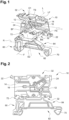
Figure 1 is a perspective schematic view of a withdrawable connector and a fixing foot according to one embodiment of the invention; -
Figure 2 is a schematic view of a connection assembly according to one embodiment of the invention; -
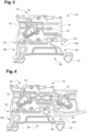
Figure 3 is a schematic view of a withdrawable connector and a fixing foot according to one embodiment of the invention; and -
Figure 4 is a schematic view of a withdrawable connector, an external socket and a fixing foot according to one embodiment of the invention. - In the following detailed description of the figures defined above, the same elements or elements fulfilling identical functions may retain the same references so as to simplify the understanding of the invention.
-
Figure 1 and4 describes awithdrawable connector 10 comprising an insulating body having a firstconnector cooperation area 32 and extending in a first extension direction E1 from said firstconnector cooperation area 32. In the sense of the present invention, an insulating body extending in a first extension direction E1 does not necessary mean that the first extension direction E1 defines the largest dimension of said insulating body. In particular, the fact that the insulating body extends in the first extension direction E1 means that the insulating body has a certain thickness in the first extension direction E1. - The first
connector cooperation area 32 defines a bottom surface BS, said bottom surface BF being transverse to the first extension direction E1. - The
withdrawable connector 10 comprises a top surface TS defined by a secondconnector cooperation area 32, said top surface TS being opposed to the bottom surface BS, and transverse to the first extension direction E1. In other words, the insulating body extends in the first extension direction E1 from the bottom surface BS towards the top surface TS. Advantageously, the top surface is substantially parallel to the bottom surface. In the sense of the present invention, substantially parallel means having an angle comprised between -10° and 10°. - The
withdrawable connector 10 comprises aconductive bar 16 disposed in the insulating body and aconnection socket 14. Theconnection socket 14 is arranged to cooperate with anexternal socket 15 by a relative movement in an insertion direction I transverse to the first extension direction E1. Said relative movement electrically connect saidexternal socket 15 to theconductive bar 16 when theexternal socket 15 cooperates with theconnection socket 14. In the sense of the present invention, transverse means perpendicular or substantially perpendicular. Substantially perpendicular means having an angle comprised between 80° and 100°. Such a configuration, and more particularly the cooperation of theexternal socket 15 with theconnection socket 14 by a relative movement in an insertion direction I transverse to the first extension direction E1 facilitates the insertion of saidexternal connection 15. - The
connection socket 14 comprises two opposing fixing recesses, each one being configured to receive a fixing unit of theexternal socket 15. Such a configuration allows securing the cooperation between theconnection socket 14 and theexternal socket 15. - The
withdrawable connector 10 also comprises aconnection terminal 12 arranged to cooperate with an external conductor by a relative movement in a direction opposed to the insertion direction I. Such a configuration, and more particularly the cooperation of the external conductor with theconnection terminal 12 by a relative movement in the insertion direction I transverse to the first extension direction E1 facilitates the insertion of said external conductor. Saidconnection terminal 12 is configured to electrically connect the external conductor to theconductive bar 16 when the external conductor cooperates with theconnection terminal 12. - The
connection terminal 12 comprises aleaf spring 24 configured to maintain the external conductor in an inserted position in whichconnection terminal 12 cooperate with said external conductor. Such a configuration allows securing the cooperation between theconnection terminal 12 and the external conductor. - The
withdrawable connector 10 comprises a displacement portion arranged to cooperate with a displacement element. Said displacement element imposing a stress in a direction opposed to the insertion direction I or a direction oblique with respect to the direction opposed to the insertion direction I. Said stress imposed by the displacement element moves theleaf spring 24 to release the external conductor of the inserted position. Such a configuration allows the external conductor to be released from the inserted position. - The
withdrawable connector 10 comprises a front face FS defined by theconnection socket 14 and opposed to a back face BF, said front face FS and back face BF being transverse to the insertion direction I. - The
withdrawable connector 10 comprises a retainingfinger 22 configured to interface with anexternal finger 23 of theexternal socket 15 in a retained position, said retainingfinger 22 extending substantially in the insertion direction I. Such a configuration allows securing the cooperation between theconnection socket 14 and theexternal socket 15. - As illustrated in
figures 2 and3 , the twoconnector cooperation areas 32 are configured to cooperate with a fixingfoot 60, in a mounting position by a relative displacement of thewithdrawable connector 10 in a longitudinal extension direction L. Said longitudinal extension direction L being transverse to both insertion direction I and first extension direction E1. Such a configuration allows thewithdrawable connector 10 to cooperate efficiently with the fixingfoot 60. Indeed, the fixingfoot 60 can cooperate with thewithdrawable connector 10 using any of theconnector cooperation areas 32. - Each one of the
connector cooperation areas 32 comprises a detent system including a first portion provided on the fixingfoot 60 and a second portion provided on thewithdrawable connector 10. The detent system being configured to maintain the mounting position when a force below a certain threshold is applied to thewithdrawable connector 10 and the fixingfoot 60 according to the longitudinal extension direction L. Such a configuration allows to secure the fixingfoot 60 to thewithdrawable connector 10 and to provide a compact design. - The
withdrawable connector 10 comprises two lateral faces LF which are substantially parallel to each other, said lateral faces LF being transverse to the longitudinal extension direction L. Such a configuration allows to place thewithdrawable connector 10 next or between other connectors. Said other connectors having a face in contact with the lateral faces LF of thewithdrawable connector 10. - The invention also relates to a fixing
foot 60 comprising a fixingportion 82 configured to be fixed to a support. - According to an embodiment the fixing
portion 82 comprises at least two fixing members configured to cooperate with two screws configured to be inserted in the support. Such a configuration allows the fixingfoot 60 to be well fixed to the support. - According to an embodiment the fixing
portion 82 comprises at least twoattachment members foot 60 to be fixed on a Ω-shaped rail. According to an embodiment, the Ω-shaped rail may be a DIN rail for example. - According to an embodiment the fixing portion comprises a fixing surface configured to cooperate with a support surface substantially plane. For the purposes of the present invention, substantially plane means "plane" or "plane to within 5%". Such a configuration allows the connection assembly to be fixed on a support surface substantially plane.
- According to an embodiment the fixing
portion 82 comprises at least two permanent fasteners configured to cooperate by snap-fit with the support. Such a configuration allows the fixingfoot 60 to be well fixed to the support. Such a configuration allows the fixingfoot 60 to quickly fixed to the support. - The fixing
foot 60 also comprises a body having afoot cooperation area 72 configured to cooperate with aconnector cooperation area 32, said body extending in a second extension direction E2 from the fixingportion 82. In the sense of the present invention, a body extending in a second extension direction E2 does not necessary mean that the second extension direction E2 defines the largest dimension of said body. In particular, the fact that the body extends in the second extension direction E2 means that the body has a certain thickness in the second extension direction E2. - The fixing
foot 60 comprises arecess 84 extending along a recess direction R transverse to the second extension direction E2. Said recess is comprised between the fixingpotion 82 and thefoot cooperation area 72. Such a configuration allows facilitate the cooperation between the fixingfoot 60 and thewithdrawable connector 10. More particularly, such a configuration allows the external finger to be released from the retained position. - According to a specific embodiment, the
foot cooperation area 72 comprises a detent system including a first portion provided on the fixingfoot 60 and a second portion in thewithdrawable connector 10, the detent system being configured to maintain thefoot cooperation area 72 and thewithdrawable connector 10 in a mounting position when a force below a certain threshold is applied to thewithdrawable connector 10 and the fixingfoot 60 according to a foot extension direction F, said foot extension direction F being transverse to both recess direction R and second extension direction E2. Such a configuration allows to secure the fixingfoot 60 to thewithdrawable connector 10 and to provide a compact design. - The present invention also relates to a connection assembly comprising a
withdrawable connector 10 and a fixingfoot 60 configured to cooperate with thewithdrawable connector 10 in the mounting position. - The fixing
foot 10, thewithdrawable connector 60 and the retainingfinger 22 create an insertion space configured to guide the external finger into the retained position. Such a configuration facilitates the retained position setting up. Such a configuration allows the external finger to be released from the retained position.
Claims (10)
- A connection assembly comprising a withdrawable connector (10) and a fixing foot (60) configured to cooperate with the withdrawable connector (10) in two mounting positions,the withdrawable connector (10) comprising:an insulating body having two connector cooperation areas (32), each being configured to cooperate, in a corresponding mounting position, with the fixing foot (60) configured to be fixed to a support, the two connector cooperation areas (32) being located on two opposite faces of the insulating body, said insulating body extending in a first extension direction (E1) from the connector cooperation area (32);a conductive bar (16) disposed in the insulating body,a connection socket (14) arranged to cooperate with an external socket (15);said connection socket being configured to electrically connect the external socket (15) to the conductive bar (16) when the external socket (15) cooperates with the connection socket (14); andwherein the connection socket (14) is arranged for the external socket (15) to cooperate with said connection socket (14) by a relative movement in an insertion direction (I) transverse to the first extension direction (E1);wherein the withdrawable connector (10) comprises a retaining finger (22) configured to interface with an external finger (23) of the external socket (15) in a retained position, said retaining finger (22) extending substantially in the insertion direction (I),the fixing foot (60) comprising :wherein the fixing foot (60) comprises a recess (84) extending along a recess direction (R) transverse to the second extension direction (E2).a fixing portion (82) configured to be fixed to the support; anda body having a foot cooperation area (72) configured to cooperate with the withdrawable connector (10), said body extending in a second extension direction (E2) from the fixing portion (82),
- The connection assembly of claim 1, wherein the connector cooperation area (32) defines a bottom surface (BS), said bottom surface (BF) being transverse to the first extension direction (E1).
- The connection assembly of claim 2, wherein the withdrawable connector (10) comprises a top surface (TS) opposed to the bottom surface (BS), said top surface (TS) being transverse to the first extension direction (E1).
- The connection assembly according to any one of claims 1 to 3, wherein the withdrawable connector (10) comprises a front face (FS) defined by the connection socket (14) and opposed to a back face (BF), said front face (FS) and back face (BF) being transverse to the insertion direction (I).
- The connection assembly according to any one of claims 1 to 4, wherein the connector cooperation areas (32) are configured to cooperate with the fixing foot (60) in a mounting position by a relative displacement of the withdrawable connector in a longitudinal extension direction (L), said longitudinal extension direction (L) being transverse to both insertion direction (I) and first extension direction (E1).
- The connection assembly of claim 5, wherein the withdrawable connector (10) comprises two lateral faces (LF) which are substantially parallel to each other, said lateral faces (LF) being transverse to the longitudinal extension direction (L).
- The connection assembly according to any one of claims 1 to 6, wherein the withdrawable connector (10) comprises a connection terminal (12) arranged to cooperate with an external conductor by a relative movement opposite to the insertion direction (I).
- The connection assembly according to any one of claims 1 to 7, wherein each one of the connector cooperation areas (32) comprises a detent system including a first portion provided on the fixing foot (60) and a second portion provided on the withdrawable connector (10), the detent system being configured to maintain the mounting position when a force below a certain threshold is applied to the withdrawable connector (10) and the fixing foot (60) according to the longitudinal extension direction (L).
- The connection assembly according to any one of claims 1 to 8, wherein the foot cooperation area (72) comprises a detent system including a first portion provided on the fixing foot (60) and a second portion in the withdrawable connector (10), the detent system being configured to maintain the foot cooperation area (72) and the withdrawable connector (10) in a mounting position when a force below a certain threshold is applied to the withdrawable connector (10) and the fixing foot (60) according to a foot extension direction (F), said foot extension direction (F) being transverse to both recess direction (R) and second extension direction (E2).
- The connection assembly of claim 9, wherein the fixing foot (60), the withdrawable connector (10) and the retaining finger (22) create an insertion space configured to guide the external finger into the retained position.
Priority Applications (2)
| Application Number | Priority Date | Filing Date | Title |
|---|---|---|---|
| EP18306746.1A EP3671963B1 (en) | 2018-12-19 | 2018-12-19 | Connection assembly comprising a withdrawable connector and a fixing foot configured to cooperate with the withdrawable connector |
| CN201911312409.6A CN111342299B (en) | 2018-12-19 | 2019-12-18 | Connection assembly |
Applications Claiming Priority (1)
| Application Number | Priority Date | Filing Date | Title |
|---|---|---|---|
| EP18306746.1A EP3671963B1 (en) | 2018-12-19 | 2018-12-19 | Connection assembly comprising a withdrawable connector and a fixing foot configured to cooperate with the withdrawable connector |
Publications (2)
| Publication Number | Publication Date |
|---|---|
| EP3671963A1 EP3671963A1 (en) | 2020-06-24 |
| EP3671963B1 true EP3671963B1 (en) | 2024-02-21 |
Family
ID=65278158
Family Applications (1)
| Application Number | Title | Priority Date | Filing Date |
|---|---|---|---|
| EP18306746.1A Active EP3671963B1 (en) | 2018-12-19 | 2018-12-19 | Connection assembly comprising a withdrawable connector and a fixing foot configured to cooperate with the withdrawable connector |
Country Status (2)
| Country | Link |
|---|---|
| EP (1) | EP3671963B1 (en) |
| CN (1) | CN111342299B (en) |
Family Cites Families (4)
| Publication number | Priority date | Publication date | Assignee | Title |
|---|---|---|---|---|
| DE3014755A1 (en) * | 1980-04-17 | 1981-10-22 | C.A. Weidmüller KG, 4930 Detmold | MIXABLE BLOCK FOR ELECTRICAL CONNECTORS |
| US6146213A (en) * | 1998-12-10 | 2000-11-14 | Yoon; Heung-Sik | Wire connection with exchangeable securing member for electric connection terminal assembly |
| FR2824961B1 (en) | 2001-05-15 | 2004-02-27 | Entrelec | HANGING SYSTEM AND ELEMENTS IMPLEMENTING THIS SYSTEM |
| EP3076486B1 (en) * | 2015-03-30 | 2020-04-22 | TE Connectivity Services GmbH | Row of releasable connectors for junction block |
-
2018
- 2018-12-19 EP EP18306746.1A patent/EP3671963B1/en active Active
-
2019
- 2019-12-18 CN CN201911312409.6A patent/CN111342299B/en active Active
Also Published As
| Publication number | Publication date |
|---|---|
| CN111342299A (en) | 2020-06-26 |
| EP3671963A1 (en) | 2020-06-24 |
| CN111342299B (en) | 2023-09-19 |
Similar Documents
| Publication | Publication Date | Title |
|---|---|---|
| US6203364B1 (en) | Electrical connector having slide clip attachment | |
| US9054456B2 (en) | Power connector assembly having an alignment body | |
| US3474381A (en) | Lamp connection and mounting devices | |
| CN107240811B (en) | Electrical plug-in connector | |
| US7232324B2 (en) | Electrical connector bridge arrangement with release means | |
| CN111864473A (en) | Plug connector for electrical plug connection and electrical plug connection formed therefrom | |
| US11228139B2 (en) | Plug connector of an electrical plug connection and set comprising a plug connector and functional element | |
| KR102530744B1 (en) | Terminal assembly with a bus bar | |
| US9293860B1 (en) | Connector for a vehicle | |
| US9537259B2 (en) | Plug-type connector arrangement and coding element therefor and method for coding a plug-type connector arrangement | |
| EP2698877B1 (en) | Contact and connector | |
| KR20200000709U (en) | Plug-in connector arrangement | |
| EP3091618B1 (en) | Female contact and power-supply connector | |
| US20200169026A1 (en) | Connector | |
| JPH0748390B2 (en) | Electrical connector | |
| US20230076634A1 (en) | Plug Connector and Connector Assembly | |
| US9478903B2 (en) | Connecting terminal | |
| US11196193B2 (en) | Conductor terminal, assortment of at least one base module and differently designed conductor connecting modules of a conductor terminal, and conductor terminal block | |
| CN102939430A (en) | Mounting arrangement for door actuator | |
| EP3671963A1 (en) | Connection assembly comprising a withdrawable connector and a fixing foot configured to cooperate with the withdrawable connector | |
| KR200469373Y1 (en) | Electrical connector | |
| CN109845038B (en) | Electrical connection system with additional leaf springs | |
| CN109361112B (en) | Connector | |
| CN220138726U (en) | Contact connector | |
| CN118712772A (en) | Busbar contact element, and terminal block and device having a busbar and a busbar contact element |
Legal Events
| Date | Code | Title | Description |
|---|---|---|---|
| PUAI | Public reference made under article 153(3) epc to a published international application that has entered the european phase |
Free format text: ORIGINAL CODE: 0009012 |
|
| STAA | Information on the status of an ep patent application or granted ep patent |
Free format text: STATUS: THE APPLICATION HAS BEEN PUBLISHED |
|
| AK | Designated contracting states |
Kind code of ref document: A1 Designated state(s): AL AT BE BG CH CY CZ DE DK EE ES FI FR GB GR HR HU IE IS IT LI LT LU LV MC MK MT NL NO PL PT RO RS SE SI SK SM TR |
|
| AX | Request for extension of the european patent |
Extension state: BA ME |
|
| STAA | Information on the status of an ep patent application or granted ep patent |
Free format text: STATUS: REQUEST FOR EXAMINATION WAS MADE |
|
| 17P | Request for examination filed |
Effective date: 20201210 |
|
| RBV | Designated contracting states (corrected) |
Designated state(s): AL AT BE BG CH CY CZ DE DK EE ES FI FR GB GR HR HU IE IS IT LI LT LU LV MC MK MT NL NO PL PT RO RS SE SI SK SM TR |
|
| RIN1 | Information on inventor provided before grant (corrected) |
Inventor name: VILLARD, ROMAIN Inventor name: VILLARDIER, YANNICK Inventor name: DELIGNY, CHARLOTTE |
|
| STAA | Information on the status of an ep patent application or granted ep patent |
Free format text: STATUS: EXAMINATION IS IN PROGRESS |
|
| 17Q | First examination report despatched |
Effective date: 20211112 |
|
| GRAP | Despatch of communication of intention to grant a patent |
Free format text: ORIGINAL CODE: EPIDOSNIGR1 |
|
| STAA | Information on the status of an ep patent application or granted ep patent |
Free format text: STATUS: GRANT OF PATENT IS INTENDED |
|
| INTG | Intention to grant announced |
Effective date: 20231004 |
|
| GRAS | Grant fee paid |
Free format text: ORIGINAL CODE: EPIDOSNIGR3 |
|
| GRAA | (expected) grant |
Free format text: ORIGINAL CODE: 0009210 |
|
| STAA | Information on the status of an ep patent application or granted ep patent |
Free format text: STATUS: THE PATENT HAS BEEN GRANTED |
|
| AK | Designated contracting states |
Kind code of ref document: B1 Designated state(s): AL AT BE BG CH CY CZ DE DK EE ES FI FR GB GR HR HU IE IS IT LI LT LU LV MC MK MT NL NO PL PT RO RS SE SI SK SM TR |
|
| REG | Reference to a national code |
Ref country code: GB Ref legal event code: FG4D |
|
| REG | Reference to a national code |
Ref country code: CH Ref legal event code: EP |
|
| REG | Reference to a national code |
Ref country code: DE Ref legal event code: R096 Ref document number: 602018065480 Country of ref document: DE |
|
| REG | Reference to a national code |
Ref country code: IE Ref legal event code: FG4D |
|
| REG | Reference to a national code |
Ref country code: LT Ref legal event code: MG9D |
|
| REG | Reference to a national code |
Ref country code: NL Ref legal event code: MP Effective date: 20240221 |
|
| PG25 | Lapsed in a contracting state [announced via postgrant information from national office to epo] |
Ref country code: IS Free format text: LAPSE BECAUSE OF FAILURE TO SUBMIT A TRANSLATION OF THE DESCRIPTION OR TO PAY THE FEE WITHIN THE PRESCRIBED TIME-LIMIT Effective date: 20240621 |
|
| PG25 | Lapsed in a contracting state [announced via postgrant information from national office to epo] |
Ref country code: LT Free format text: LAPSE BECAUSE OF FAILURE TO SUBMIT A TRANSLATION OF THE DESCRIPTION OR TO PAY THE FEE WITHIN THE PRESCRIBED TIME-LIMIT Effective date: 20240221 |
|
| PG25 | Lapsed in a contracting state [announced via postgrant information from national office to epo] |
Ref country code: GR Free format text: LAPSE BECAUSE OF FAILURE TO SUBMIT A TRANSLATION OF THE DESCRIPTION OR TO PAY THE FEE WITHIN THE PRESCRIBED TIME-LIMIT Effective date: 20240522 |
|
| REG | Reference to a national code |
Ref country code: AT Ref legal event code: MK05 Ref document number: 1659939 Country of ref document: AT Kind code of ref document: T Effective date: 20240221 |
|
| PG25 | Lapsed in a contracting state [announced via postgrant information from national office to epo] |
Ref country code: HR Free format text: LAPSE BECAUSE OF FAILURE TO SUBMIT A TRANSLATION OF THE DESCRIPTION OR TO PAY THE FEE WITHIN THE PRESCRIBED TIME-LIMIT Effective date: 20240221 Ref country code: NL Free format text: LAPSE BECAUSE OF FAILURE TO SUBMIT A TRANSLATION OF THE DESCRIPTION OR TO PAY THE FEE WITHIN THE PRESCRIBED TIME-LIMIT Effective date: 20240221 Ref country code: RS Free format text: LAPSE BECAUSE OF FAILURE TO SUBMIT A TRANSLATION OF THE DESCRIPTION OR TO PAY THE FEE WITHIN THE PRESCRIBED TIME-LIMIT Effective date: 20240521 |
|
| PG25 | Lapsed in a contracting state [announced via postgrant information from national office to epo] |
Ref country code: ES Free format text: LAPSE BECAUSE OF FAILURE TO SUBMIT A TRANSLATION OF THE DESCRIPTION OR TO PAY THE FEE WITHIN THE PRESCRIBED TIME-LIMIT Effective date: 20240221 |
|
| PG25 | Lapsed in a contracting state [announced via postgrant information from national office to epo] |
Ref country code: AT Free format text: LAPSE BECAUSE OF FAILURE TO SUBMIT A TRANSLATION OF THE DESCRIPTION OR TO PAY THE FEE WITHIN THE PRESCRIBED TIME-LIMIT Effective date: 20240221 |
|
| PG25 | Lapsed in a contracting state [announced via postgrant information from national office to epo] |
Ref country code: RS Free format text: LAPSE BECAUSE OF FAILURE TO SUBMIT A TRANSLATION OF THE DESCRIPTION OR TO PAY THE FEE WITHIN THE PRESCRIBED TIME-LIMIT Effective date: 20240521 Ref country code: NO Free format text: LAPSE BECAUSE OF FAILURE TO SUBMIT A TRANSLATION OF THE DESCRIPTION OR TO PAY THE FEE WITHIN THE PRESCRIBED TIME-LIMIT Effective date: 20240521 Ref country code: NL Free format text: LAPSE BECAUSE OF FAILURE TO SUBMIT A TRANSLATION OF THE DESCRIPTION OR TO PAY THE FEE WITHIN THE PRESCRIBED TIME-LIMIT Effective date: 20240221 Ref country code: LT Free format text: LAPSE BECAUSE OF FAILURE TO SUBMIT A TRANSLATION OF THE DESCRIPTION OR TO PAY THE FEE WITHIN THE PRESCRIBED TIME-LIMIT Effective date: 20240221 Ref country code: IS Free format text: LAPSE BECAUSE OF FAILURE TO SUBMIT A TRANSLATION OF THE DESCRIPTION OR TO PAY THE FEE WITHIN THE PRESCRIBED TIME-LIMIT Effective date: 20240621 Ref country code: HR Free format text: LAPSE BECAUSE OF FAILURE TO SUBMIT A TRANSLATION OF THE DESCRIPTION OR TO PAY THE FEE WITHIN THE PRESCRIBED TIME-LIMIT Effective date: 20240221 Ref country code: GR Free format text: LAPSE BECAUSE OF FAILURE TO SUBMIT A TRANSLATION OF THE DESCRIPTION OR TO PAY THE FEE WITHIN THE PRESCRIBED TIME-LIMIT Effective date: 20240522 Ref country code: FI Free format text: LAPSE BECAUSE OF FAILURE TO SUBMIT A TRANSLATION OF THE DESCRIPTION OR TO PAY THE FEE WITHIN THE PRESCRIBED TIME-LIMIT Effective date: 20240221 Ref country code: ES Free format text: LAPSE BECAUSE OF FAILURE TO SUBMIT A TRANSLATION OF THE DESCRIPTION OR TO PAY THE FEE WITHIN THE PRESCRIBED TIME-LIMIT Effective date: 20240221 Ref country code: BG Free format text: LAPSE BECAUSE OF FAILURE TO SUBMIT A TRANSLATION OF THE DESCRIPTION OR TO PAY THE FEE WITHIN THE PRESCRIBED TIME-LIMIT Effective date: 20240221 Ref country code: AT Free format text: LAPSE BECAUSE OF FAILURE TO SUBMIT A TRANSLATION OF THE DESCRIPTION OR TO PAY THE FEE WITHIN THE PRESCRIBED TIME-LIMIT Effective date: 20240221 |
|
| PG25 | Lapsed in a contracting state [announced via postgrant information from national office to epo] |
Ref country code: PL Free format text: LAPSE BECAUSE OF FAILURE TO SUBMIT A TRANSLATION OF THE DESCRIPTION OR TO PAY THE FEE WITHIN THE PRESCRIBED TIME-LIMIT Effective date: 20240221 Ref country code: PT Free format text: LAPSE BECAUSE OF FAILURE TO SUBMIT A TRANSLATION OF THE DESCRIPTION OR TO PAY THE FEE WITHIN THE PRESCRIBED TIME-LIMIT Effective date: 20240621 |
|
| PG25 | Lapsed in a contracting state [announced via postgrant information from national office to epo] |
Ref country code: SE Free format text: LAPSE BECAUSE OF FAILURE TO SUBMIT A TRANSLATION OF THE DESCRIPTION OR TO PAY THE FEE WITHIN THE PRESCRIBED TIME-LIMIT Effective date: 20240221 Ref country code: PT Free format text: LAPSE BECAUSE OF FAILURE TO SUBMIT A TRANSLATION OF THE DESCRIPTION OR TO PAY THE FEE WITHIN THE PRESCRIBED TIME-LIMIT Effective date: 20240621 Ref country code: PL Free format text: LAPSE BECAUSE OF FAILURE TO SUBMIT A TRANSLATION OF THE DESCRIPTION OR TO PAY THE FEE WITHIN THE PRESCRIBED TIME-LIMIT Effective date: 20240221 Ref country code: LV Free format text: LAPSE BECAUSE OF FAILURE TO SUBMIT A TRANSLATION OF THE DESCRIPTION OR TO PAY THE FEE WITHIN THE PRESCRIBED TIME-LIMIT Effective date: 20240221 |
|
| PG25 | Lapsed in a contracting state [announced via postgrant information from national office to epo] |
Ref country code: DK Free format text: LAPSE BECAUSE OF FAILURE TO SUBMIT A TRANSLATION OF THE DESCRIPTION OR TO PAY THE FEE WITHIN THE PRESCRIBED TIME-LIMIT Effective date: 20240221 |
|
| PG25 | Lapsed in a contracting state [announced via postgrant information from national office to epo] |
Ref country code: SM Free format text: LAPSE BECAUSE OF FAILURE TO SUBMIT A TRANSLATION OF THE DESCRIPTION OR TO PAY THE FEE WITHIN THE PRESCRIBED TIME-LIMIT Effective date: 20240221 |
|
| PG25 | Lapsed in a contracting state [announced via postgrant information from national office to epo] |
Ref country code: EE Free format text: LAPSE BECAUSE OF FAILURE TO SUBMIT A TRANSLATION OF THE DESCRIPTION OR TO PAY THE FEE WITHIN THE PRESCRIBED TIME-LIMIT Effective date: 20240221 Ref country code: CZ Free format text: LAPSE BECAUSE OF FAILURE TO SUBMIT A TRANSLATION OF THE DESCRIPTION OR TO PAY THE FEE WITHIN THE PRESCRIBED TIME-LIMIT Effective date: 20240221 |
|
| PG25 | Lapsed in a contracting state [announced via postgrant information from national office to epo] |
Ref country code: SK Free format text: LAPSE BECAUSE OF FAILURE TO SUBMIT A TRANSLATION OF THE DESCRIPTION OR TO PAY THE FEE WITHIN THE PRESCRIBED TIME-LIMIT Effective date: 20240221 |
|
| PG25 | Lapsed in a contracting state [announced via postgrant information from national office to epo] |
Ref country code: SM Free format text: LAPSE BECAUSE OF FAILURE TO SUBMIT A TRANSLATION OF THE DESCRIPTION OR TO PAY THE FEE WITHIN THE PRESCRIBED TIME-LIMIT Effective date: 20240221 Ref country code: SK Free format text: LAPSE BECAUSE OF FAILURE TO SUBMIT A TRANSLATION OF THE DESCRIPTION OR TO PAY THE FEE WITHIN THE PRESCRIBED TIME-LIMIT Effective date: 20240221 Ref country code: RO Free format text: LAPSE BECAUSE OF FAILURE TO SUBMIT A TRANSLATION OF THE DESCRIPTION OR TO PAY THE FEE WITHIN THE PRESCRIBED TIME-LIMIT Effective date: 20240221 Ref country code: EE Free format text: LAPSE BECAUSE OF FAILURE TO SUBMIT A TRANSLATION OF THE DESCRIPTION OR TO PAY THE FEE WITHIN THE PRESCRIBED TIME-LIMIT Effective date: 20240221 Ref country code: DK Free format text: LAPSE BECAUSE OF FAILURE TO SUBMIT A TRANSLATION OF THE DESCRIPTION OR TO PAY THE FEE WITHIN THE PRESCRIBED TIME-LIMIT Effective date: 20240221 Ref country code: CZ Free format text: LAPSE BECAUSE OF FAILURE TO SUBMIT A TRANSLATION OF THE DESCRIPTION OR TO PAY THE FEE WITHIN THE PRESCRIBED TIME-LIMIT Effective date: 20240221 |
|
| REG | Reference to a national code |
Ref country code: DE Ref legal event code: R097 Ref document number: 602018065480 Country of ref document: DE |
|
| REG | Reference to a national code |
Ref country code: DE Ref legal event code: R081 Ref document number: 602018065480 Country of ref document: DE Owner name: TE CONNECTIVITY SOLUTIONS GMBH, CH Free format text: FORMER OWNER: TYCO ELECTRONICS FRANCE SAS, PONTOISE, FR |
|
| PG25 | Lapsed in a contracting state [announced via postgrant information from national office to epo] |
Ref country code: IT Free format text: LAPSE BECAUSE OF FAILURE TO SUBMIT A TRANSLATION OF THE DESCRIPTION OR TO PAY THE FEE WITHIN THE PRESCRIBED TIME-LIMIT Effective date: 20240221 |
|
| REG | Reference to a national code |
Ref country code: GB Ref legal event code: 732E Free format text: REGISTERED BETWEEN 20241114 AND 20241120 |
|
| PLBE | No opposition filed within time limit |
Free format text: ORIGINAL CODE: 0009261 |
|
| STAA | Information on the status of an ep patent application or granted ep patent |
Free format text: STATUS: NO OPPOSITION FILED WITHIN TIME LIMIT |
|
| PG25 | Lapsed in a contracting state [announced via postgrant information from national office to epo] |
Ref country code: IT Free format text: LAPSE BECAUSE OF FAILURE TO SUBMIT A TRANSLATION OF THE DESCRIPTION OR TO PAY THE FEE WITHIN THE PRESCRIBED TIME-LIMIT Effective date: 20240221 |
|
| 26N | No opposition filed |
Effective date: 20241122 |
|
| PG25 | Lapsed in a contracting state [announced via postgrant information from national office to epo] |
Ref country code: SI Free format text: LAPSE BECAUSE OF FAILURE TO SUBMIT A TRANSLATION OF THE DESCRIPTION OR TO PAY THE FEE WITHIN THE PRESCRIBED TIME-LIMIT Effective date: 20240221 |
|
| PG25 | Lapsed in a contracting state [announced via postgrant information from national office to epo] |
Ref country code: MC Free format text: LAPSE BECAUSE OF FAILURE TO SUBMIT A TRANSLATION OF THE DESCRIPTION OR TO PAY THE FEE WITHIN THE PRESCRIBED TIME-LIMIT Effective date: 20240221 |
|
| REG | Reference to a national code |
Ref country code: CH Ref legal event code: PL |
|
| PG25 | Lapsed in a contracting state [announced via postgrant information from national office to epo] |
Ref country code: LU Free format text: LAPSE BECAUSE OF NON-PAYMENT OF DUE FEES Effective date: 20241219 |
|
| REG | Reference to a national code |
Ref country code: BE Ref legal event code: MM Effective date: 20241231 |
|
| PG25 | Lapsed in a contracting state [announced via postgrant information from national office to epo] |
Ref country code: BE Free format text: LAPSE BECAUSE OF NON-PAYMENT OF DUE FEES Effective date: 20241231 |
|
| PG25 | Lapsed in a contracting state [announced via postgrant information from national office to epo] |
Ref country code: CH Free format text: LAPSE BECAUSE OF NON-PAYMENT OF DUE FEES Effective date: 20241231 |
|
| PG25 | Lapsed in a contracting state [announced via postgrant information from national office to epo] |
Ref country code: IE Free format text: LAPSE BECAUSE OF NON-PAYMENT OF DUE FEES Effective date: 20241219 |
|
| PGFP | Annual fee paid to national office [announced via postgrant information from national office to epo] |
Ref country code: DE Payment date: 20250930 Year of fee payment: 8 |
|
| PGFP | Annual fee paid to national office [announced via postgrant information from national office to epo] |
Ref country code: GB Payment date: 20251001 Year of fee payment: 8 |
|
| PGFP | Annual fee paid to national office [announced via postgrant information from national office to epo] |
Ref country code: FR Payment date: 20251008 Year of fee payment: 8 |
|
| PG25 | Lapsed in a contracting state [announced via postgrant information from national office to epo] |
Ref country code: CY Free format text: LAPSE BECAUSE OF FAILURE TO SUBMIT A TRANSLATION OF THE DESCRIPTION OR TO PAY THE FEE WITHIN THE PRESCRIBED TIME-LIMIT Effective date: 20240221 |
|
| PG25 | Lapsed in a contracting state [announced via postgrant information from national office to epo] |
Ref country code: TR Free format text: LAPSE BECAUSE OF FAILURE TO SUBMIT A TRANSLATION OF THE DESCRIPTION OR TO PAY THE FEE WITHIN THE PRESCRIBED TIME-LIMIT Effective date: 20240221 |
|
| PG25 | Lapsed in a contracting state [announced via postgrant information from national office to epo] |
Ref country code: HU Free format text: LAPSE BECAUSE OF FAILURE TO SUBMIT A TRANSLATION OF THE DESCRIPTION OR TO PAY THE FEE WITHIN THE PRESCRIBED TIME-LIMIT; INVALID AB INITIO Effective date: 20181219 |