EP3671948A2 - Foldable electronic device with controlled antenna sagnal intensity - Google Patents
Foldable electronic device with controlled antenna sagnal intensity Download PDFInfo
- Publication number
- EP3671948A2 EP3671948A2 EP19205700.8A EP19205700A EP3671948A2 EP 3671948 A2 EP3671948 A2 EP 3671948A2 EP 19205700 A EP19205700 A EP 19205700A EP 3671948 A2 EP3671948 A2 EP 3671948A2
- Authority
- EP
- European Patent Office
- Prior art keywords
- state
- housing
- electronic device
- housing structure
- processor
- Prior art date
- Legal status (The legal status is an assumption and is not a legal conclusion. Google has not performed a legal analysis and makes no representation as to the accuracy of the status listed.)
- Granted
Links
Images

Classifications
-
- H—ELECTRICITY
- H01—ELECTRIC ELEMENTS
- H01Q—ANTENNAS, i.e. RADIO AERIALS
- H01Q1/00—Details of, or arrangements associated with, antennas
- H01Q1/12—Supports; Mounting means
- H01Q1/22—Supports; Mounting means by structural association with other equipment or articles
- H01Q1/24—Supports; Mounting means by structural association with other equipment or articles with receiving set
- H01Q1/241—Supports; Mounting means by structural association with other equipment or articles with receiving set used in mobile communications, e.g. GSM
- H01Q1/242—Supports; Mounting means by structural association with other equipment or articles with receiving set used in mobile communications, e.g. GSM specially adapted for hand-held use
- H01Q1/243—Supports; Mounting means by structural association with other equipment or articles with receiving set used in mobile communications, e.g. GSM specially adapted for hand-held use with built-in antennas
-
- G—PHYSICS
- G06—COMPUTING OR CALCULATING; COUNTING
- G06F—ELECTRIC DIGITAL DATA PROCESSING
- G06F1/00—Details not covered by groups G06F3/00 - G06F13/00 and G06F21/00
- G06F1/16—Constructional details or arrangements
- G06F1/1613—Constructional details or arrangements for portable computers
- G06F1/1615—Constructional details or arrangements for portable computers with several enclosures having relative motions, each enclosure supporting at least one I/O or computing function
- G06F1/1616—Constructional details or arrangements for portable computers with several enclosures having relative motions, each enclosure supporting at least one I/O or computing function with folding flat displays, e.g. laptop computers or notebooks having a clamshell configuration, with body parts pivoting to an open position around an axis parallel to the plane they define in closed position
-
- G—PHYSICS
- G06—COMPUTING OR CALCULATING; COUNTING
- G06F—ELECTRIC DIGITAL DATA PROCESSING
- G06F1/00—Details not covered by groups G06F3/00 - G06F13/00 and G06F21/00
- G06F1/16—Constructional details or arrangements
- G06F1/1613—Constructional details or arrangements for portable computers
- G06F1/1633—Constructional details or arrangements of portable computers not specific to the type of enclosures covered by groups G06F1/1615 - G06F1/1626
- G06F1/1637—Details related to the display arrangement, including those related to the mounting of the display in the housing
- G06F1/1641—Details related to the display arrangement, including those related to the mounting of the display in the housing the display being formed by a plurality of foldable display components
-
- G—PHYSICS
- G06—COMPUTING OR CALCULATING; COUNTING
- G06F—ELECTRIC DIGITAL DATA PROCESSING
- G06F1/00—Details not covered by groups G06F3/00 - G06F13/00 and G06F21/00
- G06F1/16—Constructional details or arrangements
- G06F1/1613—Constructional details or arrangements for portable computers
- G06F1/1633—Constructional details or arrangements of portable computers not specific to the type of enclosures covered by groups G06F1/1615 - G06F1/1626
- G06F1/1637—Details related to the display arrangement, including those related to the mounting of the display in the housing
- G06F1/1652—Details related to the display arrangement, including those related to the mounting of the display in the housing the display being flexible, e.g. mimicking a sheet of paper, or rollable
-
- G—PHYSICS
- G06—COMPUTING OR CALCULATING; COUNTING
- G06F—ELECTRIC DIGITAL DATA PROCESSING
- G06F1/00—Details not covered by groups G06F3/00 - G06F13/00 and G06F21/00
- G06F1/16—Constructional details or arrangements
- G06F1/1613—Constructional details or arrangements for portable computers
- G06F1/1633—Constructional details or arrangements of portable computers not specific to the type of enclosures covered by groups G06F1/1615 - G06F1/1626
- G06F1/1656—Details related to functional adaptations of the enclosure, e.g. to provide protection against EMI, shock, water, or to host detachable peripherals like a mouse or removable expansions units like PCMCIA cards, or to provide access to internal components for maintenance or to removable storage supports like CDs or DVDs, or to mechanically mount accessories
-
- G—PHYSICS
- G06—COMPUTING OR CALCULATING; COUNTING
- G06F—ELECTRIC DIGITAL DATA PROCESSING
- G06F1/00—Details not covered by groups G06F3/00 - G06F13/00 and G06F21/00
- G06F1/16—Constructional details or arrangements
- G06F1/1613—Constructional details or arrangements for portable computers
- G06F1/1633—Constructional details or arrangements of portable computers not specific to the type of enclosures covered by groups G06F1/1615 - G06F1/1626
- G06F1/1675—Miscellaneous details related to the relative movement between the different enclosures or enclosure parts
- G06F1/1677—Miscellaneous details related to the relative movement between the different enclosures or enclosure parts for detecting open or closed state or particular intermediate positions assumed by movable parts of the enclosure, e.g. detection of display lid position with respect to main body in a laptop, detection of opening of the cover of battery compartment
-
- G—PHYSICS
- G06—COMPUTING OR CALCULATING; COUNTING
- G06F—ELECTRIC DIGITAL DATA PROCESSING
- G06F1/00—Details not covered by groups G06F3/00 - G06F13/00 and G06F21/00
- G06F1/16—Constructional details or arrangements
- G06F1/1613—Constructional details or arrangements for portable computers
- G06F1/1633—Constructional details or arrangements of portable computers not specific to the type of enclosures covered by groups G06F1/1615 - G06F1/1626
- G06F1/1675—Miscellaneous details related to the relative movement between the different enclosures or enclosure parts
- G06F1/1681—Details related solely to hinges
-
- G—PHYSICS
- G06—COMPUTING OR CALCULATING; COUNTING
- G06F—ELECTRIC DIGITAL DATA PROCESSING
- G06F1/00—Details not covered by groups G06F3/00 - G06F13/00 and G06F21/00
- G06F1/16—Constructional details or arrangements
- G06F1/1613—Constructional details or arrangements for portable computers
- G06F1/1633—Constructional details or arrangements of portable computers not specific to the type of enclosures covered by groups G06F1/1615 - G06F1/1626
- G06F1/1684—Constructional details or arrangements related to integrated I/O peripherals not covered by groups G06F1/1635 - G06F1/1675
- G06F1/1698—Constructional details or arrangements related to integrated I/O peripherals not covered by groups G06F1/1635 - G06F1/1675 the I/O peripheral being a sending/receiving arrangement to establish a cordless communication link, e.g. radio or infrared link, integrated cellular phone
-
- H—ELECTRICITY
- H01—ELECTRIC ELEMENTS
- H01Q—ANTENNAS, i.e. RADIO AERIALS
- H01Q1/00—Details of, or arrangements associated with, antennas
- H01Q1/12—Supports; Mounting means
- H01Q1/22—Supports; Mounting means by structural association with other equipment or articles
- H01Q1/24—Supports; Mounting means by structural association with other equipment or articles with receiving set
- H01Q1/241—Supports; Mounting means by structural association with other equipment or articles with receiving set used in mobile communications, e.g. GSM
- H01Q1/242—Supports; Mounting means by structural association with other equipment or articles with receiving set used in mobile communications, e.g. GSM specially adapted for hand-held use
- H01Q1/245—Supports; Mounting means by structural association with other equipment or articles with receiving set used in mobile communications, e.g. GSM specially adapted for hand-held use with means for shaping the antenna pattern, e.g. in order to protect user against rf exposure
-
- H—ELECTRICITY
- H04—ELECTRIC COMMUNICATION TECHNIQUE
- H04B—TRANSMISSION
- H04B1/00—Details of transmission systems, not covered by a single one of groups H04B3/00 - H04B13/00; Details of transmission systems not characterised by the medium used for transmission
- H04B1/38—Transceivers, i.e. devices in which transmitter and receiver form a structural unit and in which at least one part is used for functions of transmitting and receiving
- H04B1/3827—Portable transceivers
- H04B1/3833—Hand-held transceivers
- H04B1/3838—Arrangements for reducing RF exposure to the user, e.g. by changing the shape of the transceiver while in use
-
- H—ELECTRICITY
- H04—ELECTRIC COMMUNICATION TECHNIQUE
- H04B—TRANSMISSION
- H04B17/00—Monitoring; Testing
- H04B17/10—Monitoring; Testing of transmitters
- H04B17/101—Monitoring; Testing of transmitters for measurement of specific parameters of the transmitter or components thereof
- H04B17/102—Power radiated at antenna
-
- H—ELECTRICITY
- H04—ELECTRIC COMMUNICATION TECHNIQUE
- H04M—TELEPHONIC COMMUNICATION
- H04M1/00—Substation equipment, e.g. for use by subscribers
- H04M1/02—Constructional features of telephone sets
- H04M1/0202—Portable telephone sets, e.g. cordless phones, mobile phones or bar type handsets
- H04M1/0206—Portable telephones comprising a plurality of mechanically joined movable body parts, e.g. hinged housings
- H04M1/0208—Portable telephones comprising a plurality of mechanically joined movable body parts, e.g. hinged housings characterized by the relative motions of the body parts
- H04M1/0214—Foldable telephones, i.e. with body parts pivoting to an open position around an axis parallel to the plane they define in closed position
- H04M1/0216—Foldable in one direction, i.e. using a one degree of freedom hinge
-
- H—ELECTRICITY
- H04—ELECTRIC COMMUNICATION TECHNIQUE
- H04M—TELEPHONIC COMMUNICATION
- H04M1/00—Substation equipment, e.g. for use by subscribers
- H04M1/02—Constructional features of telephone sets
- H04M1/0202—Portable telephone sets, e.g. cordless phones, mobile phones or bar type handsets
- H04M1/0206—Portable telephones comprising a plurality of mechanically joined movable body parts, e.g. hinged housings
- H04M1/0208—Portable telephones comprising a plurality of mechanically joined movable body parts, e.g. hinged housings characterized by the relative motions of the body parts
- H04M1/0214—Foldable telephones, i.e. with body parts pivoting to an open position around an axis parallel to the plane they define in closed position
- H04M1/0222—Foldable in two directions, i.e. using a two degree of freedom hinge
-
- H—ELECTRICITY
- H04—ELECTRIC COMMUNICATION TECHNIQUE
- H04M—TELEPHONIC COMMUNICATION
- H04M1/00—Substation equipment, e.g. for use by subscribers
- H04M1/02—Constructional features of telephone sets
- H04M1/0202—Portable telephone sets, e.g. cordless phones, mobile phones or bar type handsets
- H04M1/0206—Portable telephones comprising a plurality of mechanically joined movable body parts, e.g. hinged housings
- H04M1/0247—Portable telephones comprising a plurality of mechanically joined movable body parts, e.g. hinged housings comprising more than two body parts
-
- H—ELECTRICITY
- H04—ELECTRIC COMMUNICATION TECHNIQUE
- H04M—TELEPHONIC COMMUNICATION
- H04M1/00—Substation equipment, e.g. for use by subscribers
- H04M1/02—Constructional features of telephone sets
- H04M1/0202—Portable telephone sets, e.g. cordless phones, mobile phones or bar type handsets
- H04M1/0206—Portable telephones comprising a plurality of mechanically joined movable body parts, e.g. hinged housings
- H04M1/0208—Portable telephones comprising a plurality of mechanically joined movable body parts, e.g. hinged housings characterized by the relative motions of the body parts
- H04M1/0214—Foldable telephones, i.e. with body parts pivoting to an open position around an axis parallel to the plane they define in closed position
-
- H—ELECTRICITY
- H04—ELECTRIC COMMUNICATION TECHNIQUE
- H04M—TELEPHONIC COMMUNICATION
- H04M1/00—Substation equipment, e.g. for use by subscribers
- H04M1/02—Constructional features of telephone sets
- H04M1/0202—Portable telephone sets, e.g. cordless phones, mobile phones or bar type handsets
- H04M1/026—Details of the structure or mounting of specific components
- H04M1/0266—Details of the structure or mounting of specific components for a display module assembly
- H04M1/0268—Details of the structure or mounting of specific components for a display module assembly including a flexible display panel
-
- H—ELECTRICITY
- H04—ELECTRIC COMMUNICATION TECHNIQUE
- H04M—TELEPHONIC COMMUNICATION
- H04M2250/00—Details of telephonic subscriber devices
- H04M2250/22—Details of telephonic subscriber devices including a touch pad, a touch sensor or a touch detector
-
- H—ELECTRICITY
- H04—ELECTRIC COMMUNICATION TECHNIQUE
- H04W—WIRELESS COMMUNICATION NETWORKS
- H04W52/00—Power management, e.g. Transmission Power Control [TPC] or power classes
- H04W52/04—Transmission power control [TPC]
- H04W52/30—Transmission power control [TPC] using constraints in the total amount of available transmission power
- H04W52/36—Transmission power control [TPC] using constraints in the total amount of available transmission power with a discrete range or set of values, e.g. step size, ramping or offsets
- H04W52/367—Power values between minimum and maximum limits, e.g. dynamic range
Definitions
- the disclosure relates to an electronic device including a foldable housing.
- a specific absorption rate is a numerical value of an amount of electromagnetic waves absorbed by a human body.
- the intensity of an electromagnetic wave signal actually radiated from an antenna may be reduced by changing an antenna radiation pattern or reducing power supplied to the antenna.
- An antenna shape or a matching value is changed for the changing of the antenna radiation pattern, which exerts an influence on the whole performance of the antenna.
- the antenna radiation pattern may not be easily changed.
- transmission power may be lowered to satisfy the SAR standard, which causes the whole antenna performance of a phone to be deteriorated.
- the capacitance measured by a grip sensor is increased as a metal part of a counterpart approaches.
- the electronic device may reduce power supplied to the antenna radiator, which causes performance to be deteriorated.
- the foldable electronic device has radiation performance different in the folding state and the unfolded state, which makes difference is made in the SAR value. Therefore, the antenna radiator may be set to be supplied with power different depending on folding states.
- an aspect of the disclosure is to sense a folding state of an electronic device using a sensor and to control an antenna depending on the folding state.
- an electronic device may include a foldable housing including a hinge structure, a first housing structure coupled to the hinge structure and including a first surface facing a first direction and a second surface facing a second direction opposite to the first direction, a second housing structure coupled to the hinge structure, including a third surface facing a third direction and a fourth surface facing a fourth direction opposite to the third direction, and folded with respect to the first housing structure about the hinge structure, wherein the first surface faces the third surface when the foldable housing is folded, and the first direction is the same as the third direction when the foldable housing is unfolded, a wireless communication circuitry disposed inside the first housing structure or the second housing structure, an antenna radiator disposed inside the first housing structure or the second housing structure or exposed through at least one surface of the first housing structure or the second housing structure and electrically connected with the wireless communication circuitry, a sensor disposed inside the first housing structure or the second housing structure to sense a folding state of the foldable housing, a grip sensor circuitry disposed inside the first housing structure or
- the memory may store instructions that when executed, cause the processor to sense the folding state of the foldable housing by using the sensor, calculate a reference capacitance for measuring a variation in a capacitance measured through the grip sensor circuitry, when the folding state of the foldable housing is changed, and control the wireless communication circuitry to restrict an intensity of a signal radiated from the antenna radiator to be equal to or less than a value resulting from the folding state of the foldable housing, when the variation in the capacitance measured through the grip sensor circuitry exceeds a preset threshold value.
- an electronic device may include a foldable housing including, a hinge structure, a first housing structure coupled to the hinge structure and including a first surface facing a first direction and a second surface facing a second direction opposite to the first direction, a second housing structure coupled to the hinge structure, including a third surface facing a third direction and a fourth surface facing a fourth direction opposite to the third direction, and folded with respect to the first housing structure about the hinge structure, wherein the first surface faces the third surface when the foldable housing is folded, and the first direction is the same as the third direction when the foldable housing is unfolded, a wireless communication circuitry disposed inside the first housing structure or the second housing structure, a sensor disposed inside the first housing structure or the second housing structure to sense a folding state of the foldable housing, a grip sensor circuitry disposed outside the first housing structure or the second housing structure, a processor disposed inside the first housing structure or the second housing structure and operatively connected with the wireless communication circuitry, the sensor, and the grip sensor circuitry,
- the instructions may cause, when executed by a processor of an electronic device including a foldable housing, the electronic device to sense a folding state of the foldable housing, to calculate a reference capacitance for measuring a variation in a capacitance measured through a grip sensor circuitry, when the folding state of the foldable housing is changed, and to restrict an intensity of a signal radiated from an antenna radiator to be equal to or less than a value resulting from the folding state of the foldable housing when the variation in the capacitance measured through the grip sensor circuitry exceeds a preset threshold value.
- various functions described below can be implemented or supported by one or more computer programs, each of which is formed from computer readable program code and embodied in a computer readable medium.
- application and “program” refer to one or more computer programs, software components, sets of instructions, procedures, functions, objects, classes, instances, related data, or a portion thereof adapted for implementation in a suitable computer readable program code.
- computer readable program code includes any type of computer code, including source code, object code, and executable code.
- computer readable medium includes any type of medium capable of being accessed by a computer, such as read only memory (ROM), random access memory (RAM), a hard disk drive, a compact disc (CD), a digital video disc (DVD), or any other type of memory.
- ROM read only memory
- RAM random access memory
- CD compact disc
- DVD digital video disc
- a "non-transitory” computer readable medium excludes wired, wireless, optical, or other communication links that transport transitory electrical or other signals.
- a non-transitory computer readable medium includes media where data can be permanently stored and media where data can be stored and later overwritten, such as a rewritable optical disc or an erasable memory device.
- FIGS. 1 through 5 discussed below, and the various embodiments used to describe the principles of the present disclosure in this patent document are by way of illustration only and should not be construed in any way to limit the scope of the disclosure. Those skilled in the art will understand that the principles of the present disclosure may be implemented in any suitably arranged system or device
- FIG. 1 is a block diagram illustrating an electronic device 101 in a network environment 100 according to various embodiments.
- the electronic device 101 in the network environment 100 may communicate with an electronic device 102 via a first network 198 (e.g., a short-range wireless communication network), or an electronic device 104 or a server 108 via a second network 199 (e.g., a long-range wireless communication network).
- the electronic device 101 may communicate with the electronic device 104 via the server 108.
- the electronic device 101 may include a processor 120, memory 130, an input device 150, a sound output device 155, a display device 160, an audio module 170, a sensor module 176, an interface 177, a haptic module 179, a camera module 180, a power management module 188, a battery 189, a communication module 190, a subscriber identification module (SIM) 196, or an antenna module 197.
- at least one (e.g., the display device 160 or the camera module 180) of the components may be omitted from the electronic device 101, or one or more other components may be added in the electronic device 101.
- some of the components may be implemented as single integrated circuitry.
- the sensor module 176 e.g., a fingerprint sensor, an iris sensor, or an illuminance sensor
- the display device 160 e.g., a display
- an haptic module 179 e.g., a camera module 180
- a power management module 188 e.g., the display
- the processor 120 may execute, for example, software (e.g., a program 140) to control at least one other component (e.g., a hardware or software component) of the electronic device 101 coupled with the processor 120, and may perform various data processing or computation. According to one embodiment, as at least part of the data processing or computation, the processor 120 may load a command or data received from another component (e.g., the sensor module 176 or the communication module 190) in volatile memory 132, process the command or the data stored in the volatile memory 132, and store resulting data in non-volatile memory 134.
- software e.g., a program 140
- the processor 120 may load a command or data received from another component (e.g., the sensor module 176 or the communication module 190) in volatile memory 132, process the command or the data stored in the volatile memory 132, and store resulting data in non-volatile memory 134.
- the processor 120 may include a main processor 121 (e.g., a central processing unit (CPU) or an application processor (AP)), and an auxiliary processor 123 (e.g., a graphics processing unit (GPU), an image signal processor (ISP), a sensor hub processor, or a communication processor (CP)) that is operable independently from, or in conjunction with, the main processor 121.
- auxiliary processor 123 may be adapted to consume less power than the main processor 121, or to be specific to a specified function.
- the auxiliary processor 123 may be implemented as separate from, or as part of the main processor 121.
- the auxiliary processor 123 may control at least some of functions or states related to at least one component (e.g., the display device 160, the sensor module 176, or the communication module 190) among the components of the electronic device 101, instead of the main processor 121 while the main processor 121 is in an inactive (e.g., sleep) state, or together with the main processor 121 while the main processor 121 is in an active state (e.g., executing an application).
- the auxiliary processor 123 e.g., an image signal processor or a communication processor
- the memory 130 may store various data used by at least one component (e.g., the processor 120 or the sensor module 176) of the electronic device 101.
- the various data may include, for example, software (e.g., the program 140) and input data or output data for a command related thereto.
- the memory 130 may include the volatile memory 132 or the non-volatile memory 134.
- the program 140 may be stored in the memory 130 as software, and may include, for example, an operating system (OS) 142, middleware 144, or an application 146.
- OS operating system
- middleware middleware
- application application
- the input device 150 may receive a command or data to be used by other component (e.g., the processor 120) of the electronic device 101, from the outside (e.g., a user) of the electronic device 101.
- the input device 150 may include, for example, a microphone, a mouse, a keyboard, or a digital pen (e.g., a stylus pen).
- the sound output device 155 may output sound signals to the outside of the electronic device 101.
- the sound output device 155 may include, for example, a speaker or a receiver.
- the speaker may be used for general purposes, such as playing multimedia or playing record, and the receiver may be used for an incoming calls. According to an embodiment, the receiver may be implemented as separate from, or as part of the speaker.
- the display device 160 may visually provide information to the outside (e.g., a user) of the electronic device 101.
- the display device 160 may include, for example, a display, a hologram device, or a projector and control circuitry to control a corresponding one of the display, hologram device, and projector.
- the display device 160 may include touch circuitry adapted to detect a touch, or sensor circuitry (e.g., a pressure sensor) adapted to measure the intensity of force incurred by the touch.
- the audio module 170 may convert a sound into an electrical signal and vice versa. According to an embodiment, the audio module 170 may obtain the sound via the input device 150, or output the sound via the sound output device 155 or a headphone of an external electronic device (e.g., an electronic device 102) directly (e.g., wiredly) or wirelessly coupled with the electronic device 101.
- an external electronic device e.g., an electronic device 102
- directly e.g., wiredly
- wirelessly e.g., wirelessly
- the sensor module 176 may detect an operational state (e.g., power or temperature) of the electronic device 101 or an environmental state (e.g., a state of a user) external to the electronic device 101, and then generate an electrical signal or data value corresponding to the detected state.
- the sensor module 176 may include, for example, a gesture sensor, a gyro sensor, an atmospheric pressure sensor, a magnetic sensor, an acceleration sensor, a grip sensor, a proximity sensor, a color sensor, an infrared (IR) sensor, a biometric sensor, a temperature sensor, a humidity sensor, or an illuminance sensor.
- the interface 177 may support one or more specified protocols to be used for the electronic device 101 to be coupled with the external electronic device (e.g., the electronic device 102) directly (e.g., wiredly) or wirelessly.
- the interface 177 may include, for example, a high definition multimedia interface (HDMI), a universal serial bus (USB) interface, a secure digital (SD) card interface, or an audio interface.
- HDMI high definition multimedia interface
- USB universal serial bus
- SD secure digital
- a connecting terminal 178 may include a connector via which the electronic device 101 may be physically connected with the external electronic device (e.g., the electronic device 102).
- the connecting terminal 178 may include, for example, a HDMI connector, a USB connector, a SD card connector, or an audio connector (e.g., a headphone connector).
- the haptic module 179 may convert an electrical signal into a mechanical stimulus (e.g., a vibration or a movement) or electrical stimulus which may be recognized by a user via his tactile sensation or kinesthetic sensation.
- the haptic module 179 may include, for example, a motor, a piezoelectric element, or an electric stimulator.
- the camera module 180 may capture a still image or moving images.
- the camera module 180 may include one or more lenses, image sensors, image signal processors, or flashes.
- the power management module 188 may manage power supplied to the electronic device 101.
- the power management module 188 may be implemented as at least part of, for example, a power management integrated circuit (PMIC).
- PMIC power management integrated circuit
- the battery 189 may supply power to at least one component of the electronic device 101.
- the battery 189 may include, for example, a primary cell which is not rechargeable, a secondary cell which is rechargeable, or a fuel cell.
- the communication module 190 may support establishing a direct (e.g., wired) communication channel or a wireless communication channel between the electronic device 101 and the external electronic device (e.g., the electronic device 102, the electronic device 104, or the server 108) and performing communication via the established communication channel.
- the communication module 190 may include one or more communication processors that are operable independently from the processor 120 (e.g., the application processor (AP)) and supports a direct (e.g., wired) communication or a wireless communication.
- AP application processor
- the communication module 190 may include a wireless communication module 192 (e.g., a cellular communication module, a short-range wireless communication module, or a global navigation satellite system (GNSS) communication module) or a wired communication module 194 (e.g., a local area network (LAN) communication module or a power line communication (PLC) module).
- a wireless communication module 192 e.g., a cellular communication module, a short-range wireless communication module, or a global navigation satellite system (GNSS) communication module
- GNSS global navigation satellite system
- wired communication module 194 e.g., a local area network (LAN) communication module or a power line communication (PLC) module.
- LAN local area network
- PLC power line communication
- a corresponding one of these communication modules may communicate with the external electronic device via the first network 198 (e.g., a short-range communication network, such as BluetoothTM, wireless-fidelity (Wi-Fi) direct, or infrared data association (IrDA)) or the second network 199 (e.g., a long-range communication network, such as a cellular network, the Internet, or a computer network (e.g., LAN or wide area network (WAN)).
- the first network 198 e.g., a short-range communication network, such as BluetoothTM, wireless-fidelity (Wi-Fi) direct, or infrared data association (IrDA)
- the second network 199 e.g., a long-range communication network, such as a cellular network, the Internet, or a computer network (e.g., LAN or wide area network (WAN)
- These various types of communication modules may be implemented as a single component (e.g., a single chip), or may be implemented as multi components (e.
- the wireless communication module 192 may identify and authenticate the electronic device 101 in a communication network, such as the first network 198 or the second network 199, using subscriber information (e.g., international mobile subscriber identity (IMSI)) stored in the subscriber identification module 196.
- subscriber information e.g., international mobile subscriber identity (IMSI)
- the antenna module 197 may transmit or receive a signal or power to or from the outside (e.g., the external electronic device) of the electronic device 101.
- the antenna module 197 may include an antenna including a radiating element composed of a conductive material or a conductive pattern formed in or on a substrate (e.g., PCB).
- the antenna module 197 may include a plurality of antennas. In such a case, at least one antenna appropriate for a communication scheme used in the communication network, such as the first network 198 or the second network 199, may be selected, for example, by the communication module 190 (e.g., the wireless communication module 192) from the plurality of antennas.
- the signal or the power may then be transmitted or received between the communication module 190 and the external electronic device via the selected at least one antenna.
- another component e.g., a radio frequency integrated circuit (RFIC)
- RFIC radio frequency integrated circuit
- At least some of the above-described components may be coupled mutually and communicate signals (e.g., commands or data) therebetween via an inter-peripheral communication scheme (e.g., a bus, general purpose input and output (GPIO), serial peripheral interface (SPI), or mobile industry processor interface (MIPI)).
- an inter-peripheral communication scheme e.g., a bus, general purpose input and output (GPIO), serial peripheral interface (SPI), or mobile industry processor interface (MIPI)
- commands or data may be transmitted or received between the electronic device 101 and the external electronic device 104 via the server 108 coupled with the second network 199.
- Each of the electronic devices 102 and 104 may be a device of a same type as, or a different type, from the electronic device 101.
- all or some of operations to be executed at the electronic device 101 may be executed at one or more of the external electronic devices 102, 104, or 108. For example, if the electronic device 101 should perform a function or a service automatically, or in response to a request from a user or another device, the electronic device 101, instead of, or in addition to, executing the function or the service, may request the one or more external electronic devices to perform at least part of the function or the service.
- the one or more external electronic devices receiving the request may perform the at least part of the function or the service requested, or an additional function or an additional service related to the request, and transfer an outcome of the performing to the electronic device 101.
- the electronic device 101 may provide the outcome, with or without further processing of the outcome, as at least part of a reply to the request.
- a cloud computing, distributed computing, or client-server computing technology may be used, for example.
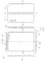
- FIG. 2A is a view illustrating a foldable housing of an electronic device, which is in a flat state, according to an embodiment.
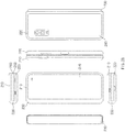
- FIG. 2B is a view illustrating a foldable housing of an electronic device, which is in a folded state, according to an embodiment.
- a foldable housing 200 may have a flat state or an unfolded state as illustrated in FIG. 2A , and may have a folded state and an intermediate state between the flat state and the folded state as illustrated in FIG. 2B .
- the "folded state” may refer to “fully folded state”
- the “intermediate state” may refer to that the electronic device is folded with a certain angle.
- the electronic device may include the foldable housing 200 and antenna radiators 240a and 240b.
- the foldable housing 200 may include a hinge structure 230, and a first housing structure 210 and a second housing structure 220 which are folded about the hinge structure 230.
- the first housing structure 210 which is coupled to the hinge structure 230, may include a first surface 250 facing a first direction and a second surface 270 facing a second direction opposite to the first direction.
- the second housing structure 220 which is coupled to the hinge structure 230, may include a third surface 260 facing a third direction and a fourth surface 280 facing a fourth direction opposite to the third direction.
- the electronic device may include a display (e.g., a flexible display or a foldable display).
- the display may be disposed on the first surface 250 of the first housing structure 210 and on the third surface 260 of the second housing structure 220.
- first housing structure 210 and the second housing structure 220 may disposed at opposite sides about a folding axis (axis "A") and may have a symmetrical shape about the folding axis A. As described later, the first housing structure 210 and the second housing structure 220 may have various angles or various distances formed therebetween, depending on whether the folding state of the foldable housing 200 is the unfolded state, the folded state, or the intermediate state.
- the first housing structure 210 and the second housing structure 220 may have an angle of 180 degrees therebetween and may be arranged to face the same direction.
- the first direction in which the first surface 250 of the first housing structure 210 faces may be the same as the third direction in which the third surface 260 of the second housing structure 220 faces.
- the first housing structure 210 and the second housing structure 220 may be arranged to face each other.
- the first surface 250 of the first housing structure 210 may face the third surface 260 of the second housing structure 220.
- the first housing structure 210 and the second housing structure 220 may be arranged with a certain angle.
- the first surface 250 of the first housing structure 210 and the third surface 260 of the second housing structure 220 may have an angle greater than an angle in the folded state and less than an angle in the unfolded state.
- the hinge structure 230 is interposed between the first housing structure 210 and the second housing structure 220 to couple the first housing structure 210 to the second housing structure 220 .
- the hinge structure 230 may be covered by a portion of the first housing structure 210 and the second housing structure 220 or be exposed to the outside, depending on the folding states of the foldable housing 200.
- the hinge structure 230 may be covered by the first housing structure 210 and the second housing structure 220 and not exposed to the outside.
- the hinge structure 230 may be exposed to the outside between the first housing structure 210 and the second housing structure 220.
- the exposed area of the hinge structure 230 may be smaller than the exposed area of the hinge structure 230 when the first housing structure 210 and the second housing structure 220 are in the fully folded state.
- the antenna radiators 240a and 240b may be included at least one of the first housing structure 210 or the second housing structure 220. According to an embodiment, the antenna radiators 240a and 240b may be included in a portion of at least one of a side surface member disposed perpendicularly to the first surface 250 or the second surface 270 of the first housing structure 210 or a side surface member disposed perpendicularly to the third surface 260 or the fourth surface 280 of the second housing structure 220.
- the antenna radiators 240a and 240b may be formed of a conductive material such as metal.
- the foldable housing 200 is not limited to the shapes illustrated in FIGS. 2A and 2B and the combination of the shapes and may be implemented in a different shape, through the combination of parts and/or the coupling of the parts.
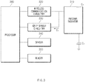
- FIG. 3 is a block diagram illustrating an electronic device, according to an embodiment.
- an electronic device may include an antenna radiator 310, a wireless communication circuitry 320, a grip sensor circuitry 330, a sensor 340, a memory 350, and a processor 360.
- the antenna radiator 310 may be implemented with a portion of the first housing structure 210 or the second housing structure 220.
- the antenna radiator 310 may be implemented with a portion of a side surface member of the first housing structure 210 or the second housing structure 220.
- the antenna radiator 310 may radiate a communication signal under the control of the wireless communication circuitry 320.
- the antenna radiator 310 may be an antenna having a conductive pattern
- the antenna radiator 310 may be a radiator resonating at a predetermined frequency band and having a feeding part (not illustrated) and a grounding part (not illustrated).
- the antenna radiator 310 may be electrically connected with the wireless communication circuitry 320.
- the antenna radiator 310 may be any one of a mobile communication antenna, a sub-communication antenna, a near field communication (NFC) antenna, a broadcasting communication antenna, a global positioning system (GPS) antenna, or a wireless charging antenna.
- a mobile communication antenna a sub-communication antenna
- NFC near field communication
- GPS global positioning system
- the wireless communication circuitry 320 may be disposed inside the first housing structure 210 or the second housing structure 220.
- the wireless communication circuitry 320 may make communication by transmitting/receiving a signal (e.g., communication signal) having a predetermined frequency band to/from an external device by using the antenna radiator 310.
- a signal e.g., communication signal
- the wireless communication circuitry 320 may control the intensity of a signal radiated through the antenna radiator 310 under the control of the processor 360.
- the grip sensor circuitry 330 may be disposed inside the first housing structure 210 or the second housing structure 220.
- the grip sensor circuitry 330 may be disposed adjacent to an outer surface of the first housing structure 210 or the second housing structure 220 to sense the grip of the user.
- signs "Cs", “Cf”, and “Cp” do not actually indicate capacitors, but refer to virtual capacitances for the explanation of an operating principle of the grip sensor circuitry 330.
- the grip sensor circuitry 330 may be electrically connected with a conductive pad (not illustrated) and may be connected with the ground of a printed circuit board (PCB).
- PCB printed circuit board
- the grip sensor circuitry 330 may measure the capacitance Cs corresponding to the sum of the capacitance Cp between the grip sensor circuitry 330 and the ground of the PCB, the capacitance of the antenna radiator 310, and the capacitance Cf between an external object and the conductive pad (not illustrated).
- the capacitance Cs may be varied depending on the extent that the external object approaches the antenna radiator 310.
- the capacitance Cs may become the capacitance Cp between the grip sensor circuitry 330 and the ground of the PCB, before the external object approaches the antenna radiator 310.
- the capacitance Cs becomes a value obtained by adding the capacitance Cf between the approaching external object and the conductive pad (not illustrated) to the capacitance Cp between the grip sensor circuitry 330 and the ground of the PCB.
- the sensor 340 may be disposed inside the first housing structure 210 or the second housing structure 220.
- the sensor 340 may include at least one of a geomagnetic sensor, an acceleration sensor, a hall sensor or a magnetic sensor, a bending sensor, a temperature/humidity sensor, an infrared sensor, a gyroscope sensor, a position sensor (e.g., GPS), an air pressure sensor, a proximity sensor, or an RGB sensor (illuminance sensor).
- the sensor 340 may sense the folding state of the foldable housing 200 For example, the sensor 340 may sense whether the foldable housing 200 is in the folded state, the flat state, and the intermediate state.
- the intermediate state may include a plurality of states.
- the angle formed between the first surface 250 of the first housing structure 210 and the third surface 260 of the second housing structure 220 may be in the range of 0 and 180 degrees.
- the intermediate state is a state where the angle formed between the first surface 250 and the third surface 260 is in the range of 0 to 30 degrees, 30 to 60 degrees, 60 to 90 degrees, 90 to 120 degrees, 120 to 150 degrees, and 150 to 180 degrees.
- the sensor 340 may sense the type of the folding state of the foldable housing 200 of the plurality of states.
- the senor 340 may measure an angle between the first surface 250 of the first housing structure 210 and the third surface 260 of the second housing structure 220 in the foldable housing 200.
- the sensor 340 may sense an unfolding motion or folding motion of the electronic device 101.
- the sensor 340 may detect a motion of the foldable housing 200 changed from the folded state to the unfolded state or changed from the unfolded state to the folded state.
- the sensor 340 measures an angle change resulting from a motion of the foldable housing 200 changed to the folded state or the unfolded state to detect the changed motion.
- the sensor 340 may sense the folding state or the unfolding state of the electronic device 101.
- the hall sensor 340 provided in the folded area measures a magnetic field to measure the distance between the first surface 250 of the first housing structure 210 and the third surface 260 of the second housing structure 220 in the foldable housing 200, thereby sensing whether the foldable housing 200 is in the folded state or the unfolded state.
- the senor 340 may provide, to the processor 360, at least one of the folding state of the foldable housing 200, the angle between the first surface 250 of the first housing structure 210 and the third surface 260 of the second housing structure 220, or the motion state of the foldable housing 200.
- the memory 350 may store a command, information, or data associated with the operations of components 310 to 340, and 360 included in the electronic device.
- the memory 350 may store instructions that, when executed, cause the processor 360 to perform the various operations described in the disclosure.
- the processor 360 may control the overall operation of the electronic devices according to various embodiments.
- the processor 360 may be disposed inside the first housing structure 210 or the second housing structure 220 and may be operatively coupled to the wireless communication circuitry 320, the sensor 340, and the grip sensor circuitry 330.
- the processor 360 may sense the folding state of the foldable housing 200 using the sensor 340.
- the processor 360 may calculate a reference capacitance for measuring the variation in the capacitance measured through the grip sensor circuitry 330.
- the processor 360 may control the wireless communication circuitry 320 such that the intensity of a signal radiated through the antenna radiator 310 is restricted to be equal to or less than a value resulting from the folding state of the foldable housing 200.
- the processor 360 may release the restriction of the intensity of the signal radiated through the antenna radiator 310.
- the electronic device of FIG. 3 performs the process of FIG. 4 .
- the operation described as being performed by the electronic device may be implemented by instructions that may be performed (or executed) by the processor 360 of the electronic device.
- the instructions may be stored, for example, in a computer recording medium or the memory 350 of the electronic device illustrated in FIG. 3 .
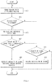
- FIG. 4 is a flowchart illustrating a method for controlling the intensity of a signal radiated, according to an embodiment.
- the processor 360 may sense the folding state of the foldable housing 200 by using the sensor 340.
- the processor 360 may sense the type of the folding state of the foldable housing 200 by using the sensor 340.
- the folding state may include a first state that the foldable housing 200 is folded and a second state that the foldable housing 200 is unfolded.
- the folding state may further include at least one third state which is intermediate between the first state that the foldable housing 200 is folded and the second state that the foldable housing 200 is unfolded.
- the third state may be the intermediate state described above.
- the folding state may include a plurality of third states.
- the plurality of third states may include a state that the angle formed between the first surface 250 of the first housing structure 210 and the third surface 260 of the second housing structure 220 is in the range of 0 to 30 degrees, 30 to 60 degrees, 60 to 90 degrees, 90 to 120 degrees, 120 to 150 degrees, and 150 to 180 degrees.
- the processor 360 may calculate a reference capacitance for measuring the variation in the capacitance measured through the grip sensor circuitry 330 in operation 405.
- the reference capacitance may be an average value of capacitances measured through the grip sensor circuitry 330 for a preset time, after the folding state of the foldable housing 200 is changed.
- the processor 360 may determine whether the variation in the capacitance, which is measured through the grip sensor circuitry 330, exceeds a specific threshold value.
- the variation in the capacitance may be a value obtained by subtracting the reference capacitance from the capacitance measured through the grip sensor circuitry 330.
- the measured capacitance is increased and the variation in the capacitance is increased.
- a preset threshold value may be varied depending on the folding state of the foldable housing 200.
- the threshold value when the folding state of the foldable housing 200 is sensed as the first state may be less than the threshold value when the folding state of the foldable housing 200 is sensed as the second state.
- the processor 360 may reduce the intensity of a signal radiated from the antenna radiator 310.
- the processor 360 may not reduce the intensity of the signal radiated through the antenna radiator 310.
- the processor 360 may control the wireless communication circuitry 320 to restrict the intensity of the signal radiated from the antenna radiator 310 to be equal to or less than a value resulting from the folding state of the foldable housing 200 in operation 409.
- the value resulting from the first state may be greater than the value resulting from the second state.
- the intensity of the signal radiated from the antenna radiator 310 may have a greater value, when the variation in the capacitance of the foldable housing 200 in the folded state exceeds the threshold value, as compared to when the variation in the capacitance of the foldable housing 200 in the unfolded state exceeds the threshold value.
- the value resulting from the third state may be less than the value resulting from the first state and may be greater than the value resulting from the second state.
- the intensity of a signal radiated from the antenna radiator 310 when the foldable housing 200 is in the intermediate state and the variation in the capacitance exceeds the threshold value may be less than the intensity of a signal radiated from the antenna radiator 310 when the foldable housing 200 is in the folded state and when the variation in the capacitance exceeds the threshold value, and may be greater than the intensity of a signal radiated from the antenna radiator 310 when the foldable housing 200 is in the unfolded state and when the variation in the capacitance exceeds the threshold value.
- a value from the plurality of third states may be reduced as the folding state approximates to the second state.
- the processor 360 may control the wireless communication circuitry 320 to restrict the intensity of the signal radiated from the antenna radiator 310 to be equal to or less than a value resulting from the folding state of the foldable housing 200 in operation 411.
- the processor 360 may release the restriction of the intensity of the signal radiated from the antenna radiator 310 in operation 413.
- the processor 360 may recover the intensity of the signal radiated from the antenna radiator 310.
- the processor 360 may calculate a reference capacitance when the folding state of the foldable housing 200 is changed (operation 403) and when the wireless communication circuitry 320 is controlled to restrict the intensity of the signal radiated from the antenna radiator 310 to be equal to or less than the value resulting from the folding state of the foldable housing 200 (operation 411).
- the processor 360 may release the restriction.
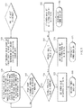
- FIG. 5 is a flowchart illustrating a method for controlling the intensity of a radiated signal through various manners by an electronic device 101, according to an embodiment.
- the electronic device 101 may determine whether the value of a hall integrated circuit (hall IC) is changed in operation 510.
- the hall IC value may be a digital value indicating the folding state of the foldable housing 200.
- the hall IC value may be calculated based on a measurement result of the sensor 340 implemented with a hall sensor.
- the hall IC value may have a value of '0' or '1'.
- the hall IC value when the foldable housing 200 is in the unfolded state, the hall IC value may be '0'.
- the hall IC value when the foldable housing 200 is in the folded state, the hall IC value may be '1'.
- the electronic device 101 may determine the folding state of the electronic device as being changed.
- the electronic device 101 may refresh the grip sensor circuitry 330 and reset sensor data of the sensor 340 in operation 520.
- the capacitance measured by the grip sensor circuitry 330 is changed. Accordingly, the value measured before the folding state is changed may be removed.
- the electronic device 101 may re-calculate a proximity offset value of the grip sensor circuitry 330.
- the electronic device 101 may a measured proximity average value.
- the electronic device 101 may set a threshold value based on the changed hall IC value in operation 520.
- the threshold value may be a value for changing the capacitance as much as possible in each folding state of the foldable housing 200.
- the electronic device 101 may calculate the variation in the capacitance measured by the grip sensor circuitry 330 and compare the variation with the threshold value in operation 530.
- the variation in the capacitance, which is measured by the grip sensor circuitry 330 may be a difference value between an effective capacitance and an average capacitance.
- the electronic device 101 may set a proximity state to a working state when the variation in the capacitance measured by the grip sensor circuitry 330 is greater than the threshold value in operation 530, and may set the proximity state to a release state when the variation in the capacitance is less than or equal to the threshold value.
- the electronic device 101 may determine whether the proximity state is changed in operation 540. When the proximity state is changed, the electronic device 101 may proceed to operation 550. When the proximity state is not changed, the electronic device 101 may return to operation 530.
- the electronic device 101 may determine whether the changed proximity state is the working state in operation 550. When that the variation in the capacitance is changed to a value in the working state, which is greater than the threshold value, the electronic device 101 may proceed to operation 565. When the variation in the capacitance is not changed to a value in the working state, the electronic device 101 may proceed to operation 555.
- the electronic device 101 may set the communication processor (e.g., the auxiliary processor 123 of FIG. 1 ) to output a power value, which is recovered from the communication processor, through a power amplifier (PA), in operation 555.
- the communication processor e.g., the auxiliary processor 123 of FIG. 1
- PA power amplifier
- the electronic device 101 may control the output power to return to a normal sate, in operation 560.
- the electronic device 101 may recover the output power by performing "power back off". Accordingly, when the variation in the capacitance is less than or equal to the threshold value, the electronic device 101 may maintain the normal output.
- the electronic device 101 may determine whether a present hall IC value is 1 in operation 565. The electronic device 101 may proceed to operation 570 when the present hall IC value is '1'. The electronic device may proceed to operation 580 when the present hall IC value is not '1'.
- the electronic device 101 may set the communication processor to output, through the PA, a power value, which is set to "power back off” in the communication processor.
- the "power back off” is set in the state that the foldable housing 200 is in a folder close (F/C) state or the folded state, in operation 570.
- the electronic device 101 may perform power back off in the F/C state in operation 575.
- the electronic device may restrict the maximum intensity of the signal radiated from the electronic device to a value corresponding to the threshold value set in the F/C state.
- the electronic device 101 may set the communication processor to output, through the PA, a power value set to "power back off", in the state that the foldable housing 200 is in a folder open (F/O) state, which is the unfolded state, in operation 580.
- a power value set to "power back off” in the state that the foldable housing 200 is in a folder open (F/O) state, which is the unfolded state, in operation 580.
- the electronic device 101 may perform power back off in the F/O state in operation 585.
- the electronic device 101 may restrict the maximum intensity of the signal radiated from the electronic device to a value corresponding to the threshold value set in the F/O state.
- the electronic device may be one of various types of electronic devices.
- the electronic devices may include, for example, a portable communication device (e.g., a smartphone), a computer device, a portable multimedia device, a portable medical device, a camera, a wearable device, or a home appliance. According to an embodiment of the disclosure, the electronic devices are not limited to those described above.
- each of such phrases as “A or B,” “at least one of A and B,” “at least one of A or B,” “A, B, or C,” “at least one of A, B, and C,” and “at least one of A, B, or C,” may include any one of, or all possible combinations of the items enumerated together in a corresponding one of the phrases.
- such terms as “1st” and “2nd,” or “first” and “second” may be used to simply distinguish a corresponding component from another, and does not limit the components in other aspect (e.g., importance or order).
- an element e.g., a first element
- the element may be coupled with the other element directly (e.g., wiredly), wirelessly, or via a third element.
- module may include a unit implemented in hardware, software, or firmware, and may interchangeably be used with other terms, for example, “logic,” “logic block,” “part,” or “circuitry”.
- a module may be a single integral component, or a minimum unit or part thereof, adapted to perform one or more functions.
- the module may be implemented in a form of an application-specific integrated circuit (ASIC).
- ASIC application-specific integrated circuit
- Various embodiments as set forth herein may be implemented as software (e.g., the program 140) including one or more instructions that are stored in a storage medium (e.g., internal memory 136 or external memory 138) that is readable by a machine (e.g., the electronic device 101).
- a processor(e.g., the processor 120) of the machine e.g., the electronic device 101
- the one or more instructions may include a code generated by a complier or a code executable by an interpreter.
- the machine-readable storage medium may be provided in the form of a non-transitory storage medium.
- non-transitory simply means that the storage medium is a tangible device, and does not include a signal (e.g., an electromagnetic wave), but this term does not differentiate between where data is semi-permanently stored in the storage medium and where the data is temporarily stored in the storage medium.
- a method may be included and provided in a computer program product.
- the computer program product may be traded as a product between a seller and a buyer.
- the computer program product may be distributed in the form of a machine-readable storage medium (e.g., compact disc read only memory (CD-ROM)), or be distributed (e.g., downloaded or uploaded) online via an application store (e.g., PlayStoreTM), or between two user devices (e.g., smart phones) directly. If distributed online, at least part of the computer program product may be temporarily generated or at least temporarily stored in the machine-readable storage medium, such as memory of the manufacturer's server, a server of the application store, or a relay server.
- CD-ROM compact disc read only memory
- an application store e.g., PlayStoreTM
- two user devices e.g., smart phones
- each component e.g., a module or a program of the above-described components may include a single entity or multiple entities. According to various embodiments, one or more of the above-described components may be omitted, or one or more other components may be added. Alternatively or additionally, a plurality of components (e.g., modules or programs) may be integrated into a single component. In such a case, according to various embodiments, the integrated component may still perform one or more functions of each of the plurality of components in the same or similar manner as they are performed by a corresponding one of the plurality of components before the integration.
- operations performed by the module, the program, or another component may be carried out sequentially, in parallel, repeatedly, or heuristically, or one or more of the operations may be executed in a different order or omitted, or one or more other operations may be added.
- the malfunction when the intensity of the signal radiated from the antenna radiator is controlled by the grip sensor, and when the foldable housing is folded, the malfunction may be prevented and the threshold value and the control power value may be set to different values depending on when the foldable housing is closed or open.
Landscapes
- Engineering & Computer Science (AREA)
- Computer Hardware Design (AREA)
- Theoretical Computer Science (AREA)
- General Engineering & Computer Science (AREA)
- Physics & Mathematics (AREA)
- General Physics & Mathematics (AREA)
- Human Computer Interaction (AREA)
- Signal Processing (AREA)
- Computer Networks & Wireless Communication (AREA)
- Mathematical Physics (AREA)
- Electromagnetism (AREA)
- Telephone Set Structure (AREA)
- Telephone Function (AREA)
Abstract
Description
- This application is based on and claims priority under 35 U.S.C. § 119 to Korean Patent Application No.
10-2018-0132604, filed on October 31, 2018 - The disclosure relates to an electronic device including a foldable housing.
- A specific absorption rate (SAR) is a numerical value of an amount of electromagnetic waves absorbed by a human body.
- To reduce the numerical value of the SAR, the intensity of an electromagnetic wave signal actually radiated from an antenna may be reduced by changing an antenna radiation pattern or reducing power supplied to the antenna.
- An antenna shape or a matching value is changed for the changing of the antenna radiation pattern, which exerts an influence on the whole performance of the antenna. In addition, in an electronic device using a metal frame as an antenna, the antenna radiation pattern may not be easily changed.
- Further, transmission power may be lowered to satisfy the SAR standard, which causes the whole antenna performance of a phone to be deteriorated.
- The above information is presented as background information only to assist with an understanding of the disclosure. No determination has been made, and no assertion is made, as to whether any of the above might be applicable as prior art with regard to the disclosure.
- When the foldable electronic device is folded, the capacitance measured by a grip sensor is increased as a metal part of a counterpart approaches. When the capacitance exceeds a threshold value, the electronic device may reduce power supplied to the antenna radiator, which causes performance to be deteriorated.
- In addition, the foldable electronic device has radiation performance different in the folding state and the unfolded state, which makes difference is made in the SAR value. Therefore, the antenna radiator may be set to be supplied with power different depending on folding states.
- Aspects of the disclosure are to address at least the above-mentioned problems and/or disadvantages and to provide at least the advantages described below. Accordingly, an aspect of the disclosure is to sense a folding state of an electronic device using a sensor and to control an antenna depending on the folding state.
- In accordance with another aspect of the disclosure, an electronic device may include a foldable housing including a hinge structure, a first housing structure coupled to the hinge structure and including a first surface facing a first direction and a second surface facing a second direction opposite to the first direction, a second housing structure coupled to the hinge structure, including a third surface facing a third direction and a fourth surface facing a fourth direction opposite to the third direction, and folded with respect to the first housing structure about the hinge structure, wherein the first surface faces the third surface when the foldable housing is folded, and the first direction is the same as the third direction when the foldable housing is unfolded, a wireless communication circuitry disposed inside the first housing structure or the second housing structure, an antenna radiator disposed inside the first housing structure or the second housing structure or exposed through at least one surface of the first housing structure or the second housing structure and electrically connected with the wireless communication circuitry, a sensor disposed inside the first housing structure or the second housing structure to sense a folding state of the foldable housing, a grip sensor circuitry disposed inside the first housing structure or the second housing structure or exposed through at least one surface of the first housing structure or the second housing structure, a processor disposed inside the first housing structure or the second housing structure and operatively connected with the wireless communication circuitry, the sensor, and the grip sensor circuitry, and a memory operatively connected with the processor. The memory may store instructions that when executed, cause the processor to sense the folding state of the foldable housing by using the sensor, calculate a reference capacitance for measuring a variation in a capacitance measured through the grip sensor circuitry, when the folding state of the foldable housing is changed, and control the wireless communication circuitry to restrict an intensity of a signal radiated from the antenna radiator to be equal to or less than a value resulting from the folding state of the foldable housing, when the variation in the capacitance measured through the grip sensor circuitry exceeds a preset threshold value.
- In accordance with another aspect of the disclosure, an electronic device may include a foldable housing including, a hinge structure, a first housing structure coupled to the hinge structure and including a first surface facing a first direction and a second surface facing a second direction opposite to the first direction, a second housing structure coupled to the hinge structure, including a third surface facing a third direction and a fourth surface facing a fourth direction opposite to the third direction, and folded with respect to the first housing structure about the hinge structure, wherein the first surface faces the third surface when the foldable housing is folded, and the first direction is the same as the third direction when the foldable housing is unfolded, a wireless communication circuitry disposed inside the first housing structure or the second housing structure, a sensor disposed inside the first housing structure or the second housing structure to sense a folding state of the foldable housing, a grip sensor circuitry disposed outside the first housing structure or the second housing structure, a processor disposed inside the first housing structure or the second housing structure and operatively connected with the wireless communication circuitry, the sensor, and the grip sensor circuitry, and a memory operatively connected with the processor. The memory may store instructions that when executed, cause the processor to control the grip sensor circuit, based at least on sensor data obtained from the sensor.
- In accordance with another aspect of the disclosure, in a computer-readable storage medium to store instructions, the instructions may cause, when executed by a processor of an electronic device including a foldable housing, the electronic device to sense a folding state of the foldable housing, to calculate a reference capacitance for measuring a variation in a capacitance measured through a grip sensor circuitry, when the folding state of the foldable housing is changed, and to restrict an intensity of a signal radiated from an antenna radiator to be equal to or less than a value resulting from the folding state of the foldable housing when the variation in the capacitance measured through the grip sensor circuitry exceeds a preset threshold value.
- Other aspects, advantages, and salient features of the disclosure will become apparent to those skilled in the art from the following detailed description, which, taken in conjunction with the annexed drawings, discloses various embodiments of the disclosure.
- Before undertaking the DETAILED DESCRIPTION below, it may be advantageous to set forth definitions of certain words and phrases used throughout this patent document: the terms "include" and "comprise," as well as derivatives thereof, mean inclusion without limitation; the term "or," is inclusive, meaning and/or; the phrases "associated with" and "associated therewith," as well as derivatives thereof, may mean to include, be included within, interconnect with, contain, be contained within, connect to or with, couple to or with, be communicable with, cooperate with, interleave, juxtapose, be proximate to, be bound to or with, have, have a property of, or the like; and the term "controller" means any device, system or part thereof that controls at least one operation, such a device may be implemented in hardware, firmware or software, or some combination of at least two of the same. It should be noted that the functionality associated with any particular controller may be centralized or distributed, whether locally or remotely.
- Moreover, various functions described below can be implemented or supported by one or more computer programs, each of which is formed from computer readable program code and embodied in a computer readable medium. The terms "application" and "program" refer to one or more computer programs, software components, sets of instructions, procedures, functions, objects, classes, instances, related data, or a portion thereof adapted for implementation in a suitable computer readable program code. The phrase "computer readable program code" includes any type of computer code, including source code, object code, and executable code. The phrase "computer readable medium" includes any type of medium capable of being accessed by a computer, such as read only memory (ROM), random access memory (RAM), a hard disk drive, a compact disc (CD), a digital video disc (DVD), or any other type of memory. A "non-transitory" computer readable medium excludes wired, wireless, optical, or other communication links that transport transitory electrical or other signals. A non-transitory computer readable medium includes media where data can be permanently stored and media where data can be stored and later overwritten, such as a rewritable optical disc or an erasable memory device.
- Definitions for certain words and phrases are provided throughout this patent document. Those of ordinary skill in the art should understand that in many, if not most instances, such definitions apply to prior, as well as future uses of such defined words and phrases.
- The above and other aspects, features, and advantages of certain embodiments of the disclosure will be more apparent from the following description taken in conjunction with the accompanying drawings, in which:
-
FIG. 1 is a block diagram illustrating an electronic device in a network environment according to various embodiments. -
FIG. 2A is a view illustrating a foldable housing of an electronic device, which is in a flat state, according to an embodiment; -
FIG. 2B is a view illustrating a foldable housing of an electronic device, which is in a folded state, according to an embodiment; -
FIG. 3 is a block diagram illustrating an electronic device, according to an embodiment; -
FIG. 4 is a flowchart illustrating a method for controlling the intensity of a radiated signal, according to an embodiment; and -
FIG. 5 is a flowchart illustrating a method for controlling the intensity of a radiated signal through various manners by an electronic device, according to an embodiment. - In the following description made with respect to the accompanying drawings, similar components will be assigned with similar reference numerals.
-
FIGS. 1 through 5 , discussed below, and the various embodiments used to describe the principles of the present disclosure in this patent document are by way of illustration only and should not be construed in any way to limit the scope of the disclosure. Those skilled in the art will understand that the principles of the present disclosure may be implemented in any suitably arranged system or device - Hereinafter, various embodiments of the disclosure may be described with reference to accompanying drawings. However, those of ordinary skill in the art will understand that the disclosure is not limited to a specific embodiment, and modifications, equivalents, and/or alternatives on the various embodiments described herein can be variously made without departing from the scope and spirit of the disclosure.
-
FIG. 1 is a block diagram illustrating anelectronic device 101 in anetwork environment 100 according to various embodiments. Referring toFIG. 1 , theelectronic device 101 in thenetwork environment 100 may communicate with anelectronic device 102 via a first network 198 (e.g., a short-range wireless communication network), or anelectronic device 104 or aserver 108 via a second network 199 (e.g., a long-range wireless communication network). According to an embodiment, theelectronic device 101 may communicate with theelectronic device 104 via theserver 108. According to an embodiment, theelectronic device 101 may include aprocessor 120,memory 130, aninput device 150, asound output device 155, adisplay device 160, anaudio module 170, asensor module 176, aninterface 177, ahaptic module 179, acamera module 180, apower management module 188, abattery 189, acommunication module 190, a subscriber identification module (SIM) 196, or anantenna module 197. In some embodiments, at least one (e.g., thedisplay device 160 or the camera module 180) of the components may be omitted from theelectronic device 101, or one or more other components may be added in theelectronic device 101. In some embodiments, some of the components may be implemented as single integrated circuitry. For example, the sensor module 176 (e.g., a fingerprint sensor, an iris sensor, or an illuminance sensor) may be implemented as embedded in the display device 160 (e.g., a display). - The
processor 120 may execute, for example, software (e.g., a program 140) to control at least one other component (e.g., a hardware or software component) of theelectronic device 101 coupled with theprocessor 120, and may perform various data processing or computation. According to one embodiment, as at least part of the data processing or computation, theprocessor 120 may load a command or data received from another component (e.g., thesensor module 176 or the communication module 190) involatile memory 132, process the command or the data stored in thevolatile memory 132, and store resulting data innon-volatile memory 134. According to an embodiment, theprocessor 120 may include a main processor 121 (e.g., a central processing unit (CPU) or an application processor (AP)), and an auxiliary processor 123 (e.g., a graphics processing unit (GPU), an image signal processor (ISP), a sensor hub processor, or a communication processor (CP)) that is operable independently from, or in conjunction with, themain processor 121. Additionally or alternatively, theauxiliary processor 123 may be adapted to consume less power than themain processor 121, or to be specific to a specified function. Theauxiliary processor 123 may be implemented as separate from, or as part of themain processor 121. - The
auxiliary processor 123 may control at least some of functions or states related to at least one component (e.g., thedisplay device 160, thesensor module 176, or the communication module 190) among the components of theelectronic device 101, instead of themain processor 121 while themain processor 121 is in an inactive (e.g., sleep) state, or together with themain processor 121 while themain processor 121 is in an active state (e.g., executing an application). According to an embodiment, the auxiliary processor 123 (e.g., an image signal processor or a communication processor) may be implemented as part of another component (e.g., thecamera module 180 or the communication module 190) functionally related to theauxiliary processor 123. - The
memory 130 may store various data used by at least one component (e.g., theprocessor 120 or the sensor module 176) of theelectronic device 101. The various data may include, for example, software (e.g., the program 140) and input data or output data for a command related thereto. Thememory 130 may include thevolatile memory 132 or thenon-volatile memory 134. - The
program 140 may be stored in thememory 130 as software, and may include, for example, an operating system (OS) 142,middleware 144, or anapplication 146. - The
input device 150 may receive a command or data to be used by other component (e.g., the processor 120) of theelectronic device 101, from the outside (e.g., a user) of theelectronic device 101. Theinput device 150 may include, for example, a microphone, a mouse, a keyboard, or a digital pen (e.g., a stylus pen). - The
sound output device 155 may output sound signals to the outside of theelectronic device 101. Thesound output device 155 may include, for example, a speaker or a receiver. The speaker may be used for general purposes, such as playing multimedia or playing record, and the receiver may be used for an incoming calls. According to an embodiment, the receiver may be implemented as separate from, or as part of the speaker. - The
display device 160 may visually provide information to the outside (e.g., a user) of theelectronic device 101. Thedisplay device 160 may include, for example, a display, a hologram device, or a projector and control circuitry to control a corresponding one of the display, hologram device, and projector. According to an embodiment, thedisplay device 160 may include touch circuitry adapted to detect a touch, or sensor circuitry (e.g., a pressure sensor) adapted to measure the intensity of force incurred by the touch. - The
audio module 170 may convert a sound into an electrical signal and vice versa. According to an embodiment, theaudio module 170 may obtain the sound via theinput device 150, or output the sound via thesound output device 155 or a headphone of an external electronic device (e.g., an electronic device 102) directly (e.g., wiredly) or wirelessly coupled with theelectronic device 101. - The
sensor module 176 may detect an operational state (e.g., power or temperature) of theelectronic device 101 or an environmental state (e.g., a state of a user) external to theelectronic device 101, and then generate an electrical signal or data value corresponding to the detected state. According to an embodiment, thesensor module 176 may include, for example, a gesture sensor, a gyro sensor, an atmospheric pressure sensor, a magnetic sensor, an acceleration sensor, a grip sensor, a proximity sensor, a color sensor, an infrared (IR) sensor, a biometric sensor, a temperature sensor, a humidity sensor, or an illuminance sensor. - The
interface 177 may support one or more specified protocols to be used for theelectronic device 101 to be coupled with the external electronic device (e.g., the electronic device 102) directly (e.g., wiredly) or wirelessly. According to an embodiment, theinterface 177 may include, for example, a high definition multimedia interface (HDMI), a universal serial bus (USB) interface, a secure digital (SD) card interface, or an audio interface. - A connecting
terminal 178 may include a connector via which theelectronic device 101 may be physically connected with the external electronic device (e.g., the electronic device 102). According to an embodiment, the connectingterminal 178 may include, for example, a HDMI connector, a USB connector, a SD card connector, or an audio connector (e.g., a headphone connector). - The
haptic module 179 may convert an electrical signal into a mechanical stimulus (e.g., a vibration or a movement) or electrical stimulus which may be recognized by a user via his tactile sensation or kinesthetic sensation. According to an embodiment, thehaptic module 179 may include, for example, a motor, a piezoelectric element, or an electric stimulator. - The
camera module 180 may capture a still image or moving images. According to an embodiment, thecamera module 180 may include one or more lenses, image sensors, image signal processors, or flashes. - The
power management module 188 may manage power supplied to theelectronic device 101. According to one embodiment, thepower management module 188 may be implemented as at least part of, for example, a power management integrated circuit (PMIC). - The
battery 189 may supply power to at least one component of theelectronic device 101. According to an embodiment, thebattery 189 may include, for example, a primary cell which is not rechargeable, a secondary cell which is rechargeable, or a fuel cell. - The
communication module 190 may support establishing a direct (e.g., wired) communication channel or a wireless communication channel between theelectronic device 101 and the external electronic device (e.g., theelectronic device 102, theelectronic device 104, or the server 108) and performing communication via the established communication channel. Thecommunication module 190 may include one or more communication processors that are operable independently from the processor 120 (e.g., the application processor (AP)) and supports a direct (e.g., wired) communication or a wireless communication. According to an embodiment, thecommunication module 190 may include a wireless communication module 192 (e.g., a cellular communication module, a short-range wireless communication module, or a global navigation satellite system (GNSS) communication module) or a wired communication module 194 (e.g., a local area network (LAN) communication module or a power line communication (PLC) module). A corresponding one of these communication modules may communicate with the external electronic device via the first network 198 (e.g., a short-range communication network, such as Bluetooth™, wireless-fidelity (Wi-Fi) direct, or infrared data association (IrDA)) or the second network 199 (e.g., a long-range communication network, such as a cellular network, the Internet, or a computer network (e.g., LAN or wide area network (WAN)). These various types of communication modules may be implemented as a single component (e.g., a single chip), or may be implemented as multi components (e.g., multi chips) separate from each other. Thewireless communication module 192 may identify and authenticate theelectronic device 101 in a communication network, such as thefirst network 198 or thesecond network 199, using subscriber information (e.g., international mobile subscriber identity (IMSI)) stored in thesubscriber identification module 196. - The
antenna module 197 may transmit or receive a signal or power to or from the outside (e.g., the external electronic device) of theelectronic device 101. According to an embodiment, theantenna module 197 may include an antenna including a radiating element composed of a conductive material or a conductive pattern formed in or on a substrate (e.g., PCB). According to an embodiment, theantenna module 197 may include a plurality of antennas. In such a case, at least one antenna appropriate for a communication scheme used in the communication network, such as thefirst network 198 or thesecond network 199, may be selected, for example, by the communication module 190 (e.g., the wireless communication module 192) from the plurality of antennas. The signal or the power may then be transmitted or received between thecommunication module 190 and the external electronic device via the selected at least one antenna. According to an embodiment, another component (e.g., a radio frequency integrated circuit (RFIC)) other than the radiating element may be additionally formed as part of theantenna module 197. - At least some of the above-described components may be coupled mutually and communicate signals (e.g., commands or data) therebetween via an inter-peripheral communication scheme (e.g., a bus, general purpose input and output (GPIO), serial peripheral interface (SPI), or mobile industry processor interface (MIPI)).
- According to an embodiment, commands or data may be transmitted or received between the
electronic device 101 and the externalelectronic device 104 via theserver 108 coupled with thesecond network 199. Each of theelectronic devices electronic device 101. According to an embodiment, all or some of operations to be executed at theelectronic device 101 may be executed at one or more of the externalelectronic devices electronic device 101 should perform a function or a service automatically, or in response to a request from a user or another device, theelectronic device 101, instead of, or in addition to, executing the function or the service, may request the one or more external electronic devices to perform at least part of the function or the service. The one or more external electronic devices receiving the request may perform the at least part of the function or the service requested, or an additional function or an additional service related to the request, and transfer an outcome of the performing to theelectronic device 101. Theelectronic device 101 may provide the outcome, with or without further processing of the outcome, as at least part of a reply to the request. To that end, a cloud computing, distributed computing, or client-server computing technology may be used, for example. -
FIG. 2A is a view illustrating a foldable housing of an electronic device, which is in a flat state, according to an embodiment.FIG. 2B is a view illustrating a foldable housing of an electronic device, which is in a folded state, according to an embodiment. - In an embodiment, a
foldable housing 200 may have a flat state or an unfolded state as illustrated inFIG. 2A , and may have a folded state and an intermediate state between the flat state and the folded state as illustrated inFIG. 2B . In the disclosure, unless otherwise specified, the "folded state" may refer to "fully folded state", and the "intermediate state" may refer to that the electronic device is folded with a certain angle. - Referring to
FIGS. 2A and2B , in an embodiment, the electronic device may include thefoldable housing 200 andantenna radiators foldable housing 200 may include ahinge structure 230, and afirst housing structure 210 and asecond housing structure 220 which are folded about thehinge structure 230. - The
first housing structure 210, which is coupled to thehinge structure 230, may include afirst surface 250 facing a first direction and asecond surface 270 facing a second direction opposite to the first direction. Thesecond housing structure 220, which is coupled to thehinge structure 230, may include athird surface 260 facing a third direction and afourth surface 280 facing a fourth direction opposite to the third direction. - According to an embodiment, the electronic device may include a display (e.g., a flexible display or a foldable display). The display may be disposed on the
first surface 250 of thefirst housing structure 210 and on thethird surface 260 of thesecond housing structure 220. - In the illustrated embodiment, the
first housing structure 210 and thesecond housing structure 220 may disposed at opposite sides about a folding axis (axis "A") and may have a symmetrical shape about the folding axis A. As described later, thefirst housing structure 210 and thesecond housing structure 220 may have various angles or various distances formed therebetween, depending on whether the folding state of thefoldable housing 200 is the unfolded state, the folded state, or the intermediate state. - In an embodiment, when the folding state of the
foldable housing 200 is the unfolded state (e.g., seeFIG. 2A ), thefirst housing structure 210 and thesecond housing structure 220 may have an angle of 180 degrees therebetween and may be arranged to face the same direction. In other words, the first direction in which thefirst surface 250 of thefirst housing structure 210 faces may be the same as the third direction in which thethird surface 260 of thesecond housing structure 220 faces. - In an embodiment, when the
foldable housing 200 is in the folded state (e.g., seeFIG. 2B ), thefirst housing structure 210 and thesecond housing structure 220 may be arranged to face each other. In other words, thefirst surface 250 of thefirst housing structure 210 may face thethird surface 260 of thesecond housing structure 220. - In an embodiment, when the folding state of the
foldable housing 200 is the intermediate state, thefirst housing structure 210 and thesecond housing structure 220 may be arranged with a certain angle. Thefirst surface 250 of thefirst housing structure 210 and thethird surface 260 of thesecond housing structure 220 may have an angle greater than an angle in the folded state and less than an angle in the unfolded state. - Referring to
FIG. 2B , thehinge structure 230 is interposed between thefirst housing structure 210 and thesecond housing structure 220 to couple thefirst housing structure 210 to thesecond housing structure 220 . - In an embodiment, the
hinge structure 230 may be covered by a portion of thefirst housing structure 210 and thesecond housing structure 220 or be exposed to the outside, depending on the folding states of thefoldable housing 200. - For example, when the
foldable housing 200 is in the flat state as illustrated inFIG. 2A , thehinge structure 230 may be covered by thefirst housing structure 210 and thesecond housing structure 220 and not exposed to the outside. For example, when thefoldable housing 200 is in the folded state (e.g., fully folded state) as illustrated inFIG. 2B , thehinge structure 230 may be exposed to the outside between thefirst housing structure 210 and thesecond housing structure 220. For example, when thefirst housing structure 210 and thesecond housing structure 220 are in the intermediate state that thefirst housing structure 210 and thesecond housing structure 220 are folded with a certain angle, a portion of thehinge structure 230 may be exposed to the outside between thefirst housing structure 210 and thesecond housing structure 220. However, in this embodiment, the exposed area of thehinge structure 230 may be smaller than the exposed area of thehinge structure 230 when thefirst housing structure 210 and thesecond housing structure 220 are in the fully folded state. - The
antenna radiators first housing structure 210 or thesecond housing structure 220. According to an embodiment, theantenna radiators first surface 250 or thesecond surface 270 of thefirst housing structure 210 or a side surface member disposed perpendicularly to thethird surface 260 or thefourth surface 280 of thesecond housing structure 220. Theantenna radiators - The
foldable housing 200 is not limited to the shapes illustrated inFIGS. 2A and2B and the combination of the shapes and may be implemented in a different shape, through the combination of parts and/or the coupling of the parts. -
FIG. 3 is a block diagram illustrating an electronic device, according to an embodiment. - Referring to
FIG. 3 , an electronic device may include anantenna radiator 310, awireless communication circuitry 320, agrip sensor circuitry 330, asensor 340, amemory 350, and aprocessor 360. - The
antenna radiator 310 may be implemented with a portion of thefirst housing structure 210 or thesecond housing structure 220. For example, theantenna radiator 310 may be implemented with a portion of a side surface member of thefirst housing structure 210 or thesecond housing structure 220. Theantenna radiator 310 may radiate a communication signal under the control of thewireless communication circuitry 320. Theantenna radiator 310 may be an antenna having a conductive pattern Theantenna radiator 310 may be a radiator resonating at a predetermined frequency band and having a feeding part (not illustrated) and a grounding part (not illustrated). Theantenna radiator 310 may be electrically connected with thewireless communication circuitry 320. - According to an embodiment, the
antenna radiator 310 may be any one of a mobile communication antenna, a sub-communication antenna, a near field communication (NFC) antenna, a broadcasting communication antenna, a global positioning system (GPS) antenna, or a wireless charging antenna. - The
wireless communication circuitry 320 may be disposed inside thefirst housing structure 210 or thesecond housing structure 220. Thewireless communication circuitry 320 may make communication by transmitting/receiving a signal (e.g., communication signal) having a predetermined frequency band to/from an external device by using theantenna radiator 310. - The
wireless communication circuitry 320 may control the intensity of a signal radiated through theantenna radiator 310 under the control of theprocessor 360. - The
grip sensor circuitry 330 may be disposed inside thefirst housing structure 210 or thesecond housing structure 220. For example, thegrip sensor circuitry 330 may be disposed adjacent to an outer surface of thefirst housing structure 210 or thesecond housing structure 220 to sense the grip of the user. InFIG. 3 , signs "Cs", "Cf", and "Cp" do not actually indicate capacitors, but refer to virtual capacitances for the explanation of an operating principle of thegrip sensor circuitry 330. Thegrip sensor circuitry 330 may be electrically connected with a conductive pad (not illustrated) and may be connected with the ground of a printed circuit board (PCB). Thegrip sensor circuitry 330 may measure the capacitance Cs corresponding to the sum of the capacitance Cp between thegrip sensor circuitry 330 and the ground of the PCB, the capacitance of theantenna radiator 310, and the capacitance Cf between an external object and the conductive pad (not illustrated). When the external object (e.g., a human body or an object except the human body) approaches theantenna radiator 310, the capacitance Cs may be varied depending on the extent that the external object approaches theantenna radiator 310. - For example, the capacitance Cs may become the capacitance Cp between the
grip sensor circuitry 330 and the ground of the PCB, before the external object approaches theantenna radiator 310. When the external object approaches theantenna radiator 310, the capacitance Cs becomes a value obtained by adding the capacitance Cf between the approaching external object and the conductive pad (not illustrated) to the capacitance Cp between thegrip sensor circuitry 330 and the ground of the PCB. - The
sensor 340 may be disposed inside thefirst housing structure 210 or thesecond housing structure 220. - For example, the
sensor 340 may include at least one of a geomagnetic sensor, an acceleration sensor, a hall sensor or a magnetic sensor, a bending sensor, a temperature/humidity sensor, an infrared sensor, a gyroscope sensor, a position sensor (e.g., GPS), an air pressure sensor, a proximity sensor, or an RGB sensor (illuminance sensor). - According to an embodiment, the
sensor 340 may sense the folding state of thefoldable housing 200 For example, thesensor 340 may sense whether thefoldable housing 200 is in the folded state, the flat state, and the intermediate state. - According to an embodiment, the intermediate state may include a plurality of states. For example, the angle formed between the
first surface 250 of thefirst housing structure 210 and thethird surface 260 of thesecond housing structure 220 may be in the range of 0 and 180 degrees. In an embodiment, the intermediate state is a state where the angle formed between thefirst surface 250 and thethird surface 260 is in the range of 0 to 30 degrees, 30 to 60 degrees, 60 to 90 degrees, 90 to 120 degrees, 120 to 150 degrees, and 150 to 180 degrees. Thesensor 340 may sense the type of the folding state of thefoldable housing 200 of the plurality of states. - According to an embodiment, the
sensor 340 may measure an angle between thefirst surface 250 of thefirst housing structure 210 and thethird surface 260 of thesecond housing structure 220 in thefoldable housing 200. - According to an embodiment, the
sensor 340 may sense an unfolding motion or folding motion of theelectronic device 101. According to an embodiment, thesensor 340 may detect a motion of thefoldable housing 200 changed from the folded state to the unfolded state or changed from the unfolded state to the folded state. For example, when thesensor 340 is implemented with a gyro sensor, thesensor 340 measures an angle change resulting from a motion of thefoldable housing 200 changed to the folded state or the unfolded state to detect the changed motion. For another example, thesensor 340 may sense the folding state or the unfolding state of theelectronic device 101. In detail, thehall sensor 340 provided in the folded area measures a magnetic field to measure the distance between thefirst surface 250 of thefirst housing structure 210 and thethird surface 260 of thesecond housing structure 220 in thefoldable housing 200, thereby sensing whether thefoldable housing 200 is in the folded state or the unfolded state. - In an embodiment, the
sensor 340 may provide, to theprocessor 360, at least one of the folding state of thefoldable housing 200, the angle between thefirst surface 250 of thefirst housing structure 210 and thethird surface 260 of thesecond housing structure 220, or the motion state of thefoldable housing 200. - The
memory 350 may store a command, information, or data associated with the operations ofcomponents 310 to 340, and 360 included in the electronic device. For example, thememory 350 may store instructions that, when executed, cause theprocessor 360 to perform the various operations described in the disclosure. - The
processor 360 may control the overall operation of the electronic devices according to various embodiments. Theprocessor 360 may be disposed inside thefirst housing structure 210 or thesecond housing structure 220 and may be operatively coupled to thewireless communication circuitry 320, thesensor 340, and thegrip sensor circuitry 330. - The
processor 360 may sense the folding state of thefoldable housing 200 using thesensor 340. Theprocessor 360 may calculate a reference capacitance for measuring the variation in the capacitance measured through thegrip sensor circuitry 330. Theprocessor 360 may control thewireless communication circuitry 320 such that the intensity of a signal radiated through theantenna radiator 310 is restricted to be equal to or less than a value resulting from the folding state of thefoldable housing 200. Theprocessor 360 may release the restriction of the intensity of the signal radiated through theantenna radiator 310. - In the following description, it is assumed that the electronic device of
FIG. 3 performs the process ofFIG. 4 . The operation described as being performed by the electronic device may be implemented by instructions that may be performed (or executed) by theprocessor 360 of the electronic device. The instructions may be stored, for example, in a computer recording medium or thememory 350 of the electronic device illustrated inFIG. 3 . -
FIG. 4 is a flowchart illustrating a method for controlling the intensity of a signal radiated, according to an embodiment. - In
operation 401, theprocessor 360 may sense the folding state of thefoldable housing 200 by using thesensor 340. - The
processor 360 may sense the type of the folding state of thefoldable housing 200 by using thesensor 340. - According to an embodiment, the folding state may include a first state that the
foldable housing 200 is folded and a second state that thefoldable housing 200 is unfolded. - According to an embodiment, the folding state may further include at least one third state which is intermediate between the first state that the
foldable housing 200 is folded and the second state that thefoldable housing 200 is unfolded. In other words, the third state may be the intermediate state described above. - According to an embodiment, the folding state may include a plurality of third states. For example, the plurality of third states may include a state that the angle formed between the
first surface 250 of thefirst housing structure 210 and thethird surface 260 of thesecond housing structure 220 is in the range of 0 to 30 degrees, 30 to 60 degrees, 60 to 90 degrees, 90 to 120 degrees, 120 to 150 degrees, and 150 to 180 degrees. - When the folding state of the
foldable housing 200 is changed (operation 403), theprocessor 360 may calculate a reference capacitance for measuring the variation in the capacitance measured through thegrip sensor circuitry 330 inoperation 405. - According to an embodiment, the reference capacitance may be an average value of capacitances measured through the
grip sensor circuitry 330 for a preset time, after the folding state of thefoldable housing 200 is changed. - In
operation 407, theprocessor 360 may determine whether the variation in the capacitance, which is measured through thegrip sensor circuitry 330, exceeds a specific threshold value. - According to an embodiment, the variation in the capacitance may be a value obtained by subtracting the reference capacitance from the capacitance measured through the
grip sensor circuitry 330. In an embodiment, when an external object approaches theantenna radiator 310, the measured capacitance is increased and the variation in the capacitance is increased. - According to an embodiment, a preset threshold value may be varied depending on the folding state of the
foldable housing 200. The threshold value when the folding state of thefoldable housing 200 is sensed as the first state may be less than the threshold value when the folding state of thefoldable housing 200 is sensed as the second state. - For example, when the
foldable housing 200 is in the folded state and the distance between the external object and theantenna radiator 310 is 10 mm, theprocessor 360 may reduce the intensity of a signal radiated from theantenna radiator 310. When thefoldable housing 200 is in the unfolded state and the distance between the external object and theantenna radiator 310 is 10 mm, theprocessor 360 may not reduce the intensity of the signal radiated through theantenna radiator 310. - When the variation in the capacitance measured through the
grip sensor circuitry 330 exceeds a preset threshold value (operation 407), theprocessor 360 may control thewireless communication circuitry 320 to restrict the intensity of the signal radiated from theantenna radiator 310 to be equal to or less than a value resulting from the folding state of thefoldable housing 200 inoperation 409. - According to an embodiment, the value resulting from the first state may be greater than the value resulting from the second state. In other words, the intensity of the signal radiated from the
antenna radiator 310 may have a greater value, when the variation in the capacitance of thefoldable housing 200 in the folded state exceeds the threshold value, as compared to when the variation in the capacitance of thefoldable housing 200 in the unfolded state exceeds the threshold value. - According to an embodiment, the value resulting from the third state may be less than the value resulting from the first state and may be greater than the value resulting from the second state.
- In other words, the intensity of a signal radiated from the
antenna radiator 310 when thefoldable housing 200 is in the intermediate state and the variation in the capacitance exceeds the threshold value, may be less than the intensity of a signal radiated from theantenna radiator 310 when thefoldable housing 200 is in the folded state and when the variation in the capacitance exceeds the threshold value, and may be greater than the intensity of a signal radiated from theantenna radiator 310 when thefoldable housing 200 is in the unfolded state and when the variation in the capacitance exceeds the threshold value. - According to an embodiment, when a plurality of third states are included, a value from the plurality of third states may be reduced as the folding state approximates to the second state.
- When the variation in the capacitance measured through the
grip sensor circuitry 330 is less than or equal to a preset threshold value (operation 407), theprocessor 360 may control thewireless communication circuitry 320 to restrict the intensity of the signal radiated from theantenna radiator 310 to be equal to or less than a value resulting from the folding state of thefoldable housing 200 inoperation 411. - When the intensity of the signal radiated from the
antenna radiator 310 is restricted to be equal to or less than the value resulting from the folding state of thefoldable housing 200, theprocessor 360 may release the restriction of the intensity of the signal radiated from theantenna radiator 310 inoperation 413. - The
processor 360 may recover the intensity of the signal radiated from theantenna radiator 310. - The
processor 360 may calculate a reference capacitance when the folding state of thefoldable housing 200 is changed (operation 403) and when thewireless communication circuitry 320 is controlled to restrict the intensity of the signal radiated from theantenna radiator 310 to be equal to or less than the value resulting from the folding state of the foldable housing 200 (operation 411). When the variation in the capacitance measured through thegrip sensor circuitry 330 does not exceed the preset threshold value (operation 407), theprocessor 360 may release the restriction. -
FIG. 5 is a flowchart illustrating a method for controlling the intensity of a radiated signal through various manners by anelectronic device 101, according to an embodiment. - According to an embodiment, the
electronic device 101 may determine whether the value of a hall integrated circuit (hall IC) is changed inoperation 510. The hall IC value may be a digital value indicating the folding state of thefoldable housing 200. The hall IC value may be calculated based on a measurement result of thesensor 340 implemented with a hall sensor. - According to an embodiment, the hall IC value may have a value of '0' or '1'. For example, when the
foldable housing 200 is in the unfolded state, the hall IC value may be '0'. For example, when thefoldable housing 200 is in the folded state, the hall IC value may be '1'. When the hall IC value is changed from '0' to '1' or from '1' to '0', theelectronic device 101 may determine the folding state of the electronic device as being changed. - According to an embodiment, the
electronic device 101 may refresh thegrip sensor circuitry 330 and reset sensor data of thesensor 340 inoperation 520. When the folding state of thefoldable housing 200 is changed, the capacitance measured by thegrip sensor circuitry 330 is changed. Accordingly, the value measured before the folding state is changed may be removed. For example, when the folding state is changed, theelectronic device 101 may re-calculate a proximity offset value of thegrip sensor circuitry 330. For another example, when the folding state is changed, theelectronic device 101 may a measured proximity average value. - In an embodiment, the
electronic device 101 may set a threshold value based on the changed hall IC value inoperation 520. The threshold value may be a value for changing the capacitance as much as possible in each folding state of thefoldable housing 200. - According to an embodiment, the
electronic device 101 may calculate the variation in the capacitance measured by thegrip sensor circuitry 330 and compare the variation with the threshold value inoperation 530. The variation in the capacitance, which is measured by thegrip sensor circuitry 330, may be a difference value between an effective capacitance and an average capacitance. - According to an embodiment, the
electronic device 101 may set a proximity state to a working state when the variation in the capacitance measured by thegrip sensor circuitry 330 is greater than the threshold value inoperation 530, and may set the proximity state to a release state when the variation in the capacitance is less than or equal to the threshold value. - According to an embodiment, the
electronic device 101 may determine whether the proximity state is changed inoperation 540. When the proximity state is changed, theelectronic device 101 may proceed tooperation 550. When the proximity state is not changed, theelectronic device 101 may return tooperation 530. - According to an embodiment, the
electronic device 101 may determine whether the changed proximity state is the working state inoperation 550. When that the variation in the capacitance is changed to a value in the working state, which is greater than the threshold value, theelectronic device 101 may proceed tooperation 565. When the variation in the capacitance is not changed to a value in the working state, theelectronic device 101 may proceed tooperation 555. - According to an embodiment, the
electronic device 101 may set the communication processor (e.g., theauxiliary processor 123 ofFIG. 1 ) to output a power value, which is recovered from the communication processor, through a power amplifier (PA), inoperation 555. - According to an embodiment, the
electronic device 101 may control the output power to return to a normal sate, inoperation 560. For example, theelectronic device 101 may recover the output power by performing "power back off". Accordingly, when the variation in the capacitance is less than or equal to the threshold value, theelectronic device 101 may maintain the normal output. - According to an embodiment, the
electronic device 101 may determine whether a present hall IC value is 1 inoperation 565. Theelectronic device 101 may proceed tooperation 570 when the present hall IC value is '1'. The electronic device may proceed tooperation 580 when the present hall IC value is not '1'. - According to an embodiment, the
electronic device 101 may set the communication processor to output, through the PA, a power value, which is set to "power back off" in the communication processor. The "power back off" is set in the state that thefoldable housing 200 is in a folder close (F/C) state or the folded state, inoperation 570. - According to an embodiment, the
electronic device 101 may perform power back off in the F/C state inoperation 575. The electronic device may restrict the maximum intensity of the signal radiated from the electronic device to a value corresponding to the threshold value set in the F/C state. - According to an embodiment, the
electronic device 101 may set the communication processor to output, through the PA, a power value set to "power back off", in the state that thefoldable housing 200 is in a folder open (F/O) state, which is the unfolded state, inoperation 580. - According to an embodiment, the
electronic device 101 may perform power back off in the F/O state inoperation 585. Theelectronic device 101 may restrict the maximum intensity of the signal radiated from the electronic device to a value corresponding to the threshold value set in the F/O state. - The electronic device according to various embodiments may be one of various types of electronic devices. The electronic devices may include, for example, a portable communication device (e.g., a smartphone), a computer device, a portable multimedia device, a portable medical device, a camera, a wearable device, or a home appliance. According to an embodiment of the disclosure, the electronic devices are not limited to those described above.
- It should be appreciated that various embodiments of the disclosure and the terms used therein are not intended to limit the technological features set forth herein to particular embodiments and include various changes, equivalents, or replacements for a corresponding embodiment. With regard to the description of the drawings, similar reference numerals may be used to refer to similar or related elements. It is to be understood that a singular form of a noun corresponding to an item may include one or more of the things, unless the relevant context clearly indicates otherwise. As used herein, each of such phrases as "A or B," "at least one of A and B," "at least one of A or B," "A, B, or C," "at least one of A, B, and C," and "at least one of A, B, or C," may include any one of, or all possible combinations of the items enumerated together in a corresponding one of the phrases. As used herein, such terms as "1st" and "2nd," or "first" and "second" may be used to simply distinguish a corresponding component from another, and does not limit the components in other aspect (e.g., importance or order). It is to be understood that if an element (e.g., a first element) is referred to, with or without the term "operatively" or "communicatively", as "coupled with," "coupled to," "connected with," or "connected to" another element (e.g., a second element), it means that the element may be coupled with the other element directly (e.g., wiredly), wirelessly, or via a third element.
- As used herein, the term "module" may include a unit implemented in hardware, software, or firmware, and may interchangeably be used with other terms, for example, "logic," "logic block," "part," or "circuitry". A module may be a single integral component, or a minimum unit or part thereof, adapted to perform one or more functions. For example, according to an embodiment, the module may be implemented in a form of an application-specific integrated circuit (ASIC).
- Various embodiments as set forth herein may be implemented as software (e.g., the program 140) including one or more instructions that are stored in a storage medium (e.g.,
internal memory 136 or external memory 138) that is readable by a machine (e.g., the electronic device 101). For example, a processor(e.g., the processor 120) of the machine (e.g., the electronic device 101) may invoke at least one of the one or more instructions stored in the storage medium, and execute it, with or without using one or more other components under the control of the processor. This allows the machine to be operated to perform at least one function according to the at least one instruction invoked. The one or more instructions may include a code generated by a complier or a code executable by an interpreter. The machine-readable storage medium may be provided in the form of a non-transitory storage medium. Wherein, the term "non-transitory" simply means that the storage medium is a tangible device, and does not include a signal (e.g., an electromagnetic wave), but this term does not differentiate between where data is semi-permanently stored in the storage medium and where the data is temporarily stored in the storage medium. - According to an embodiment, a method according to various embodiments of the disclosure may be included and provided in a computer program product. The computer program product may be traded as a product between a seller and a buyer. The computer program product may be distributed in the form of a machine-readable storage medium (e.g., compact disc read only memory (CD-ROM)), or be distributed (e.g., downloaded or uploaded) online via an application store (e.g., PlayStore™), or between two user devices (e.g., smart phones) directly. If distributed online, at least part of the computer program product may be temporarily generated or at least temporarily stored in the machine-readable storage medium, such as memory of the manufacturer's server, a server of the application store, or a relay server.
- According to various embodiments, each component (e.g., a module or a program) of the above-described components may include a single entity or multiple entities. According to various embodiments, one or more of the above-described components may be omitted, or one or more other components may be added. Alternatively or additionally, a plurality of components (e.g., modules or programs) may be integrated into a single component. In such a case, according to various embodiments, the integrated component may still perform one or more functions of each of the plurality of components in the same or similar manner as they are performed by a corresponding one of the plurality of components before the integration. According to various embodiments, operations performed by the module, the program, or another component may be carried out sequentially, in parallel, repeatedly, or heuristically, or one or more of the operations may be executed in a different order or omitted, or one or more other operations may be added.
- As described above, according to an embodiment of the disclosure, when the intensity of the signal radiated from the antenna radiator is controlled by the grip sensor, and when the foldable housing is folded, the malfunction may be prevented and the threshold value and the control power value may be set to different values depending on when the foldable housing is closed or open.
- Besides, a variety of effects directly or indirectly understood through the present disclosure may be provided.
- While the disclosure has been shown and described with reference to various embodiments thereof, it will be understood by those skilled in the art that various changes in form and details may be made therein without departing from the spirit and scope of the disclosure as defined by the appended claims and their equivalents.
- Although the present disclosure has been described with various embodiments, various changes and modifications may be suggested to one skilled in the art. It is intended that the present disclosure encompass such changes and modifications as fall within the scope of the appended claims.
Claims (15)
- An electronic device comprising:
a foldable housing including:a hinge structure;a first housing structure coupled to the hinge structure and including a first surface facing a first direction and a second surface facing a second direction opposite to the first direction;a second housing structure coupled to the hinge structure, including a third surface facing a third direction and a fourth surface facing a fourth direction opposite to the third direction, and folded with respect to the first housing structure about the hinge structure, wherein the first surface faces the third surface when the foldable housing is folded and the first direction is the same as the third direction when the foldable housing is unfolded;a wireless communication circuitry disposed inside the first housing structure or the second housing structure;an antenna radiator disposed inside the first housing structure or the second housing structure or exposed through at least one surface of the first housing structure or the second housing structure and electrically connected with the wireless communication circuitry;a sensor disposed inside the first housing structure or the second housing structure and configured to sense a folding state of the foldable housing;a grip sensor circuitry disposed inside the first housing structure or the second housing structure or exposed through at least one surface of the first housing structure or the second housing structure;a processor disposed inside the first housing structure or the second housing structure and operatively connected with the wireless communication circuitry, the sensor, and the grip sensor circuitry; anda memory operatively connected with the processor and storing instructions that, when executed by the processor, cause the processor to:sense the folding state of the foldable housing by using the sensor;calculate a reference capacitance for measuring a variation in a capacitance measured through the grip sensor circuitry based on the folding state of the foldable housing being changed; andcontrol the wireless communication circuitry to restrict an intensity of a signal radiated from the antenna radiator to be equal to or less than a value resulting from the folding state of the foldable housing based on the variation in the capacitance measured through the grip sensor circuitry exceeding a preset threshold value. - The electronic device of claim 1, wherein the folding state includes a first state that the foldable housing is folded and a second state that the foldable housing is unfolded.
- The electronic device of claim 2, wherein a value resulting from the first state is greater than a value resulting from the second state.
- The electronic device of claim 2, wherein:the folding state includes a third state between the first state that the foldable housing is folded and the second state that the foldable housing is unfolded, anda value resulting from the third state is less than the value resulting from the first state and greater than the value resulting from the second state.
- The electronic device of claim 4, wherein:the folding state includes a plurality of third states, anda value resulting from the plurality of third states is reduced as the folding state approximates to the second state.
- The electronic device of claim 1, wherein:the folding state includes a first state that the foldable housing is folded and a second state that the foldable housing is unfolded;the preset threshold value is varied depending on the folding state of the foldable housing; anda threshold value resulting from the first state is less than a threshold value resulting from the second state.
- The electronic device of claim 1, wherein the variation in the capacitance is a value obtained by subtracting the reference capacitance from the capacitance measured through the grip sensor circuitry.
- The electronic device of claim 1, wherein the reference capacitance is an average value of capacitances measured through the grip sensor circuitry for a preset time after the folding state of the foldable housing is changed.
- The electronic device of claim 1, wherein the memory stores instructions that, when executed by the processor, cause the processor to:calculate the reference capacitance based on (i) the folding state of the foldable housing being changed and (ii) the wireless communication circuitry being controlled to restrict the intensity of the signal radiated from the antenna radiator to be equal to or less than the value resulting from the folding state of the foldable housing; andrelease the restriction based on the variation in the capacitance measured through the grip sensor circuitry not exceeding the preset threshold value.
- An electronic device comprising:
a foldable housing including:a hinge structure;a first housing structure coupled to the hinge structure and including a first surface facing a first direction and a second surface facing a second direction opposite to the first direction;a second housing structure coupled to the hinge structure, including a third surface facing a third direction and a fourth surface facing a fourth direction opposite to the third direction, and folded with respect to the first housing structure about the hinge structure, wherein the first surface faces the third surface when the foldable housing is folded and the first direction is the same as the third direction when the foldable housing is unfolded;a wireless communication circuitry disposed inside the first housing structure or the second housing structure;a sensor disposed inside the first housing structure or the second housing structure and configured to sense a folding state of the foldable housing, the folding state including a folded state and an unfolded state;a grip sensor circuitry disposed outside the first housing structure or the second housing structure;a processor disposed inside the first housing structure or the second housing structure and operatively connected with the wireless communication circuitry, the sensor, and the grip sensor circuitry; anda memory operatively connected with the processor and storing instructions that, when executed by the processor, cause the processor to control the grip sensor circuit based at least on sensor data obtained from the sensor. - The electronic device of claim 10, wherein the memory stores instructions that, when executed by the processor, cause the processor to:
control the grip sensor circuitry based on at least one of a variation in a capacitance measured through the grip sensor circuitry or changing a preset threshold value. - The electronic device of claim 10, wherein the memory stores instructions that, when executed by the processor, cause the processor to:
control the wireless communication circuitry to control an intensity of a signal, that is radiated, based on the sensor data of the sensor and the folding state of the foldable housing, when a variation in a capacitance of the grip sensor circuitry is greater than a preset threshold value. - The electronic device of claim 10, wherein the memory stores instructions that, when executed by the processor, cause the processor to:
reset the sensor data from the sensor as an angle of the foldable housing is varied in an intermediate state between the folded state and the unfolded state. - The electronic device of claim 10, wherein a preset threshold value is less when the foldable housing is in the folded state than when the foldable housing is in the unfolded state.
- The electronic device of claim 10, wherein:the memory stores instructions that, when executed by the processor, cause the processor to calculate a reference capacitance for measuring a variation in a capacitance measured through the grip sensor circuitry based on the folding state of the foldable housing being changed, andthe reference capacitance is an average value of capacitances measured through the grip sensor circuitry for a preset time after the folding state of the foldable housing is changed.
Applications Claiming Priority (1)
| Application Number | Priority Date | Filing Date | Title |
|---|---|---|---|
| KR1020180132604A KR102516485B1 (en) | 2018-10-31 | 2018-10-31 | Electronic device including foldable housing |
Publications (3)
| Publication Number | Publication Date |
|---|---|
| EP3671948A2 true EP3671948A2 (en) | 2020-06-24 |
| EP3671948A3 EP3671948A3 (en) | 2020-10-21 |
| EP3671948B1 EP3671948B1 (en) | 2023-05-10 |
Family
ID=68387148
Family Applications (1)
| Application Number | Title | Priority Date | Filing Date |
|---|---|---|---|
| EP19205700.8A Active EP3671948B1 (en) | 2018-10-31 | 2019-10-28 | Foldable electronic device with controlled antenna sagnal intensity |
Country Status (4)
| Country | Link |
|---|---|
| US (1) | US11201635B2 (en) |
| EP (1) | EP3671948B1 (en) |
| KR (1) | KR102516485B1 (en) |
| CN (1) | CN111124040B (en) |
Cited By (3)
| Publication number | Priority date | Publication date | Assignee | Title |
|---|---|---|---|---|
| EP4163763A4 (en) * | 2020-07-13 | 2023-11-22 | Samsung Electronics Co., Ltd. | Electronic device and power control method |
| EP4284078A4 (en) * | 2021-08-16 | 2024-08-28 | Honor Device Co., Ltd. | Power management method, terminal and storage medium |
| US12438593B2 (en) | 2022-08-09 | 2025-10-07 | Samsung Electronics Co., Ltd. | Electronic device changing transmission antenna and method for operating the same |
Families Citing this family (24)
| Publication number | Priority date | Publication date | Assignee | Title |
|---|---|---|---|---|
| WO2020032620A1 (en) * | 2018-08-10 | 2020-02-13 | Samsung Electronics Co., Ltd. | Foldable electronic device including antenna |
| KR102524236B1 (en) | 2018-11-16 | 2023-04-24 | 삼성전자주식회사 | Electric device including waterproof structure |
| CN115004675B (en) * | 2020-02-03 | 2025-10-28 | 索尼半导体解决方案公司 | electronic devices |
| KR20220013786A (en) * | 2020-07-27 | 2022-02-04 | 삼성전자주식회사 | Method for adjusting the transmission power according to whether a display is extended in a electronic device and device thereof |
| KR102902132B1 (en) | 2020-09-04 | 2025-12-19 | 삼성전자 주식회사 | Electronic device including capacitance sensor |
| US11895253B2 (en) * | 2021-03-04 | 2024-02-06 | Samsung Electronics Co., Ltd. | Antenna structure and electronic device including the same |
| CN116982264A (en) | 2021-03-08 | 2023-10-31 | 三星电子株式会社 | Electronic device and method for controlling power of transmitted signal in deformable electronic device |
| KR102886799B1 (en) * | 2021-03-08 | 2025-11-18 | 삼성전자주식회사 | Electronic device and method for controlling a power of a transmission signal in the electronic device which can change shape |
| KR102880834B1 (en) * | 2021-03-22 | 2025-11-05 | 삼성전자 주식회사 | Electronic device including grip sensor and operating method thereof |
| KR102845136B1 (en) | 2021-04-22 | 2025-08-12 | 삼성전자주식회사 | Antenna structure for improving radiation performance and electronic device including same |
| US12081292B2 (en) | 2021-07-19 | 2024-09-03 | Samsung Electronics Co., Ltd. | Electronic device including antenna and operating method thereof |
| KR20230013509A (en) * | 2021-07-19 | 2023-01-26 | 삼성전자주식회사 | Electronic device including antenna and operating method thereof |
| KR20230022498A (en) * | 2021-08-09 | 2023-02-16 | 삼성전자주식회사 | Electronic device including antenna |
| EP4358293B1 (en) | 2021-08-09 | 2025-10-08 | Samsung Electronics Co., Ltd. | Electronic apparatus including antenna |
| EP4339733A4 (en) * | 2021-08-10 | 2024-08-21 | Samsung Electronics Co., Ltd. | FOLDABLE ELECTRONIC DEVICE |
| CN113905433A (en) * | 2021-09-29 | 2022-01-07 | Oppo广东移动通信有限公司 | Antenna module control method and related device |
| EP4386977A4 (en) * | 2021-10-24 | 2024-12-11 | Samsung Electronics Co., Ltd. | Electronic device and method for identifying grip state of electronic device |
| WO2023085753A1 (en) * | 2021-11-10 | 2023-05-19 | 삼성전자 주식회사 | Electronic device comprising flexible display and operation method therefor |
| WO2023214659A1 (en) * | 2022-05-06 | 2023-11-09 | 삼성전자 주식회사 | Electronic device including grip sensor and method |
| US12445973B2 (en) | 2022-06-14 | 2025-10-14 | Samsung Electronics Co., Ltd. | Electronic device for adjusting parameter for driving of grip sensor and method thereof |
| WO2023243810A1 (en) * | 2022-06-14 | 2023-12-21 | 삼성전자 주식회사 | Electronic device for adjusting parameter for driving grip sensor and method therefor |
| CN115190195A (en) * | 2022-06-27 | 2022-10-14 | 联想(北京)有限公司 | Control method and electronic equipment |
| WO2024225540A1 (en) * | 2023-04-25 | 2024-10-31 | 삼성전자 주식회사 | Electronic device for detecting grip and control method therefor |
| US20250231679A1 (en) * | 2024-01-12 | 2025-07-17 | Huawei Technologies Co., Ltd. | Adjacent capacitive touch screen event tracking |
Citations (1)
| Publication number | Priority date | Publication date | Assignee | Title |
|---|---|---|---|---|
| KR20180132604A (en) | 2015-12-15 | 2018-12-12 | 알이지 라이프 사이언시스, 엘엘씨 | Omega-hydroxylase-related fusion polypeptide variants with improved properties |
Family Cites Families (8)
| Publication number | Priority date | Publication date | Assignee | Title |
|---|---|---|---|---|
| KR101866272B1 (en) | 2011-12-15 | 2018-06-12 | 삼성전자주식회사 | Apparatas and method of user based using for grip sensor in a portable terminal |
| KR20160030732A (en) * | 2014-09-11 | 2016-03-21 | 삼성전자주식회사 | Method for determining open-close state of protective cover and electronic device thereof |
| US10244488B2 (en) * | 2014-09-27 | 2019-03-26 | Intel Corporation | Body presence sensor calibration |
| US9552020B2 (en) * | 2014-11-26 | 2017-01-24 | Kabushiki Kaisha Toshiba | Electronic apparatus |
| KR20170067548A (en) * | 2015-12-08 | 2017-06-16 | 삼성전자주식회사 | Electronic device and power back off control method thereof |
| US10013038B2 (en) * | 2016-01-05 | 2018-07-03 | Microsoft Technology Licensing, Llc | Dynamic antenna power control for multi-context device |
| KR102499448B1 (en) * | 2016-07-21 | 2023-02-15 | 삼성전자주식회사 | electronic device including hinge structure |
| US20190064950A1 (en) * | 2017-08-24 | 2019-02-28 | Int Tech Co., Ltd. | Foldable electronic device and control method thereof |
-
2018
- 2018-10-31 KR KR1020180132604A patent/KR102516485B1/en active Active
-
2019
- 2019-10-22 CN CN201911004926.7A patent/CN111124040B/en active Active
- 2019-10-28 EP EP19205700.8A patent/EP3671948B1/en active Active
- 2019-10-30 US US16/669,164 patent/US11201635B2/en active Active
Patent Citations (1)
| Publication number | Priority date | Publication date | Assignee | Title |
|---|---|---|---|---|
| KR20180132604A (en) | 2015-12-15 | 2018-12-12 | 알이지 라이프 사이언시스, 엘엘씨 | Omega-hydroxylase-related fusion polypeptide variants with improved properties |
Cited By (5)
| Publication number | Priority date | Publication date | Assignee | Title |
|---|---|---|---|---|
| EP4163763A4 (en) * | 2020-07-13 | 2023-11-22 | Samsung Electronics Co., Ltd. | Electronic device and power control method |
| EP4284078A4 (en) * | 2021-08-16 | 2024-08-28 | Honor Device Co., Ltd. | Power management method, terminal and storage medium |
| EP4657931A3 (en) * | 2021-08-16 | 2026-02-18 | Honor Device Co., Ltd. | Power management method, terminal and storage medium |
| US12438593B2 (en) | 2022-08-09 | 2025-10-07 | Samsung Electronics Co., Ltd. | Electronic device changing transmission antenna and method for operating the same |
| EP4503464A4 (en) * | 2022-08-09 | 2025-11-26 | Samsung Electronics Co Ltd | ELECTRONIC DEVICE FOR CHANGING A TRANSMISSION ANTENNA AND METHOD FOR OPERATION OF IT |
Also Published As
| Publication number | Publication date |
|---|---|
| EP3671948A3 (en) | 2020-10-21 |
| KR20200049391A (en) | 2020-05-08 |
| US11201635B2 (en) | 2021-12-14 |
| EP3671948B1 (en) | 2023-05-10 |
| CN111124040B (en) | 2024-04-26 |
| KR102516485B1 (en) | 2023-04-03 |
| CN111124040A (en) | 2020-05-08 |
| US20200136668A1 (en) | 2020-04-30 |
Similar Documents
| Publication | Publication Date | Title |
|---|---|---|
| US11201635B2 (en) | Electronic device including foldable housing | |
| US12133177B2 (en) | Electronic device and method for controlling transmission power thereof | |
| US11132020B2 (en) | Foldable electronic device | |
| US11470190B2 (en) | Electronic device having grip sensor and method of controlling the electronic device having grip sensor | |
| US11437847B2 (en) | Foldable electronic device including receiving coil for wireless charging | |
| US11079796B2 (en) | Electronic device including flexible printed circuit board adjacent to antenna | |
| US11310354B2 (en) | Foldable device and controlling method thereof | |
| US20230077919A1 (en) | Electronic device for temperature compensation and method for operation thereof | |
| US20200218310A1 (en) | Method for controlling power back off using grip sensor and electronic device for supporting the same | |
| US11146013B2 (en) | Input/output connector and electronic device including the same | |
| EP4124005A1 (en) | Electronic device and method for sharing battery in electronic device | |
| US20210174766A1 (en) | Electronic device for controlling divided screen | |
| EP3672089B1 (en) | Method for performing communication with external electronic device using resonant frequency modified according to proximity of external object, and electronic device supporting same | |
| US20250217091A1 (en) | Electronic device and method for controlling screen displayed on flexible display | |
| US11843400B2 (en) | Electronic device for controlling output of antenna by using APC of communication module, and method for operation of electronic device | |
| US11415662B2 (en) | Electronic device for detecting location of user and method thereof | |
| US11888508B2 (en) | Signal processing circuit and electronic device comprising same | |
| US11552431B2 (en) | Input/output terminal and electronic device comprising same | |
| US11392222B2 (en) | Electronic device, and method for controlling external electronic device on basis of usage state of electronic device | |
| EP4418006A1 (en) | Signal control method and wearable device supporting same |
Legal Events
| Date | Code | Title | Description |
|---|---|---|---|
| PUAI | Public reference made under article 153(3) epc to a published international application that has entered the european phase |
Free format text: ORIGINAL CODE: 0009012 |
|
| STAA | Information on the status of an ep patent application or granted ep patent |
Free format text: STATUS: THE APPLICATION HAS BEEN PUBLISHED |
|
| AK | Designated contracting states |
Kind code of ref document: A2 Designated state(s): AL AT BE BG CH CY CZ DE DK EE ES FI FR GB GR HR HU IE IS IT LI LT LU LV MC MK MT NL NO PL PT RO RS SE SI SK SM TR |
|
| AX | Request for extension of the european patent |
Extension state: BA ME |
|
| PUAL | Search report despatched |
Free format text: ORIGINAL CODE: 0009013 |
|
| AK | Designated contracting states |
Kind code of ref document: A3 Designated state(s): AL AT BE BG CH CY CZ DE DK EE ES FI FR GB GR HR HU IE IS IT LI LT LU LV MC MK MT NL NO PL PT RO RS SE SI SK SM TR |
|
| AX | Request for extension of the european patent |
Extension state: BA ME |
|
| RIC1 | Information provided on ipc code assigned before grant |
Ipc: G06F 1/16 20060101ALI20200914BHEP Ipc: H04B 1/3827 20150101ALI20200914BHEP Ipc: H04W 52/30 20090101ALI20200914BHEP Ipc: H01Q 1/24 20060101AFI20200914BHEP |
|
| STAA | Information on the status of an ep patent application or granted ep patent |
Free format text: STATUS: REQUEST FOR EXAMINATION WAS MADE |
|
| 17P | Request for examination filed |
Effective date: 20210118 |
|
| RBV | Designated contracting states (corrected) |
Designated state(s): AL AT BE BG CH CY CZ DE DK EE ES FI FR GB GR HR HU IE IS IT LI LT LU LV MC MK MT NL NO PL PT RO RS SE SI SK SM TR |
|
| STAA | Information on the status of an ep patent application or granted ep patent |
Free format text: STATUS: EXAMINATION IS IN PROGRESS |
|
| 17Q | First examination report despatched |
Effective date: 20211124 |
|
| GRAP | Despatch of communication of intention to grant a patent |
Free format text: ORIGINAL CODE: EPIDOSNIGR1 |
|
| STAA | Information on the status of an ep patent application or granted ep patent |
Free format text: STATUS: GRANT OF PATENT IS INTENDED |
|
| INTG | Intention to grant announced |
Effective date: 20230228 |
|
| GRAS | Grant fee paid |
Free format text: ORIGINAL CODE: EPIDOSNIGR3 |
|
| GRAA | (expected) grant |
Free format text: ORIGINAL CODE: 0009210 |
|
| STAA | Information on the status of an ep patent application or granted ep patent |
Free format text: STATUS: THE PATENT HAS BEEN GRANTED |
|
| AK | Designated contracting states |
Kind code of ref document: B1 Designated state(s): AL AT BE BG CH CY CZ DE DK EE ES FI FR GB GR HR HU IE IS IT LI LT LU LV MC MK MT NL NO PL PT RO RS SE SI SK SM TR |
|
| REG | Reference to a national code |
Ref country code: GB Ref legal event code: FG4D |
|
| REG | Reference to a national code |
Ref country code: AT Ref legal event code: REF Ref document number: 1567644 Country of ref document: AT Kind code of ref document: T Effective date: 20230515 Ref country code: CH Ref legal event code: EP |
|
| REG | Reference to a national code |
Ref country code: DE Ref legal event code: R096 Ref document number: 602019028655 Country of ref document: DE |
|
| REG | Reference to a national code |
Ref country code: IE Ref legal event code: FG4D |
|
| REG | Reference to a national code |
Ref country code: LT Ref legal event code: MG9D |
|
| REG | Reference to a national code |
Ref country code: NL Ref legal event code: MP Effective date: 20230510 |
|
| REG | Reference to a national code |
Ref country code: AT Ref legal event code: MK05 Ref document number: 1567644 Country of ref document: AT Kind code of ref document: T Effective date: 20230510 |
|
| PG25 | Lapsed in a contracting state [announced via postgrant information from national office to epo] |
Ref country code: SE Free format text: LAPSE BECAUSE OF FAILURE TO SUBMIT A TRANSLATION OF THE DESCRIPTION OR TO PAY THE FEE WITHIN THE PRESCRIBED TIME-LIMIT Effective date: 20230510 Ref country code: PT Free format text: LAPSE BECAUSE OF FAILURE TO SUBMIT A TRANSLATION OF THE DESCRIPTION OR TO PAY THE FEE WITHIN THE PRESCRIBED TIME-LIMIT Effective date: 20230911 Ref country code: NO Free format text: LAPSE BECAUSE OF FAILURE TO SUBMIT A TRANSLATION OF THE DESCRIPTION OR TO PAY THE FEE WITHIN THE PRESCRIBED TIME-LIMIT Effective date: 20230810 Ref country code: NL Free format text: LAPSE BECAUSE OF FAILURE TO SUBMIT A TRANSLATION OF THE DESCRIPTION OR TO PAY THE FEE WITHIN THE PRESCRIBED TIME-LIMIT Effective date: 20230510 Ref country code: ES Free format text: LAPSE BECAUSE OF FAILURE TO SUBMIT A TRANSLATION OF THE DESCRIPTION OR TO PAY THE FEE WITHIN THE PRESCRIBED TIME-LIMIT Effective date: 20230510 Ref country code: AT Free format text: LAPSE BECAUSE OF FAILURE TO SUBMIT A TRANSLATION OF THE DESCRIPTION OR TO PAY THE FEE WITHIN THE PRESCRIBED TIME-LIMIT Effective date: 20230510 |
|
| PG25 | Lapsed in a contracting state [announced via postgrant information from national office to epo] |
Ref country code: RS Free format text: LAPSE BECAUSE OF FAILURE TO SUBMIT A TRANSLATION OF THE DESCRIPTION OR TO PAY THE FEE WITHIN THE PRESCRIBED TIME-LIMIT Effective date: 20230510 Ref country code: PL Free format text: LAPSE BECAUSE OF FAILURE TO SUBMIT A TRANSLATION OF THE DESCRIPTION OR TO PAY THE FEE WITHIN THE PRESCRIBED TIME-LIMIT Effective date: 20230510 Ref country code: LV Free format text: LAPSE BECAUSE OF FAILURE TO SUBMIT A TRANSLATION OF THE DESCRIPTION OR TO PAY THE FEE WITHIN THE PRESCRIBED TIME-LIMIT Effective date: 20230510 Ref country code: LT Free format text: LAPSE BECAUSE OF FAILURE TO SUBMIT A TRANSLATION OF THE DESCRIPTION OR TO PAY THE FEE WITHIN THE PRESCRIBED TIME-LIMIT Effective date: 20230510 Ref country code: IS Free format text: LAPSE BECAUSE OF FAILURE TO SUBMIT A TRANSLATION OF THE DESCRIPTION OR TO PAY THE FEE WITHIN THE PRESCRIBED TIME-LIMIT Effective date: 20230910 Ref country code: HR Free format text: LAPSE BECAUSE OF FAILURE TO SUBMIT A TRANSLATION OF THE DESCRIPTION OR TO PAY THE FEE WITHIN THE PRESCRIBED TIME-LIMIT Effective date: 20230510 Ref country code: GR Free format text: LAPSE BECAUSE OF FAILURE TO SUBMIT A TRANSLATION OF THE DESCRIPTION OR TO PAY THE FEE WITHIN THE PRESCRIBED TIME-LIMIT Effective date: 20230811 |
|
| PG25 | Lapsed in a contracting state [announced via postgrant information from national office to epo] |
Ref country code: FI Free format text: LAPSE BECAUSE OF FAILURE TO SUBMIT A TRANSLATION OF THE DESCRIPTION OR TO PAY THE FEE WITHIN THE PRESCRIBED TIME-LIMIT Effective date: 20230510 |
|
| PG25 | Lapsed in a contracting state [announced via postgrant information from national office to epo] |
Ref country code: SK Free format text: LAPSE BECAUSE OF FAILURE TO SUBMIT A TRANSLATION OF THE DESCRIPTION OR TO PAY THE FEE WITHIN THE PRESCRIBED TIME-LIMIT Effective date: 20230510 |
|
| PG25 | Lapsed in a contracting state [announced via postgrant information from national office to epo] |
Ref country code: SM Free format text: LAPSE BECAUSE OF FAILURE TO SUBMIT A TRANSLATION OF THE DESCRIPTION OR TO PAY THE FEE WITHIN THE PRESCRIBED TIME-LIMIT Effective date: 20230510 Ref country code: SK Free format text: LAPSE BECAUSE OF FAILURE TO SUBMIT A TRANSLATION OF THE DESCRIPTION OR TO PAY THE FEE WITHIN THE PRESCRIBED TIME-LIMIT Effective date: 20230510 Ref country code: RO Free format text: LAPSE BECAUSE OF FAILURE TO SUBMIT A TRANSLATION OF THE DESCRIPTION OR TO PAY THE FEE WITHIN THE PRESCRIBED TIME-LIMIT Effective date: 20230510 Ref country code: EE Free format text: LAPSE BECAUSE OF FAILURE TO SUBMIT A TRANSLATION OF THE DESCRIPTION OR TO PAY THE FEE WITHIN THE PRESCRIBED TIME-LIMIT Effective date: 20230510 Ref country code: DK Free format text: LAPSE BECAUSE OF FAILURE TO SUBMIT A TRANSLATION OF THE DESCRIPTION OR TO PAY THE FEE WITHIN THE PRESCRIBED TIME-LIMIT Effective date: 20230510 Ref country code: CZ Free format text: LAPSE BECAUSE OF FAILURE TO SUBMIT A TRANSLATION OF THE DESCRIPTION OR TO PAY THE FEE WITHIN THE PRESCRIBED TIME-LIMIT Effective date: 20230510 |
|
| REG | Reference to a national code |
Ref country code: DE Ref legal event code: R097 Ref document number: 602019028655 Country of ref document: DE |
|
| PLBE | No opposition filed within time limit |
Free format text: ORIGINAL CODE: 0009261 |
|
| STAA | Information on the status of an ep patent application or granted ep patent |
Free format text: STATUS: NO OPPOSITION FILED WITHIN TIME LIMIT |
|
| 26N | No opposition filed |
Effective date: 20240213 |
|
| PG25 | Lapsed in a contracting state [announced via postgrant information from national office to epo] |
Ref country code: SI Free format text: LAPSE BECAUSE OF FAILURE TO SUBMIT A TRANSLATION OF THE DESCRIPTION OR TO PAY THE FEE WITHIN THE PRESCRIBED TIME-LIMIT Effective date: 20230510 |
|
| PG25 | Lapsed in a contracting state [announced via postgrant information from national office to epo] |
Ref country code: SI Free format text: LAPSE BECAUSE OF FAILURE TO SUBMIT A TRANSLATION OF THE DESCRIPTION OR TO PAY THE FEE WITHIN THE PRESCRIBED TIME-LIMIT Effective date: 20230510 Ref country code: IT Free format text: LAPSE BECAUSE OF FAILURE TO SUBMIT A TRANSLATION OF THE DESCRIPTION OR TO PAY THE FEE WITHIN THE PRESCRIBED TIME-LIMIT Effective date: 20230510 Ref country code: MC Free format text: LAPSE BECAUSE OF FAILURE TO SUBMIT A TRANSLATION OF THE DESCRIPTION OR TO PAY THE FEE WITHIN THE PRESCRIBED TIME-LIMIT Effective date: 20230510 |
|
| REG | Reference to a national code |
Ref country code: CH Ref legal event code: PL |
|
| REG | Reference to a national code |
Ref country code: BE Ref legal event code: MM Effective date: 20231031 |
|
| PG25 | Lapsed in a contracting state [announced via postgrant information from national office to epo] |
Ref country code: LU Free format text: LAPSE BECAUSE OF NON-PAYMENT OF DUE FEES Effective date: 20231028 |
|
| PG25 | Lapsed in a contracting state [announced via postgrant information from national office to epo] |
Ref country code: LU Free format text: LAPSE BECAUSE OF NON-PAYMENT OF DUE FEES Effective date: 20231028 |
|
| PG25 | Lapsed in a contracting state [announced via postgrant information from national office to epo] |
Ref country code: CH Free format text: LAPSE BECAUSE OF NON-PAYMENT OF DUE FEES Effective date: 20231031 |
|
| PG25 | Lapsed in a contracting state [announced via postgrant information from national office to epo] |
Ref country code: FR Free format text: LAPSE BECAUSE OF NON-PAYMENT OF DUE FEES Effective date: 20231031 Ref country code: CH Free format text: LAPSE BECAUSE OF NON-PAYMENT OF DUE FEES Effective date: 20231031 |
|
| PG25 | Lapsed in a contracting state [announced via postgrant information from national office to epo] |
Ref country code: BE Free format text: LAPSE BECAUSE OF NON-PAYMENT OF DUE FEES Effective date: 20231031 |
|
| PG25 | Lapsed in a contracting state [announced via postgrant information from national office to epo] |
Ref country code: IE Free format text: LAPSE BECAUSE OF NON-PAYMENT OF DUE FEES Effective date: 20231028 |
|
| PG25 | Lapsed in a contracting state [announced via postgrant information from national office to epo] |
Ref country code: IE Free format text: LAPSE BECAUSE OF NON-PAYMENT OF DUE FEES Effective date: 20231028 |
|
| PG25 | Lapsed in a contracting state [announced via postgrant information from national office to epo] |
Ref country code: BG Free format text: LAPSE BECAUSE OF FAILURE TO SUBMIT A TRANSLATION OF THE DESCRIPTION OR TO PAY THE FEE WITHIN THE PRESCRIBED TIME-LIMIT Effective date: 20230510 |
|
| PG25 | Lapsed in a contracting state [announced via postgrant information from national office to epo] |
Ref country code: BG Free format text: LAPSE BECAUSE OF FAILURE TO SUBMIT A TRANSLATION OF THE DESCRIPTION OR TO PAY THE FEE WITHIN THE PRESCRIBED TIME-LIMIT Effective date: 20230510 |
|
| PG25 | Lapsed in a contracting state [announced via postgrant information from national office to epo] |
Ref country code: CY Free format text: LAPSE BECAUSE OF FAILURE TO SUBMIT A TRANSLATION OF THE DESCRIPTION OR TO PAY THE FEE WITHIN THE PRESCRIBED TIME-LIMIT; INVALID AB INITIO Effective date: 20191028 |
|
| PG25 | Lapsed in a contracting state [announced via postgrant information from national office to epo] |
Ref country code: HU Free format text: LAPSE BECAUSE OF FAILURE TO SUBMIT A TRANSLATION OF THE DESCRIPTION OR TO PAY THE FEE WITHIN THE PRESCRIBED TIME-LIMIT; INVALID AB INITIO Effective date: 20191028 |
|
| PGFP | Annual fee paid to national office [announced via postgrant information from national office to epo] |
Ref country code: GB Payment date: 20250922 Year of fee payment: 7 |
|
| PG25 | Lapsed in a contracting state [announced via postgrant information from national office to epo] |
Ref country code: TR Free format text: LAPSE BECAUSE OF FAILURE TO SUBMIT A TRANSLATION OF THE DESCRIPTION OR TO PAY THE FEE WITHIN THE PRESCRIBED TIME-LIMIT Effective date: 20230510 |
|
| PGFP | Annual fee paid to national office [announced via postgrant information from national office to epo] |
Ref country code: DE Payment date: 20250922 Year of fee payment: 7 |