EP3671921A1 - Fuel cell system and refrigerant flow rate estimation method of fuel cell system - Google Patents
Fuel cell system and refrigerant flow rate estimation method of fuel cell system Download PDFInfo
- Publication number
- EP3671921A1 EP3671921A1 EP17921739.3A EP17921739A EP3671921A1 EP 3671921 A1 EP3671921 A1 EP 3671921A1 EP 17921739 A EP17921739 A EP 17921739A EP 3671921 A1 EP3671921 A1 EP 3671921A1
- Authority
- EP
- European Patent Office
- Prior art keywords
- flow rate
- fuel cell
- refrigerant
- air
- outlet temperature
- Prior art date
- Legal status (The legal status is an assumption and is not a legal conclusion. Google has not performed a legal analysis and makes no representation as to the accuracy of the status listed.)
- Granted
Links
Images




Classifications
-
- H—ELECTRICITY
- H01—ELECTRIC ELEMENTS
- H01M—PROCESSES OR MEANS, e.g. BATTERIES, FOR THE DIRECT CONVERSION OF CHEMICAL ENERGY INTO ELECTRICAL ENERGY
- H01M8/00—Fuel cells; Manufacture thereof
- H01M8/04—Auxiliary arrangements, e.g. for control of pressure or for circulation of fluids
- H01M8/04298—Processes for controlling fuel cells or fuel cell systems
- H01M8/04313—Processes for controlling fuel cells or fuel cell systems characterised by the detection or assessment of variables; characterised by the detection or assessment of failure or abnormal function
- H01M8/0438—Pressure; Ambient pressure; Flow
- H01M8/04417—Pressure; Ambient pressure; Flow of the coolant
-
- H—ELECTRICITY
- H01—ELECTRIC ELEMENTS
- H01M—PROCESSES OR MEANS, e.g. BATTERIES, FOR THE DIRECT CONVERSION OF CHEMICAL ENERGY INTO ELECTRICAL ENERGY
- H01M8/00—Fuel cells; Manufacture thereof
- H01M8/04—Auxiliary arrangements, e.g. for control of pressure or for circulation of fluids
- H01M8/04298—Processes for controlling fuel cells or fuel cell systems
- H01M8/04313—Processes for controlling fuel cells or fuel cell systems characterised by the detection or assessment of variables; characterised by the detection or assessment of failure or abnormal function
- H01M8/0432—Temperature; Ambient temperature
- H01M8/04358—Temperature; Ambient temperature of the coolant
-
- H—ELECTRICITY
- H01—ELECTRIC ELEMENTS
- H01M—PROCESSES OR MEANS, e.g. BATTERIES, FOR THE DIRECT CONVERSION OF CHEMICAL ENERGY INTO ELECTRICAL ENERGY
- H01M8/00—Fuel cells; Manufacture thereof
- H01M8/04—Auxiliary arrangements, e.g. for control of pressure or for circulation of fluids
- H01M8/04298—Processes for controlling fuel cells or fuel cell systems
- H01M8/04313—Processes for controlling fuel cells or fuel cell systems characterised by the detection or assessment of variables; characterised by the detection or assessment of failure or abnormal function
- H01M8/04537—Electric variables
- H01M8/04544—Voltage
- H01M8/04552—Voltage of the individual fuel cell
-
- H—ELECTRICITY
- H01—ELECTRIC ELEMENTS
- H01M—PROCESSES OR MEANS, e.g. BATTERIES, FOR THE DIRECT CONVERSION OF CHEMICAL ENERGY INTO ELECTRICAL ENERGY
- H01M8/00—Fuel cells; Manufacture thereof
- H01M8/04—Auxiliary arrangements, e.g. for control of pressure or for circulation of fluids
- H01M8/04298—Processes for controlling fuel cells or fuel cell systems
- H01M8/04313—Processes for controlling fuel cells or fuel cell systems characterised by the detection or assessment of variables; characterised by the detection or assessment of failure or abnormal function
- H01M8/04537—Electric variables
- H01M8/04574—Current
- H01M8/04582—Current of the individual fuel cell
-
- H—ELECTRICITY
- H01—ELECTRIC ELEMENTS
- H01M—PROCESSES OR MEANS, e.g. BATTERIES, FOR THE DIRECT CONVERSION OF CHEMICAL ENERGY INTO ELECTRICAL ENERGY
- H01M8/00—Fuel cells; Manufacture thereof
- H01M8/04—Auxiliary arrangements, e.g. for control of pressure or for circulation of fluids
- H01M8/04298—Processes for controlling fuel cells or fuel cell systems
- H01M8/04694—Processes for controlling fuel cells or fuel cell systems characterised by variables to be controlled
- H01M8/04701—Temperature
- H01M8/04723—Temperature of the coolant
-
- H—ELECTRICITY
- H01—ELECTRIC ELEMENTS
- H01M—PROCESSES OR MEANS, e.g. BATTERIES, FOR THE DIRECT CONVERSION OF CHEMICAL ENERGY INTO ELECTRICAL ENERGY
- H01M8/00—Fuel cells; Manufacture thereof
- H01M8/04—Auxiliary arrangements, e.g. for control of pressure or for circulation of fluids
- H01M8/04298—Processes for controlling fuel cells or fuel cell systems
- H01M8/04694—Processes for controlling fuel cells or fuel cell systems characterised by variables to be controlled
- H01M8/04746—Pressure; Flow
- H01M8/04753—Pressure; Flow of fuel cell reactants
-
- H—ELECTRICITY
- H01—ELECTRIC ELEMENTS
- H01M—PROCESSES OR MEANS, e.g. BATTERIES, FOR THE DIRECT CONVERSION OF CHEMICAL ENERGY INTO ELECTRICAL ENERGY
- H01M8/00—Fuel cells; Manufacture thereof
- H01M8/04—Auxiliary arrangements, e.g. for control of pressure or for circulation of fluids
- H01M8/04298—Processes for controlling fuel cells or fuel cell systems
- H01M8/04694—Processes for controlling fuel cells or fuel cell systems characterised by variables to be controlled
- H01M8/04746—Pressure; Flow
- H01M8/04768—Pressure; Flow of the coolant
-
- H—ELECTRICITY
- H01—ELECTRIC ELEMENTS
- H01M—PROCESSES OR MEANS, e.g. BATTERIES, FOR THE DIRECT CONVERSION OF CHEMICAL ENERGY INTO ELECTRICAL ENERGY
- H01M8/00—Fuel cells; Manufacture thereof
- H01M8/04—Auxiliary arrangements, e.g. for control of pressure or for circulation of fluids
- H01M8/04298—Processes for controlling fuel cells or fuel cell systems
- H01M8/04694—Processes for controlling fuel cells or fuel cell systems characterised by variables to be controlled
- H01M8/04858—Electric variables
- H01M8/04925—Power, energy, capacity or load
- H01M8/0494—Power, energy, capacity or load of fuel cell stacks
-
- H—ELECTRICITY
- H01—ELECTRIC ELEMENTS
- H01M—PROCESSES OR MEANS, e.g. BATTERIES, FOR THE DIRECT CONVERSION OF CHEMICAL ENERGY INTO ELECTRICAL ENERGY
- H01M8/00—Fuel cells; Manufacture thereof
- H01M8/24—Grouping of fuel cells, e.g. stacking of fuel cells
- H01M8/249—Grouping of fuel cells, e.g. stacking of fuel cells comprising two or more groupings of fuel cells, e.g. modular assemblies
-
- H—ELECTRICITY
- H01—ELECTRIC ELEMENTS
- H01M—PROCESSES OR MEANS, e.g. BATTERIES, FOR THE DIRECT CONVERSION OF CHEMICAL ENERGY INTO ELECTRICAL ENERGY
- H01M8/00—Fuel cells; Manufacture thereof
- H01M8/10—Fuel cells with solid electrolytes
- H01M8/12—Fuel cells with solid electrolytes operating at high temperature, e.g. with stabilised ZrO2 electrolyte
- H01M2008/1293—Fuel cells with solid oxide electrolytes
-
- H—ELECTRICITY
- H01—ELECTRIC ELEMENTS
- H01M—PROCESSES OR MEANS, e.g. BATTERIES, FOR THE DIRECT CONVERSION OF CHEMICAL ENERGY INTO ELECTRICAL ENERGY
- H01M8/00—Fuel cells; Manufacture thereof
- H01M8/04—Auxiliary arrangements, e.g. for control of pressure or for circulation of fluids
- H01M8/04298—Processes for controlling fuel cells or fuel cell systems
- H01M8/04313—Processes for controlling fuel cells or fuel cell systems characterised by the detection or assessment of variables; characterised by the detection or assessment of failure or abnormal function
- H01M8/0438—Pressure; Ambient pressure; Flow
- H01M8/04388—Pressure; Ambient pressure; Flow of anode reactants at the inlet or inside the fuel cell
-
- H—ELECTRICITY
- H01—ELECTRIC ELEMENTS
- H01M—PROCESSES OR MEANS, e.g. BATTERIES, FOR THE DIRECT CONVERSION OF CHEMICAL ENERGY INTO ELECTRICAL ENERGY
- H01M8/00—Fuel cells; Manufacture thereof
- H01M8/04—Auxiliary arrangements, e.g. for control of pressure or for circulation of fluids
- H01M8/04298—Processes for controlling fuel cells or fuel cell systems
- H01M8/04313—Processes for controlling fuel cells or fuel cell systems characterised by the detection or assessment of variables; characterised by the detection or assessment of failure or abnormal function
- H01M8/04537—Electric variables
- H01M8/04544—Voltage
- H01M8/04559—Voltage of fuel cell stacks
-
- H—ELECTRICITY
- H01—ELECTRIC ELEMENTS
- H01M—PROCESSES OR MEANS, e.g. BATTERIES, FOR THE DIRECT CONVERSION OF CHEMICAL ENERGY INTO ELECTRICAL ENERGY
- H01M8/00—Fuel cells; Manufacture thereof
- H01M8/04—Auxiliary arrangements, e.g. for control of pressure or for circulation of fluids
- H01M8/04298—Processes for controlling fuel cells or fuel cell systems
- H01M8/04313—Processes for controlling fuel cells or fuel cell systems characterised by the detection or assessment of variables; characterised by the detection or assessment of failure or abnormal function
- H01M8/04537—Electric variables
- H01M8/04574—Current
- H01M8/04589—Current of fuel cell stacks
-
- Y—GENERAL TAGGING OF NEW TECHNOLOGICAL DEVELOPMENTS; GENERAL TAGGING OF CROSS-SECTIONAL TECHNOLOGIES SPANNING OVER SEVERAL SECTIONS OF THE IPC; TECHNICAL SUBJECTS COVERED BY FORMER USPC CROSS-REFERENCE ART COLLECTIONS [XRACs] AND DIGESTS
- Y02—TECHNOLOGIES OR APPLICATIONS FOR MITIGATION OR ADAPTATION AGAINST CLIMATE CHANGE
- Y02E—REDUCTION OF GREENHOUSE GAS [GHG] EMISSIONS, RELATED TO ENERGY GENERATION, TRANSMISSION OR DISTRIBUTION
- Y02E60/00—Enabling technologies; Technologies with a potential or indirect contribution to GHG emissions mitigation
- Y02E60/30—Hydrogen technology
- Y02E60/50—Fuel cells
Definitions
- the present invention relates to a fuel cell system that cools a fuel cell by supplying a refrigerant, such as air, to the fuel cell and estimates a refrigerant flow rate at a refrigerant outlet of the fuel cell, and to estimation method for estimating a flow rate of a refrigerant supplied in the fuel cell system.
- a refrigerant such as air
- JP2007-188667 A has disclosed an example of such a fuel cell system, particularly, a fuel cell system provided with a plurality of fuel cell groups.
- the fuel cell system disclosed in JP2007-188667 A includes a refrigerant supply system in which a plurality of fuel cell groups is arranged in parallel, and the refrigerant supply system includes a refrigerant supply passage for supplying a refrigerant to the fuel cell groups, an inlet temperature sensor provided on the refrigerant supply passage, refrigerant distribution passages that branch from the refrigerant supply passage to individually distribute the refrigerant from the refrigerant supply passage to the fuel cell groups, a voltage sensor that measures respective voltages of the cell groups, a refrigerant discharge passage where refrigerants discharged from the fuel cell groups are merged, and an outlet temperature sensor that detects a temperature of the merged discharged refrigerant.
- the fuel cell system estimates respective calorific values of cells from a measured voltage value, etc. of each cell group, and estimates a temperature difference (a difference between a pre-supply refrigerant temperature and a discharged refrigerant temperature) of each cell group on the basis of a detected inlet temperature value from the inlet temperature sensor, a detected outlet temperature value from the outlet temperature sensor, and the estimates of the calorific values.
- a uniform flow rate of refrigerant is not necessarily distributed from the refrigerant supply passage to each refrigerant distribution passage.
- the flow rate of refrigerant distributed and supplied to each refrigerant distribution passage varies, for example, according to differences in various conditions, such as a pressure and a temperature in a refrigerant passage in each fuel cell group.
- the detected inlet temperature value and the detected outlet temperature value that are used for estimation of a calorific value of each fuel cell group only include temperature information before the distribution of the supplied refrigerant and temperature information after the discharged refrigerants are merged, respectively.
- this estimation of the calorific value does not take into consideration the variation in real calorific value among the fuel cell groups, and therefore the estimation accuracy of an estimate of the calorific value and an estimate of a temperature difference of each cell group based on this may be insufficient.
- an object of the present invention is to allow a fuel cell system that cools a plurality of fuel cells by distributing a refrigerant to the fuel cells to estimate a flow rate of refrigerant supplied to each fuel cell with higher accuracy.
- An aspect of the present invention provides a fuel cell system comprising a fuel cell group including a plurality of fuel cells, a refrigerant distribution passage through which a refrigerant is individually distributed to the fuel cells composing the fuel cell group, a pre-distribution refrigerant flow rate acquiring unit configured to acquire a pre-distribution refrigerant flow rate that is a flow rate of the refrigerant before distribution, a first outlet temperature detecting unit that is provided at a refrigerant outlet of at least one first fuel cell in the fuel cell group in the refrigerant distribution passage, and is configured to detect a first outlet temperature that is a refrigerant outlet temperature of the first fuel cell, a voltage acquiring unit configured to acquire at least a first voltage that is a voltage of the first fuel cell, a current acquiring unit configured to acquire at least a first current that is a current of the first fuel cell, and a controller, wherein the controller calculates a first individual supply flow rate that is a flow rate of the refriger
- FIG. 1 is a diagram illustrating a configuration of a fuel cell system according to a first embodiment.
- a fuel cell system 10 includes a fuel cell group 12 including two solid oxide fuel cell (SOFC) stacks 12-1 and 12-2 that are a plurality of fuel cells, an air supply passage 14 that is a refrigerant supply passage through which air as a refrigerant is supplied to the fuel cell group 12, and an air distribution passage 16 as a refrigerant distribution passage through which the air is individually distributed to the SOFC stacks 12-1 and 12-2 composing the fuel cell group 12.
- the "SOFC stack 12-1" corresponds to a "first fuel cell”
- the "SOFC stack 12-2” corresponds to a "second fuel cell”. Therefore, hereinafter, the "SOFC stack 12-1” and the “SOFC stack 12-2” are also referred to as the "first SOFC stack 12-1" and the "second SOFC stack 12-2", respectively.
- the first SOFC stack 12-1 and the second SOFC stack 12-2 are arranged in parallel with an electric load 100 including a traction motor, various auxiliary machines, a predetermined battery, etc. that are not shown.
- the first SOFC stack 12-1 and the second SOFC stack 12-2 are both a fuel cell stack in which a plurality of SOFC cells each obtained by holding an electrolyte layer made of solid oxide, such as ceramic, between an anode (a fuel electrode) and a cathode (an air electrode) is stacked. Then, the first SOFC stack 12-1 and the second SOFC stack 12-2 cause fuel gas (hydrogen) supplied to the fuel electrode from a fuel supply system (not shown) to react with oxidizing gas (air) supplied to the air electrode from an air supply system (not shown) or through the air distribution passage 16, thereby generating electric power.
- fuel gas hydrogen supplied to the fuel electrode from a fuel supply system (not shown) to react with oxidizing gas (air) supplied to the air electrode from an air supply system (not shown) or through the air distribution passage 16, thereby generating electric power.
- the fuel cell group 10 includes a pre-distribution air flow rate sensor 50 and a first outlet temperature sensor 54.
- the pre-distribution air flow rate sensor 50 detects a pre-distribution air flow rate q air that is a flow rate of air in the air supply passage 14, i.e., a flow rate of air before it is distributed to all the SOFC stacks 12-1 and 12-2.
- the first outlet temperature sensor 54 is provided at an air outlet of the SOFC stack 12-1 in the air distribution passage 16, and detects a first outlet temperature T o1[1] that is an outlet temperature of the SOFC stack 12-1.
- the air supply passage 14 is a passage for supplying air fed from an air blower or the like (not shown) to the fuel cell group 12.
- the air distribution passage 16 includes a first distribution path 16-1 through which air from the air supply passage 14 is distributed to the first SOFC stack 12-1 and a second distribution path 16-2 through which the air from the air supply passage 14 is distributed to the second SOFC stack 12-2.
- the air supplied to the first SOFC stack 12-1 and the second SOFC stack 12-2 through the first distribution path 16-1 and the second distribution path 16-2 cools the first SOFC stack 12-1 and the second SOFC stack 12-2, and then is discharged into, for example, a cooling device (not shown) or a discharged gas system (not shown).
- the fuel cell system 10 includes a voltage sensor 56 and a current sensor 58.
- the voltage sensor 56 detects a first voltage V 1[1] that is a voltage of the first SOFC stack 12-1.
- the current sensor 58 detects a current I as a first current that is a current of the first SOFC stack 12-1.
- the SOFC stacks 12-1 and 12-2 are arranged in parallel with the electric load 100; therefore, the "first current" of the first SOFC stack 12-1 and a “second current” of the second SOFC stack 12-2 are both detected as a "current I".
- the fuel cell system 10 includes a controller 60.
- the controller 60 calculates a first calorific value Q gen1[1] that is a calorific value of the first SOFC stack 12-1 on the basis of the first voltage V 1[1] received from the voltage sensor 56 and the current I received from the current sensor 58.
- the controller 60 calculates a first individual supply flow rate q air1_d[1] that is a flow rate of air individually supplied to the first SOFC stack 12-1 through the first distribution path 16-1 on the basis of the pre-distribution air flow rate q air received from the pre-distribution air flow rate sensor 50, the first outlet temperature T o1[1] received from the first outlet temperature sensor 54, and the calculated first calorific value Q gen1[1] .
- the controller 60 calculates a second individual supply flow rate q air2 _ d[2] that is a flow rate of air individually supplied to the second SOFC stack 12-2 on the basis of the calculated first individual supply flow rate q air1_d[1] .
- the controller 60 is configured of a computer, particularly, a microcomputer that includes a central processing unit (CPU), a read-only memory (ROM), a random access memory (RAM), and an input/output (I/O) interface. Then, the controller 60 is programmed, at least, to be able to execute processing required to perform respective processes associated with the present embodiment or any of later-described modification examples 1 to 3, or any of the second to fifth embodiments.
- a computer particularly, a microcomputer that includes a central processing unit (CPU), a read-only memory (ROM), a random access memory (RAM), and an input/output (I/O) interface.
- CPU central processing unit
- ROM read-only memory
- RAM random access memory
- I/O input/output
- controller 60 may be configured as one device, or may be configured of multiple devices so that the multiple devices share and process controls of the present embodiment.
- FIG. 2 is a flowchart illustrating the flow of the calculation of the first individual supply flow rate q air1_d[1] and the second individual supply flow rate q air2_d[2] .
- E 0 in the expression denotes a theoretical electromotive force of the first SOFC stack 12-1.
- Step S120 the controller 60 sets a theoretical formula of an assumed first outlet temperature value T o1exp[1] shown in the following Expression (2).
- T O 1 exp 1 T in + Q gen 1 1 q air 2 ⁇ c air
- T in " in Expression (2) denotes a temperature of air in the air supply passage 14 (hereinafter, also referred to as a “pre-supply air temperature T in ");
- q air/ 2 denotes a value obtained by dividing a pre-distribution air flow rate q air detected by the pre-distribution air flow rate sensor 50 by 2 that is the number of SOFCs disposed in the fuel cell group 12 in the present embodiment;
- c air denotes a specific heat capacity of air (hereinafter, referred to simply as an "air specific heat c air ").
- q air /2 a value obtained by dividing the pre-distribution air flow rate q air by the number of the disposed SOFC stacks 12, is also referred to as an "ideal distribution air flow rate q air /2".
- the assumed first outlet temperature value T o1exp[1] is a value of an outlet air temperature expected to be detected by the first SOFC stack 12-1 if a uniform flow rate of air is distributed from the air supply passage 14 to the first distribution path 16-1 and the second distribution path 16-2 (i.e., if there is no variation in the flow rate of air at the time of distribution).
- a denominator of a second term on the right side in Expression (2) i.e., a value obtained by multiplying the ideal distribution air flow rate q air /2 and the air specific heat c air corresponds to a heat capacity per unit time of air supplied to the first SOFC stack 12-1 (hereinafter, also referred to simply as a "supply air heat capacity"). Therefore, the second term on the right side, where the first calorific value Q gen1[1] of the first SOFC stack 12-1 is divided by the supply air heat capacity, corresponds to a real temperature rise of the air due to heat generation of the first SOFC stack 12-1.
- the second term on the right side is a value that the real temperature rise of the air due to heat generation of the first SOFC stack 12-1 based on the ideal distribution air flow rate q air /2 is added to the pre-supply air temperature T in . That is, as shown in Expression (2), the second term on the right side equals to the assumed first outlet temperature value T o1exp[1] on the left side.
- Step S130 the controller 60 sets a theoretical formula of a first outlet temperature T o1[1] shown in the following Expression (3) on the basis of the first calorific value Q gen1[1] of the first SOFC stack 12-1 obtained at Step S110.
- T O 1 1 T in + Q gen 1 1 q air 1 _ d 1 ⁇ c air
- the controller 60 can calculate the first individual supply flow rate q air1_d[1] on the basis of the pre-distribution air flow rate q air detected by the pre-distribution air flow rate sensor 50, the first outlet temperature T o1[1] detected by the first outlet temperature sensor 54, and the first calorific value Q gen1[1] calculated at Step S110.
- Step S150 the controller 60 calculates a second individual supply flow rate q air2_d[2] , which is a flow rate of air supplied to the second SOFC stack 12-2, from the obtained first individual supply flow rate q air1_d[1] .
- the present embodiment it is possible to find the first individual supply flow rate q air1_d[1] of the first SOFC stack 12-1 and the second individual supply flow rate q air2 _ d[2] of the second SOFC stack 12-2 that take into consideration the variation in the flow rate of air distributed from the air supply passage 14 to the first distribution path 16-1 and the second distribution path 16-2.
- the fuel cell system 10 according to the present embodiment described above achieves the following functions and effects.
- the fuel cell system 10 includes: the fuel cell group 12 including the first SOFC stack 12-1 and the second SOFC stack 12-2 that are a plurality of fuel cells; the air distribution passage 16 as a refrigerant distribution passage through which air is individually distributed to the first SOFC stack 12-1 and the second SOFC stack 12-2 that compose the fuel cell group 12; the pre-distribution air flow rate sensor 50 as a pre-distribution refrigerant flow rate acquiring unit that acquires, as a pre-distribution refrigerant flow rate, a pre-distribution air flow rate q air that is a flow rate of air before distribution; the first outlet temperature sensor 54 as a first outlet temperature detecting unit that is provided at a refrigerant outlet of the first SOFC stack 12-1 as a first fuel cell, which is one of the fuel cell group 12, in the first distribution path 16-1 of the air distribution passage 16 and detects a first outlet temperature (a first outlet temperature T o1[1] ) that is an air outlet temperature of the
- the controller 60 calculates a first individual supply flow rate q air1_d[1] that is a flow rate of refrigerant individually supplied to the first SOFC stack 12-1 on the basis of the first voltage V 1[1] , the current I, and the first outlet temperature T o1[1] (Steps S110 to S140 in FIG. 2 ), and calculates a second individual supply flow rate q air2 _ d[2] that is a flow rate of refrigerant individually supplied to the one second SOFC stack 12-2 other than the first SOFC stack 12-1 on the basis of the first individual supply flow rate q air1_d[1] and the pre-distribution air flow rate q air (Step S150 in FIG. 2 ).
- the present embodiment provides a refrigerant flow rate estimation method for estimating a flow rate of air to be supplied in the fuel cell system 10 that individually distributes and supplies air as a refrigerant to the first SOFC stack 12-1 and the second SOFC stack 12-2 that are a plurality of fuel cells composing the fuel cell group 12.
- a first individual supply flow rate q air1_d[1] that is a flow rate of refrigerant individually supplied to the first SOFC stack 12-1 is calculated on the basis of a pre-distribution air flow rate q air that is a flow rate of refrigerant before distribution, a first outlet temperature T o1[1] detected at the air outlet of the first SOFC stack 12-1 as at least one first fuel cell of the fuel cell group 12, a first voltage V 1[1] that is a voltage of the first SOFC stack 12-1, and a current I as a first current that is a current of the first SOFC stack 12-1 (Steps S110 to S140 in FIG. 2 ).
- a second individual supply flow rate q air2 _ d[2] that is a flow rate of refrigerant individually supplied to the second SOFC stack 12-2 other than the first SOFC stack 12-1 is calculated on the basis of the first individual supply flow rate q air1_d[1] and the pre-distribution air flow rate q air (Step S150 in FIG. 2 ).
- the accurate first individual supply flow rate q air1_d[1] is found in the first SOFC stack 12-1 whose outlet temperature is detected, and thus the flow rate of air supplied to the second SOFC stack 12-2 in which the variation in the flow rate of supplied air is reflected can be estimated by referring to this first individual supply flow rate q air1_d[1] and the pre-distribution air flow rate q air . That is, it is possible to estimate individual flow rates of air supplied to the first SOFC stack 12-1 and the second SOFC stack 12-2 with higher accuracy.
- the controller 60 calculates the second individual supply flow rate q air2 _ d[2] of the second SOFC stack 12-2 from the first individual supply flow rate q air1_d[1] of the first SOFC stack 12-1 provided with the first outlet temperature sensor 54-1 at its air outlet. Therefore, it is possible to find the second individual supply flow rate q air2 _ d[2] without installing a temperature sensor or a flow rate detection sensor at an air outlet of the second SOFC stack 12-2. Accordingly, as compared with an existing fuel cell system in which a temperature sensor is installed at an air outlet of each fuel cell composing the fuel cell group 12, it is possible to reduce the number of temperature sensors installed, and is possible to reduce the cost of manufacturing the system and the maintenance cost of the temperature sensors.
- FIG. 3 is a diagram illustrating a configuration of the fuel cell system 10 according to the first modification example.
- the fuel cell group 12 is composed of n SOFC stacks 12-1, 12-2, ..., 12-(n-1), and 12-n.
- the air distribution passage 16 through which air from the air supply passage 14 is distributed to these SOFCs is composed of n passages that are first to nth distribution paths 16-1 to 16-n corresponding to the n SOFCs.
- the SOFC stacks 12-1, 12-2, ..., and 12-(n-1) are provided with voltage sensors 56-1, 56-2, ..., and 56-(n-1) corresponding to the voltage sensor 56 in the first embodiment, respectively.
- first outlet temperature sensors 54-1, 54-2, ..., and 54-(n-1) corresponding to the first outlet temperature sensor 54 in the first embodiment are provided at air outlets of the SOFC stacks 12-1, 12-2, ..., and 12-(n-1), i.e., the SOFC stacks other than the SOFC stack 12-n, respectively.
- the SOFC stacks 12-1, 12-2, ..., and 12-(n-1) correspond to the "first SOFC stack 12-1" in the first embodiment. Furthermore, the SOFC stack 12-n corresponds to the "second SOFC stack 12-2" in the first embodiment.
- FIG. 4 is a flowchart illustrating the flow of the calculation of the first individual supply flow rate q air1_d[k] and the second individual supply flow rate q air2_d[n] in the present modification example.
- Step S220 the controller 60 sets a theoretical formula of an assumed first outlet temperature value T o1exp[k] shown in the following Expression (7).
- T O 1 exp k T in + Q gen 1 k q air n ⁇ c air
- the controller 60 sets a theoretical formula of a first outlet temperature T o1[k] shown in the following Expression (8) on the basis of the first calorific value Q gen1[k] obtained at Step S210.
- T O 1 k T in + Q gen 1 k q air 1 _ d k ⁇ c air
- the term of the pre-supply air temperature T in included in Expressions (2) and (3) is eliminated, and the controller 60 can calculate the first individual supply flow rate q air1_d[k] from the pre-distribution air flow rate q air , the first outlet temperature T o1[k] , the first voltage V 1[k] , and the current I that are detected values.
- Steps S210 to S240 are performed on all integers k that meet 1 ⁇ k ⁇ n-1, and thereby all of first individual supply flow rates q air1_d[1] , q air1_d[2] , ..., and q air1_d[n-1] are found.
- the controller 60 calculates a second individual supply flow rate q air2_d[n] on the basis of the obtained first individual supply flow rates q air1_d[1] , q air1_d[2] , ..., and q air1_d[n-1] .
- the second individual supply flow rate q air2_d[n] is calculated by subtracting the total sum of the first individual supply flow rates q air1_d[1] , q air1_d[2] , ..., and q air1_d[n-1] from the pre-distribution air flow rate q air .
- q air 2 _ d n q air ⁇ q air 1 _ d 1 + q air 1 _ d 2 + ⁇ ⁇ ⁇ + q air 1 _ d n ⁇ 1
- the fuel cell system 10 provided with the n SOFC stacks 12 can calculate the first individual supply flow rate q air1_d[k] of the first SOFC stack 12-k whose air outlet temperature (first outlet temperature T o1[k] ) is detected and also accurately find the second individual supply flow rate q air2_d[n] on the basis of the total sum of the first individual supply flow rates q air1_d[k] and the pre-distribution air flow rate q air .
- the fuel cell system 10 that distributes air as a refrigerant to the n SOFC stacks 12, particularly, three, four, or any more number of SOFC stacks, it is possible to find the respective first individual supply flow rates q air1_d[k] of the first SOFC stacks 12-k and the second individual supply flow rate q air2_d[n] of the second SOFC stack 12-n in which the variation in the flow rate of air due to distribution is reflected. Therefore, it is possible to accurately estimate a flow rate of supplied air to each SOFC stack 12 even if the temperature sensor at the air outlet of the second SOFC stack 12-n is omitted as with the first embodiment.
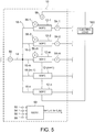
- FIG. 5 is a diagram illustrating a configuration of the fuel cell system 10 according to the second modification example. It is to be noted that a component similar to that of the first embodiment or the first modification example is assigned the same reference numeral, and its description is omitted.
- the fuel cell group 12 is composed of the n SOFC stacks 12-1, 12-2, ..., 12-(n-1), and 12-n.
- the (n-2) or less SOFC stacks12-1, 12-2, ..., and 12-m (2 ⁇ m ⁇ n-2) in the fuel cell group 12 are provided with the first outlet temperature sensors 54-1, 54-2, ..., and 54-m, respectively. Furthermore, the other SOFC stacks12-(m+1), 12-(m+2), ..., and 12-n are not provided with a temperature sensor at their air outlet.
- the SOFC stacks12-1, 12-2, ..., and 12-m correspond to the "first SOFC stack”. Furthermore, the SOFC stacks 12-(m+1), 12-(m+2), ..., and 12-n correspond to the "second SOFC stack”. That is, in the present modification example, there are the multiple "second SOFC stacks" provided with no temperature sensor at their air outlet.
- first SOFC stack 12-1 or the like in the first embodiment is changed into the "first SOFC stack 12-k"
- second SOFC stack 12-2 or the like in the first embodiment is changed into the "second SOFC stack 12-z”.
- respective reference numerals of the parameters described in the first embodiment are replaced as follows.
- FIG. 6 is a flowchart illustrating the flow of the calculation of the first individual supply flow rate q air1_d[k] and the second individual supply flow rate q air2_d[z] in the present modification example.
- the controller 60 performs similar processes to the processes at Steps S210 to S240 in FIG. 4 in the first modification example, and calculates respective first individual supply flow rates q air1_d[k] with respect to all integers k that meet 1 ⁇ k ⁇ m. That is, the controller 60 calculates first individual supply flow rates q air1_d[1] , q air1_d[2] , ..., and q air1_d[m] .
- Step S350 the controller 60 calculates a second individual supply flow rate q air2_d[z] from the obtained first individual supply flow rates q air1_d[1] , q air1_d[2] , ..., and q air1_d[m] on the basis of the following Expression (11).
- q air 2 _ d z q air ⁇ q air 1 _ d 1 + q air 1 _ d 2 + ⁇ ⁇ ⁇ + q air 1 _ d m n ⁇ m
- Expression (11) denotes a value obtained by subtracting the total sum of the first individual supply flow rates q air1_d[1] , q air1_d[2] , ..., and q air1_d[m] from the pre-distribution air flow rate q air and then dividing the obtained value by (n-m) that is the number of the second SOFC stacks 12-z.
- the second individual supply flow rate q air2_d[z] in the present modification example is calculated to be the same value among all the second SOFC stacks 12-z (m+1 ⁇ z ⁇ n).
- the present modification example as for at least all of the first SOFC stacks 12-k (1 ⁇ k ⁇ m), it is possible to find an individual flow rate of supplied air that takes variation into consideration. Meanwhile, as described above, as for the second SOFC stacks 12-z (m+1 ⁇ z ⁇ n), the same value is obtained as their second individual supply flow rate q air2_d[z] . Therefore, it is not possible to rigorously evaluate variation in the flow rate of supplied air among the second SOFC stacks 12-z.
- a ratio of the number of first SOFCs 12-k provided with a temperature sensor at their air outlet and the number of second SOFCs 12-z provided with a temperature sensor at their air outlet can be fittingly adjusted depending on the design, etc. of the fuel cell system 10. Accordingly, it is possible to adjust the balance between the high accuracy of temperature control and power generation amount control and the low cost fittingly. For example, if the number of the first SOFCs 12-k and the number of the second SOFCs 12-z are about the same, the number of temperature sensors installed can be about half of that is in a case where all the SOFCs composing the fuel cell group 12 are provided with a temperature sensor at their air outlet.
- FIG. 7 is a diagram illustrating a configuration of the fuel cell system 10 according to the third modification example. It is to be noted that a component similar to that of any of the first embodiment and the above-described modification examples 1 and 2 is assigned the same reference numeral, and its description is omitted.
- the fuel cell system 10 includes a merging path 17 [k, k+1] .
- a merging path 17 [k, k+1] In an SOFC group 12 [k, k+1] composed of two SOFC stacks 12-k and 12-(k+1), distribution paths 16-k and 16-(k+1) for supplying air to the SOFC stacks 12-k and 12-(k+1) are merged into the merging path 17 [k, k+1] at outlets of the SOFC stacks 12-k and 12-(k+1).
- the merging path 17 [k, k+1] is provided with a first outlet temperature sensor 54 [k, k+1] that detects an air temperature of the merging path 17 [k, k+1] .
- the SOFC stacks 12-k and 12-(k+1) are each provided with a voltage sensor 56-k.
- the air temperature in the merging path 17 [k, k+1] where the air from the SOFC group 12 [k, k+1] composed of the two SOFC stacks 12-k and 12-(k+ 1) is merged is detected as a "first outlet temperature”.
- the SOFC group 12 [k, k+1] composed of the two SOFC stacks 12-k and 12-(k+1) in the condition of 1 ⁇ k ⁇ N-2 corresponds to the "first SOFC stack".
- the SOFC group 12 [N-1, N] corresponds to the "second SOFC stack".
- the "SOFC group 12 [k, k+1] " and the "SOFC group 12 [N-1, N] " are referred to as the "first SOFC group 12 [k, k+1] " and the "second SOFC group 12 [N-1, N] ", respectively.
- a "first voltage V 1[k, k+1] " of the first SOFC group 12 [k, k+1] corresponds to "V 1[k] + V 1[k+1] " that is the sum of a first voltage V 1[k] of the SOFC stack 12-k and a first voltage V 1[k+1] of the SOFC stack 12-(k+1) in the first modification example.
- a "first calorific value Q gen1[k, k+1] " of the first SOFC group 12 [k, k+1] corresponds to "Q gen1[k] + Q gen1[k+1] " that is the sum of a "first calorific value Q gen1[k] " of the SOFC stack 12-k and a "first calorific value Q gen1[k+1] " of the SOFC stack 12-(k+1) in the first modification example.
- FIG. 8 is a flowchart illustrating the flow of the calculation of the first individual supply flow rate q air1_d[k, k+1] and the second individual supply flow rate q air2_d[N-1, N] in the present modification example.
- the controller 60 calculates a first calorific value Q gen1[k, k+1] due to power generation of the first SOFC group 12 [k, k+1] on the basis of a first voltage V 1[k+1] and a current I. Specifically, the controller 60 calculates a first calorific value Q gen1[k, k+1] , replacing "V 1[k] " and "E 0 " on the right side of Expression (6) described in the first modification example with "V 1[k] + V 1[k+1] " and “2E 0 ", respectively.
- controller 60 performs processes at Steps S420 to S450 in a similar way, replacing the respective parameters of Expressions (7) to (10) used at Steps S220 to S250 in the first modification example with the ones defined in the present modification example fittingly.
- the first SOFC groups 12 [k, k+1] and the second SOFC groups 12 [N-1, N] are an object of detection; therefore, an above-described ideal distribution air flow rate is determined on the basis of "N/2" that is the total number of these groups. That is, in Expressions (7) to (10), "q air /n" denoting the ideal distribution air flow rate is replaced with "2q air /N".
- the first individual supply flow rate q air1_d[k, k+1] and the second individual supply flow rate q air2_d[N-1, N] can be suitably calculated.
- the first individual supply flow rate q air1_d[k, k+1] and the second individual supply flow rate q air2_d[N-1, N] are estimated in units of the first SOFC group 12 [k, k+1] and the second SOFC group 12 [N-1, N] with two SOFCs as one group. Therefore, it is not possible to rigorously evaluate variation in the flow rate of supplied air among single SOFCs composing the fuel cell group 12.
- the fuel cell system 10 without having to rigorously evaluate variation in the flow rate of supplied air among single SOFCs, there may not be large errors in temperature control, power generation amount control, etc.
- the system configuration according to the present modification example it becomes possible to reduce the number of temperature sensors installed while maintaining the accuracy of temperature control and power generation amount control.
- the first outlet temperature sensor 54 [k, k+1] is provided for each first SOFC group 12 [k, k+1] with two SOFCs as one group, and thus the number of temperature sensors installed can be reduced by more than half. As a result, it is possible to further enhance the cost suppressing effect.
- first SOFC groups 12 [k, k+1] and the second SOFC groups 12 [N-1, N] are provided.
- first SOFC groups and second SOFC groups 12 may be provided.
- the number of SOFCs included in each SOFC group may be different among the SOFC groups.
- a second embodiment is described below. It is to be noted that a component similar to that of any of the first embodiment and the first to third modification examples is assigned the same reference numeral, and its description is omitted.
- FIG. 9 is a diagram illustrating a configuration of the fuel cell system 10 according to the second embodiment.
- the fuel cell system 10 according to the present embodiment is based on the configuration of the fuel cell system 10 according to the first modification example illustrated in FIG. 3 .
- the fuel cell system 10 according to the present embodiment includes a pre-supply refrigerant temperature sensor 59 that detects a pre-supply air temperature T in that is an air temperature in the air supply passage 14 and a voltage sensor 56-n that detects a second voltage V 2[n] that is a voltage of the second SOFC stack 12-n, in addition to the configuration of the fuel cell system 10 according to the first modification example.
- the controller 60 acquires the pre-supply air temperature T in from the pre-supply refrigerant temperature sensor 59 and the second voltage V 2[n] from the voltage sensor 56-n, besides respective detection signals from the sensors described in the first modification example.
- FIG. 10 is a flowchart illustrating the flow of the calculation of the second outlet temperature T o2exp[n] in the present embodiment.
- this second calorific value Q gen2[n] may be performed in advance, for example, in a stage of Step S210 in FIG. 4 .
- Step S520 the controller 60 sets a theoretical formula of a second outlet temperature T O2exp[n] shown in the following Expression (13).
- T O 2 exp n T in + Q gen 2 n q air 2 _ d n ⁇ c air
- Step S530 the controller 60 calculates the second outlet temperature T O2exp[n] using the already-calculated second individual supply flow rate q air2_d[n] in Expression (13).
- the second outlet temperature T O2exp[n] can be calculated by substituting the second individual supply flow rate q air2_d[n] calculated in Expressions (9) and (10) for Expression (13).
- T O2exp[n] in this case is determined as shown in the following Expression (14).
- T O 2 exp 2 T in + Q gen 2 2 2 Q gen 1 1 + q air ⁇ c air T O 1 1 ⁇ T O 1 1 exp q air ⁇ c air Q gen 1 1 + q air ⁇ c air T O 1 1 ⁇ T O 1 1 exp
- the fuel cell system 10 according to the present embodiment described above achieves the following functions and effects.
- the fuel cell system 10 further includes the pre-supply refrigerant temperature sensor 59 as a pre-supply refrigerant temperature detecting unit that detects a pre-supply air temperature T in as a pre-supply refrigerant temperature that is a temperature of a refrigerant before it is supplied to the SOFC stacks 12-1 to 12-n.
- the pre-supply refrigerant temperature sensor 59 as a pre-supply refrigerant temperature detecting unit that detects a pre-supply air temperature T in as a pre-supply refrigerant temperature that is a temperature of a refrigerant before it is supplied to the SOFC stacks 12-1 to 12-n.
- the voltage sensor 56-n as a voltage acquiring unit detects a second voltage V 2[n] that is a voltage of the second SOFC stack 12-n.
- the current sensor 58 as a current acquiring unit detects a current I as a second current of the second SOFC stack 12-n.
- the controller 60 calculates a second outlet temperature T O2exp[n] that is an air outlet temperature of the second SOFC stack 12-n on the basis of the second voltage V 2[n] , the current I, the pre-supply air temperature T in , and the second individual supply flow rate first individual supply flow rate (Steps S510 to S520 in FIG. 10 ).
- the second outlet temperature T O2exp[n] that is an air outlet temperature of the second SOFC stack 12-n provided with no outlet temperature sensor.
- the second individual supply flow rate q air2_d[n] in which the above-described variation in the flow rate of distributed air is reflected is used in the calculation of the second outlet temperature T o2exp[n] ; therefore, it is possible to obtain the accurate second outlet temperature T o2exp[n] that takes into consideration the variation in the flow rate of distributed air. That is, this can be accurately estimated without having to detect an outlet temperature of the second SOFC stack 12-n. As a result, it is possible to acquire an accurate air outlet temperature of the second SOFC stack 12-n provided with no outlet temperature sensor while reducing the number of temperature sensors at the air outlets of the second SOFC stacks 12-n and thereby reducing the cost.
- a second outlet temperature T o2exp[n] is calculated in the fuel cell system 10 based on the configuration of the first modification example.
- a second outlet temperature may be calculated in the fuel cell system 10 based on the configuration of the first embodiment, the configuration of the second modification example, or the configuration of the third modification example as well.
- a second outlet temperature can be calculated by performing processes similar to those at Steps S510 to S530 in the present embodiment.
- FIG. 11 is a diagram illustrating a configuration of the fuel cell system 10 according to the third embodiment.
- the fuel cell system 10 includes a fuel supply system that supplies fuel (fuel gas) for power generation to the SOFC stacks 12-1 to 12-n, in addition to the configuration of the second fuel cell system 10 illustrated in FIG. 9 .
- the fuel supply system in the present embodiment includes a fuel pump 80, a fuel supply passage 82 that is a passage through which fuel is supplied from the fuel pump 80 to the SOFC stacks 12-1 to 12-n, and a fuel flow rate sensor 84 that detects a flow rate of fuel fed from the fuel pump 80 into the fuel supply passage 82.
- the flow rate of fuel detected by the fuel flow rate sensor 84 is also referred to as a “total supply fuel flow rate q fuel ".
- the fuel supply passage 82 includes fuel distribution pipes 82a through which fuel is individually distributed to the SOFC stacks 12-1 to 12-n.
- the fuel distribution pipes 82a are each provided with a device (not shown) such as an injector or an opening degree control valve that controls fuel supply to the corresponding SOFC stack 12. By controlling these devices individually or collectively, respective distribution flow rates of fuel supply to SOFC stacks 12-1 to 12-n can be adjusted.
- the controller 60 acquires a total supply fuel flow rate q fuel that is a detected value of the fuel flow rate sensor 84 besides respective detection signals from the sensors described in the second embodiment.
- controller 60 calculates a heat capacity of supply fuel on the basis of the total supply fuel flow rate q fuel , and corrects a first calorific value Q gen1[k] and a second calorific value Q gen2[n] on the basis of the heat capacity of supply fuel. Its details are described below.
- FIG. 12 is a flowchart illustrating a method of calculating a first individual supply flow rate q air1_d[k] , a second individual supply flow rate q air2_d[n] , and a second outlet temperature T o2exp[n] , including a process of correcting a first calorific value Q gen1[k] and a second calorific value Q gen2[n] .
- the controller 60 calculates a corrected first calorific value Q gen1_cor[k] from a first calorific value Q gen1[k] . Specifically, as with Step S210 ( FIG. 4 ) described in the first modification example, on the basis of Expression (6), the controller 60 first calculates a first calorific value Q gen1[k] on the basis of a first voltage V 1[k] and a first current I.
- the controller 60 calculates a corrected first calorific value Q gen1_cor[k] by correcting the calculated first calorific value Q gen1[k] using a total supply fuel flow rate q fuel detected by the fuel flow rate sensor 84.
- Q gen 1 _ cor k Q gen 1 k 1 ⁇ C fuel 1 k C air 1 k
- C fuel1[k] in Expression (15) denotes a heat capacity of fuel supplied to the first SOFC stack 12-k.
- this heat capacity is also referred to as a “first SOFC supply fuel heat capacity C fuel1[k] ".
- C fuel denotes a specific heat capacity of fuel supplied to the first SOFC stack 12-k.
- this is also referred to as a “fuel specific heat C fuel ".
- a fixed value determined in an experiment or the like in advance is used as the "fuel specific heat C fuel " in the present embodiment.
- the "fuel specific heat C fuel” is set to be the same value among the SOFC stacks 12-1 to 12-n.
- C air1[k] denotes a heat capacity of air supplied to the first SOFC stack 12-k.
- this is also referred to as a “first SOFC supply air heat capacity C air1[k] ".
- the controller 60 can calculate a corrected first calorific value Q gen1_cor[k] by applying the first SOFC supply fuel heat capacity C fuel1[k] obtained by Expression (16), the first SOFC supply air heat capacity C air1[k] obtained by Expression (17), and the first calorific value Q gen1[k] to Expression (15).
- a flow rate of fuel supplied to the anode of the first SOFC stack 12-k is reduced by about ten orders as compared with a flow rate of air supplied to the cathode of the first SOFC stack 12-k. That is, it may be said that basically, a heat capacity of fuel supplied to the first SOFC stack 12-k is negligibly small as compared with a heat capacity of air supplied to the first SOFC stack 12-k.
- the corrected first calorific value Q gen1_cor[k] that takes heat transmission to fuel into consideration is found, and therefore, even in a case where heat transmission to the fuel is not negligible, it is possible to calculate the first individual supply flow rate q air1_d[k] , the second individual supply flow rate q air2_d[n] , and the second outlet temperature T o2exp[n] with high accuracy.
- the corrected first calorific value Q gen1_cor[k] that has been reduced by the transmission to the fuel can be used, and therefore, the accuracy of estimation of the first individual supply flow rate q air1_d[k] , etc. is further improved.
- the controller 60 performs processes at Steps S620 to S650 using the corrected first calorific value Q gen1_cor[k] .
- the controller 60 performs processes similar to Steps S220 to S250 in the above-described first modification example, replacing the "first calorific value Q gen1[k] " with the "corrected first calorific value Q gen1_cor[k] ". That is, the controller 60 performs respective calculations based on the above-described Expressions (7) to (10), and calculates a first individual supply flow rate q air1_d[k] and a second individual supply flow rate q air2_d[n] .
- Step S660 the controller 60 finds a corrected second calorific value Q gen2_cor[n] in a similar way to the above-described Step S610.
- the controller 60 calculates a corrected second calorific value Q gen2_cor[n] on the basis of a second calorific value Q gen2[n] of the second SOFC stack 12-n, determining a second SOFC supply fuel heat capacity C fuel2[n] as a heat capacity of fuel supplied to the second SOFC stack 12-n and a second SOFC supply air heat capacity C air2[n] as a heat capacity of air supplied to the second SOFC stack 12-n.
- Steps S670 and S680 the controller 60 calculates a second outlet temperature T o2exp[n] in a similar way to Steps S520 and S530 (see FIG. 10 ) described in the second embodiment.
- the second outlet temperature T o2exp[n] that is an air outlet temperature of the second SOFC stack 12-n with higher accuracy, taking into consideration the transmission to fuel supplied to the SOFC stack 12.
- the fuel cell system 10 according to the present embodiment described above achieves the following functions and effects.
- the fuel cell system 10 further includes the fuel flow rate sensor 84 as a fuel flow rate acquiring unit that detects a total supply fuel flow rate q fuel as a flow rate of fuel supplied to the fuel cell group 12.
- the controller 60 calculates a first SOFC supply fuel heat capacity C fuel1[k] and a second SOFC supply fuel heat capacity C fuel2[n] that are a heat capacity of fuel on the basis of the total supply fuel flow rate q fuel , and corrects the first individual supply flow rate q air1_d[k] , the second individual supply flow rate q air2_d[n] , and the second outlet temperature T o2exp[n] on the basis of the first SOFC supply fuel heat capacity C fuel1[k] and the second SOFC supply fuel heat capacity C fuel2[n] (Steps S610 to S680 in FIG. 12 ).
- the fuel flow rate sensor 84 is provided to detect a total supply fuel flow rate q fuel .
- the total supply fuel flow rate q fuel may be estimated by another means without providing the fuel flow rate sensor 84.
- the total supply fuel flow rate q fuel may be estimated on the basis of changes in the fuel level of a fuel tank (not shown) as a fuel supply source or a duty ratio of the fuel pump 80.
- a flow rate of fuel supplied to each SOFC stack 12 is assumed to be q fuel /n.
- an injector, an opening degree control valve, or the like may be provided in each of the fuel distribution pipes 82a, and respective individual supply fuel flow rates of the SOFC stacks 12-1 to 12-n may be estimated from respective individual fuel flow rate control amounts for the SOFC stacks 12-1 to 12-n, and then, with respect to each individual stack, a first SOFC supply fuel heat capacity C fuel1[k] and a second SOFC supply fuel heat capacity C fuel2[n] may be calculated on the basis of the individual supply fuel flow rates.
- the ideal distribution air flow rate q air /n on the right side may be replaced with a value of a flow rate of air that takes into consideration the variation in the flow rate of air among the SOFC stacks 12-1 to 12-n.
- a preliminary first individual supply flow rate q air1_d[k] and a preliminary second individual supply flow rate q air2_d[n] may be calculated from the uncorrected first calorific value Q gen1[k] and the uncorrected second calorific value Q gen2[n] in the present embodiment by a similar method to the first modification example, and these preliminary flow rates of air may be used instead of the ideal distribution air flow rate q air /n on the right side.
- FIG. 13 is a diagram illustrating a configuration of the fuel cell system 10 according to the fourth embodiment.
- the fuel cell system 10 includes an air pump 86 as a refrigerant adjusting device that adjusts the flow rate of air in the air supply passage 14 in addition to the configuration of the fuel cell system 10 according to the second embodiment illustrated in FIG. 9 .
- the controller 60 controls the output of the air pump 86 on the basis of a first outlet temperature T o1[k] detected by the first outlet temperature sensor 54-k and a second outlet temperature T o2exp[n] calculated through the processes (at Steps S510 to S530 in FIG. 10 ) described in the second embodiment, and adjusts the flow rate of air in the air supply passage 14.
- a flow rate control outlet temperature T o_f_cont is calculated by applying all values from 0 to n-1 to k. Therefore, the flow rate control outlet temperature T o_f_cont is set to the highest value in all the first outlet temperatures T o1[1] , T o1[2] , ..., and T o1[n-1] and the second outlet temperature T o2exp[n] .
- FIG. 14 is a flowchart illustrating the flow of air flow rate control in the present embodiment.
- the controller 60 controls the output of the air pump 86 so as to bring the flow rate control outlet temperature T o_f_cont closer to a predetermined target temperature. Specifically, as the flow rate control outlet temperature T o_f_cont moves away from the target temperature in a direction of getting lower, the controller 60 makes the output of the air pump 86 lower. Furthermore, as the flow rate control outlet temperature T o_f_cont moves away from the target temperature in a direction of getting higher, the controller 60 makes the output of the air pump 86 higher.
- the fuel cell system 10 according to the present embodiment described above achieves the following functions and effects.
- the fuel cell system 10 further includes the air pump 86 as a refrigerant adjusting device that adjusts the flow rate of air in the air supply passage 14. Then, the controller 60 adjusts the flow rate of air in the air supply passage 14 by controlling the air pump 86 on the basis of the first outlet temperature T o1[k] and the second outlet temperature T o2exp[n] (Steps S710 and S720 in FIG. 14 ).
- the flow rate of air in the air supply passage 14 is controlled on the basis of the detected first outlet temperature T o1[k] of the first SOFC stack 12-k and the second outlet temperature T o2exp[n] of the second SOFC stack 12-n estimated through the processes described in the above-described second embodiment, etc. That is, the flow rate of air in the air supply passage 14 is controlled on the basis of air outlet temperature information that takes into consideration the variation in the flow rate of supplied air among the first SOFC stacks 12-k and the second SOFC stack 12-n, and therefore the flow rate of air to be supplied to each one (a target air flow rate) can be set more appropriately. As a result, it is possible to perform the temperature control of the first SOFC stacks 12-k and the second SOFC stack 12-n more suitably.
- the controller 60 controls the air pump 86 on the basis of the flow rate control outlet temperature T o_f_cont that is either the first outlet temperature T o1[k] or the second outlet temperature T o2exp[n] , whichever is higher (Step S720 in FIG. 14 ).
- a fifth embodiment is described below. It is to be noted that a component similar to that of any of the above-described embodiments and the modification examples is assigned the same reference numeral, and its description is omitted.
- FIG. 15 is a diagram illustrating a configuration of the fuel cell system 10 according to the fifth embodiment.
- the fuel cell system 10 according to the present embodiment is based on the configuration of the fuel cell system 10 according to the fourth embodiment illustrated in FIG. 13 .
- the fuel cell system 10 according to the present embodiment further includes a power adjusting device 90 as a power adjusting device that adjusts generating power (an extraction current) of each of the SOFC stacks 12-1 to 12-n in addition to the configuration of the fourth embodiment.
- this power adjusting device 90 includes a DC/DC converter, etc.
- the power adjusting device 90 is configured to be able to individually adjust the generating power of the first SOFC stacks 12-k (1 ⁇ k ⁇ n-1) and the second SOFC stack 12-n.
- the controller 60 can basically control the generating power of the first SOFC stack 12-k (1 ⁇ k ⁇ n-1) on the basis of the first outlet temperature T o1[k] , and control the generating power of the second SOFC stack 12-n on the basis of the second outlet temperature T o2exp[n] .
- the controller 60 performs generating power control based on a power control outlet temperature T o_g_cont that takes a safety margin into consideration. Its details are described below.
- FIG. 16 is a flowchart illustrating the generating power control in the present embodiment.
- the power control outlet temperature T o_g_cont is calculated by applying all values from 0 to n-1 to k. Therefore, the power control outlet temperature T o_g_cont is set to the highest value in all the first outlet temperatures T o1[1] , T o1[2] , ..., and T o1[n-1] and the second outlet temperature T o2exp[n] .
- the controller 60 controls the power adjusting device 90 so as to bring the power control outlet temperature T o_g_cont closer to a predetermined target temperature. Specifically, as the power control outlet temperature T o_g_cont moves away from the target temperature in a direction of getting lower, the controller 60 controls the power adjusting device 90 to make the electric power (the calorific value) extracted from each SOFC stack 12 lower. Furthermore, as the further the power control outlet temperature T o_g_cont moves away from the target temperature in a direction of getting higher, the controller 60 controls the power adjusting device 90 to make the electric power (the calorific value) extracted from each SOFC stack 12 higher.
- the controller 60 determines whether or not the power control outlet temperature T o_g_cont is higher than a predetermined threshold temperature T th in a state where the power adjusting device 90 is controlled at Step S820.
- the threshold temperature T th is a value determined in an experiment or the like in terms of preventing the temperatures of the first SOFC stacks 12-k and the second SOFC stack 12-n from getting too high in consideration of the heat resistance, etc. according to the specifications of the first SOFC stacks 12-k and the second SOFC stack 12-n.
- the controller 60 When having determined that the power control outlet temperature T o_g_cont is not higher than the threshold temperature T th , the controller 60 continues the generating power control at Step S820. On the other hand, when having determined that the power control outlet temperature T o_g_cont is higher than the threshold temperature T th , the controller 60 performs a process at Step S840.
- the controller 60 controls the power adjusting device 90 to cause the power generation of the first SOFC stacks 12-k and the second SOFC stack 12-n to be stopped. That is, if the power control outlet temperature T o_g_cont becomes higher than a certain level, the controller 60 causes the power adjusting device 90 to stop the power generation of the first SOFC stacks 12-k and the second SOFC stack 12-n in terms of heat-resistance protection, etc.
- the fuel cell system 10 according to the present embodiment described above achieves the following functions and effects.
- the fuel cell system 10 further includes the power adjusting device 90 that adjusts the generating power of the SOFC stacks 12. Then, the controller 60 controls the power adjusting device 90 on the basis of the first outlet temperature T o1[k] and the second outlet temperature T o2exp[n] (Steps S810 to S840 in FIG. 16 ).
- the generating power of the SOFC stacks 12 is controlled on the basis of the detected first outlet temperature T o1[k] of the first SOFC stack 12-k and the second outlet temperature T o2exp[n] of the second SOFC stack 12-n estimated through the processes described in the above-described second embodiment, etc. That is, the generating power of the SOFC stacks 12 is controlled on the basis of the air outlet temperature information that takes into consideration the variation in the flow rate of supplied air among the first SOFC stacks 12-k and the second SOFC stack 12-n, and therefore it is possible to perform control of the respective calorific values of the first SOFC stacks 12-k and the second SOFC stack 12-n based on the adjustment of the generating power with higher accuracy.
- the controller 60 controls the power adjusting device 90 on the basis of the power control outlet temperature T o_g_cont that is either the first outlet temperature T o1[k] or the second outlet temperature T o2exp[n] , whichever is higher (Step S810 in FIG. 16 ).
- the generating power of the first SOFC stacks 12-k and the second SOFC stack 12-n is likely to be controlled to a direction of further decreasing the calorific value, and therefore it is possible to further improve the safety in terms of the heat resistance of the first SOFC stacks 12-k and the second SOFC stack 12-n.
- the controller 60 causes the power adjusting device 90 to stop the power generation of the first SOFC stacks 12-k and the second SOFC stack 12-n (Steps S830 and S840 in FIG. 16 ).
- the power control outlet temperature T o_g_cont set to the safety side in terms of heat-resistance protection exceeds the threshold temperature T th , the power generation is stopped to stop the heat generation of the first SOFC stacks 12-k and the second SOFC stack 12-n.
- a pre-distribution air flow rate q air that is the sum of respective flow rates of air supplied to the SOFC stacks 12-1 and 12-n is detected by the pre-distribution air flow rate sensor 50.
- the pre-distribution air flow rate q air may be estimated from, for example, a set output of the air pump 86 used to supply air into the air supply passage 14.
- the SOFC stacks 12-1 and 12-n are arranged in parallel with the electric load, and this one current sensor 58 is provided and shared by them.
- all the SOFC stacks may be provided with a current sensor, or at least SOFC stacks having different currents from each other may be provided with a current sensor.
- a calorific value may be calculated with a different value of theoretical electromotive force fittingly set for each of the SOFC stacks 12-1 to 12-n.
- the fuel cell group 12 is composed of the SOFC stacks 12-1 to 12-n.
- the calculation method, the supply air flow rate control, and the generating power control according to any of the above-described embodiments and the modification examples can also be applied to a system in which at least part of the fuel cell group 12 is composed of unit fuel cells.
- the "air specific heat C air" used in calculation in the above-described embodiments and the modification examples and the “fuel specific heat C fue1 " used in calculation in the third embodiment both take a fixed value; however, for example, a corrected value may be used fittingly in consideration of variation in their value caused by factors, such as temperature.
Landscapes
- Life Sciences & Earth Sciences (AREA)
- Engineering & Computer Science (AREA)
- Manufacturing & Machinery (AREA)
- Sustainable Development (AREA)
- Sustainable Energy (AREA)
- Chemical & Material Sciences (AREA)
- Chemical Kinetics & Catalysis (AREA)
- Electrochemistry (AREA)
- General Chemical & Material Sciences (AREA)
- Fuel Cell (AREA)
Abstract
Description
- The present invention relates to a fuel cell system that cools a fuel cell by supplying a refrigerant, such as air, to the fuel cell and estimates a refrigerant flow rate at a refrigerant outlet of the fuel cell, and to estimation method for estimating a flow rate of a refrigerant supplied in the fuel cell system.
- There is known a fuel cell system that supplies a refrigerant, such as cooling water or air, to a fuel cell to control the temperature of the fuel cell to a predetermined temperature.
JP2007-188667 A - The fuel cell system disclosed in
JP2007-188667 A - Then, the fuel cell system estimates respective calorific values of cells from a measured voltage value, etc. of each cell group, and estimates a temperature difference (a difference between a pre-supply refrigerant temperature and a discharged refrigerant temperature) of each cell group on the basis of a detected inlet temperature value from the inlet temperature sensor, a detected outlet temperature value from the outlet temperature sensor, and the estimates of the calorific values.
- However, in the fuel cell system, a uniform flow rate of refrigerant is not necessarily distributed from the refrigerant supply passage to each refrigerant distribution passage. The flow rate of refrigerant distributed and supplied to each refrigerant distribution passage varies, for example, according to differences in various conditions, such as a pressure and a temperature in a refrigerant passage in each fuel cell group.
- Therefore, if there is such variation in the flow rate of supplied refrigerant, the degree of cooling differs among the fuel cell groups, and there is variation in real calorific value.
- Meanwhile, in the fuel cell system, the detected inlet temperature value and the detected outlet temperature value that are used for estimation of a calorific value of each fuel cell group only include temperature information before the distribution of the supplied refrigerant and temperature information after the discharged refrigerants are merged, respectively. As a result, this estimation of the calorific value does not take into consideration the variation in real calorific value among the fuel cell groups, and therefore the estimation accuracy of an estimate of the calorific value and an estimate of a temperature difference of each cell group based on this may be insufficient.
- Therefore, an object of the present invention is to allow a fuel cell system that cools a plurality of fuel cells by distributing a refrigerant to the fuel cells to estimate a flow rate of refrigerant supplied to each fuel cell with higher accuracy.
- An aspect of the present invention provides a fuel cell system comprising a fuel cell group including a plurality of fuel cells, a refrigerant distribution passage through which a refrigerant is individually distributed to the fuel cells composing the fuel cell group, a pre-distribution refrigerant flow rate acquiring unit configured to acquire a pre-distribution refrigerant flow rate that is a flow rate of the refrigerant before distribution, a first outlet temperature detecting unit that is provided at a refrigerant outlet of at least one first fuel cell in the fuel cell group in the refrigerant distribution passage, and is configured to detect a first outlet temperature that is a refrigerant outlet temperature of the first fuel cell, a voltage acquiring unit configured to acquire at least a first voltage that is a voltage of the first fuel cell, a current acquiring unit configured to acquire at least a first current that is a current of the first fuel cell, and a controller, wherein the controller calculates a first individual supply flow rate that is a flow rate of the refrigerant individually supplied to the first fuel cell on a basis of the first voltage, the first current, and the first outlet temperature, and a second individual supply flow rate that is a flow rate of the refrigerant individually supplied to at least one second fuel cell other than the first fuel cell on a basis of the first individual supply flow rate and the pre-distribution refrigerant flow rate.
-
-
FIG. 1 is a diagram illustrating a configuration of a fuel cell system according to a first embodiment. -
FIG. 2 is a flowchart illustrating the flow of calculation of a first individual supply flow rate and a second individual supply flow rate in the first embodiment. -
FIG. 3 is a diagram illustrating a configuration of a fuel cell system according to a first modification example. -
FIG. 4 is a flowchart illustrating the flow of calculation of a first individual supply flow rate and a second individual supply flow rate in the first modification example. -
FIG. 5 is a diagram illustrating a configuration of a fuel cell system according to a second modification example. -
FIG. 6 is a flowchart illustrating the flow of calculation of a first individual supply flow rate and a second individual supply flow rate in the second modification example. -
FIG. 7 is a diagram illustrating a configuration of a fuel cell system according to a third modification example. -
FIG. 8 is a flowchart illustrating the flow of calculation of a first individual supply flow rate and a second individual supply flow rate in the third modification example. -
FIG. 9 is a diagram illustrating a configuration of a fuel cell system according to a second embodiment. -
FIG. 10 is a flowchart illustrating the flow of calculation of a second outlet temperature in the second embodiment. -
FIG. 11 is a diagram illustrating a configuration of a fuel cell system according to a third embodiment. -
FIG. 12 is a flowchart illustrating the flow of calculation of a first individual supply flow rate, a second individual supply flow rate, and a second outlet temperature in the third embodiment. -
FIG. 13 is a diagram illustrating a configuration of a fuel cell system according to a fourth embodiment. -
FIG. 14 is a flowchart illustrating the flow of air flow rate control in the fourth embodiment. -
FIG. 15 is a diagram illustrating a configuration of a fuel cell system according to a fifth embodiment. -
FIG. 16 is a flowchart illustrating the flow of generating power control in the fifth embodiment. - Embodiments of the present invention are described below with reference to accompanying drawings.
-
FIG. 1 is a diagram illustrating a configuration of a fuel cell system according to a first embodiment. - As shown in the drawing, a
fuel cell system 10 includes afuel cell group 12 including two solid oxide fuel cell (SOFC) stacks 12-1 and 12-2 that are a plurality of fuel cells, anair supply passage 14 that is a refrigerant supply passage through which air as a refrigerant is supplied to thefuel cell group 12, and anair distribution passage 16 as a refrigerant distribution passage through which the air is individually distributed to the SOFC stacks 12-1 and 12-2 composing thefuel cell group 12. It is to be noted that in the present embodiment, the "SOFC stack 12-1" corresponds to a "first fuel cell", and the "SOFC stack 12-2" corresponds to a "second fuel cell". Therefore, hereinafter, the "SOFC stack 12-1" and the "SOFC stack 12-2" are also referred to as the "first SOFC stack 12-1" and the "second SOFC stack 12-2", respectively. - Then, the first SOFC stack 12-1 and the second SOFC stack 12-2 are arranged in parallel with an
electric load 100 including a traction motor, various auxiliary machines, a predetermined battery, etc. that are not shown. - The first SOFC stack 12-1 and the second SOFC stack 12-2 are both a fuel cell stack in which a plurality of SOFC cells each obtained by holding an electrolyte layer made of solid oxide, such as ceramic, between an anode (a fuel electrode) and a cathode (an air electrode) is stacked. Then, the first SOFC stack 12-1 and the second SOFC stack 12-2 cause fuel gas (hydrogen) supplied to the fuel electrode from a fuel supply system (not shown) to react with oxidizing gas (air) supplied to the air electrode from an air supply system (not shown) or through the
air distribution passage 16, thereby generating electric power. - Furthermore, the
fuel cell group 10 includes a pre-distribution airflow rate sensor 50 and a firstoutlet temperature sensor 54. The pre-distribution airflow rate sensor 50 detects a pre-distribution air flow rate qair that is a flow rate of air in theair supply passage 14, i.e., a flow rate of air before it is distributed to all the SOFC stacks 12-1 and 12-2. The firstoutlet temperature sensor 54 is provided at an air outlet of the SOFC stack 12-1 in theair distribution passage 16, and detects a first outlet temperature To1[1] that is an outlet temperature of the SOFC stack 12-1. - The
air supply passage 14 is a passage for supplying air fed from an air blower or the like (not shown) to thefuel cell group 12. - The
air distribution passage 16 includes a first distribution path 16-1 through which air from theair supply passage 14 is distributed to the first SOFC stack 12-1 and a second distribution path 16-2 through which the air from theair supply passage 14 is distributed to the second SOFC stack 12-2. In this configuration, the air supplied to the first SOFC stack 12-1 and the second SOFC stack 12-2 through the first distribution path 16-1 and the second distribution path 16-2 cools the first SOFC stack 12-1 and the second SOFC stack 12-2, and then is discharged into, for example, a cooling device (not shown) or a discharged gas system (not shown). - Moreover, the
fuel cell system 10 includes avoltage sensor 56 and acurrent sensor 58. Thevoltage sensor 56 detects a first voltage V1[1] that is a voltage of the first SOFC stack 12-1. Thecurrent sensor 58 detects a current I as a first current that is a current of the first SOFC stack 12-1. - It is to be noted that in the present embodiment, the SOFC stacks 12-1 and 12-2 are arranged in parallel with the
electric load 100; therefore, the "first current" of the first SOFC stack 12-1 and a "second current" of the second SOFC stack 12-2 are both detected as a "current I". The same applies to first to third modification examples and second to fifth embodiments to be described later. - Furthermore, the
fuel cell system 10 includes acontroller 60. Thecontroller 60 calculates a first calorific value Qgen1[1] that is a calorific value of the first SOFC stack 12-1 on the basis of the first voltage V1[1] received from thevoltage sensor 56 and the current I received from thecurrent sensor 58. - Furthermore, the
controller 60 calculates a first individual supply flow rate qair1_d[1] that is a flow rate of air individually supplied to the first SOFC stack 12-1 through the first distribution path 16-1 on the basis of the pre-distribution air flow rate qair received from the pre-distribution airflow rate sensor 50, the first outlet temperature To1[1] received from the firstoutlet temperature sensor 54, and the calculated first calorific value Qgen1[1]. Moreover, thecontroller 60 calculates a second individual supply flow rate qair2_d[2] that is a flow rate of air individually supplied to the second SOFC stack 12-2 on the basis of the calculated first individual supply flow rate qair1_d[1]. - It is to be noted that the
controller 60 is configured of a computer, particularly, a microcomputer that includes a central processing unit (CPU), a read-only memory (ROM), a random access memory (RAM), and an input/output (I/O) interface. Then, thecontroller 60 is programmed, at least, to be able to execute processing required to perform respective processes associated with the present embodiment or any of later-described modification examples 1 to 3, or any of the second to fifth embodiments. - It is to be noted that the
controller 60 may be configured as one device, or may be configured of multiple devices so that the multiple devices share and process controls of the present embodiment. - Below are described details of calculation of the first individual supply flow rate qair1_d[1] and the second individual supply flow rate qair2_d[2].
-
FIG. 2 is a flowchart illustrating the flow of the calculation of the first individual supply flow rate qair1_d[1] and the second individual supply flow rate qair2_d[2]. - At Step S110, using the following Expression (1), the
controller 60 calculates a first calorific value Qgen1[1] due to power generation of the first SOFC stack 12-1 on the basis of a first voltage V1[1] and a current I.
[Math. 1]
- It is to be noted that "E0" in the expression denotes a theoretical electromotive force of the first SOFC stack 12-1.
- At Step S120, the
controller 60 sets a theoretical formula of an assumed first outlet temperature value To1exp[1] shown in the following Expression (2).
[Math. 2]
- It is to be noted that "Tin" in Expression (2) denotes a temperature of air in the air supply passage 14 (hereinafter, also referred to as a "pre-supply air temperature Tin"); "
q air/2" denotes a value obtained by dividing a pre-distribution air flow rate qair detected by the pre-distribution airflow rate sensor 50 by 2 that is the number of SOFCs disposed in thefuel cell group 12 in the present embodiment; and "cair" denotes a specific heat capacity of air (hereinafter, referred to simply as an "air specific heat cair"). - It is to be noted that a predetermined fixed value determined in an experiment or the like is used as the air specific heat cair. Furthermore, hereinafter, "qair/2", a value obtained by dividing the pre-distribution air flow rate qair by the number of the disposed SOFC stacks 12, is also referred to as an "ideal distribution air flow rate qair/2".
- Furthermore, the assumed first outlet temperature value To1exp[1] is a value of an outlet air temperature expected to be detected by the first SOFC stack 12-1 if a uniform flow rate of air is distributed from the
air supply passage 14 to the first distribution path 16-1 and the second distribution path 16-2 (i.e., if there is no variation in the flow rate of air at the time of distribution). - Moreover, a denominator of a second term on the right side in Expression (2), i.e., a value obtained by multiplying the ideal distribution air flow rate qair/2 and the air specific heat cair corresponds to a heat capacity per unit time of air supplied to the first SOFC stack 12-1 (hereinafter, also referred to simply as a "supply air heat capacity"). Therefore, the second term on the right side, where the first calorific value Qgen1[1] of the first SOFC stack 12-1 is divided by the supply air heat capacity, corresponds to a real temperature rise of the air due to heat generation of the first SOFC stack 12-1.
- Therefore, the second term on the right side is a value that the real temperature rise of the air due to heat generation of the first SOFC stack 12-1 based on the ideal distribution air flow rate qair/2 is added to the pre-supply air temperature Tin. That is, as shown in Expression (2), the second term on the right side equals to the assumed first outlet temperature value To1exp[1] on the left side.
- Next, at Step S130, the
controller 60 sets a theoretical formula of a first outlet temperature To1[1] shown in the following Expression (3) on the basis of the first calorific value Qgen1[1] of the first SOFC stack 12-1 obtained at Step S110.
[Math. 3]
- Then, at Step S140, the
controller 60 calculates a first individual supply flow rate qair1_d[1] on the basis of Expressions (2) and (3). Specifically, the first individual supply flow rate qair1_d[1] is calculated as shown in the following Expression (4).
[Math. 4]
- It is to be noted that in the above Expression (4), the term of the pre-supply air temperature Tin included in Expressions (2) and (3) is eliminated. Therefore, in the present embodiment, the
controller 60 can calculate the first individual supply flow rate qair1_d[1] on the basis of the pre-distribution air flow rate qair detected by the pre-distribution airflow rate sensor 50, the first outlet temperature To1[1] detected by the firstoutlet temperature sensor 54, and the first calorific value Qgen1[1] calculated at Step S110. - Then, at Step S150, the
controller 60 calculates a second individual supply flow rate qair2_d[2], which is a flow rate of air supplied to the second SOFC stack 12-2, from the obtained first individual supply flow rate qair1_d[1]. Specifically, as shown in the following Expression (5), the second individual supply flow rate qair2_d[2] is calculated by subtracting the first individual supply flow rate qair1_d[1] from the pre-distribution air flow rate qair (= 2q).
[Math. 5]
- Therefore, according to the present embodiment, it is possible to find the first individual supply flow rate qair1_d[1] of the first SOFC stack 12-1 and the second individual supply flow rate qair2_d[2] of the second SOFC stack 12-2 that take into consideration the variation in the flow rate of air distributed from the
air supply passage 14 to the first distribution path 16-1 and the second distribution path 16-2. - The
fuel cell system 10 according to the present embodiment described above achieves the following functions and effects. - The fuel cell system 10 according to the present embodiment includes: the fuel cell group 12 including the first SOFC stack 12-1 and the second SOFC stack 12-2 that are a plurality of fuel cells; the air distribution passage 16 as a refrigerant distribution passage through which air is individually distributed to the first SOFC stack 12-1 and the second SOFC stack 12-2 that compose the fuel cell group 12; the pre-distribution air flow rate sensor 50 as a pre-distribution refrigerant flow rate acquiring unit that acquires, as a pre-distribution refrigerant flow rate, a pre-distribution air flow rate qair that is a flow rate of air before distribution; the first outlet temperature sensor 54 as a first outlet temperature detecting unit that is provided at a refrigerant outlet of the first SOFC stack 12-1 as a first fuel cell, which is one of the fuel cell group 12, in the first distribution path 16-1 of the air distribution passage 16 and detects a first outlet temperature (a first outlet temperature To1[1]) that is an air outlet temperature of the first SOFC stack 12-1; the voltage sensor 56 as a voltage acquiring unit that acquires a first voltage V1[1] that is a voltage of the first SOFC stack 12-1; the current sensor 58 as a current acquiring unit that acquires a current I (a first current) that is a current of the first SOFC stack 12-1; and the controller 60.
- Then, the
controller 60 calculates a first individual supply flow rate qair1_d[1] that is a flow rate of refrigerant individually supplied to the first SOFC stack 12-1 on the basis of the first voltage V1[1], the current I, and the first outlet temperature To1[1] (Steps S110 to S140 inFIG. 2 ), and calculates a second individual supply flow rate qair2_d[2] that is a flow rate of refrigerant individually supplied to the one second SOFC stack 12-2 other than the first SOFC stack 12-1 on the basis of the first individual supply flow rate qair1_d[1] and the pre-distribution air flow rate qair (Step S150 inFIG. 2 ). - That is, the present embodiment provides a refrigerant flow rate estimation method for estimating a flow rate of air to be supplied in the
fuel cell system 10 that individually distributes and supplies air as a refrigerant to the first SOFC stack 12-1 and the second SOFC stack 12-2 that are a plurality of fuel cells composing thefuel cell group 12. Then, in this refrigerant flow rate estimation method, a first individual supply flow rate qair1_d[1] that is a flow rate of refrigerant individually supplied to the first SOFC stack 12-1 is calculated on the basis of a pre-distribution air flow rate qair that is a flow rate of refrigerant before distribution, a first outlet temperature To1[1] detected at the air outlet of the first SOFC stack 12-1 as at least one first fuel cell of thefuel cell group 12, a first voltage V1[1] that is a voltage of the first SOFC stack 12-1, and a current I as a first current that is a current of the first SOFC stack 12-1 (Steps S110 to S140 inFIG. 2 ). Then, a second individual supply flow rate qair2_d[2] that is a flow rate of refrigerant individually supplied to the second SOFC stack 12-2 other than the first SOFC stack 12-1 is calculated on the basis of the first individual supply flow rate qair1_d[1] and the pre-distribution air flow rate qair (Step S150 inFIG. 2 ). - Accordingly, in a case where air as a refrigerant is distributed to a plurality of disposed SOFCs, it is possible to find a first individual supply flow rate qair1_d[1] of the first SOFC stack 12-1 whose outlet temperature (first outlet temperature To1[1]) is detected by the first
outlet temperature sensor 54 and also estimate a flow rate of air supplied to the second SOFC stack 12-2 on the basis of this first individual supply flow rate qair1_d[1] and a pre-distribution air flow rate qair. - Therefore, even if there is variation in the flow rate of supplied air between the first SOFC stack 12-1 and the second SOFC stack 12-2, the accurate first individual supply flow rate qair1_d[1] is found in the first SOFC stack 12-1 whose outlet temperature is detected, and thus the flow rate of air supplied to the second SOFC stack 12-2 in which the variation in the flow rate of supplied air is reflected can be estimated by referring to this first individual supply flow rate qair1_d[1] and the pre-distribution air flow rate qair. That is, it is possible to estimate individual flow rates of air supplied to the first SOFC stack 12-1 and the second SOFC stack 12-2 with higher accuracy.
- Consequently, temperature control, power generation control, etc. using the flow rates of air supplied to the first SOFC stack 12-1 and the second SOFC stack 12-2 can be also performed with higher accuracy.
- In the present embodiment, particularly, the
controller 60 calculates the second individual supply flow rate qair2_d[2] of the second SOFC stack 12-2 from the first individual supply flow rate qair1_d[1] of the first SOFC stack 12-1 provided with the first outlet temperature sensor 54-1 at its air outlet. Therefore, it is possible to find the second individual supply flow rate qair2_d[2] without installing a temperature sensor or a flow rate detection sensor at an air outlet of the second SOFC stack 12-2. Accordingly, as compared with an existing fuel cell system in which a temperature sensor is installed at an air outlet of each fuel cell composing thefuel cell group 12, it is possible to reduce the number of temperature sensors installed, and is possible to reduce the cost of manufacturing the system and the maintenance cost of the temperature sensors. - Subsequently, the first modification example of the first embodiment is described. It is to be noted that a component similar to that of the first embodiment is assigned the same reference numeral, and its description is omitted. Furthermore, in the present modification example, particularly, there is described estimation of a first individual supply flow rate and a second individual supply flow rate in the
fuel cell system 10 in which thefuel cell group 12 is composed of n (n is any positive integer) SOFC stacks. It is to be noted that the above-described first embodiment corresponds to a case of n = 2 in the present modification example. -
FIG. 3 is a diagram illustrating a configuration of thefuel cell system 10 according to the first modification example. - As shown in the drawing, in the first modification example, the
fuel cell group 12 is composed of n SOFC stacks 12-1, 12-2, ..., 12-(n-1), and 12-n. Then, theair distribution passage 16 through which air from theair supply passage 14 is distributed to these SOFCs is composed of n passages that are first to nth distribution paths 16-1 to 16-n corresponding to the n SOFCs. - Then, the SOFC stacks 12-1, 12-2, ..., and 12-(n-1) are provided with voltage sensors 56-1, 56-2, ..., and 56-(n-1) corresponding to the
voltage sensor 56 in the first embodiment, respectively. Furthermore, first outlet temperature sensors 54-1, 54-2, ..., and 54-(n-1) corresponding to the firstoutlet temperature sensor 54 in the first embodiment are provided at air outlets of the SOFC stacks 12-1, 12-2, ..., and 12-(n-1), i.e., the SOFC stacks other than the SOFC stack 12-n, respectively. - Therefore, in the present modification example, the SOFC stacks 12-1, 12-2, ..., and 12-(n-1) correspond to the "first SOFC stack 12-1" in the first embodiment. Furthermore, the SOFC stack 12-n corresponds to the "second SOFC stack 12-2" in the first embodiment.
- It is to be noted that in the present modification example, for the sake of simplicity of description, description about the n-1 first SOFC stacks 12-1, 12-2, ..., and 12-(n-1) and their peripheral structure is condensed by using an integer k in a range of 1 ≤ k ≤ n-1 as needed. However, this description holds true for any integer k that meets 1 ≤ k ≤ n-1.
- That is, in the present modification example, the "first SOFC stack 12-1" or the like in the first embodiment is changed into the "first SOFC stack 12-k", and the "second SOFC stack 12-2" or the like in the first embodiment is changed into the "second SOFC stack 12-n". In accordance with this, respective reference numerals of the parameters described in the first embodiment are replaced as follows.
-
- "first outlet temperature To1[1]" => "first outlet temperature To1[k]"
- "first voltage V1[1]" => "first voltage V1[k]"
- "first calorific value Qgen1[1]" => "first calorific value Qgen1[k]"
- "assumed first outlet temperature value To1exp[1]" => "assumed first outlet temperature value To1p[k]"
- "first individual supply flow rate qair1_d[1]" => "first individual supply flow rate qair1_d[k]"
- "second individual supply flow rate qair2_d[2]" => "second individual supply flow rate qair2_d[n]"
- Below are described details of calculation of a first individual supply flow rate qair1_d[k] and a second individual supply flow rate qair2_d[n] in the present modification example.
-
FIG. 4 is a flowchart illustrating the flow of the calculation of the first individual supply flow rate qair1_d[k] and the second individual supply flow rate qair2_d[n] in the present modification example. - At Step S210, using the following Expression (6), the
controller 60 calculates a first calorific value Qgen1[k] due to power generation of the first SOFC stack 12-k on the basis of a first voltage V1[k] and a current I.
[Math. 6]
- At Step S220, the
controller 60 sets a theoretical formula of an assumed first outlet temperature value To1exp[k] shown in the following Expression (7).
[Math. 7]
- It is to be noted that as described in the above embodiment, "qair/n" in Expression (7) corresponds to the ideal distribution air flow rate described in the first embodiment.
- At Step S230, the
controller 60 sets a theoretical formula of a first outlet temperature To1[k] shown in the following Expression (8) on the basis of the first calorific value Qgen1[k] obtained at Step S210.
[Math. 8]
- Then, at Step S240, the
controller 60 calculates a first individual supply flow rate qair1_d[k] on the basis of Expressions (7) and (8). Specifically, the first individual supply flow rate qair1_d[k] is calculated as shown in the following Expression (9).
[Math. 9]
- Therefore, also in the present modification example, the term of the pre-supply air temperature Tin included in Expressions (2) and (3) is eliminated, and the
controller 60 can calculate the first individual supply flow rate qair1_d[k] from the pre-distribution air flow rate qair, the first outlet temperature To1[k], the first voltage V1[k], and the current I that are detected values. - In the present modification example, particularly, the above-described Steps S210 to S240 are performed on all integers k that meet 1 ≤ k ≤ n-1, and thereby all of first individual supply flow rates qair1_d[1], qair1_d[2], ..., and qair1_d[n-1] are found.
- Then, at Step S250, the
controller 60 calculates a second individual supply flow rate qair2_d[n] on the basis of the obtained first individual supply flow rates qair1_d[1], qair1_d[2], ..., and qair1_d[n-1]. Specifically, as shown in the following Expression (10), the second individual supply flow rate qair2_d[n] is calculated by subtracting the total sum of the first individual supply flow rates qair1_d[1], qair1_d[2], ..., and qair1_d[n-1] from the pre-distribution air flow rate qair.
[Math. 10]
- Therefore, according to the present modification example, even the
fuel cell system 10 provided with the n SOFC stacks 12 can calculate the first individual supply flow rate qair1_d[k] of the first SOFC stack 12-k whose air outlet temperature (first outlet temperature To1[k]) is detected and also accurately find the second individual supply flow rate qair2_d[n] on the basis of the total sum of the first individual supply flow rates qair1_d[k] and the pre-distribution air flow rate qair. - That is, according to the present modification example, also in the
fuel cell system 10 that distributes air as a refrigerant to the n SOFC stacks 12, particularly, three, four, or any more number of SOFC stacks, it is possible to find the respective first individual supply flow rates qair1_d[k] of the first SOFC stacks 12-k and the second individual supply flow rate qair2_d[n] of the second SOFC stack 12-n in which the variation in the flow rate of air due to distribution is reflected. Therefore, it is possible to accurately estimate a flow rate of supplied air to eachSOFC stack 12 even if the temperature sensor at the air outlet of the second SOFC stack 12-n is omitted as with the first embodiment. - Subsequently, the second modification example of the first embodiment is described.
-
FIG. 5 is a diagram illustrating a configuration of thefuel cell system 10 according to the second modification example. It is to be noted that a component similar to that of the first embodiment or the first modification example is assigned the same reference numeral, and its description is omitted. - As shown in the drawing, in the present modification example, as with the first modification example, the
fuel cell group 12 is composed of the n SOFC stacks 12-1, 12-2, ..., 12-(n-1), and 12-n. - Meanwhile, in the present modification example, the (n-2) or less SOFC stacks12-1, 12-2, ..., and 12-m (2 ≤ m ≤ n-2) in the
fuel cell group 12 are provided with the first outlet temperature sensors 54-1, 54-2, ..., and 54-m, respectively. Furthermore, the other SOFC stacks12-(m+1), 12-(m+2), ..., and 12-n are not provided with a temperature sensor at their air outlet. - Therefore, in the present modification example, the SOFC stacks12-1, 12-2, ..., and 12-m correspond to the "first SOFC stack". Furthermore, the SOFC stacks 12-(m+1), 12-(m+2), ..., and 12-n correspond to the "second SOFC stack". That is, in the present modification example, there are the multiple "second SOFC stacks" provided with no temperature sensor at their air outlet.
- It is to be noted that in the present modification example, for the sake of simplicity of description, description about the m first SOFC stacks 12-1, 12-2, ..., and 12-m and their peripheral structure is condensed by using an integer k in a range of 1 ≤ k ≤ m as needed. Furthermore, description about the (n-m) second SOFC stacks 12-(m+1), 12-(m+2), ..., and 12-n and their peripheral structure is condensed by using an integer z in a range of m+1 ≤ z ≤ n. However, this description holds true for any integers k and z that meet 1 ≤ k ≤ m and m+1 ≤ z ≤ n.
- Moreover, in the present modification example, the "first SOFC stack 12-1" or the like in the first embodiment is changed into the "first SOFC stack 12-k", and the "second SOFC stack 12-2" or the like in the first embodiment is changed into the "second SOFC stack 12-z". In accordance with this, the respective reference numerals of the parameters described in the first embodiment are replaced as follows.
-
- "first outlet temperature To1[1]" => "first outlet temperature To1[k]"
- "first voltage V1[1]" => "first voltage V1[k]"
- "first calorific value Qgen1[1]" => "first calorific value Qgen1[k]"
- "assumed first outlet temperature value To1exp[1]" => "assumed first outlet temperature value To1exp[k]"
- "first individual supply flow rate qair1_d[1]" => "first individual supply flow rate qair1_d[k]"
- "second individual supply flow rate qair2_d[2]" => "second individual supply flow rate qair2_d[z]"
- Below are described details of calculation of a first individual supply flow rate qair1_d[k] and a second individual supply flow rate qair2_d[z] in the present modification example.
-
FIG. 6 is a flowchart illustrating the flow of the calculation of the first individual supply flow rate qair1_d[k] and the second individual supply flow rate qair2_d[z] in the present modification example. - At Steps S310 to S340 shown in
FIG. 6 , thecontroller 60 performs similar processes to the processes at Steps S210 to S240 inFIG. 4 in the first modification example, and calculates respective first individual supply flow rates qair1_d[k] with respect to all integers k that meet 1 ≤ k ≤ m. That is, thecontroller 60 calculates first individual supply flow rates qair1_d[1], qair1_d[2], ..., and qair1_d[m]. - Then, at Step S350, the
controller 60 calculates a second individual supply flow rate qair2_d[z] from the obtained first individual supply flow rates qair1_d[1], qair1_d[2], ..., and qair1_d[m] on the basis of the following Expression (11).
[Math. 11]
- Here, the right side of Expression (11) denotes a value obtained by subtracting the total sum of the first individual supply flow rates qair1_d[1], qair1_d[2], ..., and qair1_d[m] from the pre-distribution air flow rate qair and then dividing the obtained value by (n-m) that is the number of the second SOFC stacks 12-z.
- Therefore, the second individual supply flow rate qair2_d[z] in the present modification example is calculated to be the same value among all the second SOFC stacks 12-z (m+1 ≤ z ≤ n).
- As understood from the above description, in the present embodiment, even in a case where there exist the multiple second SOFC stacks 12-z provided with no temperature sensor at their air outlet, it is possible to calculate the first individual supply flow rate qair1_d[k] and the second individual supply flow rate qair2_d[z].
- Here, in the present modification example, as for at least all of the first SOFC stacks 12-k (1 ≤ k ≤ m), it is possible to find an individual flow rate of supplied air that takes variation into consideration. Meanwhile, as described above, as for the second SOFC stacks 12-z (m+1 ≤ z ≤ n), the same value is obtained as their second individual supply flow rate qair2_d[z]. Therefore, it is not possible to rigorously evaluate variation in the flow rate of supplied air among the second SOFC stacks 12-z.
- However, depending on the design, etc. of the
fuel cell system 10, without having to rigorously evaluate variation in the flow rate of supplied air among some of the second SOFC stacks 12-z, there may not be large errors in temperature control, power generation amount control, etc. - In such a case, by adopting the system configuration according to the present modification example, it becomes possible to reduce the number of temperature sensors installed while maintaining the accuracy of temperature control, power generation amount control, etc. As a result, it is possible to further reduce the manufacturing cost and the maintenance cost of the
fuel cell system 10. - It is to be noted that in the present modification example, a ratio of the number of first SOFCs 12-k provided with a temperature sensor at their air outlet and the number of second SOFCs 12-z provided with a temperature sensor at their air outlet can be fittingly adjusted depending on the design, etc. of the
fuel cell system 10. Accordingly, it is possible to adjust the balance between the high accuracy of temperature control and power generation amount control and the low cost fittingly. For example, if the number of the first SOFCs 12-k and the number of the second SOFCs 12-z are about the same, the number of temperature sensors installed can be about half of that is in a case where all the SOFCs composing thefuel cell group 12 are provided with a temperature sensor at their air outlet. - Subsequently, the third modification example of the present embodiment is described.
-
FIG. 7 is a diagram illustrating a configuration of thefuel cell system 10 according to the third modification example. It is to be noted that a component similar to that of any of the first embodiment and the above-described modification examples 1 and 2 is assigned the same reference numeral, and its description is omitted. - As shown in the drawing, in the third modification example, the number n of the SOFCs disposed in the
fuel cell group 12 in the first and second modification examples is set to be n = N ("N" is an even number). That is, thefuel cell group 12 is composed of N SOFC stacks 12-1, 12-2, ..., and 12-N. Then, theair distribution passage 16 through which air from theair supply passage 14 is distributed to these SOFCs is composed of N passages that are first to Nth distribution paths 16-1 to 16-N corresponding to the N SOFCs. - It is to be noted that in the present modification example, for the sake of simplicity of description, description about the SOFC stacks 12-1, 12-2, ..., and 12-(N-2) and their peripheral structure is condensed by using an integer k in a range of 1 ≤ k ≤ N-2 as needed. However, this description holds true for any integer k that meets 1 ≤ k ≤ N-2.
- The
fuel cell system 10 according to the present modification example includes a mergingpath 17[k, k+1]. In anSOFC group 12[k, k+1] composed of two SOFC stacks 12-k and 12-(k+1), distribution paths 16-k and 16-(k+1) for supplying air to the SOFC stacks 12-k and 12-(k+1) are merged into the mergingpath 17[k, k+1] at outlets of the SOFC stacks 12-k and 12-(k+1). - Furthermore, the merging
path 17[k, k+1] is provided with a firstoutlet temperature sensor 54[k, k+1] that detects an air temperature of the mergingpath 17[k, k+1]. Furthermore, the SOFC stacks 12-k and 12-(k+1) are each provided with a voltage sensor 56-k. - That is, in the present modification example, the air temperature in the merging
path 17[k, k+1] where the air from theSOFC group 12[k, k+1] composed of the two SOFC stacks 12-k and 12-(k+ 1) is merged is detected as a "first outlet temperature". - Therefore, in the present modification example, the
SOFC group 12[k, k+1] composed of the two SOFC stacks 12-k and 12-(k+1) in the condition of 1 ≤ k ≤ N-2 corresponds to the "first SOFC stack". - Meanwhile, no temperature sensor is provided in a merging
path 17[N-1, N] where air from anSOFC group 12[N-1, N] composed of two SOFC stacks 12-(N-1) and 12-N is merged. Therefore, in the present modification example, theSOFC group 12[N-1, N] corresponds to the "second SOFC stack". Hereinafter, the "SOFC group 12[k, k+1]" and the "SOFC group 12[N-1, N]" are referred to as the "first SOFC group 12[k, k+1]" and the "second SOFC group 12[N-1, N]", respectively. - Furthermore, in the following description, the respective reference numerals of the parameters described in the first embodiment or each of the above-described modification examples are replaced as follows.
-
- "first outlet temperature To1[1]" => "first outlet temperature To1[k, k+1]"
- "first voltage V1[1]" => "first voltage V1[k, k+1]"
- "first calorific value Qgen1[1]" => "first calorific value Qgen1[k, k+1]"
- "assumed first outlet temperature value To1exp[1]" => "assumed first outlet temperature value To1exp[k,k+1]"
- "first individual supply flow rate qair1_d[1]" => "first individual supply flow rate qair1_d[k, k+1]"
- "second individual supply flow rate qair2_d[2]" => "second individual supply flow rate qair2_d[N-1, N]"
- It is to be noted that in the present modification example, a "first voltage V1[k, k+1]" of the
first SOFC group 12[k, k+1] corresponds to "V1[k] + V1[k+1]" that is the sum of a first voltage V1[k] of the SOFC stack 12-k and a first voltage V1[k+1] of the SOFC stack 12-(k+1) in the first modification example. - Furthermore, in the present modification example, a "first calorific value Qgen1[k, k+1]" of the
first SOFC group 12[k, k+1] corresponds to "Qgen1[k] + Qgen1[k+1]" that is the sum of a "first calorific value Qgen1[k]" of the SOFC stack 12-k and a "first calorific value Qgen1[k+1]" of the SOFC stack 12-(k+1) in the first modification example. - Below are described details of calculation of a first individual supply flow rate qair1_d[k, k+1] and a second individual supply flow rate qair2_d[N-1, N] in the present modification example.
-
FIG. 8 is a flowchart illustrating the flow of the calculation of the first individual supply flow rate qair1_d[k, k+1] and the second individual supply flow rate qair2_d[N-1, N] in the present modification example. - At Step S410, the
controller 60 calculates a first calorific value Qgen1[k, k+1] due to power generation of thefirst SOFC group 12[k, k+1] on the basis of a first voltage V1[k+1] and a current I. Specifically, thecontroller 60 calculates a first calorific value Qgen1[k, k+1], replacing "V1[k]" and "E0" on the right side of Expression (6) described in the first modification example with "V1[k] + V1[k+1]" and "2E0", respectively. - Furthermore, the
controller 60 performs processes at Steps S420 to S450 in a similar way, replacing the respective parameters of Expressions (7) to (10) used at Steps S220 to S250 in the first modification example with the ones defined in the present modification example fittingly. - In the present embodiment, particularly, with two SOFCs as one group, the
first SOFC groups 12[k, k+1] and thesecond SOFC groups 12[N-1, N] are an object of detection; therefore, an above-described ideal distribution air flow rate is determined on the basis of "N/2" that is the total number of these groups. That is, in Expressions (7) to (10), "qair/n" denoting the ideal distribution air flow rate is replaced with "2qair/N". - Through the above-described processes at Steps S410 to S450, the first individual supply flow rate qair1_d[k, k+1] and the second individual supply flow rate qair2_d[N-1, N] can be suitably calculated.
- Therefore, also in the present modification example, it is possible to calculate the first individual supply flow rate qair1_d[k, k+1] of the
first SOFC group 12[k, k+1] provided with the outlet temperature sensor and also accurately estimate the second individual supply flow rate qair2_d[N-1, N] of thesecond SOFC group 12[N-1, N] on the basis of the total sum of the first individual supply flow rates qair1_d[k, k+1] and the pre-distribution air flow rate qair. - Here, in the present modification example, the first individual supply flow rate qair1_d[k, k+1] and the second individual supply flow rate qair2_d[N-1, N] are estimated in units of the
first SOFC group 12[k, k+1] and thesecond SOFC group 12[N-1, N] with two SOFCs as one group. Therefore, it is not possible to rigorously evaluate variation in the flow rate of supplied air among single SOFCs composing thefuel cell group 12. - However, depending on the design, etc. of the
fuel cell system 10, without having to rigorously evaluate variation in the flow rate of supplied air among single SOFCs, there may not be large errors in temperature control, power generation amount control, etc. In such a case, by adopting the system configuration according to the present modification example, it becomes possible to reduce the number of temperature sensors installed while maintaining the accuracy of temperature control and power generation amount control. In particular, as in the present modification example, the firstoutlet temperature sensor 54[k, k+1] is provided for eachfirst SOFC group 12[k, k+1] with two SOFCs as one group, and thus the number of temperature sensors installed can be reduced by more than half. As a result, it is possible to further enhance the cost suppressing effect. - It is to be noted that in the present modification example, with two SOFCs as one group, the
first SOFC groups 12[k, k+1] and thesecond SOFC groups 12[N-1, N] are provided. However, with three or more SOFCs as one group, first SOFC groups andsecond SOFC groups 12 may be provided. Furthermore, the number of SOFCs included in each SOFC group may be different among the SOFC groups. - A second embodiment is described below. It is to be noted that a component similar to that of any of the first embodiment and the first to third modification examples is assigned the same reference numeral, and its description is omitted.
-
FIG. 9 is a diagram illustrating a configuration of thefuel cell system 10 according to the second embodiment. - As shown in the drawing, the
fuel cell system 10 according to the present embodiment is based on the configuration of thefuel cell system 10 according to the first modification example illustrated inFIG. 3 . In particular, thefuel cell system 10 according to the present embodiment includes a pre-supplyrefrigerant temperature sensor 59 that detects a pre-supply air temperature Tin that is an air temperature in theair supply passage 14 and a voltage sensor 56-n that detects a second voltage V2[n] that is a voltage of the second SOFC stack 12-n, in addition to the configuration of thefuel cell system 10 according to the first modification example. - Furthermore, the
controller 60 according to the present embodiment acquires the pre-supply air temperature Tin from the pre-supplyrefrigerant temperature sensor 59 and the second voltage V2[n] from the voltage sensor 56-n, besides respective detection signals from the sensors described in the first modification example. - Then, the
controller 60 calculates (estimates) a second outlet temperature To2exp[n] that is an air outlet temperature of the second SOFC stack 12-n on the basis of the pre-supply air temperature Tin, the second voltage V2[n], and a first individual supply flow rate qair1_d[k] (k = 1 to n) and a second individual supply flow rate qair2_d[n] that are found by executing the steps inFIG. 4 described in the first modification example. -
FIG. 10 is a flowchart illustrating the flow of the calculation of the second outlet temperature To2exp[n] in the present embodiment. - At Step S510, using the following Expression (12), the
controller 60 calculates a second calorific value Qgen2[n] due to power generation of the second SOFC stack 12-n on the basis of a second voltage V2[n] and a current I.
[Math. 12]
- It is to be noted that the calculation of this second calorific value Qgen2[n] may be performed in advance, for example, in a stage of Step S210 in
FIG. 4 . - At Step S520, the
controller 60 sets a theoretical formula of a second outlet temperature TO2exp[n] shown in the following Expression (13).
[Math. 13]
- Then, at Step S530, the
controller 60 calculates the second outlet temperature TO2exp[n] using the already-calculated second individual supply flow rate qair2_d[n] in Expression (13). - That is, the second outlet temperature TO2exp[n] can be calculated by substituting the second individual supply flow rate qair2_d[n] calculated in Expressions (9) and (10) for Expression (13).
- It is to be noted that for example, in a case where the
fuel cell group 12 is composed of two SOFC stacks 12-1 and 12-2, "n = 2"; therefore, the second outlet temperature TO2exp[n] in this case is determined as shown in the following Expression (14).
[Math. 14]
- The
fuel cell system 10 according to the present embodiment described above achieves the following functions and effects. - The
fuel cell system 10 according to the present embodiment further includes the pre-supplyrefrigerant temperature sensor 59 as a pre-supply refrigerant temperature detecting unit that detects a pre-supply air temperature Tin as a pre-supply refrigerant temperature that is a temperature of a refrigerant before it is supplied to the SOFC stacks 12-1 to 12-n. - Furthermore, the voltage sensor 56-n as a voltage acquiring unit detects a second voltage V2[n] that is a voltage of the second SOFC stack 12-n. Moreover, the
current sensor 58 as a current acquiring unit detects a current I as a second current of the second SOFC stack 12-n. - Then, the
controller 60 calculates a second outlet temperature TO2exp[n] that is an air outlet temperature of the second SOFC stack 12-n on the basis of the second voltage V2[n], the current I, the pre-supply air temperature Tin, and the second individual supply flow rate first individual supply flow rate (Steps S510 to S520 inFIG. 10 ). - Accordingly, it is possible to estimate the second outlet temperature TO2exp[n] that is an air outlet temperature of the second SOFC stack 12-n provided with no outlet temperature sensor.
- In particular, the second individual supply flow rate qair2_d[n] in which the above-described variation in the flow rate of distributed air is reflected is used in the calculation of the second outlet temperature To2exp[n]; therefore, it is possible to obtain the accurate second outlet temperature To2exp[n] that takes into consideration the variation in the flow rate of distributed air. That is, this can be accurately estimated without having to detect an outlet temperature of the second SOFC stack 12-n. As a result, it is possible to acquire an accurate air outlet temperature of the second SOFC stack 12-n provided with no outlet temperature sensor while reducing the number of temperature sensors at the air outlets of the second SOFC stacks 12-n and thereby reducing the cost.
- It is to be noted that in the present embodiment, there is described an example where a second outlet temperature To2exp[n] is calculated in the
fuel cell system 10 based on the configuration of the first modification example. However, a second outlet temperature may be calculated in thefuel cell system 10 based on the configuration of the first embodiment, the configuration of the second modification example, or the configuration of the third modification example as well. Also in these cases, a second outlet temperature can be calculated by performing processes similar to those at Steps S510 to S530 in the present embodiment. - A third embodiment is described below. It is to be noted that a component similar to that of any of the above-described embodiments and the modification examples is assigned the same reference numeral, and its description is omitted.
-
FIG. 11 is a diagram illustrating a configuration of thefuel cell system 10 according to the third embodiment. - As shown in the drawing, the
fuel cell system 10 according to the present embodiment includes a fuel supply system that supplies fuel (fuel gas) for power generation to the SOFC stacks 12-1 to 12-n, in addition to the configuration of the secondfuel cell system 10 illustrated inFIG. 9 . - Specifically, the fuel supply system in the present embodiment includes a fuel pump 80, a
fuel supply passage 82 that is a passage through which fuel is supplied from the fuel pump 80 to the SOFC stacks 12-1 to 12-n, and a fuelflow rate sensor 84 that detects a flow rate of fuel fed from the fuel pump 80 into thefuel supply passage 82. Hereinafter, the flow rate of fuel detected by the fuelflow rate sensor 84 is also referred to as a "total supply fuel flow rate qfuel". - Furthermore, the
fuel supply passage 82 includesfuel distribution pipes 82a through which fuel is individually distributed to the SOFC stacks 12-1 to 12-n. It is to be noted that thefuel distribution pipes 82a are each provided with a device (not shown) such as an injector or an opening degree control valve that controls fuel supply to thecorresponding SOFC stack 12. By controlling these devices individually or collectively, respective distribution flow rates of fuel supply to SOFC stacks 12-1 to 12-n can be adjusted. - Then, in the
fuel cell system 10 according to the present embodiment, thecontroller 60 acquires a total supply fuel flow rate qfuel that is a detected value of the fuelflow rate sensor 84 besides respective detection signals from the sensors described in the second embodiment. - Furthermore, the
controller 60 according to the present embodiment calculates a heat capacity of supply fuel on the basis of the total supply fuel flow rate qfuel, and corrects a first calorific value Qgen1[k] and a second calorific value Qgen2[n] on the basis of the heat capacity of supply fuel. Its details are described below. -
FIG. 12 is a flowchart illustrating a method of calculating a first individual supply flow rate qair1_d[k], a second individual supply flow rate qair2_d[n], and a second outlet temperature To2exp[n], including a process of correcting a first calorific value Qgen1[k] and a second calorific value Qgen2[n]. - At Step S610, the
controller 60 calculates a corrected first calorific value Qgen1_cor[k] from a first calorific value Qgen1[k]. Specifically, as with Step S210 (FIG. 4 ) described in the first modification example, on the basis of Expression (6), thecontroller 60 first calculates a first calorific value Qgen1[k] on the basis of a first voltage V1[k] and a first current I. - Furthermore, on the basis of the following Expression (15), the
controller 60 calculates a corrected first calorific value Qgen1_cor[k] by correcting the calculated first calorific value Qgen1[k] using a total supply fuel flow rate qfuel detected by the fuelflow rate sensor 84.
[Math. 15]
- However, "Cfuel1[k]" in Expression (15) denotes a heat capacity of fuel supplied to the first SOFC stack 12-k. Hereinafter, this heat capacity is also referred to as a "first SOFC supply fuel heat capacity Cfuel1[k]".
- Here, the
controller 60 can calculate the first SOFC supply fuel heat capacity Cfuel1[k] on the basis of the following Expression (16).
[Math. 16]
- In Expression (16), "Cfuel" denotes a specific heat capacity of fuel supplied to the first SOFC stack 12-k. Hereinafter, this is also referred to as a "fuel specific heat Cfuel". A fixed value determined in an experiment or the like in advance is used as the "fuel specific heat Cfuel" in the present embodiment. In the present embodiment, particularly, for the sake of simplicity of calculation, the "fuel specific heat Cfuel" is set to be the same value among the SOFC stacks 12-1 to 12-n.
- Furthermore, in Expression (16), qfuel/n on the right side, which is obtained by dividing the total supply fuel flow rate qfuel by n that is the number of all stacks, corresponds to a flow rate of fuel supplied to one SOFC stack. Therefore, according to Expression (16), by multiplying this qfuel/n by the fuel specific heat Cfuel, a first SOFC supply fuel heat capacity Cfuel1[k] that is a heat capacity of fuel supplied to the first SOFC stack 12-k can be calculated.
- Meanwhile, to return to Expression (15), "Cair1[k]" denotes a heat capacity of air supplied to the first SOFC stack 12-k. Hereinafter, this is also referred to as a "first SOFC supply air heat capacity Cair1[k]".
- Here, the
controller 60 can calculate the first SOFC supply air heat capacity Cair1[k] on the basis of the following Expression (17).
[Math. 17]
- In Expression (17), "qair/n" on the right side corresponds to the already-described ideal distribution air flow rate. According to Expression (17), by multiplying this ideal distribution air flow rate qair/n by the air specific heat Cair, the first SOFC supply air heat capacity Cair1[k] that is a heat capacity of air supplied to the first SOFC stack 12-k can be calculated.
- Therefore, the
controller 60 can calculate a corrected first calorific value Qgen1_cor[k] by applying the first SOFC supply fuel heat capacity Cfuel1[k] obtained by Expression (16), the first SOFC supply air heat capacity Cair1[k] obtained by Expression (17), and the first calorific value Qgen1[k] to Expression (15). - The meaning of calculating such a corrected first calorific value Qgen1_cor[k] is described.
- In a basic operating state of the
fuel cell system 10, a flow rate of fuel supplied to the anode of the first SOFC stack 12-k is reduced by about ten orders as compared with a flow rate of air supplied to the cathode of the first SOFC stack 12-k. That is, it may be said that basically, a heat capacity of fuel supplied to the first SOFC stack 12-k is negligibly small as compared with a heat capacity of air supplied to the first SOFC stack 12-k. - Therefore, even a model based on the assumption that heat generated by the first SOFC stack 12-k is normally transmitted to only air virtually supplied to the first SOFC stack 12-k and not transmitted to fuel does not often cause large errors in the first individual supply flow rate qair1_d[k], the second individual supply flow rate qair2_d[n], and the second outlet temperature To2exp[n] that are calculated as a result.
- However, under a special operating state, for example, such as at the time of high load, for example, if the flow rate of fuel supplied to the first SOFC stack 12-k is increased, the heat capacity of fuel becomes higher than usual, and therefore, it can also be in a state that heat transmission to the fuel becomes not negligible.
- On the other hand, in the present embodiment, the corrected first calorific value Qgen1_cor[k] that takes heat transmission to fuel into consideration is found, and therefore, even in a case where heat transmission to the fuel is not negligible, it is possible to calculate the first individual supply flow rate qair1_d[k], the second individual supply flow rate qair2_d[n], and the second outlet temperature To2exp[n] with high accuracy.
- It is to be noted that as can be seen from Expression (15), as for (1-Cfuel1[k] / Cair1[k]) on the right side, in a case where heat transmitted to fuel is negligible, it can be considered that the SOFC supply fuel heat capacity Cfuel ≈ 0; therefore, the corrected first calorific value Qgen1_cor[k] substantially agrees with the first calorific value Qgen1[k].
- On the other hand, in a case where heat transmitted to fuel is not negligible, (1-Cfuel1[k] / Cair1[k]) < 1, and thus the corrected first calorific value Qgen1_cor[k] < the first calorific value Qgen1[k]. That is, the transmission of heat of the first SOFC stack 12-k to fuel is reflected in the corrected first calorific value Qgen1_cor[k]. Therefore, in the calculation of the subsequent first individual supply flow rate qair1_d[k], etc., the corrected first calorific value Qgen1_cor[k] that has been reduced by the transmission to the fuel can be used, and therefore, the accuracy of estimation of the first individual supply flow rate qair1_d[k], etc. is further improved.
- Next, the
controller 60 performs processes at Steps S620 to S650 using the corrected first calorific value Qgen1_cor[k]. Specifically, thecontroller 60 performs processes similar to Steps S220 to S250 in the above-described first modification example, replacing the "first calorific value Qgen1[k]" with the "corrected first calorific value Qgen1_cor[k]". That is, thecontroller 60 performs respective calculations based on the above-described Expressions (7) to (10), and calculates a first individual supply flow rate qair1_d[k] and a second individual supply flow rate qair2_d[n]. - Next, at Step S660, the
controller 60 finds a corrected second calorific value Qgen2_cor[n] in a similar way to the above-described Step S610. - That is, the
controller 60 calculates a corrected second calorific value Qgen2_cor[n] on the basis of a second calorific value Qgen2[n] of the second SOFC stack 12-n, determining a second SOFC supply fuel heat capacity Cfuel2[n] as a heat capacity of fuel supplied to the second SOFC stack 12-n and a second SOFC supply air heat capacity Cair2[n] as a heat capacity of air supplied to the second SOFC stack 12-n. - Then, at Steps S670 and S680, the
controller 60 calculates a second outlet temperature To2exp[n] in a similar way to Steps S520 and S530 (seeFIG. 10 ) described in the second embodiment. - Accordingly, it is possible to estimate the second outlet temperature To2exp[n] that is an air outlet temperature of the second SOFC stack 12-n with higher accuracy, taking into consideration the transmission to fuel supplied to the
SOFC stack 12. - The
fuel cell system 10 according to the present embodiment described above achieves the following functions and effects. - The
fuel cell system 10 according to the present embodiment further includes the fuelflow rate sensor 84 as a fuel flow rate acquiring unit that detects a total supply fuel flow rate qfuel as a flow rate of fuel supplied to thefuel cell group 12. - Then, the
controller 60 calculates a first SOFC supply fuel heat capacity Cfuel1[k] and a second SOFC supply fuel heat capacity Cfuel2[n] that are a heat capacity of fuel on the basis of the total supply fuel flow rate qfuel, and corrects the first individual supply flow rate qair1_d[k], the second individual supply flow rate qair2_d[n], and the second outlet temperature To2exp[n] on the basis of the first SOFC supply fuel heat capacity Cfuel1[k] and the second SOFC supply fuel heat capacity Cfuel2[n] (Steps S610 to S680 inFIG. 12 ). - Therefore, even in a case where thermal energy transmitted to fuel is not negligible with respect to thermal energy transmitted to air because of the operating states of the SOFC stacks 12-1 to 12-n, it is possible to accurately calculate a first individual supply flow rate qair1_d[k], a second individual supply flow rate qair2_d[n], and a second outlet temperature To2exp[n] that take into consideration the thermal energy transmitted to the fuel.
- It is to be noted that in the above-described embodiment, there is described a case where both a first calorific value Qgen1[k] and a second calorific value Qgen2[n] are corrected; however, only either one of them may be corrected. For example, in a case where the second outlet temperature To2exp[n] is not be used as a parameter because of an aspect of intended control, a corrected first calorific value Qgen1_cor[k] obtained by correcting the first calorific value Qgen1[k] may be calculated, and the processes up to Step S650 shown in
FIG. 12 may be performed. - Furthermore, in the
fuel cell system 10 according to the present embodiment, the fuelflow rate sensor 84 is provided to detect a total supply fuel flow rate qfuel. However, the total supply fuel flow rate qfuel may be estimated by another means without providing the fuelflow rate sensor 84. For example, the total supply fuel flow rate qfuel may be estimated on the basis of changes in the fuel level of a fuel tank (not shown) as a fuel supply source or a duty ratio of the fuel pump 80. - Moreover, in the present embodiment, in calculation of a first SOFC supply fuel heat capacity Cfuel1[k] and a second SOFC supply fuel heat capacity Cfuel2[n] on the basis of the above-described Expression (16), a flow rate of fuel supplied to each
SOFC stack 12 is assumed to be qfuel/n. - However, for example, an injector, an opening degree control valve, or the like may be provided in each of the
fuel distribution pipes 82a, and respective individual supply fuel flow rates of the SOFC stacks 12-1 to 12-n may be estimated from respective individual fuel flow rate control amounts for the SOFC stacks 12-1 to 12-n, and then, with respect to each individual stack, a first SOFC supply fuel heat capacity Cfuel1[k] and a second SOFC supply fuel heat capacity Cfuel2[n] may be calculated on the basis of the individual supply fuel flow rates. - Furthermore, in calculation of a first SOFC supply fuel heat capacity Cfuel1[k] and a second SOFC supply fuel heat capacity Cfuel2[n] using Expression (17), the ideal distribution air flow rate qair/n on the right side may be replaced with a value of a flow rate of air that takes into consideration the variation in the flow rate of air among the SOFC stacks 12-1 to 12-n.
- For example, a preliminary first individual supply flow rate qair1_d[k] and a preliminary second individual supply flow rate qair2_d[n] may be calculated from the uncorrected first calorific value Qgen1[k] and the uncorrected second calorific value Qgen2[n] in the present embodiment by a similar method to the first modification example, and these preliminary flow rates of air may be used instead of the ideal distribution air flow rate qair/n on the right side.
- A fourth embodiment is described below. It is to be noted that a component similar to that of any of the above-described embodiments and the modification examples is assigned the same reference numeral, and its description is omitted.
-
FIG. 13 is a diagram illustrating a configuration of thefuel cell system 10 according to the fourth embodiment. - As shown in the drawing, the
fuel cell system 10 according to the present embodiment includes anair pump 86 as a refrigerant adjusting device that adjusts the flow rate of air in theair supply passage 14 in addition to the configuration of thefuel cell system 10 according to the second embodiment illustrated inFIG. 9 . - In the
fuel cell system 10 according to the present embodiment having the above-described configuration, thecontroller 60 controls the output of theair pump 86 on the basis of a first outlet temperature To1[k] detected by the first outlet temperature sensor 54-k and a second outlet temperature To2exp[n] calculated through the processes (at Steps S510 to S530 inFIG. 10 ) described in the second embodiment, and adjusts the flow rate of air in theair supply passage 14. - It is to be noted that in the present embodiment, a flow rate control outlet temperature To_f_cont is calculated by applying all values from 0 to n-1 to k. Therefore, the flow rate control outlet temperature To_f_cont is set to the highest value in all the first outlet temperatures To1[1], To1[2], ..., and To1[n-1] and the second outlet temperature To2exp[n].
-
FIG. 14 is a flowchart illustrating the flow of air flow rate control in the present embodiment. - At Step S710, the
controller 60 sets either the first outlet temperature To1[k] or the second outlet temperature To2exp[n], whichever is higher as a flow rate control outlet temperature To_f_cont for controlling the flow rate of air in theair supply passage 14. That is, the flow rate control outlet temperature To_f_cont = Max{To1[k], To2exp[n]} is defined. - At Step S720, the
controller 60 controls the output of theair pump 86 so as to bring the flow rate control outlet temperature To_f_cont closer to a predetermined target temperature. Specifically, as the flow rate control outlet temperature To_f_cont moves away from the target temperature in a direction of getting lower, thecontroller 60 makes the output of theair pump 86 lower. Furthermore, as the flow rate control outlet temperature To_f_cont moves away from the target temperature in a direction of getting higher, thecontroller 60 makes the output of theair pump 86 higher. - The
fuel cell system 10 according to the present embodiment described above achieves the following functions and effects. - The
fuel cell system 10 according to the present embodiment further includes theair pump 86 as a refrigerant adjusting device that adjusts the flow rate of air in theair supply passage 14. Then, thecontroller 60 adjusts the flow rate of air in theair supply passage 14 by controlling theair pump 86 on the basis of the first outlet temperature To1[k] and the second outlet temperature To2exp[n] (Steps S710 and S720 inFIG. 14 ). - Accordingly, the flow rate of air in the
air supply passage 14 is controlled on the basis of the detected first outlet temperature To1[k] of the first SOFC stack 12-k and the second outlet temperature To2exp[n] of the second SOFC stack 12-n estimated through the processes described in the above-described second embodiment, etc. That is, the flow rate of air in theair supply passage 14 is controlled on the basis of air outlet temperature information that takes into consideration the variation in the flow rate of supplied air among the first SOFC stacks 12-k and the second SOFC stack 12-n, and therefore the flow rate of air to be supplied to each one (a target air flow rate) can be set more appropriately. As a result, it is possible to perform the temperature control of the first SOFC stacks 12-k and the second SOFC stack 12-n more suitably. - In the present embodiment, particularly, the
controller 60 controls theair pump 86 on the basis of the flow rate control outlet temperature To_f_cont that is either the first outlet temperature To1[k] or the second outlet temperature To2exp[n], whichever is higher (Step S720 inFIG. 14 ). - Therefore, the output of the
air pump 86 is controlled on the basis of the highest air outlet temperature among the first SOFC stacks 12-k (k = 1 to n-1) and the second SOFC stack 12-n. - As a result, it is likely to be controlled to a direction of increasing the flow rate of air supplied to the first SOFC stacks 12-k and the second SOFC stack 12-n, and therefore it is possible to further improve the safety in terms of the heat resistance of the first SOFC stacks 12-k and the second SOFC stack 12-n.
- A fifth embodiment is described below. It is to be noted that a component similar to that of any of the above-described embodiments and the modification examples is assigned the same reference numeral, and its description is omitted.
-
FIG. 15 is a diagram illustrating a configuration of thefuel cell system 10 according to the fifth embodiment. - As shown in the drawing, the
fuel cell system 10 according to the present embodiment is based on the configuration of thefuel cell system 10 according to the fourth embodiment illustrated inFIG. 13 . Then, thefuel cell system 10 according to the present embodiment further includes apower adjusting device 90 as a power adjusting device that adjusts generating power (an extraction current) of each of the SOFC stacks 12-1 to 12-n in addition to the configuration of the fourth embodiment. It is to be noted that thispower adjusting device 90 includes a DC/DC converter, etc. - Furthermore, the
power adjusting device 90 is configured to be able to individually adjust the generating power of the first SOFC stacks 12-k (1 ≤ k ≤ n-1) and the second SOFC stack 12-n. - Therefore, in the present embodiment, the
controller 60 can basically control the generating power of the first SOFC stack 12-k (1 ≤ k ≤ n-1) on the basis of the first outlet temperature To1[k], and control the generating power of the second SOFC stack 12-n on the basis of the second outlet temperature To2exp[n]. - However, in the present embodiment, to more certainly prevent the temperatures of the first SOFC stacks 12-k and the second SOFC stack 12-n from increasing above a predetermined temperature set in terms of heat resistance due to heat generated from the first SOFC stacks 12-k and the second SOFC stack 12-n, the
controller 60 performs generating power control based on a power control outlet temperature To_g_cont that takes a safety margin into consideration. Its details are described below. -
FIG. 16 is a flowchart illustrating the generating power control in the present embodiment. - At Step S810, the
controller 60 sets either the first outlet temperature To1[k] or the second outlet temperature To2exp[n], whichever is higher as a power control outlet temperature To_g_cont for controlling the generating power. That is, the power control outlet temperature To_g_cont = Max{To1[k], To2exp[n]} is defined. - It is to be noted that in the present embodiment, the power control outlet temperature To_g_cont is calculated by applying all values from 0 to n-1 to k. Therefore, the power control outlet temperature To_g_cont is set to the highest value in all the first outlet temperatures To1[1], To1[2], ..., and To1[n-1] and the second outlet temperature To2exp[n].
- At Step S820, the
controller 60 controls thepower adjusting device 90 so as to bring the power control outlet temperature To_g_cont closer to a predetermined target temperature. Specifically, as the power control outlet temperature To_g_cont moves away from the target temperature in a direction of getting lower, thecontroller 60 controls thepower adjusting device 90 to make the electric power (the calorific value) extracted from eachSOFC stack 12 lower. Furthermore, as the further the power control outlet temperature To_g_cont moves away from the target temperature in a direction of getting higher, thecontroller 60 controls thepower adjusting device 90 to make the electric power (the calorific value) extracted from eachSOFC stack 12 higher. - At Step S830, the
controller 60 determines whether or not the power control outlet temperature To_g_cont is higher than a predetermined threshold temperature Tth in a state where thepower adjusting device 90 is controlled at Step S820. The threshold temperature Tth here is a value determined in an experiment or the like in terms of preventing the temperatures of the first SOFC stacks 12-k and the second SOFC stack 12-n from getting too high in consideration of the heat resistance, etc. according to the specifications of the first SOFC stacks 12-k and the second SOFC stack 12-n. - When having determined that the power control outlet temperature To_g_cont is not higher than the threshold temperature Tth, the
controller 60 continues the generating power control at Step S820. On the other hand, when having determined that the power control outlet temperature To_g_cont is higher than the threshold temperature Tth, thecontroller 60 performs a process at Step S840. - At Step S840, the
controller 60 controls thepower adjusting device 90 to cause the power generation of the first SOFC stacks 12-k and the second SOFC stack 12-n to be stopped. That is, if the power control outlet temperature To_g_cont becomes higher than a certain level, thecontroller 60 causes thepower adjusting device 90 to stop the power generation of the first SOFC stacks 12-k and the second SOFC stack 12-n in terms of heat-resistance protection, etc. - The
fuel cell system 10 according to the present embodiment described above achieves the following functions and effects. - The
fuel cell system 10 according to the present embodiment further includes thepower adjusting device 90 that adjusts the generating power of the SOFC stacks 12. Then, thecontroller 60 controls thepower adjusting device 90 on the basis of the first outlet temperature To1[k] and the second outlet temperature To2exp[n] (Steps S810 to S840 inFIG. 16 ). - Accordingly, the generating power of the SOFC stacks 12 is controlled on the basis of the detected first outlet temperature To1[k] of the first SOFC stack 12-k and the second outlet temperature To2exp[n] of the second SOFC stack 12-n estimated through the processes described in the above-described second embodiment, etc. That is, the generating power of the SOFC stacks 12 is controlled on the basis of the air outlet temperature information that takes into consideration the variation in the flow rate of supplied air among the first SOFC stacks 12-k and the second SOFC stack 12-n, and therefore it is possible to perform control of the respective calorific values of the first SOFC stacks 12-k and the second SOFC stack 12-n based on the adjustment of the generating power with higher accuracy.
- In the present embodiment, particularly, the
controller 60 controls thepower adjusting device 90 on the basis of the power control outlet temperature To_g_cont that is either the first outlet temperature To1[k] or the second outlet temperature To2exp[n], whichever is higher (Step S810 inFIG. 16 ). - That is, the power control outlet temperature To_g_cont is set to be either the first outlet temperature To1[k] or the second outlet temperature To2exp[n], whichever is higher. Therefore, respective amounts of power generation by the first SOFC stacks 12-k and the second SOFC stack 12-n are controlled on the basis of an air output temperature of, of the first SOFC stacks 12-k (k = 1 to n-1) and the second SOFC stack 12-n, the one estimated to have the highest calorific value.
- As a result, the generating power of the first SOFC stacks 12-k and the second SOFC stack 12-n is likely to be controlled to a direction of further decreasing the calorific value, and therefore it is possible to further improve the safety in terms of the heat resistance of the first SOFC stacks 12-k and the second SOFC stack 12-n.
- Furthermore, in the present embodiment, if the power control outlet temperature To_g_cont exceeds the predetermined threshold temperature Tth, the
controller 60 causes thepower adjusting device 90 to stop the power generation of the first SOFC stacks 12-k and the second SOFC stack 12-n (Steps S830 and S840 inFIG. 16 ). - That is, if the power control outlet temperature To_g_cont set to the safety side in terms of heat-resistance protection exceeds the threshold temperature Tth, the power generation is stopped to stop the heat generation of the first SOFC stacks 12-k and the second SOFC stack 12-n.
- Accordingly, it is possible to certainly prevent the first SOFC stacks 12-k and the second SOFC stack 12-n from having a temperature exceeding an upper temperature limit or the like determined in terms of heat-resistance protection, and therefore the safety is further improved in terms of the heat resistance of the first SOFC stacks 12-k and the second SOFC stack 12-n.
- The embodiments of the present invention are described above; however, the above-described embodiments are merely some of application examples of the present invention, and are not meant to limit the technical scope of the present invention to the specific configurations of the above-described embodiments.
- For example, in the
fuel cell system 10 according to any of the above-described embodiments and the modification examples, a pre-distribution air flow rate qair that is the sum of respective flow rates of air supplied to the SOFC stacks 12-1 and 12-n is detected by the pre-distribution airflow rate sensor 50. However, instead of providing the pre-distribution airflow rate sensor 50, the pre-distribution air flow rate qair may be estimated from, for example, a set output of theair pump 86 used to supply air into theair supply passage 14. - Furthermore, in the
fuel cell system 10 according to any of the above-described embodiments and the modification examples, the SOFC stacks 12-1 and 12-n are arranged in parallel with the electric load, and this onecurrent sensor 58 is provided and shared by them. However, in a case where the SOFC stacks have different currents, such as in the case where the SOFC stacks are not arranged in parallel with the electric load, all the SOFC stacks may be provided with a current sensor, or at least SOFC stacks having different currents from each other may be provided with a current sensor. - Moreover, in the
fuel cell system 10 according to any of the above-described embodiments and the modification examples, for example, in calculation of a first calorific value Qgen1[k] or a second calorific value Qgen2[n], the same theoretical electromotive force E0 is set in all the SOFC stacks 12-1 to 12-n. However, for example, in a case where an output enable voltage per stack is different among the SOFC stacks 12-1 to 12-n, such as in the case where the number of stacks of unit cells is different among the SOFC stacks 12-1 to 12-n, a calorific value may be calculated with a different value of theoretical electromotive force fittingly set for each of the SOFC stacks 12-1 to 12-n. - Furthermore, in the
fuel cell system 10 according to any of the above-described embodiments and the modification examples, there is described an example where thefuel cell group 12 is composed of the SOFC stacks 12-1 to 12-n. However, the calculation method, the supply air flow rate control, and the generating power control according to any of the above-described embodiments and the modification examples can also be applied to a system in which at least part of thefuel cell group 12 is composed of unit fuel cells. - Moreover, the "air specific heat Cair" used in calculation in the above-described embodiments and the modification examples and the "fuel specific heat Cfue1" used in calculation in the third embodiment both take a fixed value; however, for example, a corrected value may be used fittingly in consideration of variation in their value caused by factors, such as temperature.
Claims (9)
- A fuel cell system comprising:a fuel cell group including a plurality of fuel cells;a refrigerant distribution passage through which a refrigerant is individually distributed to the fuel cells composing the fuel cell group;a pre-distribution refrigerant flow rate acquiring unit configured to acquire a pre-distribution refrigerant flow rate that is a flow rate of the refrigerant before distribution;a first outlet temperature detecting unit that is provided at a refrigerant outlet of at least one first fuel cell in the fuel cell group in the refrigerant distribution passage, and is configured to detect a first outlet temperature that is a refrigerant outlet temperature of the first fuel cell;a voltage acquiring unit configured to acquire at least a first voltage that is a voltage of the first fuel cell;a current acquiring unit configured to acquire at least a first current that is a current of the first fuel cell; anda controller,wherein the controller calculatesa first individual supply flow rate that is a flow rate of the refrigerant individually supplied to the first fuel cell on a basis of the first voltage, the first current, and the first outlet temperature, anda second individual supply flow rate that is a flow rate of the refrigerant individually supplied to at least one second fuel cell other than the first fuel cell on a basis of the first individual supply flow rate and the pre-distribution refrigerant flow rate.
- The fuel cell system according to claim 1, further comprising a pre-supply refrigerant temperature detecting unit configured to detect a pre-supply refrigerant temperature that is a temperature of the refrigerant before the refrigerant is supplied to the fuel cells,
wherein the voltage acquiring unit acquires a second voltage that is a voltage of the second fuel cell,
the current acquiring unit acquires a second current that is a current of the second fuel cell, and
the controller calculates a second outlet temperature that is a refrigerant outlet temperature of the second fuel cell on a basis of the second voltage, the second current, the pre-supply refrigerant temperature, and the second individual supply flow rate. - The fuel cell system according to claim 2, further comprising a fuel flow rate acquiring unit configured to acquire a flow rate of fuel supplied to the fuel cell group,
wherein the controller calculates a heat capacity of the fuel on a basis of the flow rate of the fuel, and corrects at least any one of the first individual supply flow rate, the second individual supply flow rate, and the second outlet temperature on a basis of the heat capacity. - The fuel cell system according to claim 3, further comprising a refrigerant adjusting device that adjusts the pre-distribution refrigerant flow rate,
wherein the controller controls the refrigerant adjusting device on a basis of at least either the first outlet temperature or the second outlet temperature. - The fuel cell system according to claim 4, wherein the controller controls the refrigerant adjusting device on a basis of a flow rate control outlet temperature that is either the first outlet temperature or the second outlet temperature, whichever is higher.
- The fuel cell system according to any one of claims 3 to 5, further comprising a power adjusting device that adjusts generating power of the fuel cells,
wherein the controller controls the power adjusting device on a basis of the second outlet temperature. - The fuel cell system according to claim 6, wherein the controller controls the power adjusting device on a basis of a power control outlet temperature that is either the first outlet temperature or the second outlet temperature, whichever is higher.
- The fuel cell system according to claim 7, wherein the controller causes the power adjusting device to stop power generation of the fuel cells when the power control outlet temperature exceeds a threshold temperature.
- A refrigerant flow rate estimation method for estimating a flow rate of a refrigerant supplied in a fuel cell system that individually distributes and supplies the refrigerant to a plurality of fuel cells composing a fuel cell group, the refrigerant flow rate estimation method comprising:calculating a first individual supply flow rate that is a flow rate of the refrigerant individually supplied to at least one first fuel cell in the fuel cell group on a basis of a refrigerant flow rate before distribution, a first outlet temperature detected at a refrigerant outlet of the first fuel cell, a first voltage that is a voltage of the first fuel cell, and a first current that is a current of the first fuel cell; andcalculating a second individual supply flow rate that is a flow rate of the refrigerant individually supplied to at least one second fuel cell other than the first fuel cell on a basis of the first individual supply flow rate and the refrigerant flow rate before distribution.
Applications Claiming Priority (1)
| Application Number | Priority Date | Filing Date | Title |
|---|---|---|---|
| PCT/JP2017/029318 WO2019035171A1 (en) | 2017-08-14 | 2017-08-14 | Fuel cell system and refrigerant flow rate estimation method of fuel cell system |
Publications (3)
| Publication Number | Publication Date |
|---|---|
| EP3671921A1 true EP3671921A1 (en) | 2020-06-24 |
| EP3671921A4 EP3671921A4 (en) | 2020-08-26 |
| EP3671921B1 EP3671921B1 (en) | 2022-03-23 |
Family
ID=65362665
Family Applications (1)
| Application Number | Title | Priority Date | Filing Date |
|---|---|---|---|
| EP17921739.3A Active EP3671921B1 (en) | 2017-08-14 | 2017-08-14 | Fuel cell system and refrigerant flow rate estimation method of fuel cell system |
Country Status (5)
| Country | Link |
|---|---|
| US (1) | US11545682B2 (en) |
| EP (1) | EP3671921B1 (en) |
| JP (1) | JP6806257B2 (en) |
| CN (1) | CN111033847B (en) |
| WO (1) | WO2019035171A1 (en) |
Families Citing this family (4)
| Publication number | Priority date | Publication date | Assignee | Title |
|---|---|---|---|---|
| JP7347328B2 (en) * | 2020-05-27 | 2023-09-20 | トヨタ自動車株式会社 | fuel cell system |
| JP7400749B2 (en) * | 2021-01-29 | 2023-12-19 | トヨタ自動車株式会社 | fuel cell system |
| CN117154141B (en) * | 2023-10-30 | 2024-02-02 | 广东电网有限责任公司广州供电局 | Method, device and equipment for controlling rapid start of solid oxide fuel cell |
| CN119050411B (en) * | 2024-08-20 | 2025-06-24 | 上海澄朴科技有限公司 | A method, device, equipment and medium for estimating circulation flow of a fuel cell system cooling loop |
Family Cites Families (11)
| Publication number | Priority date | Publication date | Assignee | Title |
|---|---|---|---|---|
| JPS63143756A (en) * | 1986-12-05 | 1988-06-16 | Toshiba Corp | Fuel battery device |
| US7615299B2 (en) | 2005-01-28 | 2009-11-10 | Delphi Technologies, Inc. | Method and apparatus for thermal, mechanical, and electrical optimization of a solid-oxide fuel cell stack |
| JP2006294498A (en) * | 2005-04-13 | 2006-10-26 | Nissan Motor Co Ltd | Fuel cell system |
| US20070065695A1 (en) * | 2005-09-22 | 2007-03-22 | Oliver Maier | Coolant flow estimation for the thermal loop of a fuel cell system using stack loss power |
| JP4984534B2 (en) * | 2006-01-11 | 2012-07-25 | 日産自動車株式会社 | Fuel cell system |
| JP2007220527A (en) * | 2006-02-17 | 2007-08-30 | Nissan Motor Co Ltd | Fuel cell system |
| JP4978037B2 (en) | 2006-03-30 | 2012-07-18 | 株式会社日立製作所 | Fuel cell system |
| US7862949B2 (en) * | 2006-12-15 | 2011-01-04 | Gm Global Technology Operations, Inc. | Fuel cell reliability improvement by using stack end plate temperature sensors |
| JP2010257644A (en) * | 2009-04-22 | 2010-11-11 | Honda Motor Co Ltd | Control method of fuel cell system |
| FI20116257A7 (en) | 2011-12-09 | 2013-06-10 | Waertsilae Finland Oy | Method and arrangement for diagnosis of solid oxide cells operating conditions |
| DE102013210098A1 (en) * | 2012-06-04 | 2013-12-05 | Honda Motor Co., Ltd. | Fuel cell system and fuel cell system control method |
-
2017
- 2017-08-14 CN CN201780093941.6A patent/CN111033847B/en active Active
- 2017-08-14 JP JP2019536372A patent/JP6806257B2/en active Active
- 2017-08-14 US US16/630,926 patent/US11545682B2/en active Active
- 2017-08-14 EP EP17921739.3A patent/EP3671921B1/en active Active
- 2017-08-14 WO PCT/JP2017/029318 patent/WO2019035171A1/en not_active Ceased
Also Published As
| Publication number | Publication date |
|---|---|
| WO2019035171A1 (en) | 2019-02-21 |
| EP3671921B1 (en) | 2022-03-23 |
| US20200235412A1 (en) | 2020-07-23 |
| CN111033847A (en) | 2020-04-17 |
| CN111033847B (en) | 2021-03-16 |
| EP3671921A4 (en) | 2020-08-26 |
| US11545682B2 (en) | 2023-01-03 |
| JPWO2019035171A1 (en) | 2020-06-18 |
| JP6806257B2 (en) | 2021-01-06 |
Similar Documents
| Publication | Publication Date | Title |
|---|---|---|
| EP3021400B1 (en) | Power supply system and voltage control method for fuel cell | |
| CA2636972C (en) | A fuel cell system coolant control strategy | |
| EP3671921B1 (en) | Fuel cell system and refrigerant flow rate estimation method of fuel cell system | |
| US8470486B2 (en) | Fuel cell system | |
| EP2793304A1 (en) | Method for estimating amount of liquid water inside fuel cell, method for estimating amount of liquid water discharged from fuel cell, device for estimating amount of liquid water inside fuel cell, and fuel cell system | |
| CN109216737B (en) | Detection and remediation of impure fuel | |
| US10892500B2 (en) | Fuel cell system | |
| US10267862B2 (en) | Fuel cell system with minimum cell voltage estimation | |
| US20120107711A1 (en) | Operation control device and operation control method for fuel cell power plant | |
| US11171347B2 (en) | Fuel cell system to control output of a fuel cell stack | |
| US20170248657A1 (en) | Power generation characteristic estimation device for fuel cell | |
| US20140147760A1 (en) | Fuel cell system | |
| US7564211B2 (en) | Electric power generation control system and electric power generation control method for fuel cell | |
| JP5732596B2 (en) | Method for controlling the operation of a hybrid system | |
| US20230253590A1 (en) | Fuel cell system and control method for fuel cell system | |
| JP2002343397A (en) | Control device for fuel cell system | |
| JP3915569B2 (en) | Fuel cell failure determination apparatus and method | |
| WO2014045810A1 (en) | Fuel cell system | |
| JP6225957B2 (en) | Fuel cell system | |
| US20180019487A1 (en) | Method and apparatus for thermal control in a fuel cell | |
| JP5135665B2 (en) | Fuel cell system | |
| JP4715117B2 (en) | Fuel cell system | |
| JP6801548B2 (en) | Hydrogen deficiency cell detection method | |
| KR20200068793A (en) | Control method and control system for fuel cell stop mode | |
| JP2022026098A (en) | Fuel battery system |
Legal Events
| Date | Code | Title | Description |
|---|---|---|---|
| STAA | Information on the status of an ep patent application or granted ep patent |
Free format text: STATUS: THE INTERNATIONAL PUBLICATION HAS BEEN MADE |
|
| PUAI | Public reference made under article 153(3) epc to a published international application that has entered the european phase |
Free format text: ORIGINAL CODE: 0009012 |
|
| STAA | Information on the status of an ep patent application or granted ep patent |
Free format text: STATUS: REQUEST FOR EXAMINATION WAS MADE |
|
| 17P | Request for examination filed |
Effective date: 20200311 |
|
| AK | Designated contracting states |
Kind code of ref document: A1 Designated state(s): AL AT BE BG CH CY CZ DE DK EE ES FI FR GB GR HR HU IE IS IT LI LT LU LV MC MK MT NL NO PL PT RO RS SE SI SK SM TR |
|
| AX | Request for extension of the european patent |
Extension state: BA ME |
|
| A4 | Supplementary search report drawn up and despatched |
Effective date: 20200727 |
|
| RIC1 | Information provided on ipc code assigned before grant |
Ipc: H01M 8/04701 20160101ALI20200721BHEP Ipc: H01M 8/124 20160101ALN20200721BHEP Ipc: H01M 8/04746 20160101ALI20200721BHEP Ipc: H01M 8/0438 20160101ALI20200721BHEP Ipc: H01M 8/0432 20160101ALI20200721BHEP Ipc: H01M 8/249 20160101ALI20200721BHEP Ipc: H01M 8/04 20160101AFI20200721BHEP Ipc: H01M 8/04537 20160101ALN20200721BHEP |
|
| DAV | Request for validation of the european patent (deleted) | ||
| DAX | Request for extension of the european patent (deleted) | ||
| STAA | Information on the status of an ep patent application or granted ep patent |
Free format text: STATUS: EXAMINATION IS IN PROGRESS |
|
| 17Q | First examination report despatched |
Effective date: 20210226 |
|
| GRAP | Despatch of communication of intention to grant a patent |
Free format text: ORIGINAL CODE: EPIDOSNIGR1 |
|
| STAA | Information on the status of an ep patent application or granted ep patent |
Free format text: STATUS: GRANT OF PATENT IS INTENDED |
|
| RIC1 | Information provided on ipc code assigned before grant |
Ipc: H01M 8/124 20160101ALN20211126BHEP Ipc: H01M 8/04537 20160101ALN20211126BHEP Ipc: H01M 8/249 20160101ALI20211126BHEP Ipc: H01M 8/0438 20160101ALI20211126BHEP Ipc: H01M 8/04746 20160101ALI20211126BHEP Ipc: H01M 8/0432 20160101ALI20211126BHEP Ipc: H01M 8/04701 20160101ALI20211126BHEP Ipc: H01M 8/04 20160101AFI20211126BHEP |
|
| INTG | Intention to grant announced |
Effective date: 20211213 |
|
| GRAS | Grant fee paid |
Free format text: ORIGINAL CODE: EPIDOSNIGR3 |
|
| GRAA | (expected) grant |
Free format text: ORIGINAL CODE: 0009210 |
|
| STAA | Information on the status of an ep patent application or granted ep patent |
Free format text: STATUS: THE PATENT HAS BEEN GRANTED |
|
| AK | Designated contracting states |
Kind code of ref document: B1 Designated state(s): AL AT BE BG CH CY CZ DE DK EE ES FI FR GB GR HR HU IE IS IT LI LT LU LV MC MK MT NL NO PL PT RO RS SE SI SK SM TR |
|
| REG | Reference to a national code |
Ref country code: GB Ref legal event code: FG4D |
|
| REG | Reference to a national code |
Ref country code: CH Ref legal event code: EP |
|
| REG | Reference to a national code |
Ref country code: IE Ref legal event code: FG4D |
|
| REG | Reference to a national code |
Ref country code: DE Ref legal event code: R096 Ref document number: 602017055089 Country of ref document: DE |
|
| REG | Reference to a national code |
Ref country code: AT Ref legal event code: REF Ref document number: 1478066 Country of ref document: AT Kind code of ref document: T Effective date: 20220415 |
|
| REG | Reference to a national code |
Ref country code: LT Ref legal event code: MG9D |
|
| REG | Reference to a national code |
Ref country code: NL Ref legal event code: MP Effective date: 20220323 |
|
| PG25 | Lapsed in a contracting state [announced via postgrant information from national office to epo] |
Ref country code: SE Free format text: LAPSE BECAUSE OF FAILURE TO SUBMIT A TRANSLATION OF THE DESCRIPTION OR TO PAY THE FEE WITHIN THE PRESCRIBED TIME-LIMIT Effective date: 20220323 Ref country code: RS Free format text: LAPSE BECAUSE OF FAILURE TO SUBMIT A TRANSLATION OF THE DESCRIPTION OR TO PAY THE FEE WITHIN THE PRESCRIBED TIME-LIMIT Effective date: 20220323 Ref country code: NO Free format text: LAPSE BECAUSE OF FAILURE TO SUBMIT A TRANSLATION OF THE DESCRIPTION OR TO PAY THE FEE WITHIN THE PRESCRIBED TIME-LIMIT Effective date: 20220623 Ref country code: LT Free format text: LAPSE BECAUSE OF FAILURE TO SUBMIT A TRANSLATION OF THE DESCRIPTION OR TO PAY THE FEE WITHIN THE PRESCRIBED TIME-LIMIT Effective date: 20220323 Ref country code: HR Free format text: LAPSE BECAUSE OF FAILURE TO SUBMIT A TRANSLATION OF THE DESCRIPTION OR TO PAY THE FEE WITHIN THE PRESCRIBED TIME-LIMIT Effective date: 20220323 Ref country code: BG Free format text: LAPSE BECAUSE OF FAILURE TO SUBMIT A TRANSLATION OF THE DESCRIPTION OR TO PAY THE FEE WITHIN THE PRESCRIBED TIME-LIMIT Effective date: 20220623 |
|
| REG | Reference to a national code |
Ref country code: AT Ref legal event code: MK05 Ref document number: 1478066 Country of ref document: AT Kind code of ref document: T Effective date: 20220323 |
|
| PG25 | Lapsed in a contracting state [announced via postgrant information from national office to epo] |
Ref country code: LV Free format text: LAPSE BECAUSE OF FAILURE TO SUBMIT A TRANSLATION OF THE DESCRIPTION OR TO PAY THE FEE WITHIN THE PRESCRIBED TIME-LIMIT Effective date: 20220323 Ref country code: GR Free format text: LAPSE BECAUSE OF FAILURE TO SUBMIT A TRANSLATION OF THE DESCRIPTION OR TO PAY THE FEE WITHIN THE PRESCRIBED TIME-LIMIT Effective date: 20220624 Ref country code: FI Free format text: LAPSE BECAUSE OF FAILURE TO SUBMIT A TRANSLATION OF THE DESCRIPTION OR TO PAY THE FEE WITHIN THE PRESCRIBED TIME-LIMIT Effective date: 20220323 |
|
| PG25 | Lapsed in a contracting state [announced via postgrant information from national office to epo] |
Ref country code: NL Free format text: LAPSE BECAUSE OF FAILURE TO SUBMIT A TRANSLATION OF THE DESCRIPTION OR TO PAY THE FEE WITHIN THE PRESCRIBED TIME-LIMIT Effective date: 20220323 |
|
| PG25 | Lapsed in a contracting state [announced via postgrant information from national office to epo] |
Ref country code: SM Free format text: LAPSE BECAUSE OF FAILURE TO SUBMIT A TRANSLATION OF THE DESCRIPTION OR TO PAY THE FEE WITHIN THE PRESCRIBED TIME-LIMIT Effective date: 20220323 Ref country code: SK Free format text: LAPSE BECAUSE OF FAILURE TO SUBMIT A TRANSLATION OF THE DESCRIPTION OR TO PAY THE FEE WITHIN THE PRESCRIBED TIME-LIMIT Effective date: 20220323 Ref country code: RO Free format text: LAPSE BECAUSE OF FAILURE TO SUBMIT A TRANSLATION OF THE DESCRIPTION OR TO PAY THE FEE WITHIN THE PRESCRIBED TIME-LIMIT Effective date: 20220323 Ref country code: PT Free format text: LAPSE BECAUSE OF FAILURE TO SUBMIT A TRANSLATION OF THE DESCRIPTION OR TO PAY THE FEE WITHIN THE PRESCRIBED TIME-LIMIT Effective date: 20220725 Ref country code: ES Free format text: LAPSE BECAUSE OF FAILURE TO SUBMIT A TRANSLATION OF THE DESCRIPTION OR TO PAY THE FEE WITHIN THE PRESCRIBED TIME-LIMIT Effective date: 20220323 Ref country code: EE Free format text: LAPSE BECAUSE OF FAILURE TO SUBMIT A TRANSLATION OF THE DESCRIPTION OR TO PAY THE FEE WITHIN THE PRESCRIBED TIME-LIMIT Effective date: 20220323 Ref country code: CZ Free format text: LAPSE BECAUSE OF FAILURE TO SUBMIT A TRANSLATION OF THE DESCRIPTION OR TO PAY THE FEE WITHIN THE PRESCRIBED TIME-LIMIT Effective date: 20220323 Ref country code: AT Free format text: LAPSE BECAUSE OF FAILURE TO SUBMIT A TRANSLATION OF THE DESCRIPTION OR TO PAY THE FEE WITHIN THE PRESCRIBED TIME-LIMIT Effective date: 20220323 |
|
| PG25 | Lapsed in a contracting state [announced via postgrant information from national office to epo] |
Ref country code: PL Free format text: LAPSE BECAUSE OF FAILURE TO SUBMIT A TRANSLATION OF THE DESCRIPTION OR TO PAY THE FEE WITHIN THE PRESCRIBED TIME-LIMIT Effective date: 20220323 Ref country code: IS Free format text: LAPSE BECAUSE OF FAILURE TO SUBMIT A TRANSLATION OF THE DESCRIPTION OR TO PAY THE FEE WITHIN THE PRESCRIBED TIME-LIMIT Effective date: 20220723 Ref country code: AL Free format text: LAPSE BECAUSE OF FAILURE TO SUBMIT A TRANSLATION OF THE DESCRIPTION OR TO PAY THE FEE WITHIN THE PRESCRIBED TIME-LIMIT Effective date: 20220323 |
|
| REG | Reference to a national code |
Ref country code: DE Ref legal event code: R097 Ref document number: 602017055089 Country of ref document: DE |
|
| PLBE | No opposition filed within time limit |
Free format text: ORIGINAL CODE: 0009261 |
|
| STAA | Information on the status of an ep patent application or granted ep patent |
Free format text: STATUS: NO OPPOSITION FILED WITHIN TIME LIMIT |
|
| PG25 | Lapsed in a contracting state [announced via postgrant information from national office to epo] |
Ref country code: DK Free format text: LAPSE BECAUSE OF FAILURE TO SUBMIT A TRANSLATION OF THE DESCRIPTION OR TO PAY THE FEE WITHIN THE PRESCRIBED TIME-LIMIT Effective date: 20220323 |
|
| 26N | No opposition filed |
Effective date: 20230102 |
|
| PG25 | Lapsed in a contracting state [announced via postgrant information from national office to epo] |
Ref country code: MC Free format text: LAPSE BECAUSE OF FAILURE TO SUBMIT A TRANSLATION OF THE DESCRIPTION OR TO PAY THE FEE WITHIN THE PRESCRIBED TIME-LIMIT Effective date: 20220323 |
|
| REG | Reference to a national code |
Ref country code: CH Ref legal event code: PL |
|
| PG25 | Lapsed in a contracting state [announced via postgrant information from national office to epo] |
Ref country code: LU Free format text: LAPSE BECAUSE OF NON-PAYMENT OF DUE FEES Effective date: 20220814 Ref country code: LI Free format text: LAPSE BECAUSE OF NON-PAYMENT OF DUE FEES Effective date: 20220831 Ref country code: CH Free format text: LAPSE BECAUSE OF NON-PAYMENT OF DUE FEES Effective date: 20220831 |
|
| REG | Reference to a national code |
Ref country code: BE Ref legal event code: MM Effective date: 20220831 |
|
| PG25 | Lapsed in a contracting state [announced via postgrant information from national office to epo] |
Ref country code: SI Free format text: LAPSE BECAUSE OF FAILURE TO SUBMIT A TRANSLATION OF THE DESCRIPTION OR TO PAY THE FEE WITHIN THE PRESCRIBED TIME-LIMIT Effective date: 20220323 |
|
| PG25 | Lapsed in a contracting state [announced via postgrant information from national office to epo] |
Ref country code: IT Free format text: LAPSE BECAUSE OF FAILURE TO SUBMIT A TRANSLATION OF THE DESCRIPTION OR TO PAY THE FEE WITHIN THE PRESCRIBED TIME-LIMIT Effective date: 20220323 Ref country code: IE Free format text: LAPSE BECAUSE OF NON-PAYMENT OF DUE FEES Effective date: 20220814 |
|
| REG | Reference to a national code |
Ref country code: DE Ref legal event code: R084 Ref document number: 602017055089 Country of ref document: DE |
|
| PG25 | Lapsed in a contracting state [announced via postgrant information from national office to epo] |
Ref country code: BE Free format text: LAPSE BECAUSE OF NON-PAYMENT OF DUE FEES Effective date: 20220831 |
|
| REG | Reference to a national code |
Ref country code: GB Ref legal event code: 746 Effective date: 20230926 |
|
| PG25 | Lapsed in a contracting state [announced via postgrant information from national office to epo] |
Ref country code: CY Free format text: LAPSE BECAUSE OF FAILURE TO SUBMIT A TRANSLATION OF THE DESCRIPTION OR TO PAY THE FEE WITHIN THE PRESCRIBED TIME-LIMIT Effective date: 20220323 |
|
| PG25 | Lapsed in a contracting state [announced via postgrant information from national office to epo] |
Ref country code: MK Free format text: LAPSE BECAUSE OF FAILURE TO SUBMIT A TRANSLATION OF THE DESCRIPTION OR TO PAY THE FEE WITHIN THE PRESCRIBED TIME-LIMIT Effective date: 20220323 Ref country code: HU Free format text: LAPSE BECAUSE OF FAILURE TO SUBMIT A TRANSLATION OF THE DESCRIPTION OR TO PAY THE FEE WITHIN THE PRESCRIBED TIME-LIMIT; INVALID AB INITIO Effective date: 20170814 |
|
| PG25 | Lapsed in a contracting state [announced via postgrant information from national office to epo] |
Ref country code: TR Free format text: LAPSE BECAUSE OF FAILURE TO SUBMIT A TRANSLATION OF THE DESCRIPTION OR TO PAY THE FEE WITHIN THE PRESCRIBED TIME-LIMIT Effective date: 20220323 |
|
| PG25 | Lapsed in a contracting state [announced via postgrant information from national office to epo] |
Ref country code: MT Free format text: LAPSE BECAUSE OF FAILURE TO SUBMIT A TRANSLATION OF THE DESCRIPTION OR TO PAY THE FEE WITHIN THE PRESCRIBED TIME-LIMIT Effective date: 20220323 |
|
| PGFP | Annual fee paid to national office [announced via postgrant information from national office to epo] |
Ref country code: DE Payment date: 20250724 Year of fee payment: 9 |
|
| PGFP | Annual fee paid to national office [announced via postgrant information from national office to epo] |
Ref country code: GB Payment date: 20250725 Year of fee payment: 9 |
|
| PGFP | Annual fee paid to national office [announced via postgrant information from national office to epo] |
Ref country code: FR Payment date: 20250725 Year of fee payment: 9 |